WO2024253005A1 - Module de borne - Google Patents
Module de borne Download PDFInfo
- Publication number
- WO2024253005A1 WO2024253005A1 PCT/JP2024/019766 JP2024019766W WO2024253005A1 WO 2024253005 A1 WO2024253005 A1 WO 2024253005A1 JP 2024019766 W JP2024019766 W JP 2024019766W WO 2024253005 A1 WO2024253005 A1 WO 2024253005A1
- Authority
- WO
- WIPO (PCT)
- Prior art keywords
- terminal
- electric wire
- spacer
- spacer member
- wire
- Prior art date
- Legal status (The legal status is an assumption and is not a legal conclusion. Google has not performed a legal analysis and makes no representation as to the accuracy of the status listed.)
- Ceased
Links
Images







Classifications
-
- H—ELECTRICITY
- H01—ELECTRIC ELEMENTS
- H01R—ELECTRICALLY-CONDUCTIVE CONNECTIONS; STRUCTURAL ASSOCIATIONS OF A PLURALITY OF MUTUALLY-INSULATED ELECTRICAL CONNECTING ELEMENTS; COUPLING DEVICES; CURRENT COLLECTORS
- H01R13/00—Details of coupling devices of the kinds covered by groups H01R12/70 or H01R24/00 - H01R33/00
- H01R13/646—Details of coupling devices of the kinds covered by groups H01R12/70 or H01R24/00 - H01R33/00 specially adapted for high-frequency, e.g. structures providing an impedance match or phase match
- H01R13/6473—Impedance matching
Definitions
- This disclosure relates to a terminal module.
- the terminal module disclosed in Patent Document 1 includes a shielded electric wire, a terminal (inner conductor) connected to the covered electric wire exposed from the shielded portion at the end of the shielded electric wire, and an impedance adjustment member that covers the covered electric wire exposed from the shielded portion.
- the impedance adjustment member has the function of suppressing changes in impedance between the portion of the covered electric wire that is covered by the shielded portion and the portion that is not covered by the shielded portion.
- the impedance adjustment member By arranging the impedance adjustment member close to the terminal, it is possible to effectively suppress changes in impedance. On the other hand, if the terminal and the impedance adjustment member are close enough to come into contact (short circuit), or if the distance between the terminal and the impedance adjustment member cannot be maintained constant, there is a concern that the impedance will be disturbed, making it difficult to suppress impedance variations.
- the present disclosure therefore aims to provide a terminal module that can suppress impedance variations.
- the terminal module of the present disclosure is a terminal module that includes a shielded electric wire with an end of the coated electric wire exposed from a shield portion, a terminal connected to the end of the coated electric wire, a conductive impedance adjustment member that covers the end of the coated electric wire, and an insulating spacer member that maintains the distance between the terminal and the impedance adjustment member.
- This disclosure provides a terminal module that can suppress impedance variations.
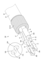
- FIG. 1 is a perspective view of a terminal module according to a first embodiment.
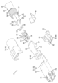
- FIG. 2 is an exploded perspective view of the terminal module according to the first embodiment.
- FIG. 3 is a side cross-sectional view of the terminal module according to the first embodiment.
- FIG. 4 is a cross-sectional view of the terminal module according to the first embodiment.
- FIG. 5 is a perspective view showing a state in which each spacer member individually covers an end region of each insulated electric wire in the terminal module of embodiment 1 to maintain the distance between the insulation barrel portion of each terminal and the impedance adjustment member.
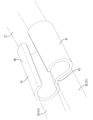
- FIG. 6 is a perspective view of an impedance adjusting member in the terminal module according to the first embodiment.
- FIG. 7 is a cross-sectional view of the terminal module according to the second embodiment.
- FIG. 1 is a perspective view of a terminal module according to a first embodiment.
- FIG. 2 is an exploded perspective view of the terminal module according to the first embodiment.
- FIG. 3 is a side cross-sectional view
- FIG. 8 is a perspective view showing a state in which the spacer member collectively covers each of the end regions of each insulated electric wire in the terminal module of the second embodiment, thereby maintaining the distance between the insulation barrel portion of each terminal and the impedance adjustment member.
- FIG. 9 is a side cross-sectional view of a terminal module according to the third embodiment.
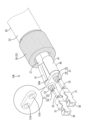
- Figure 10 is an oblique view showing a terminal module of embodiment 3, in which each spacer member having a fixing portion individually covers each end region of each insulated electric wire to maintain the distance between the insulation barrel portion of each terminal and the impedance adjustment member.
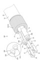
- FIG. 11 is an oblique view showing a terminal module of embodiment 4 in which a spacer member having two fixing portions collectively covers each end region of each insulated electric wire to maintain the distance between the insulation barrel portion of each terminal and the impedance adjustment member.
- FIG. 12 is a perspective view showing a state in which, in the terminal module of embodiment 5, each spacer member individually covers each end region of each insulated electric wire to maintain the distance between the wire barrel portion of each terminal and the impedance adjustment member.
- FIG. 13 is a perspective view showing a state in which the spacer member collectively covers each of the end regions of each insulated electric wire in the terminal module of embodiment 6, thereby maintaining the distance between the wire barrel portion of each terminal and the impedance adjustment member.
- the terminal module of the present disclosure comprises: (1) A shielded electric wire having an end portion exposed from a shield portion, a terminal connected to the end portion of the shielded electric wire, a conductive impedance adjustment member covering the end region of the shielded electric wire, and an insulating spacer member that maintains a gap between the terminal and the impedance adjustment member.
- the above configuration (1) can prevent contact (short circuit) between the terminal and the impedance adjustment member by the insulating spacer member, and can maintain a constant distance between the terminal and the impedance adjustment member, thereby suppressing impedance variations.
- the spacer member is preferably a tubular member that covers an end region of the insulated wire between the terminal and the impedance adjustment member.
- the above-mentioned configuration (2) can effectively suppress signal reflection at the end of the insulated electric wire by using the cylindrical spacer member.
- the spacer member is arranged in a state in which positional deviation in the longitudinal direction of the insulated electric wire is restricted by the terminal and the impedance adjustment member.
- a spacer member can be sandwiched between the terminal and the impedance adjustment member to hold them.
- the terminal module further includes an insulating terminal accommodating member that accommodates the terminals, and that the terminal accommodating member has a spacer accommodating portion that accommodates the spacer member while restricting the movement of the spacer member.
- the above-mentioned configuration (4) can restrict rattling of the spacer member accommodated in the spacer accommodating portion of the terminal accommodating member, and therefore can more effectively suppress variations in impedance.
- the spacer member is arranged to individually cover each of the end regions of the insulated electric wires extending from the two terminals.
- the spacer member is integrally formed so as to collectively cover each of the end regions of the insulated electric wires extending from the two terminals.
- the above configuration (6) can maintain a constant distance between the ends of the insulated wires extending from the two terminals by using the spacer member, thereby preventing the occurrence of crosstalk, etc., and improving impedance matching.
- the terminal has a barrel portion that holds an end of the insulated electric wire, and the spacer member has a fixing portion that is clamped and fixed radially of the insulated electric wire between the end of the insulated electric wire and the barrel portion.
- the above-mentioned configuration (7) can maintain constant relative positions of the spacer member with respect to each of the insulated electric wire and the terminal, and therefore can more effectively suppress variations in impedance.
- the insulated electric wire has a core wire and an insulating coating surrounding an outer periphery of the core wire, and the fixing portion is tubular and covers the core wire protruding from the insulating coating at the end of the insulated electric wire.
- the barrel portion can hold the core wire via the fixing portion, and the fixing portion can perform the function of insulating the insulated electric wire.
- the first embodiment of the present disclosure illustrates a terminal module 10 for communication in a vehicle such as an electric vehicle or a hybrid vehicle.
- the terminal module 10 according to the first embodiment includes a shielded electric wire 20, a terminal 30, an impedance adjusting member 40, a spacer member 50, a terminal housing member 60, and an outer conductor 70.
- the terminal module 10 is accommodated in a housing (not shown).
- the front end side of the shielded electric wire 20 in the longitudinal direction is defined as the front.
- the up-down direction is based on the up-down direction in each of Figs. 1 to 6. These directions do not necessarily coincide with the reference directions when the terminal module 10 is mounted on a vehicle (not shown).
- the shielded electric wire 20 has two covered electric wires 21, a shield portion 22 collectively surrounding the outer periphery of each covered electric wire 21, and a sheath 23 surrounding the outer periphery of the shield portion 22.
- the shield portion 22 is, for example, a braided wire in which a plurality of metal wires are braided into a cylindrical shape.
- the shield portion 22 may be a metal foil such as a copper foil.
- the two coated electric wires 21 are, for example, twisted pair wires.
- Each coated electric wire 21 has a core wire 24, which is a conductor, and an insulating coating 25 that surrounds the outer periphery of the core wire 24.
- the core wire 24 is made of a metal material such as copper, copper alloy, aluminum, or aluminum alloy.
- the core wire 24 may be a single metal wire, or may be a twisted wire in which multiple metal wires are twisted together.
- the sheath 23 and the insulating coating 25 are made of synthetic resin and have insulating properties and flexibility.
- the end (front end, terminal portion) of the shielded electric wire 20 is subjected to terminal processing such as stripping.
- the sheath 23 is removed from the end of the shielded electric wire 20 by terminal processing, exposing each end of the coated electric wire 21 and the braided wire.
- the part of the shield portion 22 that extends from the front end of the sheath 23 and is exposed is folded back to form an inverted portion 26 that covers the outer periphery of the sheath 23.
- the end of each coated electric wire 21 forms an exposed portion 27 that is exposed forward from the inverted portion 26 of the shield portion 22.
- the end of the exposed portion 27 has the insulating coating 25 removed by terminal processing such as stripping, exposing the core wire 24.
- the exposed portion 27 is covered with an impedance adjustment member 40 and constitutes the end region of the coated electric wire 21.
- the end region of the coated electric wire 21 is also covered with a spacer member 50.
- the end region of the coated electric wire 21 is constituted by the insulating coating 25 of the exposed portion 27.
- the terminal 30 is an inner conductor disposed inside the outer conductor 70.
- the terminal 30 is integrally formed by bending a conductive metal plate material or the like. As shown in Fig. 2, the terminal 30 is provided so as to be connectable to each of the two covered electric wires 21, and two terminals 30 are provided in one terminal module 10.
- the terminal 30 has a mating connection portion 31 at the front portion thereof that is connected to a mating terminal (mating inner conductor) not shown, and barrel portions 32, 33 at the rear portion thereof that are connected to the exposed portion 27 of the covered electric wire 21.
- the mating connection part 31 has a pair of upper and lower elastically deformable connection pieces 34 inside.
- Each connection piece 34 is elastically deformable and is connected to a tab of a mating terminal (not shown) inserted inside the mating connection part 31.
- the barrel portion has a wire barrel portion 32 and an insulation barrel portion 33 arranged side by side with the wire barrel portion 32 behind the wire barrel portion 32. Both the wire barrel portion 32 and the insulation barrel portion 33 are open barrel shaped.
- the wire barrel portion 32 is crimped so as to wrap around the core wire 24 exposed at the end of the exposed portion 27, and is electrically and mechanically connected to the core wire 24.
- the insulation barrel portion 33 is crimped so as to wrap around the insulating coating 25 at the end of the exposed portion 27, and is mechanically connected to the insulating coating 25.
- the impedance adjustment member 40 is integrally formed by bending a conductive metal plate, etc. As shown in Fig. 6, the impedance adjustment member 40 has a pair of left and right adjustment body parts 41 that cover the insulating coating 25 of the exposed part 27, which is the end region of each coated electric wire 21, and a connecting part 42 that connects the adjustment body parts 41 together.
- Each adjustment body portion 41 has a cylindrical shape with a C-shaped cross section, and is bent from the open state shown in Fig. 2 so as to fit along the outer circumferential surface of the insulating coating 25.
- the outer periphery of the insulating coating 25 is covered by the adjustment body portion 41.
- the connecting portion 42 is disposed between each adjustment body portion 41, and has an upwardly curved shape.
- the spacer member 50 is made of synthetic resin and has insulating properties. In the case of the present embodiment 1, as shown in FIG. 5, two spacer members 50 are provided so as to correspond to each of the two coated electric wires 21 individually.
- the spacer member 50 is tubular or annular and covers the end region of the coated electric wire 21 between the terminal 30 and the impedance adjustment member 40, and is, for example, cylindrical or annular.
- the spacer member 50 has an electric wire insertion hole 51.
- the electric wire insertion hole 51 has an inner diameter corresponding to the outer diameter of the insulating coating 25 of the exposed portion 27.
- the spacer member 50 is fitted into the insulating coating 25 of the exposed portion 27.
- the spacer member 50 has an electric wire insertion hole 51 with an inner diameter smaller than the outer diameter of the insulating coating 25, and is fitted into the insulating coating 25 in a state in which the insulating coating 25 is compressed in the radial direction (see FIG. 3).
- the spacer member 50 has an outer diameter equal to or smaller than the outer diameter of the adjustment body 41, and is accommodated in a state where its movement is restricted relative to a spacer accommodating portion 69 of the terminal accommodating member 60 (see FIG. 4).
- the front and rear surfaces of the spacer member 50 are both formed along the radial direction of the spacer member 50. As shown in FIG. 3, when the spacer member 50 is accommodated in the spacer accommodating portion 69, the front surface of the spacer member 50 is arranged so as to be in contact with the rear end surface of the terminal 30, which is the rear end surface of the insulation barrel portion 33 in the case of this embodiment 1.
- the rear surface of the spacer member 50 is arranged so as to be in contact with the front end surface of the impedance adjustment member 40.
- the length (thickness) of the spacer member 50 in the front-rear direction is sufficiently small, and is equal to the interval that is naturally formed between the impedance adjustment member 40 and the terminal 30 when the impedance adjustment member 40 is arranged close to the terminal 30 within the allowable range, for example.
- the spacer member 50 maintains the distance between the terminal 30 and the impedance adjustment member 40, and has the function of keeping the terminal 30 and the impedance adjustment member 40 in an insulated state.
- the terminal accommodating member 60 is a dielectric material made of synthetic resin and has insulating properties. As shown in Fig. 2, the terminal accommodating member 60 has a lower member 61 and an upper member 62 that is attached to the lower member 61 from above.
- the lower member 61 has a flat plate-shaped lower main body portion 63 and a pair of frame-shaped lower locking portions 64 that rise from both left and right ends of the lower main body portion 63.
- the upper member 62 has a flat plate-shaped upper main body portion 65 and a pair of rib-shaped upper locking portions 66 (only one is shown in Fig. 2) that protrude from both left and right ends of the upper main body portion 65.
- the upper member 62 has a pair of side portions 67 that protrude downward from both the left and right ends of the upper main body portion 65, and a partition portion 68 that protrudes downward from the left and right center of the upper main body portion 65.
- Each side portion 67 and partition portion 68 is plate-shaped with the plate surface facing in the left and right direction.
- the rear portion of the upper member 62 has a pair of spacer accommodating portions 69 on both the left and right sides of the partition portion 68.
- Each spacer member 50 is inserted into and accommodated in each spacer accommodating portion 69 while being fitted into the insulating coating 25 of the exposed portion 27.
- Each spacer accommodating portion 69 is partitioned by the lower member 61 and the upper member 62 when the spacer member 50 is accommodated therein. As shown in FIG. 4, the spacer member 50 is sandwiched between the partition portion 68 and the side portion 67 to restrict left-right movement, and is sandwiched between the upper main body portion 65 and the lower main body portion 63 to restrict up-down movement. In other words, the spacer member 50 is restricted from up-down and left-right movement when accommodated in the spacer accommodating portion 69.
- the outer conductor 70 is formed by bending a conductive metal plate. As shown in Figs. 1 and 2, the outer conductor 70 has a main body member 71 and a cover member 72.
- the main body member 71 has a square tube-shaped tube portion 73 that covers the outer periphery of the terminal accommodating member 60 (the lower member 61 and the upper member 62 in a combined state), and an extension portion 74 that extends rearward from the tube portion 73.
- the tube portion 73 has a plurality of elastic contact portions 75 that can be connected to a mating outer conductor (not shown). As shown in Fig. 3, the extension portion 74 contacts the lower surface of the inverted portion 26 of the shield portion 22. As shown in Fig.
- the cover member 72 is placed on the rear portion of the main body member 71 from above.
- the cover member 72 is also bent to cover the outer periphery of the inverted portion 26 and is closely attached to the outer surface of the extension portion 74 (see Fig. 3).
- the outer conductor 70 can form a part of the ground circuit by electrically and mechanically connecting the extension 74 and the cover member 72 to the shield portion 22.
- the terminals 30 and the outer conductor 70 are kept insulated from each other by the terminal accommodating member 60.
- Terminal module function An example of a manufacturing method of the terminal module 10 will be described below.
- the exposed portion 27 of each insulated electric wire 21 is inserted into the electric wire insertion hole 51 of each spacer member 50.
- the wire barrel portion 32 of each terminal 30 is crimped to the core wire 24 of the exposed portion 27 of each insulated electric wire 21, and the insulation barrel portion 33 of each terminal 30 is crimped to the insulating coating 25 of the exposed portion 27 of each insulated electric wire 21.
- the front surface of each spacer member 50 is abutted against the rear end surface of the insulation barrel portion 33 of each terminal 30.
- the front end of each adjustment body portion 41 of the impedance adjustment member 40 in the open state is abutted against the rear surface of the spacer member 50, and in this state, each adjustment body portion 41 is bent.
- each adjustment body 41 is crimped to the insulating coating 25 of the exposed portion 27 of each insulated electric wire 21, and the front end of each adjustment body 41 can contact the rear surface of each spacer member 50.
- Each spacer member 50 is sandwiched in the front-rear direction between the insulation barrel portion 33 of each terminal 30 and each adjustment body 41 of the impedance adjustment member 40, so that it is positioned in a state where its positional deviation in the front-rear direction is restricted relative to the insulating coating 25 of the exposed portion 27 of each insulated electric wire 21 (see FIG. 3).
- a predetermined distance (a predetermined distance that is constant between products) corresponding to the front-rear length (thickness) of each spacer member 50 is maintained between the insulation barrel portion 33 of each terminal 30 and each adjustment body 41 of the impedance adjustment member 40.
- the terminals 30 are accommodated in the spaces on both the left and right sides of the partition 68 in the upper member 62, and the spacer members 50 are accommodated in the spacer accommodating sections 69, and the upper member 62 and the lower section are held in a combined state.
- the spacer members 50 By accommodating the spacer members 50 in the spacer accommodating sections 69, the movement of the spacer members 50 is restricted as described above (see FIG. 4).
- the terminal module 10 includes an insulating spacer member 50 that maintains the distance between the terminal 30 and the impedance adjustment member 40.
- the spacer member 50 prevents contact (short circuit) between the terminal 30 and the impedance adjustment member 40 and maintains a constant distance between the terminal 30 and the impedance adjustment member 40, thereby suppressing impedance variations.
- the spacer member 50 is a cylindrical member that covers the end region (exposed portion 27) of the coated electric wire 21, and therefore can effectively suppress signal reflection in the end region of the coated electric wire 21.
- the spacer member 50 is sandwiched between the terminal 30 and the impedance adjustment member 40, and is held in a state where positional deviation in the front-rear direction, which is the length direction of the coated electric wire 21, is restricted. Furthermore, the spacer member 50 is accommodated in the spacer accommodating portion 69 of the terminal accommodating member 60 in a state where its own movement is restricted. Therefore, in addition to being able to determine the position of the spacer member 50 relative to each of the terminal 30 and the impedance adjustment member 40, it is also possible to restrict rattling of the spacer member 50 relative to the terminal accommodating member 60. Therefore, the configuration of this embodiment 1 can stably maintain the distance between the terminal 30 and the impedance adjustment member 40 via the spacer member 50, and can more effectively suppress impedance variations.
- the spacer member 50 is provided so as to individually cover each of the coated electric wires 21 extending from the two terminals 30. Therefore, for example, when one of the two coated electric wires 21 is changed, it is only necessary to replace the spacer member 50 corresponding to one coated electric wire 21, and there is no need to replace the spacer member 50 corresponding to the other coated electric wire 21.
- a terminal module 10A according to the second embodiment of the present disclosure has a spacer member 50A and a spacer accommodating portion 69A that accommodates the spacer member 50A, which are different from those of the first embodiment.
- the rest of the terminal module 10A is the same as that of the first embodiment.
- structures that are the same as or equivalent to those of the first embodiment are given the same reference numerals, and duplicate descriptions will be omitted.
- the spacer member 50A is an integrated type that collectively covers each of the end regions (exposed portions 27) of each coated electric wire 21.
- the spacer member 50A is plate-shaped and has a thickness in the front-to-rear direction.
- the spacer member 50A has a track-shaped cross section, linear upper and lower surfaces that extend along the left-to-right direction, and left and right side surfaces that curve and extend in the up-down direction.
- the thickness of the spacer member 50A in the front-to-rear direction is the same as that of the spacer member 50A in embodiment 1, and is large enough to maintain a predetermined distance between the terminal 30 and the impedance adjustment member 40.
- the front and rear surfaces of the spacer member 50A are both formed along the radial direction of the spacer member 50A.
- the front surface of the spacer member 50A is positioned so that it can come into contact with the rear end surface of the insulation barrel portion 33 of the terminal 30.
- the rear surface of the spacer member 50A is positioned so that it can come into contact with the front end surface of the impedance adjustment member 40.
- the spacer member 50A has a number of wire insertion holes 51A (two in the case of the second embodiment) corresponding to the number of each coated electric wire 21.
- the wire insertion holes 51A are arranged side by side at intervals in the left-right direction in the spacer member 50A.
- the inner diameter of each wire insertion hole 51A is the same as the inner diameter of the spacer member 50A in the first embodiment.
- the rear of the terminal accommodating member 60 has one spacer accommodating section 69A that does not have a portion corresponding to the partition section 68 of the first embodiment.
- the spacer member 50A is accommodated in the spacer accommodating section 69A, and is sandwiched between the left and right side sections 67 to restrict left-right movement, and is sandwiched between the upper main body section 65 and the lower main body section 63 to restrict up-down movement.
- the spacer member 50A is restricted from up-down and left-right movement while accommodated in the spacer accommodating section 69A.
- the insulating spacer member 50A maintains the distance between each terminal 30 and the impedance adjustment member 40, thereby suppressing impedance variation.
- the spacer member 50A maintains a constant distance between each exposed portion 27 adjacent in the left-right direction, thereby preventing crosstalk between each exposed portion 27 adjacent in the left-right direction, and improving impedance consistency.
- a terminal module 10B according to the third embodiment of the present disclosure has a spacer member 50B different from that of the first embodiment. Also, in the end region (exposed portion 27) of each coated electric wire 21, the core wire 24 protrudes from the insulating coating 25 by a longer amount than in the first embodiment. The rest is the same as the first embodiment.
- structures that are the same as or equivalent to those in the first embodiment are given the same reference numerals, and duplicate descriptions will be omitted.
- the spacer member 50B has a top hat shape (convex shape) in side view, and has a spacer main body 52B and a fixing portion 53B that protrudes forward from the spacer main body 52B.
- the spacer main body 52B is tubular or annular, for example, cylindrical or annular.
- the fixing portion 53B is also tubular or annular, for example, cylindrical or annular.
- the fixing portion 53B is one size smaller than the spacer main body 52B in front view, and has an outer circumferential surface that is concentric with the spacer main body 52B.
- the front and rear surfaces of the spacer body 52B are both formed along the radial direction of the spacer member 50B.
- the front surface of the spacer body 52B is connected at a right angle to the outer peripheral surface of the fixing portion 53B.
- the outer peripheral surface of the fixing portion 53B is formed along the front-to-rear direction.
- the front surface of the spacer body 52B is arranged so that it can come into contact with the rear end surface of the insulation barrel portion 33 of the terminal 30.
- the rear surface of the spacer body 52B is arranged so that it can come into contact with the front end surface of the impedance adjustment member 40.
- the outer peripheral surface of the fixing portion 53B is arranged so that it can come into contact with the insulation barrel portion 33 of the terminal 30 in a tight contact state.
- the spacer member 50B has an electric wire insertion hole 51B inside that penetrates in the front-rear direction from the spacer body portion 52B to the fixing portion 53B.
- the electric wire insertion hole 51B has an inner diameter that corresponds to the outer diameter of the core wire 24 exposed at the end of the exposed portion 27.
- the spacer member 50B is provided so as to cover the end region (exposed portion 27) of each coated electric wire 21 individually, as in the first embodiment.
- the core wire 24 exposed at the end of the exposed portion 27 is inserted into the electric wire insertion hole 51B of the spacer member 50B.
- the fixing portion 53B of the spacer member 50B is crimped by the insulation barrel portion 33, and is fixed (held) in a radially compressed state between the insulation barrel portion 33 and the core wire 24.
- the rear surface of the spacer main body portion 52B is arranged so as to be able to come into contact with the front end surface of the impedance adjustment member 40, and is arranged so as to be able to come into contact with the front end surface of the insulating coating 25 (see FIG. 9).
- the insulating spacer member 50B maintains the distance between the terminal 30 and the impedance adjustment member 40, so that the impedance variation can be suppressed.
- the spacer member 50B has a fixing portion 53B that is sandwiched and fixed between the end region (exposed portion 27) of the coated electric wire 21 and the insulation barrel portion 33 in the radial direction of the coated electric wire 21. Therefore, the configuration of the third embodiment can maintain a constant relative position of the spacer member 50B with respect to each of the coated electric wire 21 and the terminal 30, and can more effectively suppress the impedance variation.
- the fixing portion 53B has a cylindrical shape that covers the core wire 24 protruding from the insulating coating 25 at the end of the coated electric wire 21, and can function as the insulating coating 25 of the coated electric wire 21.
- the diameter dimension of the insulation barrel portion 33 in the crimped state (closed state) can be suppressed.
- a terminal module 10C includes an integrated spacer member 50C that collectively covers the end regions (exposed portions 27) of the coated electric wires 21.
- the spacer member 50C has a plate-shaped spacer body portion 52C that has a thickness in the front-rear direction.
- the spacer body portion 52C has a track-shaped cross section and has the same outer shape as the spacer member 50A of the second embodiment.
- the spacer member 50C has two fixing portions 53C that protrude forward from the spacer body portion 52C.
- the fixing portions 53C protrude from the spacer body portion 52C in a line spaced apart relationship in the left-right direction.
- Each fixing portion 53C has the same shape as the fixing portion 53B in the third embodiment.
- the spacer member 50C has two wire insertion holes 51C inside, which penetrate in the front-rear direction from the spacer body 52C to each fixing portion 53C.
- each wire insertion hole 51C has an inner diameter corresponding to the outer diameter of the core wire 24 exposed at the end of the exposed portion 27.
- each coated electric wire 21 is inserted into each electric wire insertion hole 51C.
- the front end face of the insulating coating 25 at the end of each coated electric wire 21 is arranged so as to be in contact with the rear surface of the spacer body portion 52C.
- the front end face of the impedance adjustment member 40 is also arranged so as to be in contact with the rear surface of the spacer body portion 52C.
- Each fixing portion 53C is crimped by the insulation barrel portion 33 of each terminal 30, and is fixed (held) in a radially compressed state between the insulation barrel portion 33 and the core wire 24.
- the insulating spacer member 50C maintains the distance between the terminal 30 and the impedance adjustment member 40, so that the impedance variation can be suppressed.
- the spacer member 50C maintains the distance between the exposed portions 27 adjacent in the left-right direction constant, so that the occurrence of crosstalk between the exposed portions 27 adjacent in the left-right direction can be prevented, and the impedance consistency can be improved.
- the relative position of the spacer member 50C with respect to each of the coated electric wire 21 and the terminal 30 can be maintained constant by each fixing portion 53C, so that the impedance variation can be suppressed more effectively.
- each fixing portion 53C is cylindrical and covers the core wire 24 protruding from the insulating coating 25 at the end of the coated electric wire 21, so that it can function as the insulating coating 25 of the coated electric wire 21.
- a terminal module 10D includes a spacer member 50D that individually covers each end region (exposed portion 27) of each coated electric wire 21, and a terminal 30D that does not have a portion corresponding to the insulation barrel portion 33 of embodiment 1 above.
- terminal 30D is composed only of wire barrel portion 32.
- Terminal 30D is shorter in the front-rear direction than terminal 30 of embodiment 1 above, since it does not have a portion equivalent to insulation barrel portion 33.
- the rear end surface of wire barrel portion 32 becomes the rear end surface of terminal 30D.
- the spacer member 50D is tubular or annular, for example, cylindrical or annular.
- the spacer member 50D has an outer shape similar to that of the spacer member 50 of the first embodiment.
- the spacer member 50D has a wire insertion hole 51D.
- the inner diameter of the wire insertion hole 51D corresponds to the outer diameter of the core wire 24 exposed at the end of the exposed portion 27.
- the core wire 24 exposed at the exposed portion 27 is inserted into the wire insertion hole 51D.
- the front surface of the spacer member 50D is arranged so that it can come into contact with the rear end surface of the wire barrel portion 32.
- the rear surface of the spacer member 50D is arranged so that it can come into contact with the front end surface of the impedance adjustment member 40.
- the rear surface of the spacer member 50D is arranged so that it can come into contact with the front end surface of the insulating coating 25 of the exposed portion 27.
- an insulating spacer member 50D is sandwiched and held between the wire barrel portion 32 of the terminal 30D and the impedance adjustment member 40 in a state in which movement is restricted.
- the distance between the terminal 30D and the impedance adjustment member 40 is maintained, so that impedance variations can be suppressed.
- the barrel portion of the terminal 30D is composed only of the wire barrel portion 32, so that the terminal module 10D can be shortened in the front-rear direction.
- a terminal module 10E includes an integrated spacer member 50E that collectively covers each of the end regions (exposed portions 27) of each coated electric wire 21, and a terminal 30E that does not have a portion corresponding to the insulation barrel portion 33 of embodiment 1 above.
- the barrel portion of terminal 30E is composed only of wire barrel portion 32.
- the rear end surface of wire barrel portion 32 becomes the rear end surface of terminal 30E.
- the spacer member 50E is plate-shaped and has a thickness in the front-rear direction.
- the spacer member 50E has a track-shaped cross section and has the same outer shape as the spacer member 50A of the second embodiment.
- the spacer member 50E has two wire insertion holes 51E.
- the wire insertion holes 51E are arranged side by side and spaced apart in the left-right direction in the spacer member 50E.
- the inner diameter of each wire insertion hole 51E corresponds to the outer diameter of the core wire 24 exposed at the end of each exposed portion 27.
- the core wire 24 exposed at the end of each exposed portion 27 is inserted into each wire insertion hole 51E.
- the spacer member 50E is sandwiched and held between the wire barrel portion 32 of each terminal 30E and the impedance adjustment member 40 in a state where movement is restricted.
- the insulating spacer member 50E maintains the distance between each terminal 30E and the impedance adjustment member 40, so that the impedance variation can be suppressed.
- the terminal module 10E can be shortened in the front-rear direction.
- the spacer member 50E maintains a constant distance between the exposed portions 27 adjacent in the left-right direction, the occurrence of crosstalk between the exposed portions 27 adjacent in the left-right direction can be prevented, and impedance consistency can be improved.
- the spacer member has a shape that covers the entire outer periphery of the end region of the insulated electric wire.
- the spacer member may have a portion that does not cover the outer periphery of the end region of the insulated electric wire, and may be formed, for example, in a C-shaped cross section.
- the spacer member has a cylindrical fixing portion that covers the outer periphery of the core wire exposed at the end of the insulated electric wire.
- the spacer member may have a cylindrical fixing portion that covers the outer periphery of the insulating coating at the end of the insulated electric wire.
- two terminals and two insulated electric wires are accommodated in one terminal accommodating member, whereas in other embodiments, one or three or more terminals and one or three or more insulated electric wires may be accommodated in one terminal accommodating member.
Landscapes
- Details Of Connecting Devices For Male And Female Coupling (AREA)
- Coupling Device And Connection With Printed Circuit (AREA)
Abstract
Un module de borne (10, 10A, 10B, 10C, 10D, 10E) comprend : un fil de blindage (20) ayant une partie de blindage (22) à partir de laquelle est exposée l'extrémité d'un fil guipé (21) ; une borne (30, 30D, 30E) connectée à l'extrémité du fil guipé (21) ; un élément de réglage d'impédance conducteur (40) qui recouvre la région d'extrémité du fil guipé (21) ; et un élément d'espacement isolant (50, 50A, 50B, 50C, 50D, 50E) qui maintient un intervalle entre la borne (30, 30D, 30E) et l'élément de réglage d'impédance (40).
Priority Applications (1)
| Application Number | Priority Date | Filing Date | Title |
|---|---|---|---|
| CN202480036788.3A CN121285911A (zh) | 2023-06-07 | 2024-05-29 | 端子模块 |
Applications Claiming Priority (2)
| Application Number | Priority Date | Filing Date | Title |
|---|---|---|---|
| JP2023-093735 | 2023-06-07 | ||
| JP2023093735A JP2024175759A (ja) | 2023-06-07 | 2023-06-07 | 端子モジュール |
Publications (1)
| Publication Number | Publication Date |
|---|---|
| WO2024253005A1 true WO2024253005A1 (fr) | 2024-12-12 |
Family
ID=93795924
Family Applications (1)
| Application Number | Title | Priority Date | Filing Date |
|---|---|---|---|
| PCT/JP2024/019766 Ceased WO2024253005A1 (fr) | 2023-06-07 | 2024-05-29 | Module de borne |
Country Status (3)
| Country | Link |
|---|---|
| JP (1) | JP2024175759A (fr) |
| CN (1) | CN121285911A (fr) |
| WO (1) | WO2024253005A1 (fr) |
Citations (6)
| Publication number | Priority date | Publication date | Assignee | Title |
|---|---|---|---|---|
| JP2004071404A (ja) * | 2002-08-07 | 2004-03-04 | Auto Network Gijutsu Kenkyusho:Kk | ツイストペア電線の端末部分のインピーダンス調整方法及びその端末処理構造 |
| JP2011009111A (ja) * | 2009-06-26 | 2011-01-13 | Yazaki Corp | 同軸ケーブル用コネクタ |
| JP2014038708A (ja) * | 2012-08-10 | 2014-02-27 | Auto Network Gijutsu Kenkyusho:Kk | 通信用ハーネス |
| JP2018112514A (ja) * | 2017-01-13 | 2018-07-19 | 日本特殊陶業株式会社 | 温度センサ |
| JP2020107563A (ja) * | 2018-12-28 | 2020-07-09 | 株式会社オートネットワーク技術研究所 | コネクタ、及びコネクタ構造体 |
| JP2022000836A (ja) * | 2020-06-19 | 2022-01-04 | 矢崎総業株式会社 | ケーブルアッセンブリ |
-
2023
- 2023-06-07 JP JP2023093735A patent/JP2024175759A/ja active Pending
-
2024
- 2024-05-29 WO PCT/JP2024/019766 patent/WO2024253005A1/fr not_active Ceased
- 2024-05-29 CN CN202480036788.3A patent/CN121285911A/zh active Pending
Patent Citations (6)
| Publication number | Priority date | Publication date | Assignee | Title |
|---|---|---|---|---|
| JP2004071404A (ja) * | 2002-08-07 | 2004-03-04 | Auto Network Gijutsu Kenkyusho:Kk | ツイストペア電線の端末部分のインピーダンス調整方法及びその端末処理構造 |
| JP2011009111A (ja) * | 2009-06-26 | 2011-01-13 | Yazaki Corp | 同軸ケーブル用コネクタ |
| JP2014038708A (ja) * | 2012-08-10 | 2014-02-27 | Auto Network Gijutsu Kenkyusho:Kk | 通信用ハーネス |
| JP2018112514A (ja) * | 2017-01-13 | 2018-07-19 | 日本特殊陶業株式会社 | 温度センサ |
| JP2020107563A (ja) * | 2018-12-28 | 2020-07-09 | 株式会社オートネットワーク技術研究所 | コネクタ、及びコネクタ構造体 |
| JP2022000836A (ja) * | 2020-06-19 | 2022-01-04 | 矢崎総業株式会社 | ケーブルアッセンブリ |
Also Published As
| Publication number | Publication date |
|---|---|
| JP2024175759A (ja) | 2024-12-19 |
| CN121285911A (zh) | 2026-01-06 |
Similar Documents
| Publication | Publication Date | Title |
|---|---|---|
| JP7032978B2 (ja) | L形同軸端子を備えたコネクタおよびその製造方法 | |
| US10355463B2 (en) | Shield conductive path | |
| US7530848B2 (en) | Shielded connector | |
| CN108475889A (zh) | 大功率电连接器 | |
| US12191598B2 (en) | Connector, wiring harness and assembly method therefor | |
| WO2020137963A1 (fr) | Câble équipé d'une borne, module de borne et connecteur | |
| JP5419512B2 (ja) | スリーブを用いた同軸ケーブルとシールド端子の接続構造 | |
| JP2022153116A (ja) | 電気コネクタ | |
| JP7619246B2 (ja) | シールド端子 | |
| US10700476B2 (en) | Electrical connector | |
| US20180261960A1 (en) | Shield connector and manufacturing method therefor | |
| WO2024253005A1 (fr) | Module de borne | |
| CN110504597B (zh) | 屏蔽连接器 | |
| JP6919642B2 (ja) | 電気コネクタ | |
| JP6813725B2 (ja) | コネクタ | |
| JP2018010720A (ja) | 電気コネクタ | |
| JP5058869B2 (ja) | 同軸コネクタ及び同軸コネクタの組み付け方法 | |
| JP2023023211A (ja) | コネクタの接続構造 | |
| JP7644076B2 (ja) | コネクタ | |
| JP7697867B2 (ja) | シールド構造 | |
| WO2025164371A1 (fr) | Structure de connexion d'un fil électrique blindé et connecteur | |
| JP2025002954A (ja) | 端子ユニット | |
| JP2024092558A (ja) | シールドコネクタ | |
| JP2025041200A (ja) | コネクタ | |
| CN117546376A (zh) | 触头、连接器以及线缆组装体 |
Legal Events
| Date | Code | Title | Description |
|---|---|---|---|
| 121 | Ep: the epo has been informed by wipo that ep was designated in this application |
Ref document number: 24819236 Country of ref document: EP Kind code of ref document: A1 |
|
| WWE | Wipo information: entry into national phase |
Ref document number: CN2024800367883 Country of ref document: CN |
|
| NENP | Non-entry into the national phase |
Ref country code: DE |