WO2024253042A1 - 微小粒子分取装置及び微小粒子分取方法 - Google Patents
微小粒子分取装置及び微小粒子分取方法 Download PDFInfo
- Publication number
- WO2024253042A1 WO2024253042A1 PCT/JP2024/020070 JP2024020070W WO2024253042A1 WO 2024253042 A1 WO2024253042 A1 WO 2024253042A1 JP 2024020070 W JP2024020070 W JP 2024020070W WO 2024253042 A1 WO2024253042 A1 WO 2024253042A1
- Authority
- WO
- WIPO (PCT)
- Prior art keywords
- sample liquid
- sheath
- sorting device
- liquid
- vibration
- Prior art date
- Legal status (The legal status is an assumption and is not a legal conclusion. Google has not performed a legal analysis and makes no representation as to the accuracy of the status listed.)
- Ceased
Links
Images




Classifications
-
- G—PHYSICS
- G01—MEASURING; TESTING
- G01N—INVESTIGATING OR ANALYSING MATERIALS BY DETERMINING THEIR CHEMICAL OR PHYSICAL PROPERTIES
- G01N15/00—Investigating characteristics of particles; Investigating permeability, pore-volume or surface-area of porous materials
- G01N15/10—Investigating individual particles
- G01N15/14—Optical investigation techniques, e.g. flow cytometry
- G01N15/1404—Handling flow, e.g. hydrodynamic focusing
- G01N15/1409—Handling samples, e.g. injecting samples
-
- G—PHYSICS
- G01—MEASURING; TESTING
- G01N—INVESTIGATING OR ANALYSING MATERIALS BY DETERMINING THEIR CHEMICAL OR PHYSICAL PROPERTIES
- G01N15/00—Investigating characteristics of particles; Investigating permeability, pore-volume or surface-area of porous materials
- G01N15/10—Investigating individual particles
- G01N15/14—Optical investigation techniques, e.g. flow cytometry
- G01N15/1429—Signal processing
Definitions
- This disclosure relates to a microparticle sorting device and a microparticle sorting method.
- Microparticle sorting devices that analyze microparticles contained in liquids are used to measure microparticles such as cells. These microparticle sorting devices generate droplets containing microparticles and sort the droplets according to the microparticles contained therein.
- the droplets generated by the microparticle sorting device are composed of sheath liquid that contains sample liquid that contains microparticles such as cells.
- a nozzle that ejects droplets is disposed in the microparticle sorting device.
- the sample liquid and sheath liquid are introduced into the nozzle. At this time, the sample liquid flows in a direction toward the droplet ejection port using a tubular introduction tube.
- vibrations are applied to the sheath liquid by a vibration unit. This vibration causes droplets to be formed at the nozzle ejection port.
- the introduction tube for the sample liquid and the vibration part of the vibration unit are arranged coaxially, which creates problems such as a complicated water-stopping structure for the nozzle, reducing convenience.
- This disclosure therefore proposes a microparticle sorting device and a microparticle sorting method that offer improved convenience.
- the microparticle sorting device includes a droplet generating unit that ejects droplets containing a sample liquid containing microparticles and a sheath liquid from an ejection port, a sheath liquid introducing unit that introduces the sheath liquid into the droplet generating unit, a sample liquid introducing unit that is configured as a tube inserted into the droplet generating unit and introduces the sample liquid in a direction toward the ejection port, and a vibration unit that has a vibration unit in contact with the sheath liquid and applies vibration to the sheath liquid from a direction different from the introduction direction of the sample liquid.
- FIG. 1 is a diagram showing a configuration example of a microparticle sorting device according to an embodiment of the present disclosure.
- 1 is a diagram showing a configuration example of a microparticle sorting device according to a first embodiment of the present disclosure.
- 1 is a diagram showing a configuration example of a microparticle sorting device according to a first embodiment of the present disclosure.
- 1 is a diagram showing a configuration example of a microparticle sorting device according to a first embodiment of the present disclosure.
- FIG. 4 is a diagram showing an example of wave motion of a sheath liquid according to the first embodiment of the present disclosure.
- 1A to 1C are diagrams illustrating an example of a microparticle sorting method according to a first embodiment of the present disclosure.
- FIG. 1 is a diagram showing a configuration example of a microparticle sorting device according to an embodiment of the present disclosure.
- 1 is a diagram showing a configuration example of a microparticle sorting device according to a first embodiment of the present
- FIG. 13 is a diagram showing a configuration example of a microparticle sorting device according to a second embodiment of the present disclosure.
- FIG. 13 is a diagram showing a configuration example of a microparticle sorting device according to a second embodiment of the present disclosure.
- FIG. 13 illustrates an example of introducing sheath fluid according to an embodiment of the present disclosure.
- FIG. 13 is a diagram illustrating an example of bubble removal according to a second embodiment of the present disclosure.
- FIG. 13 is a diagram showing a configuration example of a microparticle sorting device according to a third embodiment of the present disclosure.
- FIG. 2 is a diagram illustrating a configuration example of a vibration unit according to an embodiment of the present disclosure.
- FIG. 1 is a diagram showing a configuration example of a microparticle sorting device according to an embodiment of the present disclosure.
- the figure is a schematic diagram showing a configuration example of the microparticle sorting device 1.
- the microparticle sorting device 1 is a device that irradiates light onto particles aligned in a flow channel, detects light emitted from each particle, imparts a positive (+) or negative (-) charge to droplets containing the particles based on the detection signal, or makes them uncharged, splits the droplets into their respective droplet trajectories using a deflection plate, and collects the target particles.
- the microparticle sorting device 1 includes a droplet generating unit 100, a light source 181, a detection unit 182, an analysis unit 183, a deflection plate 190, and a collection container 193.
- the droplet generating unit 100 generates droplets containing a sample liquid (sample liquid 102) containing a specimen such as a cell, and a sheath liquid (sheath liquid 101) that encases the sample liquid.
- sample liquid 102 sample liquid
- sheath liquid 101 sheath liquid
- the figure shows a cross-sectional view illustrating an outline of the droplet generating unit 100.
- the droplet generating unit 100 includes a flow chamber 110, a flow cell 113, a nozzle 114, and a vibration unit 140.
- the droplet generating unit 100 in the figure further includes an exhaust unit 150 and an exhaust pipe 151, which will be described later in FIG. 11.
- the flow chamber 110 is a container into which the sample liquid and sheath liquid are introduced. This flow chamber 110 forms a flow path for the introduced sample liquid and sheath liquid.
- the flow chamber 110 is provided with a sample liquid introduction section holder 111 that holds a sample liquid introduction section 130 through which the sample liquid is introduced, and sheath liquid introduction sections 120 and 121 (not shown) that introduce the sheath liquid.
- the flow chamber 110 has an opening formed at its end that constitutes an outlet for the sample liquid and sheath liquid.
- the flow cell 113 is configured as a tube connected to the opening of the flow chamber 110 and forms a flow path for the sample liquid and the sheath liquid. This flow cell 113 provides an area for measuring microparticles contained in the sheath liquid flowing through it.
- the nozzle 114 is connected to the flow cell 113 so that the sample liquid and sheath liquid flow through it and are ejected from the ejection port 115.
- the sample liquid and sheath liquid ejected from the ejection port 115 form droplets.
- the droplets are charged.
- This charging can be achieved by an electrical signal supplied via electrodes connected to the flow chamber 110 or the like. Details of the charging will be described later with reference to FIG. 11.
- the vibration unit 140 applies vibrations to the fluid containing the sheath liquid.
- This vibration unit 140 applies vibrations to the fluid containing the sheath liquid by supplying a driving voltage. This allows the fluid to be continuously broken into droplets, generating a fluid stream (flow of droplets).
- the droplet generating unit 100 has a flow path through which a fluid containing at least a sheath liquid flows. If necessary, this flow path may also carry a sample liquid containing particles and a sheath liquid that flows so as to enclose the sample liquid.
- the flow chamber 110 is formed with a flow path 201 through which the sheath liquid flows and a flow path 202 through which the sample liquid flows.
- a flow path 203 is formed in the flow cell 113.
- the bottom of the flow chamber 110 narrows in a tapered shape, and the end is connected to the flow cell 113.
- a laminar flow is formed in which the sheath liquid surrounds the sample liquid. With this laminar flow maintained, the flow path transitions to the flow path 203 of the flow cell 113.
- the flow path 203 can be configured so that the particles flow in a roughly single file.
- detection is performed by irradiating light in the flow path 203 of the flow cell 113.
- a removable nozzle 114 is disposed at the end of the flow path 203.
- the inside of the nozzle 114 is configured in a slope shape that continuously narrows from the outlet of the flow cell 113 to the discharge port 115.
- the sample liquid and sheath liquid are vibrated by a vibration unit 140 disposed in the flow chamber 110.
- the liquid column 2 ejected from the discharge port 115 advances vertically downward while expanding the constriction formed at the same frequency as the vibration of the vibration unit 140, and changes into a droplet 3 at the break-off position from the discharge port 115.
- the light source 181 irradiates light onto the microparticles flowing through the flow cell 113.
- a light source that irradiates laser light can be used as the light source 181.
- the detection unit 182 detects light from particles contained in the sample liquid flowing through the flow cell 113. As described above, the flow cell 113 is irradiated with light from the light source 181. The particles contained in the sample liquid flowing through the flow cell 113 emit light corresponding to the light from the light source 181. The light from these particles is fluorescent light or scattered light, and the light corresponds to the properties of the particles. The detection unit 182 detects the light from these particles and outputs the detection result to the analysis unit 183.
- the detection unit 182 can be configured, for example, by an image sensor.
- the analysis unit 183 calculates the characteristic quantities of the particles contained in the sample liquid flowing through the flow cell 113 based on the detection results of the detection unit 182. This analysis unit 183 calculates the characteristic quantities such as the size, shape, and internal structure of the particles from the fluorescence and scattered light detected by the detection unit 182. The analysis unit 183 also generates an electrical signal that charges the droplets 3 based on the calculated characteristic quantities and the sorting conditions.
- the deflection plates 190 deflect the direction of travel of each droplet 3 in the aforementioned fluid stream by the electrical force acting between the droplet 3 and the charge applied thereto, and guide the droplet 3 to a specified collection container 193 or the like. As shown in the figure, two deflection plates 190 are arranged opposite each other with the fluid stream in between. In FIG. 1, the opposing direction of the deflection plates 190 is shown in the horizontal direction. There is no particular limitation on the deflection plates 190, and conventionally known electrodes or the like can be used. Different voltages, positive or negative, are applied to the deflection plates 190. When the charged droplets 3 pass through the electric field formed by this voltage, an electrical force (Coulomb force) is generated, and each droplet 3 is attracted toward one of the deflection plates 190.
- Coulomb force Coulomb force
- the collection containers 193 may be arranged in a line in the direction in which the deflection plates 190 face each other (horizontal direction in FIG. 1).
- the type of collection container 193 is not particularly limited, and examples include plastic tubes and glass tubes.
- the number of collection containers 193 is also not particularly limited, but FIG. 1 shows an example in which three collection containers are installed.
- the collection containers 193 may be installed in a replaceable manner in a container for collection containers (not shown). For example, they may be arranged on a Z-axis stage (not shown) configured to be movable in a direction perpendicular to the discharge direction of the droplets 3 from the droplet generating unit 100 (vertical direction in FIG. 1) and the direction in which the deflection plates 190 face each other (horizontal direction in FIG. 1).
- the "sample” contained in the sample liquid in this disclosure is particularly microparticles.
- the microparticles may be particles having a size that allows them to flow through the flow path of the sample liquid introduction section 130 or the flow cell 113.
- the microparticles may be appropriately selected by those skilled in the art.
- examples of microparticles include biological microparticles such as cells, cell clumps, microorganisms, and ribosomes, as well as synthetic microparticles such as gel particles, beads, latex particles, polymer particles, and industrial particles.
- Bioparticles may include chromosomes, ribosomes, mitochondria, organelles (cell organelles), and the like that constitute various cells.
- Cells may include animal cells (e.g., blood cells, etc.) and plant cells.
- the cells may be blood cells or tissue cells, in particular.
- the blood cells may be suspension cells, such as T cells and B cells.
- the tissue cells may be adherent cultured cells or adherent cells dissociated from tissues, for example.
- Cell aggregates may include spheroids and organoids, for example.
- Microorganisms may include bacteria such as E. coli, viruses such as tobacco mosaic virus, fungi such as yeast, and the like.
- the biological microparticles may also include biological macromolecules, such as nucleic acids, proteins, and complexes thereof. These biological macromolecules may be, for example, those extracted from cells, or those contained in blood samples or other liquid samples.
- the synthetic microparticles may be, for example, microparticles made of organic or inorganic polymeric materials or metals.
- Organic polymeric materials may include polystyrene, styrene-divinylbenzene, polymethyl methacrylate, and the like.
- Inorganic polymeric materials may include glass, silica, magnetic materials, and the like.
- Metals may include gold colloids and aluminum, and the like.
- the synthetic microparticles may be, for example, gel particles, beads, and the like, and in particular may be gel particles or beads to which one or a combination of two or more selected from oligonucleotides, peptides, proteins, and enzymes is bound.
- the shape of the microparticles may be spherical or nearly spherical, or may be non-spherical.
- the size and mass of the microparticles may be appropriately selected by those skilled in the art depending on the size of the flow path of the sample liquid introduction section 130 or the flow cell 113.
- the size of the flow path of the sample liquid introduction section 130 or the flow cell 113 may also be appropriately selected depending on the size and mass of the microparticles.
- a chemical or biological label such as a fluorescent dye or a fluorescent protein, may be attached to the microparticles as necessary. The label may make it easier to detect the microparticles.
- the label to be attached may be appropriately selected by those skilled in the art.
- the label may be bound to a molecule (e.g., an antibody, an aptamer, DNA, RNA, etc.) that specifically reacts with the microparticles.
- a molecule e.g., an antibody, an aptamer, DNA, RNA, etc.
- the microparticles are preferably biological particles, and may in particular be cells.
- the nozzle 114 in the figure is configured to be replaceable. This allows a nozzle 114 with a flow path having a diameter according to the size of the "sample" to be attached to the droplet generating unit 100 for use.
- the flow cell 113 and nozzle 114 can also be configured to be replaceable.
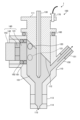
- FIG. 2 is a diagram showing an example of the configuration of a microparticle sorting device according to a first embodiment of the present disclosure.
- the figure is a schematic cross-sectional view showing an example of the configuration of a microparticle sorting device 1. Note that in the microparticle sorting device 1 in the figure, parts other than the droplet generation unit 100 are omitted.
- the droplet generation unit 100 in the figure includes a flow chamber 110, a flow cell 113, a nozzle 114, a sample liquid introduction unit 130, a sample liquid introduction unit holding unit 111, sheath liquid introduction units 120 and 121, and a vibration unit 140.
- the flow chamber 110 ejects droplets 3 from the ejection port 115.
- the flow chamber 110 in the figure is an example formed of a cylindrical housing and has a tapered bottom.
- the ejection port 115 is located at the bottom of the flow chamber 110.
- the sample liquid introduction portion holder 111 which will be described later, is located on the upper surface of the flow chamber 110.
- the sheath fluid introduction sections 120 and 121 are used to introduce sheath fluid into the flow chamber 110.
- the solid oval in the figure represents the sheath fluid introduction section 120.
- the sheath fluid introduction section 120 represents an example in which sheath fluid is introduced from the back side of the paper in the figure.
- the dotted oval in the figure represents the sheath fluid introduction section 121.
- the sheath fluid introduction section 121 represents an example in which sheath fluid is introduced from the front side of the paper in the figure.
- the inside of the flow chamber 110 is filled with sheath fluid (sheath fluid 101).
- the solid arrows in the figure represent the flow of sheath fluid. Details of the configuration of the sheath fluid introduction sections 120 and 121 will be described later.
- the sample liquid introduction section 130 introduces the sample liquid (sample liquid 102) into the flow chamber 110.
- the sample liquid introduction section 130 is configured as a tube inserted into the flow chamber 110, and allows the sample liquid 102 to flow in the direction toward the outlet 115.
- the dotted arrows in the figure represent the flow of the sample liquid 102.
- the sample liquid 102 forms a linear flow downward together with the sheath liquid 101 near the outlet 115.
- the sheath liquid 101 flows in such a way that it envelops the sample liquid 102. This flow of the sheath liquid and sample liquid is called the core flow.
- the sample liquid introduction part holder 111 holds the sample liquid introduction part 130.
- This sample liquid introduction part holder 111 is formed in a disk shape and placed on the upper surface of the flow chamber 110, with the sample liquid introduction part 130 inserted in the center.
- An O-ring 160 for water tightness is placed between the sample liquid introduction part holder 111 and the flow chamber 110.
- the reflector 112 which will be described later, is placed at the bottom of the sample liquid introduction part holder 111.
- the vibration unit 140 applies vibration to the sheath liquid inside the flow chamber 110.
- the vibration unit 140 is inserted into an opening formed in the flow chamber 110 via an O-ring.
- the vibration unit 140 in the figure includes a vibration unit 141, a vibration generating element 142, and a vibration reflecting unit 143.
- the vibration unit 141 is configured in a shape that contacts the sheath liquid 101, and vibrates in a direction that presses the sheath liquid 101 to apply vibration to the sheath liquid 101.
- the vibration generating element 142 vibrates the vibration unit 141.
- the vibration reflecting unit 143 reflects the vibration of the vibration generating element 142 to the vibration unit 141.
- the efficiency of the vibration unit 140 can be improved by arranging the vibration reflecting unit 143.
- the vibration unit 140 vibrates the sheath liquid 101 from a direction different from the introduction direction of the sample liquid 102.
- a wave motion is generated in the sheath liquid 101 due to the vibration of the vibration unit 141 of the vibration unit 140.
- This wave motion of the sheath liquid propagates in a direction different from the core flow described above.
- the vibration unit 140 in the figure shows an example of generating a wave motion of the sheath liquid in a direction perpendicular to the core flow.
- O-rings 161 and 162 can be placed between the vibration part 141 of the vibration part 140 and the housing of the flow chamber 110 in the figure.
- the configuration of the vibration part 140 will be described in detail using Figure 12.
- a reflecting section 112 is disposed at the bottom of the sample liquid introduction section holding section 111 in the figure.
- This reflecting section 112 reflects the wave motion of the sheath liquid 101 generated by the vibration of the vibration section 140 in the direction of the introduction of the sample liquid 102.
- the reflecting section 112 can be configured with a slope inclined with respect to the direction of the introduction of the sample liquid 102.
- the reflecting section 112 in the figure shows an example configured with a slope inclined at 45 degrees with respect to the direction of the introduction of the sample liquid 102.
- the reflecting section 112 can align the direction in which the wave motion of the sheath liquid 101 propagates with the direction of the introduction of the sample liquid 102. This allows the vibration to contribute to the generation of droplets 3 without disturbing the core flow.
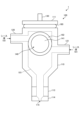
- FIG. 3 is a diagram showing an example of the configuration of a microparticle sorting device according to a first embodiment of the present disclosure.
- the figure is a schematic side view showing an example of the configuration of a microparticle sorting device 1.
- a vibration unit 140 is disposed on the side of the flow chamber 110.
- the figure shows a vibration unit 141 of the vibration unit 140.
- the vibration unit 141 can be configured in a disk shape.
- the sheath fluid introduction parts 120 and 121 are configured to introduce the sheath fluid 101 into the flow chamber 110 from different directions.
- the sheath fluid introduction parts 120 and 121 also introduce the sheath fluid in a direction toward the vibration part 141 in the flow chamber 110.
- the sheath fluid introduction parts 120 and 121 also introduce the sheath fluid in a direction parallel to the normal direction to the surface of the vibration part 141.
- the dashed lines in the figure represent the area of the sheath fluid 101 inside the flow chamber 110.
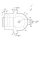
- FIG. 4 is a diagram showing an example of the configuration of a microparticle sorting device according to the first embodiment of the present disclosure.
- This figure is a schematic top view showing an example of the configuration of the microparticle sorting device 1.
- the sheath fluid introduction units 120 and 121 introduce the sheath fluid in a direction toward the vibration unit 141 in the flow chamber 110.
- the dashed line in this figure represents the area of the sheath fluid 101 inside the flow chamber 110.
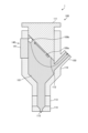
- [Sheath liquid wave] 5 is a diagram showing an example of a wave motion of the sheath liquid according to the first embodiment of the present disclosure.
- the figure shows an example of a wave motion generated by the vibration unit 141 of the vibration unit 140.
- the open arrow in the figure indicates the propagation direction of the wave motion of the sheath liquid 101.
- the wave motion of the sheath liquid 101 formed on the surface of the vibration unit 141 travels straight and reaches the reflecting unit 112.
- the wave motion of the sheath liquid 101 is then reflected by the reflecting unit 112 and becomes a wave motion parallel to the direction of introduction of the sample liquid 102.
- the vibration unit 141 is disposed at the position of the sample liquid introduction unit holding unit 111, and vibrates the sheath liquid 101 parallel to the direction of introduction of the sample liquid 102.
- it is necessary to appropriately transmit the vibration force to the sheath liquid without impeding the introduction of the sample liquid, which makes the configuration of the vibration unit 140 complex.
- a water-stopping structure is required between the vibration unit 140 and the sample liquid introduction unit 130, which makes the configuration of the microparticle sorting device 1 complex.
- Another problem is that it is difficult to replace the sample liquid introduction unit 130 and the sample liquid introduction unit holding unit 111.
- the configuration of the microparticle sorting device 1 can be simplified.
- the vibration section 140 is separated from the sample liquid introduction section holder 111, the sample liquid introduction section 130 and the sample liquid introduction section holder 111 can be easily and inexpensively replaced.
- [Small particle separation method] 6 is a diagram showing an example of a microparticle sorting method according to the first embodiment of the present disclosure.
- the figure is a flow chart showing an example of a microparticle molecular method in the microparticle sorting device 1.
- the sheath fluid 101 is introduced into the flow chamber 110 from the sheath fluid introduction parts 120 and 121 (step S101).
- the sample fluid 102 is introduced into the flow chamber 110 from the sample fluid introduction part 130 (step
- the sheath liquid 101 is vibrated by the vibration unit 140 (step S103). Through the above procedure, the droplets 3 can be generated.
- the microparticle sorting device 1 of the first embodiment of the present disclosure includes a vibration unit 140 that vibrates the sheath liquid 101 in a direction different from the introduction direction of the sample liquid 102. This allows the configuration of the microparticle sorting device 1 to be simplified.
- the sheath fluid inlet portions 120 and 121 for introducing the sheath fluid are disposed in the flow chamber 110.
- the microparticle sorting device 1 of the second embodiment of the present disclosure differs from the first embodiment described above in that a discharge portion for discharging the sheath fluid 101 is disposed in the flow chamber 110.
- FIG. 7 is a diagram showing a configuration example of a microparticle sorting device according to a second embodiment of the present disclosure.
- the diagram is a schematic cross-sectional view showing a configuration example of the microparticle sorting device 1, similar to Fig. 2.
- the microparticle sorting device 1 in the diagram differs from the microparticle sorting device 1 in Fig. 2 in that a discharge unit 150 is disposed in a flow chamber 110.
- the exhaust unit 150 exhausts the sheath fluid 101 in the flow chamber 110.
- This exhaust unit 150 can exhaust bubbles formed in the sheath fluid 101 along with the sheath fluid 101. If bubbles are generated in the sheath fluid 101, the vibration of the sheath fluid 101 by the vibration unit 140 is hindered. Therefore, the exhaust unit 150 is positioned to exhaust the sheath fluid 101 containing the bubbles. This can reduce the effects of the bubbles.
- the discharge part 150 in the figure shows an example in which the sheath fluid 101 is discharged diagonally upward. By arranging the discharge part 150 facing upward like this, bubbles in the discharge part 150 can be prevented from returning to the inside of the flow chamber 110.
- the sheath fluid introduction parts 120 and 121 can also be used as bubble exhaust ports. Specifically, a configuration can be adopted in which sheath fluid containing bubbles is exhausted from the sheath fluid introduction part 121 while sheath fluid is introduced from the sheath fluid introduction part 120 into the flow chamber 110. Also, a configuration can be adopted in which sheath fluid containing bubbles is exhausted from the sheath fluid introduction part 120 while sheath fluid is introduced from the sheath fluid introduction part 121 into the flow chamber 110.
- FIG. 8 is a diagram showing a configuration example of a microparticle sorting device according to a second embodiment of the present disclosure.
- the figure is a schematic top view showing a configuration example of the microparticle sorting device 1, similar to Fig. 4.
- the microparticle sorting device 1 in the figure differs from the microparticle sorting device 1 in Fig. 4 in that it includes a discharge unit 150.
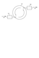
- [Introduction of sheath fluid] 9 is a diagram showing an example of introduction of sheath fluid according to an embodiment of the present disclosure.
- the figure shows an example of introduction of sheath fluid 101 into flow chamber 110 by sheath fluid introduction units 120 and 121.
- the figure shows vibration unit 141 of vibration unit 140, sheath fluid introduction units 120 and 121, and a flow path of sheath fluid 101. Arrows in the figure represent the flow path of sheath fluid 101.
- the sheath fluid introduction units 120 and 121 introduce the sheath fluid in a direction toward the vibration unit 141 in the flow chamber 110. This makes it possible to remove bubbles adhering to the surface of the vibration unit 141.
- the sheath fluid introduction units 120 and 121 are configured to introduce the sheath fluid 101 into the flow chamber 110 from different directions, and introduce the sheath fluid in a direction parallel to the normal direction to the surface of the vibration unit 141. Therefore, a vortex flow of the sheath fluid is formed along the surface of the vibration unit 141. This vortex flow of the sheath fluid makes it possible to remove bubbles adhering to the entire surface of the vibration unit 141. Even if the vibration unit 141 is larger than the sheath fluid introduction units 120 and 121, it is possible to remove bubbles. The bubbles removed from the surface of the vibration unit 141 are discharged from the discharge unit 150.
- FIG. 10 is a diagram showing an example of bubble removal according to the second embodiment of the present disclosure.
- This figure shows an example of bubble removal in the microparticle sorting device 1.
- the sample liquid introduction section 130 and the sheath liquid introduction sections 120 and 121 are omitted in this figure.
- Bubbles 109 are shown in the sheath liquid 101 in this figure.
- the white circles in this figure represent the bubbles 109.
- Fine bubbles 109a are formed in the sheath liquid 101. These bubbles 109a move upward in the sheath liquid 101 and reach the slope of the reflecting section 112. The bubbles 109a then move further along the slope of the reflecting section 112 and gather at the top inside the flow chamber 110.
- the multiple bubbles 109a combine to form a large bubble 109b. Because of their large size, the bubbles 109b are carried along with the sheath liquid 101 and discharged from the discharge section 150.
- the dashed arrow in the figure indicates the discharge path of the bubbles 109b.
- the configuration of the microparticle sorting device 1 is the same as the configuration of the microparticle sorting device 1 in the first embodiment of the present disclosure, so a description thereof will be omitted.
- the microparticle sorting device 1 of the second embodiment of the present disclosure discharges bubbles generated in the sheath liquid 101 in the flow chamber 110 from the discharge section 150. This makes it possible to reduce the effects of the bubbles.
- the microparticle sorting device 1 of the first embodiment described above includes the sample liquid introduction portion holding portion 111.
- the microparticle sorting device 1 of the third embodiment of the present disclosure differs from the first embodiment described above in that the sample liquid introduction portion holding portion 111 is used as a charging portion for the droplets 3.
- FIG. 11 is a diagram showing a configuration example of a microparticle sorting device according to a third embodiment of the present disclosure.
- the figure is a schematic cross-sectional view showing a configuration example of the microparticle sorting device 1, similar to Fig. 2.
- the microparticle sorting device 1 in the figure differs from the microparticle sorting device 1 in Fig. 4 in that an electrode 170 is connected to a sample liquid introduction part holding part 111.
- the droplet generating part 100 in the figure shows an example in which an exhaust pipe 151 connected to an exhaust part 150 is provided.
- an electrode 170 is connected to the sample liquid introduction section holder 111 in the figure.
- This electrode 170 supplies power to impart an electric charge to the droplet 3.
- the sample liquid introduction section holder 111 and the reflector 112 in the figure are made of a conductive material such as metal.
- a charge can be imparted to the droplet 3 by applying a voltage for charging to the sample liquid introduction section holder 111 and the reflector 112 via the electrode 170.
- the electrode 170 can also be connected to the discharge pipe 151. It is also possible to adopt a configuration in which electrodes are provided on both the sample liquid introduction section holder 111 and the discharge pipe 151 to supply power.
- the charging unit 210 of the cell sorter 200 can be omitted.
- the configuration of the microparticle sorting device 1 is the same as the configuration of the microparticle sorting device 1 in the first embodiment of the present disclosure, so a description thereof will be omitted.
- the microparticle sorting device 1 of the third embodiment of the present disclosure uses the sample liquid introduction portion holder 111 and the reflecting portion 112 as a charging portion. This can improve the efficiency of charging the droplets 3.
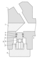
- FIG. 12 is a diagram showing a configuration example of a vibration unit according to an embodiment of the present disclosure.
- the figure is a schematic cross-sectional view showing a vibration unit 140 in the microparticle sorting device 1 of Fig. 1. Note that in the figure, the sample liquid introduction unit 130 and the like are omitted.
- the vibration unit 140 in the figure is fitted with a vibration unit protection unit 145.
- the vibration generating element 142 and vibration reflecting unit 143 in the figure are shown as examples in which they are cylindrical.
- the vibration unit 141 can be made of a ceramic material. This allows the vibration unit 141 to be lightweight and to handle high-frequency vibrations.
- a number of O-rings (O-rings 161 and 162) are arranged between the vibration unit 141 and the housing of the flow chamber 110. By arranging these O-rings, the vibration unit 141 can be attached parallel to the wall surface of the opening (mounting hole) of the housing of the flow chamber 110.
- the vibration part 141 may come into contact with the housing of the flow chamber 110 when the vibration part 140 is attached to the housing of the flow chamber 110 or when the vibration generating element 142 is driven. This may cause the frequency characteristics of the vibration part 141 to change.
- O-rings 161 and 162 sandwiching two O-rings (O-rings 161 and 162) between the vibration part 141 and the housing of the flow chamber 110, a structure can be created in which the vibration part 141 and the housing of the flow chamber 110 do not come into direct contact with each other. This makes it possible to prevent changes in the frequency characteristics of the vibration part 141 during assembly or after the vibration generating element 142 is driven, and makes it possible to stabilize the vibration of the vibration generating element 142. It is preferable to separate the O-rings 161 and 162. This is because it improves the effect of preventing the vibration part 141 from shifting.
- O-rings 161 and 162 can be configured to have different diameters. Specifically, the diameter of O-ring 162, which is located behind vibrating part 141, is made smaller than that of O-ring 161, which is located in front of vibrating part 141. This makes it easier to attach and detach vibration part 140 to and from flow chamber 110.
- the vibration unit 141 with O-rings 161 and 162 is inserted into the opening of the flow chamber 110.
- the action of the O-rings 161 and 162 allows the vibration unit 141 to fit tightly into the opening of the flow chamber 110.
- the O-rings 161 and 162 are made the same diameter and are brought into close contact with the wall of the opening, the clamping force from the wall of the opening will be too strong, making it difficult to attach and remove the vibration unit 140 including the vibration unit 141. Therefore, as described above, O-rings 161 and 162 with different diameters are arranged.
- the O-ring 161 arranged in front of the vibration part 141 plays a role in preventing leakage of the sheath liquid 101, which is subjected to high pressure.
- the O-ring 162 arranged behind the vibration part 141 only needs to prevent leakage of the sheath liquid 101 that has seeped out from the O-ring 161. Therefore, even if an O-ring 162 with a reduced diameter is used, the ability to prevent leakage of the sheath liquid 101 does not decrease. In this way, by arranging the O-rings 161 and 162 of different diameters on the vibration part 141, it is possible to easily attach and replace the vibration part 140 while preventing leakage of the sheath liquid 101 from the attachment part of the vibration part 140.
- the present technology can also be configured as follows. (1) a nozzle that ejects droplets containing a sample liquid and a sheath liquid from an ejection port; a sheath liquid introduction section that introduces the sheath liquid into the nozzle; a sample liquid introduction section that is configured in a tubular shape and inserted into the nozzle, and that introduces the sample liquid in a direction toward the discharge port; a vibration unit that is provided with a vibration unit in contact with the sheath liquid and that vibrates the sheath liquid from a direction different from a direction in which the sample liquid is introduced.
- the microparticle sorting device further comprising a reflecting section that reflects a wave motion of the sheath liquid generated by the vibration of the vibration section in a direction toward which the sample liquid is introduced.
- the reflecting portion has an inclined surface inclined with respect to a direction in which the sample liquid is introduced.
- the reflecting portion has the inclined surface inclined at approximately 45 degrees with respect to a direction in which the sample liquid is introduced.
- the microparticle sorting apparatus is applied with a voltage that charges the droplets.
- the microparticle sorting device according to any one of (1) to (5), wherein the sheath fluid introduction section introduces the sheath fluid in a direction toward the vibration section of the vibration excitation section.
- the microparticle sorting device comprising a plurality of the sheath liquid introduction sections.
- the vibration unit includes a vibration unit having a surface shape that is in contact with the sheath liquid.
- the microparticle sorting device according to (7) above, wherein the plurality of sheath liquid introduction sections each introduce sheath liquid in a direction parallel to a normal direction to a surface of the vibration section and in directions different from each other.
- the microparticle sorting device according to any one of (1) to (8), further comprising an exhaust section for exhausting the sheath liquid from within the nozzle.
- the microparticle sorting apparatus according to (9), wherein the discharge unit discharges the sheath liquid in an obliquely upward direction with respect to a direction in which the sample liquid is introduced.
- the microparticle sorting device according to any one of (1) to (10), wherein the vibration unit is fitted into an opening formed in the nozzle via a plurality of O-rings.
- the microparticle sorting apparatus according to any one of (1) to (11), further comprising a sample liquid introduction section holding section disposed in the droplet generating section and holding the sample liquid introduction section.
Landscapes
- Chemical & Material Sciences (AREA)
- Dispersion Chemistry (AREA)
- Physics & Mathematics (AREA)
- Health & Medical Sciences (AREA)
- Life Sciences & Earth Sciences (AREA)
- Analytical Chemistry (AREA)
- Biochemistry (AREA)
- General Health & Medical Sciences (AREA)
- General Physics & Mathematics (AREA)
- Immunology (AREA)
- Pathology (AREA)
- Engineering & Computer Science (AREA)
- Signal Processing (AREA)
- Separation Of Solids By Using Liquids Or Pneumatic Power (AREA)
- Sampling And Sample Adjustment (AREA)
- Apparatus Associated With Microorganisms And Enzymes (AREA)
Abstract
Description
1.第1の実施形態
2.第2の実施形態
3.第3の実施形態
4.第4の実施形態
[微小粒子分取装置の構成]
図1は、本開示の実施形態に係る微小粒子分取装置の構成例を示す図である。同図は、微小粒子分取装置1の構成例を表す模式図である。微小粒子分取装置1は、流路中に整列させた状態の粒子に光を照射し、各粒子から発せられた光を検出し、検出信号に基づいて前記粒子を内包した液滴に対して、プラス(+)又はマイナス(-)の荷電を付与し、或いは非荷電とし、偏向板によりそれぞれの液滴軌道に分裂させ、目的とする粒子を回収する装置である。微小粒子分取装置1は、液滴生成部100と、光源181と、検出部182と、解析部183と、偏向板190と、回収容器193とを備える。
図5は、本開示の第1の実施形態に係るシース液の波動の一例を示す図である。同図は、加振部140の振動部141により生成される波動の一例を表す図である。同図の白抜きの矢印がシース液101の波動の伝播方向を表す。振動部141の表面において形成されたシース液101の波動は、直進して反射部112に到達する。その後、シース液101の波動は、反射部112により反射され、サンプル液102の導入の方向に平行な波動となる。
図6は、本開示の第1の実施形態に係る微小粒子分取方法の一例を示す図である。同図は、微小粒子分取装置1における微小粒子分子方法の一例を表す流れ図である。まず、シース液導入部120及び121からシース液101がフローチャンバ110内に導入される(ステップS101)。次に、サンプル液導入部130からサンプル液102がフローチャンバ110内に導入される(ステップS102)。次に、加振部140によりシース液101が加振される(ステップS103)。以上の手順により、液滴3を生成することができる。
上述の第1の実施形態の微小粒子分取装置1は、シース液を導入するためのシース液導入部120及び121がフローチャンバ110に配置されていた。これに対し、本開示の第2の実施形態の微小粒子分取装置1は、シース液101を排出する排出部がフローチャンバ110に配置される点で、上述の第1の実施形態と異なる。
図7は、本開示の第2の実施形態に係る微小粒子分取装置の構成例を示す図である。同図は、図2と同様に、微小粒子分取装置1の構成例を表す模式断面図である。同図の微小粒子分取装置1は、フローチャンバ110に排出部150が配置される点で、図2の微小粒子分取装置1と異なる。
図8は、本開示の第2の実施形態に係る微小粒子分取装置の構成例を示す図である。同図は、図4と同様に、微小粒子分取装置1の構成例を表す模式上面図である。同図の微小粒子分取装置1は、排出部150を備える点で、図4の微小粒子分取装置1と異なる。
図9は、本開示の実施形態に係るシース液の導入の一例を示す図である。同図は、シース液導入部120及び121によるフローチャンバ110内へのシース液101の導入の一例を表す図である。同図には、加振部140の振動部141並びにシース液導入部120及び121とシース液101の流路とを記載した。同図の矢印は、シース液101の流路を表す。
図10は、本開示の第2の実施形態に係る泡の除去の一例を示す図である。同図は、微小粒子分取装置1における泡の除去の一例を表す図である。便宜上、同図においてサンプル液導入部130並びにシース液導入部120及び121の記載を省略している。同図のシース液101には泡109を記載した。同図の白抜きの円は、泡109を表す。シース液101には微細な泡109aが形成される。この泡109aは、シース液101内を上方に移動し、反射部112の斜面に達する。その後、泡109aは、反射部112の斜面に沿って更に移動し、フローチャンバ110の内部の最上部に集結する。ここで、複数の泡109aが合体して大きな泡109bが形成される。泡109bは、サイズが大きいため、シース液101とともに流されて排出部150から排出される。同図の破線の矢印は、泡109bの排出経路を表す。
上述の第1の実施形態の微小粒子分取装置1は、サンプル液導入部保持部111を備えていた。これに対し、本開示の第3の実施形態の微小粒子分取装置1は、サンプル液導入部保持部111を液滴3の荷電部として使用する点で、上述の第1の実施形態と異なる。
図11は、本開示の第3の実施形態に係る微小粒子分取装置の構成例を示す図である。同図は、図2と同様に、微小粒子分取装置1の構成例を表す模式断面図である。同図の微小粒子分取装置1は、サンプル液導入部保持部111に電極170が接続される点で、図4の微小粒子分取装置1と異なる。なお、同図の液滴生成部100は、排出部150に接続される排出管151を備える場合の例を表したものである。
加振部140の構成例について説明する。
図12は、本開示の実施形態に係る加振部の構成例を示す図である。同図は、図1の微小粒子分取装置1の内の加振部140の部分を記載した模式断面図である。なお、同図においては、サンプル液導入部130等の記載を省略している。
(1)
サンプル液及びシース液を含む液滴を吐出口より吐出するノズルと、
前記シース液を前記ノズル内に導入するシース液導入部と、
前記ノズル内に挿設された管状に構成されて前記サンプル液を前記吐出口に向かう方向に導入するサンプル液導入部と、
前記シース液に接する振動部を備えて前記サンプル液の導入方向とは異なる方向から前記シース液に加振する加振部と
を有する微小粒子分取装置。
(2)
前記加振部の加振により生成された前記シース液の波動を前記サンプル液の導入の方向に反射する反射部を更に有する前記(1)に記載の微小粒子分取装置。
(3)
前記反射部は、前記サンプル液の導入の方向に対して傾いた斜面を備える前記(2)に記載の微小粒子分取装置。
(4)
前記反射部は、前記サンプル液の導入の方向に対して略45度傾いた前記斜面を備える前記(3)に記載の微小粒子分取装置。
(5)
前記反射部は、前記液滴を帯電させる電圧が印加される前記(2)に記載の微小粒子分取装置。
(6)
前記シース液導入部は、前記加振部の振動部に向かう方向に前記シース液を導入する前記(1)から(5)の何れかに記載の微小粒子分取装置。
(7)
複数の前記シース液導入部を有する前記(6)に記載の微小粒子分取装置。
(8)
前記加振部は、前記シース液に接する面形状の前記振動部を備え、
複数の前記シース液導入部は、前記振動部の面に対する法線方向から見て平行な方向かつ互いに異なる方向にシース液をそれぞれ導入する
前記(7)に記載の微小粒子分取装置。
(9)
前記ノズル内の前記シース液を排出する排出部を更に有する前記(1)から(8)の何れかに記載の微小粒子分取装置。
(10)
前記排出部は、前記サンプル液の導入の方向に対して斜め上方向に前記シース液を排出する前記(9)に記載の微小粒子分取装置。
(11)
前記加振部は、前記ノズルに形成された開口部に複数のOリングを介して嵌挿される前記(1)から(10)の何れかに記載の微小粒子分取装置。
(12)
前記液滴生成部に配置されて前記サンプル液導入部を保持するサンプル液導入部保持部を更に有する前記(1)から(11)の何れかに記載の微小粒子分取装置。
(13)
前記サンプル液導入部保持部は、前記液滴に電荷を付与するための電圧が印加される前記(12)に記載の微小粒子分取装置。
(14)
サンプル液及びシース液を含む液滴を吐出口より吐出するノズル内に前記シース液を導入することと、
前記ノズル内に挿設された管状に構成されて前記サンプル液を前記吐出口に向かう方向に導入するサンプル液導入部から前記サンプル液を導入することと、
前記シース液に接する振動部により前記サンプル液の導入方向とは異なる方向から前記シース液に加振することと
を含む微小粒子分取方法。
3 液滴
100 液滴生成部
101 シース液
102 サンプル液
110 フローチャンバ
111 サンプル液導入部保持部
112 反射部
115 吐出口
120、121 シース液導入部
130 サンプル液導入部
140 加振部
141 振動部
150 排出部
160~162 Oリング
Claims (14)
- 微小粒子を含むサンプル液及びシース液を含む液滴を吐出口より吐出する液滴生成部と、
前記シース液を前記液滴生成部内に導入するシース液導入部と、
前記液滴生成部内に挿設された管状に構成されて前記サンプル液を前記吐出口に向かう方向に導入するサンプル液導入部と、
前記シース液に接する振動部を備え、前記サンプル液の導入方向とは異なる方向から前記シース液に加振する加振部と
を有する微小粒子分取装置。 - 前記加振部の加振により生成された前記シース液の波動を前記サンプル液の導入の方向に反射する反射部を更に有する請求項1に記載の微小粒子分取装置。
- 前記反射部は、前記サンプル液の導入の方向に対して傾いた斜面を備える請求項2に記載の微小粒子分取装置。
- 前記反射部は、前記サンプル液の導入の方向に対して略45度傾いた前記斜面を備える請求項3に記載の微小粒子分取装置。
- 前記反射部は、前記液滴を帯電させる電圧が印加される請求項2に記載の微小粒子分取装置。
- 前記シース液導入部は、前記加振部の振動部に向かう方向に前記シース液を導入する請求項1に記載の微小粒子分取装置。
- 複数の前記シース液導入部を有する請求項6に記載の微小粒子分取装置。
- 前記加振部は、前記シース液に接する面形状の前記振動部を備え、
複数の前記シース液導入部は、前記振動部の面に対する法線方向から見て平行な方向かつ互いに異なる方向にシース液をそれぞれ導入する
請求項7に記載の微小粒子分取装置。 - 前記液滴生成部内の前記シース液を排出する排出部を更に有する請求項1に記載の微小粒子分取装置。
- 前記排出部は、前記サンプル液の導入の方向に対して斜め上方向に前記シース液を排出する請求項9に記載の微小粒子分取装置。
- 前記加振部は、前記液滴生成部に形成された開口部に複数のOリングを介して嵌挿される請求項1に記載の微小粒子分取装置。
- 前記液滴生成部に配置されて前記サンプル液導入部を保持するサンプル液導入部保持部を更に有する請求項1に記載の微小粒子分取装置。
- 前記サンプル液導入部保持部は、前記液滴に電荷を付与するための電圧が印加される請求項12に記載の微小粒子分取装置。
- サンプル液及びシース液を含む液滴を吐出口より吐出する液滴生成部内に前記シース液を導入することと、
前記液滴生成部内に挿設された管状に構成されて前記サンプル液を前記吐出口に向かう方向に導入するサンプル液導入部から前記サンプル液を導入することと、
前記シース液に接する振動部により前記サンプル液の導入方向とは異なる方向から前記シース液に加振することと
を含む微小粒子分取方法。
Priority Applications (3)
| Application Number | Priority Date | Filing Date | Title |
|---|---|---|---|
| EP24819272.6A EP4726363A1 (en) | 2023-06-07 | 2024-05-31 | Microparticle separating device and microparticle separating method |
| JP2025526091A JPWO2024253042A1 (ja) | 2023-06-07 | 2024-05-31 | |
| CN202480035923.2A CN121195154A (zh) | 2023-06-07 | 2024-05-31 | 微粒分选装置和微粒分选方法 |
Applications Claiming Priority (2)
| Application Number | Priority Date | Filing Date | Title |
|---|---|---|---|
| JP2023093631 | 2023-06-07 | ||
| JP2023-093631 | 2023-06-07 |
Publications (1)
| Publication Number | Publication Date |
|---|---|
| WO2024253042A1 true WO2024253042A1 (ja) | 2024-12-12 |
Family
ID=93795972
Family Applications (1)
| Application Number | Title | Priority Date | Filing Date |
|---|---|---|---|
| PCT/JP2024/020070 Ceased WO2024253042A1 (ja) | 2023-06-07 | 2024-05-31 | 微小粒子分取装置及び微小粒子分取方法 |
Country Status (4)
| Country | Link |
|---|---|
| EP (1) | EP4726363A1 (ja) |
| JP (1) | JPWO2024253042A1 (ja) |
| CN (1) | CN121195154A (ja) |
| WO (1) | WO2024253042A1 (ja) |
Citations (3)
| Publication number | Priority date | Publication date | Assignee | Title |
|---|---|---|---|---|
| JPH04208839A (ja) * | 1990-11-30 | 1992-07-30 | Toa Medical Electronics Co Ltd | 粒子検出装置 |
| JP2012137507A (ja) | 1998-02-27 | 2012-07-19 | Beckman Coulter Inc | フローサイトメトリーのための方法および装置 |
| JP2017201278A (ja) * | 2016-05-06 | 2017-11-09 | アライドフロー株式会社 | 生物学的粒子を含む液体フローを形成する装置および処理装置 |
-
2024
- 2024-05-31 CN CN202480035923.2A patent/CN121195154A/zh active Pending
- 2024-05-31 JP JP2025526091A patent/JPWO2024253042A1/ja active Pending
- 2024-05-31 EP EP24819272.6A patent/EP4726363A1/en active Pending
- 2024-05-31 WO PCT/JP2024/020070 patent/WO2024253042A1/ja not_active Ceased
Patent Citations (3)
| Publication number | Priority date | Publication date | Assignee | Title |
|---|---|---|---|---|
| JPH04208839A (ja) * | 1990-11-30 | 1992-07-30 | Toa Medical Electronics Co Ltd | 粒子検出装置 |
| JP2012137507A (ja) | 1998-02-27 | 2012-07-19 | Beckman Coulter Inc | フローサイトメトリーのための方法および装置 |
| JP2017201278A (ja) * | 2016-05-06 | 2017-11-09 | アライドフロー株式会社 | 生物学的粒子を含む液体フローを形成する装置および処理装置 |
Also Published As
| Publication number | Publication date |
|---|---|
| CN121195154A (zh) | 2025-12-23 |
| JPWO2024253042A1 (ja) | 2024-12-12 |
| EP4726363A1 (en) | 2026-04-15 |
Similar Documents
| Publication | Publication Date | Title |
|---|---|---|
| JP5175105B2 (ja) | 粒子を水力学的に仕分けするための方法および装置 | |
| US20250304906A1 (en) | Single-particle analysis method, and system for performing said analysis | |
| CN101609088B (zh) | 微流控芯片和微流控芯片中的送流方法 | |
| JP6136843B2 (ja) | 粒子分取装置、粒子分取方法及びプログラム | |
| KR101683066B1 (ko) | 미소 입자 분취를 위한 장치 및 마이크로칩 | |
| US20110137018A1 (en) | Magnetic separation system with pre and post processing modules | |
| EP2917718B1 (en) | Microparticle fractionating apparatus and method of fractionating microparticle | |
| JP4805415B2 (ja) | 検体識別分取装置および検体識別分取方法 | |
| JP5493486B2 (ja) | 物質混合装置と物質混合方法 | |
| US6881314B1 (en) | Apparatuses and methods for field flow fractionation of particles using acoustic and other forces | |
| US9804075B2 (en) | Particle sorting apparatus, particle sorting method, and non-transitory computer-readable storage medium storing program | |
| EP2743673B1 (en) | Microparticle measurement device and liquid supply method for microparticle measurement device | |
| US7428971B2 (en) | Method for sorting and recovering fine particle and apparatus for recovery | |
| US11738339B2 (en) | Microfluidic devices and method for sampling and analysis of cells using optical forces and Raman spectroscopy | |
| CN110093271B (zh) | 细胞分选装置 | |
| JP2017122734A (ja) | 粒子分取装置、粒子分取方法及びプログラム | |
| EP4726363A1 (en) | Microparticle separating device and microparticle separating method | |
| JP2019063798A (ja) | 粒子分取装置、粒子分取方法及びプログラム | |
| WO2002059598A1 (en) | Method and apparatus for the precise positioning of cells and other small objects | |
| JP4745755B2 (ja) | 分画マイクロチップ及び分画装置 | |
| WO2015111293A1 (ja) | 粒子分取装置及び粒子分取方法 | |
| JP2006043500A (ja) | 粒子分別採取装置およびその採取方法 | |
| CN116134304B (zh) | 微粒分选装置及微粒分选方法 | |
| WO2023238564A1 (ja) | 情報処理システム、情報処理方法、情報処理装置、及びプログラム | |
| JPH074222B2 (ja) | 細胞破砕選別装置及び選択的遺伝子導入装置 |
Legal Events
| Date | Code | Title | Description |
|---|---|---|---|
| 121 | Ep: the epo has been informed by wipo that ep was designated in this application |
Ref document number: 24819272 Country of ref document: EP Kind code of ref document: A1 |
|
| ENP | Entry into the national phase |
Ref document number: 2025526091 Country of ref document: JP Kind code of ref document: A |
|
| WWE | Wipo information: entry into national phase |
Ref document number: 2025526091 Country of ref document: JP |
|
| WWE | Wipo information: entry into national phase |
Ref document number: 2024819272 Country of ref document: EP |
|
| NENP | Non-entry into the national phase |
Ref country code: DE |
|
| ENP | Entry into the national phase |
Ref document number: 2024819272 Country of ref document: EP Effective date: 20260107 |
|
| ENP | Entry into the national phase |
Ref document number: 2024819272 Country of ref document: EP Effective date: 20260107 |
|
| ENP | Entry into the national phase |
Ref document number: 2024819272 Country of ref document: EP Effective date: 20260107 |
|
| ENP | Entry into the national phase |
Ref document number: 2024819272 Country of ref document: EP Effective date: 20260107 |
|
| ENP | Entry into the national phase |
Ref document number: 2024819272 Country of ref document: EP Effective date: 20260107 |
|
| WWP | Wipo information: published in national office |
Ref document number: 2024819272 Country of ref document: EP |