WO2024253058A1 - 歯垢検出装置、歯垢検出方法及びプログラム - Google Patents
歯垢検出装置、歯垢検出方法及びプログラム Download PDFInfo
- Publication number
- WO2024253058A1 WO2024253058A1 PCT/JP2024/020180 JP2024020180W WO2024253058A1 WO 2024253058 A1 WO2024253058 A1 WO 2024253058A1 JP 2024020180 W JP2024020180 W JP 2024020180W WO 2024253058 A1 WO2024253058 A1 WO 2024253058A1
- Authority
- WO
- WIPO (PCT)
- Prior art keywords
- plaque
- image
- rgb image
- tartar
- pixels
- Prior art date
- Legal status (The legal status is an assumption and is not a legal conclusion. Google has not performed a legal analysis and makes no representation as to the accuracy of the status listed.)
- Ceased
Links
Images


Classifications
-
- A—HUMAN NECESSITIES
- A61—MEDICAL OR VETERINARY SCIENCE; HYGIENE
- A61B—DIAGNOSIS; SURGERY; IDENTIFICATION
- A61B1/00—Instruments for performing medical examinations of the interior of cavities or tubes of the body by visual or photographical inspection, e.g. endoscopes; Illuminating arrangements therefor
- A61B1/04—Instruments for performing medical examinations of the interior of cavities or tubes of the body by visual or photographical inspection, e.g. endoscopes; Illuminating arrangements therefor combined with photographic or television appliances
- A61B1/043—Instruments for performing medical examinations of the interior of cavities or tubes of the body by visual or photographical inspection, e.g. endoscopes; Illuminating arrangements therefor combined with photographic or television appliances for fluorescence imaging
-
- A—HUMAN NECESSITIES
- A61—MEDICAL OR VETERINARY SCIENCE; HYGIENE
- A61B—DIAGNOSIS; SURGERY; IDENTIFICATION
- A61B1/00—Instruments for performing medical examinations of the interior of cavities or tubes of the body by visual or photographical inspection, e.g. endoscopes; Illuminating arrangements therefor
- A61B1/00002—Operational features of endoscopes
- A61B1/00004—Operational features of endoscopes characterised by electronic signal processing
- A61B1/00009—Operational features of endoscopes characterised by electronic signal processing of image signals during a use of endoscope
- A61B1/000094—Operational features of endoscopes characterised by electronic signal processing of image signals during a use of endoscope extracting biological structures
-
- A—HUMAN NECESSITIES
- A61—MEDICAL OR VETERINARY SCIENCE; HYGIENE
- A61B—DIAGNOSIS; SURGERY; IDENTIFICATION
- A61B1/00—Instruments for performing medical examinations of the interior of cavities or tubes of the body by visual or photographical inspection, e.g. endoscopes; Illuminating arrangements therefor
- A61B1/00002—Operational features of endoscopes
- A61B1/00004—Operational features of endoscopes characterised by electronic signal processing
- A61B1/00009—Operational features of endoscopes characterised by electronic signal processing of image signals during a use of endoscope
- A61B1/000095—Operational features of endoscopes characterised by electronic signal processing of image signals during a use of endoscope for image enhancement
-
- A—HUMAN NECESSITIES
- A61—MEDICAL OR VETERINARY SCIENCE; HYGIENE
- A61B—DIAGNOSIS; SURGERY; IDENTIFICATION
- A61B1/00—Instruments for performing medical examinations of the interior of cavities or tubes of the body by visual or photographical inspection, e.g. endoscopes; Illuminating arrangements therefor
- A61B1/00064—Constructional details of the endoscope body
- A61B1/00071—Insertion part of the endoscope body
- A61B1/0008—Insertion part of the endoscope body characterised by distal tip features
- A61B1/00096—Optical elements
-
- A—HUMAN NECESSITIES
- A61—MEDICAL OR VETERINARY SCIENCE; HYGIENE
- A61B—DIAGNOSIS; SURGERY; IDENTIFICATION
- A61B1/00—Instruments for performing medical examinations of the interior of cavities or tubes of the body by visual or photographical inspection, e.g. endoscopes; Illuminating arrangements therefor
- A61B1/00163—Optical arrangements
- A61B1/00186—Optical arrangements with imaging filters
-
- A—HUMAN NECESSITIES
- A61—MEDICAL OR VETERINARY SCIENCE; HYGIENE
- A61B—DIAGNOSIS; SURGERY; IDENTIFICATION
- A61B1/00—Instruments for performing medical examinations of the interior of cavities or tubes of the body by visual or photographical inspection, e.g. endoscopes; Illuminating arrangements therefor
- A61B1/04—Instruments for performing medical examinations of the interior of cavities or tubes of the body by visual or photographical inspection, e.g. endoscopes; Illuminating arrangements therefor combined with photographic or television appliances
- A61B1/045—Control thereof
-
- A—HUMAN NECESSITIES
- A61—MEDICAL OR VETERINARY SCIENCE; HYGIENE
- A61B—DIAGNOSIS; SURGERY; IDENTIFICATION
- A61B1/00—Instruments for performing medical examinations of the interior of cavities or tubes of the body by visual or photographical inspection, e.g. endoscopes; Illuminating arrangements therefor
- A61B1/04—Instruments for performing medical examinations of the interior of cavities or tubes of the body by visual or photographical inspection, e.g. endoscopes; Illuminating arrangements therefor combined with photographic or television appliances
- A61B1/05—Instruments for performing medical examinations of the interior of cavities or tubes of the body by visual or photographical inspection, e.g. endoscopes; Illuminating arrangements therefor combined with photographic or television appliances characterised by the image sensor, e.g. camera, being in the distal end portion
-
- A—HUMAN NECESSITIES
- A61—MEDICAL OR VETERINARY SCIENCE; HYGIENE
- A61B—DIAGNOSIS; SURGERY; IDENTIFICATION
- A61B1/00—Instruments for performing medical examinations of the interior of cavities or tubes of the body by visual or photographical inspection, e.g. endoscopes; Illuminating arrangements therefor
- A61B1/06—Instruments for performing medical examinations of the interior of cavities or tubes of the body by visual or photographical inspection, e.g. endoscopes; Illuminating arrangements therefor with illuminating arrangements
- A61B1/0661—Endoscope light sources
- A61B1/0676—Endoscope light sources at distal tip of an endoscope
-
- A—HUMAN NECESSITIES
- A61—MEDICAL OR VETERINARY SCIENCE; HYGIENE
- A61B—DIAGNOSIS; SURGERY; IDENTIFICATION
- A61B1/00—Instruments for performing medical examinations of the interior of cavities or tubes of the body by visual or photographical inspection, e.g. endoscopes; Illuminating arrangements therefor
- A61B1/06—Instruments for performing medical examinations of the interior of cavities or tubes of the body by visual or photographical inspection, e.g. endoscopes; Illuminating arrangements therefor with illuminating arrangements
- A61B1/0661—Endoscope light sources
- A61B1/0684—Endoscope light sources using light emitting diodes [LED]
-
- A—HUMAN NECESSITIES
- A61—MEDICAL OR VETERINARY SCIENCE; HYGIENE
- A61B—DIAGNOSIS; SURGERY; IDENTIFICATION
- A61B1/00—Instruments for performing medical examinations of the interior of cavities or tubes of the body by visual or photographical inspection, e.g. endoscopes; Illuminating arrangements therefor
- A61B1/24—Instruments for performing medical examinations of the interior of cavities or tubes of the body by visual or photographical inspection, e.g. endoscopes; Illuminating arrangements therefor for the mouth, i.e. stomatoscopes, e.g. with tongue depressors; Instruments for opening or keeping open the mouth
-
- A—HUMAN NECESSITIES
- A61—MEDICAL OR VETERINARY SCIENCE; HYGIENE
- A61B—DIAGNOSIS; SURGERY; IDENTIFICATION
- A61B5/00—Measuring for diagnostic purposes; Identification of persons
- A61B5/0059—Measuring for diagnostic purposes; Identification of persons using light, e.g. diagnosis by transillumination, diascopy, fluorescence
- A61B5/0071—Measuring for diagnostic purposes; Identification of persons using light, e.g. diagnosis by transillumination, diascopy, fluorescence by measuring fluorescence emission
-
- A—HUMAN NECESSITIES
- A61—MEDICAL OR VETERINARY SCIENCE; HYGIENE
- A61B—DIAGNOSIS; SURGERY; IDENTIFICATION
- A61B5/00—Measuring for diagnostic purposes; Identification of persons
- A61B5/0059—Measuring for diagnostic purposes; Identification of persons using light, e.g. diagnosis by transillumination, diascopy, fluorescence
- A61B5/0082—Measuring for diagnostic purposes; Identification of persons using light, e.g. diagnosis by transillumination, diascopy, fluorescence adapted for particular medical purposes
- A61B5/0088—Measuring for diagnostic purposes; Identification of persons using light, e.g. diagnosis by transillumination, diascopy, fluorescence adapted for particular medical purposes for oral or dental tissue
Definitions
- This disclosure relates to a plaque detection device, a plaque detection method, and a program.
- Patent document 1 discloses a device that detects plaque based on photographs taken of teeth inside the oral cavity.
- plaque detection devices It is desirable for such plaque detection devices to be able to detect the condition of plaque in more detail.
- the present disclosure therefore provides a plaque detection device or method that can detect the condition of teeth in detail.
- a plaque detection device includes an acquisition unit that acquires a first RGB image from reflected light and fluorescence from teeth, plaque, and tartar in an oral cavity irradiated with irradiation light of a predetermined wavelength that excites fluorescent substances contained in plaque and tartar, and generates a second RGB image by performing image processing including a first image processing on the first RGB image, and detects the content per unit area of the fluorescent substances contained in the plaque and tartar attached to the teeth based on the fluorescence intensity value of the fluorescent reaction of the fluorescent substances in the second RGB image.
- the first image processing is a process of extracting a natural tooth region free of plaque and tartar from the first RGB image, and adjusting the gain of at least two color components of the red, green, and blue components of the first RGB image so that a first red pixel average value of multiple red pixel values of multiple first pixels constituting the natural tooth region, a first green pixel average value of multiple green pixel values of the multiple first pixels, and a first blue pixel average value of multiple blue pixel values of the multiple first pixels are equal.
- the present disclosure can provide a plaque detection device or method that can detect the condition of teeth in detail.
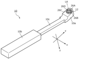
- FIG. 1 is a perspective view of an intraoral camera in an intraoral camera system according to an embodiment.
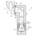
- FIG. 2 is a cross-sectional view illustrating a schematic imaging optical system incorporated in the intraoral camera in the intraoral camera system according to the embodiment.
- FIG. 3 is a schematic configuration diagram of an intraoral camera system according to an embodiment.
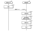
- FIG. 4 is a diagram showing an operation flow of the intraoral camera system according to the embodiment.
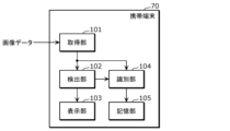
- FIG. 5 is a functional block diagram of a mobile terminal according to an embodiment.
- FIG. 6 is a diagram showing an example of teeth in an oral cavity according to an embodiment.
- FIG. 7 is a diagram illustrating an example of a layered model according to the embodiment.
- FIG. 8 is a diagram for explaining the illuminance of fluorescent light at a depth D according to the embodiment.
- FIG. 9 is a diagram for explaining the illuminance of fluorescent light observed from dental plaque having a thickness D0 according to the embodiment.
- FIG. 10 is a flowchart of a process for detecting the concentration distribution of a fluorescent material according to the embodiment.
- FIG. 11 is a diagram showing an example of a fourth RGB image according to the embodiment.
- FIG. 12 is a diagram showing an example of a fourth RGB image according to the embodiment.
- FIG. 13 is a diagram showing the relationship between the fluorescence intensity, MIN, and k according to the embodiment.
- FIG. 14 is a diagram showing the relationship between the fluorescence intensity, S (saturation), and k according to the embodiment.
- FIG. 15 is a diagram showing the relationship between the fluorescence intensity, L (brightness), and k according to the embodiment.
- FIG. 16 is a diagram showing an example of pixel values in each image when the blue light region is attenuated by the signal processing according to the embodiment.
- FIG. 17 is a diagram showing an example of pixel values in each image when the blue light region is attenuated by the signal processing according to the embodiment.
- a plaque detection device includes an acquisition unit that acquires a first RGB image from reflected light and fluorescence from teeth, plaque, and tartar in an oral cavity irradiated with irradiation light of a predetermined wavelength that excites fluorescent substances contained in plaque and tartar, and generates a second RGB image by performing image processing including a first image processing on the first RGB image, and detects the content per unit area of the fluorescent substances contained in the plaque and tartar attached to the teeth based on the fluorescence intensity value of the fluorescent reaction of the fluorescent substances in the second RGB image.
- the first image processing is a process for extracting a natural tooth region free of plaque or tartar from the first RGB image, and adjusting the gain of at least two color components of the red, green, and blue components of the first RGB image so that a first red pixel average value of multiple red pixel values of multiple first pixels constituting the natural tooth region, a first green pixel average value of multiple green pixel values of the multiple first pixels, and a first blue pixel average value of multiple blue pixel values of the multiple first pixels are equal.
- the plaque detection device can detect the amount of fluorescent substance contained in plaque and tartar attached to the teeth per unit area, thereby enabling detailed detection of the condition of the teeth. Furthermore, by performing the first image processing, the plaque detection device can adjust the white balance of the first RGB image in which the fluorescently reacting teeth are photographed. As a result, the plaque detection device can generate a second RGB image that makes it easy to distinguish the plaque region, which is the region on the tooth where plaque is attached. Therefore, the plaque detection device can improve the detection accuracy of the amount of fluorescent substance contained in plaque and tartar attached to the teeth per unit area. Furthermore, the plaque detection device can improve the accuracy of the white balance adjustment process by performing the first image processing using pixels of the natural tooth region where plaque and tartar are not attached.
- a first region may be detected in which (i) in the entire pixel region of the first RGB image, the luminance value is equal to or greater than a predetermined first threshold value, or (ii) in the entire pixel region of the first RGB image, the green pixel value is equal to or greater than a predetermined second threshold value, and the natural tooth region may be extracted based on the first region.
- the plaque detection device can accurately detect the natural tooth region using the luminance value or the green pixel value.
- an area obtained by excluding areas of plaque and tartar from the first region may be extracted as the natural tooth region. This allows the plaque detection device to improve the accuracy of the white balance adjustment process.
- the first RGB image may be an image in which at least a portion of the blue light region is attenuated from the reflected light and fluorescence from the teeth and plaque in the oral cavity.
- the plaque detection device can improve the detection accuracy of the content per unit area of fluorescent substances contained in plaque and tartar attached to the teeth by using a first image in which at least a portion of the blue light region is attenuated from the reflected light and fluorescence from the teeth, plaque, and tartar in the oral cavity irradiated with irradiation light of a predetermined wavelength that excites fluorescent substances contained in plaque and tartar.
- the detection unit may generate an HSV image from the second RGB image, and detect the amount of fluorescent material contained in the plaque and tartar adhering to the teeth per unit area from the brightness value of the HSV image.
- the plaque detection device can accurately detect the amount of fluorescent material contained in the plaque and tartar adhering to the teeth per unit area based on the brightness value of the HSV image.
- the detection unit may identify a specific pixel area in which one or more fourth pixels of the HSV image that have saturation within a first predetermined range, hue within a second predetermined range, and brightness within at least one of a third predetermined range are located, and detect the amount of the fluorescent substance contained in the plaque and tartar attached to the tooth per unit area from the brightness value in the specific pixel area.
- the plaque detection device can improve the detection accuracy of the amount by detecting the amount of the fluorescent substance contained in the plaque and tartar attached to the tooth per unit area after identifying the plaque area in the tooth image.
- the detection unit may generate an HSL image from the second RGB image, and detect the amount of fluorescent material contained in the plaque and tartar adhering to the teeth per unit area from the luminance value of the HSL image.
- the plaque detection device can accurately detect the amount of fluorescent material contained in the plaque and tartar adhering to the teeth per unit area based on the luminance value of the HSL image.
- the detection unit may identify a specific pixel area in which one or more fifth pixels of the HSL image that have at least one of a saturation within a fourth predetermined range, a hue within a fifth predetermined range, and a luminance within a sixth predetermined range are located, and detect the amount of the fluorescent substance contained in the plaque and tartar attached to the tooth per unit area from the luminance value in the specific pixel area.
- the plaque detection device can improve the detection accuracy of the amount by detecting the amount of the fluorescent substance contained in the plaque and tartar attached to the tooth per unit area after identifying the plaque area in the tooth image.
- the fluorescent substance may be porphyrin.
- the detection unit may assign the content per unit area of the fluorescent substance contained in the plaque and tartar attached to the tooth to three or more gradations, and generate a third image by superimposing the content per unit area of the fluorescent substance contained in the plaque and tartar attached to the tooth displayed in gradations on a second image based on the first RGB image. In this way, for example, the generated third image can notify the user of the content per unit area of the fluorescent substance contained in the plaque and tartar attached to the tooth.
- the plaque detection device may further include an identification unit that identifies the type of photographed tooth, and a storage unit that stores the amount of fluorescent substance contained in the plaque and tartar adhering to the tooth detected from the photographed tooth per unit area in association with the identified type of tooth. In this way, the plaque detection device can manage the amount of fluorescent substance contained in the plaque and tartar adhering to each tooth per unit area.
- a plaque detection method includes obtaining a first RGB image from reflected light and fluorescence from teeth, plaque, and tartar in an oral cavity irradiated with irradiation light of a predetermined wavelength that excites fluorescent substances contained in plaque and tartar, performing image processing including a first image processing on the first RGB image to generate a second RGB image, and calculating the content per unit area of the fluorescent substances contained in the plaque and tartar attached to the teeth based on the value of the fluorescence intensity of the fluorescent reaction of the fluorescent substances in the second RGB image.
- the first image processing is a process of extracting a natural tooth region free of plaque and tartar from the first RGB image, and adjusting the gain of at least two of the red, green, and blue color components of the first RGB image so that a first red pixel average value of multiple red pixel values of multiple first pixels constituting the natural tooth region, a first green pixel average value of multiple green pixel values of the multiple first pixels, and a first blue pixel average value of multiple blue pixel values of the multiple first pixels are equal.
- the plaque detection method can detect the amount of fluorescent substance contained in plaque and tartar attached to the teeth per unit area, and thus can detect the condition of the teeth in detail. Furthermore, the plaque detection method can adjust the white balance of the first RGB image in which the fluorescently reacting teeth are photographed by performing the first image processing. Therefore, the plaque detection method can generate a second RGB image that makes it easy to distinguish the plaque region, which is the region of the tooth where plaque is attached. Therefore, the plaque detection method can improve the detection accuracy of the amount of fluorescent substance contained in plaque and tartar attached to the teeth per unit area. Furthermore, the plaque detection method can improve the accuracy of the white balance adjustment process by performing the first image processing using pixels of the natural tooth region where plaque and tartar are not attached.
- a program according to one aspect of the present disclosure is a program for causing a computer to execute the plaque detection method.
- FIG. 1 is a perspective view of an intraoral camera in an intraoral camera system according to the present embodiment.
- an intraoral camera 10 has a toothbrush-like housing that can be handled with one hand, and the housing includes a head portion 10a that is placed in a user's oral cavity when photographing a dentition, a handle portion 10b that the user holds, and a neck portion 10c that connects the head portion 10a and the handle portion 10b.
- FIG 2 is a cross-sectional view that shows a schematic of the imaging optical system 12 incorporated in the intraoral camera 10.
- the imaging optical system 12 of the intraoral camera 10 is incorporated in the head portion 10a and the neck portion 10c.
- the imaging optical system 12 includes an image sensor 14 and a lens 16 arranged on its optical axis LA.
- the imaging element 14 is a photographing device such as a C-MOS (Complementary Metal-Oxide-Semiconductor) sensor or a CCD (Charge Coupled Device) element, and an image of the tooth D is formed by the lens 16.
- the imaging element 14 outputs a signal (image data) corresponding to the formed image to the outside.
- the lens 16 is, for example, a focusing lens, and forms an image of the tooth D that is incident on the imaging element 14.
- the lens 16 may be a single lens or a lens group consisting of multiple lenses.
- the imaging optical system 12 further includes a mirror 18 that reflects the image of the tooth D toward the lens 16, a blue light cut filter (blue light blocking element) 20 arranged between the mirror 18 and the lens 16, and an aperture 24 arranged between the lens 16 and the image sensor 14.
- a mirror 18 that reflects the image of the tooth D toward the lens 16
- a blue light cut filter (blue light blocking element) 20 arranged between the mirror 18 and the lens 16
- an aperture 24 arranged between the lens 16 and the image sensor 14.
- the mirror 18 is positioned on the optical axis LA of the imaging optical system 12 so as to reflect the image of the tooth D that passes through the entrance 12a of the imaging optical system 12 toward the lens 16.
- the blue light cut filter 20 is a filter that cuts out the blue wavelength light components contained in the light that enters the image sensor 14.
- the blue light cut filter 20 cuts out light including the blue wavelength range from the light before it enters the image sensor 14.
- the aperture 24 is a plate-shaped member with a through hole on the optical axis LA of the imaging optical system 12, and achieves a deep focal depth. This allows the focus to be adjusted in the depth direction within the oral cavity, and an image of the dentition with clear contours can be obtained.
- the intraoral camera 10 is also equipped with a number of first to fourth LEDs 26A to 26D as lighting devices that irradiate light onto the tooth D to be photographed during photography.
- the first to fourth LEDs 26A to 26D are, for example, blue LEDs (Light Emitting Diodes). As shown in FIG. 1, in this embodiment, the first to fourth LEDs 26A to 26D are arranged to surround the entrance 12a.
- a translucent cover 28 that covers the first to fourth LEDs 26A to 26D and the entrance 12a is provided on the head portion 10a to prevent the gums G, etc. from coming into contact with the first to fourth LEDs 26A to 26D and causing a shortage of illumination light.
- Some of the first to fourth LEDs 26A to 26D may be white LEDs. By using white LEDs for some of the first through fourth LEDs 26A-26D, the first RGB image can be brightened and the balance of blue pixel values relative to red and green pixel values can be improved.
- the intraoral camera 10 has a composition adjustment mechanism 30 and a focus adjustment mechanism 32, as shown in FIG. 2.
- the composition adjustment mechanism 30 is composed of a housing 34 that holds the image sensor 14 and lens 16, and an actuator 36 that moves the housing 34 in the direction in which the optical axis LA extends.
- the actuator 36 adjusts the position of the housing 34 to adjust the angle of view, i.e., the size of the row of teeth imaged on the image sensor 14.
- the composition adjustment mechanism 30 automatically adjusts the position of the housing 34 so that, for example, an entire tooth is captured in the captured image.
- the composition adjustment mechanism 30 also adjusts the position of the housing 34 based on the user's operation so that the angle of view desired by the user is achieved.
- the focus adjustment mechanism 32 is held within the housing 34 of the composition adjustment mechanism 30 and is composed of a lens holder 38 that holds the lens 16, and an actuator 40 that moves the lens holder 38 in the extension direction of the optical axis LA.
- the actuator 40 adjusts the relative position of the lens holder 38 with respect to the image sensor 14, thereby adjusting the focus, i.e., the focal point.
- the focus adjustment mechanism 32 automatically adjusts the position of the lens holder 38 so that, for example, a tooth located in the center of the captured image is brought into focus.
- the focus adjustment mechanism 32 also adjusts the position of the lens holder 38 based on the user's operation.
- the components of the imaging optical system 12, except for the mirror 18, may be provided on the handle portion 10b of the intraoral camera 10.
- the image output by the imaging element 14 is an RGB image in which each of the multiple pixels that make up the image has RGB sub-pixels.
- the intraoral camera 10 is also equipped with multiple first to fourth LEDs 26A to 26D as lighting devices that irradiate light onto the teeth to be photographed during photography.
- the first to fourth LEDs 26A to 26D are, for example, blue LEDs that irradiate blue light with a wavelength that peaks at 405 nm. Note that the first to fourth LEDs 26A to 26D are not limited to blue LEDs and may be any light source that irradiates light that includes the wavelength range of blue light.
- FIG. 3 is a schematic diagram of an intraoral camera system according to this embodiment.
- the intraoral camera system according to this embodiment is generally configured to capture an image of the dentition using an intraoral camera 10 and perform image processing on the captured image.
- the intraoral camera system includes an intraoral camera 10, a mobile terminal 70, and a cloud server 80.
- the mobile terminal 70 is, for example, a smartphone or tablet terminal capable of wireless communication.
- the mobile terminal 70 is equipped with, as an input device and an output device, a touch screen 72 capable of displaying, for example, an image of a dentition.
- the mobile terminal 70 functions as a user interface for the intraoral camera system.
- the cloud server 80 is a server that can communicate with the mobile terminal 70 via the Internet or the like, and provides the mobile terminal 70 with an application for using the intraoral camera 10. For example, a user downloads an application from the cloud server 80 and installs it on the mobile terminal 70. The cloud server 80 also acquires dentition images captured by the intraoral camera 10 via the mobile terminal 70.
- the intraoral camera 10 includes a central control unit 50 as the main part that controls the system, an LED control unit 54 that controls the multiple LEDs 26A-26D, a lens driver 56 that controls the actuator 36 of the composition adjustment mechanism 30 and the actuator 40 of the focus adjustment mechanism 32, and a position sensor 90.
- the intraoral camera 10 also has a wireless communication module 58 that communicates wirelessly with the mobile terminal 70, and a power supply control unit 60 that supplies power to the central control unit 50 and other components.
- the central control unit 50 of the intraoral camera 10 is mounted, for example, on the handle unit 10b of the intraoral camera 10.
- the central control unit 50 also includes a controller 62 such as a CPU (Central Processing Unit) or MPU (Micro Processing Unit) that executes various processes described below, and a memory 64 such as a RAM (Random Access Memory) or ROM (Read Only Memory) that stores programs for causing the controller 62 to execute various processes.
- the memory 64 also stores a dentition image (image data) captured by the imaging element 14 and various setting data.
- the dentition image captured by the imaging element 14 is an example of a first RGB image.
- the controller 62 transmits the dentition image output from the imaging element 14 to the mobile terminal 70 via the wireless communication module 58.
- the mobile terminal 70 displays the transmitted dentition image on the touch screen 72, thereby presenting the dentition image to the user.
- the LED control unit 54 is mounted, for example, on the handle portion 10b of the intraoral camera 10, and turns on and off the first to fourth LEDs 26A to 26D based on a control signal from the controller 62.
- the LED control unit 54 is composed of, for example, a circuit. For example, when a user performs an operation on the touch screen 72 of the mobile terminal 70 to start the intraoral camera 10, a corresponding signal is sent from the mobile terminal 70 to the controller 62 via the wireless communication module 58. Based on the received signal, the controller 62 sends a control signal to the LED control unit 54 to turn on the first to fourth LEDs 26A to 26D.
- the lens driver 56 is mounted, for example, on the handle portion 10b of the intraoral camera 10, and controls the actuator 36 of the composition adjustment mechanism 30 and the actuator 40 of the focus adjustment mechanism 32 based on a control signal from the controller 62 of the central control unit 50.
- the lens driver 56 is, for example, composed of a circuit.
- a corresponding signal is transmitted from the mobile terminal 70 to the central control unit 50 via the wireless communication module 58.
- the controller 62 of the central control unit 50 transmits a control signal to the lens driver 56 to perform composition adjustment or focus adjustment.
- the controller 62 calculates the control amount of the actuator 36 or 40 required for composition adjustment or focus adjustment based on the dentition image from the imaging element 14, and a control signal corresponding to the calculated control amount is transmitted to the lens driver 56.
- the wireless communication module 58 is mounted, for example, on the handle portion 10b of the intraoral camera 10, and performs wireless communication with the mobile terminal 70 based on a control signal from the controller 62.
- the wireless communication module 58 performs wireless communication with the mobile terminal 70 that complies with existing communication standards such as WiFi (registered trademark) or Bluetooth (registered trademark).
- WiFi registered trademark
- Bluetooth registered trademark
- the power supply control unit 60 is mounted on the handle portion 10b of the intraoral camera 10, and distributes power from a battery 66 to the central control unit 50, the LED control unit 54, the lens driver 56, and the wireless communication module 58.
- the power supply control unit 60 is composed of, for example, a circuit.
- the battery 66 is a rechargeable secondary battery, and is wirelessly charged by an external charger 69 connected to a commercial power source via a coil 68 mounted on the intraoral camera 10.
- the position sensor 90 is a sensor for detecting the posture and position of the intraoral camera 10, and is, for example, a multi-axis (here, three axes: x, y, and z) acceleration sensor.
- the position sensor 90 may be a six-axis sensor having a three-axis acceleration sensor and a three-axis gyro sensor.
- the z-axis coincides with the optical axis LA.
- the y-axis is parallel to the imaging surface and extends in the longitudinal direction of the intraoral camera 10.
- the x-axis is parallel to the imaging surface and perpendicular to the y-axis.
- the output of each axis of the position sensor 90 may be transmitted to the mobile terminal 70 via the central control unit 50 and the wireless communication module 58.
- the position sensor 90 may be a piezoresistance type, capacitance type, or heat detection type MEMS (Micro Electro Mechanical Systems) sensor.
- a correction circuit may be provided to correct the balance of sensitivity of the sensors for each axis, the temperature characteristics of sensitivity, or temperature drift.
- a band-pass filter (low-pass filter) may also be provided to remove dynamic acceleration components or noise. Noise may also be reduced by smoothing the output waveform of the acceleration sensor.
- Figure 4 is a diagram showing the flow of operation in the intraoral camera system. Note that the process shown in Figure 4 is, for example, a process that is performed in real time, and is performed each time one frame or multiple frames of image data are obtained.
- Image data is generated when a user uses the intraoral camera 10 to capture images of the teeth and gums in their oral cavity (S101). This image data is obtained, for example, by irradiating the teeth with light including a wavelength range of blue light and capturing images of the teeth that are undergoing a fluorescent reaction.
- the intraoral camera 10 transmits the captured image data to the mobile terminal 70 (S102).
- the image data may be a video or one or more still images.
- the sensor data may be transmitted for each frame of the video or for each still image.
- the image data is a video, the sensor data may be transmitted for each multiple frames.
- image data may be transmitted in real time, or may be transmitted all at once after a series of photographs (e.g., photographs of all teeth in the oral cavity) have been taken.
- the mobile terminal 70 performs image processing on the received image data (S103), and detects the concentration distribution of the fluorescent substance using the processed image data (S104). Next, the mobile terminal 70 generates an image in which the detected concentration distribution of the fluorescent substance is superimposed on an image of the oral cavity (S105), and displays the generated image (S106).
- the user can take an image of the inside of their own oral cavity with the intraoral camera 10 and check the condition of the oral cavity displayed on the mobile terminal 70. Furthermore, the concentration distribution of the fluorescent substance is shown in the displayed image, so that the user can easily check the health condition of their own teeth.
- the mobile terminal 70 may also generate a three-dimensional model of multiple teeth in the oral cavity from multiple captured image data.
- the mobile terminal 70 may also display an image based on the generated three-dimensional model.
- the mobile terminal 70 processes images of teeth, some or all of this processing may be performed by the intraoral camera 10.
- the mobile terminal 70 is an example of a plaque detection device.
- FIG. 5 is a functional block diagram of the mobile terminal 70.
- the mobile terminal 70 includes an acquisition unit 101, a detection unit 102, a display unit 103, an identification unit 104, and a storage unit 105.
- the acquisition unit 101 acquires image data (first RGB image) transmitted from the intraoral camera 10.
- the acquisition unit 101 may acquire sensor data in addition to image data from the intraoral camera 10.
- the first RGB image is an image obtained by the intraoral camera 10 photographing teeth that are undergoing a fluorescent reaction by irradiating the teeth with light that includes a wavelength range of blue light.
- blue light is an example of irradiation light of a specific wavelength that excites fluorescent substances contained in dental plaque.
- the fluorescent substance is, for example, porphyrin.
- the detection unit 102 may generate a third RGB image by performing an exposure control process (second image processing) on the first RGB image, and generate a second RGB image by performing a white balance adjustment process (first image processing) on the third RGB image.
- the detection unit 102 first extracts a plurality of pixels whose RGB values satisfy the following formulas 1 and 2 from among a plurality of first RGB pixels (third pixels) constituting the first RGB image.
- min(R,G,B) indicates the minimum of the pixel values of the three RGB subpixels (i.e., the red pixel value, green pixel value, and blue pixel value) of the first RGB pixel.
- Ths is a threshold value for removing areas in the first RGB image that are strongly affected by the reflection of the irradiated light (e.g., glossy areas). Ths is, for example, 900 in 10-bit representation.
- max(R,G,B) indicates the maximum pixel value of the three RGB subpixels (i.e., the red pixel value, the green pixel value, and the blue pixel value) that the first RGB pixel has.
- Thmax indicates the maximum value that a pixel value can take.
- Thmax is expressed as 1023 in 10-bit representation.
- Thmax is an example of a first threshold value.
- Gmax is the maximum value of the multiple green pixel values in the first RGB image. In other words, it is the pixel value of the green pixel with the maximum pixel value among the multiple first RGB green pixels that make up the first RGB image.
- Thb is a threshold value for extracting the second green pixel from the first RGB pixels. If the Thb value is made large, the image will become too bright, so for example, it is set to a value of 10 or less in 10-bit representation.
- Equation 1 excludes glossy regions, and equation 2 extracts the tooth region in the first RGB image.
- the multiple pixels extracted by equations 1 and 2 are the multiple second pixels that make up the tooth region.
- the multiple second pixels are pixels that, among the multiple first RGB pixels (third pixels) that make up the first RGB image, satisfy the following: the pixel value max (R, G, B) of the maximum color component is smaller than the first threshold value (Thmax), and the pixel value min (R, G, B) of the minimum color component is equal to or smaller than the second threshold value (Ths).
- the detection unit 102 calculates an average value of the green pixels of the second pixels, and determines a gain to be multiplied to the pixel values of the three RGB subpixels according to the calculated average value of the green pixels.
- the detection unit 102 determines a gain to be multiplied to the pixel values of the three RGB subpixels, for example, using the following formula 3.
- the gain is obtained by dividing the target pixel value by the average value of the green pixels.
- the detection unit 102 generates a third RGB image by multiplying each of the first RGB pixels constituting the first RGB image by the determined gain. More specifically, the detection unit 102 generates a third RGB image by multiplying the pixel values of the three subpixels of each of the first RGB pixels by the determined gain.
- the pixel values of the multiple third RGB pixels constituting the third RGB image are pixel values calculated by multiplying the pixel values of the multiple first RGB pixels constituting the first RGB image by the determined gain. Note that if the pixel value exceeds the maximum value (1023 in the case of 10-bit representation) as a result of multiplying the gain, the detection unit 102 replaces the pixel value with 1023.
- the average value of the green pixels of the multiple second pixels extracted from the first RGB pixel is calculated using Equation 2, and the gain to be multiplied to the pixel values of the three RGB subpixels is determined according to the calculated average value of the green pixels, but this is not limited to the above.
- the average value of the red pixels of the multiple second pixels extracted from the first RGB pixel may be calculated, and the gain to be multiplied to the pixel values of the three RGB subpixels may be determined according to the calculated average value of the red pixels.
- the average value of the blue pixels of the multiple second pixels extracted from the first RGB pixel may be calculated, and the gain to be multiplied to the pixel values of the three RGB subpixels may be determined according to the calculated average value of the blue pixels.
- the exposure control process is a process for generating a third RGB image by determining a gain for multiple second pixel values so that the average value of multiple index values calculated from multiple second pixel values owned by each of multiple second pixels (pixels corresponding to the tooth area) included in the RGB image to be processed (here, the first RGB image) becomes a predetermined value, and applying the determined gain to multiple first RGB pixel values owned by multiple first RGB pixels in the first RGB image.
- the index value may be a value calculated from the pixel values of the three RGB subpixels that make up one pixel, or it may be the pixel value of any one of the three subpixels.
- the average value of the multiple index values is the average value of the color component having the maximum pixel value among the red, green, and blue components of the first RGB image.
- the color component having the maximum average value is the color component having the maximum average value among the three average values: the first red pixel average value of the multiple red pixel values of the multiple first pixels constituting the first RGB image, the first green pixel average value of the multiple green pixel values of the multiple first pixels, and the first blue pixel average value of the multiple blue pixel values of the multiple first pixels. Note that the color component having the maximum average value does not need to be determined by calculating and comparing the first red pixel average value, the first green pixel average value, and the first blue pixel average value, and may be fixed to the green component.
- the detection unit 102 calculates the average value of the green pixels of the second pixels in determining the gain, and determines the gain according to the calculated average value of the green pixels.
- the detection unit 102 may calculate the average value of the luminance values of the second pixels as the average value of the index values, and determine the gain according to the calculated average value of the luminance values.
- the index value may be the pixel value of any one of the three RGB subpixels constituting one pixel, or may be a value calculated from the pixel values of the three subpixels.
- the detection unit 102 calculates the luminance value of each of the second pixels using the subpixel values of the three subpixels of the second pixel. For example, the detection unit 102 calculates the luminance value using the following formula 3.
- Equation 3 Y is the luminance value, R is the red pixel value, G is the green pixel value, and B is the blue pixel value.
- multiple luminance values may be obtained for each of multiple pixel values by calculating them based on the red pixel value, the green pixel value, and the blue pixel value contained in the pixel value.
- the detection unit 102 extracts a plurality of pixels whose RGB values satisfy Expression 1 and the following Expression 4 from among a plurality of third RGB pixels constituting the third RGB image to be processed.
- Thl is a threshold value indicating the lower limit of the tooth area
- Thu is a threshold value indicating the upper limit of the tooth area.
- the tooth area in the third RGB image is extracted using equation 4.
- the multiple pixels extracted using equations 1 and 4 are the multiple second pixels that make up the tooth area.
- the detection unit 102 calculates a first red pixel average value Rave, which is the average value of multiple red pixel values in the tooth region that satisfies Equations 1 and 4, a first green pixel average value Gave, which is the average value of multiple green pixel values in the tooth region, and a first blue pixel average value Bave, which is the average value of multiple blue pixel values in the tooth region. Then, the detection unit 102 adjusts the gains of at least two color components, the red component, the green component, and the blue component, of the RGB image to be processed so that the first red pixel average value Rave, the first green pixel average value Gave, and the first blue pixel average value Bave are equal.
- the detection unit 102 calculates the gains of the multiple red pixel values (gain for red pixels) by dividing the first green pixel average value Gave by the first red pixel average value Rave.
- the detection unit 102 also calculates the gains of the multiple blue pixel values (gain for blue pixels) by dividing the first green pixel average value Gave by the first blue pixel average value Bave.
- the detection unit 102 then multiplies each red pixel of the multiple third RGB pixels constituting the third RGB image by the gain for red pixels, and multiplies each blue pixel of the multiple third RGB pixels by the gain for blue pixels, to generate a second RGB image.
- the pixel values of the multiple second RGB pixels constituting the second RGB image are pixel values calculated by multiplying the red pixel values of the multiple third RGB pixels constituting the third RGB image by the gain for red pixels, and multiplying the blue pixel values of the multiple third RGB pixels by the gain for blue pixels.
- the detection unit 102 performs white balance adjustment by calculating the red pixel gain and the blue pixel gain based on the green pixel average value and multiplying each gain by the pixel value of the corresponding color component, but this is not limited to the above.
- the green pixel gain and the blue pixel gain may be calculated based on the red pixel average value, or the red pixel gain and the green pixel gain may be calculated based on the blue pixel average value.
- the detection unit 102 replaces the pixel value with 1023.
- the detection unit 102 may emphasize the plaque area within the tooth area in the second RGB image by performing a third image process as described below on the second RGB image. Specifically, the detection unit 102 generates an HSV image by converting the color space of the second RGB image into an HSV space.
- the detection unit 102 identifies, as the plaque area, a specific pixel area in which one or more fourth pixels are located that satisfy at least one of the following conditions among the multiple fourth pixels in the HSV image: a saturation within a first predetermined range (e.g., 30 to 80 in 8-bit representation), a hue within a second predetermined range (e.g., 140 to 170 in 8-bit representation), and a brightness within a third predetermined range (e.g., 100 to 180 in 8-bit representation).
- the first, second, and third predetermined ranges can be determined by comparing the actual plaque and tooth areas with the HSV image, and are not limited to the numerical ranges listed above.
- the range of saturation, hue, and brightness values can be determined by administering a plaque stain and comparing the degree of staining caused by the plaque stain.
- the detection unit 102 detects the concentration distribution of the fluorescent material using the HSV image. Specifically, the detection unit 102 detects the concentration distribution of the fluorescent material using the value of luminance V of the HSV image.
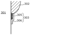
- FIG. 6 is a diagram showing an example of teeth in the oral cavity.
- teeth 301, gums 302, and plaque 303 are shown.
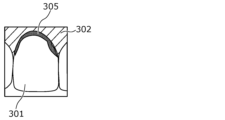
- FIG. 7 is a diagram showing an example of a layered model of the structure of region 304 shown in FIG. 6.
- plaque 303 is made up of layered layers of mature plaque (tartar) 305 and young plaque 306.
- the porphyrins in the plaque are excited, generating red fluorescence. Furthermore, the intensity of the fluorescence does not reflect the current bacterial flora, but is thought to indicate the accumulation of fluorescent substances (porphyrins). In other words, the more fluorescent substances are accumulated, the stronger the red fluorescence becomes. In other words, the level of porphyrin accumulation increases as the plaque matures. Therefore, the fluorescence intensity of mature plaque 305 is stronger than that of young plaque 306.
- the detection unit 102 detects the accumulation level (concentration or density) of the fluorescent substance by comparing the intensity of the red fluorescence per unit area of the plaque region. In other words, the detection unit 102 detects the amount of fluorescent substance contained in the plaque and tartar attached to the teeth per unit area.
- a plaque region is extracted from one or more fourth pixels from the HSV image that satisfy at least one of the following: saturation S within a first predetermined range, hue H within a second predetermined range, and brightness V within a third predetermined range.
- Equations 5, 6, and 7 hold true in the cylindrical model of HSV space.
- the second RGB image is an image after white balance adjustment processing
- MAX R
- MIN G or B. That is, in the plaque region, the brightness V is determined by the value of R, regardless of the saturation S and hue H.
- the fluorescent wavelength of porphyrin a fluorescent substance found in dental plaque
- the concentration of porphyrin accumulated in the plaque region can be evaluated by detecting the brightness V value of the HSV image of the plaque region.
- FIG. 8 is a diagram for explaining the illuminance of fluorescent light at depth D.
- the LED light and plaque fluorescence attenuate as they travel through the plaque. Attenuation of the LED light and plaque fluorescence outside the plaque (i.e. in the atmosphere) can be ignored.
- the brightness of the plaque fluorescence is proportional to the illuminance of the LED light that hits the plaque.
- Equation 8 the spectral transmittance T d ⁇ 1 is expressed by Equation 9, and therefore Equation 10 can be obtained from Equations 8 and 9.
- the luminance E ⁇ 2 of the fluorescence from the dental plaque at the depth D is expressed by Equation 11 using a proportionality constant k.
- Equation 12 the luminance E ⁇ 2 of the fluorescence emitted by plaque is constant regardless of location if the depth D is the same. It is assumed that the density of plaque is uniformly distributed, and the attenuation rate ⁇ ⁇ 2 of the fluorescence due to plaque is constant regardless of the depth D.
- Equation 12 the illuminance E ⁇ 2 (D) of the fluorescence observed from plaque at depth D is expressed by Equation 12.
- the spectral transmittance T d ⁇ 2 is expressed by Equation 13, so Equation 14 can be obtained from Equations 12 and 13.
- Equation 15 can be obtained from Equations 10, 11, and 14.
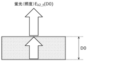
- E ⁇ 2_t (D0) is a diagram for explaining the illuminance E ⁇ 2_t (D0) of the fluorescence observed from the plaque having a thickness D0.
- the illuminance E ⁇ 2_t (D0) of the fluorescence observed from the plaque having a thickness D0 can be expressed as an integral value of E ⁇ 2 (D).
- E ⁇ 2_t (D0) is expressed by Equation 16.
- the red fluorescence intensity from a plaque layer (biofilm) of thickness D0 reflects the accumulation level of porphyrin in the plaque layer (biofilm).
- the porphyrin concentration in the plaque layer was assumed to be constant, but the fluorescence reaction can be explained when the lower layer in the biofilm model is tartar with a high porphyrin concentration and the upper layer is young plaque with a low porphyrin concentration. That is, as shown in Figure 7, when the lower layer of mature plaque 305 (tartar) is covered by the upper layer of young plaque 306, the red fluorescence in the area with the lower layer of mature plaque 305 is stronger than the red fluorescence in the area without the lower layer of mature plaque 305.
- the fluorescence changes depending on the thickness D (the greater the thickness D, the stronger the fluorescence).
- the intensity of the fluorescence indicates the accumulation level, which is proportional to the concentration and amount (thickness) of the fluorescent substance.
- FIG. 10 is a flowchart of the process of detecting the concentration distribution of fluorescent substances by the detection unit 102.
- the detection unit 102 detects the accumulation level for each pixel by performing the process shown in FIG. 10 for each pixel in the plaque region included in the HSV image.
- the detection unit 102 may also detect the accumulation level for each unit pixel by performing the process shown in FIG. 10 for each unit pixel made up of multiple pixels. In this case, for example, the average brightness value of the multiple pixels included in the unit pixel may be used.
- the detection unit 102 determines whether the brightness of the target pixel is less than the first threshold (S121). If the brightness of the target pixel is less than the first threshold (Yes in S121), the detection unit 102 determines that the accumulation level of the target pixel is accumulation level 0 (e.g., no plaque) (S122).
- the detection unit 102 determines that the accumulation level of the target pixel is accumulation level 1 (e.g., young plaque) (S124).
- accumulation level 1 e.g., young plaque
- the detection unit 102 determines that the accumulation level of the target pixel is accumulation level 2 (e.g., mature plaque (tartar)) (S125).
- accumulation level 2 e.g., mature plaque (tartar)
- the detection unit 102 detects the distribution of accumulation levels (concentration of fluorescent material) by determining the accumulation level for each pixel.
- the distribution of accumulation levels is information that indicates the accumulation level for each two-dimensional position (e.g., pixel) on the xy plane.
- the detection unit 102 then assigns the three accumulation levels 0 to 2 to different gradations, and generates, for example, a fourth RGB image by superimposing the distribution of accumulation levels displayed in gradations on the second RGB image.
- FIG. 11 is a diagram showing an example of a fourth RGB image. For example, as shown in FIG. 11, a pattern of a first gradation (e.g., 0.5) is superimposed on the area of young plaque 306, and a pattern of a second gradation (e.g., 1.0) is superimposed on the area of mature plaque 305.
- a first gradation e.g., 0.5
- a second gradation e.g., 1.0
- the accumulation levels may be four or more.
- the second image onto which the accumulation level distribution is superimposed may be something other than the second RGB image.
- the second image may be the first RGB image, or an image generated by performing image processing on the first RGB image or the second RGB image.
- FIG. 12 is a diagram showing an example of teeth after intraoral care has been performed on the teeth in the state shown in FIG. 11. As shown in FIG. 12, by performing intraoral care (tooth brushing, etc.), young plaque 306 is removed, but mature plaque 305 is not removed.
- intraoral care teeth brushing, etc.
- the detection unit 102 may determine an oral care score (whether there is any area left unbrushed) based on the state of the young plaque 306.
- the detection unit 102 may also recommend that the user have a checkup at a dentist based on the state of the mature plaque 305.
- the detection unit 102 calculates the ratio of the area of young plaque 306 to the area of the tooth region. That is, the detection unit 102 calculates (area of young plaque 306)/(area of tooth region) ⁇ 100 ⁇ % ⁇ as a first area ratio of young plaque 306.
- the detection unit 102 also calculates the ratio of the area of mature plaque 305 to the area of the tooth region. That is, the detection unit 102 calculates (area of mature plaque 305)/(area of tooth region) ⁇ 100 ⁇ % ⁇ as a second area ratio of mature plaque 305.
- the detection unit 102 may use the calculated first area ratio to determine an oral care score.
- the detection unit 102 may also use the calculated second area ratio to recommend that the user see a dentist. For example, when the second area ratio is greater than a predetermined threshold, the detection unit 102 may display a message to the user recommending that the user see a dentist.
- the calculation and determination of the area ratio may be performed collectively for all teeth in the oral cavity.
- the area ratio may be the ratio between the area of the total dental region of all teeth and the total area of plaque (young plaque 306 or mature plaque 305).
- the calculation and determination of the area ratio may be performed individually for each of multiple teeth in the oral cavity.
- the area ratio may be the ratio between the area of the dental region of one tooth and the area of plaque of one tooth.
- the calculation and determination of the area ratio may be performed individually for each of the dental regions into which multiple teeth in the oral cavity are divided.
- a dental region is, for example, a region that includes two or more teeth, such as the right back of the upper jaw or the left front of the lower jaw.
- the identification unit 104 shown in FIG. 5 also identifies the types of multiple teeth in the image data based on the image data.
- the type of tooth is information that can uniquely identify a tooth in the oral cavity, such as a maxillary right central incisor or a mandibular left lateral incisor.
- the identification unit 104 acquires reference data corresponding to multiple tooth types from the cloud server 80, and identifies the types of each of the multiple teeth included in the image data by comparing features, etc., using the image data and the acquired reference data.
- the identification unit 104 stores the concentration distribution (accumulation level) of the fluorescent material detected by the detection unit 102 in the memory unit 105 in association with multiple tooth types.
- the memory unit 105 stores the concentration distribution (accumulation level) of the fluorescent material for each tooth. Furthermore, the area ratio and judgment process for each tooth described above may be performed using this information for each tooth.
- the display unit 103 is a display device provided in the mobile terminal 70, and displays a fourth RGB image in which the distribution of accumulation levels is superimposed on the image data.
- the display unit 103 also displays the above-mentioned determination results and messages based on the determination results.
- the display unit 103 may also display the above-mentioned area ratio, etc.
- the detection unit 102 performs exposure control processing on the first RGB image and performs white balance adjustment processing on the third RGB image generated by the exposure control processing, but the present invention is not limited to this and the exposure control processing may not be performed. For example, if a first RGB image in which the occurrence of variations in the luminance distribution is reduced is obtained, the exposure control processing may not be performed. For example, the variation in the luminance distribution of the obtained first RGB image may be reduced by controlling the illumination so that the shooting conditions are constant.
- the accumulation level is detected using image data after image processing (exposure control processing, white balance adjustment processing, etc.), but some or all of the image processing may not be performed.
- image processing exposure control processing, white balance adjustment processing, etc.
- an HSV image may be generated from the first RGB image, and the accumulation level may be detected using the HSV image.
- the accumulation level is detected using the brightness of the HSV image, but the method of determining the accumulation level is not limited to this.
- the saturation or hue of the HSV image may be used, or a combination of the brightness and at least one of the saturation and hue may be used.
- an evaluation value calculated from the brightness and at least one of the saturation and hue may be compared with a threshold value.
- the accumulation level may be detected using an RGB image.
- the R value of the RGB image may be used, or a combination of the R value and at least one of the G value and B value may be used.
- an evaluation value calculated from the R value and at least one of the G value and B value may be compared with a threshold value.
- the intraoral camera 10 transmits the first RGB image to the mobile terminal 70, and the first RGB image is processed in the mobile terminal 70, but this is not limited thereto.
- the first RGB image may be transmitted to the cloud server 80, the cloud server 80 performs the above processing, and the second RGB image or the fourth RGB image as the processing result may be transmitted to the mobile terminal 70.
- the first RGB image may be transmitted from the intraoral camera 10 to the cloud server 80 without passing through the mobile terminal 70, or may be transmitted from the intraoral camera 10 to the cloud server 80 via the mobile terminal 70.
- the accumulation level is detected using an HSV image, but the method of determining the accumulation level is not limited to this.
- an HSL image may be used instead of an HSV image.
- the detection unit 102 generates an HSL image by converting the color space of the second RGB image into an HSL space. Then, the detection unit 102 identifies, as a plaque region, a specific pixel region in which one or more fifth pixels that satisfy at least one of the following conditions is located among the multiple fifth pixels in the HSL image: saturation within a fourth predetermined range, hue within a fifth predetermined range, and luminance within a sixth predetermined range.
- the detection unit 102 detects the fluorescent substance concentration distribution using the HSL image. Specifically, the detection unit 102 detects the fluorescent substance concentration distribution using the luminance L value of the HSL image.
- the HSL color space (also called the HLS color space) is a color space consisting of three components: H (hue), S (saturation), and L (luminance), and is obtained by nonlinear transformation of the RGB color space.
- H (hue) of the HSL image is calculated using formula 5 above.
- L (brightness) is calculated using formula 17 below.
- S (saturation) is calculated using formula 18 below when a cylindrical model is used, and is calculated using formula 19 below when a biconical model is used.
- FIG. 13 is a diagram showing the relationship between fluorescence intensity, MIN, and k.
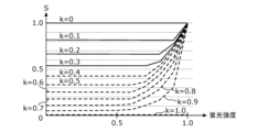
- FIG. 14 is a diagram showing the relationship between fluorescence intensity, S (saturation), and k.
- FIG. 15 is a diagram showing the relationship between fluorescence intensity, L (brightness), and k. Note that this example is an example when a cylindrical model is used.
- L changes linearly between 0 and 0.65, so the value of L is proportional to the amount of porphyrin. Therefore, the concentration distribution of the fluorescent substance (the amount of fluorescent substance contained in plaque and tartar attached to the teeth per unit area) can be detected based on the value of L.
- a blue light cut filter 20 is used as a method for generating a first RGB image in which at least a portion of the blue light region is attenuated from reflected light and fluorescence from the teeth, plaque, and tartar in the oral cavity that is irradiated with irradiation light of a predetermined wavelength that excites fluorescent substances contained in plaque and tartar.
- at least a portion of the blue light region may also be attenuated by signal processing without using the blue light cut filter 20.
- FIG. 16 is a diagram showing an example of pixel values in each image when the blue light region is attenuated by signal processing.
- the detection unit 102 generates a fifth RGB image by performing blue color cutting processing on the first RGB image, which is image data obtained by the image sensor 14, as shown in FIG. 16.
- the detection unit 102 may replace the blue pixel values with a predetermined value (for example, 0), or clip them to a predetermined value or less.
- the detection unit 102 generates a third RGB image by performing the above-mentioned exposure control process on the fifth RGB image thus generated. For example, the detection unit 102 multiplies R, G, and B by equal gains so that max(R, G, B) is a predetermined level.
- the detection unit 102 generates a second RGB image by performing the above-mentioned white balance adjustment process on the third RGB image. For example, the detection unit 102 multiplies R and B individually by a gain so that R and B are at the same level as G. Note that, when performing blue cut processing, the detection unit 102 does not need to multiply B by a gain in the white balance adjustment process. In addition, the above-mentioned fluorescent material concentration distribution detection process is performed using this second RGB image.
- an image (fifth RGB image) can be generated in which at least a portion of the blue light region is attenuated, just as in the case of using the blue light cutting filter 20.
- Figure 17 shows an example of pixel values in each image when the blue light region is attenuated by signal processing in this case.
- the detection unit 102 performs the same blue cut processing as described above on the second RGB image after the white balance adjustment processing to generate a sixth RGB image.
- the sixth RGB image is used to perform the above-mentioned fluorescent material concentration distribution detection processing.
- the second RGB image shown in Figure 16 is closer to the state where blue light has been cut using an optical filter, and the remaining R and G levels are also greater, resulting in a brighter image.
- the blue light cutting process may be digital or analog. Although the above describes an example in which the detection unit 102 (mobile terminal 70) performs the blue light cutting process, it may also be performed by the intraoral camera 10. In addition, in a typical image sensor used in an RGB camera, the output order of the R, G, and B pixel values is determined according to the RGB color filter array. Therefore, the B pixel value can be identified in the blue light cutting process.
- the detection unit 102 may extract a natural tooth region free of plaque from the first RGB image, and perform the white balance adjustment process using a plurality of pixels of the extracted natural tooth region.
- the first image processing may be a process of extracting a natural tooth region free of plaque and tartar from the first RGB image, and adjusting the gains of at least two color components of the red component, the green component, and the blue component of the first RGB image so that a first red pixel average value of a plurality of red pixel values of a plurality of first pixels constituting the natural tooth region, a first green pixel average value of a plurality of green pixel values of a plurality of first pixels, and a first blue pixel average value of a plurality of blue pixel values of a plurality of first pixels are equal to each other.
- the natural tooth region refers to the tooth region excluding the artificial tooth region.
- the artificial tooth is, for example, an artificial tooth or prosthesis made of metal (gold or silver, etc.), ceramic, zirconia, etc.
- the accuracy of the white balance adjustment process can be improved by performing the white balance adjustment process using pixel information of the natural tooth area excluding the artificial tooth area.
- the detection unit 102 detects a first natural tooth region in the first RGB image where the green pixel value (G) is equal to or greater than a first predetermined threshold value.
- excitation light blue light
- excitation fluorescence is emitted from the dentin. This excitation fluorescence passes through the enamel. This causes the natural tooth to fluoresce green.
- blue light is irradiated onto a filling in a caries treatment scar, it appears dark (low brightness) in the image captured by the camera, unlike when white light is irradiated.
- a natural tooth covered with enamel appears bright (high brightness) in the image. Therefore, by extracting areas where the green pixel value (G) is equal to or greater than a predetermined first threshold and extracting this green fluorescence, it is possible to identify the areas of natural teeth and exclude the areas of artificial teeth.
- a luminance value (Y) may be used instead of the green pixel value (G).
- the luminance value (Y) is calculated using the above formula 3. As shown in formula 3, the ratio of green pixel values to luminance values is high, so even when luminance values are used, detection can be performed in the same way as when green pixel values are used.
- the detection unit 102 may perform white balance adjustment processing using information on the first natural tooth area detected in this manner, or may detect a second natural tooth area by further excluding areas of plaque and tartar from the first natural tooth area, and perform white balance adjustment processing using information on the detected second natural tooth area.
- the detection unit 102 generates an HSV image from the first RGB image, and extracts areas where the H, S, and V values of the HSV image fall within a predetermined range as plaque or tartar areas.
- the detection unit 102 may also generate an HSL image from the first RGB image, and extract areas where the H, S, and L values of the HSL image fall within a predetermined range as plaque or tartar areas.
- the detection unit 102 detects the second natural tooth region by excluding the plaque or tartar region from the first natural tooth region.
- the plaque detection device (e.g., mobile terminal 70) according to this embodiment includes an acquisition unit 101 that acquires a first image (e.g., a first RGB image) in which at least a portion of the blue light region is attenuated from the reflected light and fluorescence from the teeth, plaque, and tartar in the oral cavity irradiated with irradiation light of a predetermined wavelength that excites the fluorescent substances contained in the plaque and tartar, and a detection unit 102 that detects the content per unit area of the fluorescent substances contained in the plaque and tartar attached to the teeth (e.g., the concentration distribution of the fluorescent substances) from the first image (e.g., based on the value of the fluorescence intensity of the fluorescent reaction of the fluorescent substances in the first image).
- a first image e.g., a first RGB image
- a detection unit 102 that detects the content per unit area of the fluorescent substances contained in the plaque and tartar attached to the teeth (e.g., the concentration distribution of the fluorescent substances) from
- the plaque detection device can detect the content per unit area of the fluorescent substances contained in the plaque and tartar attached to the teeth, and therefore can detect the condition of the teeth in detail. Furthermore, the plaque detection device can improve the detection accuracy of the amount of fluorescent substances contained in plaque and tartar attached to the teeth per unit area by using a first image in which at least a portion of the blue light region is attenuated from the reflected light and fluorescence from the teeth, plaque, and tartar in the oral cavity irradiated with irradiation light of a specific wavelength that excites the fluorescent substances contained in plaque and tartar.
- the detection unit 102 generates an HSV image from the first image, and detects the amount of fluorescent material contained in the plaque and tartar adhering to the teeth per unit area from the brightness value of the HSV image.
- the plaque detection device can accurately detect the amount of fluorescent material contained in the plaque and tartar adhering to the teeth per unit area based on the brightness value of the HSV image.
- the first image is a first RGB image
- the detection unit 102 generates a second RGB image by performing image processing including a first image processing on the first RGB image.
- the first image processing is a process of adjusting the gain of at least two color components of the red, green, and blue components of the RGB image to be processed so that a first red pixel average value of multiple red pixel values of multiple first pixels constituting a tooth region in the RGB image to be processed, a first green pixel average value of multiple green pixel values of the multiple first pixels, and a first blue pixel average value of multiple blue pixel values of the multiple first pixels are equal.
- the detection unit 102 generates an HSV image by converting the color space of the second RGB image into an HSV space.
- the plaque detection device can adjust the white balance of the first RGB image in which the fluorescently reacting teeth are captured. This allows the plaque detection device to generate a second RGB image that makes it easy to distinguish plaque regions, which are areas on the teeth where plaque is attached. This allows the plaque detection device to improve the detection accuracy of the amount of fluorescent substance contained in plaque and tartar attached to the teeth per unit area.
- the detection unit 102 identifies a specific pixel area in which one or more fourth pixels of the multiple fourth pixels in the HSV image are located, the saturation of which falls within a first predetermined range, the hue of which falls within a second predetermined range, and the brightness of which falls within at least one of a third predetermined range, and detects the amount of fluorescent substance contained in the plaque and tartar adhering to the teeth per unit area from the brightness value in the specific pixel area of the HSV image.
- the plaque detection device can improve the detection accuracy of the amount of fluorescent substance contained in the plaque and tartar adhering to the teeth per unit area by identifying the plaque area in the tooth image and then detecting the amount of fluorescent substance contained in the plaque and tartar adhering to the teeth.
- the detection unit 102 generates an HSL image from the first image, and detects the amount of fluorescent material contained in the plaque and tartar adhering to the teeth per unit area from the brightness value of the HSL image.
- the plaque detection device can accurately detect the amount of fluorescent material contained in the plaque and tartar adhering to the teeth per unit area based on the brightness value of the HSL image.
- the first image is a first RGB image
- the detection unit 102 generates a second RGB image by performing image processing including a first image processing on the first RGB image.
- the first image processing is a process of adjusting the gain of at least two color components of the red, green, and blue components of the RGB image to be processed so that a first red pixel average value of multiple red pixel values of multiple first pixels constituting a tooth region in the RGB image to be processed, a first green pixel average value of multiple green pixel values of the multiple first pixels, and a first blue pixel average value of multiple blue pixel values of the multiple first pixels are equal.
- the detection unit 102 generates an HSL image by converting the color space of the second RGB image into an HSL space.
- the plaque detection device can adjust the white balance of the first RGB image in which the fluorescently reacting teeth are captured. This allows the plaque detection device to generate a second RGB image that makes it easy to distinguish plaque regions, which are areas on the teeth where plaque is attached. This allows the plaque detection device to improve the detection accuracy of the amount of fluorescent substance contained in plaque and tartar attached to the teeth per unit area.
- the detection unit 102 identifies a specific pixel area in which one or more fifth pixels that are included in the HSL image and that have at least one of a fourth predetermined range for saturation, a fifth predetermined range for hue, and a sixth predetermined range for luminance are located, and detects the amount of fluorescent substance contained in plaque and tartar adhering to the teeth per unit area from the luminance value in the specific pixel area.
- the plaque detection device can improve the detection accuracy of the amount by detecting the amount of fluorescent substance contained in plaque and tartar adhering to the teeth per unit area after identifying the plaque area in the tooth image.
- the fluorescent substance is porphyrin.
- the detection unit 102 assigns the amount of fluorescent substance contained in the plaque and tartar attached to the teeth per unit area to three or more gradations, and generates a third image (for example, a fourth RGB image) in which the amount of fluorescent substance contained in the plaque and tartar attached to the teeth per unit area displayed in gradations is superimposed on a second image (for example, the first RGB image or the second RGB image) based on the first image.
- the generated third image can inform the user of the amount of fluorescent substance contained in the plaque and tartar attached to the teeth per unit area.
- the plaque detection device further includes an identification unit 104 that identifies the type of the photographed tooth, and a memory unit 105 that stores the amount of fluorescent substance contained in the plaque and tartar adhering to the tooth detected from the photographed tooth per unit area in association with the identified tooth type. This allows the plaque detection device to manage the amount of fluorescent substance contained in the plaque and tartar adhering to each tooth per unit area.
- the plaque detection device e.g., mobile terminal 70
- the plaque detection device is equipped with an acquisition unit 101 that acquires a first RGB image from reflected light and fluorescence from the teeth, plaque, and tartar in the oral cavity that is irradiated with irradiation light of a predetermined wavelength that excites fluorescent substances contained in the plaque and tartar, and a detection unit 102 that generates a second RGB image by performing image processing including a first image processing on the first RGB image, and detects the content per unit area of the fluorescent substances contained in the plaque and tartar attached to the teeth based on the fluorescence intensity value of the fluorescent reaction of the fluorescent substances in the second RGB image.
- an acquisition unit 101 that acquires a first RGB image from reflected light and fluorescence from the teeth, plaque, and tartar in the oral cavity that is irradiated with irradiation light of a predetermined wavelength that excites fluorescent substances contained in the plaque and tartar
- a detection unit 102 that generates a second RGB image by performing image processing including
- the first image processing is a process of extracting a natural tooth region free of plaque and tartar from the first RGB image, and adjusting the gain of at least two of the red, green, and blue color components of the first RGB image so that a first red pixel average value of the multiple red pixel values of the multiple first pixels constituting the natural tooth region, a first green pixel average value of the multiple green pixel values of the multiple first pixels, and a first blue pixel average value of the multiple blue pixel values of the multiple first pixels are equal.
- the plaque detection device can detect the amount of fluorescent substance contained in plaque and tartar attached to the teeth per unit area, and can therefore detect the condition of the teeth in detail. Furthermore, the plaque detection device can adjust the white balance of the first RGB image in which the fluorescently reacting teeth are photographed by performing the first image processing. Therefore, the plaque detection device can generate a second RGB image that makes it easy to distinguish the plaque region, which is the region on the tooth where plaque is attached. Therefore, the plaque detection device can improve the detection accuracy of the amount of fluorescent substance contained in plaque and tartar attached to the teeth per unit area. Furthermore, the plaque detection device can improve the accuracy of the white balance adjustment process by performing the first image processing using pixels of the natural tooth region where plaque and tartar are not attached.
- a first region e.g., a first natural tooth region
- a first region is detected that is (i) a region in the entire pixel region of the first RGB image where the luminance value is equal to or greater than a predetermined first threshold value, or (ii) a region in the entire pixel region of the first RGB image where the green pixel value is equal to or greater than a predetermined second threshold value, and the natural tooth region is extracted based on the first region.
- the plaque detection device can accurately detect the natural tooth region using the luminance value or the green pixel value.
- the region obtained by excluding the regions of plaque and tartar from the first region is extracted as the natural tooth region. This allows the plaque detection device to improve the accuracy of the white balance adjustment process.
- the first RGB image is an image in which at least a portion of the blue light region is attenuated from the reflected light and fluorescence from the teeth and plaque in the oral cavity.
- the plaque detection device can improve the detection accuracy of the content per unit area of fluorescent substances contained in plaque and tartar attached to the teeth by using the first image in which at least a portion of the blue light region is attenuated from the reflected light and fluorescence from the teeth, plaque, and tartar in the oral cavity that is irradiated with irradiation light of a specific wavelength that excites the fluorescent substances contained in the plaque and tartar.
- the detection unit 102 generates an HSV image from the second RGB image, and detects the amount of fluorescent material contained in the plaque and tartar adhering to the teeth per unit area from the brightness value of the HSV image.
- the plaque detection device can accurately detect the amount of fluorescent material contained in the plaque and tartar adhering to the teeth per unit area based on the brightness value of the HSV image.
- the detection unit 102 identifies a specific pixel area in which one or more fourth pixels of the multiple fourth pixels in the HSV image are located, the saturation of which falls within a first predetermined range, the hue of which falls within a second predetermined range, and the brightness of which falls within at least one of a third predetermined range, and detects the amount of fluorescent substance contained in the plaque and tartar adhering to the teeth per unit area from the brightness value in the specific pixel area.
- the plaque detection device can improve the detection accuracy of the amount by detecting the amount of fluorescent substance contained in the plaque and tartar adhering to the teeth per unit area after identifying the plaque area in the tooth image.
- the detection unit 102 generates an HSL image from the second RGB image, and detects the amount of fluorescent material contained in the plaque and tartar adhering to the teeth per unit area from the luminance value of the HSL image.
- the plaque detection device can accurately detect the amount of fluorescent material contained in the plaque and tartar adhering to the teeth per unit area based on the luminance value of the HSL image.
- the detection unit 102 identifies a specific pixel area in which one or more fifth pixels that are included in the HSL image and that have at least one of a fourth predetermined range for saturation, a fifth predetermined range for hue, and a sixth predetermined range for luminance are located, and detects the amount of fluorescent substance contained in plaque and tartar adhering to the teeth per unit area from the luminance value in the specific pixel area.
- the plaque detection device can improve the detection accuracy of the amount by detecting the amount of fluorescent substance contained in plaque and tartar adhering to the teeth per unit area after identifying the plaque area in the tooth image.
- the fluorescent substance is porphyrin.
- the detection unit 102 assigns the amount of fluorescent substance contained in the plaque and tartar attached to the teeth per unit area to three or more gradations, and generates a third image (for example, a fourth RGB image) in which the amount of fluorescent substance contained in the plaque and tartar attached to the teeth per unit area displayed in gradations is superimposed on a second image (for example, the first RGB image or the second RGB image) based on the first RGB image.
- the generated third image can inform the user of the amount of fluorescent substance contained in the plaque and tartar attached to the teeth per unit area.
- the plaque detection device further includes an identification unit 104 that identifies the type of the photographed tooth, and a memory unit 105 that stores the amount of fluorescent substance contained in the plaque and tartar adhering to the tooth detected from the photographed tooth per unit area in association with the identified tooth type. This allows the plaque detection device to manage the amount of fluorescent substance contained in the plaque and tartar adhering to each tooth per unit area.
- the intraoral camera system according to the embodiment of the present disclosure has been described above, but the present disclosure is not limited to this embodiment.
- the intraoral camera 10 is used primarily for photographing teeth, but the intraoral camera 10 may also be an oral care device equipped with a camera.
- the intraoral camera 10 may also be an oral irrigator equipped with a camera.
- each processing unit included in the intraoral camera system according to the above embodiment is typically realized as an LSI, which is an integrated circuit. These may be individually implemented as single chips, or may be integrated into a single chip that includes some or all of them.
- the integrated circuit is not limited to LSI, but may be realized by a dedicated circuit or a general-purpose processor. It is also possible to use an FPGA (Field Programmable Gate Array) that can be programmed after the LSI is manufactured, or a reconfigurable processor that can reconfigure the connections and settings of the circuit cells inside the LSI.
- FPGA Field Programmable Gate Array
- each component may be configured with dedicated hardware, or may be realized by executing a software program suitable for each component.
- Each component may be realized by a program execution unit such as a CPU or processor reading and executing a software program recorded on a recording medium such as a hard disk or semiconductor memory.
- the present disclosure may also be realized as an image display method executed by an intraoral camera system.
- the present disclosure may also be realized as an intraoral camera, a mobile terminal, or a cloud server included in an intraoral camera system.
- the division of functional blocks in the block diagram is one example, and multiple functional blocks may be realized as one functional block, one functional block may be divided into multiple blocks, or some functions may be transferred to other functional blocks. Furthermore, the functions of multiple functional blocks having similar functions may be processed in parallel or in a time-shared manner by a single piece of hardware or software.
- This disclosure can be applied to intraoral camera systems.
Landscapes
- Health & Medical Sciences (AREA)
- Life Sciences & Earth Sciences (AREA)
- Surgery (AREA)
- Engineering & Computer Science (AREA)
- Physics & Mathematics (AREA)
- General Health & Medical Sciences (AREA)
- Veterinary Medicine (AREA)
- Heart & Thoracic Surgery (AREA)
- Medical Informatics (AREA)
- Molecular Biology (AREA)
- Pathology (AREA)
- Animal Behavior & Ethology (AREA)
- Biophysics (AREA)
- Public Health (AREA)
- Biomedical Technology (AREA)
- Optics & Photonics (AREA)
- Nuclear Medicine, Radiotherapy & Molecular Imaging (AREA)
- Radiology & Medical Imaging (AREA)
- Dentistry (AREA)
- Oral & Maxillofacial Surgery (AREA)
- Signal Processing (AREA)
- Audiology, Speech & Language Pathology (AREA)
- Microelectronics & Electronic Packaging (AREA)
- Dental Tools And Instruments Or Auxiliary Dental Instruments (AREA)
Abstract
Description
図1は、本実施の形態に係る口腔内カメラシステムにおける口腔内カメラの斜視図である。図1に示すように、口腔内カメラ10は、片手で取り扱うことが可能な歯ブラシ状の筺体を備え、その筺体は、歯列撮影時にユーザの口腔内に配置されるヘッド部10aと、ユーザが把持するハンドル部10bと、ヘッド部10aとハンドル部10bとを接続するネック部10cとを含んでいる。
露出制御処理では、検出部102は、まず、第1RGB画像を構成する複数の第1RGB画素(第3画素)のうちで、RGBの値が下記の式1及び式2を満たす複数の画素を抽出する。
ホワイトバランス調整処理では、検出部102は、処理対象の第3RGB画像を構成する複数の第3RGB画素の内で、RGBの値が式1及び下記の式4を満たす複数の画素を抽出する。
検出部102は、HSV画像を用いて蛍光物質の濃度分布を検出する。具体的には、検出部102は、HSV画像の明度Vの値を用いて、蛍光物質の濃度分布を検出する。


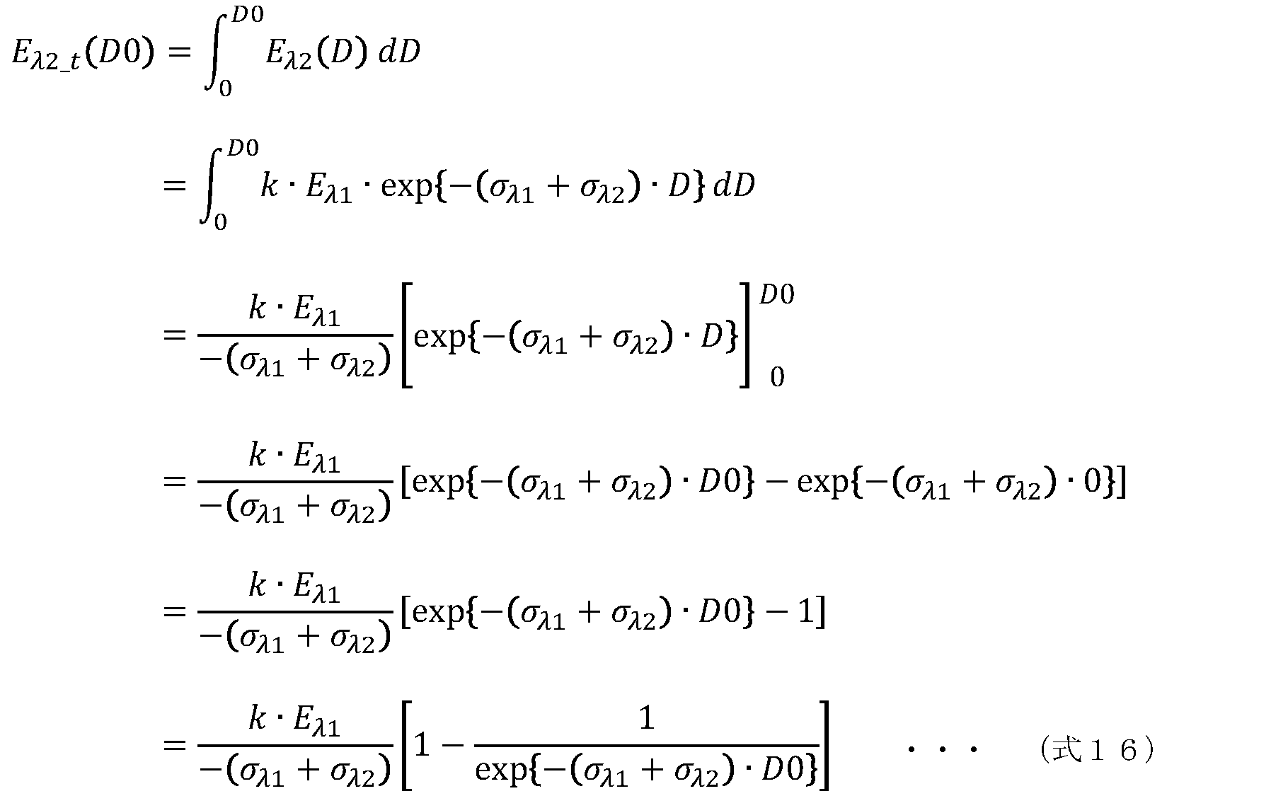
上記実施の形態では、検出部102は、第1RGB画像に対して露出制御処理を行い、露出制御処理で生成された第3RGB画像に対してホワイトバランス調整処理を行うとしたが、これに限らずに、露出制御処理を行わなくてもよい。例えば、輝度分布にバラツキが生じることを低減された第1RGB画像が得られていれば、露出制御処理は行われなくてもよい。例えば、撮影条件が一定になるように照明制御を行うことで、得られる第1RGB画像の輝度分布のバラツキを低減してもよい。
上記実施の形態では、画像処理(露出制御処理及びホワイトバランス調整処理等)が行われた後の画像データを用いて、蓄積レベルの検出が行われているが、画像処理の一部又は全てが行わなくてもよい。例えば、第1RGB画像からHSV画像が生成され、当該HSV画像を用いて蓄積レベルの検出が行われてもよい。
上記実施の形態では、HSV画像の明度を用いて、蓄積レベルの検出が行われているが、蓄積レベルの判定方法は、これに限らない。例えば、HSV画像の彩度又は色相が用いられてもよいし、明度と、彩度及び色相の少なくとも一方との組み合わせが用いられてもよい。例えば、明度と、彩度及び色相の少なくとも一方とから演算された評価値と閾値とが比較されてもよい。
上記実施の形態では、口腔内カメラ10は、携帯端末70に第1RGB画像を送信し、携帯端末70において第1RGB画像に対する処理が行われるとしたが、これに限らない。第1RGB画像は、クラウドサーバ80に送信され、クラウドサーバ80が上記処理を行い、処理結果の第2RGB画像または第4RGB画像を携帯端末70へ送信する構成であってもよい。この場合、第1RGB画像は、口腔内カメラ10から携帯端末70を経由せずにクラウドサーバ80へ送信されてもよいし、口腔内カメラ10から携帯端末70を経由してクラウドサーバ80へ送信されてもよい。
上記実施の形態では、HSV画像を用いて、蓄積レベルの検出が行われているが、蓄積レベルの判定方法は、これに限らない。例えば、HSV画像の代わりにHSL画像が用いられてもよい。

上記説明では、歯垢及び歯石に含まれる蛍光物質を励起する所定波長の照射光が照射されている口腔内の歯牙、歯垢及び歯石からの反射光及び蛍光から青色光領域の少なくとも一部を減衰した第1RGB画像を生成する方法として、青色光カットフィルタ20が用いられる例を示したが、青色光カットフィルタ20を用いずに信号処理により青色光領域の少なくとも一部を減衰してもよい。
検出部102は、ホワイトバランス調整処理(第1画像処理)において、第1RGB画像から歯垢が付着していない天然歯牙領域を抽出し、抽出した天然歯牙領域の複数の画素を用いてホワイトバランス調整処理を行ってもよい。つまり、第1画像処理は、第1RGB画像から歯垢及び歯石が付着していない天然歯牙領域を抽出し、天然歯牙領域を構成する複数の第1画素が有する複数の赤画素値の第1赤画素平均値と、複数の第1画素が有する複数の緑画素値の第1緑画素平均値と、複数の第1画素が有する複数の青画素値の第1青画素平均値とが等しくなるように、第1RGB画像の赤成分、緑成分、及び、青成分のうちの少なくとも2つの色成分のゲインを調整する処理であってもよい。
10a ヘッド部
10b ハンドル部
10c ネック部
12 撮影光学系
12a 入射口
14 撮像素子
16 レンズ
18 ミラー
20 青色光カットフィルタ
24 絞り
26A 第1のLED
26B 第2のLED
26C 第3のLED
26D 第4のLED
28 カバー
30 構図調節機構
32 焦点調節機構
34 筺体
36、40 アクチュエータ
38 レンズホルダ
50 中央制御部
54 LED制御部
56 レンズドライバ
58 無線通信モジュール
60 電源制御部
62 コントローラ
64 メモリ
66 電池
68 コイル
69 充電器
70 携帯端末
72 タッチスクリーン
80 クラウドサーバ
90 位置センサ
101 取得部
102 検出部
103 表示部
104 識別部
105 記憶部
301 歯牙
302 歯肉
303 歯垢
304 領域
305 熟成歯垢
306 若い歯垢
Claims (13)
- 歯垢及び歯石に含まれる蛍光物質を励起する所定波長の照射光が照射されている口腔内の歯牙、歯垢及び歯石からの反射光及び蛍光から第1RGB画像を取得する取得部と、
前記第1RGB画像に対して第1画像処理を含む画像処理を行うことで第2RGB画像を生成し、前記第2RGB画像における前記蛍光物質の蛍光反応の蛍光強度の値に基づき、前記歯牙に付着した前記歯垢及び前記歯石に含まれる蛍光物質の単位面積当たりの含有量を検出する検出部と、を備え、
前記第1画像処理は、前記第1RGB画像から歯垢及び歯石が付着していない天然歯牙領域を抽出し、前記天然歯牙領域を構成する複数の第1画素が有する複数の赤画素値の第1赤画素平均値と、前記複数の第1画素が有する複数の緑画素値の第1緑画素平均値と、前記複数の第1画素が有する複数の青画素値の第1青画素平均値とが等しくなるように、前記第1RGB画像の赤成分、緑成分、及び、青成分のうちの少なくとも2つの色成分のゲインを調整する処理である
歯垢検出装置。 - 前記天然歯牙領域の抽出では、
(i)前記第1RGB画像の全画素領域において、輝度値が予め定められた第1閾値以上の領域、又は、(ii)前記第1RGB画像の全画素領域において、緑画素値が予め定められた第2閾値以上の領域、である第1領域が検出され、前記第1領域に基づき前記天然歯牙領域が抽出される
請求項1記載の歯垢検出装置。 - 前記天然歯牙領域の抽出では、
前記第1領域から、歯垢及び歯石の領域を除外した領域が前記天然歯牙領域として抽出される
請求項2記載の歯垢検出装置。 - 前記第1RGB画像は、前記口腔内の前記歯牙及び前記歯垢からの反射光及び蛍光から青色光領域の少なくとも一部を減衰した画像である
請求項1~3のいずれか一項に記載の歯垢検出装置。 - 前記検出部は、前記第2RGB画像からHSV画像を生成し、前記HSV画像の明度の値から前記歯牙に付着した前記歯垢及び前記歯石に含まれる蛍光物質の前記単位面積当たりの含有量を検出する
請求項1~4のいずれか一項に記載の歯垢検出装置。 - 前記検出部は、
前記HSV画像が有する複数の第4画素のうち彩度が第1の所定範囲内、色相が第2の所定範囲内、及び、明度が第3の所定範囲内の少なくとも1つを満たす1以上の第4画素が位置する特定画素領域を特定し、
前記特定画素領域における前記明度の値から前記歯牙に付着した前記歯垢及び前記歯石に含まれる前記蛍光物質の前記単位面積当たりの含有量を検出する
請求項5記載の歯垢検出装置。 - 前記検出部は、前記第2RGB画像からHSL画像を生成し、前記HSL画像の輝度の値から前記歯牙に付着した前記歯垢及び前記歯石に含まれる蛍光物質の前記単位面積当たりの含有量を検出する
請求項1~4のいずれか一項に記載の歯垢検出装置。 - 前記検出部は、
前記HSL画像が有する複数の第5画素のうち彩度が第4の所定範囲内、色相が第5の所定範囲内、及び、輝度が第6の所定範囲内の少なくとも1つを満たす1以上の第5画素が位置する特定画素領域を特定し、
前記特定画素領域における前記輝度の値から前記歯牙に付着した前記歯垢及び前記歯石に含まれる前記蛍光物質の前記単位面積当たりの含有量を検出する
請求項7記載の歯垢検出装置。 - 前記蛍光物質はポルフィリンである
請求項1~8のいずれか一項に記載の歯垢検出装置。 - 前記検出部は、
前記歯牙に付着した前記歯垢及び前記歯石に含まれる前記蛍光物質の前記単位面積当たりの含有量を3以上の階調に割り付け、
前記第1RGB画像に基づく第2画像に、階調表示した前記歯牙に付着した前記歯垢及び前記歯石に含まれる前記蛍光物質の前記単位面積当たりの含有量を重ねた第3画像を生成する
請求項1~9のいずれか一項に記載の歯垢検出装置。 - 前記歯垢検出装置は、さらに、
撮影された歯牙の種類を識別する識別部と、
前記撮影された歯牙から検出した歯牙に付着した歯垢及び歯石に含まれる蛍光物質の単位面積当たりの含有量を、識別された前記歯牙の種類と対応付けて記憶する記憶部と、を備える
請求項1~10のいずれか一項に記載の歯垢検出装置。 - 歯垢及び歯石に含まれる蛍光物質を励起する所定波長の照射光が照射されている口腔内の歯牙、歯垢及び歯石からの反射光及び蛍光から第1RGB画像を取得し、
前記第1RGB画像に対して第1画像処理を含む画像処理を行うことで第2RGB画像を生成し、前記第2RGB画像における前記蛍光物質の蛍光反応の蛍光強度の値に基づき、前記歯牙に付着した前記歯垢及び前記歯石に含まれる蛍光物質の単位面積当たりの含有量を検出し、
前記第1画像処理は、前記第1RGB画像から歯垢及び歯石が付着していない天然歯牙領域を抽出し、前記天然歯牙領域を構成する複数の第1画素が有する複数の赤画素値の第1赤画素平均値と、前記複数の第1画素が有する複数の緑画素値の第1緑画素平均値と、前記複数の第1画素が有する複数の青画素値の第1青画素平均値とが等しくなるように、前記第1RGB画像の赤成分、緑成分、及び、青成分のうちの少なくとも2つの色成分のゲインを調整する処理である
歯垢検出方法。 - 請求項12記載の歯垢検出方法をコンピュータに実行させるためのプログラム。
Priority Applications (3)
| Application Number | Priority Date | Filing Date | Title |
|---|---|---|---|
| EP24819288.2A EP4725390A1 (en) | 2023-06-08 | 2024-06-03 | Dental plaque detection device, dental plaque detection method, and program |
| CN202480003912.6A CN119947632A (zh) | 2023-06-08 | 2024-06-03 | 牙垢检测装置、牙垢检测方法及程序 |
| JP2025526099A JP7784630B2 (ja) | 2023-06-08 | 2024-06-03 | 歯垢検出装置、歯垢検出方法及びプログラム |
Applications Claiming Priority (2)
| Application Number | Priority Date | Filing Date | Title |
|---|---|---|---|
| JP2023-094470 | 2023-06-08 | ||
| JP2023094470 | 2023-06-08 |
Publications (1)
| Publication Number | Publication Date |
|---|---|
| WO2024253058A1 true WO2024253058A1 (ja) | 2024-12-12 |
Family
ID=93795964
Family Applications (2)
| Application Number | Title | Priority Date | Filing Date |
|---|---|---|---|
| PCT/JP2024/020178 Ceased WO2024253057A1 (ja) | 2023-06-08 | 2024-06-03 | 歯垢検出装置、歯垢検出方法及びプログラム |
| PCT/JP2024/020180 Ceased WO2024253058A1 (ja) | 2023-06-08 | 2024-06-03 | 歯垢検出装置、歯垢検出方法及びプログラム |
Family Applications Before (1)
| Application Number | Title | Priority Date | Filing Date |
|---|---|---|---|
| PCT/JP2024/020178 Ceased WO2024253057A1 (ja) | 2023-06-08 | 2024-06-03 | 歯垢検出装置、歯垢検出方法及びプログラム |
Country Status (4)
| Country | Link |
|---|---|
| EP (2) | EP4725389A1 (ja) |
| JP (2) | JP7784629B2 (ja) |
| CN (2) | CN119947632A (ja) |
| WO (2) | WO2024253057A1 (ja) |
Families Citing this family (1)
| Publication number | Priority date | Publication date | Assignee | Title |
|---|---|---|---|---|
| CN120598940B (zh) * | 2025-08-05 | 2025-10-17 | 陕西省第二人民医院(陕西省老年病医院) | 一种口腔牙菌斑标记检测方法及系统 |
Citations (4)
| Publication number | Priority date | Publication date | Assignee | Title |
|---|---|---|---|---|
| JP2013248220A (ja) | 2012-06-01 | 2013-12-12 | Sony Corp | 歯用装置、画像取得方法及び情報処理装置 |
| JP2014004329A (ja) * | 2012-06-01 | 2014-01-16 | Sony Corp | 歯用装置、医療用装置及び算出方法 |
| JP2014133029A (ja) * | 2013-01-11 | 2014-07-24 | Panasonic Corp | 歯垢検知システム及び歯垢検知方法 |
| WO2016140199A1 (ja) * | 2015-03-02 | 2016-09-09 | シチズンホールディングス株式会社 | 光測定装置及びこれを備えた歯ブラシ |
-
2024
- 2024-06-03 JP JP2025526098A patent/JP7784629B2/ja active Active
- 2024-06-03 CN CN202480003912.6A patent/CN119947632A/zh active Pending
- 2024-06-03 JP JP2025526099A patent/JP7784630B2/ja active Active
- 2024-06-03 CN CN202480003754.4A patent/CN119768102A/zh active Pending
- 2024-06-03 WO PCT/JP2024/020178 patent/WO2024253057A1/ja not_active Ceased
- 2024-06-03 WO PCT/JP2024/020180 patent/WO2024253058A1/ja not_active Ceased
- 2024-06-03 EP EP24819287.4A patent/EP4725389A1/en active Pending
- 2024-06-03 EP EP24819288.2A patent/EP4725390A1/en active Pending
Patent Citations (4)
| Publication number | Priority date | Publication date | Assignee | Title |
|---|---|---|---|---|
| JP2013248220A (ja) | 2012-06-01 | 2013-12-12 | Sony Corp | 歯用装置、画像取得方法及び情報処理装置 |
| JP2014004329A (ja) * | 2012-06-01 | 2014-01-16 | Sony Corp | 歯用装置、医療用装置及び算出方法 |
| JP2014133029A (ja) * | 2013-01-11 | 2014-07-24 | Panasonic Corp | 歯垢検知システム及び歯垢検知方法 |
| WO2016140199A1 (ja) * | 2015-03-02 | 2016-09-09 | シチズンホールディングス株式会社 | 光測定装置及びこれを備えた歯ブラシ |
Also Published As
| Publication number | Publication date |
|---|---|
| JPWO2024253058A1 (ja) | 2024-12-12 |
| EP4725389A1 (en) | 2026-04-15 |
| JPWO2024253057A1 (ja) | 2024-12-12 |
| JP7784630B2 (ja) | 2025-12-12 |
| JP7784629B2 (ja) | 2025-12-12 |
| CN119947632A (zh) | 2025-05-06 |
| CN119768102A (zh) | 2025-04-04 |
| WO2024253057A1 (ja) | 2024-12-12 |
| EP4725390A1 (en) | 2026-04-15 |
Similar Documents
| Publication | Publication Date | Title |
|---|---|---|
| JP4527166B2 (ja) | 双方向歯科治療ネットワーク | |
| WO2024106391A1 (ja) | 画像処理方法、画像処理装置、及び、プログラム | |
| CN102327156A (zh) | 牙齿色度映射 | |
| JP2002529122A (ja) | 歯のシェードを解析するシステムならびに方法 | |
| US10876972B2 (en) | Full scale Raman imaging for early caries detection | |
| KR20230153430A (ko) | 치과용 영상 시스템 및 이미지 분석 | |
| JP7784630B2 (ja) | 歯垢検出装置、歯垢検出方法及びプログラム | |
| CN101331519A (zh) | 图像组合装置 | |
| Moussa | Dental Shade Matching: Recent technologies and future smart applications | |
| JP6319980B2 (ja) | 歯牙測色方法、歯牙測色装置、及び歯牙測色プログラム | |
| WO2023163051A1 (ja) | 口腔洗浄装置、制御装置、口腔洗浄方法、及び、プログラム | |
| EP4254936B1 (en) | Dentition image capturing system and dentition image capturing method | |
| JP6030651B2 (ja) | 歯科用シェード合わせのための適応型照明方法および装置 | |
| EP3459494B1 (en) | Dental health assessment assisting system | |
| WO2025079525A1 (ja) | 画像処理方法、画像処理装置及びプログラム | |
| JP2009195495A (ja) | 歯科用測色装置 | |
| WO2025182844A1 (ja) | 画像処理方法、画像処理装置、及び、プログラム | |
| JP7675374B2 (ja) | 口腔内カメラ、照明制御装置及び照明制御方法 | |
| CN122003202A (zh) | 图像处理方法、图像处理装置以及程序 | |
| WO2025173550A1 (ja) | 情報処理装置、情報処理方法及びプログラム | |
| WO2025173551A1 (ja) | 情報処理装置、情報処理方法及びプログラム | |
| WO2025197670A1 (ja) | 歯周疾患検出システム、歯周疾患検出方法及びプログラム | |
| WO2025115505A1 (ja) | 歯列画像生成装置、歯列画像生成方法及びプログラム | |
| WO2025115504A1 (ja) | 歯列画像生成装置、歯列画像生成方法及びプログラム | |
| WO2025197661A1 (ja) | 歯周疾患検出システム、歯周疾患検出方法及びプログラム |
Legal Events
| Date | Code | Title | Description |
|---|---|---|---|
| 121 | Ep: the epo has been informed by wipo that ep was designated in this application |
Ref document number: 24819288 Country of ref document: EP Kind code of ref document: A1 |
|
| WWE | Wipo information: entry into national phase |
Ref document number: 2025526099 Country of ref document: JP |
|
| WWE | Wipo information: entry into national phase |
Ref document number: 202480003912.6 Country of ref document: CN |
|
| WWP | Wipo information: published in national office |
Ref document number: 202480003912.6 Country of ref document: CN |
|
| WWE | Wipo information: entry into national phase |
Ref document number: 2024819288 Country of ref document: EP |
|
| NENP | Non-entry into the national phase |
Ref country code: DE |
|
| ENP | Entry into the national phase |
Ref document number: 2024819288 Country of ref document: EP Effective date: 20260108 |
|
| ENP | Entry into the national phase |
Ref document number: 2024819288 Country of ref document: EP Effective date: 20260108 |
|
| ENP | Entry into the national phase |
Ref document number: 2024819288 Country of ref document: EP Effective date: 20260108 |
|
| ENP | Entry into the national phase |
Ref document number: 2024819288 Country of ref document: EP Effective date: 20260108 |
|
| ENP | Entry into the national phase |
Ref document number: 2024819288 Country of ref document: EP Effective date: 20260108 |