WO2024253075A1 - All-solid-state battery and method for manufacturing same - Google Patents
All-solid-state battery and method for manufacturing same Download PDFInfo
- Publication number
- WO2024253075A1 WO2024253075A1 PCT/JP2024/020301 JP2024020301W WO2024253075A1 WO 2024253075 A1 WO2024253075 A1 WO 2024253075A1 JP 2024020301 W JP2024020301 W JP 2024020301W WO 2024253075 A1 WO2024253075 A1 WO 2024253075A1
- Authority
- WO
- WIPO (PCT)
- Prior art keywords
- solid electrolyte
- positive electrode
- negative electrode
- electrolyte layer
- solid
- Prior art date
- Legal status (The legal status is an assumption and is not a legal conclusion. Google has not performed a legal analysis and makes no representation as to the accuracy of the status listed.)
- Ceased
Links
Images
Classifications
-
- Y—GENERAL TAGGING OF NEW TECHNOLOGICAL DEVELOPMENTS; GENERAL TAGGING OF CROSS-SECTIONAL TECHNOLOGIES SPANNING OVER SEVERAL SECTIONS OF THE IPC; TECHNICAL SUBJECTS COVERED BY FORMER USPC CROSS-REFERENCE ART COLLECTIONS [XRACs] AND DIGESTS
- Y02—TECHNOLOGIES OR APPLICATIONS FOR MITIGATION OR ADAPTATION AGAINST CLIMATE CHANGE
- Y02E—REDUCTION OF GREENHOUSE GAS [GHG] EMISSIONS, RELATED TO ENERGY GENERATION, TRANSMISSION OR DISTRIBUTION
- Y02E60/00—Enabling technologies; Technologies with a potential or indirect contribution to GHG emissions mitigation
- Y02E60/10—Energy storage using batteries
-
- Y—GENERAL TAGGING OF NEW TECHNOLOGICAL DEVELOPMENTS; GENERAL TAGGING OF CROSS-SECTIONAL TECHNOLOGIES SPANNING OVER SEVERAL SECTIONS OF THE IPC; TECHNICAL SUBJECTS COVERED BY FORMER USPC CROSS-REFERENCE ART COLLECTIONS [XRACs] AND DIGESTS
- Y02—TECHNOLOGIES OR APPLICATIONS FOR MITIGATION OR ADAPTATION AGAINST CLIMATE CHANGE
- Y02P—CLIMATE CHANGE MITIGATION TECHNOLOGIES IN THE PRODUCTION OR PROCESSING OF GOODS
- Y02P70/00—Climate change mitigation technologies in the production process for final industrial or consumer products
- Y02P70/50—Manufacturing or production processes characterised by the final manufactured product
Definitions
- the present invention relates to a highly reliable all-solid-state battery and a manufacturing method.
- lithium batteries particularly lithium ion batteries, that can meet this demand use lithium-containing composite oxides such as lithium cobalt oxide ( LiCoO2 ) and lithium nickel oxide ( LiNiO2 ) as the positive electrode active material, graphite or the like as the negative electrode active material, and an organic electrolyte solution containing an organic solvent and a lithium salt as the non-aqueous electrolyte.
- lithium-containing composite oxides such as lithium cobalt oxide ( LiCoO2 ) and lithium nickel oxide ( LiNiO2 ) as the positive electrode active material, graphite or the like as the negative electrode active material, and an organic electrolyte solution containing an organic solvent and a lithium salt as the non-aqueous electrolyte.
- lithium-ion batteries As devices that use lithium-ion batteries continue to develop, there is a demand for longer life, higher capacity, and higher energy density lithium-ion batteries, as well as a high demand for the reliability of these longer life, higher capacity, and higher energy density lithium-ion batteries.
- the organic electrolyte used in lithium-ion batteries contains organic solvents, which are flammable substances, and so there is a possibility that the organic electrolyte may generate abnormal heat if an abnormality such as a short circuit occurs in the battery. Furthermore, with the recent trend toward higher energy density in lithium-ion batteries and an increasing amount of organic solvent in the organic electrolyte, there is a demand for even greater reliability in lithium-ion batteries.
- all-solid-state lithium batteries (all-solid-state batteries) that do not use organic solvents are also being considered.
- All-solid-state lithium batteries use a molded solid electrolyte that does not use organic solvents instead of the conventional organic solvent-based electrolyte, and are highly reliable with no risk of abnormal heat generation from the solid electrolyte. For this reason, there are high expectations for them, especially in product areas that require high-capacity secondary batteries.
- Solid-state batteries are also highly reliable and environmentally resistant, and have a long lifespan, making them promising maintenance-free batteries that can contribute to social development while also continuing to contribute to safety and security.
- Providing solid-state batteries to society can contribute to the achievement of Goal 3 (Ensure healthy lives and promote well-being for all at all ages), Goal 7 (Ensure access to affordable, reliable, sustainable and modern energy for all), Goal 11 (Make cities and human settlements inclusive, safe, resilient and sustainable), and Goal 12 (Ensure sustainable consumption and production patterns) out of the 17 Sustainable Development Goals (SDGs) established by the United Nations.
- SDGs Sustainable Development Goals
- Patent Document 1 proposes a secondary battery structure in which an insulating layer interposed between a positive electrode layer and a negative electrode layer is composed of an electrolyte layer and a polymer-rich layer that has more polymer than the electrolyte layer, and the electrolyte layer is disposed on the positive electrode layer and negative electrode layer side, in order to solve problems such as short circuits caused by the appearance of adhesion in secondary batteries that have electrolytes with low fluidity such as solid electrolytes.
- Patent Documents 2 to 5 propose filling the voids in a porous substrate such as a nonwoven fabric with a solid electrolyte to produce a solid electrolyte sheet that combines lithium ion conductivity and strength, and using this solid electrolyte sheet to construct an all-solid-state secondary battery.
- Patent Document 5 shows that by making the thickness of the porous substrate 70% or more of the overall thickness of the solid electrolyte sheet, the mechanical strength of the solid electrolyte sheet can be improved, and even if the area of the solid electrolyte sheet is increased, damage to the solid electrolyte and falling off of the solid electrolyte from the porous substrate can be prevented.
- Patent Document 5 makes it possible, for example, to enlarge the size of an all-solid-state battery, thereby achieving a high capacity.
- a positive electrode having a positive electrode mixture layer containing a positive electrode active material or a negative electrode having a negative electrode mixture layer containing a negative electrode active material is integrated with a solid electrolyte sheet having a porous substrate, for example, by pressure molding, cracks may occur in the solid electrolyte sheet, causing a short circuit in the battery, or the solid electrolyte sheet may peel off from the positive electrode or negative electrode due to insufficient bonding between the solid electrolyte sheet and the positive electrode or negative electrode. Therefore, in all-solid-state batteries having a solid electrolyte sheet as a solid electrolyte layer, there is a need to develop technology that suppresses the occurrence of such problems and increases reliability.
- the present invention was made in consideration of the above circumstances, and its purpose is to provide a highly reliable all-solid-state battery and a method for manufacturing the same.
- the all-solid-state battery of the present invention has an electrode body in which a positive electrode and a negative electrode are laminated with a solid electrolyte layer interposed therebetween, and the solid electrolyte layer has a porous substrate and is characterized in that it is a laminate of a solid electrolyte layer (I) having a portion protruding from the ends of the positive electrode and the negative electrode in a planar view, a solid electrolyte layer (II) joined to the positive electrode and having a smaller area in a planar view than the solid electrolyte layer (I), and a solid electrolyte layer (III) joined to the negative electrode and having a smaller area in a planar view than the solid electrolyte layer (I).
- a solid electrolyte layer (I) having a portion protruding from the ends of the positive electrode and the negative electrode in a planar view
- a solid electrolyte layer (II) joined to the positive electrode and having a smaller area in a planar
- the manufacturing method of the all-solid-state battery of the present invention is a method for manufacturing an all-solid-state battery having an electrode body in which a positive electrode and a negative electrode are stacked with a solid electrolyte layer interposed therebetween, and the solid electrolyte layer is a laminate of a solid electrolyte layer (I) having a porous substrate, a solid electrolyte layer (II) bonded to the positive electrode, and a solid electrolyte layer (III) bonded to the negative electrode, and the manufacturing method includes the steps of: preparing a solid electrolyte sheet having a porous substrate and a solid electrolyte held by the porous substrate; preparing a positive electrode coated on one side with a solid electrolyte; preparing a negative electrode coated on one side with a solid electrolyte; attaching the positive electrode to one side of the solid electrolyte sheet so that the solid electrolyte covering the positive electrode is in contact with the one side of the solid electrolyte sheet; and attaching
- the present invention provides a highly reliable all-solid-state battery and a method for manufacturing the same.
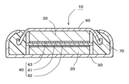
- FIG. 1 is a cross-sectional view illustrating a schematic diagram of an example of an all-solid-state battery of the present invention.
- the all-solid-state battery of the present invention has an electrode body in which a positive electrode and a negative electrode are stacked with a solid electrolyte layer interposed therebetween.
- the solid electrolyte layer has the following solid electrolyte layer (I), solid electrolyte layer (II), and solid electrolyte layer (III), and is configured by stacking these three layers.
- the solid electrolyte layer (I) has a porous substrate and has portions that protrude from the ends of the positive electrode and the negative electrode in a planar view.
- the solid electrolyte layer (II) is joined to the positive electrode and has a smaller area in a planar view than the solid electrolyte layer (I).
- the solid electrolyte layer (III) is joined to the negative electrode and has a smaller area in a planar view than the solid electrolyte layer (I).
- FIG. 1 shows a cross-sectional view that shows a schematic example of an all-solid-state battery of the present invention.
- the all-solid-state battery 10 shown in FIG. 1 has a positive electrode 20, a negative electrode 30, and a solid electrolyte layer 40 that is interposed between the positive electrode 20 and the negative electrode 30, enclosed within an exterior body formed of an exterior can 50, a sealing can 60, and a resin gasket 70 that is interposed between them.
- the sealing can 60 fits into the opening of the exterior can 50 via a gasket 70, and the open end of the exterior can 50 is tightened inward, causing the gasket 70 to come into contact with the sealing can 60, sealing the opening of the exterior can 50 and creating an airtight structure inside the battery.
- the outer can and the sealing can can be made of stainless steel or the like.
- the gasket can be made of polypropylene, nylon, or other materials. If heat resistance is required for the battery's intended use, heat-resistant resins with melting points exceeding 240°C, such as fluororesins such as tetrafluoroethylene-perfluoroalkoxyethylene copolymer (PFA), polyphenylene ether (PPE), polysulfone (PSF), polyarylate (PAR), polyethersulfone (PES), polyphenylene sulfide (PPS), and polyetheretherketone (PEEK), can also be used. If the battery is used in an application that requires heat resistance, a glass hermetic seal can be used for the sealing.
- PFA tetrafluoroethylene-perfluoroalkoxyethylene copolymer
- PPE polyphenylene ether
- PSF polysulfone
- PAR polyarylate
- PES polyethersulfone
- PPS
- the solid electrolyte layer 40 has a solid electrolyte layer (I) 41 having a porous substrate, a solid electrolyte layer (II) 42 joined to the positive electrode 20, and a solid electrolyte layer (III) 43 joined to the negative electrode 30.
- the solid electrolyte sheet when forming an electrode body using a solid electrolyte sheet having a porous substrate, if the solid electrolyte sheet is bonded to the positive and negative electrodes by pressure molding, the bonding between the positive electrode (positive electrode mixture compact containing positive electrode active material or positive electrode mixture layer) and the negative electrode (negative electrode mixture compact containing negative electrode active material or negative electrode mixture layer) may be insufficient, or cracks may occur in the solid electrolyte sheet.
- the solid electrolyte layer of the electrode body has a configuration having a solid electrolyte layer (I) containing a porous substrate and a solid electrolyte layer (II) and a solid electrolyte layer (III) arranged on both sides of the solid electrolyte layer (I), for example, a positive electrode having a solid electrolyte coating layer formed in advance on the solid electrolyte layer (I) side surface of the positive electrode mixture compact (positive electrode mixture layer) and a negative electrode having a solid electrolyte coating layer formed in advance on the solid electrolyte layer (I) side surface of the negative electrode mixture compact (negative electrode mixture layer) can be used, and the electrode body can be formed by pressing these coating layers on the solid electrolyte layer (I) side.
- the solid electrolyte layer (II) and the solid electrolyte layer (III) are well bonded to the solid electrolyte layer (I), and excessive pressure on the solid electrolyte layer (I) (solid electrolyte sheet) can be avoided when applying pressure to form the electrode body.
- the solid electrolyte layer of the all-solid-state battery is preferably such that the outer periphery of the solid electrolyte layer (I) protrudes from the ends of the positive and negative electrodes in a plan view of the electrode body (when viewed from above or below in FIG. 1), and the solid electrolyte layer (II) and the solid electrolyte layer (III) have a smaller area than the solid electrolyte layer (I) in a plan view.
- the solid electrolyte layer (II) can be made to have an area equivalent to that of the positive electrode mixture compact (positive electrode mixture layer) of the positive electrode, and the solid electrolyte layer (III) can be made to have an area equivalent to that of the negative electrode mixture compact (negative electrode mixture layer) of the negative electrode. That is, the size of the solid electrolyte layer (II) can be made the same as that of the positive electrode (positive electrode mixture layer), and the size of the solid electrolyte layer (III) can be made the same as that of the negative electrode (negative electrode mixture layer).
- the positive electrode mixture compact (positive electrode mixture layer) and the solid electrolyte layer (II), and the negative electrode mixture compact (negative electrode mixture layer) and the solid electrolyte layer (III) can be formed using a common mold (such as a metal mold), while the large-area solid electrolyte layer (I) can effectively prevent contact between the positive electrode and the negative electrode even if they are misaligned during assembly. Therefore, this action also makes it possible for the all-solid-state battery of the present invention to improve productivity and reliability.
- the outer periphery of the solid electrolyte layer (I) protrudes from the ends of the positive electrode and the negative electrode over the entire circumference. In other words, it is preferable that the parts of the solid electrolyte layer (I) that protrude from the ends of the positive electrode and the negative electrode are formed in a ring shape.
- the all-solid-state battery of the present invention includes primary batteries and secondary batteries.
- Solid electrolyte layer (I) has a porous substrate, and at least a portion of the solid electrolyte constituting the solid electrolyte layer (I) is present in a state of being held inside the porous substrate.
- the solid electrolyte layer (I) can be formed by using a solid electrolyte sheet obtained by filling the inside of a porous substrate with a solid electrolyte.
- the porous substrate of the solid electrolyte sheet may be made of a fibrous material, such as woven fabric, nonwoven fabric, or mesh, with nonwoven fabric being the most preferred.
- the fiber diameter of the fibrous material that constitutes the porous substrate is preferably 5 ⁇ m or less, and preferably 0.5 ⁇ m or more.
- the material of the fibrous material is not particularly limited as long as it does not react with metallic lithium and has insulating properties.
- resins such as polyolefins such as polypropylene and polyethylene; polystyrene; aramid; polyamide-imide; polyimide; nylon; polyesters such as polyethylene terephthalate (PET); polyarylate; cellulose and modified cellulose; etc.
- Inorganic materials such as glass, alumina, silica, and zirconia may also be used.
- a preferred material is polyarylate.
- the fibrous material may be made of one or more of the materials listed above.
- the porous substrate may be made of only fibrous materials of the same material, or may be made of a combination of two or more fibrous materials of different materials.
- the basis weight of the porous substrate is preferably 10 g/m2 or less, and more preferably 8 g/ m2 or less , so as to hold a sufficient amount of solid electrolyte to ensure good lithium ion conductivity and good lithium dendrite growth inhibition function, and from the viewpoint of ensuring sufficient strength, is preferably 3 g/m2 or more, and more preferably 4 g/ m2 or more .
- the solid electrolyte contained in the solid electrolyte sheet is not particularly limited as long as it has lithium ion conductivity.
- sulfide-based solid electrolytes, hydride-based solid electrolytes, halide-based solid electrolytes, oxide-based solid electrolytes, etc. can be used.
- Examples of sulfide-based solid electrolytes include particles of Li 2 S-P 2 S 5 , Li 2 S-SiS 2 , Li 2 S- P 2 S 5 -GeS 2 , and Li 2 S -B 2 S 3 based glass.
- thio- LISICON type electrolytes which have been attracting attention in recent years for their high lithium ion conductivity , are also available .
- M 2 is P or V
- M 3 is Al
- M 4 is Zn
- M 5 is S or either S and O
- X is F, Cl, Br or I, 0 ⁇ a ⁇ 3, 0 ⁇ b+c+d ⁇ 3, 0 ⁇ e ⁇ 3]
- Examples of hydride-based solid electrolytes include LiBH 4 , solid solutions of LiBH 4 and the following alkali metal compounds (for example, those in which the molar ratio of LiBH 4 to the alkali metal compound is 1:1 to 20:1), etc.
- Examples of the alkali metal compounds in the solid solutions include at least one selected from the group consisting of lithium halides (LiI, LiBr, LiF, LiCl, etc.), rubidium halides (RbI, RbBr, RbF, RbCl, etc.), cesium halides (CsI, CsBr, CsF, CsCl, etc.), lithium amide, rubidium amide, and cesium amide.
- lithium halides LiI, LiBr, LiF, LiCl, etc.
- rubidium halides RbI, RbBr, RbF, RbCl, etc.
- cesium halides CsI, CsBr, CsF, Cs
- Other known solid electrolytes that can be used include those described in, for example, WO 2020/070958 and WO 2020/070955.
- oxide-based solid electrolytes examples include garnet-type Li 7 La 3 Zr 2 O 12 , NASICON-type Li 1+O Al 1+O Ti 2-O (PO 4 ) 3 and Li 1+p Al 1+p Ge 2-p (PO 4 ) 3 , and perovskite-type Li 3q La 2/3-q TiO 3 .
- solid electrolyte only one of the above-mentioned examples may be used, or two or more may be used in combination.
- sulfide-based solid electrolytes are preferred because of their high lithium ion conductivity, sulfide-based solid electrolytes containing Li and P are more preferred, and sulfide-based solid electrolytes having an argyrodite structure, which have particularly high lithium ion conductivity and high chemical stability, are even more preferred.
- the solid electrolyte is preferably in the form of particles, and the size of the particles is preferably 5 ⁇ m or less, more preferably 2 ⁇ m or less, on average, from the viewpoint of improving the filling of the pores of the porous substrate and ensuring good lithium ion conductivity.
- the size of the solid electrolyte particles is too small, there is a risk of reduced ease of handling.
- the solid electrolyte particles are preferably bound with a binder in order to hold them well in the pores of the porous substrate and to adhere well to the surface of the porous substrate. In this case, however, a larger amount of binder is required, which may increase the resistance value. Therefore, the average particle size of the solid electrolyte particles is preferably 0.3 ⁇ m or more, more preferably 0.5 ⁇ m or more.
- the average particle diameter of the solid electrolyte particles and other particles means the 50% diameter value (D50) in the volume-based integrated fraction when the integrated volume is determined from particles with small particle sizes using a particle size distribution measurement device (such as the Microtrack particle size distribution measurement device " HRA9320 " manufactured by Nikkiso Co., Ltd.).
- the edges of the porous substrate may be exposed on the surface of the solid electrolyte sheet, but in this case, it is desirable that the solid electrolyte is exposed along with the edges of the porous substrate, in order to facilitate smoother movement of lithium ions between the positive and negative electrodes.
- the surface of the solid electrolyte sheet and its vicinity may be composed only of the solid electrolyte (and a binder, etc., as described below), without the presence of a porous substrate.
- the solid electrolyte sheet it is preferable to use a binder to bind the solid electrolyte, so as to maintain the solid electrolyte well within the pores of the porous substrate and to improve the adhesion of the solid electrolyte covering the surface of the porous substrate to the porous substrate, thereby improving the shape retention of the solid electrolyte sheet and also improving the adhesion to the solid electrolyte layer (II) and the solid electrolyte layer (III).
- the binder for the solid electrolyte sheet is preferably one that does not react with the solid electrolyte, and at least one resin selected from the group consisting of butyl rubber, chloroprene rubber, acrylic resin, and fluororesin is preferably used.
- the thickness of the solid electrolyte sheet is preferably 5 ⁇ m or more, more preferably 10 ⁇ m or more, from the viewpoint of optimizing the distance between the positive and negative electrodes of the battery using the solid electrolyte sheet and suppressing the occurrence of short circuits and increases in resistance, and is preferably 50 ⁇ m or less, more preferably 30 ⁇ m or less.
- the thickness of the porous substrate is preferably 85% or less, and more preferably 80% or less, of the thickness of the solid electrolyte sheet, from the viewpoint of ensuring smooth movement of lithium ions on the positive electrode side and smooth movement of lithium ions on the negative electrode side, as well as better suppressing the precipitation of lithium dendrites that cause charging abnormalities, with the solid electrolyte covering the surface of the porous substrate having the above-mentioned thickness.
- the porous substrate serves as a component for improving the shape retention of the solid electrolyte sheet, but if the ratio of the thickness of the porous substrate to the solid electrolyte sheet is too small, the shape retention of the solid electrolyte sheet may decrease. Furthermore, when the ratio of the thickness of the porous substrate to the solid electrolyte sheet is relatively large, the effect of smoothing the movement of lithium ions on the positive electrode side and the negative electrode side, as well as suppressing metal precipitation that causes charging abnormalities, becomes more pronounced. For these reasons, the thickness of the porous substrate is preferably 30% or more of the thickness of the solid electrolyte sheet, and more preferably 50% or more.
- Specific thickness of the porous substrate is, for example, preferably 3 ⁇ m or more, more preferably 8 ⁇ m or more, and preferably 45 ⁇ m or less, more preferably 25 ⁇ m or less.
- the proportion of the porous substrate in the solid electrolyte sheet is preferably 30% by volume or less, and more preferably 25% by volume or less, from the viewpoint of ensuring good lithium ion conductivity.
- the proportion of the porous substrate in the solid electrolyte sheet is preferably 5% by volume or more, and more preferably 10% by volume or more.
- the content of the binder in the solid electrolyte sheet is preferably 0.5 mass% or more, and more preferably 1 mass% or more, of the total amount of the solid electrolyte and binder, from the viewpoint of further improving the shape retention of the solid electrolyte sheet, and from the viewpoint of limiting the amount of the binder to some extent and suppressing the decrease in lithium ion conductivity, it is preferably 5 mass% or less, and more preferably 3 mass% or less.
- the method for producing the solid electrolyte sheet it is preferable to produce it by a method that includes a step of dispersing the solid electrolyte and a binder used as necessary in a solvent to prepare a slurry for forming the solid electrolyte layer, and then filling the voids in the porous substrate with the slurries in a wet manner (filling step).
- the voids in the porous substrate are filled with the slurries, while a coating of the slurries is formed on the surface of the porous substrate. This method improves the strength of the solid electrolyte sheet, making it easier to produce a large-area solid electrolyte sheet.
- Screen printing, doctor blade, immersion, and other coating methods can be used to fill the voids in the porous substrate with a slurry containing a solid electrolyte, and to form a coating film of the slurry on the surface of the porous substrate.
- the slurry is prepared by adding the solid electrolyte and, if necessary, a binder to a solvent and mixing them. It is preferable to select a solvent for the slurry that does not easily deteriorate the solid electrolyte.
- a solvent for the slurry that does not easily deteriorate the solid electrolyte.
- non-polar aprotic solvents such as hydrocarbon solvents such as hexane, heptane, octane, nonane, decane, decalin, toluene, and xylene.
- an ultra-dehydrated solvent with a water content of 0.001 mass% (10 ppm) or less.
- fluorine-based solvents such as “Vertrel (registered trademark)” manufactured by Mitsui DuPont Fluorochemicals, “Zeorolla (registered trademark)” manufactured by Nippon Zeon Co., Ltd., and “Novec (registered trademark)” manufactured by Sumitomo 3M Co., Ltd., as well as non-aqueous organic solvents such as dichloromethane and diethyl ether can also be used.
- the solvent in the slurry is removed by drying, and a solid electrolyte sheet can be obtained by performing pressure molding as necessary.
- the method for manufacturing the solid electrolyte sheet is not limited to the wet method.
- the solid electrolyte or a mixture of the solid electrolyte and the binder may be filled in a dry manner, and then pressure molding may be performed.
- a sheet obtained by molding the mixture of the solid electrolyte and the binder may be attached to the surface of a sheet in which the voids in the porous substrate are filled with the solid electrolyte.
- the solid electrolyte layer (I) produced using the solid electrolyte sheet preferably has an outer periphery that protrudes from the positive electrode [positive electrode mixture compact (positive electrode mixture layer)] and the negative electrode [negative electrode mixture compact (negative electrode mixture layer)] in a plan view, and the width of the protruding portion [the length of the shortest distance from the end of the positive electrode mixture compact (positive electrode mixture layer) and the negative electrode mixture compact (negative electrode mixture layer) to the end of the solid electrolyte layer (I)] can be, for example, 1 ⁇ m to 1 mm.
- Solid electrolyte layer (II) and solid electrolyte layer (III) contain a solid electrolyte.
- Specific examples of the solid electrolyte include the same sulfide-based solid electrolyte, hydride-based solid electrolyte, halide-based solid electrolyte, and oxide-based solid electrolyte as those exemplified above for constituting the solid electrolyte layer (I).
- solid electrolyte of the solid electrolyte layer (II) and the solid electrolyte layer (III) only one of the above-mentioned examples may be used, or two or more may be used in combination.
- sulfide-based solid electrolytes are preferred because of their high lithium ion conductivity, sulfide-based solid electrolytes containing Li and P are more preferred, and sulfide-based solid electrolytes having an argyrodite structure, which have particularly high lithium ion conductivity and high chemical stability, are even more preferred.
- the solid electrolyte contained in the solid electrolyte layer (I), the solid electrolyte contained in the solid electrolyte layer (II), and the solid electrolyte contained in the solid electrolyte layer (III) may be the same type in all layers, or the same type may be used in two of the three layers and a different type may be used in the remaining layer, or different types may be used in each layer.
- the solid electrolyte contained in at least one of the solid electrolyte layers (II) and (III) may be a different type from the solid electrolyte contained in the solid electrolyte layer (I).
- the solid electrolyte layer (II) and the solid electrolyte layer (III) may contain a binder.
- the binder contained in the solid electrolyte layer (II) and the solid electrolyte layer (III) may be the same as the binder exemplified above as the binder that may be contained in the solid electrolyte layer (I).
- the content is preferably 2 to 10 mass % (the remainder can be solid electrolyte).
- the solid electrolyte layer (II) and the solid electrolyte layer (III) may not contain a binder, and may be formed, for example, only from a solid electrolyte (the binder content may be 0 mass %). Note that it is also possible to configure either one of the solid electrolyte layers (II) and (III) to contain no binder, and the other to contain a binder.
- each of the solid electrolyte layer (II) and the solid electrolyte layer (III) is preferably 1 to 10 ⁇ m.
- the thickness of the solid electrolyte layer (II) and the thickness of the solid electrolyte layer (III) may be the same or different.
- the areas of the solid electrolyte layer (II) and the solid electrolyte layer (III) in a planar view can be smaller than the area of the solid electrolyte layer (I) in a planar view, and can be the same as, for example, the area of the positive electrode mixture compact (positive electrode mixture layer) and the area of the negative electrode mixture compact (negative electrode mixture layer).
- the solid electrolyte layer (II) and the solid electrolyte layer (III) can be formed by arranging a solid electrolyte or the like in a layer on the surface of the solid electrolyte sheet, and then pressurizing the layer in a state in which the layer is overlaid with a positive electrode mixture compact (positive electrode mixture layer) or a negative electrode mixture compact (negative electrode mixture layer).
- a previously formed positive electrode mixture compact (positive electrode mixture layer) or a negative electrode mixture compact (negative electrode mixture layer) as the base material, arrange a solid electrolyte or the like in a layer on one surface of the base material to cover one side with the solid electrolyte, and then pressurize the layer in a state in which the layer is overlaid with the solid electrolyte sheet.
- the total thickness of the solid electrolyte layer [the total thickness of the solid electrolyte layer (I), the solid electrolyte layer (II) and the solid electrolyte layer (III)] is preferably 5 ⁇ m or more, more preferably 20 ⁇ m or more, and is preferably 100 ⁇ m or less, and more preferably 50 ⁇ m or less, from the viewpoint of optimizing the distance between the positive electrode and the negative electrode of the battery and suppressing the occurrence of a short circuit or an increase in resistance.
- Examples of the positive electrode of the all-solid-state battery include a structure in which a layer (positive electrode mixture layer) made of a molded body of a positive electrode mixture containing a positive electrode active material and a solid electrolyte is formed on a current collector, a structure made of only a molded body of a positive electrode mixture (pellets, etc.), and a structure in which a positive electrode mixture containing a positive electrode active material and a solid electrolyte is filled into the pores of a conductive porous substrate.
- the positive electrode active material can be the same as the positive electrode active material used in conventionally known non-aqueous electrolyte primary batteries.
- manganese dioxide, lithium-containing manganese oxide e.g., LiMn 3 O 6 , or a composite oxide having the same crystal structure as manganese dioxide ( ⁇ -type, ⁇ -type, or a structure in which ⁇ -type and ⁇ -type are mixed, etc.
- lithium-containing composite oxide such as Li a Ti 5/3 O 4 (4/3 ⁇ a ⁇ 7/3); vanadium oxide; niobium oxide; titanium oxide; sulfides such as iron disulfide; graphite fluoride; silver sulfides such as Ag 2 S; nickel oxides such as NiO 2 ; and the like.
- the positive electrode active material may be the same as the positive electrode active material used in conventionally known non-aqueous electrolyte secondary batteries, etc.
- a spinel-type lithium manganese composite oxide represented by LiMrMn2-rO4 (wherein M is at least one element selected from the group consisting of Li, Na, K, B, Mg, Ca, Sr, Ba, Ti, V, Cr, Zr, Fe, Co, Ni, Cu, Zn, Al, Sn, Sb, In, Nb, Ta, Mo, W, Y, Ru , and Rh, and 0 ⁇ r ⁇ 1)
- LirMn (1-s-r) NisMtO (2-u) Fv a layered compound represented by LiCo 1-r M r O 2 (wherein M is at least one element selected from the group consisting of Co, Mg, Al, B, Ti, V, Cr, Fe, Cu, Zn, Zr, Mo, Sn,
- the average particle size of the positive electrode active material is preferably 1 ⁇ m or more, more preferably 2 ⁇ m or more, and preferably 10 ⁇ m or less, more preferably 8 ⁇ m or less.
- the positive electrode active material may be either primary particles or secondary particles formed by agglomeration of primary particles.
- the positive electrode active material has a reaction suppression layer on its surface to suppress reaction with the solid electrolyte contained in the positive electrode.
- the solid electrolyte may oxidize and form a resistive layer, which may reduce the ionic conductivity in the positive electrode.
- the reaction suppression layer may be made of a material that has ion conductivity and can suppress the reaction between the particles of the electrode active material (positive electrode active material) and the solid electrolyte.
- materials that can form the reaction suppression layer include oxides containing Li and at least one element selected from the group consisting of Nb, P, B, Si, Ge, Ti, Zr, Ta and W, more specifically, Nb-containing oxides such as LiNbO 3 , Li 3 PO 4 , Li 3 BO 3 , Li 2 SO 4 , Li 4 SiO 4 , Li 4 GeO 4 , LiTiO 3 , LiZrO 3 , Li 2 WO 4 and the like.
- the reaction suppression layer may contain only one of these oxides, or may contain two or more of them, and further, a plurality of these oxides may form a composite compound.
- these oxides it is preferable to use an Nb-containing oxide, and it is more preferable to use LiNbO3 .
- the reaction suppression layer is preferably present on the surface in an amount of 0.1 to 1.0 parts by mass per 100 parts by mass of the positive electrode active material. This range allows for good suppression of the reaction between the positive electrode active material and the solid electrolyte.
- Methods for forming a reaction suppression layer on the surface of the positive electrode active material include the sol-gel method, mechanofusion method, CVD method, PVD method, and ALD method.
- the content of the positive electrode active material in the positive electrode mixture is preferably 60 to 85 mass % in order to increase the energy density of the all-solid-state battery.
- the positive electrode mixture can contain a conductive assistant.
- a conductive assistant include carbon materials such as graphite (natural graphite, artificial graphite), graphene, carbon black, carbon nanofibers, and carbon nanotubes.
- carbon materials such as graphite (natural graphite, artificial graphite), graphene, carbon black, carbon nanofibers, and carbon nanotubes.
- the conductive assistant when the conductive assistant is contained in the positive electrode mixture, the content is preferably 1.0 parts by mass or more, preferably 7.0 parts by mass or less, and more preferably 6.5 parts by mass or less, when the content of the positive electrode active material is 100 parts by mass.
- the positive electrode mixture may contain a binder.
- a binder is a fluororesin such as polyvinylidene fluoride (PVDF).
- PVDF polyvinylidene fluoride
- the positive electrode mixture may not contain a binder if good moldability can be ensured in forming the positive electrode without using a binder, such as when a sulfide-based solid electrolyte is contained in the positive electrode mixture (described later).
- the positive electrode mixture requires a binder, its content is preferably 15% by mass or less, and more preferably 0.5% by mass or more. On the other hand, if the positive electrode mixture is moldable without a binder, its content is preferably 0.5% by mass or less, more preferably 0.3% by mass or less, and even more preferably 0% by mass (i.e., no binder is included).
- the positive electrode mixture can contain a solid electrolyte.
- the solid electrolyte contained in the positive electrode mixture is not particularly limited as long as it has lithium ion conductivity.
- the sulfide-based solid electrolyte, hydride-based solid electrolyte, halide-based solid electrolyte, oxide-based solid electrolyte, etc., exemplified above as those usable in the solid electrolyte layer of the solid electrolyte sheet, can be used.
- the average particle size of the solid electrolyte is preferably 0.1 ⁇ m or more, and more preferably 0.2 ⁇ m or more, from the viewpoint of reducing grain boundary resistance, while it is preferably 10 ⁇ m or less, and more preferably 5 ⁇ m or less, from the viewpoint of forming a sufficient contact interface between the active material and the solid electrolyte.
- the content of the solid electrolyte in the positive electrode mixture is preferably 10 parts by mass or more, and more preferably 15 parts by mass or more, when the content of the positive electrode active material is 100 parts by mass.
- the content of solid electrolyte in the positive electrode mixture is preferably 65 parts by mass or less, and more preferably 60 parts by mass or less, when the content of the positive electrode active material is 100 parts by mass.
- the current collector can be a metal foil such as aluminum or stainless steel; a sheet-like conductive porous substrate such as punched metal, net, expanded metal, or foamed metal; or a carbon sheet.
- a foamed metal porous body As the sheet-like conductive porous substrate, it is preferable to use a foamed metal porous body.
- a specific example of a foamed metal porous body is "Celmet (registered trademark)" by Sumitomo Electric Industries, Ltd.
- the positive electrode can be manufactured by applying a positive electrode mixture-containing composition (paste, slurry, etc.) made by dispersing a positive electrode active material and a solid electrolyte, as well as conductive additives and binders, which are added as necessary, in a solvent, to a current collector, drying the composition, and then, if necessary, subjecting the composition to pressure molding, such as calendaring, to form a positive electrode mixture compact (positive electrode mixture layer) on the surface of the current collector.
- a positive electrode mixture-containing composition paste, slurry, etc.
- a positive electrode active material and a solid electrolyte as well as conductive additives and binders, which are added as necessary, in a solvent
- NMP N-methyl-2-pyrrolidone
- the positive electrode mixture compact may be formed by compressing the positive electrode mixture prepared by mixing the positive electrode active material and solid electrolyte with conductive additives and binders, which are added as necessary, by pressure molding or the like.
- the positive electrode mixture compact obtained by such a method can be used as a positive electrode as is, as described above, or it can be used as a positive electrode after being bonded to a current collector by pressing or the like.
- the thickness of the positive electrode mixture compact (positive electrode mixture layer) formed using the solvent-containing positive electrode mixture-containing composition is preferably 10 to 1000 ⁇ m.
- the thickness of the positive electrode mixture compact obtained by pressure molding is preferably 0.15 to 4 mm.
- the thickness of the positive electrode current collector is preferably 0.01 to 0.1 mm.
- the positive electrode can be manufactured, for example, by filling the pores of the conductive porous substrate with the positive electrode mixture-containing composition, drying it, and then, if necessary, subjecting it to pressure molding such as calendaring.
- a positive electrode mixture that does not contain a solvent and contains a positive electrode active material, a solid electrolyte, a conductive assistant, a binder, etc., may be dry-filled into the pores of a conductive porous substrate, and the positive electrode may be pressure-molded, such as by calendaring, as necessary, to produce a positive electrode.
- the thickness is preferably 30 to 4000 ⁇ m.
- the negative electrode of the all-solid-state battery has, for example, a molded body of a negative electrode mixture containing a negative electrode active material, a lithium sheet, or a lithium alloy sheet. Also, a conductive porous substrate having a negative electrode mixture containing a negative electrode active material filled in its pores can be used as the negative electrode.
- examples include a structure in which a layer of a molded product of the negative electrode mixture (negative electrode mixture layer) is formed on a current collector, and a structure consisting only of a molded product of the negative electrode mixture (such as a pellet).
- negative electrode active materials include carbon materials such as graphite, lithium titanium oxides (lithium titanate, etc.), simple substances containing elements such as Si and Sn, compounds (oxides, etc.), and alloys thereof. Lithium metal and lithium alloys (lithium-aluminum alloy, lithium-indium alloy, etc.) can also be used as negative electrode active materials.
- the content of the negative electrode active material in the negative electrode mixture is preferably 40 to 80 mass % in order to increase the energy density of the battery.
- the negative electrode mixture may contain a conductive additive. Specific examples include the same conductive additives as those exemplified above as those that may be contained in the positive electrode mixture.
- the content of the conductive additive in the negative electrode mixture is preferably 10 to 30 parts by mass when the content of the negative electrode active material is 100 parts by mass.
- the negative electrode mixture may contain a binder.
- a binder Specific examples include the same binders as those exemplified above as those that may be contained in the positive electrode mixture. Note that, for example, in the case where the negative electrode mixture contains a sulfide-based solid electrolyte (described later), if good moldability can be ensured in forming the negative electrode mixture layer without using a binder, the negative electrode mixture may not need to contain a binder.
- the negative electrode mixture requires a binder, its content is preferably 15% by mass or less, and more preferably 0.5% by mass or more. On the other hand, if the negative electrode mixture is moldable without a binder, its content is preferably 0.5% by mass or less, more preferably 0.3% by mass or less, and even more preferably 0% by mass (i.e., no binder is included).
- the negative electrode mixture can contain a solid electrolyte.
- a solid electrolyte Specific examples include the same solid electrolytes as those exemplified above as those that can be contained in the positive electrode mixture.
- it is preferable to use a sulfide-based solid electrolyte since it has high lithium ion conductivity and also has the function of increasing the moldability of the negative electrode mixture, and it is even more preferable to use a sulfide-based solid electrolyte with an argyrodite-type crystal structure.
- the average particle size of the solid electrolyte in the negative electrode mixture is preferably 0.1 ⁇ m or more, more preferably 0.2 ⁇ m or more, and is preferably 10 ⁇ m or less, more preferably 5 ⁇ m or less.
- the content of the solid electrolyte in the negative electrode mixture is preferably 30 parts by mass or more, and more preferably 35 parts by mass or more, when the content of the negative electrode active material is 100 parts by mass.
- the content of solid electrolyte in the negative electrode mixture is preferably 130 parts by mass or less, and more preferably 110 parts by mass or less, when the content of the negative electrode active material is 100 parts by mass.
- the current collector can be a sheet-like conductive porous substrate such as copper or nickel foil, punched metal, net, expanded metal, or foamed metal; or a carbon sheet; etc.
- the sheet-like conductive porous substrate it is preferable to use a foamed metal porous body.
- a specific example of a foamed metal porous body is "Celmet (registered trademark)" by Sumitomo Electric Industries, Ltd.
- the negative electrode can be manufactured by applying a negative electrode mixture-containing composition (paste, slurry, etc.) made by dispersing the negative electrode active material, and optionally added conductive additives, solid electrolyte, binder, etc., in a solvent onto a current collector, drying the composition, and then, if necessary, subjecting the composition to pressure molding such as calendaring to form a compact of the negative electrode mixture (negative electrode mixture layer) on the surface of the current collector.
- a negative electrode mixture-containing composition paste, slurry, etc.
- conductive additives solid electrolyte, binder, etc.
- Water or an organic solvent such as NMP can be used as the solvent for the negative electrode mixture-containing composition, but when the negative electrode mixture-containing composition also contains a solid electrolyte, it is desirable to select a solvent that is unlikely to deteriorate the solid electrolyte, and it is preferable to use the same solvents as those exemplified above for the solvent of the slurry for forming the solid electrolyte sheet.
- the negative electrode mixture compact may be formed by compressing the negative electrode mixture prepared by mixing the negative electrode active material, and optionally the conductive additive, solid electrolyte, and binder, by pressure molding or the like.
- the negative electrode mixture compact obtained by such a method can be used as it is as a negative electrode, or it can be bonded to a current collector by pressing, etc., and used as a negative electrode.
- the thickness of the negative electrode mixture compact (negative electrode mixture layer) formed using the solvent-containing negative electrode mixture-containing composition is preferably 10 to 1000 ⁇ m.
- the thickness of the negative electrode mixture compact obtained by pressure molding is preferably 0.15 to 4 mm.
- the thickness of the negative electrode current collector is preferably 0.01 to 0.1 mm.
- the negative electrode when a conductive porous substrate such as a punched metal is used for the negative electrode current collector, the negative electrode can be manufactured, for example, by filling the pores of the conductive porous substrate with the above-mentioned negative electrode mixture-containing composition, drying, and then, if necessary, performing pressure molding such as calendaring.
- a negative electrode manufactured in this manner can ensure high strength, making it possible to hold a solid electrolyte sheet with a larger area.
- a negative electrode mixture that does not contain a solvent and contains a negative electrode active material, a solid electrolyte, a binder, a conductive assistant, etc., may be dry-filled into the pores of a conductive porous substrate, and the negative electrode may be produced by a method of pressure molding such as calendaring as necessary.
- the thickness is preferably 30 to 4000 ⁇ m.
- negative electrodes having lithium or lithium alloy sheets those consisting of these sheets alone or those consisting of these sheets bonded to a current collector are used.
- Alloying elements for lithium alloys include aluminum, lead, bismuth, indium, and gallium, with aluminum and indium being preferred.
- the proportion of alloying elements in the lithium alloy is preferably 50 atomic % or less (in this case, the remainder is lithium and unavoidable impurities).
- a laminate in which a layer containing an alloying element for forming a lithium alloy is laminated on the surface of a lithium layer (layer containing lithium) composed of metallic lithium foil or the like, for example by pressing the layer, and the laminate is brought into contact with a solid electrolyte in a battery to form a lithium alloy on the surface of the lithium layer, thereby forming a negative electrode.
- a laminate having a layer containing an alloying element on only one side of the lithium layer may be used, or a laminate having layers containing an alloying element on both sides of the lithium layer may be used.
- the laminate can be formed, for example, by pressing metallic lithium foil and a foil composed of an alloying element.
- the current collector can also be used when forming a lithium alloy inside the battery to form the negative electrode.
- a laminate having a lithium layer on one side of the negative electrode current collector and a layer containing an alloying element on the side of the lithium layer opposite the negative electrode current collector may be used, or a laminate having lithium layers on both sides of the negative electrode current collector and each lithium layer having a layer containing an alloying element on the side opposite the negative electrode current collector may be used.
- the negative electrode current collector and the lithium layer may be laminated by crimping or the like.
- the layer containing the alloying elements in the laminate to be used as the negative electrode can be, for example, a foil composed of these alloying elements.
- the thickness of the layer containing the alloying elements is preferably 1 ⁇ m or more, more preferably 3 ⁇ m or more, and is preferably 20 ⁇ m or less, and more preferably 12 ⁇ m or less.
- the lithium layer of the laminate to be used as the negative electrode can be, for example, metallic lithium foil.
- the thickness of the lithium layer is preferably 0.1 to 1.5 mm.
- the thickness of the sheet for the negative electrode having a lithium or lithium alloy sheet is also preferably 0.1 to 1.5 mm.
- the current collector can be the same as the current collectors exemplified above as those usable for the negative electrode having a molded negative electrode mixture.
- the positive electrode and the negative electrode can be used in a battery in the form of a laminated electrode body in which the positive electrode and the negative electrode are laminated with a solid electrolyte layer interposed therebetween, or in the form of a wound electrode body in which this laminated electrode body is wound.
- a method can be adopted in which a positive electrode having a solid electrolyte coating layer formed on the surface of a positive electrode mixture compact (positive electrode mixture layer) and a negative electrode having a solid electrolyte coating layer formed on the surface of a negative electrode mixture compact (negative electrode mixture layer) are used, and these are stacked and pressure molded with a solid electrolyte sheet for forming the solid electrolyte layer (I) so that the solid electrolyte coating layers formed on the surfaces of the positive electrode mixture compact and the negative electrode mixture compact are on the solid electrolyte sheet side.
- the coating layer may be formed to a thickness of, for example, 5 to 30 ⁇ m.
- the form of the all-solid-state battery is not limited to one having an exterior body composed of an exterior can, a sealing can, and a gasket as shown in FIG. 1 , that is, one generally referred to as a coin-type battery or a button-type battery, and may be, for example, one having an exterior body composed of a resin film or a metal-resin laminate film, one having an exterior body having a metallic, bottomed, tubular (cylindrical or rectangular) exterior can and a sealing structure that seals the opening, or one having a box-shaped exterior body made of ceramics.
- Example 1 Using xylene ("ultra-dehydrated” grade) with a moisture content of 0.001% by mass (10 ppm) or less, a sulfide-based solid electrolyte (Li6PS5Cl ) with an average particle size of 1.0 ⁇ m, an acrylic resin binder, and a dispersant were mixed in a mass ratio of 100:3:1 with a solid content of 40%, and the mixture was stirred for 10 minutes with a Thinky mixer to prepare a uniform slurry.
- a PET nonwoven fabric having a thickness of 40 ⁇ m and a basis weight of 8 g/ m2 was used as the porous substrate.
- the nonwoven fabric was passed through the slurry and pulled up, and then vacuum dried at 120° C. for 1 hour to prepare a solid electrolyte sheet having a thickness of 42 ⁇ m.
- the solid electrolyte sheet was punched into a circular shape and used to assemble an all-solid-state battery.
- a negative electrode mixture was prepared by mixing lithium titanate (Li 4 Ti 5 O 12 , negative electrode active material) having an average particle size of 2 ⁇ m, a sulfide-based solid electrolyte (Li 6 PS 5 Cl) having an average particle size of 0.7 ⁇ m, and graphene (conductive additive) in a mass ratio of 50:41:9.
- the negative electrode mixture was placed in a powder molding die and pressure-molded using a press to produce a negative electrode molded body. Furthermore, a sulfide-based solid electrolyte (Li 6 PS 5 Cl) having an average particle size of 0.7 ⁇ m was placed on the upper surface of the negative electrode molded body, and pressure molding was performed using a press at a surface pressure of 70 MPa to form a provisionally molded layer (coating layer) of the solid electrolyte having a thickness of 10 ⁇ m.
- a sulfide-based solid electrolyte Li 6 PS 5 Cl
- LiCoO 2 positive electrode active material
- LiNbO 3 coating layer formed on the surface LiNbO 3
- a sulfide-based solid electrolyte Li 6 PS 5 Cl
- graphene were mixed in a mass ratio of 65:30.7:4.3 to prepare a positive electrode mixture.
- the positive electrode mixture was placed in a powder molding die and pressure-molded using a press to produce a positive electrode molded body. Furthermore, a sulfide-based solid electrolyte (Li 6 PS 5 Cl) having an average particle size of 0.7 ⁇ m was placed on the upper surface of the positive electrode molded body, and pressure molding was performed using a press at a surface pressure of 70 MPa to form a provisionally molded layer (coating layer) of the solid electrolyte having a thickness of 10 ⁇ m.
- a sulfide-based solid electrolyte Li 6 PS 5 Cl
- pressure molding was performed using a press at a surface pressure of 70 MPa to form a provisionally molded layer (coating layer) of the solid electrolyte having a thickness of 10 ⁇ m.
- the solid electrolyte layer (II) joined to the positive electrode was the same size as the positive electrode in a plan view
- the solid electrolyte layer (III) joined to the negative electrode was the same size as the negative electrode in a plan view
- the solid electrolyte sheet [solid electrolyte layer (I)] was sized to extend 2 mm around the positive electrode and the negative electrode.
- the total thickness of the solid electrolyte layer was 31 ⁇ m, and the thicknesses of the solid electrolyte layers (I), (II), and (III) were 25 ⁇ m, 3 ⁇ m, and 3 ⁇ m, respectively.
- the electrode body was enclosed in a battery container consisting of an outer can and a sealing can to produce an all-solid-state battery.
- Graphite sheets were placed between the electrode body and the outer can and between the electrode body and the sealing can.
- Example 1 An electrode body was produced in the same manner as in Example 1, except that a provisionally molded layer (coating layer) of the solid electrolyte was not formed on the positive electrode and the negative electrode, and the negative electrode molded body and the positive electrode molded body were in direct contact with the solid electrolyte sheet.
- the electrode body was used to fabricate an all-solid-state battery in the same manner as in Example 1.
- Example 1 After charging and discharging the batteries of Example 1 and Comparative Example 1, the AC impedance was measured at 1 kHz with an applied voltage of 10 mV. The results are shown in Table 1.
- Example 1 As shown in Table 1, in Example 1, the bonding between the positive and negative electrodes in the electrode body and the solid electrolyte layer was good, and the internal resistance of the battery was low, but in Comparative Example 1, the bonding between the positive and negative electrodes in the electrode body and the solid electrolyte layer was insufficient, and the internal resistance of the battery was high.
- the all-solid-state battery of the present invention can be used in the same applications as conventionally known primary and secondary batteries, but because it has a solid electrolyte instead of an organic electrolyte, it has excellent heat resistance and can be preferably used in applications where it is exposed to high temperatures.
Landscapes
- Secondary Cells (AREA)
Abstract
Description
本発明は、信頼性に優れた全固体電池、および製造方法に関するものである。 The present invention relates to a highly reliable all-solid-state battery and a manufacturing method.
近年、携帯電話、ノート型パーソナルコンピュータなどのポータブル電子機器の発達や、電気自動車の実用化などに伴い、小型・軽量で、かつ高容量・高エネルギー密度の電池が必要とされるようになってきている。 In recent years, with the development of portable electronic devices such as mobile phones and notebook personal computers, and the practical application of electric vehicles, there has been a demand for small, lightweight batteries with high capacity and high energy density.
現在、この要求に応え得るリチウム電池、特にリチウムイオン電池では、正極活物質にコバルト酸リチウム(LiCoO2)、ニッケル酸リチウム(LiNiO2)などのリチウム含有複合酸化物が用いられ、負極活物質に黒鉛などが用いられ、非水電解質として有機溶媒とリチウム塩とを含む有機電解液が用いられている。 Currently, lithium batteries, particularly lithium ion batteries, that can meet this demand use lithium-containing composite oxides such as lithium cobalt oxide ( LiCoO2 ) and lithium nickel oxide ( LiNiO2 ) as the positive electrode active material, graphite or the like as the negative electrode active material, and an organic electrolyte solution containing an organic solvent and a lithium salt as the non-aqueous electrolyte.
そして、リチウムイオン電池の適用機器のさらなる発達に伴って、リチウムイオン電池のさらなる長寿命化・高容量化・高エネルギー密度化が求められていると共に、長寿命化・高容量化・高エネルギー密度化したリチウムイオン電池の信頼性も高く求められている。 As devices that use lithium-ion batteries continue to develop, there is a demand for longer life, higher capacity, and higher energy density lithium-ion batteries, as well as a high demand for the reliability of these longer life, higher capacity, and higher energy density lithium-ion batteries.
しかし、リチウムイオン電池に用いられている有機電解液は、可燃性物質である有機溶媒を含んでいるため、電池に短絡などの異常事態が発生した際に、有機電解液が異常発熱する可能性がある。また、近年のリチウムイオン電池の高エネルギー密度化および有機電解液中の有機溶媒量の増加傾向に伴い、より一層リチウムイオン電池の信頼性が求められている。 However, the organic electrolyte used in lithium-ion batteries contains organic solvents, which are flammable substances, and so there is a possibility that the organic electrolyte may generate abnormal heat if an abnormality such as a short circuit occurs in the battery. Furthermore, with the recent trend toward higher energy density in lithium-ion batteries and an increasing amount of organic solvent in the organic electrolyte, there is a demand for even greater reliability in lithium-ion batteries.
以上のような状況において、有機溶媒を用いない全固体型のリチウム電池(全固体電池)も検討されている。全固体型のリチウム電池は、従来の有機溶媒系電解質に代えて、有機溶媒を用いない固体電解質の成形体を用いるものであり、固体電解質の異常発熱の虞がなく、高い信頼性を備えている。そのため、特に高容量の二次電池を必要とする製品分野での期待は大きい。 In light of the above, all-solid-state lithium batteries (all-solid-state batteries) that do not use organic solvents are also being considered. All-solid-state lithium batteries use a molded solid electrolyte that does not use organic solvents instead of the conventional organic solvent-based electrolyte, and are highly reliable with no risk of abnormal heat generation from the solid electrolyte. For this reason, there are high expectations for them, especially in product areas that require high-capacity secondary batteries.
また、全固体電池は、高い安全性だけではなく、高い信頼性および高い耐環境性を有し、かつ長寿命であるため、社会の発展に寄与すると同時に安心、安全にも貢献し続けることができるメンテナンスフリーの電池として期待されている。全固体電池の社会への提供により、国際連合が制定する持続可能な開発目標(SDGs)の17の目標のうち、目標3(あらゆる年齢のすべての人々の健康的な生活を確保し、福祉を促進する)、目標7(すべての人々の、安価かつ信頼できる持続可能な近代的エネルギーへのアクセスを確保する)、目標11〔包摂的で安全かつ強靭(レジリエント)で持続可能な都市および人間居住を実現する〕、および目標12(持続可能な生産消費形態を確保する)の達成に貢献することができる。 In addition to being highly safe, solid-state batteries are also highly reliable and environmentally resistant, and have a long lifespan, making them promising maintenance-free batteries that can contribute to social development while also continuing to contribute to safety and security. Providing solid-state batteries to society can contribute to the achievement of Goal 3 (Ensure healthy lives and promote well-being for all at all ages), Goal 7 (Ensure access to affordable, reliable, sustainable and modern energy for all), Goal 11 (Make cities and human settlements inclusive, safe, resilient and sustainable), and Goal 12 (Ensure sustainable consumption and production patterns) out of the 17 Sustainable Development Goals (SDGs) established by the United Nations.
また、全固体電池においても、種々の検討がなされている。例えば、特許文献1には、固体電解質などの流動性の少ない電解質を有する二次電池において、電解質における粘着性の発現によって生じる短絡などの問題を解決するために、正極層と負極層との間に介在する絶縁層を、電解質層と、前記電解質層よりもポリマーを多く有するポリマーリッチ層とで構成し、前記電解質層を正極層および負極層側に配置した二次電池用構造体が提案されている。 Also, various studies are being conducted on all-solid-state batteries. For example, Patent Document 1 proposes a secondary battery structure in which an insulating layer interposed between a positive electrode layer and a negative electrode layer is composed of an electrolyte layer and a polymer-rich layer that has more polymer than the electrolyte layer, and the electrolyte layer is disposed on the positive electrode layer and negative electrode layer side, in order to solve problems such as short circuits caused by the appearance of adhesion in secondary batteries that have electrolytes with low fluidity such as solid electrolytes.
また、特許文献2~5には、不織布などの多孔性基材からなる基材の空隙に固体電解質を充填することで、リチウムイオン伝導性と強度とを兼ね備えた固体電解質シートとし、この固体電解質シートを用いて全固体二次電池を構成することが提案されている。 Furthermore, Patent Documents 2 to 5 propose filling the voids in a porous substrate such as a nonwoven fabric with a solid electrolyte to produce a solid electrolyte sheet that combines lithium ion conductivity and strength, and using this solid electrolyte sheet to construct an all-solid-state secondary battery.
このうち、特許文献5には、多孔質基材の厚みを、固体電解質シート全体の厚みの70%以上とすることにより、固体電解質シートの機械的強度を向上でき、固体電解質シートを大面積化しても固体電解質の破損や多孔質基材からの固体電解質の脱落を防止できることが示されている。
Patent Document 5 shows that by making the thickness of the
特許文献5に記載の技術であれば、例えば全固体電池を大型化し、それによって高容量化を図ることが可能となる。しかしながら、正極活物質を含む正極合剤層を有する正極や、負極活物質を含む負極合剤層を有する負極と、多孔質基材を有する固体電解質シートとの一体化を、例えば加圧成形によって行うと、固体電解質シートに割れが発生して電池の短絡を引き起こしたり、固体電解質シートと正極や負極との接合が不十分となって、固体電解質シートが正極や負極から剥離したりすることがある。よって、固体電解質シートを固体電解質層として有する全固体電池においては、前記のような問題の発生を抑えて、信頼性を高める技術の開発が求められる。 The technology described in Patent Document 5 makes it possible, for example, to enlarge the size of an all-solid-state battery, thereby achieving a high capacity. However, when a positive electrode having a positive electrode mixture layer containing a positive electrode active material or a negative electrode having a negative electrode mixture layer containing a negative electrode active material is integrated with a solid electrolyte sheet having a porous substrate, for example, by pressure molding, cracks may occur in the solid electrolyte sheet, causing a short circuit in the battery, or the solid electrolyte sheet may peel off from the positive electrode or negative electrode due to insufficient bonding between the solid electrolyte sheet and the positive electrode or negative electrode. Therefore, in all-solid-state batteries having a solid electrolyte sheet as a solid electrolyte layer, there is a need to develop technology that suppresses the occurrence of such problems and increases reliability.
本発明は、前記事情に鑑みてなされたものであり、その目的は、信頼性に優れた全固体電池、およびその製造方法を提供することにある。 The present invention was made in consideration of the above circumstances, and its purpose is to provide a highly reliable all-solid-state battery and a method for manufacturing the same.
本発明の全固体電池は、正極と負極とが固体電解質層を介して積層されてなる電極体を有し、前記固体電解質層は、多孔質基材を有し、平面視で、前記正極および前記負極の端部からはみ出した部分を有する固体電解質層(I)と、前記正極と接合され、前記固体電解質層(I)よりも平面視での面積が小さい固体電解質層(II)と、前記負極と接合され、前記固体電解質層(I)よりも平面視での面積が小さい固体電解質層(III)との積層体であることを特徴とするものである。 The all-solid-state battery of the present invention has an electrode body in which a positive electrode and a negative electrode are laminated with a solid electrolyte layer interposed therebetween, and the solid electrolyte layer has a porous substrate and is characterized in that it is a laminate of a solid electrolyte layer (I) having a portion protruding from the ends of the positive electrode and the negative electrode in a planar view, a solid electrolyte layer (II) joined to the positive electrode and having a smaller area in a planar view than the solid electrolyte layer (I), and a solid electrolyte layer (III) joined to the negative electrode and having a smaller area in a planar view than the solid electrolyte layer (I).
また、本発明の全固体電池の製造方法は、正極と負極とが、固体電解質層を介して積層されてなる電極体を有する全固体電池を製造する方法であって、前記固体電解質層は、多孔質基材を有する固体電解質層(I)と、前記正極と接合された固体電解質層(II)と、前記負極と接合された固体電解質層(III)との積層体であり、多孔質基材と、前記多孔質基材に保持された固体電解質とを有する固体電解質シートを作製する工程と、固体電解質で片面を被覆した正極を作製する工程と、固体電解質で片面を被覆した負極を作製する工程と、前記固体電解質シートの片面に、前記正極を被覆する固体電解質が接するようにして前記正極を貼り合わせる工程と、前記固体電解質シートの他面に、前記負極を被覆する固体電解質が接するようにして前記負極を貼り合わせる工程とを有し、前記固体電解質シート、前記正極を被覆する固体電解質、および前記負極を被覆する固体電解質を加圧することにより、前記固体電解質層を形成することを特徴とする。 The manufacturing method of the all-solid-state battery of the present invention is a method for manufacturing an all-solid-state battery having an electrode body in which a positive electrode and a negative electrode are stacked with a solid electrolyte layer interposed therebetween, and the solid electrolyte layer is a laminate of a solid electrolyte layer (I) having a porous substrate, a solid electrolyte layer (II) bonded to the positive electrode, and a solid electrolyte layer (III) bonded to the negative electrode, and the manufacturing method includes the steps of: preparing a solid electrolyte sheet having a porous substrate and a solid electrolyte held by the porous substrate; preparing a positive electrode coated on one side with a solid electrolyte; preparing a negative electrode coated on one side with a solid electrolyte; attaching the positive electrode to one side of the solid electrolyte sheet so that the solid electrolyte covering the positive electrode is in contact with the one side of the solid electrolyte sheet; and attaching the negative electrode to the other side of the solid electrolyte sheet so that the solid electrolyte covering the negative electrode is in contact with the other side of the solid electrolyte sheet, and the solid electrolyte layer is formed by applying pressure to the solid electrolyte sheet, the solid electrolyte covering the positive electrode, and the solid electrolyte covering the negative electrode.
本発明によれば、信頼性に優れた全固体電池、およびその製造方法を提供することができる。 The present invention provides a highly reliable all-solid-state battery and a method for manufacturing the same.
本発明の全固体電池は、正極と負極とが固体電解質層を介して積層されてなる電極体を有する。そして、固体電解質層は、以下の固体電解質層(I)、固体電解質層(II)および固体電解質層(III)を有しており、これら3層が積層されて構成されている。 The all-solid-state battery of the present invention has an electrode body in which a positive electrode and a negative electrode are stacked with a solid electrolyte layer interposed therebetween. The solid electrolyte layer has the following solid electrolyte layer (I), solid electrolyte layer (II), and solid electrolyte layer (III), and is configured by stacking these three layers.
固体電解質層(I)は、多孔質基材を有しており、平面視で、前記正極および前記負極の端部からはみ出した部分を有する。また、固体電解質層(II)は、正極と接合され、固体電解質層(I)よりも平面視での面積が小さい。さらに、固体電解質層(III)は、負極と接合され、固体電解質層(I)よりも平面視での面積が小さい。 The solid electrolyte layer (I) has a porous substrate and has portions that protrude from the ends of the positive electrode and the negative electrode in a planar view. The solid electrolyte layer (II) is joined to the positive electrode and has a smaller area in a planar view than the solid electrolyte layer (I). The solid electrolyte layer (III) is joined to the negative electrode and has a smaller area in a planar view than the solid electrolyte layer (I).
図1に、本発明の全固体電池の一例を模式的に表す断面図を示す。図1に示す全固体電池10は、外装缶50と、封口缶60と、これらの間に介在する樹脂製のガスケット70で形成された外装体内に、正極20、負極30、および正極20と負極30との間に介在する固体電解質層40が封入されている。
FIG. 1 shows a cross-sectional view that shows a schematic example of an all-solid-state battery of the present invention. The all-solid-
封口缶60は、外装缶50の開口部にガスケット70を介して嵌合しており、外装缶50の開口端部が内方に締め付けられ、これによりガスケット70が封口缶60に当接することで、外装缶50の開口部が封口されて電池内部が密閉構造となっている。
The sealing can 60 fits into the opening of the exterior can 50 via a
外装缶および封口缶にはステンレス鋼製のものなどが使用できる。また、ガスケットの素材には、ポリプロピレン、ナイロンなどを使用できるほか、電池の用途との関係で耐熱性が要求される場合には、テトラフルオロエチレン-パーフルオロアルコキシエチレン共重合体(PFA)などのフッ素樹脂、ポリフェニレンエーテル(PPE)、ポリスルフォン(PSF)、ポリアリレート(PAR)、ポリエーテルスルフォン(PES)、ポリフェニレンスルフィド(PPS)、ポリエーテルエーテルケトン(PEEK)などの、融点が240℃を超える耐熱樹脂を使用することもできる。また、電池が耐熱性を要求される用途に適用される場合、その封口には、ガラスハーメチックシールを利用することもできる。 The outer can and the sealing can can be made of stainless steel or the like. The gasket can be made of polypropylene, nylon, or other materials. If heat resistance is required for the battery's intended use, heat-resistant resins with melting points exceeding 240°C, such as fluororesins such as tetrafluoroethylene-perfluoroalkoxyethylene copolymer (PFA), polyphenylene ether (PPE), polysulfone (PSF), polyarylate (PAR), polyethersulfone (PES), polyphenylene sulfide (PPS), and polyetheretherketone (PEEK), can also be used. If the battery is used in an application that requires heat resistance, a glass hermetic seal can be used for the sealing.
固体電解質層40は、多孔質基材を有する固体電解質層(I)41と、正極20と接合された固体電解質層(II)42と、負極30と接合された固体電解質層(III)43とを有している。
The solid electrolyte layer 40 has a solid electrolyte layer (I) 41 having a porous substrate, a solid electrolyte layer (II) 42 joined to the
前記の通り、多孔質基材を有する固体電解質シートを使用して電極体を形成する際に、固体電解質シートと正極や負極とを加圧成形によって貼り合わせると、正極(正極活物質を含有する正極合剤の成形体や正極合剤層)および負極(負極活物質を含有する負極合剤の成形体や負極合剤層)との接合が不十分となったり、固体電解質シートに割れが生じたりする場合がある。 As mentioned above, when forming an electrode body using a solid electrolyte sheet having a porous substrate, if the solid electrolyte sheet is bonded to the positive and negative electrodes by pressure molding, the bonding between the positive electrode (positive electrode mixture compact containing positive electrode active material or positive electrode mixture layer) and the negative electrode (negative electrode mixture compact containing negative electrode active material or negative electrode mixture layer) may be insufficient, or cracks may occur in the solid electrolyte sheet.
しかしながら、図1に示すように、電極体が有する固体電解質層を、多孔質基材を含有する固体電解質層(I)と、固体電解質層(I)の両面に配置される固体電解質層(II)および固体電解質層(III)とを有する構成とした場合、例えば、正極合剤の成形体(正極合剤層)の固体電解質層(I)側の面に予め固体電解質の被覆層を形成した正極と、負極合剤の成形体(負極合剤層)の固体電解質層(I)側の面に予め固体電解質の被覆層を形成した負極とを用い、これらの被覆層をそれぞれ固体電解質層(I)側にして加圧成形することによって電極体を形成できる。このようにすることで、固体電解質層(II)および固体電解質層(III)が固体電解質層(I)と良好に接合され、また、電極体形成の際の加圧時において固体電解質層(I)(固体電解質シート)に過剰な圧力がかかることを回避できる。よって、全固体電池の製造時や使用時における固体電解質層の正極および負極からの剥離による電池特性の低下や、固体電解質層(固体電解質シート)の割れによる短絡の発生を良好に抑制することできる。これにより、本発明の全固体電池は、優れた信頼性を有するものとなり、また、生産性を高めることもできる。 However, as shown in FIG. 1, when the solid electrolyte layer of the electrode body has a configuration having a solid electrolyte layer (I) containing a porous substrate and a solid electrolyte layer (II) and a solid electrolyte layer (III) arranged on both sides of the solid electrolyte layer (I), for example, a positive electrode having a solid electrolyte coating layer formed in advance on the solid electrolyte layer (I) side surface of the positive electrode mixture compact (positive electrode mixture layer) and a negative electrode having a solid electrolyte coating layer formed in advance on the solid electrolyte layer (I) side surface of the negative electrode mixture compact (negative electrode mixture layer) can be used, and the electrode body can be formed by pressing these coating layers on the solid electrolyte layer (I) side. In this way, the solid electrolyte layer (II) and the solid electrolyte layer (III) are well bonded to the solid electrolyte layer (I), and excessive pressure on the solid electrolyte layer (I) (solid electrolyte sheet) can be avoided when applying pressure to form the electrode body. This effectively prevents the deterioration of battery characteristics due to peeling of the solid electrolyte layer from the positive and negative electrodes during the manufacture and use of the all-solid-state battery, and the occurrence of short circuits due to cracks in the solid electrolyte layer (solid electrolyte sheet). This makes the all-solid-state battery of the present invention highly reliable and also increases productivity.
なお、全固体電池の固体電解質層は、図1に示すように、固体電解質層(I)が、電極体の平面視(図1中の上または下から見た場合)で、その外周が正極および負極の端部からはみ出しており、かつ固体電解質層(II)および固体電解質層(III)は、平面視で固体電解質層(I)よりも面積を小さくすることが好ましい。このような構成とすることで、固体電解質層(II)を正極の正極合剤の成形体(正極合剤層)と同等程度の面積とすることができ、また、固体電解質層(III)を負極の負極合剤の成形体(負極合剤層)と同等程度の面積とすることができる。すなわち、固体電解質層(II)の大きさは、正極(正極合剤層)と同じ大きさとすることができ、固体電解質層(III)の大きさは、負極(負極合剤層)と同じ大きさとすることができる。よって、例えば、正極合剤の成形体(正極合剤層)と固体電解質層(II)、および負極合剤の成形体(負極合剤層)と固体電解質層(III)とを、それぞれ共通の型(金型など)を使用して形成することができる一方で、面積の大きな固体電解質層(I)によって、組み立て時に正極と負極との位置ずれが生じても、これらの接触を良好に防止できる。よって、かかる作用によっても、本発明の全固体電池は、生産性と信頼性とを高めることを可能としている。なお、固体電解質層(I)の外周は、正極および負極の端部から全周にわたってはみ出していることが好ましい。すなわち、固体電解質層(I)の正極および負極の端部からはみ出した部分が環状に形成されていることが好ましい。 As shown in FIG. 1, the solid electrolyte layer of the all-solid-state battery is preferably such that the outer periphery of the solid electrolyte layer (I) protrudes from the ends of the positive and negative electrodes in a plan view of the electrode body (when viewed from above or below in FIG. 1), and the solid electrolyte layer (II) and the solid electrolyte layer (III) have a smaller area than the solid electrolyte layer (I) in a plan view. With this configuration, the solid electrolyte layer (II) can be made to have an area equivalent to that of the positive electrode mixture compact (positive electrode mixture layer) of the positive electrode, and the solid electrolyte layer (III) can be made to have an area equivalent to that of the negative electrode mixture compact (negative electrode mixture layer) of the negative electrode. That is, the size of the solid electrolyte layer (II) can be made the same as that of the positive electrode (positive electrode mixture layer), and the size of the solid electrolyte layer (III) can be made the same as that of the negative electrode (negative electrode mixture layer). Therefore, for example, the positive electrode mixture compact (positive electrode mixture layer) and the solid electrolyte layer (II), and the negative electrode mixture compact (negative electrode mixture layer) and the solid electrolyte layer (III) can be formed using a common mold (such as a metal mold), while the large-area solid electrolyte layer (I) can effectively prevent contact between the positive electrode and the negative electrode even if they are misaligned during assembly. Therefore, this action also makes it possible for the all-solid-state battery of the present invention to improve productivity and reliability. In addition, it is preferable that the outer periphery of the solid electrolyte layer (I) protrudes from the ends of the positive electrode and the negative electrode over the entire circumference. In other words, it is preferable that the parts of the solid electrolyte layer (I) that protrude from the ends of the positive electrode and the negative electrode are formed in a ring shape.
次に、本発明の全固体電池の各構成要素の詳細について説明する。なお、本発明の全固体電池には、一次電池と二次電池とが含まれる。 Next, we will explain the details of each component of the all-solid-state battery of the present invention. Note that the all-solid-state battery of the present invention includes primary batteries and secondary batteries.
<固体電解質層>
〔固体電解質層(I)〕
固体電解質層(I)は、多孔質基材を有しており、固体電解質層(I)を構成する固体電解質の少なくとも一部は、前記多孔質基材の内部に保持された状態で存在している。
<Solid electrolyte layer>
[Solid electrolyte layer (I)]
The solid electrolyte layer (I) has a porous substrate, and at least a portion of the solid electrolyte constituting the solid electrolyte layer (I) is present in a state of being held inside the porous substrate.
固体電解質層(I)は、固体電解質を多孔質基材の内部に充填することにより得られる固体電解質シートを用いることにより形成することができる。 The solid electrolyte layer (I) can be formed by using a solid electrolyte sheet obtained by filling the inside of a porous substrate with a solid electrolyte.
固体電解質シートの多孔質基材は、繊維状物で構成されたものが挙げられ、例えば、織布、不織布、メッシュなどが好ましく、これらの中でも不織布が好ましい。 The porous substrate of the solid electrolyte sheet may be made of a fibrous material, such as woven fabric, nonwoven fabric, or mesh, with nonwoven fabric being the most preferred.
多孔質基材を構成する繊維状物の繊維径は、5μm以下であることが好ましく、また、0.5μm以上であることが好ましい。 The fiber diameter of the fibrous material that constitutes the porous substrate is preferably 5 μm or less, and preferably 0.5 μm or more.
繊維状物の材質としては、金属リチウムと反応せず、絶縁性を有していれば特に限定されず、例えば、ポリプロピレン、ポリエチレンなどのポリオレフィン;ポリスチレン;アラミド;ポリアミドイミド;ポリイミド;ナイロン;ポリエチレンテレフタレート(PET)などのポリエステル;ポリアリレート;セルロースやセルロース変成体;などの樹脂を用いることができる。また、ガラス、アルミナ、シリカ、ジルコニアなどの無機材料であってもよい。好ましい材質は、ポリアリレートである。繊維状物には、前記例示の材質のうちの1種または2種以上で構成したものを使用することができる。また、多孔質基材は、同じ材質の繊維状物のみで構成したものであってもよく、材質の異なる2種以上の繊維状物を組み合わせて構成したものであってもよい。 The material of the fibrous material is not particularly limited as long as it does not react with metallic lithium and has insulating properties. For example, resins such as polyolefins such as polypropylene and polyethylene; polystyrene; aramid; polyamide-imide; polyimide; nylon; polyesters such as polyethylene terephthalate (PET); polyarylate; cellulose and modified cellulose; etc. may be used. Inorganic materials such as glass, alumina, silica, and zirconia may also be used. A preferred material is polyarylate. The fibrous material may be made of one or more of the materials listed above. The porous substrate may be made of only fibrous materials of the same material, or may be made of a combination of two or more fibrous materials of different materials.
多孔質基材の目付けは、リチウムイオン伝導性を良好に確保したり、リチウムデンドライトの成長抑制機能を良好に確保したりすることが可能となるだけの量の固体電解質を十分に保持できるように、10g/m2以下であることが好ましく、8g/m2以下であることがより好ましく、また、十分な強度を確保する観点から、3g/m2以上であることが好ましく、4g/m2以上であることがより好ましい。 The basis weight of the porous substrate is preferably 10 g/m2 or less, and more preferably 8 g/ m2 or less , so as to hold a sufficient amount of solid electrolyte to ensure good lithium ion conductivity and good lithium dendrite growth inhibition function, and from the viewpoint of ensuring sufficient strength, is preferably 3 g/m2 or more, and more preferably 4 g/ m2 or more .
固体電解質シートに含有させる固体電解質は、リチウムイオン伝導性を有していれば特に限定されず、例えば、硫化物系固体電解質、水素化物系固体電解質、ハロゲン化物系固体電解質、酸化物系固体電解質などが使用できる。 The solid electrolyte contained in the solid electrolyte sheet is not particularly limited as long as it has lithium ion conductivity. For example, sulfide-based solid electrolytes, hydride-based solid electrolytes, halide-based solid electrolytes, oxide-based solid electrolytes, etc. can be used.
硫化物系固体電解質としては、Li2S-P2S5、Li2S-SiS2、Li2S-P2S5-GeS2、Li2S-B2S3系ガラスなどの粒子が挙げられる他、近年、リチウムイオン伝導性が高いものとして注目されているthio-LISICON型のもの〔Li10GeP2S12、Li9.54Si1.74P1.44S11.7Cl0.3などの、Li12-12a-b+c+6d-eM1 3+a-b-c-dM2 bM3 cM4 dM5 12-eXe(ただし、M1はSi、GeまたはSn、M2はPまたはV、M3はAl、Ga、YまたはSb、M4はZn、Ca、またはBa、M5はSまたはSおよびOのいずれかであり、XはF、Cl、BrまたはI、0≦a<3、0≦b+c+d≦3、0≦e≦3〕や、アルジロダイト型のもの〔Li6PS5Clなどの、Li7-kPS6-kXk(ただし、Xは1種以上のハロゲン元素を示し、0.2<k<2.0)で表されるもの、Li7-f+gPS6-fClf+g(ただし、0.05≦g≦0.9、-3.0f+1.8≦g≦-3.0f+5.7)で表されるもの、Li7-hPS6-hCliBrj(ただし、h=i+j、0<h≦1.8、0.1≦i/j≦10.0)で表されるものなど〕も使用することができる。 Examples of sulfide-based solid electrolytes include particles of Li 2 S-P 2 S 5 , Li 2 S-SiS 2 , Li 2 S- P 2 S 5 -GeS 2 , and Li 2 S -B 2 S 3 based glass. In addition , thio- LISICON type electrolytes , which have been attracting attention in recent years for their high lithium ion conductivity , are also available . M 2 is P or V, M 3 is Al, Ga, Y or Sb, M 4 is Zn, Ca or Ba, M 5 is S or either S and O, X is F, Cl, Br or I, 0≦a<3, 0≦b+c+d≦3, 0≦e≦3], argyrodite type (such as Li 6 PS 5 Cl, which is represented by Li 7-k PS 6-k X k (where X represents one or more halogen elements and 0.2<k<2.0), Li 7-f+g PS 6-f Cl f+g (where 0.05≦g≦0.9, -3.0f+1.8≦g≦-3.0f+5.7), Li 7-h PS 6-h Cl i Br j (wherein h=i+j, 0<h≦1.8, 0.1≦i/j≦10.0) can also be used.
水素化物系固体電解質としては、例えば、LiBH4、LiBH4と下記のアルカリ金属化合物との固溶体(例えば、LiBH4とアルカリ金属化合物とのモル比が1:1~20:1のもの)などが挙げられる。前記固溶体におけるアルカリ金属化合物としては、ハロゲン化リチウム(LiI、LiBr、LiF、LiClなど)、ハロゲン化ルビジウム(RbI、RbBr、RbF、RbClなど)、ハロゲン化セシウム(CsI、CsBr、CsF、CsClなど)、リチウムアミド、ルビジウムアミドおよびセシウムアミドよりなる群から選択される少なくとも1種が挙げられる。 Examples of hydride-based solid electrolytes include LiBH 4 , solid solutions of LiBH 4 and the following alkali metal compounds (for example, those in which the molar ratio of LiBH 4 to the alkali metal compound is 1:1 to 20:1), etc. Examples of the alkali metal compounds in the solid solutions include at least one selected from the group consisting of lithium halides (LiI, LiBr, LiF, LiCl, etc.), rubidium halides (RbI, RbBr, RbF, RbCl, etc.), cesium halides (CsI, CsBr, CsF, CsCl, etc.), lithium amide, rubidium amide, and cesium amide.
ハロゲン化物系固体電解質としては、例えば、単斜晶型のLiAlCl4、欠陥スピネル型または層状構造のLiInBr4、単斜晶型のLi6-3mYmX6(ただし、0<m<2かつX=ClまたはBr)などが挙げられ、その他にも例えば国際公開第2020/070958や国際公開第2020/070955に記載の公知のものを使用することができる。 Examples of halide-based solid electrolytes include monoclinic LiAlCl 4 , defective spinel or layered structure LiInBr 4 , and monoclinic Li 6-3m Y m X 6 (wherein 0<m<2 and X=Cl or Br). Other known solid electrolytes that can be used include those described in, for example, WO 2020/070958 and WO 2020/070955.
酸化物系固体電解質としては、例えば、ガーネット型のLi7La3Zr2O12、NASICON型のLi1+OAl1+OTi2-O(PO4)3、Li1+pAl1+pGe2-p(PO4)3、ペロブスカイト型のLi3qLa2/3-qTiO3などが挙げられる。 Examples of oxide-based solid electrolytes include garnet-type Li 7 La 3 Zr 2 O 12 , NASICON-type Li 1+O Al 1+O Ti 2-O (PO 4 ) 3 and Li 1+p Al 1+p Ge 2-p (PO 4 ) 3 , and perovskite-type Li 3q La 2/3-q TiO 3 .
固体電解質には、前記例示のもののうちの1種のみを用いてもよく、2種以上を併用してもよい。これらの固体電解質の中でも、リチウムイオン伝導性が高いことから、硫化物系固体電解質が好ましく、LiおよびPを含む硫化物系固体電解質がより好ましく、特にリチウムイオン伝導性が高く、化学的に安定性の高いアルジロダイト型構造を有する硫化物系固体電解質がさらに好ましい。 As the solid electrolyte, only one of the above-mentioned examples may be used, or two or more may be used in combination. Among these solid electrolytes, sulfide-based solid electrolytes are preferred because of their high lithium ion conductivity, sulfide-based solid electrolytes containing Li and P are more preferred, and sulfide-based solid electrolytes having an argyrodite structure, which have particularly high lithium ion conductivity and high chemical stability, are even more preferred.
固体電解質は、粒子であることが好ましく、そのサイズとしては、多孔質基材の空隙内への充填性をより高め、良好なリチウムイオン伝導性などを確保する観点から、平均粒子径が、5μm以下であることが好ましく、2μm以下であることがより好ましい。ただし、固体電解質粒子のサイズが小さすぎると、取扱い性が低下する虞があり、また、後述するように固体電解質粒子は、多孔質基材の空隙内に良好に保持させたり、多孔質基材の表面に良好に密着させたりするために、バインダを用いて結着することが好ましいが、その場合により多くの量のバインダが必要となって抵抗値が増大したりする虞がある。よって、固体電解質粒子の平均粒子径は、0.3μm以上であることが好ましく、0.5μm以上であることがより好ましい。 The solid electrolyte is preferably in the form of particles, and the size of the particles is preferably 5 μm or less, more preferably 2 μm or less, on average, from the viewpoint of improving the filling of the pores of the porous substrate and ensuring good lithium ion conductivity. However, if the size of the solid electrolyte particles is too small, there is a risk of reduced ease of handling. Also, as described below, the solid electrolyte particles are preferably bound with a binder in order to hold them well in the pores of the porous substrate and to adhere well to the surface of the porous substrate. In this case, however, a larger amount of binder is required, which may increase the resistance value. Therefore, the average particle size of the solid electrolyte particles is preferably 0.3 μm or more, more preferably 0.5 μm or more.
本明細書でいう固体電解質の粒子や、その他の粒子(正極活物質、負極活物質など)の平均粒子径は、粒度分布測定装置(日機装株式会社製マイクロトラック粒度分布測定装置「HRA9320」など)を用いて、粒度の小さい粒子から積分体積を求める場合の体積基準の積算分率における50%径の値(D50)を意味している。 The average particle diameter of the solid electrolyte particles and other particles (such as the positive electrode active material and the negative electrode active material) referred to in this specification means the 50% diameter value (D50) in the volume-based integrated fraction when the integrated volume is determined from particles with small particle sizes using a particle size distribution measurement device (such as the Microtrack particle size distribution measurement device " HRA9320 " manufactured by Nikkiso Co., Ltd.).
固体電解質シートの表面には、多孔質基材の端部が露出していてもよいが、この場合、正極-負極間でのリチウムイオンの移動をよりスムーズにすることから、多孔質基材の端部と共に固体電解質が露出していることが望ましい。また、固体電解質シートの表面およびその近傍は、多孔質基材が存在せず、固体電解質(および後述するバインダなど)のみで構成されていてもよい。 The edges of the porous substrate may be exposed on the surface of the solid electrolyte sheet, but in this case, it is desirable that the solid electrolyte is exposed along with the edges of the porous substrate, in order to facilitate smoother movement of lithium ions between the positive and negative electrodes. In addition, the surface of the solid electrolyte sheet and its vicinity may be composed only of the solid electrolyte (and a binder, etc., as described below), without the presence of a porous substrate.
固体電解質シートにおいては、多孔質基材の空隙内に固体電解質を良好に保持させたり、多孔質基材の表面を覆う固体電解質の多孔質基材との密着性を向上させたりして、固体電解質シートの形状保持性を高め、また、固体電解質層(II)および固体電解質層(III)との密着性を向上させるために、バインダを用いて固体電解質を結着することが好ましい。 In the solid electrolyte sheet, it is preferable to use a binder to bind the solid electrolyte, so as to maintain the solid electrolyte well within the pores of the porous substrate and to improve the adhesion of the solid electrolyte covering the surface of the porous substrate to the porous substrate, thereby improving the shape retention of the solid electrolyte sheet and also improving the adhesion to the solid electrolyte layer (II) and the solid electrolyte layer (III).
固体電解質シートのバインダは、固体電解質と反応しないものが望ましく、ブチルゴム、クロロピレンゴム、アクリル樹脂およびフッ素樹脂よりなる群から選択される少なくとも一種の樹脂が好ましく用いられる。 The binder for the solid electrolyte sheet is preferably one that does not react with the solid electrolyte, and at least one resin selected from the group consisting of butyl rubber, chloroprene rubber, acrylic resin, and fluororesin is preferably used.
固体電解質シートの厚みは、固体電解質シートを用いる電池の正極-負極間距離を適正にして、短絡の発生や抵抗増大を抑制する観点から、5μm以上であることが好ましく、10μm以上であることがより好ましく、また、50μm以下であることが好ましく、30μm以下であることがより好ましい。 The thickness of the solid electrolyte sheet is preferably 5 μm or more, more preferably 10 μm or more, from the viewpoint of optimizing the distance between the positive and negative electrodes of the battery using the solid electrolyte sheet and suppressing the occurrence of short circuits and increases in resistance, and is preferably 50 μm or less, more preferably 30 μm or less.
固体電解質シートにおいて、多孔質基材の厚みは、多孔質基材の表面を覆う固体電解質を前記のような厚みとして、正極側においてはリチウムイオンの移動をスムーズにし、負極側においてはリチウムイオンの移動をスムーズにすることに加えて、充電異常を引き起こすリチウムデンドライトの析出を抑制する作用をより良好に確保する観点から、固体電解質シートの厚みの85%以下であることが好ましく、80%以下であることがより好ましい。 In the solid electrolyte sheet, the thickness of the porous substrate is preferably 85% or less, and more preferably 80% or less, of the thickness of the solid electrolyte sheet, from the viewpoint of ensuring smooth movement of lithium ions on the positive electrode side and smooth movement of lithium ions on the negative electrode side, as well as better suppressing the precipitation of lithium dendrites that cause charging abnormalities, with the solid electrolyte covering the surface of the porous substrate having the above-mentioned thickness.
なお、多孔質基材は固体電解質シートの形状保持性を高めるための成分としての役割を担うが、固体電解質シートにおける多孔質基材の厚みの割合が小さすぎると、固体電解質シートの形状保持性が低下する虞がある。また、固体電解質シートにおける多孔質基材の厚みの割合がある程度大きい場合に、正極側においてリチウムイオンの移動をスムーズにし、負極側においてリチウムイオンの移動をスムーズにすることに加えて充電異常を引き起こす金属析出を抑制する効果がより顕著となる。よって、これらの理由から、多孔質基材の厚みは、固体電解質シートの厚みの30%以上であることが好ましく、50%以上であることがより好ましい。 The porous substrate serves as a component for improving the shape retention of the solid electrolyte sheet, but if the ratio of the thickness of the porous substrate to the solid electrolyte sheet is too small, the shape retention of the solid electrolyte sheet may decrease. Furthermore, when the ratio of the thickness of the porous substrate to the solid electrolyte sheet is relatively large, the effect of smoothing the movement of lithium ions on the positive electrode side and the negative electrode side, as well as suppressing metal precipitation that causes charging abnormalities, becomes more pronounced. For these reasons, the thickness of the porous substrate is preferably 30% or more of the thickness of the solid electrolyte sheet, and more preferably 50% or more.
具体的な多孔質基材の厚みは、例えば、3μm以上であることが好ましく、8μm以上であることがより好ましく、45μm以下であることが好ましく、25μm以下であることがより好ましい。 Specific thickness of the porous substrate is, for example, preferably 3 μm or more, more preferably 8 μm or more, and preferably 45 μm or less, more preferably 25 μm or less.
固体電解質シートにおける多孔質基材の割合(空孔部分を除く実体積の割合)は、良好なリチウムイオン伝導性を確保する観点から、30体積%以下であることが好ましく、25体積%以下であることがより好ましい。ただし、固体電解質シートにおける多孔質基材の割合が小さすぎると、固体電解質シートの形状保持性の向上効果が小さくなる虞がある。よって、固体電解質シートの強度をより高める観点からは、固体電解質シートにおける多孔質基材の割合は、5体積%以上であることが好ましく、10体積%以上であることがより好ましい。 The proportion of the porous substrate in the solid electrolyte sheet (proportion of the actual volume excluding pores) is preferably 30% by volume or less, and more preferably 25% by volume or less, from the viewpoint of ensuring good lithium ion conductivity. However, if the proportion of the porous substrate in the solid electrolyte sheet is too small, there is a risk that the effect of improving the shape retention of the solid electrolyte sheet will be reduced. Therefore, from the viewpoint of further increasing the strength of the solid electrolyte sheet, the proportion of the porous substrate in the solid electrolyte sheet is preferably 5% by volume or more, and more preferably 10% by volume or more.
また、固体電解質シートにおけるバインダの含有量は、固体電解質シートの形状保持性をより高める観点から、固体電解質とバインダとの総量中、0.5質量%以上であることが好ましく、1質量%以上であることが好ましく、また、バインダの量をある程度制限して、リチウムイオン伝導性の低下を抑制する観点からは、5質量%以下であることが好ましく、3質量%以下であることが好ましい。 In addition, the content of the binder in the solid electrolyte sheet is preferably 0.5 mass% or more, and more preferably 1 mass% or more, of the total amount of the solid electrolyte and binder, from the viewpoint of further improving the shape retention of the solid electrolyte sheet, and from the viewpoint of limiting the amount of the binder to some extent and suppressing the decrease in lithium ion conductivity, it is preferably 5 mass% or less, and more preferably 3 mass% or less.
固体電解質シートの製造方法については特に制限はないが、固体電解質および必要に応じて使用されるバインダを溶媒に分散させて、固体電解質層形成用スラリーなどを調製し、これらのスラリーを湿式で多孔質基材の空隙に充填する工程(充填工程)を備える方法で製造することが好ましい。また、固体電解質シートの表面部分を、多孔質基材を存在させずに固体電解質(およびバインダなど)のみで構成する場合には、前記の充填工程において、前記の各スラリーを多孔質基材の空隙に充填しつつ、これらのスラリーの塗膜を多孔質基材の表面に形成すればよい。このような方法により、固体電解質シートの強度が向上し、大面積の固体電解質シートの製造が容易となる。 There are no particular limitations on the method for producing the solid electrolyte sheet, but it is preferable to produce it by a method that includes a step of dispersing the solid electrolyte and a binder used as necessary in a solvent to prepare a slurry for forming the solid electrolyte layer, and then filling the voids in the porous substrate with the slurries in a wet manner (filling step). In addition, if the surface portion of the solid electrolyte sheet is composed only of the solid electrolyte (and binder, etc.) without the presence of a porous substrate, in the filling step, the voids in the porous substrate are filled with the slurries, while a coating of the slurries is formed on the surface of the porous substrate. This method improves the strength of the solid electrolyte sheet, making it easier to produce a large-area solid electrolyte sheet.
固体電解質を含むスラリーを多孔質基材の空隙に充填したり、さらには前記スラリーの塗膜を多孔質基材の表面に形成したりする方法としては、スクリーン印刷法、ドクターブレード法、浸漬法などの塗工法が採用できる。 Screen printing, doctor blade, immersion, and other coating methods can be used to fill the voids in the porous substrate with a slurry containing a solid electrolyte, and to form a coating film of the slurry on the surface of the porous substrate.
前記スラリーは、固体電解質、さらには必要に応じてバインダを溶媒に投入し、混合して調製する。スラリーの溶媒は、固体電解質を劣化させ難いものを選択することが好ましい。特に、硫化物系固体電解質や水素化物系固体電解質は、微少量の水分によって化学反応を起こすため、ヘキサン、ヘプタン、オクタン、ノナン、デカン、デカリン、トルエン、キシレンなどの炭化水素溶媒に代表される非極性非プロトン性溶媒を使用することが好ましい。特に、含有水分量を0.001質量%(10ppm)以下とした超脱水溶媒を使用することがより好ましい。また、三井・デュポンフロロケミカル社製の「バートレル(登録商標)」、日本ゼオン社製の「ゼオローラ(登録商標)」、住友3M社製の「ノベック(登録商標)」などのフッ素系溶媒、並びに、ジクロロメタン、ジエチルエーテルなどの非水系有機溶媒を使用することもできる。 The slurry is prepared by adding the solid electrolyte and, if necessary, a binder to a solvent and mixing them. It is preferable to select a solvent for the slurry that does not easily deteriorate the solid electrolyte. In particular, since sulfide-based solid electrolytes and hydride-based solid electrolytes undergo chemical reactions with trace amounts of water, it is preferable to use non-polar aprotic solvents such as hydrocarbon solvents such as hexane, heptane, octane, nonane, decane, decalin, toluene, and xylene. In particular, it is more preferable to use an ultra-dehydrated solvent with a water content of 0.001 mass% (10 ppm) or less. In addition, fluorine-based solvents such as "Vertrel (registered trademark)" manufactured by Mitsui DuPont Fluorochemicals, "Zeorolla (registered trademark)" manufactured by Nippon Zeon Co., Ltd., and "Novec (registered trademark)" manufactured by Sumitomo 3M Co., Ltd., as well as non-aqueous organic solvents such as dichloromethane and diethyl ether can also be used.
前記のように多孔質基材の空隙にスラリーを充填したり、さらには多孔質基材の表面にスラリーの塗膜を形成したりした後には、乾燥によってスラリーの溶媒を除去し、必要に応じて加圧成形を行うことで、固体電解質シートを得ることができる。 After filling the voids in the porous substrate with the slurry or forming a coating of the slurry on the surface of the porous substrate as described above, the solvent in the slurry is removed by drying, and a solid electrolyte sheet can be obtained by performing pressure molding as necessary.
なお、前記の通り、固体電解質シートの製造方法は、前記の湿式法に制限されない。例えば、多孔質基材の空隙に、固体電解質(および必要に応じて使用されるバインダ)を充填するに際しては、固体電解質や固体電解質とバインダとの混合物を乾式で充填し、その後に加圧成形を行ってもよい。また、多孔質基材の表面を固体電解質で覆う場合には、固体電解質とバインダとの混合物を成形して得られるシートを、多孔質基材の空孔に固体電解質を充填したシートの表面に貼り付けてもよい。 As mentioned above, the method for manufacturing the solid electrolyte sheet is not limited to the wet method. For example, when filling the voids in the porous substrate with the solid electrolyte (and a binder used as needed), the solid electrolyte or a mixture of the solid electrolyte and the binder may be filled in a dry manner, and then pressure molding may be performed. In addition, when covering the surface of the porous substrate with the solid electrolyte, a sheet obtained by molding the mixture of the solid electrolyte and the binder may be attached to the surface of a sheet in which the voids in the porous substrate are filled with the solid electrolyte.
固体電解質シートを用いて作製される固体電解質層(I)は、平面視で、その外周が正極〔正極合剤の成形体(正極合剤層)〕および負極〔負極合剤の成形体(負極合剤層)〕からはみ出していることが好ましく、はみ出している部分の幅〔正極合剤の成形体(正極合剤層)および負極合剤の成形体(負極合剤層)の端部から、固体電解質層(I)の端部までの最短距離の長さ〕は、例えば、1μm~1mmとすることができる。 The solid electrolyte layer (I) produced using the solid electrolyte sheet preferably has an outer periphery that protrudes from the positive electrode [positive electrode mixture compact (positive electrode mixture layer)] and the negative electrode [negative electrode mixture compact (negative electrode mixture layer)] in a plan view, and the width of the protruding portion [the length of the shortest distance from the end of the positive electrode mixture compact (positive electrode mixture layer) and the negative electrode mixture compact (negative electrode mixture layer) to the end of the solid electrolyte layer (I)] can be, for example, 1 μm to 1 mm.
〔固体電解質層(II)および固体電解質層(III)〕
固体電解質層(II)および固体電解質層(III)は、固体電解質を含有しているが、その固体電解質の具体例としては、固体電解質層(I)を構成するものとして先に例示した硫化物系固体電解質、水素化物系固体電解質、ハロゲン化物系固体電解質、酸化物系固体電解質と同じものが挙げられる。
[Solid electrolyte layer (II) and solid electrolyte layer (III)]
The solid electrolyte layer (II) and the solid electrolyte layer (III) contain a solid electrolyte. Specific examples of the solid electrolyte include the same sulfide-based solid electrolyte, hydride-based solid electrolyte, halide-based solid electrolyte, and oxide-based solid electrolyte as those exemplified above for constituting the solid electrolyte layer (I).
固体電解質層(II)および固体電解質層(III)の固体電解質には、前記例示のもののうちの1種のみを用いてもよく、2種以上を併用してもよい。これらの固体電解質の中でも、リチウムイオン伝導性が高いことから、硫化物系固体電解質が好ましく、LiおよびPを含む硫化物系固体電解質がより好ましく、特にリチウムイオン伝導性が高く、化学的に安定性の高いアルジロダイト型構造を有する硫化物系固体電解質がさらに好ましい。 For the solid electrolyte of the solid electrolyte layer (II) and the solid electrolyte layer (III), only one of the above-mentioned examples may be used, or two or more may be used in combination. Among these solid electrolytes, sulfide-based solid electrolytes are preferred because of their high lithium ion conductivity, sulfide-based solid electrolytes containing Li and P are more preferred, and sulfide-based solid electrolytes having an argyrodite structure, which have particularly high lithium ion conductivity and high chemical stability, are even more preferred.
また、固体電解質層(I)に含有させる固体電解質と、固体電解質層(II)に含有させる固体電解質と、固体電解質層(III)に含有させる固体電解質とは、全ての層で同じ種類のものを用いてもよく、3層のうちの2層に同じ種類のものを使用し、残りの1層には異なる種類のものを用いてもよく、それぞれの層で異なる種類のものを用いてもよい。例えば、固体電解質層(II)および固体電解質層(III)の少なくとも一方に含有させる固体電解質を、固体電解質層(I)に含有させる固体電解質と異なる種類のものとしてもよい。 Furthermore, the solid electrolyte contained in the solid electrolyte layer (I), the solid electrolyte contained in the solid electrolyte layer (II), and the solid electrolyte contained in the solid electrolyte layer (III) may be the same type in all layers, or the same type may be used in two of the three layers and a different type may be used in the remaining layer, or different types may be used in each layer. For example, the solid electrolyte contained in at least one of the solid electrolyte layers (II) and (III) may be a different type from the solid electrolyte contained in the solid electrolyte layer (I).
また、固体電解質層(II)および固体電解質層(III)には、バインダを含有させることができる。固体電解質層(II)および固体電解質層(III)に含有させるバインダには、固体電解質層(I)に含有させ得るものとして先に例示したバインダと同じものが使用できる。 The solid electrolyte layer (II) and the solid electrolyte layer (III) may contain a binder. The binder contained in the solid electrolyte layer (II) and the solid electrolyte layer (III) may be the same as the binder exemplified above as the binder that may be contained in the solid electrolyte layer (I).
固体電解質層(II)および固体電解質層(III)にバインダを含有させる場合、その含有割合は、2~10質量%とすることが好ましい(残部は固体電解質とすることができる)。固体電解質層(II)および固体電解質層(III)において、バインダを含有させなくても良好な成形性が確保できる場合は、固体電解質層(II)および固体電解質層(III)には、バインダを含有させず、例えば固体電解質のみで固体電解質層(II)および固体電解質層(III)を形成してもよい(バインダの含有割合が0質量%であってもよい)。なお、固体電解質層(II)および固体電解質層(III)のいずれか一方のみがバインダを含有せず、他方がバインダを含有する構成とすることもできる。 When the solid electrolyte layer (II) and the solid electrolyte layer (III) contain a binder, the content is preferably 2 to 10 mass % (the remainder can be solid electrolyte). In the case where good formability can be ensured in the solid electrolyte layer (II) and the solid electrolyte layer (III) without containing a binder, the solid electrolyte layer (II) and the solid electrolyte layer (III) may not contain a binder, and may be formed, for example, only from a solid electrolyte (the binder content may be 0 mass %). Note that it is also possible to configure either one of the solid electrolyte layers (II) and (III) to contain no binder, and the other to contain a binder.
固体電解質層(II)および固体電解質層(III)の厚みは、それぞれ1~10μmとすることが好ましい。なお、固体電解質層(II)の厚みと固体電解質層(III)の厚みとは、同じであってもよく、異なっていてもよい。 The thickness of each of the solid electrolyte layer (II) and the solid electrolyte layer (III) is preferably 1 to 10 μm. The thickness of the solid electrolyte layer (II) and the thickness of the solid electrolyte layer (III) may be the same or different.
固体電解質層(II)および固体電解質層(III)の平面視での面積は、固体電解質層(I)の平面視での面積より小さくすることができ、例えば、正極合剤の成形体(正極合剤層)および負極合剤の成形体(負極合剤層)と同じにすることができる。 The areas of the solid electrolyte layer (II) and the solid electrolyte layer (III) in a planar view can be smaller than the area of the solid electrolyte layer (I) in a planar view, and can be the same as, for example, the area of the positive electrode mixture compact (positive electrode mixture layer) and the area of the negative electrode mixture compact (negative electrode mixture layer).
固体電解質層(II)および固体電解質層(III)は、前記固体電解質シートの表面に、固体電解質などを層状に配置し、それを正極合剤の成形体(正極合剤層)あるいは負極合剤の成形体(負極合剤層)と重ねた状態で加圧成形して形成することもできるが、予め形成した正極合剤の成形体(正極合剤層)または負極合剤の成形体(負極合剤層)を基材とし、それらの一方の表面に固体電解質などを層状に配置して固体電解質で片面を被覆した後、前記固体電解質シートと重ねた状態で加圧成形して形成することが好ましい。 The solid electrolyte layer (II) and the solid electrolyte layer (III) can be formed by arranging a solid electrolyte or the like in a layer on the surface of the solid electrolyte sheet, and then pressurizing the layer in a state in which the layer is overlaid with a positive electrode mixture compact (positive electrode mixture layer) or a negative electrode mixture compact (negative electrode mixture layer). However, it is preferable to use a previously formed positive electrode mixture compact (positive electrode mixture layer) or a negative electrode mixture compact (negative electrode mixture layer) as the base material, arrange a solid electrolyte or the like in a layer on one surface of the base material to cover one side with the solid electrolyte, and then pressurize the layer in a state in which the layer is overlaid with the solid electrolyte sheet.
(固体電解質層の全厚み)
固体電解質層の全厚み〔固体電解質層(I)、固体電解質層(II)および固体電解質層(III)の合計厚み〕は、電池の正極-負極間距離を適正にして、短絡の発生や抵抗増大を抑制する観点から、5μm以上であることが好ましく、20μm以上であることがより好ましく、100μm以下であることが好ましく、50μm以下であることがより好ましい。
(Total thickness of solid electrolyte layer)
The total thickness of the solid electrolyte layer [the total thickness of the solid electrolyte layer (I), the solid electrolyte layer (II) and the solid electrolyte layer (III)] is preferably 5 μm or more, more preferably 20 μm or more, and is preferably 100 μm or less, and more preferably 50 μm or less, from the viewpoint of optimizing the distance between the positive electrode and the negative electrode of the battery and suppressing the occurrence of a short circuit or an increase in resistance.
<正極>
全固体電池の正極としては、正極活物質や固体電解質を含む正極合剤の成形体からなる層(正極合剤層)を集電体上に形成してなる構造のものや、正極合剤の成形体のみからなるもの(ペレットなど)、導電性多孔質基材の空孔内に正極活物質および固体電解質を含有する正極合剤を充填したものなどが挙げられる。
<Positive electrode>
Examples of the positive electrode of the all-solid-state battery include a structure in which a layer (positive electrode mixture layer) made of a molded body of a positive electrode mixture containing a positive electrode active material and a solid electrolyte is formed on a current collector, a structure made of only a molded body of a positive electrode mixture (pellets, etc.), and a structure in which a positive electrode mixture containing a positive electrode active material and a solid electrolyte is filled into the pores of a conductive porous substrate.
全固体電池が一次電池である場合の正極活物質には、従来から知られている非水電解質一次電池などに用いられている正極活物質と同じものが使用できる。具体的には、例えば、二酸化マンガン、リチウム含有マンガン酸化物〔例えば、LiMn3O6や、二酸化マンガンと同じ結晶構造(β型、γ型、またはβ型とγ型が混在する構造など)を有し、Liの含有量が3.5質量%以下、好ましくは2質量%以下、より好ましくは1.5質量%以下、特に好ましくは1質量%以下である複合酸化物など〕、LiaTi5/3O4(4/3≦a<7/3)などのリチウム含有複合酸化物;バナジウム酸化物;ニオブ酸化物;チタン酸化物;二硫化鉄などの硫化物;フッ化黒鉛;Ag2Sなどの銀硫化物;NiO2などのニッケル酸化物:などが挙げられる。 When the all-solid-state battery is a primary battery, the positive electrode active material can be the same as the positive electrode active material used in conventionally known non-aqueous electrolyte primary batteries. Specifically, for example, manganese dioxide, lithium-containing manganese oxide (e.g., LiMn 3 O 6 , or a composite oxide having the same crystal structure as manganese dioxide (β-type, γ-type, or a structure in which β-type and γ-type are mixed, etc.) and a Li content of 3.5 mass% or less, preferably 2 mass% or less, more preferably 1.5 mass% or less, particularly preferably 1 mass% or less), lithium-containing composite oxide such as Li a Ti 5/3 O 4 (4/3≦a<7/3); vanadium oxide; niobium oxide; titanium oxide; sulfides such as iron disulfide; graphite fluoride; silver sulfides such as Ag 2 S; nickel oxides such as NiO 2 ; and the like.
また、全固体電池が二次電池の正極である場合の正極活物質には、従来から知られている非水電解質二次電池などに用いられている正極活物質と同じものが使用できる。具体的には、LiMrMn2-rO4(ただし、Mは、Li、Na、K、B、Mg、Ca、Sr、Ba、Ti、V、Cr、Zr、Fe、Co、Ni、Cu、Zn、Al、Sn、Sb、In、Nb、Ta、Mo、W、Y、RuおよびRhよりなる群から選択される少なくとも1種の元素であり、0≦r≦1)で表されるスピネル型リチウムマンガン複合酸化物、LirMn(1-s-r)NisMtO(2-u)Fv(ただし、Mは、Co、Mg、Al、B、Ti、V、Cr、Fe、Cu、Zn、Zr、Mo、Sn、Ca、SrおよびWよりなる群から選択される少なくとも1種の元素であり、0.8≦r≦1.2、0<s<0.5、0≦t≦0.5、u+v<1、-0.1≦u≦0.2、0≦v≦0.1)で表される層状化合物、LiCo1-rMrO2(ただし、Mは、Al、Mg、Ti、V、Cr、Zr、Fe、Ni、Cu、Zn、Ga、Ge、Nb、Mo、Sn、SbおよびBaよりなる群から選択される少なくとも1種の元素であり、0≦r≦0.5)で表されるリチウムコバルト複合酸化物、LiNi1-rMrO2(ただし、Mは、Al、Mg、Ti、Zr、Fe、Co、Cu、Zn、Ga、Ge、Nb、Mo、Sn、SbおよびBaよりなる群から選択される少なくとも1種の元素であり、0≦r≦0.5)で表されるリチウムニッケル複合酸化物、Li1+sM1-rNrPO4Fs(ただし、Mは、Fe、MnおよびCoよりなる群から選択される少なくとも1種の元素で、Nは、Al、Mg、Ti、Zr、Ni、Cu、Zn、Ga、Ge、Nb、Mo、Sn、Sb、VおよびBaよりなる群から選択される少なくとも1種の元素であり、0≦r≦0.5、0≦s≦1)で表されるオリビン型複合酸化物、Li2M1-rNrP2O7(ただし、Mは、Fe、MnおよびCoよりなる群から選択される少なくとも1種の元素で、Nは、Al、Mg、Ti、Zr、Ni、Cu、Zn、Ga、Ge、Nb、Mo、Sn、Sb、VおよびBaよりなる群から選択される少なくとも1種の元素であり、0≦r≦0.5)で表されるピロリン酸化合物などの、従来から知られている非水電解質二次電池で使用されている各種の正極活物質の粒子の1種または2種以上が挙げられる。 In addition, when the all-solid-state battery is used as the positive electrode of the secondary battery, the positive electrode active material may be the same as the positive electrode active material used in conventionally known non-aqueous electrolyte secondary batteries, etc. Specifically, a spinel-type lithium manganese composite oxide represented by LiMrMn2-rO4 ( wherein M is at least one element selected from the group consisting of Li, Na, K, B, Mg, Ca, Sr, Ba, Ti, V, Cr, Zr, Fe, Co, Ni, Cu, Zn, Al, Sn, Sb, In, Nb, Ta, Mo, W, Y, Ru , and Rh, and 0≦r≦1), LirMn (1-s-r) NisMtO (2-u) Fv a layered compound represented by LiCo 1-r M r O 2 (wherein M is at least one element selected from the group consisting of Co, Mg, Al, B, Ti, V, Cr, Fe, Cu, Zn, Zr, Mo, Sn, Ca, Sr, and W, and 0.8≦r≦1.2, 0<s<0.5, 0≦t≦0.5, u+v<1, -0.1≦u≦0.2, 0≦v≦0.1); a lithium cobalt composite oxide represented by LiCo 1-r M r O 2 (wherein M is at least one element selected from the group consisting of Al, Mg, Ti, V, Cr, Zr, Fe, Ni, Cu, Zn, Ga , Ge, Nb, Mo, Sn, Sb, and Ba , and 0≦r≦0.5) ; a lithium nickel composite oxide represented by Li 1+s M 1-r N r PO 4 F s (wherein M is at least one element selected from the group consisting of Al, Mg, Ti, Zr, Fe, Co, Cu, Zn, Ga, Ge, Nb, Mo, Sn, Sb, and Ba, and 0≦r≦0.5); an olivine type composite oxide represented by Li 2 M 1-r N r P 2 O 7 (wherein M is at least one element selected from the group consisting of Fe, Mn, and Co, and N is at least one element selected from the group consisting of Al, Mg, Ti, Zr, Ni, Cu, Zn, Ga, Ge, Nb, Mo, Sn, Sb, V, and Ba, and 0≦ r ≦ 0.5 , 0≦ s ≦ 1 ); (wherein M is at least one element selected from the group consisting of Fe, Mn, and Co, and N is at least one element selected from the group consisting of Al, Mg, Ti, Zr, Ni, Cu, Zn, Ga, Ge, Nb, Mo, Sn, Sb, V, and Ba, and 0≦r≦0.5), and one or more types of particles of various positive electrode active materials used in conventionally known non-aqueous electrolyte secondary batteries can be mentioned.
全固体電池が二次電池の場合には、正極活物質の平均粒子径は、1μm以上であることが好ましく、2μm以上であることがより好ましく、また、10μm以下であることが好ましく、8μm以下であることがより好ましい。なお、正極活物質は一次粒子でも一次粒子が凝集した二次粒子であってもよい。平均粒子径が前記範囲の正極活物質を使用すると、正極に含まれる固体電解質との界面を多くとれるため、電池の出力特性がより向上する。 When the all-solid-state battery is a secondary battery, the average particle size of the positive electrode active material is preferably 1 μm or more, more preferably 2 μm or more, and preferably 10 μm or less, more preferably 8 μm or less. The positive electrode active material may be either primary particles or secondary particles formed by agglomeration of primary particles. When a positive electrode active material with an average particle size in the above range is used, a large interface with the solid electrolyte contained in the positive electrode can be obtained, thereby further improving the output characteristics of the battery.
全固体電池が二次電池の場合、正極活物質は、その表面に、正極に含まれる固体電解質との反応を抑制するための反応抑制層を有していることが好ましい。 If the all-solid-state battery is a secondary battery, it is preferable that the positive electrode active material has a reaction suppression layer on its surface to suppress reaction with the solid electrolyte contained in the positive electrode.
正極内において、正極活物質と固体電解質とが直接接触すると、固体電解質が酸化して抵抗層を形成し、正極内のイオン伝導性が低下する虞がある。正極活物質の表面に、固体電解質との反応を抑制する反応抑制層を設け、正極活物質と固体電解質との直接の接触を防止することで、固体電解質の酸化による正極内のイオン伝導性の低下を抑制することができる。 If the positive electrode active material and solid electrolyte come into direct contact in the positive electrode, the solid electrolyte may oxidize and form a resistive layer, which may reduce the ionic conductivity in the positive electrode. By providing a reaction suppression layer on the surface of the positive electrode active material that suppresses reaction with the solid electrolyte and preventing direct contact between the positive electrode active material and the solid electrolyte, it is possible to suppress the reduction in ionic conductivity in the positive electrode due to oxidation of the solid electrolyte.
反応抑制層は、イオン伝導性を有し、電極活物質(正極活物質)の粒子と固体電解質との反応を抑制できる材料で構成されていればよい。反応抑制層を構成し得る材料としては、例えば、Liと、Nb、P、B、Si、Ge、Ti、Zr、TaおよびWよりなる群から選択される少なくとも1種の元素とを含む酸化物、より具体的には、LiNbO3などのNb含有酸化物、Li3PO4、Li3BO3、Li2SO4、Li4SiO4、Li4GeO4、LiTiO3、LiZrO3、Li2WO4などが挙げられる。反応抑制層は、これらの酸化物のうちの1種のみを含有していてもよく、また、2種以上を含有していてもよく、さらに、これらの酸化物のうちの複数種が複合化合物を形成していてもよい。これらの酸化物の中でも、Nb含有酸化物を使用することが好ましく、LiNbO3を使用することがより好ましい。 The reaction suppression layer may be made of a material that has ion conductivity and can suppress the reaction between the particles of the electrode active material (positive electrode active material) and the solid electrolyte. Examples of materials that can form the reaction suppression layer include oxides containing Li and at least one element selected from the group consisting of Nb, P, B, Si, Ge, Ti, Zr, Ta and W, more specifically, Nb-containing oxides such as LiNbO 3 , Li 3 PO 4 , Li 3 BO 3 , Li 2 SO 4 , Li 4 SiO 4 , Li 4 GeO 4 , LiTiO 3 , LiZrO 3 , Li 2 WO 4 and the like. The reaction suppression layer may contain only one of these oxides, or may contain two or more of them, and further, a plurality of these oxides may form a composite compound. Among these oxides, it is preferable to use an Nb-containing oxide, and it is more preferable to use LiNbO3 .
反応抑制層は、正極活物質:100質量部に対して0.1~1.0質量部で表面に存在することが好ましい。この範囲であれば正極活物質と固体電解質との反応を良好に抑制することができる。 The reaction suppression layer is preferably present on the surface in an amount of 0.1 to 1.0 parts by mass per 100 parts by mass of the positive electrode active material. This range allows for good suppression of the reaction between the positive electrode active material and the solid electrolyte.
正極活物質の表面に反応抑制層を形成する方法としては、ゾルゲル法、メカノフュージョン法、CVD法、PVD法、ALD法などが挙げられる。 Methods for forming a reaction suppression layer on the surface of the positive electrode active material include the sol-gel method, mechanofusion method, CVD method, PVD method, and ALD method.
正極合剤における正極活物質の含有量は、全固体電池のエネルギー密度をより大きくする観点から、60~85質量%であることが好ましい。 The content of the positive electrode active material in the positive electrode mixture is preferably 60 to 85 mass % in order to increase the energy density of the all-solid-state battery.
正極合剤には、導電助剤を含有させることができる。その具体例としては、黒鉛(天然黒鉛、人造黒鉛)、グラフェン、カーボンブラック、カーボンナノファイバー、カーボンナノチューブなどの炭素材料などが挙げられる。なお、例えば活物質にAg2Sを用いる場合には放電反応の際に導電性のあるAgが生成するため、導電助剤は含有させなくてもよい。正極合剤において導電助剤を含有させる場合には、その含有量は、正極活物質の含有量を100質量部としたときに、1.0質量部以上であることが好ましく、7.0質量部以下であることが好ましく、6.5質量部以下であることがより好ましい。 The positive electrode mixture can contain a conductive assistant. Specific examples include carbon materials such as graphite (natural graphite, artificial graphite), graphene, carbon black, carbon nanofibers, and carbon nanotubes. For example, when Ag 2 S is used as the active material, conductive Ag is generated during the discharge reaction, so the conductive assistant does not need to be contained. When the conductive assistant is contained in the positive electrode mixture, the content is preferably 1.0 parts by mass or more, preferably 7.0 parts by mass or less, and more preferably 6.5 parts by mass or less, when the content of the positive electrode active material is 100 parts by mass.
また、正極合剤にはバインダを含有させることができる。その具体例としては、ポリフッ化ビニリデン(PVDF)などのフッ素樹脂などが挙げられる。なお、例えば正極合剤に硫化物系固体電解質を含有させる場合(後述する)のように、バインダを使用しなくても、正極を形成する上で良好な成形性が確保できる場合には、正極合剤にはバインダを含有させなくてもよい。 The positive electrode mixture may contain a binder. A specific example of such a binder is a fluororesin such as polyvinylidene fluoride (PVDF). Note that the positive electrode mixture may not contain a binder if good moldability can be ensured in forming the positive electrode without using a binder, such as when a sulfide-based solid electrolyte is contained in the positive electrode mixture (described later).
正極合剤において、バインダを要する場合には、その含有量は、15質量%以下であることが好ましく、また、0.5質量%以上であることが好ましい。他方、正極合剤において、バインダがなくても成形性が得られる場合には、その含有量が、0.5質量%以下であることが好ましく、0.3質量%以下であることがより好ましく、0質量%である(すなわち、バインダを含有させない)ことがさらに好ましい。 If the positive electrode mixture requires a binder, its content is preferably 15% by mass or less, and more preferably 0.5% by mass or more. On the other hand, if the positive electrode mixture is moldable without a binder, its content is preferably 0.5% by mass or less, more preferably 0.3% by mass or less, and even more preferably 0% by mass (i.e., no binder is included).
正極合剤には、固体電解質を含有させることができる。 The positive electrode mixture can contain a solid electrolyte.
正極合剤に含有させる固体電解質は、リチウムイオン伝導性を有していれば特に限定されず、例えば、固体電解質シートの固体電解質層に使用し得るものして先に例示した硫化物系固体電解質、水素化物系固体電解質、ハロゲン化物系固体電解質、酸化物系固体電解質などが使用できる。 The solid electrolyte contained in the positive electrode mixture is not particularly limited as long as it has lithium ion conductivity. For example, the sulfide-based solid electrolyte, hydride-based solid electrolyte, halide-based solid electrolyte, oxide-based solid electrolyte, etc., exemplified above as those usable in the solid electrolyte layer of the solid electrolyte sheet, can be used.
固体電解質の平均粒子径は、粒界抵抗軽減の観点から、0.1μm以上であることが好ましく、0.2μm以上であることがより好ましく、一方、活物質と固体電解質との間での十分な接触界面形成の観点から、10μm以下であることが好ましく、5μm以下であることがより好ましい。 The average particle size of the solid electrolyte is preferably 0.1 μm or more, and more preferably 0.2 μm or more, from the viewpoint of reducing grain boundary resistance, while it is preferably 10 μm or less, and more preferably 5 μm or less, from the viewpoint of forming a sufficient contact interface between the active material and the solid electrolyte.
正極合剤における固体電解質の含有量は、正極内でのイオン伝導性をより高めて、全固体電池の出力特性をより向上させる観点から、正極活物質の含有量を100質量部としたときに、10質量部以上であることが好ましく、15質量部以上であることがより好ましい。ただし、正極合剤中の固体電解質の量が多すぎると、他の成分の量が少なくなって、それらによる効果が小さくなる虞がある。よって、正極合剤における固体電解質の含有量は、正極活物質の含有量を100質量部としたときに、65質量部以下であることが好ましく、60質量部以下であることがより好ましい。 From the viewpoint of further increasing the ionic conductivity in the positive electrode and further improving the output characteristics of the all-solid-state battery, the content of the solid electrolyte in the positive electrode mixture is preferably 10 parts by mass or more, and more preferably 15 parts by mass or more, when the content of the positive electrode active material is 100 parts by mass. However, if the amount of solid electrolyte in the positive electrode mixture is too large, the amounts of other components may be reduced, and the effects of these components may be reduced. Therefore, the content of solid electrolyte in the positive electrode mixture is preferably 65 parts by mass or less, and more preferably 60 parts by mass or less, when the content of the positive electrode active material is 100 parts by mass.
正極に集電体を使用する場合、その集電体としては、アルミニウムやステンレス鋼などの金属の箔;パンチングメタル、網、エキスパンドメタル、発泡メタルなどのシート状の導電性多孔質基材;カーボンシート;などを用いることができる。シート状の導電性多孔質基材としては、発泡状金属多孔質体を使用することが好ましい。発泡状金属多孔質体の具体例としては、住友電気工業株式会社の「セルメット(登録商標)」などが挙げられる。 When a current collector is used for the positive electrode, the current collector can be a metal foil such as aluminum or stainless steel; a sheet-like conductive porous substrate such as punched metal, net, expanded metal, or foamed metal; or a carbon sheet. As the sheet-like conductive porous substrate, it is preferable to use a foamed metal porous body. A specific example of a foamed metal porous body is "Celmet (registered trademark)" by Sumitomo Electric Industries, Ltd.
正極は、正極活物質および固体電解質に、必要に応じて添加される導電助剤、バインダなどを溶媒に分散させた正極合剤含有組成物(ペースト、スラリーなど)を、集電体に塗布し、乾燥した後、必要に応じてカレンダ処理などの加圧成形をして、集電体の表面に正極合剤の成形体(正極合剤層)を形成する方法によって製造することができる。 The positive electrode can be manufactured by applying a positive electrode mixture-containing composition (paste, slurry, etc.) made by dispersing a positive electrode active material and a solid electrolyte, as well as conductive additives and binders, which are added as necessary, in a solvent, to a current collector, drying the composition, and then, if necessary, subjecting the composition to pressure molding, such as calendaring, to form a positive electrode mixture compact (positive electrode mixture layer) on the surface of the current collector.
正極合剤含有組成物の溶媒には、水やN-メチル-2-ピロリドン(NMP)などの有機溶媒を使用することができるが、水に対する反応性が高い固体電解質を使用する場合の溶媒は、固体電解質を劣化させ難いものを選択することが望ましく、固体電解質シート形成用の前記スラリーの溶媒として先に例示した各種の溶媒と同じものを使用することが好ましい。 Water or organic solvents such as N-methyl-2-pyrrolidone (NMP) can be used as the solvent for the positive electrode mixture-containing composition, but when using a solid electrolyte that is highly reactive to water, it is desirable to select a solvent that is less likely to deteriorate the solid electrolyte, and it is preferable to use the same solvents as those exemplified above for the solvent of the slurry used to form the solid electrolyte sheet.
また、正極合剤の成形体は、前記の方法の他にも、正極活物質および固体電解質に、必要に応じて添加される導電助剤、バインダなどを混合して調製した正極合剤を、加圧成形などによって圧縮することで形成してもよい。このような方法で得られた正極合剤の成形体は、前記の通り、そのままで正極として使用し得る他、集電体を圧着するなどして貼り合わせたものを正極として使用することもできる。 In addition to the above method, the positive electrode mixture compact may be formed by compressing the positive electrode mixture prepared by mixing the positive electrode active material and solid electrolyte with conductive additives and binders, which are added as necessary, by pressure molding or the like. The positive electrode mixture compact obtained by such a method can be used as a positive electrode as is, as described above, or it can be used as a positive electrode after being bonded to a current collector by pressing or the like.
溶媒を含む正極合剤含有組成物を用いて形成される正極合剤の成形体(正極合剤層)の厚み(集電体を有する場合は、集電体の片面当たりの厚み)は、10~1000μmであることが好ましい。また、加圧成形によって得られる正極合剤の成形体の厚みは、0.15~4mmであることが好ましい。 The thickness of the positive electrode mixture compact (positive electrode mixture layer) formed using the solvent-containing positive electrode mixture-containing composition (thickness per side of the current collector, if a current collector is included) is preferably 10 to 1000 μm. In addition, the thickness of the positive electrode mixture compact obtained by pressure molding is preferably 0.15 to 4 mm.
正極の集電体の厚みは、0.01~0.1mmであることが好ましい。 The thickness of the positive electrode current collector is preferably 0.01 to 0.1 mm.
また、正極集電体に導電性多孔質基材を使用する場合には、例えば、前記の正極合剤含有組成物を、導電性多孔質基材の空孔内に充填し、乾燥した後、必要に応じてカレンダ処理などの加圧成形をする方法で、正極を製造することができる。 When a conductive porous substrate is used for the positive electrode current collector, the positive electrode can be manufactured, for example, by filling the pores of the conductive porous substrate with the positive electrode mixture-containing composition, drying it, and then, if necessary, subjecting it to pressure molding such as calendaring.
さらに、前記の正極合剤含有組成物ではなく、正極活物質および固体電解質、さらには導電助剤およびバインダなどを含有し、溶媒を含有しない正極合剤を、導電性多孔質基材の空孔内に乾式で充填し、必要に応じてカレンダ処理などの加圧成形をする方法で、正極を製造してもよい。 Furthermore, instead of the above-mentioned positive electrode mixture-containing composition, a positive electrode mixture that does not contain a solvent and contains a positive electrode active material, a solid electrolyte, a conductive assistant, a binder, etc., may be dry-filled into the pores of a conductive porous substrate, and the positive electrode may be pressure-molded, such as by calendaring, as necessary, to produce a positive electrode.
導電性多孔質基材の空孔内に正極合剤含有組成物や正極合剤を充填する方法で得られる正極の場合、その厚みは、30~4000μmであることが好ましい。 In the case of a positive electrode obtained by filling the pores of a conductive porous substrate with a positive electrode mixture-containing composition or a positive electrode mixture, the thickness is preferably 30 to 4000 μm.
<負極>
全固体電池の負極は、例えば、負極活物質を含有する負極合剤の成形体、リチウムのシート、またはリチウム合金のシートを有している。また、導電性多孔質基材の空孔内に負極活物質を含有する負極合剤を充填したものも、負極として使用することができる。
<Negative Electrode>
The negative electrode of the all-solid-state battery has, for example, a molded body of a negative electrode mixture containing a negative electrode active material, a lithium sheet, or a lithium alloy sheet. Also, a conductive porous substrate having a negative electrode mixture containing a negative electrode active material filled in its pores can be used as the negative electrode.
負極が、負極活物質を含有する負極合剤の成形体の場合、負極合剤の成形体からなる層(負極合剤層)を集電体上に形成してなる構造のものや、負極合剤を成形してなる成形体のみからなるもの(ペレットなど)などが挙げられる。 When the negative electrode is a molded product of a negative electrode mixture containing a negative electrode active material, examples include a structure in which a layer of a molded product of the negative electrode mixture (negative electrode mixture layer) is formed on a current collector, and a structure consisting only of a molded product of the negative electrode mixture (such as a pellet).
負極活物質としては、例えば、黒鉛などの炭素材料や、リチウムチタン酸化物(チタン酸リチウムなど)、Si、Snなどの元素を含む単体、化合物(酸化物など)およびその合金などが挙げられる。また、リチウム金属やリチウム合金(リチウム-アルミニウム合金、リチウム-インジウム合金など)も負極活物質として用いることができる。 Examples of negative electrode active materials include carbon materials such as graphite, lithium titanium oxides (lithium titanate, etc.), simple substances containing elements such as Si and Sn, compounds (oxides, etc.), and alloys thereof. Lithium metal and lithium alloys (lithium-aluminum alloy, lithium-indium alloy, etc.) can also be used as negative electrode active materials.
負極合剤における負極活物質の含有量は、電池のエネルギー密度をより大きくする観点から、40~80質量%であることが好ましい。 The content of the negative electrode active material in the negative electrode mixture is preferably 40 to 80 mass % in order to increase the energy density of the battery.
負極合剤には、導電助剤を含有させることができる。その具体例としては、正極合剤に含有させ得るものとして先に例示した導電助剤と同じものなどが挙げられる。負極合剤における導電助剤の含有量は、負極活物質の含有量を100質量部としたときに、10~30質量部であることが好ましい。 The negative electrode mixture may contain a conductive additive. Specific examples include the same conductive additives as those exemplified above as those that may be contained in the positive electrode mixture. The content of the conductive additive in the negative electrode mixture is preferably 10 to 30 parts by mass when the content of the negative electrode active material is 100 parts by mass.
また、負極合剤にはバインダを含有させることができる。その具体例としては、正極合剤に含有させ得るものとして先に例示したバインダと同じものなどが挙げられる。なお、例えば負極合剤に硫化物系固体電解質を含有させる場合(後述する)のように、バインダを使用しなくても、負極合剤層を形成する上で良好な成形性が確保できる場合には、負極合剤にはバインダを含有させなくてもよい。 The negative electrode mixture may contain a binder. Specific examples include the same binders as those exemplified above as those that may be contained in the positive electrode mixture. Note that, for example, in the case where the negative electrode mixture contains a sulfide-based solid electrolyte (described later), if good moldability can be ensured in forming the negative electrode mixture layer without using a binder, the negative electrode mixture may not need to contain a binder.
負極合剤において、バインダを要する場合には、その含有量は、15質量%以下であることが好ましく、また、0.5質量%以上であることが好ましい。他方、負極合剤において、バインダがなくても成形性が得られる場合には、その含有量が、0.5質量%以下であることが好ましく、0.3質量%以下であることがより好ましく、0質量%である(すなわち、バインダを含有させない)ことがさらに好ましい。 If the negative electrode mixture requires a binder, its content is preferably 15% by mass or less, and more preferably 0.5% by mass or more. On the other hand, if the negative electrode mixture is moldable without a binder, its content is preferably 0.5% by mass or less, more preferably 0.3% by mass or less, and even more preferably 0% by mass (i.e., no binder is included).
負極合剤には固体電解質を含有させることができる。その具体例としては、正極合剤に含有させ得るものとして先に例示した固体電解質と同じものなどが挙げられる。前記例示の固体電解質の中でも、リチウムイオン伝導性が高く、また、負極合剤の成形性を高める機能を有していることから、硫化物系固体電解質を用いることが好ましく、アルジロダイト型結晶構造を有する硫化物系固体電解質を用いることがより好ましい。 The negative electrode mixture can contain a solid electrolyte. Specific examples include the same solid electrolytes as those exemplified above as those that can be contained in the positive electrode mixture. Among the solid electrolytes exemplified above, it is preferable to use a sulfide-based solid electrolyte, since it has high lithium ion conductivity and also has the function of increasing the moldability of the negative electrode mixture, and it is even more preferable to use a sulfide-based solid electrolyte with an argyrodite-type crystal structure.
負極合剤に係る固体電解質の平均粒子径は、正極合剤の場合と同じ理由から、0.1μm以上であることが好ましく、0.2μm以上であることがより好ましく、また、10μm以下であることが好ましく、5μm以下であることがより好ましい。 For the same reasons as in the case of the positive electrode mixture, the average particle size of the solid electrolyte in the negative electrode mixture is preferably 0.1 μm or more, more preferably 0.2 μm or more, and is preferably 10 μm or less, more preferably 5 μm or less.
負極合剤における固体電解質の含有量は、負極内でのイオン伝導性をより高めて、全固体電池の出力特性をより向上させる観点から、負極活物質の含有量を100質量部としたときに、30質量部以上であることが好ましく、35質量部以上であることがより好ましい。ただし、負極合剤中の固体電解質の量が多すぎると、他の成分の量が少なくなって、それらによる効果が小さくなる虞がある。よって、負極合剤における固体電解質の含有量は、負極活物質の含有量を100質量部としたときに、130質量部以下であることが好ましく、110質量部以下であることがより好ましい。 From the viewpoint of further increasing ionic conductivity in the negative electrode and further improving the output characteristics of the all-solid-state battery, the content of the solid electrolyte in the negative electrode mixture is preferably 30 parts by mass or more, and more preferably 35 parts by mass or more, when the content of the negative electrode active material is 100 parts by mass. However, if the amount of solid electrolyte in the negative electrode mixture is too large, the amount of other components may decrease, and the effects of these components may become smaller. Therefore, the content of solid electrolyte in the negative electrode mixture is preferably 130 parts by mass or less, and more preferably 110 parts by mass or less, when the content of the negative electrode active material is 100 parts by mass.
負極合剤の成形体を有する負極に集電体を用いる場合、その集電体としては、銅製やニッケル製の箔、パンチングメタル、網、エキスパンドメタル、発泡メタルなどのシート状の導電性多孔質基材;カーボンシート;などを用いることができる。シート状の導電性多孔質基材としては、発泡状金属多孔質体を使用することが好ましい。発泡状金属多孔質体の具体例としては、住友電気工業株式会社の「セルメット(登録商標)」などが挙げられる。 When a current collector is used for the negative electrode having a molded body of the negative electrode mixture, the current collector can be a sheet-like conductive porous substrate such as copper or nickel foil, punched metal, net, expanded metal, or foamed metal; or a carbon sheet; etc. As the sheet-like conductive porous substrate, it is preferable to use a foamed metal porous body. A specific example of a foamed metal porous body is "Celmet (registered trademark)" by Sumitomo Electric Industries, Ltd.
負極は、負極活物質、さらには必要に応じて添加される導電助剤、固体電解質およびバインダなどを溶媒に分散させた負極合剤含有組成物(ペースト、スラリーなど)を、集電体に塗布し、乾燥した後、必要に応じてカレンダ処理などの加圧成形をして、集電体の表面に負極合剤の成形体(負極合剤層)を形成する方法によって製造することができる。 The negative electrode can be manufactured by applying a negative electrode mixture-containing composition (paste, slurry, etc.) made by dispersing the negative electrode active material, and optionally added conductive additives, solid electrolyte, binder, etc., in a solvent onto a current collector, drying the composition, and then, if necessary, subjecting the composition to pressure molding such as calendaring to form a compact of the negative electrode mixture (negative electrode mixture layer) on the surface of the current collector.
負極合剤含有組成物の溶媒には、水やNMPなどの有機溶媒を使用することができるが、負極合剤含有組成物に固体電解質も含有させる場合の溶媒は、固体電解質を劣化させ難いものを選択することが望ましく、固体電解質シート形成用の前記スラリーの溶媒として先に例示した各種の溶媒と同じものを使用することが好ましい。 Water or an organic solvent such as NMP can be used as the solvent for the negative electrode mixture-containing composition, but when the negative electrode mixture-containing composition also contains a solid electrolyte, it is desirable to select a solvent that is unlikely to deteriorate the solid electrolyte, and it is preferable to use the same solvents as those exemplified above for the solvent of the slurry for forming the solid electrolyte sheet.
また、負極合剤の成形体は、前記の方法の他にも、負極活物質、さらには必要に応じて添加される導電助剤、固体電解質およびバインダなどを混合して調製した負極合剤を、加圧成形などによって圧縮することで形成してもよい。このような方法で得られた負極合剤の成形体は、前記の通り、そのままで負極として使用し得る他、集電体を圧着するなどして貼り合わせたものを負極として使用することもできる。 In addition to the above method, the negative electrode mixture compact may be formed by compressing the negative electrode mixture prepared by mixing the negative electrode active material, and optionally the conductive additive, solid electrolyte, and binder, by pressure molding or the like. As described above, the negative electrode mixture compact obtained by such a method can be used as it is as a negative electrode, or it can be bonded to a current collector by pressing, etc., and used as a negative electrode.
溶媒を含む負極合剤含有組成物を用いて形成される負極合剤の成形体(負極合剤層)の厚み(集電体を有する場合は、集電体の片面当たりの厚み)は、10~1000μmであることが好ましい。また、加圧成形によって得られる負極合剤の成形体の厚みは、0.15~4mmであることが好ましい。 The thickness of the negative electrode mixture compact (negative electrode mixture layer) formed using the solvent-containing negative electrode mixture-containing composition (thickness per side of the current collector, if a current collector is included) is preferably 10 to 1000 μm. In addition, the thickness of the negative electrode mixture compact obtained by pressure molding is preferably 0.15 to 4 mm.
また、負極の集電体の厚みは、0.01~0.1mmであることが好ましい。 The thickness of the negative electrode current collector is preferably 0.01 to 0.1 mm.
また、負極集電体にパンチングメタルなどの導電性多孔質基材を使用する場合には、例えば、前記の負極合剤含有組成物を、導電性多孔質基材の空孔内に充填し、乾燥した後、必要に応じてカレンダ処理などの加圧成形をする方法で、負極を製造することができる。このような方法で製造した負極であれば、大きな強度が確保できるため、より大面積の固体電解質シートを保持することが可能となる。 In addition, when a conductive porous substrate such as a punched metal is used for the negative electrode current collector, the negative electrode can be manufactured, for example, by filling the pores of the conductive porous substrate with the above-mentioned negative electrode mixture-containing composition, drying, and then, if necessary, performing pressure molding such as calendaring. A negative electrode manufactured in this manner can ensure high strength, making it possible to hold a solid electrolyte sheet with a larger area.
さらに、前記の負極合剤含有組成物ではなく、負極活物質、さらには固体電解質、バインダ、導電助剤などを含有し、溶媒を含有しない負極合剤を、導電性多孔質基材の空孔内に乾式で充填し、必要に応じてカレンダ処理などの加圧成形をする方法で、負極を製造してもよい。 Furthermore, instead of the above-mentioned negative electrode mixture-containing composition, a negative electrode mixture that does not contain a solvent and contains a negative electrode active material, a solid electrolyte, a binder, a conductive assistant, etc., may be dry-filled into the pores of a conductive porous substrate, and the negative electrode may be produced by a method of pressure molding such as calendaring as necessary.
導電性多孔質基材の空孔内に負極合剤含有組成物や負極合剤を充填する方法で得られる負極の場合、その厚みは、30~4000μmであることが好ましい。 In the case of a negative electrode obtained by filling the pores of a conductive porous substrate with a negative electrode mixture-containing composition or a negative electrode mixture, the thickness is preferably 30 to 4000 μm.
リチウムのシートまたはリチウム合金のシートを有する負極の場合、これらのシートのみからなるものや、これらのシートが集電体と貼り合されてなるものが使用される。 In the case of negative electrodes having lithium or lithium alloy sheets, those consisting of these sheets alone or those consisting of these sheets bonded to a current collector are used.
リチウム合金に係る合金元素としては、アルミニウム、鉛、ビスマス、インジウム、ガリウムなどが挙げられるが、アルミニウムやインジウムが好ましい。リチウム合金における合金元素の割合(合金元素を複数種含む場合は、それらの合計割合)は、50原子%以下であることが好ましい(この場合、残部はリチウムおよび不可避不純物である)。 Alloying elements for lithium alloys include aluminum, lead, bismuth, indium, and gallium, with aluminum and indium being preferred. The proportion of alloying elements in the lithium alloy (the total proportion when multiple alloying elements are included) is preferably 50 atomic % or less (in this case, the remainder is lithium and unavoidable impurities).
また、リチウム合金のシートを有する負極の場合、金属リチウム箔などで構成されるリチウム層(リチウムを含む層)の表面にリチウム合金を形成するための合金元素を含む層を圧着するなどして積層した積層体を使用し、この積層体を電池内で固体電解質と接触させることで、前記リチウム層の表面にリチウム合金を形成させて負極とすることもできる。このような負極の場合、リチウム層の片面のみに合金元素を含む層を有する積層体を用いてもよく、リチウム層の両面に合金元素を含む層を有する積層体を用いてもよい。前記積層体は、例えば、金属リチウム箔と合金元素で構成された箔とを圧着することで形成することができる。 In the case of a negative electrode having a lithium alloy sheet, a laminate can be used in which a layer containing an alloying element for forming a lithium alloy is laminated on the surface of a lithium layer (layer containing lithium) composed of metallic lithium foil or the like, for example by pressing the layer, and the laminate is brought into contact with a solid electrolyte in a battery to form a lithium alloy on the surface of the lithium layer, thereby forming a negative electrode. In the case of such a negative electrode, a laminate having a layer containing an alloying element on only one side of the lithium layer may be used, or a laminate having layers containing an alloying element on both sides of the lithium layer may be used. The laminate can be formed, for example, by pressing metallic lithium foil and a foil composed of an alloying element.
また、電池内でリチウム合金を形成して負極とする場合にも集電体を使用することができ、例えば、負極集電体の片面にリチウム層を有し、かつリチウム層の負極集電体とは反対側の面に合金元素を含む層を有する積層体を用いてもよく、負極集電体の両面にリチウム層を有し、かつ各リチウム層の負極集電体とは反対側の面に合金元素を含む層を有する積層体を用いてもよい。負極集電体とリチウム層(金属リチウム箔)とは、圧着などにより積層すればよい。 The current collector can also be used when forming a lithium alloy inside the battery to form the negative electrode. For example, a laminate having a lithium layer on one side of the negative electrode current collector and a layer containing an alloying element on the side of the lithium layer opposite the negative electrode current collector may be used, or a laminate having lithium layers on both sides of the negative electrode current collector and each lithium layer having a layer containing an alloying element on the side opposite the negative electrode current collector may be used. The negative electrode current collector and the lithium layer (metallic lithium foil) may be laminated by crimping or the like.
負極とするための前記積層体に係る前記合金元素を含む層には、例えば、これらの合金元素で構成された箔などが使用できる。前記合金元素を含む層の厚みは、1μm以上であることが好ましく、3μm以上であることがより好ましく、20μm以下であることが好ましく、12μm以下であることがより好ましい。 The layer containing the alloying elements in the laminate to be used as the negative electrode can be, for example, a foil composed of these alloying elements. The thickness of the layer containing the alloying elements is preferably 1 μm or more, more preferably 3 μm or more, and is preferably 20 μm or less, and more preferably 12 μm or less.
負極とするための前記積層体に係るリチウム層には、例えば、金属リチウム箔などを用いることができる。リチウム層の厚みは、0.1~1.5mmであることが好ましい。また、リチウムまたはリチウム合金のシートを有する負極に係る前記シートの厚みも、0.1~1.5mmであることが好ましい。 The lithium layer of the laminate to be used as the negative electrode can be, for example, metallic lithium foil. The thickness of the lithium layer is preferably 0.1 to 1.5 mm. In addition, the thickness of the sheet for the negative electrode having a lithium or lithium alloy sheet is also preferably 0.1 to 1.5 mm.
リチウムのシートまたはリチウム合金のシートを有する負極が集電体を有する場合、その集電体には、負極合剤の成形体を有する負極に使用可能なものとして先に例示した集電体と同じものが使用できる。 If the negative electrode having a lithium sheet or a lithium alloy sheet has a current collector, the current collector can be the same as the current collectors exemplified above as those usable for the negative electrode having a molded negative electrode mixture.
<電極体>
正極と負極とは、固体電解質層を介して積層した積層電極体や、さらにこの積層電極体を巻回した巻回電極体の形態で、電池に用いることができる。
<Electrode body>
The positive electrode and the negative electrode can be used in a battery in the form of a laminated electrode body in which the positive electrode and the negative electrode are laminated with a solid electrolyte layer interposed therebetween, or in the form of a wound electrode body in which this laminated electrode body is wound.
電極体を形成する場合、予め、正極合剤の成形体(正極合剤層)の表面に固体電解質の被覆層を形成した正極と、負極合剤の成形体(負極合剤層)の表面に固体電解質の被覆層を形成した負極とを使用し、これらを、固体電解質層(I)を形成するための固体電解質シートと、正極合剤の成形体および負極合剤の成形体の表面に形成された固体電解質の被覆層がそれぞれ固体電解質シート側となるように重ねて加圧成形する方法が採用できる。これにより、電極体形成時や、電池とした後の固体電解質層と正極および負極との剥離および固体電解質層の割れによる短絡の発生を抑制できるため、電池の信頼性および生産性を高めることができる。前記被覆層は、例えば5~30μmの厚みで形成すればよい。 When forming an electrode body, a method can be adopted in which a positive electrode having a solid electrolyte coating layer formed on the surface of a positive electrode mixture compact (positive electrode mixture layer) and a negative electrode having a solid electrolyte coating layer formed on the surface of a negative electrode mixture compact (negative electrode mixture layer) are used, and these are stacked and pressure molded with a solid electrolyte sheet for forming the solid electrolyte layer (I) so that the solid electrolyte coating layers formed on the surfaces of the positive electrode mixture compact and the negative electrode mixture compact are on the solid electrolyte sheet side. This can suppress the occurrence of short circuits due to peeling between the solid electrolyte layer and the positive and negative electrodes and cracks in the solid electrolyte layer during the formation of the electrode body and after the battery is made, thereby improving the reliability and productivity of the battery. The coating layer may be formed to a thickness of, for example, 5 to 30 μm.
<電池の形態>
全固体電池の形態は、図1に示すような、外装缶と封口缶とガスケットとで構成された外装体を有するもの、すなわち、一般にコイン形電池やボタン形電池と称される形態のものに限定されず、例えば、樹脂フィルムや金属―樹脂ラミネートフィルムで構成された外装体を有するものや、金属製で有底筒形(円筒形や角筒形)の外装缶と、その開口部を封止する封止構造とを有する外装体を有するもの、セラミックス製の箱形の外装体を有するものであってもよい。
<Battery type>
The form of the all-solid-state battery is not limited to one having an exterior body composed of an exterior can, a sealing can, and a gasket as shown in FIG. 1 , that is, one generally referred to as a coin-type battery or a button-type battery, and may be, for example, one having an exterior body composed of a resin film or a metal-resin laminate film, one having an exterior body having a metallic, bottomed, tubular (cylindrical or rectangular) exterior can and a sealing structure that seals the opening, or one having a box-shaped exterior body made of ceramics.
以下、実施例に基づいて本発明を詳細に述べる。ただし、下記実施例は、本発明を制限するものではない。 The present invention will be described in detail below based on examples. However, the following examples do not limit the present invention.
(実施例1)
含有水分量が0.001質量%(10ppm)以下であるキシレン(「超脱水」グレード)を用い、平均粒子径:1.0μmの硫化物系固体電解質(Li6PS5Cl)と、アクリル樹脂バインダと、分散剤とを、質量比で100:3:1の割合とし、かつ固形分比が40%となるように混合し、シンキーミキサーで10分間攪拌して均一なスラリーを調製した。
Example 1
Using xylene ("ultra-dehydrated" grade) with a moisture content of 0.001% by mass (10 ppm) or less, a sulfide-based solid electrolyte (Li6PS5Cl ) with an average particle size of 1.0 μm, an acrylic resin binder, and a dispersant were mixed in a mass ratio of 100:3:1 with a solid content of 40%, and the mixture was stirred for 10 minutes with a Thinky mixer to prepare a uniform slurry.
多孔質基材として、厚み:40μmで目付:8g/m2のPET製不織布を用い、前記スラリー中に前記不織布を通して引き上げた後、120℃で1時間の真空乾燥を行い、厚み:42μmの固体電解質シートを作製した。 As the porous substrate, a PET nonwoven fabric having a thickness of 40 μm and a basis weight of 8 g/ m2 was used. The nonwoven fabric was passed through the slurry and pulled up, and then vacuum dried at 120° C. for 1 hour to prepare a solid electrolyte sheet having a thickness of 42 μm.
前記固体電解質シートを円形に打ち抜き、全固体電池の組み立てに用いた。 The solid electrolyte sheet was punched into a circular shape and used to assemble an all-solid-state battery.
平均粒子径が2μmのチタン酸リチウム(Li4Ti5O12、負極活物質)と、平均粒子径が0.7μmの硫化物系固体電解質(Li6PS5Cl)と、グラフェン(導電助剤)とを、質量比が50:41:9となる割合で混合して負極合剤を調製した。 A negative electrode mixture was prepared by mixing lithium titanate (Li 4 Ti 5 O 12 , negative electrode active material) having an average particle size of 2 μm, a sulfide-based solid electrolyte (Li 6 PS 5 Cl) having an average particle size of 0.7 μm, and graphene (conductive additive) in a mass ratio of 50:41:9.
次に、前記負極合剤を粉末成形金型に入れ、プレス機を用いて加圧成形を行い、負極の成形体を作製した。さらに、負極の成形体の上面に、平均粒子径が0.7μmの硫化物系固体電解質(Li6PS5Cl)を配置し、プレス機を用いて70MPaの面圧で加圧成形を行い、厚みが10μmの固体電解質の仮成形層(被覆層)を形成した。 Next, the negative electrode mixture was placed in a powder molding die and pressure-molded using a press to produce a negative electrode molded body. Furthermore, a sulfide-based solid electrolyte (Li 6 PS 5 Cl) having an average particle size of 0.7 μm was placed on the upper surface of the negative electrode molded body, and pressure molding was performed using a press at a surface pressure of 70 MPa to form a provisionally molded layer (coating layer) of the solid electrolyte having a thickness of 10 μm.
また、表面にLiNbO3の被覆層が形成された平均粒子径が5μmのLiCoO2(正極活物質)と、平均粒子径が0.7μmの硫化物系固体電解質(Li6PS5Cl)と、グラフェンとを、質量比が65:30.7:4.3となる割合で混合して正極合剤を調製した。 In addition, LiCoO 2 (positive electrode active material) having an average particle size of 5 μm and having a LiNbO 3 coating layer formed on the surface, a sulfide-based solid electrolyte (Li 6 PS 5 Cl) having an average particle size of 0.7 μm, and graphene were mixed in a mass ratio of 65:30.7:4.3 to prepare a positive electrode mixture.
次に、前記正極合剤を粉末成形金型に入れ、プレス機を用いて加圧成形を行い、正極の成形体を作製した。さらに、正極の成形体の上面に、平均粒子径が0.7μmの硫化物系固体電解質(Li6PS5Cl)を配置し、プレス機を用いて70MPaの面圧で加圧成形を行い、厚みが10μmの固体電解質の仮成形層(被覆層)を形成した。 Next, the positive electrode mixture was placed in a powder molding die and pressure-molded using a press to produce a positive electrode molded body. Furthermore, a sulfide-based solid electrolyte (Li 6 PS 5 Cl) having an average particle size of 0.7 μm was placed on the upper surface of the positive electrode molded body, and pressure molding was performed using a press at a surface pressure of 70 MPa to form a provisionally molded layer (coating layer) of the solid electrolyte having a thickness of 10 μm.
次に、前記負極と前記正極を、固体電解質の仮成形層が固体電解質シート側となるようにして固体電解質シートと重ね、全体を加圧して一体化し、正極と負極とが固体電解質層を介して積層された電極体を得た。正極と接合された固体電解質層(II)は、平面視で正極と同じ大きさであり、負極と接合された固体電解質層(III)は、平面視で負極と同じ大きさであり、固体電解質シート〔固体電解質層(I)〕は、正極および負極の周囲に2mmの幅ではみ出す大きさとした。また、固体電解質層の全厚みは、31μmであり、固体電解質層(I)、(II)、(III)の厚みが、それぞれ、25μm、3μm、3μmであった。 Next, the negative electrode and the positive electrode were placed on the solid electrolyte sheet with the solid electrolyte preform layer facing the solid electrolyte sheet side, and the whole was pressed to be integrated, obtaining an electrode body in which the positive electrode and the negative electrode were laminated via the solid electrolyte layer. The solid electrolyte layer (II) joined to the positive electrode was the same size as the positive electrode in a plan view, the solid electrolyte layer (III) joined to the negative electrode was the same size as the negative electrode in a plan view, and the solid electrolyte sheet [solid electrolyte layer (I)] was sized to extend 2 mm around the positive electrode and the negative electrode. The total thickness of the solid electrolyte layer was 31 μm, and the thicknesses of the solid electrolyte layers (I), (II), and (III) were 25 μm, 3 μm, and 3 μm, respectively.
前記電極体を外装缶および封口缶で構成された電池容器内に封入して全固体電池を作製した。なお、電極体と外装缶および封口缶との間には、それぞれ黒鉛シートを介在させた。 The electrode body was enclosed in a battery container consisting of an outer can and a sealing can to produce an all-solid-state battery. Graphite sheets were placed between the electrode body and the outer can and between the electrode body and the sealing can.
(比較例1)
正極および負極に固体電解質の仮成形層(被覆層)を形成せず、負極の成形体と正極の成形体が固体電解質シートと直接接するようにした以外は、実施例1と同様にして電極体を作製した。
(Comparative Example 1)
An electrode body was produced in the same manner as in Example 1, except that a provisionally molded layer (coating layer) of the solid electrolyte was not formed on the positive electrode and the negative electrode, and the negative electrode molded body and the positive electrode molded body were in direct contact with the solid electrolyte sheet.
前記電極体を用い、実施例1と同様にして全固体電池を作製した。 The electrode body was used to fabricate an all-solid-state battery in the same manner as in Example 1.
実施例1および比較例1の電池について、充放電を行った後、印加電圧10mVで1kHzでの交流インピーダンスを測定した。その結果を表1に示す。 After charging and discharging the batteries of Example 1 and Comparative Example 1, the AC impedance was measured at 1 kHz with an applied voltage of 10 mV. The results are shown in Table 1.

表1に示す通り、実施例1では、電極体における正極および負極と固体電解質層との接合が良好であり、電池の内部抵抗が低くなったが、比較例1では、電極体における正極および負極と固体電解質層との接合が不十分であり、電池の内部抵抗が高くなった。 As shown in Table 1, in Example 1, the bonding between the positive and negative electrodes in the electrode body and the solid electrolyte layer was good, and the internal resistance of the battery was low, but in Comparative Example 1, the bonding between the positive and negative electrodes in the electrode body and the solid electrolyte layer was insufficient, and the internal resistance of the battery was high.
本発明は、その趣旨を逸脱しない範囲で、前記以外の形態としても実施が可能である。本出願に開示された実施形態は一例であって、本発明は、これらの実施形態には限定されない。本発明の範囲は、前記の明細書の記載よりも、添付されている請求の範囲の記載を優先して解釈され、請求の範囲と均等の範囲内での全ての変更は、請求の範囲に含まれる。 The present invention can be implemented in forms other than those described above without departing from the spirit of the present invention. The embodiments disclosed in this application are merely examples, and the present invention is not limited to these embodiments. The scope of the present invention shall be interpreted in accordance with the description of the appended claims rather than the description of the above specification, and all modifications within the scope of the claims are included in the scope of the claims.
本発明の全固体電池は、従来から知られている一次電池や二次電池と同様の用途に適用し得るが、有機電解液に代えて固体電解質を有していることから耐熱性に優れており、高温に曝されるような用途に好ましく使用することができる。 The all-solid-state battery of the present invention can be used in the same applications as conventionally known primary and secondary batteries, but because it has a solid electrolyte instead of an organic electrolyte, it has excellent heat resistance and can be preferably used in applications where it is exposed to high temperatures.
10 全固体電池
20 正極
30 負極
40 固体電解質層
41 固体電解質層(I)
42 固体電解質層(II)
43 固体電解質層(III)
50 外装缶
60 封口缶
70 ガスケット
10 All
42 Solid electrolyte layer (II)
43 Solid electrolyte layer (III)
50 Outer can 60 Sealing can 70 Gasket
Claims (9)
前記固体電解質層は、
多孔質基材を有し、平面視で、前記正極および前記負極の端部からはみ出した部分を有する固体電解質層(I)と、
前記正極と接合され、前記固体電解質層(I)よりも平面視での面積が小さい固体電解質層(II)と、
前記負極と接合され、前記固体電解質層(I)よりも平面視での面積が小さい固体電解質層(III)との積層体であることを特徴とする全固体電池。 An all-solid-state battery having an electrode assembly in which a positive electrode and a negative electrode are laminated with a solid electrolyte layer interposed therebetween,
The solid electrolyte layer is
A solid electrolyte layer (I) having a porous substrate and having a portion protruding from the ends of the positive electrode and the negative electrode in a plan view;
a solid electrolyte layer (II) joined to the positive electrode and having a smaller area in a plan view than the solid electrolyte layer (I);
and a solid electrolyte layer (III) joined to the negative electrode and having a smaller area in a plan view than the solid electrolyte layer (I).
前記固体電解質層は、多孔質基材を有する固体電解質層(I)と、前記正極と接合された固体電解質層(II)と、前記負極と接合された固体電解質層(III)との積層体であり、
多孔質基材と、前記多孔質基材に保持された固体電解質とを有する固体電解質シートを作製する工程と、
固体電解質で片面を被覆した正極を作製する工程と、
固体電解質で片面を被覆した負極を作製する工程と、
前記固体電解質シートの片面に、前記正極を被覆する固体電解質が接するようにして前記正極を貼り合わせる工程と、
前記固体電解質シートの他面に、前記負極を被覆する固体電解質が接するようにして前記負極を貼り合わせる工程とを有し、
前記固体電解質シート、前記正極を被覆する固体電解質、および前記負極を被覆する固体電解質を加圧することにより、前記固体電解質層を形成することを特徴とする全固体電池の製造方法。 A method for producing an all-solid-state battery having an electrode assembly in which a positive electrode and a negative electrode are stacked with a solid electrolyte layer interposed therebetween, comprising the steps of:
The solid electrolyte layer is a laminate of a solid electrolyte layer (I) having a porous substrate, a solid electrolyte layer (II) bonded to the positive electrode, and a solid electrolyte layer (III) bonded to the negative electrode,
preparing a solid electrolyte sheet having a porous substrate and a solid electrolyte supported on the porous substrate;
preparing a positive electrode having one side coated with a solid electrolyte;
preparing a negative electrode having one side coated with a solid electrolyte;
a step of bonding the positive electrode to one surface of the solid electrolyte sheet such that the solid electrolyte covering the positive electrode is in contact with the one surface of the solid electrolyte sheet;
and bonding the negative electrode to the other surface of the solid electrolyte sheet such that the solid electrolyte covering the negative electrode is in contact with the other surface of the solid electrolyte sheet.
a solid electrolyte sheet, a solid electrolyte covering the positive electrode, and a solid electrolyte covering the negative electrode are pressurized to form the solid electrolyte layer.
Priority Applications (1)
| Application Number | Priority Date | Filing Date | Title |
|---|---|---|---|
| JP2025526110A JPWO2024253075A1 (en) | 2023-06-05 | 2024-06-04 |
Applications Claiming Priority (2)
| Application Number | Priority Date | Filing Date | Title |
|---|---|---|---|
| JP2023092577 | 2023-06-05 | ||
| JP2023-092577 | 2023-06-05 |
Publications (1)
| Publication Number | Publication Date |
|---|---|
| WO2024253075A1 true WO2024253075A1 (en) | 2024-12-12 |
Family
ID=93796005
Family Applications (1)
| Application Number | Title | Priority Date | Filing Date |
|---|---|---|---|
| PCT/JP2024/020301 Ceased WO2024253075A1 (en) | 2023-06-05 | 2024-06-04 | All-solid-state battery and method for manufacturing same |
Country Status (2)
| Country | Link |
|---|---|
| JP (1) | JPWO2024253075A1 (en) |
| WO (1) | WO2024253075A1 (en) |
Citations (3)
| Publication number | Priority date | Publication date | Assignee | Title |
|---|---|---|---|---|
| JP2000251938A (en) * | 1999-02-25 | 2000-09-14 | Kyocera Corp | Manufacturing method of all solid state lithium battery |
| JP2014086303A (en) * | 2012-10-24 | 2014-05-12 | Kyocera Corp | Secondary battery and method for manufacturing the same |
| JP2022144855A (en) * | 2021-03-19 | 2022-10-03 | 本田技研工業株式会社 | ALL-SOLID BATTERY AND METHOD FOR MANUFACTURING ALL-SOLID BATTERY |
-
2024
- 2024-06-04 JP JP2025526110A patent/JPWO2024253075A1/ja active Pending
- 2024-06-04 WO PCT/JP2024/020301 patent/WO2024253075A1/en not_active Ceased
Patent Citations (3)
| Publication number | Priority date | Publication date | Assignee | Title |
|---|---|---|---|---|
| JP2000251938A (en) * | 1999-02-25 | 2000-09-14 | Kyocera Corp | Manufacturing method of all solid state lithium battery |
| JP2014086303A (en) * | 2012-10-24 | 2014-05-12 | Kyocera Corp | Secondary battery and method for manufacturing the same |
| JP2022144855A (en) * | 2021-03-19 | 2022-10-03 | 本田技研工業株式会社 | ALL-SOLID BATTERY AND METHOD FOR MANUFACTURING ALL-SOLID BATTERY |
Also Published As
| Publication number | Publication date |
|---|---|
| JPWO2024253075A1 (en) | 2024-12-12 |
Similar Documents
| Publication | Publication Date | Title |
|---|---|---|
| JP7538195B2 (en) | Method for manufacturing solid electrolyte sheet and method for manufacturing all-solid-state lithium secondary battery | |
| JP7579643B2 (en) | All-solid-state lithium secondary battery and method for producing same | |
| JP7345263B2 (en) | Manufacturing method for all-solid-state lithium secondary battery | |
| CN115699356B (en) | Negative electrode for all-solid-state secondary batteries, their manufacturing method and all-solid-state secondary batteries | |
| WO2024237330A1 (en) | Solid electrolyte sheet and all-solid-state battery | |
| JPWO2024237330A5 (en) | ||
| US20240387947A1 (en) | All-solid-state battery | |
| JP7657576B2 (en) | Positive electrode for all-solid-state battery and all-solid-state battery | |
| CN116490992B (en) | Negative electrode for all-solid secondary battery and all-solid secondary battery | |
| JP7712778B2 (en) | All solid state battery | |
| WO2023189693A1 (en) | Battery and method for producing same | |
| JP7713760B2 (en) | All solid state battery | |
| WO2024253075A1 (en) | All-solid-state battery and method for manufacturing same | |
| JP7830494B2 (en) | all solid state battery | |
| JP7776284B2 (en) | All solid state battery | |
| JP7840764B2 (en) | All solid state battery | |
| US20250118794A1 (en) | Battery | |
| JP7576400B2 (en) | Positive electrode for all-solid-state secondary battery and all-solid-state secondary battery | |
| JP2020149867A (en) | All-solid-state lithium secondary battery and its manufacturing method | |
| WO2024101355A1 (en) | All-solid-state battery | |
| JP2024131954A (en) | All-solid-state battery |
Legal Events
| Date | Code | Title | Description |
|---|---|---|---|
| 121 | Ep: the epo has been informed by wipo that ep was designated in this application |
Ref document number: 24819305 Country of ref document: EP Kind code of ref document: A1 |
|
| ENP | Entry into the national phase |
Ref document number: 2025526110 Country of ref document: JP Kind code of ref document: A |
|
| NENP | Non-entry into the national phase |
Ref country code: DE |