WO2024253086A1 - Dispositif et procédé de récupération de dioxyde de carbone - Google Patents
Dispositif et procédé de récupération de dioxyde de carbone Download PDFInfo
- Publication number
- WO2024253086A1 WO2024253086A1 PCT/JP2024/020355 JP2024020355W WO2024253086A1 WO 2024253086 A1 WO2024253086 A1 WO 2024253086A1 JP 2024020355 W JP2024020355 W JP 2024020355W WO 2024253086 A1 WO2024253086 A1 WO 2024253086A1
- Authority
- WO
- WIPO (PCT)
- Prior art keywords
- carbon dioxide
- liquid
- storage section
- vibration
- capture device
- Prior art date
- Legal status (The legal status is an assumption and is not a legal conclusion. Google has not performed a legal analysis and makes no representation as to the accuracy of the status listed.)
- Ceased
Links
Images






Classifications
-
- C—CHEMISTRY; METALLURGY
- C02—TREATMENT OF WATER, WASTE WATER, SEWAGE, OR SLUDGE
- C02F—TREATMENT OF WATER, WASTE WATER, SEWAGE, OR SLUDGE
- C02F1/00—Treatment of water, waste water, or sewage
- C02F1/20—Treatment of water, waste water, or sewage by degassing, i.e. liberation of dissolved gases
-
- B—PERFORMING OPERATIONS; TRANSPORTING
- B01—PHYSICAL OR CHEMICAL PROCESSES OR APPARATUS IN GENERAL
- B01D—SEPARATION
- B01D19/00—Degasification of liquids
-
- B—PERFORMING OPERATIONS; TRANSPORTING
- B01—PHYSICAL OR CHEMICAL PROCESSES OR APPARATUS IN GENERAL
- B01D—SEPARATION
- B01D19/00—Degasification of liquids
- B01D19/0073—Degasification of liquids by a method not covered by groups B01D19/0005 - B01D19/0042
- B01D19/0078—Degasification of liquids by a method not covered by groups B01D19/0005 - B01D19/0042 by vibration
-
- B—PERFORMING OPERATIONS; TRANSPORTING
- B01—PHYSICAL OR CHEMICAL PROCESSES OR APPARATUS IN GENERAL
- B01D—SEPARATION
- B01D53/00—Separation of gases or vapours; Recovering vapours of volatile solvents from gases; Chemical or biological purification of waste gases, e.g. engine exhaust gases, smoke, fumes, flue gases, aerosols
- B01D53/34—Chemical or biological purification of waste gases
- B01D53/46—Removing components of defined structure
- B01D53/62—Carbon oxides
-
- B—PERFORMING OPERATIONS; TRANSPORTING
- B01—PHYSICAL OR CHEMICAL PROCESSES OR APPARATUS IN GENERAL
- B01D—SEPARATION
- B01D53/00—Separation of gases or vapours; Recovering vapours of volatile solvents from gases; Chemical or biological purification of waste gases, e.g. engine exhaust gases, smoke, fumes, flue gases, aerosols
- B01D53/34—Chemical or biological purification of waste gases
- B01D53/74—General processes for purification of waste gases; Apparatus or devices specially adapted therefor
- B01D53/77—Liquid phase processes
- B01D53/78—Liquid phase processes with gas-liquid contact
-
- C—CHEMISTRY; METALLURGY
- C02—TREATMENT OF WATER, WASTE WATER, SEWAGE, OR SLUDGE
- C02F—TREATMENT OF WATER, WASTE WATER, SEWAGE, OR SLUDGE
- C02F1/00—Treatment of water, waste water, or sewage
- C02F1/34—Treatment of water, waste water, or sewage with mechanical oscillations
-
- B—PERFORMING OPERATIONS; TRANSPORTING
- B01—PHYSICAL OR CHEMICAL PROCESSES OR APPARATUS IN GENERAL
- B01D—SEPARATION
- B01D2257/00—Components to be removed
- B01D2257/50—Carbon oxides
- B01D2257/504—Carbon dioxide
-
- B—PERFORMING OPERATIONS; TRANSPORTING
- B01—PHYSICAL OR CHEMICAL PROCESSES OR APPARATUS IN GENERAL
- B01D—SEPARATION
- B01D2258/00—Sources of waste gases
- B01D2258/02—Other waste gases
- B01D2258/0283—Flue gases
-
- Y—GENERAL TAGGING OF NEW TECHNOLOGICAL DEVELOPMENTS; GENERAL TAGGING OF CROSS-SECTIONAL TECHNOLOGIES SPANNING OVER SEVERAL SECTIONS OF THE IPC; TECHNICAL SUBJECTS COVERED BY FORMER USPC CROSS-REFERENCE ART COLLECTIONS [XRACs] AND DIGESTS
- Y02—TECHNOLOGIES OR APPLICATIONS FOR MITIGATION OR ADAPTATION AGAINST CLIMATE CHANGE
- Y02C—CAPTURE, STORAGE, SEQUESTRATION OR DISPOSAL OF GREENHOUSE GASES [GHG]
- Y02C20/00—Capture or disposal of greenhouse gases
- Y02C20/40—Capture or disposal of greenhouse gases of CO2
Definitions
- This invention relates to a carbon dioxide recovery device and a carbon dioxide recovery method that recovers carbon dioxide from liquids at low cost.
- One method of capturing carbon dioxide without releasing new carbon dioxide is to capture it via seawater or freshwater.
- Seawater and freshwater contain dissolved carbon dioxide from the atmosphere, and a method is known in which carbon dioxide can be extracted from the aforementioned seawater or freshwater by reducing pressure.
- Patent Document 1 describes a carbon dioxide removal device for a fish tank that removes carbon dioxide dissolved in seawater in the fish tank by reducing the pressure of the seawater. Specifically, it discloses that in order to remove carbon dioxide from the seawater, carbon dioxide bubbles are discharged to the outside in a reduced pressure space, and seawater from which carbon dioxide has been removed is supplied to the tank.
- Patent Document 1 requires a nozzle and a control unit to maintain the reduced pressure inside the tank, making the device configuration complex and expensive.
- the present invention aims to provide a carbon dioxide recovery device and a carbon dioxide recovery method that recovers carbon dioxide from liquids at low cost.
- a carbon dioxide capture device in one aspect of the present invention is configured with a partition wall that separates the atmosphere from an internal space, and includes a storage section that stores a liquid in which carbon dioxide is dissolved in the internal space, and a vibration transmission section that transmits vibrations from a vibration source disposed in the storage section or adjacent to the storage section to the liquid stored in the storage section; and a storage unit that collects and stores the carbon dioxide released from the liquid due to the vibrations transmitted via the vibration transmission unit.
- carbon dioxide can be recovered from liquids at low cost.
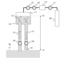
- FIG. 1 is a schematic diagram of a carbon dioxide capture device according to a first embodiment of the present invention
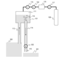
- FIG. 5 is a schematic diagram of a carbon dioxide capture device according to a second embodiment of the present invention.
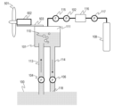
- FIG. 11 is a schematic diagram of a carbon dioxide capture device according to a third embodiment of the present invention.
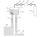
- FIG. 13 is a schematic diagram of a carbon dioxide capture device according to a fourth embodiment of the present invention.
- FIG. 13 is a schematic diagram of a carbon dioxide capture device according to a fifth embodiment of the present invention.
- FIG. 13 is a schematic diagram of a carbon dioxide capture device according to a sixth embodiment of the present invention.
- FIG. 13 is a schematic diagram of a carbon dioxide capture device according to a sixth embodiment of the present invention.
- FIG. 13 is a schematic diagram of a carbon dioxide capture device according to a sixth embodiment of the present invention.
- FIG. 13 is a schematic diagram of a carbon dioxide capture device according to a seventh embodiment of the present invention.
- FIG. 13 is a schematic diagram of a carbon dioxide capture device according to an eighth embodiment of the present invention.
- FIG. 13 is a schematic diagram of a carbon dioxide capture device according to a ninth embodiment of the present invention.
- a carbon dioxide capture device captures carbon dioxide from the atmosphere at low cost by heating or reducing pressure in a liquid in which carbon dioxide is dissolved.
- liquids in which carbon dioxide is dissolved include rainwater, river water, lake water, and seawater.
- fresh water such as rainwater and river water
- atmospheric carbon dioxide is dissolved at an equilibrium pressure.
- seawater has an even higher solubility of carbon dioxide.
- the solubility of carbon dioxide in water is high at low temperatures and low at high temperatures. Additionally, the higher the air pressure, the higher the solubility of carbon dioxide, and the lower the air pressure, the lower the solubility.
- the carbon dioxide capture device can capture carbon dioxide at low cost with a simple device configuration. Specifically, seawater or freshwater is pumped, the carbon dioxide released from the storage section is captured, and the seawater or freshwater is circulated within the device using the siphon principle.
- the storage section is a Torricelli vacuum (a vacuum space formed at the top as water is pumped), and the Torricelli vacuum refers to a vacuum space created in a space that exceeds the height that is the positional limit at which water can be pumped by reducing pressure.
- a Torricelli vacuum is formed due to the relationship between atmospheric pressure, the specific gravity of the solution, and the vapor pressure of the solution, and when water is at sea level, a Torricelli vacuum occurs when it exceeds approximately 10 m.
- reducing pressure in the storage section is not essential, and the device may be configured so that carbon dioxide is released by heating with a heating mechanism.
- the carbon dioxide dissolved in seawater or freshwater is released as a gas in response to the Torricelli vacuum, so that the carbon dioxide can be discharged by a vacuum pump and captured in a capture tank.
- the carbon dioxide capture device of the present invention also utilizes, for example, the siphon principle to circulate the pumped seawater or freshwater within the device under reduced pressure. Note that the method of circulation within the device is not limited to the siphon principle, and other known technologies may be used as long as they are a mechanism for circulating liquid.
- the pressure density due to the weight of the liquid in the water supply channel and the pressure density of the liquid in the drain channel will be the same if the positional heights of the water supply channel and the drain channel are the same.
- the liquid can be made to flow from the water supply side to the drain side by potential energy without power assistance such as a water flow pump.
- the liquid can be circulated within the device by providing slight power assistance from a water flow pump.
- the carbon dioxide capture device of the present invention is capable of capturing carbon dioxide with low energy in the carbon dioxide capture device. Furthermore, the present invention further enables the capture of carbon dioxide from liquid at low cost by transmitting vibrations to the liquid, i.e., by vibrating the liquid, as a means for shortening the reaction time for extracting carbon dioxide dissolved in the liquid as a gas. Furthermore, it is preferable to adopt a method in which the vibrations are generated by equipment that is a vibration source and is not intended to generate vibrations, and are transmitted to the liquid to vibrate it.
- the carbon dioxide capture device of the present invention is composed of a partition wall that separates the atmosphere from the internal space, and has a storage section that stores a liquid in which carbon dioxide is dissolved in the internal space.
- the device also has a vibration transmission section that transmits vibrations from the storage section or a vibration source that is arranged in close proximity to the storage section to the liquid stored in the storage section.
- the device is further characterized by having a storage section that collects and stores the carbon dioxide released from the liquid by the vibrations transmitted via the vibration transmission section, thereby allowing for low-cost carbon dioxide capture.
- the liquid 100 in which carbon dioxide from the atmosphere is dissolved is injected into the CO2 release tank (storage section) 101 by the injection pump 104 via the injection valve 105.
- the drain valve 107 is closed, and a space 111 is created in the liquid 100 inside the CO2 release tank (storage section) 101 by adjusting the amount of liquid injected.
- the injection valve 105 is closed.
- the valve 106 is opened and the inside of the CO2 release tank (storage section) 101 is depressurized by the vacuum pump 102.
- the degree of vacuum inside the CO2 release tank (storage section) 101 is set to 2 kPa, but the pressure may be higher than this as long as it is below atmospheric pressure, and the degree of vacuum is not limited.
- the vacuum pump 102 is physically connected to the CO2 release tank (storage section) 101 via the vibration transmission section 103.
- the vibrations generated by the exhaust operation of the vacuum pump 102, which is the vibration source, are transmitted to the liquid inside the storage section by the vibration transmission section 103.
- the vibrations are transmitted to the liquid 100 inside the CO2 release tank (storage section) 101 via the CO2 release tank (storage section) 101.
- the vibrations of the vibration source arranged close to the storage section 101 are transmitted to the liquid stored in the storage section 101 via the vibration transmission section 103.
- the reduced pressure causes the liquid 100 to have an excess of dissolved carbon dioxide compared to the pressure equilibrium, and carbon dioxide is released from the liquid 100 into the storage section 101. Furthermore, the carbon dioxide is released from the liquid 100 into space 111 as bubbles 110 due to vibrations generated by the vacuum pump 102. The carbon dioxide released into space 111 is collected from the release tank 101 by the vacuum pump 102 and stored in the CO2 storage section (storage section) (storage section) 108.
- the depressurization time for the liquid 100 is set to 3 minutes, but the depressurization time is not limited thereto, and by lengthening the depressurization time, the recovery rate of carbon dioxide from the liquid 100 by the carbon dioxide recovery device is improved. However, by lengthening the depressurization time, the amount of carbon dioxide remaining in the liquid 100 decreases, and therefore the amount of carbon dioxide that can be recovered per hour decreases.
- the valve 106 is closed and the vacuum pump 102 is stopped.
- the atmospheric leak valve 122 is opened to bring the space 111 to atmospheric pressure, and the drain valve 107 is opened to drain the liquid 100 from the CO2 release tank (storage section) 101.
- the drain valve 107 is closed, completing a series of carbon dioxide recovery operations. The series of operations described above is repeated to recover carbon dioxide from the atmosphere.
- seawater was used as the liquid 100 with dissolved carbon dioxide, but the liquid is not limited to seawater as long as it contains dissolved carbon dioxide from the atmosphere, and may be rainwater, river water, lake water, or tap water.
- the liquid 100 may also be a basic aqueous solution or a fluorine-based active liquid, and carbon dioxide in the atmosphere may be captured by exposing these liquids to the atmosphere. It is also possible to use the capture device in this embodiment to capture the CO2 in the captured liquid, and to use the liquid 100 after carbon dioxide capture to capture carbon dioxide in the atmosphere again as a circulation system device.
- the liquid 100 may be a basic solution for recovering CO2.
- basic substances include sodium hydroxide, ammonia, and amines (primary amines, secondary amines, and tertiary amines), and may be used as is or in solution. It may also be a solution of a salt such as sodium bicarbonate that is dissolved and shows basicity.
- borate, phosphate buffer, or Tris may be used as a buffer to suppress a sudden change in pH associated with the recovery of CO2. Recovery efficiency can be increased by using a fluorine-based active liquid with high CO2 solubility.
- the fluorine-based active liquid with high CO2 solubility is characterized in that it is selected from fluorocarbons that may have a substituent from the viewpoint of viscosity and may have a branched structure and/or a cyclic structure.
- fluorocarbons that may have a substituent from the viewpoint of viscosity and may have a branched structure and/or a cyclic structure.
- fluorocarbons that may have a substituent from the viewpoint of viscosity and may have a branched structure and/or a cyclic structure.
- fluorocarbons that may have a substituent from the viewpoint of viscosity and may have a branched structure and/or a cyclic structure.
- examples include perflubron, perfluorodecalin, Fluorinert FC-3283, perfluorobutyl perfluorotetrahydrofuran, perfluoro-1-isopropoxyhexane, perfluoro-1,4-diiso
- the vacuum pump 102 used in this embodiment is a vacuum pump driven by an induction motor that runs on a single-phase 100V, 50Hz commercial power source.
- the vibration of the vacuum pump which is the vibration source
- large vibrations were obtained at a few Hz or more, with peaks in the vibration amplitude being observed around 25Hz and 50Hz.
- the motor used is preferably a brushless motor, which is energy-efficient, and the typical control frequency is in the range of a few kHz to about 10 kHz.
- the drive current for a brushless motor is generated by amplifying the digital waveform resulting from the PWM signal generated by the drive frequency mentioned above using power transistors or FETs, and converting it into an analog current waveform using a low-pass filter.
- the pump's vibration frequency range is set to the aforementioned rotation speed and structure, and large vibrations can be obtained in the range of a few Hz to about 10 kHz, taking into account the control frequency.
- General brushless motors often have a maximum rotation speed of 6000 rpm, and at this rotation speed the rotation frequency of the motor alone is 100 Hz or less. Vibrations can also be generated by controlling the motor's rotation speed to cause unevenness, for example by controlling the motor drive current so that the vibration caused by cogging in the brushless motor is increased. For example, in the case of a motor driven by a three-phase current, the vibration caused by cogging is often a product consisting of about five sets of three-phase coils, and cogging vibration occurs about 15 times per motor rotation.
- Brushless motors come in a wide variety of configurations, so the coil configuration described above is just one example.
- the vibration frequency generated varies depending on the structure of the gears and screws that make up the pump.
- a part of the pump structure may be configured with a gear that rotates at high speed, generating high frequency vibrations. It is generally known that vibration energy is greater at higher frequencies for the same amplitude, and there is no limit to the vibration frequency as long as it promotes the generation of bubbles 110 from the liquid 100.
- the vibration transmission part 103 uses a metal member made of iron.
- the vacuum pump 102, which is the vibration source, and the CO2 release tank (storage part) 101 are fixed with the metal member described above.
- the vibration transmission part 103 is not limited to the metal member made of iron described above as long as it can transmit the vibration of the vacuum pump 102, which is the vibration source, to the liquid 100, and may be, for example, SUS, an alloy of aluminum or copper, or a resin material.
- the vibration transmission part 103 may also be an exhaust pipe for reducing the pressure inside the CO2 release tank (storage part) 101, and the vacuum pump 102 may be installed on the device stand 124, which may serve as the vibration transmission part 103.
- the CO2 release tank (storage section) 101 is supported on a mounting section such as an apparatus stand 124 via an elastic section 123, and is structured so that the CO2 release tank (storage section) 101 is easily vibrated.
- a rubber member is used for the elastic section 123, but it may also be a structure made of metal, resin, or wood with spring properties, or a damper structure.
- the mounting section is not limited to the stand, and may be the ground, etc.
- the liquid 100 in the storage section 101 may be heated by a heating section 109 consisting of a heating mechanism.
- the heating section 109 is preferably a heat source that does not release new carbon dioxide into the atmosphere for heating, and is preferably one that uses factory waste heat, solar-based energy, geothermal energy, or green electricity, for example.
- the solution 100 in which carbon dioxide is in atmospheric pressure equilibrium will release carbon dioxide not only by reducing the pressure but also by increasing the solution temperature, so it is desirable to heat the solution as well as reducing the pressure.
- the liquid 100 in which carbon dioxide is dissolved is seawater, and the CO2 release tank (storage section) 101 is installed so that the pumping height H2 of the liquid 100 inside the CO2 release tank (storage section) 101 is approximately 10 m above the seawater level H2.
- the liquid 100 is pumped by a pumping pump 104 through a water supply pipe 113 into the CO2 release tank (storage section) 101 in the flow shown by the arrow.
- the pressure inside the CO2 release tank (storage section) 101 is reduced by the vacuum pump 102.
- the liquid 100 pumped from the water supply port is stored inside the CO2 release tank (storage section) 101 in an amount based on the shape of the CO2 release tank (storage section) 101 and the pumping height H2.
- the pumped liquid 100 is drained from the drain outlet 118 by the drain pipe 114 and drain pump 106 as a flow shown by the arrow.
- the space 111 is decompressed to 2 kPa.
- the height relationship between the water supply pipe 113 and the drain pipe 114 inside the CO2 release tank (storage section) 101 is preferably the height relationship at which the liquid 100 with a reduced residual carbon dioxide concentration is drained, and is not limited as this height relationship differs depending on the liquid 100 that is the solvent.
- the liquid 100 is drained by the drain pump 106, but the upper limit of the pumping height H2 is determined by a principle called the "Torricelli vacuum height", and when pumping seawater at sea level 0 m, the pumping height H2 is about 10 m.
- the Torricelli vacuum height is determined by the relationship between the vapor pressure of the liquid 100, the weight density of the liquid 100, and the atmospheric pressure at the sea level H1.
- the carbon dioxide capture device in this embodiment is equipped with a water supply pipe 113, which is a structure that suppresses the flow rate of the water supply path that supplies the liquid to the storage unit 101, and a drain pipe 114, which is a drainage mechanism that drains the liquid from the storage unit.
- the liquid level of the liquid inside the storage unit 101 is lower than the Torricelli vacuum height in the storage unit.
- the liquid level of the liquid 100 described above changes depending on the air pressure, the temperature of the liquid 100, the degree of vacuum inside the CO2 release tank (storage unit) 101, and the constituent elements of the liquid 100.
- the pumping height H2 is the Torricelli vacuum height
- the liquid 100 will be drained by its own weight even without the drainage pump 106, so the configuration may not require the drainage pump 106.
- the pumping height H2 can be set to any height below the Torricelli vacuum height.
- the pumping height H2 may be adjusted by reducing the supply flow rate of the liquid 100 using a flow rate suppression mechanism and draining the liquid using the drainage pump 106.
- the flow rate suppression mechanism described above needs only to increase the flow resistance of the water being supplied, and may be, for example, a configuration in which a flow rate adjustment valve is provided in the water supply pipe 113, or a configuration in which the diameter of the water supply pipe 113 is narrowed.
- the liquid 100 can be drained using the drainage pump 106. Specifically, even if the configuration does not have the pumping pump 104, the liquid 100 is pumped due to the relationship between the pressure inside the CO2 release tank (storage section) 101 and the atmospheric pressure to which the liquid 100 is subjected. Therefore, from the viewpoint of power saving, it is desirable to use either the pumping pump 104 or the drainage pump 106.
- the liquid 100 is circulated within the device by the siphon principle, so when circulating the liquid 100 by pumping with the pump pump 104, for example, only a small amount of pumping is required, so the liquid can be circulated with little pump drive power.
- the carbon dioxide released into the reduced pressure space 111 is collected by the vacuum pump 102 through the water vapor filter 115, temporarily stored in the carbon dioxide buffer tank 116, and then stored in the CO2 storage unit (accumulation unit) 108 by the pressure pump 117.
- the collected carbon dioxide is stored in the CO2 storage unit (accumulation unit) 108 at a pressure equal to or higher than atmospheric pressure.
- the water supply pipe 113 is a vibration transmission part that transmits the vibration of the water lifting pump 104, which is a vibration source, to the liquid 100 inside the CO2 release tank (storage section) 101.
- the drain pipe 114 is a vibration transmission part that transmits the vibration of the drainage pump 106.
- stainless steel pipes are used for the water supply pipe 113 and the drain pipe 114, the material is not limited.
- the vibration of the drainage pump 106 is transmitted to the storage section 111 by the vibration of the drain pipe 114, which is a vibration transmission part, causing it to vibrate, thereby releasing further carbon dioxide from the liquid in the storage section 101.
- the vibration of the vacuum pump may be transmitted via a vibration transmission unit, or may be implemented in appropriate combination with any of the vibration transmission units described above.
- the vibration frequency of a water lift pump or drainage pump varies depending on the motor's rotation speed, the number of blades that generate the water flow, and other structural factors. It is generally known that the higher the frequency, the greater the vibration energy will be for the same amplitude, and there is no limit to the vibration frequency as long as it can promote the generation of bubbles 110 from the liquid 100.
- the liquid 100 is seawater, but it can be any liquid in which carbon dioxide is dissolved, such as rainwater, river water, lake water, tap water, a basic aqueous solution, or a fluorine-based active liquid, and is not limited to seawater.
- it can be combined with the configuration described in the first embodiment in which the liquid 100 is exposed to the atmosphere to capture carbon dioxide in the atmosphere, to form a circulating carbon dioxide capture device.
- the liquid 300 in which carbon dioxide is dissolved is river water, and the height of the drain outlet 118, which is the drain surface, is lower than the height of the surface of the liquid 300, which is the water supply surface where the water supply inlet is located.
- the water supply inlet is also provided vertically above the drain outlet.
- the carbon dioxide capture device is configured in this way, so that the supplied liquid 300 can be circulated and drained inside the carbon dioxide capture device using the siphon principle without requiring a power source to move the liquid.
- the drain outlet 118 and the drained liquid 301 are configured not to come into contact with each other, but contact is not an issue as long as the configuration allows drainage using the siphon principle.
- a hydraulic generator 302 is attached to the flow path of the drain pipe 114, and hydroelectric power is generated based on the potential energy associated with the drainage of the liquid 300.
- the power generated by the generator 302 is used as the power source for the vacuum pump 102, the pressure pump 117, and the device control system.
- the vibrations generated by the generator 302 are transmitted to the liquid 300 in the storage section 101 by the drain pipe 114, which is a vibration transmission section.
- the vibration frequency caused by the generator 302 generating electricity varies depending on the number of blades that convert the water flow into rotational motion and the number of rotations of the generator, but the vibration amplitude and vibration frequency are not limited as long as they can promote the generation of bubbles 110 from the carbon dioxide dissolved in the liquid 300.
- the material of the drain pipe 114 is stainless steel pipe, but it may also be polyvinyl chloride pipe or iron pipe, and the material is not limited.
- the height of the liquid surface of the liquid 300 varies depending on the atmospheric pressure, the temperature of the liquid 300, the degree of vacuum inside the CO2 release tank (storage section) 101, and the constituent elements of the liquid 300.
- the degree of vacuum inside the CO2 release tank (storage section) 101 is set to about 2 kPa
- the height from the air contact surface of the liquid 300 to the liquid surface of the liquid 300 inside the CO2 release tank (storage section) 101 is set to about 10 m.
- the length of the drain pipe 114 is set to 10 m or more, so that the generator 302 can obtain sufficient potential energy of the liquid 300 to generate electricity.
- a mechanism for floating on the water surface is provided in addition to the carbon dioxide device configuration in the second embodiment.
- the liquid 400 in which carbon dioxide is dissolved is seawater, but it may be fresh water such as river water or lake water.
- the floating body 401 is, for example, the hull of a ship, and has an engine 402, which is an internal combustion engine for the purpose of sailing the ship. That is, the vibration source in this embodiment is, for example, the ship's propulsion engine.
- the engine 402 may also be an engine for generating electricity, and the use of the engine is not limited, and for example, the vibration source may be a power generation engine.
- the floating body 401 is a ship, but it may be any structure that floats on the water surface, for example, it may be a wind power generator floating on the ocean.
- the vibration frequency generated by the engine 402 changes depending on the rotation speed as an internal combustion engine.
- the vibration generated by the engine 402 is transmitted via the float 401 to the water supply pipe 113 and the drain pipe 114, and then to the liquid 400 inside the CO2 release tank (storage section) 101.
- the vibration generated by the engine 402 promotes the release of carbon dioxide from the liquid 400 inside the CO2 release tank (storage section) 101.
- the water supply pipe 113 and the drain pipe 114 are the vibration transmission sections, but a separate structure that serves as the vibration transmission section may also be provided.
- the liquid 400 is seawater and the floating body 401 floats on the seawater, it sways due to wave forces caused by weather.
- the liquid 400 inside the CO2 release tank (storage section) 101 sways.
- the vibration frequency of the hull due to the influence of wave forces varies depending on the size and structure of the hull, but is approximately 0.1 Hz to 1 Hz.
- the CO2 release tank (storage section) 101 is installed at a height of about 10 m above sea level, the vibration amplitude due to the influence of wave forces is large, which promotes the release of carbon dioxide from the liquid 400 inside the CO2 release tank (storage section) 101.
- the height of the liquid surface of the liquid 400 mentioned above changes depending on the air pressure, the temperature of the liquid 400, the degree of vacuum inside the CO2 release tank (storage section) 101, and the constituent elements of the liquid 100.
- the purpose of the buffer tank 404 is to prevent the vacuum pump 102 from sucking in the liquid 400 inside the CO2 release tank (storage section) 101 when the floating body 401 sways significantly due to the effects of waves, and prevents a small amount of liquid 400 from flowing into the vacuum pump 102.
- the CO2 release tank (storage section) 101 and the buffer tank 404 are configured as separate tanks, but a partition plate may be attached inside the CO2 release tank (storage section) 101 to provide separate rooms.
- the valve 403 is closed to prevent the liquid 400 from flowing into the vacuum pump 102.
- a sensor is provided to detect the tilt of the hull, and the valve 403 is automatically closed when the tilt exceeds a certain level.
- the heat generated by the engine 402 is transferred to the liquid 400 via the water supply pipe 113, but a separate heat transfer mechanism may be provided to transfer the heat generated by the engine 402 to the liquid 400.
- a separate heat transfer mechanism may be provided to transfer the heat generated by the engine 402 to the liquid 400.
- This embodiment is a configuration in which a mechanism for generating electricity using wind power is added to the configuration in the second embodiment. It has a windmill 501, a generator 502 that generates electricity by the rotation of the windmill, and a vibration transmission part 503 that transmits the vibration of the generator to the liquid 400 inside the CO2 release tank (storage part) 101.
- the material of the vibration transmission part 503 is an iron member, but the material is not limited thereto.
- the vibration frequency of the generator 502 varies depending on the structure, such as the rotational speed of the windmill and the number of blades. Wind power generators often generate vibrations in the low frequency range of several tens of Hz or less. It is generally known that the higher the frequency, the greater the vibration energy will be for the same amplitude, and a larger amplitude will promote the release of carbon dioxide from the liquid 100. There are no limitations on the vibration frequency as long as it promotes the generation of bubbles 110 from the liquid 100.
- the height of the liquid surface of the liquid 100 inside the CO2 release tank (storage section) 101 is set to about 10 m from the height of the water intake surface.
- the height of the liquid surface of the liquid 100 described above varies depending on the air pressure, the temperature of the liquid 100, the degree of vacuum inside the CO2 release tank (storage section) 101, and the constituent elements of the liquid 100.
- the CO2 release tank (storage section) 101 is installed at a predetermined height by a structure (not shown) built on the ground.
- the CO2 release tank (storage section) 101 is structured to swing left and right and front and back due to the elasticity of the structure caused by wind force.
- the CO2 release tank (storage section) 101 swings, causing the liquid 100 inside the CO2 release tank (storage section) 101 to vibrate, promoting the release of carbon dioxide from the liquid 100.
- the windmill 501 and the generator 502 are installed near the CO2 release tank (storage section) 101, but it is sufficient that the vibration can be transmitted to the CO2 release tank (storage section) 101 by the vibration transmission section 503.
- the windmill 501 and the generator 502 may be installed at a height of about 40 m, and the positional relationship is not limited.
- the structure described above is made of iron material, but it may be made of metals and alloys such as stainless steel and aluminum, concrete, or wood, and the material is not limited.
- the liquid 100 is seawater, but it may be fresh water.
- the configuration in this embodiment may also be combined with the floating body 401 described in embodiment 4.
- the configuration is provided with two pumps, the lifting pump 104 and the drainage pump 106, but the liquid 100 can be circulated if either one of the pumps is provided, and the pump configuration is not limited.
- a CO2 release tank (storage unit) 101 and a vacuum pump 102 are installed on the vibration transmission unit 103.
- the vacuum pump 102 is ULVAC model number: DA-20D, and when the vibration frequency was measured, the main vibration frequency peak was 50 Hz.
- the vibration transmission unit 103 was the top plate of a typical stainless steel laboratory equipment rack, and the elastic unit 123 was a plastic caster for the rack.
- the piping connecting the vacuum pump 102 to the water vapor filter 115, and the piping connecting the vacuum pump 102 to the carbon dioxide buffer tank 116 are made of flexible plastic piping, allowing the installation position of the vacuum pump 102 to be easily changed.
- Figure 6B shows the results of measuring the change in CO2 capture volume over time when the vacuum pump 102 is installed on the vibration transmission part 103 and when it is installed on the device stand 124.
- the liquid 100 is seawater, and the measurement was performed with the inlet valve 105 and the outlet valve 107 closed and the liquid 100 not circulating.
- the vacuum pump 102 is installed on the vibration transmission part 103, more CO2 can be captured in a shorter time than when it is installed on the device stand 124.
- the CO2 capture rate was increased when the vacuum pump 102 was moved to a different location on top of the vibration transmission unit 103 during the measurement.
- This measurement was performed without circulating the liquid 100 for measurement purposes, but the injection valve 105 and drain valve 107 may be opened to circulate the liquid using the drain pump 601 to continuously collect carbon dioxide.
- the model number of the vacuum pump 102 was used for measurement experiments, and does not limit the model number or type of the vacuum pump.
- the method of circulating the liquid 100 may also be a method of draining the liquid 100 from the CO2 release tank (storage section) 101 and then refilling it with water. Or, when draining the liquid, a method of returning the internal pressure of the CO2 release tank (storage section) 101 to atmospheric pressure may also be used, and the method of circulating the liquid is not limited.
- this example is configured by providing a structure inside the water supply pipe 113 that narrows the width of the flow path, and by providing a vibration generating unit 701 that generates vibrations due to changes in the water flow.
- the vibration generating unit 701 causes local changes in water pressure in the liquid 100, which causes cavitation or the water hammer phenomenon, resulting in vibrations.
- the vibration generating unit 701 is characterized by transmitting vibrations generated by at least one of cavitation and the water hammer phenomenon, which are caused by local changes in water pressure inside the liquid due to the flow of the liquid.
- the vibrations generated by the vibration generating unit 701 are transmitted to the liquid 100 inside the CO2 release tank (storage unit) 101 by the water supply pipe 113, which is the vibration transmitting unit.
- the vibration generating unit 701 only needs to generate vibrations by changing the water flow, and the structure of the vibration generating unit 701 may be, for example, a screw, a floating metal sphere, stone grain, or piece of wood, marine organisms such as crustaceans or shellfish, or marine plants such as seaweed.
- the vibration generating unit 701 is made of stainless steel, but the material is not limited to this.
- the liquid 100 is river water, and the liquid level of the liquid 100 is described as being in a positional relationship in which the water supply side liquid level 300 is higher than the water discharge side liquid level 301, and the liquid 100 circulates according to the siphon principle.
- it may also be configured to circulate seawater, in which the water supply side liquid level 300 and the water discharge side liquid level 301 are the same level, using a circulation pump.
- the liquid level of the liquid 100 is higher on the water supply side 300 than on the drain side 301, and the liquid 100 flows due to the difference between atmospheric pressure and the pressure inside the CO2 release tank (storage section) 101.
- the flow rate of the liquid 100 injected into the CO2 release tank (storage section) 101 is adjusted by the injection valve 105. Vibrations caused by the liquid 100 passing through the injection valve 105 are transmitted to the liquid 100 inside the CO2 release tank (storage section) 101 by the water supply pipe 113, which is a vibration transmission section.
- the liquid 100 inside the CO2 release tank (storage section) 101 is configured to be drained from the drain outlet 118 by its own weight, but it may also be drained by providing a separate auxiliary circulation pump for the purpose of drainage.
- the liquid 100 poured into the CO2 release tank (storage section) 101 is caused to collide with the vibration transmission section 901 to generate vibrations, which are then transmitted to the liquid 100.
- the vibrations generated by the collision are transmitted to the entire liquid 100 in the CO2 release tank by the liquid 100 inside the CO2 release tank (storage section) 101.
- the injected liquid 100 is configured to collide with the vibration transmission unit 901 to generate vibrations.
- it may also be configured to collide with the liquid 100 inside the CO2 release tank (storage unit) 101, and transmit the generated collision energy to the vibration transmission unit 901 via the liquid 100.
- the vibration transmission unit 901 may transmit vibrations generated by the injected liquid colliding with the liquid stored in the storage unit.
Landscapes
- Chemical & Material Sciences (AREA)
- Engineering & Computer Science (AREA)
- Environmental & Geological Engineering (AREA)
- Chemical Kinetics & Catalysis (AREA)
- General Chemical & Material Sciences (AREA)
- Analytical Chemistry (AREA)
- Health & Medical Sciences (AREA)
- Oil, Petroleum & Natural Gas (AREA)
- Biomedical Technology (AREA)
- Life Sciences & Earth Sciences (AREA)
- Hydrology & Water Resources (AREA)
- Water Supply & Treatment (AREA)
- Organic Chemistry (AREA)
- Mechanical Engineering (AREA)
- Physical Or Chemical Processes And Apparatus (AREA)
Abstract
Priority Applications (2)
| Application Number | Priority Date | Filing Date | Title |
|---|---|---|---|
| EP24819315.3A EP4725913A1 (fr) | 2023-06-07 | 2024-06-04 | Dispositif et procédé de récupération de dioxyde de carbone |
| US19/391,761 US20260077308A1 (en) | 2023-06-07 | 2025-11-17 | Carbon dioxide capture apparatus and carbon dioxide capture method |
Applications Claiming Priority (4)
| Application Number | Priority Date | Filing Date | Title |
|---|---|---|---|
| JP2023094138 | 2023-06-07 | ||
| JP2023-094138 | 2023-06-07 | ||
| JP2024-075197 | 2024-05-07 | ||
| JP2024075197A JP2024177076A (ja) | 2023-06-07 | 2024-05-07 | 二酸化炭素の回収装置、および、二酸化炭素の回収方法 |
Related Child Applications (1)
| Application Number | Title | Priority Date | Filing Date |
|---|---|---|---|
| US19/391,761 Continuation US20260077308A1 (en) | 2023-06-07 | 2025-11-17 | Carbon dioxide capture apparatus and carbon dioxide capture method |
Publications (1)
| Publication Number | Publication Date |
|---|---|
| WO2024253086A1 true WO2024253086A1 (fr) | 2024-12-12 |
Family
ID=93796051
Family Applications (1)
| Application Number | Title | Priority Date | Filing Date |
|---|---|---|---|
| PCT/JP2024/020355 Ceased WO2024253086A1 (fr) | 2023-06-07 | 2024-06-04 | Dispositif et procédé de récupération de dioxyde de carbone |
Country Status (3)
| Country | Link |
|---|---|
| US (1) | US20260077308A1 (fr) |
| EP (1) | EP4725913A1 (fr) |
| WO (1) | WO2024253086A1 (fr) |
Citations (8)
| Publication number | Priority date | Publication date | Assignee | Title |
|---|---|---|---|---|
| JPS575099Y2 (fr) * | 1980-02-21 | 1982-01-30 | ||
| JPS5835905U (ja) * | 1981-08-31 | 1983-03-09 | 株式会社日立製作所 | 液中の脱ガス装置 |
| JPH0445884A (ja) * | 1990-06-11 | 1992-02-14 | Abb Gadelius Kk | 海水淡水化装置 |
| JP2003259759A (ja) | 2002-03-07 | 2003-09-16 | Japan Aqua Tec Co Ltd | 魚類飼育水槽の二酸化炭素除去装置 |
| WO2014080875A1 (fr) * | 2012-11-20 | 2014-05-30 | 株式会社クレハ | Séparateur gaz-liquide |
| JP2023094138A (ja) | 2021-12-23 | 2023-07-05 | 合同会社加速流グリーンパワー研究所 | 風車発電装置 |
| JP2024075197A (ja) | 2022-11-22 | 2024-06-03 | Juniverse株式会社 | プログラム、方法、及び情報処理装置 |
| JP2024076153A (ja) * | 2022-11-24 | 2024-06-05 | キヤノン株式会社 | 二酸化炭素の回収装置、二酸化炭素の回収方法、二酸化炭素の回収方法を用いた植物育成方法、および植物育成機構 |
-
2024
- 2024-06-04 EP EP24819315.3A patent/EP4725913A1/fr active Pending
- 2024-06-04 WO PCT/JP2024/020355 patent/WO2024253086A1/fr not_active Ceased
-
2025
- 2025-11-17 US US19/391,761 patent/US20260077308A1/en active Pending
Patent Citations (8)
| Publication number | Priority date | Publication date | Assignee | Title |
|---|---|---|---|---|
| JPS575099Y2 (fr) * | 1980-02-21 | 1982-01-30 | ||
| JPS5835905U (ja) * | 1981-08-31 | 1983-03-09 | 株式会社日立製作所 | 液中の脱ガス装置 |
| JPH0445884A (ja) * | 1990-06-11 | 1992-02-14 | Abb Gadelius Kk | 海水淡水化装置 |
| JP2003259759A (ja) | 2002-03-07 | 2003-09-16 | Japan Aqua Tec Co Ltd | 魚類飼育水槽の二酸化炭素除去装置 |
| WO2014080875A1 (fr) * | 2012-11-20 | 2014-05-30 | 株式会社クレハ | Séparateur gaz-liquide |
| JP2023094138A (ja) | 2021-12-23 | 2023-07-05 | 合同会社加速流グリーンパワー研究所 | 風車発電装置 |
| JP2024075197A (ja) | 2022-11-22 | 2024-06-03 | Juniverse株式会社 | プログラム、方法、及び情報処理装置 |
| JP2024076153A (ja) * | 2022-11-24 | 2024-06-05 | キヤノン株式会社 | 二酸化炭素の回収装置、二酸化炭素の回収方法、二酸化炭素の回収方法を用いた植物育成方法、および植物育成機構 |
Also Published As
| Publication number | Publication date |
|---|---|
| US20260077308A1 (en) | 2026-03-19 |
| EP4725913A1 (fr) | 2026-04-15 |
Similar Documents
| Publication | Publication Date | Title |
|---|---|---|
| US8568588B2 (en) | Apparatus for osmotic power generation and desalination using salinity difference | |
| CN103047085A (zh) | 一种深海能源综合利用系统 | |
| CN101675243A (zh) | 用于采集自然运动流体的动能的设备及方法 | |
| WO2014207478A2 (fr) | Turbine flottante | |
| WO2009152258A2 (fr) | Procédés et systèmes de génération d’énergie | |
| CN202971047U (zh) | 一种深海能源综合利用系统 | |
| JP2002303454A (ja) | 浮体式水素酸素製造システム | |
| WO2024253086A1 (fr) | Dispositif et procédé de récupération de dioxyde de carbone | |
| JP2024177076A (ja) | 二酸化炭素の回収装置、および、二酸化炭素の回収方法 | |
| CN101749167A (zh) | 正倒虹吸式海浪发电方法及发电机 | |
| JP2000352371A (ja) | 圧縮空気貯蔵複合発電システム | |
| WO2010124697A3 (fr) | Flottaison sur des pontons de dessalement et centrale tandem de génération d'électricité | |
| US20120200088A1 (en) | Sipoline Hydro Electric Generator | |
| JP2024076153A (ja) | 二酸化炭素の回収装置、二酸化炭素の回収方法、二酸化炭素の回収方法を用いた植物育成方法、および植物育成機構 | |
| JP2005023799A (ja) | 沈水式発電装置 | |
| CN204663751U (zh) | 一种高效水流发电装置 | |
| JP2012189071A (ja) | 海水圧高圧噴出発電装置 | |
| CN209833924U (zh) | 一种用于清理水面污物的船 | |
| JP2025166647A (ja) | 液体中に溶存するガスの回収システム | |
| CN220185266U (zh) | 海水发电装置 | |
| CN211343202U (zh) | 潮汐能发电装置及发电系统 | |
| EP4421314A1 (fr) | Éolienne offshore et procédé de fonctionnement d'une éolienne offshore | |
| KR20160011350A (ko) | 자가발전 워터젯 고속추진체 | |
| WO2007071161B1 (fr) | Equipement generateur d'electricite fonctionnant a l'energie marine, a l'energie hydraulique et a l'energie eolienne | |
| CN102278316A (zh) | 一种水陆两栖立式离心泵机组 |
Legal Events
| Date | Code | Title | Description |
|---|---|---|---|
| 121 | Ep: the epo has been informed by wipo that ep was designated in this application |
Ref document number: 24819315 Country of ref document: EP Kind code of ref document: A1 |
|
| WWE | Wipo information: entry into national phase |
Ref document number: 2024819315 Country of ref document: EP |
|
| NENP | Non-entry into the national phase |
Ref country code: DE |
|
| ENP | Entry into the national phase |
Ref document number: 2024819315 Country of ref document: EP Effective date: 20260107 |
|
| ENP | Entry into the national phase |
Ref document number: 2024819315 Country of ref document: EP Effective date: 20260107 |
|
| ENP | Entry into the national phase |
Ref document number: 2024819315 Country of ref document: EP Effective date: 20260107 |
|
| ENP | Entry into the national phase |
Ref document number: 2024819315 Country of ref document: EP Effective date: 20260107 |
|
| ENP | Entry into the national phase |
Ref document number: 2024819315 Country of ref document: EP Effective date: 20260107 |
|
| WWP | Wipo information: published in national office |
Ref document number: 2024819315 Country of ref document: EP |