WO2024256728A1 - Procede et dispositif de controle des puissances d'un reseau alternatif triphase par hybridation parallele avec un onduleur pilote et une source dc - Google Patents
Procede et dispositif de controle des puissances d'un reseau alternatif triphase par hybridation parallele avec un onduleur pilote et une source dc Download PDFInfo
- Publication number
- WO2024256728A1 WO2024256728A1 PCT/EP2024/066847 EP2024066847W WO2024256728A1 WO 2024256728 A1 WO2024256728 A1 WO 2024256728A1 EP 2024066847 W EP2024066847 W EP 2024066847W WO 2024256728 A1 WO2024256728 A1 WO 2024256728A1
- Authority
- WO
- WIPO (PCT)
- Prior art keywords
- main network
- power value
- network
- power
- electrical load
- Prior art date
- Legal status (The legal status is an assumption and is not a legal conclusion. Google has not performed a legal analysis and makes no representation as to the accuracy of the status listed.)
- Ceased
Links
Classifications
-
- H—ELECTRICITY
- H02—GENERATION; CONVERSION OR DISTRIBUTION OF ELECTRIC POWER
- H02J—ELECTRIC POWER NETWORKS; CIRCUIT ARRANGEMENTS OR SYSTEMS FOR SUPPLYING OR DISTRIBUTING ELECTRIC POWER; SYSTEMS FOR STORING ELECTRIC ENERGY
- H02J3/00—Circuit arrangements for AC mains or AC distribution networks
- H02J3/38—Arrangements for feeding a single network from two or more generators or sources in parallel; Arrangements for feeding already energised networks from additional generators or sources in parallel
- H02J3/46—Controlling the sharing of generated power between the generators, sources or networks
- H02J3/48—Controlling the sharing of active power
-
- H—ELECTRICITY
- H02—GENERATION; CONVERSION OR DISTRIBUTION OF ELECTRIC POWER
- H02J—ELECTRIC POWER NETWORKS; CIRCUIT ARRANGEMENTS OR SYSTEMS FOR SUPPLYING OR DISTRIBUTING ELECTRIC POWER; SYSTEMS FOR STORING ELECTRIC ENERGY
- H02J3/00—Circuit arrangements for AC mains or AC distribution networks
- H02J3/38—Arrangements for feeding a single network from two or more generators or sources in parallel; Arrangements for feeding already energised networks from additional generators or sources in parallel
- H02J3/381—Dispersed generators
-
- H—ELECTRICITY
- H02—GENERATION; CONVERSION OR DISTRIBUTION OF ELECTRIC POWER
- H02J—ELECTRIC POWER NETWORKS; CIRCUIT ARRANGEMENTS OR SYSTEMS FOR SUPPLYING OR DISTRIBUTING ELECTRIC POWER; SYSTEMS FOR STORING ELECTRIC ENERGY
- H02J3/00—Circuit arrangements for AC mains or AC distribution networks
- H02J3/38—Arrangements for feeding a single network from two or more generators or sources in parallel; Arrangements for feeding already energised networks from additional generators or sources in parallel
- H02J3/46—Controlling the sharing of generated power between the generators, sources or networks
- H02J3/50—Controlling the sharing of reactive power
-
- B—PERFORMING OPERATIONS; TRANSPORTING
- B64—AIRCRAFT; AVIATION; COSMONAUTICS
- B64D—EQUIPMENT FOR FITTING IN OR TO AIRCRAFT; FLIGHT SUITS; PARACHUTES; ARRANGEMENT OR MOUNTING OF POWER PLANTS OR PROPULSION TRANSMISSIONS IN AIRCRAFT
- B64D2221/00—Electric power distribution systems onboard aircraft
-
- H—ELECTRICITY
- H02—GENERATION; CONVERSION OR DISTRIBUTION OF ELECTRIC POWER
- H02J—ELECTRIC POWER NETWORKS; CIRCUIT ARRANGEMENTS OR SYSTEMS FOR SUPPLYING OR DISTRIBUTING ELECTRIC POWER; SYSTEMS FOR STORING ELECTRIC ENERGY
- H02J2105/00—Networks for supplying or distributing electric power characterised by their spatial reach or by the load
- H02J2105/30—Networks for supplying or distributing electric power characterised by their spatial reach or by the load the load networks being external to vehicles, i.e. exchanging power with vehicles
- H02J2105/32—Networks for supplying or distributing electric power characterised by their spatial reach or by the load the load networks being external to vehicles, i.e. exchanging power with vehicles for aircrafts
Definitions
- the invention relates to a method for managing the operation of an aircraft electrical power supply system comprising at least one electrical energy storage assembly.
- the electrical machines of an aircraft are currently sized to take into account electrical overloads of the network as well as the abnormal case of loss of an alternator on one side.
- these sizing powers are in fact rarely reached and are most often of short duration. This oversizing in power impacts the masses and volumes of the electrical machines and therefore more generally the energy consumption and emissions from the aircraft.
- the primary avionics electrical network involves variable power levels depending on the flight cycle and the needs.
- the invention aims to overcome all or part of the problems mentioned above by proposing a solution for supplementing power to the electrical network from a source other than traditional electrical machines such as a battery-type source and a converter.
- the invention relates to a method for supplying electrical energy to at least one electrical load in an aircraft electrical system, the aircraft electrical system comprising a main network and an auxiliary network, the main network comprising: - at least one source of alternating voltage by mechanical sampling on a drive system connected to a control unit of power generation, the alternating voltage source being connected to the at least one electrical load, the auxiliary network comprising: - at least one electrical energy storage assembly, configured to provide an energy supplement to the at least one electrical load, - a converter arranged between the electrical energy storage assembly and the at least one electrical load, configured to convert a direct current into an alternating current, - a converter control module, configured to measure a voltage between the at least one alternating voltage source and the at least one electrical load and to measure an electrical voltage between the
- the power supply method comprises a step of regulating the powers of the main network, following the step of calculating an apparent power value S in the main network, the step of regulating the powers of the main network comprising the following steps: - Observation of the characteristics of the main network and the auxiliary network, - Transformation of the active power value P of the main network and a reactive power value Q of the main network calculated according to a Park transformation, - Decoupling of the transformed active power value P of the main network and the transformed reactive power value Q of the main network, - Determination of a reference active power value ⁇ ⁇ ⁇ ⁇ in the main network, - Determination of a reference reactive power value ⁇ ⁇ ⁇ in the main network, - Regulation of the active power P of the main network by the reference active power value ⁇ ⁇ ⁇ ⁇ and of the reactive power Q of the main network by the reference reactive power value ⁇ ⁇ ⁇ ⁇ .
- the determined reference active power value ⁇ ⁇ ⁇ ⁇ of the main network is greater than the active power value P of the main network and the determined reference reactive power value ⁇ ⁇ ⁇ ⁇ of the main network is greater than the reactive power value Q.
- the determined reference active power value ⁇ ⁇ ⁇ ⁇ of the main network is greater than the active power value P of the main network and the determined reference reactive power value ⁇ ⁇ ⁇ ⁇ of the main network is less than the reactive power value Q of the main network.
- the determined reference active power value ⁇ ⁇ ⁇ ⁇ of the main network is less than the active power value P of the main network and the determined reference reactive power value ⁇ ⁇ ⁇ ⁇ of the main network is less than the reactive power value Q of the main network.
- the invention also relates to a device for supplying electrical energy to at least one electrical load in an aircraft electrical system, the aircraft electrical system comprising a main network and an auxiliary network, the main network comprising: - at least one source of alternating voltage by mechanical sampling on a drive system connected to a current generation control unit, the at least one source of alternating voltage being connected to the at least one electrical load, the auxiliary network comprising: - at least one electrical energy storage assembly, configured to supply direct current to the at least one electrical load, - a converter arranged between the electrical energy storage assembly and the at least one electrical load, configured to convert a direct voltage into alternating voltage, - a converter control module, configured to measure a voltage and a current between the at least one source of alternating voltage and the at least one electrical load and to measure an electrical voltage and a current between the converter and the at least one electrical load, the control module being configured to inject: - a reactive power supplement ⁇ ⁇ ⁇ ⁇ ⁇ from the auxiliary network into the main network if a
- the at least one electrical energy storage assembly is a battery.
- the main network and the auxiliary network are three-phase networks.
- the at least one AC voltage source is an alternator.
- the power supply device comprises a filter arranged between the converter and the at least one electrical load.
- the power supply device comprises a hybridization contactor configured to couple and decouple the main network and the auxiliary network.
- FIG. 1 represents a schematic view of a method for supplying electrical energy to at least one electrical load in an aircraft electrical system according to the invention
- FIG. 2 represents a schematic view of the method for supplying electrical energy of FIG. 1
- FIG. 3 represents a schematic view of a device for supplying electrical energy to at least one electrical load in an aircraft electrical system according to the invention
- FIG. 4A represents a schematic view of a first phase of a digital implementation of the supply method of FIG.
- FIG. 1 thus represents a schematic view of a method 1 for supplying electrical energy to at least one electrical load 200 in an aircraft electrical system 300.
- An electrical load is an electrical component of the aircraft that consumes energy.
- the aircraft electrical system 300 as shown in FIG.
- the main network 110 comprises at least one alternating voltage source 111 by mechanical tapping on a drive system 112 connected to a current generation control unit 113.
- the alternating voltage source 111 is thus connected to the at least one electrical load 200.
- the at least one alternating voltage source is an electrical machine that is a voltage-regulated alternating current source 111.
- the auxiliary network 120 comprises at least one electrical energy storage assembly 121 configured to provide an energy supplement to the electrical load to the at least one electrical load and capable of supplying direct current to the at least one electrical load 200. In other words, the electrical energy storage assembly 121 provides a direct electric current and is connected to the at least one electrical load 200.
- the auxiliary network 120 also comprises a converter 122 arranged between the electrical energy storage assembly 121 and the at least one electrical load 200, configured to convert a direct current into an alternating current.
- the electrical energy storage assembly 121 thus provides a direct current to the converter 122 which converts it.
- the auxiliary network 120 also comprises a control module 123 of the converter 122, configured to measure a voltage between the at least one AC voltage source 111 and the at least one electrical load 200 and to measure an electrical voltage between the converter 122 and the at least one electrical load 200.
- the control module 123 of the converter 122 is also capable of measuring the electrical current between the at least one AC voltage source 111 and the at least one electrical load 200 and of measuring an electrical current between the converter 122 and the at least one electrical load 200.
- the main network 110 and the auxiliary network 120 are therefore two separate electrical networks, both connected to the at least one electrical load 200.
- the auxiliary network 120 may also comprise a filter 124 arranged between the converter 122 and the at least one electrical load 200 configured to eliminate the voltage harmonics linked to the switching of the converter 122 and to generate a sinusoidal three-phase voltage within the auxiliary network 120.
- the auxiliary network 120 may comprise a hybridization contactor 126 between the filter 124 and the main network 110 making it possible to isolate or couple the secondary network 120 to the main network 110, and thus to supply the at least one electrical load 200 using the auxiliary network 120.
- the measurement of voltage and current of the main network 110 is carried out by the control module 123 at the AC voltage source 111 and, according to an ideal configuration, upstream of the parallelization of the main network 110 and the auxiliary network 120.
- the measurement of voltage of the auxiliary network 120 by the control module 123 is carried out between the converter 122 and the parallelization of the main network 110 and the auxiliary network 120 and, ideally between the filter 124 and the hybridization contactor 126.
- the power supply method 1 comprises a first step 10 of measuring a voltage of the at least one AC voltage source 111. It is also envisaged, during the measurement step 10, of measuring, during this measuring step 10, a current between the at least one AC voltage source 111 and the at least one electrical load 200. [0045] Following step 10, the power supply method 1 comprises a step 20 of measuring a second voltage at the terminals of the converter 122. And, similarly to step 10, it is also envisaged to measure, during this measuring step 20, a second current between the converter 122 and the at least one electrical load 200.
- the measurement of the second voltage at the output of the converter 122 is observed only if the hybridization contactor 126 is in a closed position, i.e. allowing the connection between the main network 110 and the auxiliary network 120.
- the electrical power is determined from the knowledge of the electrical voltage at the at least one AC voltage source 111 and the electrical current between the at least one AC voltage source 111 and the at least one electrical load 200.
- the measurement 20 of the second voltage at the terminals of the converter 122 and of the second current between the converter 122 and the at least one electrical load 200 can advantageously be implemented to synchronize the two networks, namely the main network 110 and the auxiliary network 120, in voltage. Indeed, the fact that each network among the main network 110 and the auxiliary network 120 does not have the same voltage induces an imbalance in the aircraft electrical system 300 during hybridization.
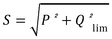
- the power supply method 1 comprises a calculation step 30 of an apparent power value in the main network.
- the notion of apparent power is a maximum power value available to operate an electrical network. It is the trigonometric sum of the active power and the reactive power.
- the calculation 30 of the apparent power value in the main network 110 is carried out from the voltage measured at the terminals of the at least one AC voltage source 111 and the current measured between the at least one AC voltage source 111 and the at least one electrical load 200.
- P represents the value of the active power in the main network 110
- Q represents the value of the reactive power in the main network 110.
- the apparent power is the trigonometric sum of two components, namely the active power and the reactive power.
- the regulation step 40 comprises a step 45 of observing the physical characteristics of the main network 110 and the auxiliary network 120. Indeed, it is necessary in order to subsequently perform a change of reference, to observe the position of the main network 110 relative to the auxiliary network 120.
- the power supply method 1 applies a phase-locked loop or PLL function which makes it possible to guarantee that the current and the voltage to the main network 110 connected to the auxiliary network 120 have the same frequency and the same phase.
- a transformation step 50 of the active power value P and the reactive power value Q according to a Park transformation This then involves making a change of reference in the Park vector reference. Therefore, in the Park vector reference, the active power value P and the reactive power value Q are written according to the following formulas: [0061] Where d and q represent the two axes of the Park vector frame. ⁇ ⁇ thus represents the value of the first voltage, namely the voltage across the at least one AC voltage source 111, along the d axis while ⁇ ⁇ represents the value of the first current, namely the electric current between the at least one AC voltage source 111 and the at least one electric load 200, along the d axis.
- ⁇ ⁇ thus represents the value of the first voltage, the at least one AC voltage source 111, along the q axis while ⁇ ⁇ represents the value of the first current, namely the electric current between the at least one AC voltage source 111 and the at least one electric load 200, along the q axis.
- the currents on the d axis of the main network 110 and the auxiliary network 120 are the image of the active powers supplied by these two networks and the currents on the q axis of the main network 110 and the auxiliary network 120 are the image of the reactive powers supplied by these two networks.
- This is followed by a decoupling step 60 of the transformed active power value and the transformed reactive power value.
- the power supply method 1 applies a phase-locked loop or PLL function to the transformed active power value and to the reactive power value. transformed.
- the PLL function used during step 45 may preferably be identical to the PLL function of the decoupling step 60.
- the power supply method 1 comprises a calculation step 70 of an active power value in the main network 110 and a calculation step 70' of a reactive power value in the main network 110, the active power and the reactive power being the components of the apparent power calculated during step 30.
- the transformed active power value and the reactive power value of transformed reactive power being decoupled and only carried by the currents ⁇ ⁇ and ⁇ ⁇
- the value of the active power P can be calculated during step 70 according to the following formula:
- the value of the reactive power Q can be calculated during step 70' according to the following formula: [0069] It should be noted that steps 70 and 70' can be performed simultaneously.
- the power supply method 1 also comprises a step of determining a reference active power value ⁇ ⁇ ⁇ ⁇ in the main network 110. [0071] The power supply method 1 also comprises a step of determining a reference reactive power value ⁇ ⁇ ⁇ ⁇ in the main network (110), [0072] After determining a reference active power value ⁇ ⁇ ⁇ ⁇ and a reference reactive power value ⁇ ⁇ ⁇ ⁇ , the power supply method comprises a step of regulating the active power P of the main network 110 by the reference active power value ⁇ ⁇ ⁇ ⁇ and the reactive power Q of the main network 110 by the reference reactive power value ⁇ ⁇ ⁇ ⁇ .
- the active power and the reactive power in the main network 110 is then regulated to a defined value so as to promote hybridization with the auxiliary network 120.
- additional active power and/or reactive power can be provided by the auxiliary network 120 during hybridization.
- the determination and regulation, during step 40, of the active power P and the reactive power Q can be carried out differently than stated above.
- a single-phase type PLL function is applied, such as for example a SOGI-OSG PLL function.
- ⁇ ⁇ ⁇ ⁇ ⁇ cos ( ⁇ )
- U represents the first voltage value measured in the main network 110, namely the voltage across the at least one AC voltage source 111
- I represents the first current value measured in the main network 110, namely the electric current between the at least one AC voltage source 111 and the at least one electric load 200
- ⁇ represents a phase shift.
- U represents the first voltage value measured in the main network 110, namely the voltage at the terminals of the at least one alternating voltage source 111
- I represents the first current value measured in the main network 110, namely the electric current between the at least one voltage source alternative 111 and the at least one electrical load 200
- ⁇ represents a phase shift.
- Other formulas or methods may be envisaged to allow the calculation of the value of the active power and the value of the reactive power in the main network 110.
- the determination of the active power P and the reactive power Q in the main network 110 may be envisaged in different ways, by first calculating an active power and reactive power value and then performing a Park transformation in a determined reference frame or inversely by first performing the transformation, imposing a current parameter and calculating the active power and reactive power values.
- the steps follow one another in the following manner: observation step 45, transformation step 50, decoupling step 60, calculation step 70 and calculation step 70'.
- calculation step 70, calculation step 70', observation step 45, transformation step 50 and decoupling step 60 it may be envisaged that the steps follow one another in the following manner: calculation step 70, calculation step 70', observation step 45, transformation step 50 and decoupling step 60.
- the power supply method 1 comprises a step 72 of estimating a necessary power value ⁇ ⁇ ⁇ ⁇ ⁇ ⁇ , a necessary active power value ⁇ ⁇ ⁇ ⁇ ⁇ and a necessary reactive power value ⁇ ⁇ ⁇ ⁇ ⁇ to the at least one electrical load 200.
- This necessary power value ⁇ ⁇ ⁇ ⁇ ⁇ ⁇ thus represents the power value to be supplied to the at least one electrical load 200 in order to allow its operation.
- This estimation of the necessary power ⁇ ⁇ ⁇ ⁇ ⁇ ⁇ can be known upstream due to the technical characteristics of the at least one electrical load 200 connected to the main network 110, and more precisely, the dimensional characteristics of the main network 110, or by means of the control module 123. According to this configuration, the control module 123 is also then connected to the at least one electrical load 200. More precisely, the necessary power value ⁇ ⁇ ⁇ ⁇ ⁇ ⁇ can be assimilated to a sum of a necessary active power value ⁇ ⁇ ⁇ ⁇ ⁇ being given that this power allows the operation of the at least one electrical load 200 and at a necessary reactive power value ⁇ ⁇ ⁇ ⁇ ⁇ .
- the necessary active power ⁇ ⁇ ⁇ ⁇ ⁇ ⁇ ⁇ and the necessary reactive power ⁇ ⁇ ⁇ ⁇ ⁇ ⁇ , consumed by the at least one load 200 are identifiable by the superposition theorem so that the necessary active power ⁇ ⁇ ⁇ ⁇ ⁇ ⁇ is equal to the set of active power values P in the electrical network and that the necessary reactive power ⁇ ⁇ ⁇ ⁇ ⁇ is equal to the set of reactive power values Q in the electrical network.
- the contribution of the powers in the main network 110 is written as follows: [0093]
- the estimation of the necessary active power ⁇ ⁇ ⁇ ⁇ ⁇ ⁇ , of the necessary reactive power ⁇ ⁇ ⁇ ⁇ ⁇ , and therefore of the necessary power ⁇ ⁇ ⁇ ⁇ ⁇ to the at least one electrical load 200 comes from the measurements of active power P and reactive power Q on the main network 110.
- a first configuration can be envisaged when the power to be supplied to the at least one electrical load 200, i.e. the necessary power ⁇ ⁇ ⁇ ⁇ ⁇ is less than or equal to the design limit power. of the alternating voltage source 111.
- the apparent power limit value of dimensioning ⁇ ⁇ ⁇ ⁇ of the main network 110 thus represents the maximum power value that the main network 110 can provide in the direction of the at least one electrical load 200. This apparent power limit value of dimensioning ⁇ ⁇ ⁇ ⁇ then depends on the dimensioning characteristics of the main network 110.
- This apparent power limit value of dimensioning ⁇ ⁇ ⁇ ⁇ of the main network 110 can be determined or estimated in parallel with the determination of the active power P and reactive power Q values in the main network 110 and the regulation 40 of these power values. [0097] Thus, if ⁇ ⁇ ⁇ ⁇ ⁇ ⁇ ⁇ ⁇ ⁇ ⁇ ⁇ ⁇ ⁇ then the power supply method 1 does not draw power from the auxiliary network 120 and no compensation is performed.
- the necessary power ⁇ ⁇ ⁇ ⁇ ⁇ ⁇ of the at least one electrical load 200 is less than an apparent power limit for sizing the main network, that is to say that the following equation is respected: [0099] Where, ⁇ ⁇ ⁇ ⁇ dimensioning of the main network 110 and ⁇ ⁇ ⁇ ⁇ represents the limit reactive power value for dimensioning of the main network 110. [0100] Then it is not necessary to add any power from the auxiliary network 120.
- the power supply method 1 then comprises a step 75 of injecting additional reactive power ⁇ ⁇ ⁇ ⁇ ⁇ and/or active power ⁇ ⁇ ⁇ ⁇ ⁇ of the auxiliary network 120 into the main network 110.
- the apparent power S of the main network, during the injection step 75 can be defined according to one of the following formulas: [0103]
- the definition of the apparent power of the main network 110 during the injection step 75 can be done in a predetermined manner.
- the definition of the apparent power during the injection step 75 is determined by the supply method 1. [0105] Indeed, as previously stated during step 72, it is possible to estimate the active power value required ⁇ ⁇ ⁇ ⁇ ⁇ for the at least one electrical load 200 and the reactive power value required ⁇ ⁇ ⁇ ⁇ ⁇ for the at least one electrical load 200.
- the active power value required ⁇ ⁇ ⁇ ⁇ ⁇ estimated during step 72 does not exceed a combined value between the active power value ⁇ of the main network 110 at the time and the limit reactive power value of the design ⁇ ⁇ ⁇ ⁇ of the main network 110, it is then possible to limit the apparent power of the main network 110 by injecting only additional reactive power ⁇ ⁇ ⁇ ⁇ ⁇ from the auxiliary network 120.
- This injection of additional reactive power ⁇ ⁇ ⁇ ⁇ ⁇ ⁇ from the auxiliary network 120 has the advantage of not having an impact on the electrical energy storage assembly 121.
- the power supply method 1 comprises a step 750 of injecting additional reactive power ⁇ ⁇ ⁇ ⁇ ⁇ ⁇ from the auxiliary network 120 into the main network 110.
- the power supply method 1 allows an injection, according to step 750 of a reactive power supplement ⁇ ⁇ ⁇ ⁇ ⁇ ⁇ from the auxiliary network 120 into the main network 110 and the apparent power in the main network 110, during the injection step 750, can be defined according to the following formula:
- ⁇ ⁇ ⁇ ⁇ represents the sum of the reactive power value Q initially present in the main network 110 and the value of the reactive power complement ⁇ ⁇ ⁇ ⁇ ⁇ ⁇ .
- This sum can also be interpreted as a reference reactive power value to meet the two conditions mentioned above, namely ⁇ ⁇ ⁇ ⁇ ⁇ ⁇ ⁇ and ⁇ ⁇ ⁇ ⁇ > ⁇ .
- the following conditions may be considered as a condition for the injection 750 of additional reactive power ⁇ ⁇ ⁇ ⁇ ⁇ from the auxiliary network 120 into the main network 110: ⁇ ⁇ ⁇ ⁇ ⁇ ⁇ ⁇ and ⁇ ⁇ ⁇ ⁇ ⁇ > ⁇ ⁇ ⁇ ⁇ [0109] Therefore, the condition on the active power value required ⁇ ⁇ ⁇ ⁇ ⁇ for the at least one electrical load 200 is simplified since the apparent power value S of the main network 110 is known. [0110] This second configuration translates into the case in which the apparent power of the at least one electrical load 200 is greater than a limit apparent power but the active power of the loads is less than this same apparent power.
- auxiliary network 120 Before compensation of the auxiliary network 120, it is possible to observe an excess of the power in the main network 110 compared to the apparent power limit of conceivable dimensioning. The aim is then to regulate the power of the network to reduce it to this limit power by injecting only reactive power from the auxiliary network 120 thus making it possible to limit the reactive power of the aircraft electrical system 300. [0111] Otherwise, a third operating configuration can be envisaged. Indeed, if the power to be supplied to the at least one electrical load 200, i.e.
- the power supply method 1 allows an injection of a reactive power supplement ⁇ ⁇ ⁇ ⁇ ⁇ ⁇ and an active power supplement ⁇ ⁇ ⁇ ⁇ ⁇ ⁇ .
- the supply method 1 comprises a step 752 of injecting a reactive power supplement ⁇ ⁇ ⁇ ⁇ ⁇ from the auxiliary network 120 into the main network 110 and a supplement of active power ⁇ ⁇ ⁇ ⁇ ⁇ from the auxiliary network 120 into the main network 110.
- the power supply method 1 allows an injection, according to step 752, of a reactive power supplement ⁇ ⁇ ⁇ ⁇ ⁇ from the auxiliary network 120 into the main network 110 and of an active power supplement ⁇ ⁇ ⁇ ⁇ ⁇ from the auxiliary network 120 into the main network 110 the apparent power in the main network 110.
- the apparent power can be defined according to the following formula: Where ⁇ ⁇ ⁇ ⁇ ⁇ represents the sum of the reactive power value Q initially present in the main network 110 and the value of the reactive power complement ⁇ ⁇ ⁇ ⁇ ⁇ ⁇ and ⁇ ⁇ ⁇ ⁇ represents the sum of the active power value P initially present in the main network 110 and the value of the active power complement ⁇ ⁇ ⁇ ⁇ ⁇ ⁇ .
- the sum ⁇ ⁇ ⁇ ⁇ can also be interpreted as a reference reactive power value while the sum ⁇ ⁇ ⁇ ⁇ can also be interpreted as a reference active power value to meet the two conditions mentioned above, namely ⁇ ⁇ ⁇ ⁇ ⁇ > ⁇ 2 ⁇ ⁇ ⁇ + ⁇ 2 ⁇ ⁇ ⁇ and ⁇ ⁇ ⁇ ⁇ ⁇ > ⁇ .
- the following conditions may be considered as a condition for the injection 752 of additional reactive power ⁇ ⁇ ⁇ ⁇ ⁇ from the auxiliary network 120 and additional active power ⁇ ⁇ ⁇ ⁇ into the main network 110: ⁇ ⁇ ⁇ ⁇ > ⁇ ⁇ ⁇ ⁇ ⁇ and ⁇ ⁇ ⁇ ⁇ ⁇ > ⁇ ⁇ ⁇ ⁇ [0115] Therefore, the condition on the active power value required ⁇ ⁇ ⁇ ⁇ ⁇ for the at least one electrical load 200 is simplified since the apparent power value limit for dimensioning ⁇ ⁇ ⁇ ⁇ of the main network 110 is known.
- This third configuration translates as the case in which the necessary apparent power of the at least one electrical load 200 is greater than a limit apparent power of the main network 110 and the necessary active power of the at least one electrical load 200 is also greater than this same limit apparent power of the main network 110.
- the auxiliary network 120 it is possible to observe an excess of the power of the main network 110 with respect to the power limit accepted in the main network 110, characterized by the limit power value ⁇ ⁇ ⁇ ⁇ .
- PFC power factor correction
- additional power must be provided from the auxiliary network 120 to the main network. And therefore if ⁇ ⁇ ⁇ ⁇ ⁇ > ⁇ ⁇ ⁇ ⁇ then there is a hybridization between the auxiliary network 120 and the main network 110. The nature of the additional power is then determined according to the second condition linked to the necessary active power value ⁇ ⁇ ⁇ ⁇ ⁇ .
- the power supply method has the advantage of allowing optimized management from one configuration to another configuration with respect to the three configurations mentioned above as a function of the apparent power S available in the main network 110, of the apparent limit power ⁇ ⁇ ⁇ ⁇ linked to the dimensioning of the main network 110 and of the power required ⁇ ⁇ ⁇ ⁇ ⁇ for the at least one electrical load 200.
- the power supply method 1 makes it possible to target the second configuration or the third configuration with respect to the active power value required ⁇ ⁇ ⁇ ⁇ ⁇ ⁇ .
- active load shedding i.e.
- Figure 3 thus represents a device 100 for supplying electrical energy to at least one electrical load 200 in an aircraft electrical system according to the supply method 1.
- the supply device 100 is composed in particular of the main network 110 and the auxiliary network 120.
- the main network 110 comprises the at least one source of alternating voltage 111 by mechanical tapping on the drive system 112 connected to the current generation control unit 113.
- the at least one source of alternating voltage 111 is connected to the at least one electrical load 200.
- the auxiliary network 120 comprises: - The at least one electrical energy storage assembly 121 configured to supply direct current to the at least one electrical load 200, - the converter 122, arranged between the electrical energy storage assembly 121 and the at least one electrical load 200 and configured to convert the direct current delivered by the at least one electrical energy storage assembly 121 into an alternating current, - and the converter control module 123 configured to measure the voltage across the at least one alternating voltage source 111 and the current between the at least one alternating voltage source 111 and the at least one electrical load 200.
- the converter control module 123 can also measure the electrical voltage across the converter 122 and the current between the converter 122 and the at least one electrical load 200.
- the auxiliary network 120 can also comprise a filter 124 arranged between the converter 122 and the at least one electrical load 200 configured to eliminate the voltage harmonics linked to the chopping of the converter 122 and to generate a sinusoidal three-phase voltage within the auxiliary network 120.
- the auxiliary network 120 may comprise a hybridization contactor 126 between the filter 124 and the main network 110 making it possible to isolate or couple the secondary network 120 to the main network 110, and thus to supply the at least one electrical load 200 using the auxiliary network 120.
- the at least one electrical energy storage assembly 121 is a battery.
- the at least one electrical storage assembly is a DC voltage source.
- the main network 110 and the auxiliary network 120 are three-phase networks, as shown in FIG. 3.
- the main network 110 and the auxiliary network 120 can also be AC single-phase networks or even multi-phase networks. Therefore, the phase-locked loop function or PLL to the transformed active power value and to the reactive power value is adapted according to the number of phases of the network.
- main 110 and the auxiliary network 120 are three-phase networks, as shown in FIG. 3.
- the main network 110 and the auxiliary network 120 can also be AC single-phase networks or even multi-phase networks. Therefore, the phase-locked loop function or PLL to the transformed active power value and to the reactive power value is adapted according to the number of phases of the network.
- main 110 and the auxiliary network 120 are three-phase networks, as shown in FIG. 3.
- the main network 110 and the auxiliary network 120 can also be AC single-phase networks or even multi-phase networks. Therefore, the phase-locked loop function or PLL to the transformed active power value and to the reactive power value is adapted according to the number of phases of the network
- a PLL function of the SOGI-OSG type can be envisaged in a situation of main network 110 and auxiliary network 120 single-phase alternating in order to allow a transformation in a two-phase vector reference frame.
- the at least one alternating voltage source 111 is an alternator or a three-stage machine commonly used for the electrical generation of the aircraft network, the output voltage of which is regulated to a constant value independently of the speed of the rotating shaft.
- any regulated voltage source such as a three-phase voltage inverter, a Park group can be envisaged.
- FIGS. 4A and 4B schematically represent the linearization strategies of the three power supply configurations of the power supply method 1.
- linearization strategies advantageously make it possible to calculate power references making it possible to compensate for the lack of active power or reactive power in the main network 110.
- the different linearization strategies can thus be defined according to two levels: a first level during which reference powers are determined, as shown in FIG. 4A, and a second level during which a regulation of the current in the Park reference frame is determined, as shown in FIG. 4B.
- these linearization strategies allow a decoupling of control of the active power value P and the value of reactive power Q of the main network 110 on the two axes of the vector frame after Park transform during step 50. As stated previously, two axes are then identified according to the Park vector frame, namely the d axis and the q axis.
- Controlling the active power value P of the main network 110 provides information on the current directed on the d axis of the Park vector frame that the converter 122 must supply.
- Each linearization strategy of the different configurations of the power supply method 1, namely the first configuration, the second configuration and the third configuration, thus makes it possible to define the reference active power value ⁇ ⁇ ⁇ ⁇ and the reference reactive power value ⁇ ⁇ ⁇ ⁇ from so as to comply with the conditions stated previously, as shown in FIG. 4A.
- the difference 1001 between the apparent power value ⁇ ⁇ ⁇ ⁇ limit of the main network 110 and the necessary active power value ⁇ ⁇ ⁇ ⁇ ⁇ is negative and saturation makes it possible to impose a positive active current reference, by changing the sign of the active current for example.
- the reactive power value Q of the main network is regulated to 0 and the active power value P is regulated to the apparent power value ⁇ ⁇ ⁇ ⁇ limit of the main network so as to force the auxiliary network 120 to compensate all the reactive power by means of the reactive power supplement ⁇ ⁇ ⁇ ⁇ ⁇ and provide the active power supplement ⁇ ⁇ ⁇ ⁇ necessary to the main network 110.
- the saturation makes it possible to generate an active current reference in the inverter only when the difference 1001 between the apparent power value ⁇ ⁇ ⁇ ⁇ limit of the main network 110 and the active power value necessary ⁇ ⁇ ⁇ ⁇ ⁇ is negative, that is to say when the power supply method 1 is in the third configuration. Otherwise, when the power supply method 1 is in the first configuration or in the second configuration, the reference is set to 0. [0137]
- the control of the reactive power value Q of the main network 110 provides information on the current directed on the q axis in the Park frame that the converter 122 must supply according to the configuration of the power supply method 1.
- the reference reactive power value ⁇ ⁇ ⁇ ⁇ corresponds, for its part, to the reference reactive power to allow the main network 110 to increase its available power to an apparent power value ⁇ ⁇ ⁇ ⁇ limit knowing the active power, in the second configuration. [0139] However, in the first power supply configuration of the power supply method 1, this power exceeds the reactive power value Q in the main network 110 and the saturation prevents any action of the converter 122. [0140] And, according to the third power supply configuration of the power supply method 1, it is necessary to linearize the calculation of the reference reactive power value during the transient time of the regulation of the active power value. In established steady state, the reference reactive power is then zero.
- This first strategy of the first configuration then translates into an absence of injection of compensation from the auxiliary network 120 and therefore a decoupling of the auxiliary network 120 and the main network 110 by the action of the hybridization contactor 126.
- the first linearization strategy therefore makes it possible to impose an operation according to the first compensation configuration, by imposing ⁇ ⁇ ⁇ ⁇ ⁇ ⁇ ⁇ ⁇ ⁇ ⁇ ⁇ ⁇ ⁇ ⁇ ⁇ ⁇ .
- the second linearization strategy according to the second power supply configuration makes it possible to impose a zero value on a current in the Park frame.
- the objective is then to regulate the power of the aircraft electrical system 300 to lower it by injecting only reactive power, thus making it possible to limit the reactive power of the aircraft electrical system 300.
- the second linearization strategy thus allows operation according to the second compensation configuration by imposing ⁇ ⁇ ⁇ ⁇ ⁇ ⁇ ⁇ ⁇ ⁇ ⁇ ⁇ ⁇ ⁇ ⁇ ⁇ ⁇ .
- the necessary apparent power of the at least one electrical load 200 is greater than a limit apparent power ⁇ ⁇ ⁇ ⁇ and the active power necessary of the at least one electrical load 200 is also greater than this same apparent power limit ⁇ ⁇ ⁇ ⁇ ⁇ .
- Each of the linearization strategies namely the first linearization strategy, the second linearization strategy and the third linearization strategy, making it possible to determine the active power references and reactive power, can be implemented according to a functional diagram shown in Figure 4A.
- two nested loops in cascade make it possible to implement in order to control the converter 122: -
- a first external regulation loop 1010 which allows the control of the powers of the main network 110, that is to say the control of the active powers P and reactive powers Q of the network in order to limit the apparent power S.
- the external regulation loop 1010 provides current references at the output of the auxiliary network 120.
- the first external regulation loop 1010 imposes a current reference on the d axis and the q axis according to the Park reference at the level of the auxiliary network 120.
- the first internal regulation loop 1010 adds compensation terms linked to the decoupling of the active power and reactive power values and to the output voltage.
- a second internal regulation loop 1020 which allows the control of the currents at the output of the converter 122. More precisely, the second internal regulation loop 1020 comprises a first current regulator 1021 on the first axis of the Park frame, the d axis for example, and a second current regulator 1022 on the second axis of the Park frame, the q axis.
- FIG. 5 represents a graph of the energy compensation observed via the power supply method 1 during a given period. According to the example represented by this graph, the apparent power ⁇ ⁇ ⁇ ⁇ limit of the main network 110 is 40 kVA.
- the supply method 1 remains in the first configuration.
- the power demand i.e. the value of the necessary power ⁇ ⁇ ⁇ ⁇ ⁇ ⁇ to the at least one useful load 200 exceeds the fixed apparent power limit S of the at least one AC voltage source 111 but the necessary active power value ⁇ ⁇ ⁇ ⁇ ⁇ ⁇ remains lower than or equal to the fixed apparent power limit S of the at least one AC voltage source 111, as illustrated in the intervals [0.5; 1.6] and [1.9; 2.5] in the graph of FIG.
- the power supply method 1 then switches to an energy compensation configuration, namely the second configuration or the third energy compensation configuration in order to provide compensation in reactive power and possibly in active power from the auxiliary network 120. Consequently, an additional supply of reactive power can be observed from the auxiliary network 120 making it possible to extend, transiently, the apparent power value S beyond its base value.
- the converter 122 provides power compensation by regulation as indicated in FIG. 4B. This compensation not being instantaneous, the main network 110 observes a power transient whose value depends on the load impact, here 45kVA or 50kVA. This compensation is also performed promptly so as to avoid any unwanted heating of the aircraft electrical system 300.
- the auxiliary network 120 does not provide any power and the power of the main network 110 provides all the power to the at least one electrical load 200, highlighting the first energy compensation configuration. This is the case over the intervals [0; 0.5], [1.6; 1.9] and [2.4; 2.7] on the graph in FIG. 5.
- the power supply method 1 is in the second energy compensation configuration at the intervals [0.5; 0.8], [1.3; 1.6] and in the third energy compensation configuration at the intervals [0.8; 1.3] and [1.9; 2.4].
- the power supply method 1 also allows for reverse switching, i.e. switching from the third power supply configuration to the second power supply configuration as shown at 1.3 seconds in the graph of FIG. 5, and switching from the second configuration to the first configuration when no compensation is required, as shown at 1.6 seconds in the graph of FIG. 5.
- the power supply method 1 also allows for switching from the first configuration to the third configuration and vice versa during large variations in the active power demand at the at least one electrical load 200, as shown at the interval [1.9; 2.4] on the graph of FIG. 5.
- FIG. 6 illustrates the different compensation configurations in which the aircraft electrical system 300 can be located depending on the energy requirement of the at least one electrical load 200, and more precisely the application of the second configuration and the third energy compensation configuration.
- the active power required ⁇ ⁇ ⁇ ⁇ ⁇ of the at least one electrical load 200 does not exceed the apparent power limit ⁇ ⁇ ⁇ ⁇ .
- the auxiliary network 120 compensates only a portion of the reactive power of the main network 110, as shown in the intervals [0.5; 0.8] and [1.4; 1.6] of the graph of figure 6. [0169]
- the active power required ⁇ ⁇ ⁇ ⁇ ⁇ of the at least one electrical load 200 exceeds the apparent power ⁇ ⁇ ⁇ ⁇ limit.
- the power supply method 1, and the power supply device which applies the power supply method 1, thus have the advantage of making it possible to limit the powers of the main network 110, therefore seen by the electrical machine. It is then possible to size the electrical machines that are sources of alternating current such as alternators as precisely as possible to maintain average usage powers since the auxiliary network 120 makes it possible to cope with the occasional overloads subjected to the main network 110.
- the solution is not intrusive and is completely dissociated from the method for controlling the main network 110.
- the linearization strategy 1000 makes it possible to reduce the energy requirement of the HVDC electrical energy storage element 121 and therefore to reduce its mass on networks comprising inductive loads.
Landscapes
- Engineering & Computer Science (AREA)
- Power Engineering (AREA)
- Supply And Distribution Of Alternating Current (AREA)
Abstract
Description





Claims

Priority Applications (2)
| Application Number | Priority Date | Filing Date | Title |
|---|---|---|---|
| EP24733618.3A EP4728610A1 (fr) | 2023-06-16 | 2024-06-17 | Procede et dispositif de controle des puissances d'un reseau alternatif triphase par hybridation parallele avec un onduleur pilote et une source dc |
| CN202480040219.6A CN121532921A (zh) | 2023-06-16 | 2024-06-17 | 用于通过与控制逆变器和dc源并联混合来控制三相ac电网的功率的方法和设备 |
Applications Claiming Priority (2)
| Application Number | Priority Date | Filing Date | Title |
|---|---|---|---|
| FR2306179A FR3150055A1 (fr) | 2023-06-16 | 2023-06-16 | Procédé et dispositif de contrôle des puissances d’un réseau alternatif triphasé par hybridation parallèle avec un onduleur piloté et une source DC |
| FRFR2306179 | 2023-06-16 |
Publications (1)
| Publication Number | Publication Date |
|---|---|
| WO2024256728A1 true WO2024256728A1 (fr) | 2024-12-19 |
Family
ID=87801035
Family Applications (1)
| Application Number | Title | Priority Date | Filing Date |
|---|---|---|---|
| PCT/EP2024/066847 Ceased WO2024256728A1 (fr) | 2023-06-16 | 2024-06-17 | Procede et dispositif de controle des puissances d'un reseau alternatif triphase par hybridation parallele avec un onduleur pilote et une source dc |
Country Status (4)
| Country | Link |
|---|---|
| EP (1) | EP4728610A1 (fr) |
| CN (1) | CN121532921A (fr) |
| FR (1) | FR3150055A1 (fr) |
| WO (1) | WO2024256728A1 (fr) |
Citations (4)
| Publication number | Priority date | Publication date | Assignee | Title |
|---|---|---|---|---|
| US20110210606A1 (en) * | 2010-01-28 | 2011-09-01 | Airbus Operations Gmbh | Method and device for providing an electrical system alternating voltage in an aircraft |
| WO2018051003A1 (fr) | 2016-09-13 | 2018-03-22 | Safran | Procede et systeme d'alimentation d'une charge electrique dans un aeronef |
| CN107925245A (zh) * | 2015-07-09 | 2018-04-17 | 利莱森玛电机公司 | 对充电冲击、负载脱落和谐波进行改善处理的发电系统 |
| EP4087079A1 (fr) * | 2021-05-07 | 2022-11-09 | Thales | Procédé de gestion de fonctionnement d'un système d'alimentation électrique d'aéronef comprenant au moins un ensemble de stockage d'énergie électrique |
-
2023
- 2023-06-16 FR FR2306179A patent/FR3150055A1/fr active Pending
-
2024
- 2024-06-17 CN CN202480040219.6A patent/CN121532921A/zh active Pending
- 2024-06-17 WO PCT/EP2024/066847 patent/WO2024256728A1/fr not_active Ceased
- 2024-06-17 EP EP24733618.3A patent/EP4728610A1/fr active Pending
Patent Citations (4)
| Publication number | Priority date | Publication date | Assignee | Title |
|---|---|---|---|---|
| US20110210606A1 (en) * | 2010-01-28 | 2011-09-01 | Airbus Operations Gmbh | Method and device for providing an electrical system alternating voltage in an aircraft |
| CN107925245A (zh) * | 2015-07-09 | 2018-04-17 | 利莱森玛电机公司 | 对充电冲击、负载脱落和谐波进行改善处理的发电系统 |
| WO2018051003A1 (fr) | 2016-09-13 | 2018-03-22 | Safran | Procede et systeme d'alimentation d'une charge electrique dans un aeronef |
| EP4087079A1 (fr) * | 2021-05-07 | 2022-11-09 | Thales | Procédé de gestion de fonctionnement d'un système d'alimentation électrique d'aéronef comprenant au moins un ensemble de stockage d'énergie électrique |
Also Published As
| Publication number | Publication date |
|---|---|
| FR3150055A1 (fr) | 2024-12-20 |
| CN121532921A (zh) | 2026-02-13 |
| EP4728610A1 (fr) | 2026-04-22 |
Similar Documents
| Publication | Publication Date | Title |
|---|---|---|
| US7715950B2 (en) | Non-inverter based distributed energy resource for use in a dynamic distribution system | |
| EP2221936B1 (fr) | Système et procédé de contrôle d'un système de génération d'alimentation raccordé à une grille | |
| EP2853693B1 (fr) | Procédé et module de protection contre les pics de couple entre un moteur et une machine électrique | |
| EP1788697A1 (fr) | Dispositif de correction de facteur de puissance pour variateur de vitesse | |
| EP3729598B1 (fr) | Procédé et système de régulation d'un convertisseur électrique pour stabilisation autonome de fréquence avec des transitoires de charge dans un micro-réseau comprenant un groupe électrogène diesel | |
| EP3365970B1 (fr) | Démarreur-générateur de turbomachine a machine électrique asynchrone multi-enroulements | |
| FR3038796A1 (fr) | Systeme de generation d'energie a traitement ameliore des impacts a charge, des delestages et des harmoniques | |
| EP4728610A1 (fr) | Procede et dispositif de controle des puissances d'un reseau alternatif triphase par hybridation parallele avec un onduleur pilote et une source dc | |
| EP3847734A1 (fr) | Procédé de commande d'un équipement d'alimentation électrique d'un système électrique | |
| FR2894087A1 (fr) | Methode et dispositif de regulation pour un dispositif de production decentralisee d'energie, et installation comportant au moins deux dispositifs de production dotes dudit dispositif de regulation | |
| Mishra et al. | Wind energy generation system using wound rotor induction machine | |
| EP2158657B1 (fr) | Systeme et procede de controle d'un tcsc dans un reseau de transport d'energie electrique notamment par une approche modes glissants | |
| WO2019229390A1 (fr) | Système de synchronisation de sources d'énergie couplées d'un aéronef | |
| US20250119035A1 (en) | Variable-speed synchronous generator-motor device | |
| WO2024126933A1 (fr) | Transfert de puissance entre un corps haute pression et un corps basse pression d'une turbomachine d'un aéronef | |
| EP3827512B1 (fr) | Syteme de generation d'energie electrique et procede de regulation d'un systeme de generation d'energie electrique pour un reseau de distribution electrique d'un aeronef | |
| EP4047813B1 (fr) | Module de régulation pour une machine électrique tournante | |
| FR3150666A1 (fr) | Procédé de contrôle d’une machine électrique en mode moteur par hybridation parallèle d’un réseau électrique auxiliaire. | |
| FR2779583A1 (fr) | Systeme antipollution pour reseau electrique | |
| WO2022106782A1 (fr) | Dispositif et procédé de contrôle de la tension des microréseaux | |
| Nguyen | Analysis and control of the stability of power systems with a high penetration of renewable energy | |
| FR3161517A1 (fr) | Convertisseur triphasé, aéronef et procédé de commande associés | |
| WO2025210174A1 (fr) | Procédé et dispositif de gestion de puissance pour une machine électrique | |
| FR3164850A1 (fr) | Contrôle d’une puissance injectée par un module de production d’énergie renouvelable dans un micro-réseau électrique par pilotage en fréquence d’un module de génération thermique d’énergie électrique | |
| Puchalapalli et al. | A novel control scheme for wind driven DFIG interfaced with utility grid |
Legal Events
| Date | Code | Title | Description |
|---|---|---|---|
| 121 | Ep: the epo has been informed by wipo that ep was designated in this application |
Ref document number: 24733618 Country of ref document: EP Kind code of ref document: A1 |
|
| WWE | Wipo information: entry into national phase |
Ref document number: 2024733618 Country of ref document: EP |
|
| NENP | Non-entry into the national phase |
Ref country code: DE |
|
| ENP | Entry into the national phase |
Ref document number: 2024733618 Country of ref document: EP Effective date: 20260116 |
|
| ENP | Entry into the national phase |
Ref document number: 2024733618 Country of ref document: EP Effective date: 20260116 |
|
| ENP | Entry into the national phase |
Ref document number: 2024733618 Country of ref document: EP Effective date: 20260116 |
|
| ENP | Entry into the national phase |
Ref document number: 2024733618 Country of ref document: EP Effective date: 20260116 |
|
| WWP | Wipo information: published in national office |
Ref document number: 2024733618 Country of ref document: EP |