WO2024257150A1 - Impeller, blower, and air conditioner - Google Patents
Impeller, blower, and air conditioner Download PDFInfo
- Publication number
- WO2024257150A1 WO2024257150A1 PCT/JP2023/021682 JP2023021682W WO2024257150A1 WO 2024257150 A1 WO2024257150 A1 WO 2024257150A1 JP 2023021682 W JP2023021682 W JP 2023021682W WO 2024257150 A1 WO2024257150 A1 WO 2024257150A1
- Authority
- WO
- WIPO (PCT)
- Prior art keywords
- chord
- impeller
- blade
- section
- camber
- Prior art date
- Legal status (The legal status is an assumption and is not a legal conclusion. Google has not performed a legal analysis and makes no representation as to the accuracy of the status listed.)
- Ceased
Links
Images





Classifications
-
- F—MECHANICAL ENGINEERING; LIGHTING; HEATING; WEAPONS; BLASTING
- F04—POSITIVE - DISPLACEMENT MACHINES FOR LIQUIDS; PUMPS FOR LIQUIDS OR ELASTIC FLUIDS
- F04D—NON-POSITIVE-DISPLACEMENT PUMPS
- F04D29/00—Details, component parts, or accessories
- F04D29/26—Rotors specially for elastic fluids
- F04D29/32—Rotors specially for elastic fluids for axial flow pumps
- F04D29/38—Blades
- F04D29/384—Blades characterised by form
-
- F—MECHANICAL ENGINEERING; LIGHTING; HEATING; WEAPONS; BLASTING
- F04—POSITIVE - DISPLACEMENT MACHINES FOR LIQUIDS; PUMPS FOR LIQUIDS OR ELASTIC FLUIDS
- F04D—NON-POSITIVE-DISPLACEMENT PUMPS
- F04D17/00—Radial-flow pumps, e.g. centrifugal pumps; Helico-centrifugal pumps
- F04D17/02—Radial-flow pumps, e.g. centrifugal pumps; Helico-centrifugal pumps having non-centrifugal stages, e.g. centripetal
- F04D17/04—Radial-flow pumps, e.g. centrifugal pumps; Helico-centrifugal pumps having non-centrifugal stages, e.g. centripetal of transverse-flow type
-
- F—MECHANICAL ENGINEERING; LIGHTING; HEATING; WEAPONS; BLASTING
- F04—POSITIVE - DISPLACEMENT MACHINES FOR LIQUIDS; PUMPS FOR LIQUIDS OR ELASTIC FLUIDS
- F04D—NON-POSITIVE-DISPLACEMENT PUMPS
- F04D29/00—Details, component parts, or accessories
- F04D29/26—Rotors specially for elastic fluids
- F04D29/28—Rotors specially for elastic fluids for centrifugal or helico-centrifugal pumps for radial-flow or helico-centrifugal pumps
- F04D29/281—Rotors specially for elastic fluids for centrifugal or helico-centrifugal pumps for radial-flow or helico-centrifugal pumps for fans or blowers
-
- F—MECHANICAL ENGINEERING; LIGHTING; HEATING; WEAPONS; BLASTING
- F04—POSITIVE - DISPLACEMENT MACHINES FOR LIQUIDS; PUMPS FOR LIQUIDS OR ELASTIC FLUIDS
- F04D—NON-POSITIVE-DISPLACEMENT PUMPS
- F04D29/00—Details, component parts, or accessories
- F04D29/26—Rotors specially for elastic fluids
- F04D29/28—Rotors specially for elastic fluids for centrifugal or helico-centrifugal pumps for radial-flow or helico-centrifugal pumps
- F04D29/281—Rotors specially for elastic fluids for centrifugal or helico-centrifugal pumps for radial-flow or helico-centrifugal pumps for fans or blowers
- F04D29/282—Rotors specially for elastic fluids for centrifugal or helico-centrifugal pumps for radial-flow or helico-centrifugal pumps for fans or blowers the leading edge of each vane being substantially parallel to the rotation axis
- F04D29/283—Rotors specially for elastic fluids for centrifugal or helico-centrifugal pumps for radial-flow or helico-centrifugal pumps for fans or blowers the leading edge of each vane being substantially parallel to the rotation axis rotors of the squirrel-cage type
-
- F—MECHANICAL ENGINEERING; LIGHTING; HEATING; WEAPONS; BLASTING
- F04—POSITIVE - DISPLACEMENT MACHINES FOR LIQUIDS; PUMPS FOR LIQUIDS OR ELASTIC FLUIDS
- F04D—NON-POSITIVE-DISPLACEMENT PUMPS
- F04D29/00—Details, component parts, or accessories
- F04D29/26—Rotors specially for elastic fluids
- F04D29/28—Rotors specially for elastic fluids for centrifugal or helico-centrifugal pumps for radial-flow or helico-centrifugal pumps
- F04D29/30—Vanes
-
- F—MECHANICAL ENGINEERING; LIGHTING; HEATING; WEAPONS; BLASTING
- F04—POSITIVE - DISPLACEMENT MACHINES FOR LIQUIDS; PUMPS FOR LIQUIDS OR ELASTIC FLUIDS
- F04D—NON-POSITIVE-DISPLACEMENT PUMPS
- F04D29/00—Details, component parts, or accessories
- F04D29/26—Rotors specially for elastic fluids
- F04D29/32—Rotors specially for elastic fluids for axial flow pumps
- F04D29/325—Rotors specially for elastic fluids for axial flow pumps for axial flow fans
- F04D29/326—Rotors specially for elastic fluids for axial flow pumps for axial flow fans comprising a rotating shroud
-
- F—MECHANICAL ENGINEERING; LIGHTING; HEATING; WEAPONS; BLASTING
- F04—POSITIVE - DISPLACEMENT MACHINES FOR LIQUIDS; PUMPS FOR LIQUIDS OR ELASTIC FLUIDS
- F04D—NON-POSITIVE-DISPLACEMENT PUMPS
- F04D29/00—Details, component parts, or accessories
- F04D29/26—Rotors specially for elastic fluids
- F04D29/32—Rotors specially for elastic fluids for axial flow pumps
- F04D29/38—Blades
-
- F—MECHANICAL ENGINEERING; LIGHTING; HEATING; WEAPONS; BLASTING
- F04—POSITIVE - DISPLACEMENT MACHINES FOR LIQUIDS; PUMPS FOR LIQUIDS OR ELASTIC FLUIDS
- F04D—NON-POSITIVE-DISPLACEMENT PUMPS
- F04D29/00—Details, component parts, or accessories
- F04D29/26—Rotors specially for elastic fluids
- F04D29/32—Rotors specially for elastic fluids for axial flow pumps
- F04D29/38—Blades
- F04D29/384—Blades characterised by form
- F04D29/386—Skewed blades
Definitions
- This disclosure relates to impellers, blowers, and air conditioners.
- impellers in which multiple blades are arranged radially (see, for example, Patent Document 1).
- the center in the circumferential direction of the root of the blade is R1
- the center in the circumferential direction of the outer periphery of the blade is R2
- the center of rotation of the blade is O.
- the angle between the line connecting O and R1 and the line connecting O and R2 is 18 to 22 degrees
- the line P connecting R1 and R2 is inclined at an angle of 22 to 27 degrees toward the suction side with respect to a plane perpendicular to the rotation axis passing through R1.
- the impeller of Patent Document 1 has an inflection point within the blade cross section in the shape of the cross section in the circumferential direction of the blade.
- the impeller of Patent Document 1 has a convex shape with a convex discharge side between the leading edge of the blade in the rotation direction and the inflection point, and a concave shape with a concave discharge side between the inflection point and the trailing edge of the blade in the rotation direction.
- the impeller in Patent Document 1 has these convex and concave shapes formed over the entire length of the blades, from the base to the outer periphery.
- the efficiency of an impeller is improved by suppressing separation that occurs on the blade surface.
- the impeller of Patent Document 1 has blades formed in the above-mentioned configuration, and is therefore said to be able to reduce noise caused by the rotation of the blades when the impeller is rotating.
- the impeller of Patent Document 1 has a convex shape on the leading edge side and a concave shape on the trailing edge side over the entire length from the base of the blade to the outer periphery, so there is a risk that separation of the airflow will occur due to the convex shape on the outer periphery side, where the airflow is faster than on the inner periphery side of the impeller, resulting in a deterioration of the air blowing performance.
- the present disclosure is intended to solve the problems described above, and aims to provide an impeller, a blower, and an air conditioner that suppress airflow separation and improve blowing performance.
- the impeller according to the present disclosure comprises a boss portion provided on a rotating shaft and a plurality of blades provided on the outer periphery of the boss portion, and each of the plurality of blades has a leading edge portion which is the edge portion on the forward side in the direction of rotation, a trailing edge portion which is the edge portion on the rearward side in the direction of rotation, an outer peripheral end portion which is the edge portion on the outer periphery, and an inner peripheral edge portion which is the edge portion on the inner periphery.
- each imaginary cross section of the multiple blades corresponding to the cylindrical portion is defined as a chord direction cross section
- a straight line connecting the leading edge portion and the trailing edge portion in the chord direction cross section is defined as a blade chord
- the center line of the blade cross section is defined as a camber line
- the camber line in a direction perpendicular to the blade chord and the blades in the chord direction cross section are defined as a camber line.
- the camber midpoint the position on the camber line where the distance from the leading edge and the trailing edge is equal is defined as the camber midpoint
- the point on the camber line where the camber height is maximum is defined as the maximum extreme point
- the camber line has at least one inflection point between the leading edge and the maximum extreme point, and in a chord direction cross section at a position closer to the outer periphery than the inner periphery of the blade, the maximum extreme point is located on the leading edge side of the camber midpoint and on the air intake side of the chord.
- the blower according to the present disclosure includes a casing having a bellmouth, and an impeller of the above configuration housed inside the casing, and when the extension length of the casing in the axial direction of the rotating shaft is defined as length Hb and the coefficient ⁇ is defined as 0 ⁇ 0.5, the impeller is disposed in a region inside an imaginary plane located a length ⁇ Hb away from the casing on the air suction side and on the air blowing side in the axial direction of the rotating shaft.
- the air conditioner disclosed herein includes an impeller having the above-described configuration and a heat exchanger that exchanges heat between the air supplied by the impeller and the refrigerant circulating inside.
- the impeller, and the impeller of the blower and air conditioner are configured as follows.
- the maximum extreme point is located on the trailing edge side of the camber midpoint and on the air intake side of the blade chord.
- the camber line also has at least one inflection point between the leading edge and the maximum extreme point.
- the maximum extreme point is located on the leading edge side of the camber midpoint and on the air intake side of the blade chord.
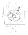
- FIG. 1 is a perspective view showing a configuration of an impeller and a blower including the impeller according to a first embodiment of the present invention
- 1 is a conceptual diagram for explaining the basic configuration of an impeller according to a first embodiment, showing the impeller projected onto a plane perpendicular to the rotation axis.
- FIG. 3 is a conceptual diagram showing a cross section taken along line III-III in FIG. 2 as viewed in the direction of the arrows.
- 2 is a conceptual diagram showing an example of a cross section in the chord direction of a blade of an impeller according to embodiment 1.
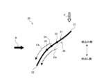
- FIG. 4 is a conceptual diagram showing a chord and a camber line in a section in the chord direction taken along line IV-IV in FIG. 2.
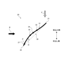
- FIG. 3 is a conceptual diagram showing the chord and camber lines in a section in the chord direction taken along the line VV in FIG. 2.
- FIG. 4 is a conceptual diagram showing the chord and camber lines in a cross section in the chord direction taken along line IV-IV in FIG. 2 for explaining the operation of the impeller and the flow of air currents according to the first embodiment.
- 3 is a conceptual diagram showing the chord and camber lines in a cross section in the chord direction taken along line VV in FIG. 2 for explaining the operation of the impeller and the flow of air currents according to the first embodiment.
- FIG. FIG. 4 is a conceptual diagram showing an impeller according to a second embodiment, illustrating a chord and a camber line in a cross section in the chord direction taken along line IV-IV in FIG.
- FIG. 3 is a conceptual diagram showing an impeller according to a second embodiment, illustrating the chord and camber lines in a cross section in the chord direction taken along line VV in FIG. 2.
- 13 is a graph showing the relationship between the flow coefficient and the fan efficiency of the impeller according to the second embodiment and an impeller of the prior art.
- 13 is a graph showing the relationship between the flow coefficient and the pressure coefficient of the impeller according to the second embodiment and an impeller of the prior art.
- FIG. 4 is a conceptual diagram showing an impeller according to a third embodiment, illustrating a chord and a camber line in a cross section in the chord direction taken along line IV-IV in FIG. 2 .
- FIG. 11 is a conceptual diagram showing the chord and camber lines in a cross section in the chord direction taken along line VV in FIG. 2 of an impeller according to a third embodiment. 1.
- FIG. 11 is a conceptual diagram showing a cross section of a blower according to a fourth embodiment of the present invention, taken along a plane parallel to and passing through a rotation axis of the blower shown in FIG.
- FIG. 13 is a perspective view showing the configuration of an air conditioner according to a fifth embodiment.
- the shape is not chamfered, but the same effect can be obtained even if chamfering is performed. That is, for example, the impeller, blower, and air conditioner can obtain the same effect whether C-chamfering is performed or R-chamfering is performed.
- FIG. 1 is a perspective view showing the configuration of an impeller 10 and a blower 100 including the same according to the first embodiment.
- Fig. 1 shows a part of the configuration of the blower 100 as viewed from the suction side, i.e., the negative pressure surface 26 side of the blade 20.
- a thick black arrow R indicates the rotation direction of the impeller 10, i.e., the rotation direction of the boss portion 12 and the blade 20 which are part of the impeller 10.
- a double-pointed arrow CD in the drawing indicates the circumferential direction of the impeller 10.
- the hollow thick arrow F indicates the overall direction of air flow when the impeller 10 rotates.
- the Y1 side with respect to the impeller 10 is the upstream side of the airflow with respect to the impeller 10
- the Y2 side with respect to the impeller 10 is the downstream side of the airflow with respect to the impeller 10.
- the Y1 side is the air intake side with respect to the impeller 10
- the Y2 side is the air blowing side with respect to the impeller 10.
- the X-axis shown in FIG. 1 is a direction perpendicular to the rotation shaft 11 of the impeller 10, and represents the radial direction of the impeller 10.
- the X2 side portion is located on the outer periphery side of the X1 side portion
- the X1 side portion is located on the inner periphery side of the X2 side portion.
- the X1 side of the impeller 10 is the inner periphery side of the impeller 10
- the X2 side of the impeller 10 is the outer periphery side of the impeller 10.
- the rotation shaft 11 is an imaginary rotation shaft when the impeller 10 rotates.
- the blower 100 according to embodiment 1 is a device that creates an air flow, and is used to blow air.
- the blower 100 according to embodiment 1 is an axial flow blower that blows air in a direction along the rotating shaft 11.
- the blower 100 is used in an air conditioner 200 (see FIG. 16) described below.
- the blower 100 has a casing 80 and an impeller 10.
- the casing 80 forms the outer shell of the blower 100.
- the casing 80 is formed, for example, in a box shape (not shown).
- the casing 80 has a substantially cylindrical bell mouth 81.
- the impeller 10 is disposed on the inner periphery of the bell mouth 81.
- the impeller 10 is arranged so as to be freely rotatable about a rotating shaft 11.
- the blower 100 also has a drive unit (not shown), such as a motor, that rotates the impeller 10.
- Fig. 2 is a conceptual diagram for explaining the basic configuration of the impeller 10 according to the first embodiment, and is a diagram in which the impeller 10 is projected onto a plane perpendicular to the rotation shaft 11. Note that the impeller 10 shown in Fig. 2 is a conceptual diagram used for explaining the basic configuration, and the relative dimensional relationships and shapes of each component may differ from the actual ones. Fig. 2 shows the configuration of the impeller 10 as viewed from the negative pressure surface 26 side of the blade 20. The impeller 10 according to the first embodiment will be explained using Figs. 1 and 2.
- the impeller 10 is an axial flow impeller, and is a device that creates a flow of a fluid such as air.
- the impeller 10 creates a flow of air by rotating around the rotating shaft 11 in the direction of rotation indicated by the thick black arrow R.
- the impeller 10 has a boss portion 12 provided on the rotating shaft 11, and a plurality of blades 20 provided on the outer periphery of the boss portion 12.
- the boss portion 12 has a generally cylindrical shape.
- a drive shaft (not shown) provided in the drive unit is connected to the center of the boss portion 12.
- the boss portion 12 rotates about the rotation axis 11 by a rotational driving force transmitted from the drive unit via the drive shaft.
- the boss portion 12 is rotationally driven by the drive unit to form the rotation axis 11.
- the multiple blades 20 transport air by pushing the air present between the blades 20 as the impeller 10 rotates.
- the multiple blades 20 are arranged at approximately equal angular intervals on the outer circumferential side of the boss portion 12.
- Each of the multiple blades 20 protrudes approximately radially from the outer circumferential wall of the boss portion 12.
- Each of the multiple blades 20 is formed around the boss portion 12 and extends radially outward from the boss portion 12.
- each of the multiple blades 20 protrudes from the outer peripheral wall of the boss portion 12 toward the outer periphery so as to incline forward in the direction of rotation of the impeller 10 with respect to the radial direction centered on the rotating shaft 11. While FIG. 2 illustrates an impeller 10 having four blades 20, the number of blades 20 that the impeller 10 has is not limited to four, and may be less than four or more than four.
- Each of the blades 20 has a leading edge 21, a trailing edge 22, an outer peripheral end 23, and an inner peripheral edge 24.
- the leading edge 21 is the edge of the peripheral edge of the blade 20 that is on the forward side in the direction of rotation.
- the trailing edge 22 is the edge of the peripheral edge of the blade 20 that is on the rearward side in the direction of rotation.
- the outer peripheral end 23 is the edge on the outer peripheral side of the peripheral edge of the blade 20.
- the outer peripheral end 23 forms the outer edge between the leading edge 21 and the trailing edge 22.
- the inner peripheral edge 24 is the edge on the inner peripheral side of the peripheral edge of the blade 20.
- the inner peripheral edge 24 has a shape that follows the outer peripheral wall of the boss portion 12 and is connected to the outer peripheral wall.
- the outer peripheral end 23 and the leading edge 21 are adjacent to each other via the outer peripheral front end 23a.
- the outer peripheral front end 23a is the front end of the outer peripheral end 23 in the rotational direction, and is the outer peripheral end of the leading edge 21 in the radial direction of the rotating shaft 11.
- the outer peripheral end 23 and the trailing edge 22 are adjacent to each other via the outer peripheral rear end 23b.
- the outer peripheral rear end 23b is the rear end of the outer peripheral end 23 in the rotational direction, and is the outer peripheral end of the trailing edge 22 in the radial direction of the rotating shaft 11.
- the inner peripheral edge 24 and the leading edge 21 are adjacent via the inner peripheral front end 24a.
- the inner peripheral front end 24a is the front end of the inner peripheral edge 24 in the rotational direction, and is the inner end of the leading edge 21 in the radial direction of the rotating shaft 11.
- the inner peripheral edge 24 and the trailing edge 22 are adjacent via the inner peripheral rear end 24b.
- the inner peripheral rear end 24b is the rear end of the inner peripheral edge 24 in the rotational direction, and is the inner end of the trailing edge 22 in the radial direction of the rotating shaft 11.
- Each of the multiple blades 20 has a pressure surface 25 and a negative pressure surface 26 as blade surfaces 35.
- the pressure surface 25 is the surface on the front side in the direction of rotation of the two blade surfaces 35 that the blade 20 has. When the blade 20 rotates, the air is pushed by the pressure surface 25.
- the negative pressure surface 26 is the surface on the rear side in the direction of rotation of the two blade surfaces 35 that the blade 20 has, and is the surface behind the pressure surface 25.
- Figures 1 and 2 show the configuration of the blower 100 and the impeller 10, respectively, as seen from the negative pressure surface 26 side, and therefore the pressure surface 25 is indicated by a dashed leading line.
- the surface of the blade 35 facing the upstream side (Y1 side) of the blade 20 becomes the negative pressure surface 26, and the surface facing the downstream side (Y2 side) becomes the pressure surface 25.
- the pressure surface 25 is the surface facing the rotation direction of the blade 20, and the negative pressure surface 26 is the surface facing the opposite side to the rotation direction of the blade 20.
- the multiple blades 20 rotate around the rotating shaft 11 together with the boss portion 12.
- air flows from the front side of the page along the rotating shaft 11 and is sucked into the blower 100.
- the air sucked into the blower 100 flows along the rotating shaft 11 and is blown out from the blower 100 to the back side of the page.
- FIG. 3 is a conceptual diagram of a cross section taken along line III-III in FIG. 2, viewed in the direction of the arrows.
- FIG. 4 is a conceptual diagram showing an example of a chord-direction cross section CS of the blade 20 of the impeller 10 according to embodiment 1.
- FIG. 5 is a conceptual diagram showing the chord 30 and camber line 31 in the chord-direction cross section CS1 taken along line IV-IV in FIG. 2.
- FIG. 6 is a conceptual diagram showing the chord 30 and camber line 31 in the chord-direction cross section CS2 taken along line V-V in FIG. 2.
- the vertical direction represents the direction along the rotating shaft 11
- the upper side represents the suction side
- the lower side represents the blowing side.
- each imaginary cross section of the multiple blades 20 that corresponds to the cylindrical portion is defined as a "chord direction cross section CS.”
- the cross section of the imaginary blade 20 is defined as a "chord direction cross section CS.”
- the blade 20 has a plurality of chord direction cross sections CS in the radial direction centered on the rotating shaft 11.
- chord direction cross section CS shown in FIG. 4 is an example.
- the blade surfaces 35 such as the pressure surface 25 and the suction surface 26 shown in FIG. 4 are an example, and the blade surfaces 35 are not limited to the illustrated form.
- the cross section at the position of line IV-IV in FIG. 2 is the chord direction cross section CS1
- the cross section at the position of line V-V in FIG. 2 is the chord direction cross section CS2.
- the straight line connecting the leading edge 21 and the trailing edge 22 in the chord direction cross section CS is defined as the "chord 30”
- the center line of the blade cross section connecting the leading edge 21 and the trailing edge 22 in the chord direction cross section CS is defined as the "camber line 31”.
- the center line of the blade cross section is the line that passes through the center between the pressure surface 25 and the suction surface 26 in the chord direction cross section CS. Note that in Figures 5 and 6, in order to show the relationship between the chord 30 and the camber line 31, the blade surfaces 35 such as the pressure surface 25 and the suction surface 26 of the blade 20 are not shown, and only the chord 30 and the camber line 31 are shown.
- each of the multiple cord direction cross sections CS the point where the ratio of the distance from the leading edge 21 to the distance from the trailing edge 22 is a constant value is defined as an "imaginary point P.”
- the line connecting each imaginary point P in the multiple cord direction cross sections CS from the inner peripheral edge 24 to the outer peripheral end 23 is defined as a "span line 27" (see Figure 2).
- the ratio of the distance from the leading edge 21 to the distance from the trailing edge 22 is determined based on the required design objectives.
- the distance from each of the leading edge 21 and the trailing edge 22 to the imaginary point P is measured, for example, along the camber line of the blade 20 on the cylindrical cross section. That is, the distance from each of the leading edge 21 and the trailing edge 22 to the imaginary point P is measured, for example, along the camber line 31 of the blade 20 on the chord direction cross section CS. Note that the position of point P shown in Figures 5 and 6 is an example, and is not limited to the position in Figures 5 and 6.
- the direction from the inner peripheral edge 24 toward the outer peripheral end 23 along the span line 27 is defined as the "span direction.”
- a cross section of the blade 20 cut parallel to the rotation axis 11 along the span line 27 is defined as the “span direction cross section SS.”
- the cross section shown in Figure 3 is the span direction cross section SS cut through the blade 20 along one span line 27.
- Span lines 27a, 27b, and 27c shown in FIG. 2 are examples of span lines 27 showing the spanwise cross section SS of the blade 20.
- Span line 27b shown in FIG. 2 is a span line 27 passing through imaginary point P, which is the midpoint between the leading edge 21 and the trailing edge 22 in the chordwise cross section CS, which is the cylindrical cross section of the blade 20.
- the distance between the leading edge 21 and span line 27b is equal to the distance between the trailing edge 22 and span line 27b.
- the distance between the leading edge 21 and imaginary point P is equal to the distance between the trailing edge 22 and imaginary point P.
- Span line 27a shown in FIG. 2 is one of the span lines 27 located closer to the leading edge 21 than span line 27b.
- Span line 27a shown in FIG. 2 is a span line 27 that passes through imaginary point P that is closer to the leading edge 21 than the midpoint between the leading edge 21 and the trailing edge 22 in the chord direction cross section CS, which is a cylindrical cross section of the blade 20.
- the distance between the leading edge 21 and span line 27a is smaller than the distance between the trailing edge 22 and span line 27a.
- the distance between the leading edge 21 and imaginary point P is smaller than the distance between the trailing edge 22 and imaginary point P.
- Span line 27c shown in FIG. 2 is one of the span lines 27 located closer to the trailing edge 22 than span line 27b.
- Span line 27c shown in FIG. 2 is a span line 27 that passes through imaginary point P that is closer to the trailing edge 22 than the midpoint between the leading edge 21 and the trailing edge 22 in the chord direction cross section CS, which is a cylindrical cross section of the blade 20.
- the distance between the leading edge 21 and span line 27c is greater than the distance between the trailing edge 22 and span line 27c.
- the distance between the leading edge 21 and imaginary point P is greater than the distance between the trailing edge 22 and imaginary point P.
- the spanwise cross section SS of the blade 20 on the trailing edge 22 side is convex on the suction side from the inner peripheral edge 24 to the outer peripheral end 23, for example in the entire area between the inner peripheral edge 24 and the outer peripheral end 23.
- the blade 20 on the trailing edge 22 side is curved in the area between the radial intermediate portion 28 and the outer peripheral end 23, such that the suction side is convex from the radial intermediate portion 28 to the outer peripheral end 23 and the blowing side is concave.
- the midpoint between the connection part of the boss 12 with the leading edge 21 and the connection part of the boss 12 with the trailing edge 22 is defined as the "boss midpoint 12a", and the cross section perpendicular to the axial direction of the rotation shaft 11 that passes through the boss midpoint 12a is defined as the "boss midsection 40".
- the distance between the boss midsection 40 and the spanwise cross section SS on the trailing edge 22 side in the axial direction of the rotation shaft 11 is defined as the "trailing edge side blade height Sh”.
- the distance from the chord 30 on the camber line 31 is defined as the "camber height H".
- the camber height H is the distance between the camber line 31 and the chord 30 in a direction perpendicular to the chord 30 in the chord direction cross section CS.
- the point on the camber line 31 where the camber height H is maximum is defined as the "maximum extreme point 33", and the position on the camber line 31 where the distance from the leading edge 21 and the trailing edge 22 are equal is defined as the "camber midpoint 34".
- the maximum extreme point 33 is located closer to the trailing edge 22 than the camber midpoint 34 and closer to the air intake side than the chord 30.
- the camber line 31 has at least one inflection point 32 between the leading edge 21 and the maximum extreme point 33.
- the inflection point 32 is the point where the camber line 31 changes from convex toward the intake side to convex toward the outlet side, or from convex toward the outlet side to convex toward the intake side, as it moves from the leading edge 21 to the trailing edge 22.
- the maximum extreme point 33 is located closer to the leading edge 21 than the camber midpoint 34 and closer to the air intake side than the chord 30.
- the impeller 10 is configured as follows.
- a chord-direction cross section CS1 located closer to the inner circumferential edge 24 of the blade 20 than the outer circumferential edge 23, the maximum extreme point 33 is located closer to the trailing edge 22 than the camber midpoint 34 and closer to the air intake side than the chord 30.
- the camber line 31 has at least one inflection point 32 between the leading edge 21 and the maximum extreme point 33.
- a chord-direction cross section CS2 located closer to the outer circumferential edge 23 of the blade 20 than the inner circumferential edge 24, the maximum extreme point 33 is located closer to the leading edge 21 than the camber midpoint 34 and closer to the air intake side than the chord 30.
- the impeller 10 has this configuration, so that the airflow can be made to follow the blade 20, and therefore separation of the airflow at the leading edge 21 side on the outer circumferential side of the blade 20 can be suppressed. Therefore, the impeller 10 can improve the air blowing performance and increase the air blowing efficiency, thereby achieving high efficiency in fan efficiency.
- the efficiency of the impeller is improved by suppressing separation that occurs on the blade surface.
- the impeller can increase the air volume by increasing the impeller blade area or the rotation speed. However, it is not possible to increase the blade area so that the height of the impeller blades becomes larger than the design constraint, nor is it possible to increase the rotation speed so that the impeller rotates beyond the maximum rotation speed determined by the impeller strength and the upper limit of the motor capacity.
- the circumferential center of the base of the blade is R1
- the circumferential center of the outer periphery of the blade is R2
- the center of rotation of the blade is O.
- the angle between the line connecting O and R1 and the line connecting O and R2 is 18 to 22°
- the line P connecting R1 and R2 is inclined at an angle of 22 to 27° toward the suction side with respect to a plane perpendicular to the rotation axis that passes through R1.
- the impeller blades described in Patent Document 1 have an inflection point within the cross section of the blade in the circumferential cross section of the blade.
- the impeller of Patent Document 1 has a convex shape with a convex surface on the discharge side between the leading edge of the blade in the rotation direction and the inflection point, and a concave shape with a concave surface on the discharge side between the inflection point and the trailing edge of the blade in the rotation direction.
- the impeller of Patent Document 1 is formed so that this convex and concave shape is formed over the entire length from the base of the blade to the outer periphery, so it is said that it can reduce noise caused by the rotation of the blades when the impeller rotates without increasing the height of the blades.
- the magnitude of the rotational component of the airflow passing through the leading edge of the blade is proportional to the radius. Therefore, the magnitude of the rotational component of the airflow passing through the leading edge of the blade is smaller at a position closer to the inner peripheral edge than to the outer peripheral edge than to the inner peripheral edge, and is larger at a position closer to the outer peripheral edge than to the inner peripheral edge than to the outer peripheral edge. In other words, the magnitude of the rotational component of the airflow passing through the leading edge of the blade becomes smaller in the radial direction as it approaches the inner peripheral edge, and becomes larger as it approaches the outer peripheral edge.
- the impeller blades described in Patent Document 1 have a convex shape on the leading edge side and a concave shape on the trailing edge side over the entire length of the blade from the base to the outer periphery, so the convex shape on the outer periphery side, where the airflow is faster, can cause airflow separation and deteriorate the blowing performance. Therefore, it is necessary for the impeller to suppress airflow separation on the leading edge side of the outer periphery of the blade.
- FIG. 7 is a conceptual diagram showing the chord 30 and camber line 31 in the chord-direction cross section CS1 at line IV-IV in FIG. 2 to explain the operation of the impeller 10 and the airflow in embodiment 1.
- the up-down direction in FIG. 7 represents the direction along the rotating shaft 11, with the upper side representing the air intake side and the lower side representing the air blowing side.
- the dashed arrow FA indicates the airflow around the blade 20.
- the maximum extreme point 33 is located closer to the trailing edge 22 than the camber midpoint 34 and closer to the air intake side than the chord 30.
- the impeller 10 can increase the air volume at the same rotation speed of the blade 20 compared to a case not having this configuration.
- the camber line 31 has at least one inflection point 32 between the leading edge 21 and the maximum extreme point 33.
- the impeller 10 can reduce the radius of curvature on the trailing edge 22 side of the blade 20 compared to a case not having this configuration, while at the same time suppressing airflow separation on the leading edge 21 side of the blade 20, thereby increasing the airflow efficiency of the blade 20.
- the impeller 10 can reduce the radius of curvature in the portion of the blade 20 closer to the trailing edge 22 than the leading edge 21, while at the same time suppressing airflow separation in the portion of the blade 20 closer to the leading edge 21 than the trailing edge 22, thereby increasing the airflow efficiency of the blade 20. Therefore, the impeller 10 can achieve higher fan efficiency compared to a case not having the above configuration.
- the impeller 10 can achieve the above effects, such as improving the fan efficiency of the impeller 10 and increasing the air volume at the same rotation speed, without changing the size of the impeller 10.
- FIG. 8 is a conceptual diagram showing the chord 30 and camber line 31 in the chord-direction cross section CS2 at line V-V in FIG. 2 to explain the operation of the impeller 10 and the airflow in embodiment 1.
- the up-down direction in FIG. 8 represents the direction along the rotating shaft 11, with the upper side representing the air intake side and the lower side representing the air blowing side.
- the dashed arrow FA indicates the airflow around the blade 20.
- the maximum extreme point 33 is located closer to the leading edge 21 than the camber midpoint 34 and closer to the air intake side than the chord 30.
- the magnitude of the rotational component of the airflow passing through the leading edge of the blade is proportional to the radius, so the magnitude of the rotational component of the airflow passing through the leading edge of the blade on the outer peripheral end side is greater than the magnitude of the rotational component of the airflow passing through the leading edge of the blade on the inner peripheral edge side.
- the impeller 10 can reduce the radius of curvature on the leading edge 21 side of the blade 20 by having the maximum extreme point 33 located closer to the leading edge 21 than the camber midpoint 34 and closer to the air intake side than the chord 30.
- the impeller 10 can reduce the radius of curvature in the portion closer to the leading edge 21 than the trailing edge 22 of the blade 20 by having the maximum extreme point 33 located closer to the leading edge 21 than the camber midpoint 34 and closer to the air intake side than the chord 30.
- the impeller 10 can increase the static pressure rise on the leading edge 21 side of the blade 20, thereby reducing the pressure gradient from the leading edge 21 side to the trailing edge 22 side of the blade 20.
- the impeller 10 can increase the air volume at the same rotation speed of the blade 20. Therefore, the impeller 10 can achieve higher fan efficiency compared to a case not having the above configuration.
- the impeller 10 can achieve the above effects, such as improving the fan efficiency of the impeller 10 and increasing the air volume at the same rotation speed, without changing the size of the impeller 10.
- FIG. 9 is a conceptual diagram of the impeller 10 according to embodiment 2, showing the chord 30 and the camber line 31 at the chord direction cross section CS1 taken along line IV-IV in Figure 2.
- Figure 10 is a conceptual diagram of the impeller 10 according to embodiment 2, showing the chord 30 and the camber line 31 at the chord direction cross section CS2 taken along line V-V in Figure 2.
- the impeller 10 according to embodiment 2 will be described.
- the impeller 10 according to the second embodiment is characterized by the chord-direction cross section CS of the blades 20 centered on the rotating shaft 11.
- the impeller 10 according to the second embodiment is similar to the impeller 10 according to the first embodiment in terms of configuration other than that described below.
- the characteristics of the impeller 10 according to the second embodiment will be described with reference to the already shown Figures 2, 9, and 10.
- the components having the same functions and actions as those in the first embodiment are given the same reference numerals and their description will be omitted.
- the impeller 10 is formed so that the camber line 31 is located on the air intake side of the chord 30 over the entire area of the blade 20 in the radial direction of the rotating shaft 11.
- the impeller 10 is formed so that the camber line 31 is located on the air intake side of the chord 30 in any chord direction cross section CS from the inner peripheral edge 24 to the outer peripheral end 23 of the blade 20.
- the impeller 10 is formed such that the camber line 31 is located on the air suction side of the blade chord 30 over the entire area of the blade 20 in the radial direction of the rotating shaft 11. Since the impeller 10 is formed such that the camber line 31 is located on the air suction side of the blade chord 30 over the entire area of the blade 20, the amount of pressure rise of the impeller 10 can be increased and the fan efficiency can be improved compared to an impeller not having this configuration.
- the camber line of a part of the blade is formed so that it is located on the air blowing side of the blade chord, the airflow is bent significantly in the opposite direction to the direction in which the boost effect is obtained by that part, and the impeller does not perform the work of the blade. Therefore, if the camber line of a part of the blade is formed so that it is located on the air blowing side of the blade chord, the impeller will have a small boost in pressure. Or, the airflow will not follow the blade at that part, and separation of the airflow will occur, resulting in a deterioration in the fan efficiency of the impeller.
- the blade 20 of the impeller 10 according to embodiment 2 is formed so that the camber line 31 is located on the air intake side of the blade chord 30 over the entire blade 20, so that the boost in pressure of the impeller 10 can be increased and the fan efficiency can be improved compared to an impeller that does not have this configuration.
- FIG. 11 is a graph showing the relationship between flow coefficient and fan efficiency for the impeller 10 according to embodiment 2 and an impeller of the prior art.
- circles indicate the impeller of the prior art, and crosses indicate the impeller 10 of embodiment 2.
- the impeller of the prior art is a general impeller that does not have the characteristics of the impeller 10 of embodiment 2.
- the impeller 10 of embodiment 2 has a higher fan efficiency relative to the flow coefficient in all regions compared to the impeller of the prior art, and therefore has improved fan efficiency compared to the impeller of the prior art.
- FIG. 12 is a graph showing the relationship between the flow coefficient and the pressure coefficient for the impeller 10 according to embodiment 2 and an impeller of the prior art.
- circles indicate the impeller of the prior art
- crosses indicate the impeller 10 according to embodiment 2.
- the impeller of the prior art is a general impeller that does not have the characteristics of the impeller 10 according to embodiment 2.
- the impeller 10 according to embodiment 2 has a higher pressure coefficient relative to the flow coefficient in all regions compared to the impeller of the prior art, and therefore can increase the air volume at the same rotation speed compared to the impeller of the prior art.
- FIG. 13 is a conceptual diagram of the impeller 10 according to embodiment 3, showing the chord 30 and the camber line 31 at the chord direction cross section CS1 taken along line IV-IV in Figure 2.
- Figure 14 is a conceptual diagram of the impeller 10 according to embodiment 3, showing the chord 30 and the camber line 31 at the chord direction cross section CS2 taken along line V-V in Figure 2.
- the impeller 10 according to the third embodiment is characterized by a chord-direction cross section CS of the blades 20 centered on the rotating shaft 11 in the areas close to the inner peripheral edge 24 and the outer peripheral end 23.
- the impeller 10 according to the third embodiment is similar to the impeller 10 according to the first or second embodiment in terms of configuration other than that described below.
- the characteristics of the impeller 10 according to the third embodiment will be described with reference to the already shown Figures 2, 13, and 14.
- the components having the same functions and actions as those in the first or second embodiment are denoted by the same reference numerals and their description will be omitted.
- the camber height H is the distance between the camber line 31 and the chord 30 in the direction perpendicular to the chord 30 in the chord direction cross section CS.
- the distance between the maximum extreme point 33 in the direction perpendicular to the chord 30 and the chord 30 is defined as “distance H h ”.
- the distance between the maximum extreme point 33 in the direction perpendicular to the chord 30 and the chord 30 is defined as “distance Ht ”.
- the impeller 10 is formed so that the distance Ht is greater than the distance Hh . That is, the impeller 10 is formed so as to satisfy the relationship of distance Hh ⁇ distance Ht .
- the magnitude of the rotational component of the airflow passing through the leading edge of the blade is proportional to the radius, so the magnitude of the rotational component of the airflow passing through the leading edge of the blade on the outer peripheral end side is greater than the magnitude of the rotational component of the airflow passing through the leading edge of the blade on the inner peripheral edge side.
- the chord-direction cross section CS is defined, the area of multiple cylindrical cross sections of the blade 20 centered on the rotation axis 11 is proportional to the radius when the axial height is constant, so the chord length can be increased from the inner peripheral edge 24 to the outer peripheral edge 23.
- the impeller 10 can increase the air volume at the same rotation speed. Therefore, by forming the impeller 10 so as to satisfy the relationship of distance Hh ⁇ distance Ht , the static pressure can be further increased on the outer circumferential side of the blades 20 where the magnitude of the airflow is larger than that on the inner circumferential side, compared to a configuration not having this configuration. Therefore, the impeller 10 can increase the air volume at the same rotation speed of the blades 20, compared to a configuration not having this configuration. Therefore, the impeller 10 can achieve high fan efficiency, compared to a configuration not having the above configuration.
- FIG. 15 is a conceptual diagram showing a cross section of blower 100 according to embodiment 4, taken along an arbitrary plane parallel to and passing through rotation shaft 11 of blower 100 shown in Fig. 1. Blower 100 according to embodiment 4 will be described with reference to Fig. 15 and already shown Fig. 1. Note that components having the same functions and actions as those in embodiments 1 to 3 are given the same reference numerals, and description thereof will be omitted.
- the blower 100 according to the fourth embodiment includes a casing 80 having a bellmouth 81, and an impeller 10 according to any one of the first to third embodiments housed inside the casing 80.
- the blower 100 according to the fourth embodiment includes a casing 80 having a bellmouth 81, and an impeller 10 according to any one of the first to third embodiments arranged on the inner circumferential side of the bellmouth 81 when viewed in the axial direction of the rotating shaft 11.
- the casing 80 is formed in a box shape that houses the impeller 10 inside.
- the casing 80 has a bell mouth 81 of a roughly cylindrical shape on both the air blowing side and the air suction side.
- the bell mouth 81 is shaped such that, for example, in the axial direction of the rotating shaft 11, the distance from the rotating shaft 11 increases the further away from the center of the casing 80.
- the casing 80 is shaped such that, for example, in the axial direction of the rotating shaft 11, the distance from the rotating shaft 11 increases due to the bell mouth 81 the further away from the center of the casing 80.
- the bellmouth 81 and the casing 80 are not limited to the above shapes, and may have any shape as long as the distance from the rotating shaft 11 does not decrease as the distance from the center of the casing 80 increases in the axial direction of the rotating shaft 11.
- the casing 80 may have an overall cylindrical shape.
- the length of extension of the casing 80 in the axial direction of the rotating shaft 11 is defined as length Hb .
- the length Hb of the casing 80 is the height of the casing 80.
- the impeller 10 can exert its effect in an area inside an imaginary surface SF that is separated from the casing 80 by a length ⁇ Hb on the air suction side and the air blowing side in the axial direction of the rotating shaft 11.
- the coefficient ⁇ may be greater than 0 and less than or equal to 0.5 (0 ⁇ 0.5).
- the impeller 10 is disposed in an area inside an imaginary surface SF that is separated from the casing 80 by a length ⁇ Hb on the air suction side and the air blowing side in the axial direction of the rotating shaft 11.
- blower 100 can exhibit the effects of impeller 10 by disposing impeller 10 in an area inside a surface that is separated from casing 80 by length ⁇ H b on the air suction side and air blowing side in the axial direction of rotating shaft 11.
- blower 100 according to embodiment 4 can obtain a blower that enables high fan efficiency of impeller 10 and an increase in air volume at the same rotation speed without changing the size.
- FIG. 16 is a perspective view showing the configuration of an air conditioner 200 pertaining to embodiment 5.
- the air conditioner 200 pertaining to embodiment 5 will be described with reference to Fig. 16. Note that components having the same functions and actions as those in embodiments 1 to 4 are given the same reference numerals and descriptions thereof will be omitted.
- an outdoor unit of a multi-air conditioner for a building is exemplified as the air conditioner 200, but the air conditioner 200 is not limited to an outdoor unit of a multi-air conditioner for a building.
- the air conditioner 200 has an impeller 10 according to any one of the first to third embodiments and a blower 100 according to the fourth embodiment that is equipped with the impeller 10.
- the air conditioner 200 also has a housing 203.
- the air conditioner 200 also has a heat exchanger 204 that exchanges heat between the air supplied by the impeller 10 inside the housing 203 and the refrigerant circulating inside.
- the housing 203 is formed in a box shape, for example, in a rectangular parallelepiped shape.
- the shape of the housing 203 is not limited to a rectangular parallelepiped.
- An air outlet 202 is formed in the upper part of the housing 203 for expelling the outdoor air sucked into the inside of the housing 203 to the outside of the air conditioner 200 of the housing 203.
- Each side of the housing 203 is formed with an intake port 201 for drawing in outside air into the housing 203.
- the intake port 201 may be formed on all four sides of the housing 203, or may be formed on one or more of the four sides instead of all four sides.
- the intake port 201 may also be formed on a part of the side of the housing 203, or on the entire side.
- a blower 100 and a heat exchanger 204 are provided in the air passage extending from the intake 201 to the exhaust 202.
- the blower 100 is disposed upstream of the exhaust 202 and downstream of the heat exchanger 204 in the direction of the air flow formed by the blower 100.
- the heat exchanger 204 exchanges heat between the outdoor air and the refrigerant flowing inside the heat exchanger 204 to produce conditioned air.
- the air conditioner 200 when the impeller 10 of the blower 100 rotates, outdoor air is drawn into the interior of the housing 203 through the intake port 201. As this outdoor air passes through the heat exchanger 204, it is heated or cooled by heat exchange with the refrigerant to become conditioned air. This conditioned air that has undergone heat exchange is blown out from the exhaust port 202 to the area to be conditioned.
- blower 100 is more efficient and produces a larger air volume than conventional blowers without changing the size of the impeller. Therefore, air conditioner 200 according to embodiment 5 can operate with improved power efficiency and a larger air volume than conventional blowers without increasing the dimensions of air conditioner 200 compared to conventional air conditioners having a blower other than blower 100.
- the air conditioner 200 includes an impeller 10 according to any one of embodiments 1 to 3, and a heat exchanger 204 that exchanges heat between the air supplied by the impeller 10 and the refrigerant circulating therein.
- the air conditioner 200 includes the impeller 10, and therefore, compared to conventional air conditioners that include an impeller other than the impeller 10, the air conditioner 200 can operate at a large air volume with improved power efficiency without increasing the dimensions of the air conditioner 200.
Landscapes
- Engineering & Computer Science (AREA)
- Mechanical Engineering (AREA)
- General Engineering & Computer Science (AREA)
- Structures Of Non-Positive Displacement Pumps (AREA)
Abstract
Description
本開示は、羽根車、送風機及び空気調和機に関するものである。 This disclosure relates to impellers, blowers, and air conditioners.
従来、羽根車には、複数枚の羽根が放射状に設けられたものがある(例えば、特許文献1参照)。特許文献1の羽根車では、羽根の付け根部の円周方向での中心をR1とし、羽根の外周部の円周方向での中心をR2とし、羽根の回転中心をOとしている。そして、特許文献1の羽根車は、OとR1とを結んだ線とOとR2とを結んだ線との間のなす角度が18~22°となり、且つR1とR2とを結ぶ線Pが、R1を通る回転軸と垂直な面に対して吸込み側に22~27°の角度で傾斜している。特許文献1の羽根車は、羽根の円周方向での断面の形状において、羽根断面内に変曲点を有する。特許文献1の羽根車は、羽根の回転方向の前縁部から変曲点までの間の吐出側が凸面となった凸形になっており、変曲点から羽根の回転方向の後縁部までの間の吐出側が凹面となった凹形になっている。特許文献1の羽根車は、羽根の付け根部から外周部に至るまでの全長に亘ってこの凸形と凹形が形成されている。
Conventionally, there are impellers in which multiple blades are arranged radially (see, for example, Patent Document 1). In the impeller of
羽根車の効率は、翼面上で生じる剥離を抑制することによって向上する。特許文献1の羽根車は、上述した構成で羽根を形成したので、羽根車の回転時における羽根の回転による騒音を低減できるとされている。しかし、特許文献1の羽根車は、羽根の付け根部から外周部に至るまでの全長に亘って前縁部側の凸形と後縁部側の凹形が形成されるため、羽根車の内周側と比較して気流が速い外周側における凸形によって、気流の剥離が生じて送風性能が悪化する恐れがある。
The efficiency of an impeller is improved by suppressing separation that occurs on the blade surface. The impeller of
本開示は、上述のような課題を解決するためのものであり、気流の剥離を抑制し、送風性能を向上させる羽根車、送風機及び空気調和機を提供することを目的とする。 The present disclosure is intended to solve the problems described above, and aims to provide an impeller, a blower, and an air conditioner that suppress airflow separation and improve blowing performance.
本開示に係る羽根車は、回転軸上に設けられたボス部と、ボス部の外周に設けられた複数の翼と、を備え、複数の翼のそれぞれは、回転方向で前方側の縁部である前縁部と、回転方向で後方側の縁部である後縁部と、外周側の縁部である外周端部と、内周側の縁部である内周縁部と、を有しており、回転軸を中心とした複数の仮想の円筒を想定した場合において、円筒部分にあたる複数の翼のそれぞれの仮想の断面をコード方向断面と定義し、コード方向断面において、前縁部と後縁部とを結ぶ直線を翼弦と定義し、翼断面の中心線をキャンバ線と定義し、コード方向断面において、翼弦に対して垂直な方向におけるキャンバ線と翼弦との間の距離を反り高さと定義し、キャンバ線上において、前縁部と後縁部とからの距離が等しくなる位置をキャンバ中点と定義し、キャンバ線上において、反り高さが最大となる点を最大極値点と定義する場合に、翼の外周端部よりも内周縁部に近い位置のコード方向断面において、最大極値点は、キャンバ中点よりも後縁部側、且つ、翼弦よりも空気の吸込み側に存在しており、キャンバ線は、前縁部と最大極値点との間に少なくとも1つの変曲点を有し、翼の内周縁部よりも外周端部に近い位置のコード方向断面において、最大極値点は、キャンバ中点よりも前縁部側、且つ、翼弦よりも空気の吸込み側に存在するものである。 The impeller according to the present disclosure comprises a boss portion provided on a rotating shaft and a plurality of blades provided on the outer periphery of the boss portion, and each of the plurality of blades has a leading edge portion which is the edge portion on the forward side in the direction of rotation, a trailing edge portion which is the edge portion on the rearward side in the direction of rotation, an outer peripheral end portion which is the edge portion on the outer periphery, and an inner peripheral edge portion which is the edge portion on the inner periphery. When multiple imaginary cylinders are assumed to be centered on the rotating shaft, each imaginary cross section of the multiple blades corresponding to the cylindrical portion is defined as a chord direction cross section, a straight line connecting the leading edge portion and the trailing edge portion in the chord direction cross section is defined as a blade chord, the center line of the blade cross section is defined as a camber line, and the camber line in a direction perpendicular to the blade chord and the blades in the chord direction cross section are defined as a camber line. If the distance between the leading edge and the chord is defined as the camber height, the position on the camber line where the distance from the leading edge and the trailing edge is equal is defined as the camber midpoint, and the point on the camber line where the camber height is maximum is defined as the maximum extreme point, then in a chord direction cross section at a position closer to the inner periphery than the outer periphery of the blade, the maximum extreme point is located on the trailing edge side of the camber midpoint and on the air intake side of the chord, and the camber line has at least one inflection point between the leading edge and the maximum extreme point, and in a chord direction cross section at a position closer to the outer periphery than the inner periphery of the blade, the maximum extreme point is located on the leading edge side of the camber midpoint and on the air intake side of the chord.
本開示に係る送風機は、ベルマウスを有するケーシングと、ケーシングの内部に収容された上記構成の羽根車と、を備え、回転軸の軸方向において、ケーシングの延びる長さを長さHbと定義し、係数εが0<ε≦0.5であると定義した場合に、羽根車が、回転軸の軸方向において、空気の吸込み側及び空気の吹出し側に長さεHbだけケーシングから離れた位置にある仮想面よりも内側の領域に配置されているものである。 The blower according to the present disclosure includes a casing having a bellmouth, and an impeller of the above configuration housed inside the casing, and when the extension length of the casing in the axial direction of the rotating shaft is defined as length Hb and the coefficient ε is defined as 0<ε≦0.5, the impeller is disposed in a region inside an imaginary plane located a length εHb away from the casing on the air suction side and on the air blowing side in the axial direction of the rotating shaft.
本開示に係る空気調和機は、上記構成の羽根車と、羽根車によって供給される空気と内部を流通する冷媒との熱交換を行う熱交換器と、を備えたものである。 The air conditioner disclosed herein includes an impeller having the above-described configuration and a heat exchanger that exchanges heat between the air supplied by the impeller and the refrigerant circulating inside.
本開示によれば、羽根車並びに送風機及び空気調和機の羽根車は、以下のように構成されている。翼の外周端部よりも内周縁部に近い位置のコード方向断面において、最大極値点は、キャンバ中点よりも後縁部側、且つ、翼弦よりも空気の吸込み側に存在している。また、キャンバ線は、前縁部と最大極値点との間に少なくとも1つの変曲点を有する。また、翼の内周縁部よりも外周端部に近い位置のコード方向断面において、最大極値点は、キャンバ中点よりも前縁部側、且つ、翼弦よりも空気の吸込み側に存在している。羽根車は、当該構成を有することによって、気流を翼に沿わせることができるため、翼の外周側の前縁部側での気流の剥離を抑制することができ、送風性能を向上させることができる。 According to the present disclosure, the impeller, and the impeller of the blower and air conditioner are configured as follows. In a chord-direction cross section at a position closer to the inner circumferential edge than the outer circumferential edge of the blade, the maximum extreme point is located on the trailing edge side of the camber midpoint and on the air intake side of the blade chord. The camber line also has at least one inflection point between the leading edge and the maximum extreme point. In a chord-direction cross section at a position closer to the outer circumferential edge than the inner circumferential edge of the blade, the maximum extreme point is located on the leading edge side of the camber midpoint and on the air intake side of the blade chord. By having this configuration, the impeller can direct the airflow along the blade, thereby suppressing separation of the airflow on the leading edge side of the outer circumferential side of the blade, and improving the blowing performance.
以下、実施の形態に係る羽根車、送風機及び空気調和機について図面を参照しながら説明する。なお、図1を含む以下の図面では、各構成部材の相対的な寸法の関係及び形状等が実際のものとは異なる場合がある。また、以下の図面において、同一の符号を付したものは、同一又はこれに相当するものであり、このことは明細書の全文において共通することとする。また、理解を容易にするために方向を表す用語(例えば「上」、「下」、「右」、「左」、「前」及び「後」等)を適宜用いるが、それらの表記は、説明の便宜上、そのように記載しているだけであって、装置あるいは部品の配置及び向きを限定するものではない。さらに、以下の図面において、形状の面取りは行っていないが、面取りを実施しても同様の効果を得ることができる。すなわち、例えば、羽根車、送風機及び空気調和機は、C面取りが実施されても、R面取りが実施されても同様の効果が得られる。 Below, the impeller, blower, and air conditioner according to the embodiment will be described with reference to the drawings. Note that in the following drawings, including FIG. 1, the relative dimensional relationship and shape of each component may differ from the actual ones. In addition, in the following drawings, the same reference numerals are used to denote the same or equivalent parts, and this is common throughout the entire specification. In addition, to facilitate understanding, terms indicating directions (e.g., "up," "down," "right," "left," "front," and "rear," etc.) are used as appropriate, but these notations are written in this manner only for the convenience of explanation and do not limit the arrangement and orientation of the device or parts. In addition, in the following drawings, the shape is not chamfered, but the same effect can be obtained even if chamfering is performed. That is, for example, the impeller, blower, and air conditioner can obtain the same effect whether C-chamfering is performed or R-chamfering is performed.
実施の形態1.
[送風機100]
図1は、実施の形態1に係る羽根車10及びそれを備えた送風機100の構成を示す斜視図である。図1は、送風機100を吸込み側すなわち翼20の負圧面26側から見た構成の一部を示している。図1及び後述する図面において、黒塗りの太矢印Rは、羽根車10の回転方向、すなわち、羽根車10の一部であるボス部12及び翼20の回転方向を表している。また、図中の両向き矢印CDは、羽根車10の周方向を示している。
[Blower 100]
Fig. 1 is a perspective view showing the configuration of an
また、図1及び後述する図面において、白抜きの太矢印Fは、羽根車10が回転したときの全体的な空気の流れる方向を表している。白抜きの太矢印Fで示す空気の流れる方向において、羽根車10に対してY1側は、羽根車10に対して気流の上流側となり、羽根車10に対してY2側は、羽根車10に対して気流の下流側となる。すなわち、Y1側は、羽根車10に対して空気の吸込み側であり、Y2側は、羽根車10に対して空気の吹出し側である。
In addition, in FIG. 1 and the drawings described below, the hollow thick arrow F indicates the overall direction of air flow when the
また、図1に示すX軸は、羽根車10の回転軸11に対して垂直な方向であって、羽根車10の径方向を表している。径方向においてX2側の部分はX1側の部分に対して外周側の部分に位置しており、X1側の部分はX2側の部分に対して内周側の部分に位置している。すなわち、羽根車10のX1側は、羽根車10の内周側であり、羽根車10のX2側は、羽根車10の外周側である。なお、回転軸11は、羽根車10が回転する際の仮想の回転軸である。
The X-axis shown in FIG. 1 is a direction perpendicular to the
図1を用いて、実施の形態1に係る羽根車10及びそれを備えた送風機100について説明する。実施の形態1に係る送風機100は、空気の流れを形成する装置であり、空気を送風するために用いられる。実施の形態1に係る送風機100は、回転軸11に沿う方向に空気を送風する軸流送風機である。送風機100は、一例として、後述する空気調和機200(図16参照)に用いられる。
Using FIG. 1, an
図1に示すように、送風機100は、ケーシング80及び羽根車10を有している。ケーシング80は、送風機100の外郭を構成する。ケーシング80は、例えば、箱状に形成されている(図示は省略)。ケーシング80は、略円筒状のベルマウス81を有している。羽根車10は、ベルマウス81の内周側に配置されている。羽根車10は、回転軸11を中心として回転自在となるように設けられている。また、送風機100は、羽根車10を回転させるモータ等の駆動部(図示は省略)を有している。
As shown in FIG. 1, the
[羽根車10]
図2は、実施の形態1に係る羽根車10の基本的な構成を説明するための概念図であり、羽根車10を回転軸11と垂直な平面に投影した図である。なお、図2に記載する羽根車10は、基本的な構成を説明するために用いた概念的な図であり、各構成部材の相対的な寸法の関係及び形状等が実際のものとは異なる場合がある。図2は、翼20の負圧面26側から見た羽根車10の構成を示している。図1及び図2を用いて実施の形態1に係る羽根車10について説明する。
[Impeller 10]
Fig. 2 is a conceptual diagram for explaining the basic configuration of the
羽根車10は、軸流式の羽根車であり、空気等の流体の流れを形成する装置である。羽根車10は、回転軸11を中心として、黒塗りの太矢印Rで示す回転方向に回転することで空気の流れを形成する。図2に示すように、羽根車10は、回転軸11上に設けられたボス部12と、ボス部12の外周に設けられた複数の翼20と、を備えている。
The
(ボス部12)
ボス部12は、略円筒状の形状を有している。ボス部12の中心部には、駆動部が備える駆動軸(図示は省略)が接続される。ボス部12は、駆動軸を介して駆動部から回転駆動力が伝達されることにより、回転軸11を中心として回転する。ボス部12は、駆動部により回転駆動され回転軸11を形成する。
(Boss portion 12)
The
(複数の翼20)
複数の翼20は、羽根車10の回転に伴って翼20の間に存在している空気を押すことで空気を搬送する。複数の翼20は、ボス部12の外周側において、概ね等角度間隔で配置されている。複数の翼20のそれぞれは、ボス部12の外周壁から概ね放射状に突出している。複数の翼20はそれぞれ、ボス部12の周囲に形成され、ボス部12から径方向の外側に延びている。
(Multiple Wings 20)
The
より詳しくは、複数の翼20のそれぞれは、ボス部12の外周壁から、回転軸11を中心とした径方向に対し、羽根車10の回転方向で前方側に傾くように外周側に突出している。図2では、4枚の翼20を有する羽根車10を例示しているが、羽根車10が有する翼20の枚数は、4枚に限定されるものではなく、4枚より少なくてもよく、4枚より多くてもよい。
More specifically, each of the
複数の翼20のそれぞれは、前縁部21、後縁部22、外周端部23及び内周縁部24を有している。前縁部21は、翼20の周縁部のうち回転方向で前方側の縁部である。後縁部22は、翼20の周縁部のうち回転方向で後方側の縁部である。外周端部23は、翼20の周縁部のうち外周側の縁部である。外周端部23は、前縁部21と後縁部22との間の外縁を形成する。内周縁部24は、翼20の周縁部のうち内周側の縁部である。内周縁部24は、ボス部12の外周壁に沿った形状を有しており、当該外周壁と接続されている。
Each of the
外周端部23と前縁部21とは、外周前端部23aを介して隣接している。外周前端部23aは、回転方向における外周端部23の前側の端部であり、回転軸11の径方向における前縁部21の外周側の端部である。外周端部23と後縁部22とは、外周後端部23bを介して隣接している。外周後端部23bは、回転方向における外周端部23の後側の端部であり、回転軸11の径方向における後縁部22の外周側の端部である。
The outer
内周縁部24と前縁部21とは、内周前端部24aを介して隣接している。内周前端部24aは、回転方向における内周縁部24の前側の端部であり、回転軸11の径方向における前縁部21の内周側の端部である。内周縁部24と後縁部22とは、内周後端部24bを介して隣接している。内周後端部24bは、回転方向における内周縁部24の後側の端部であり、回転軸11の径方向における後縁部22の内側の端部である。
The inner
複数の翼20のそれぞれは、翼面35として、圧力面25及び負圧面26を有している。圧力面25は、翼20が有する2つの翼面35のうち、回転方向で前方側の面である。翼20が回転する際には、圧力面25によって空気が押されることになる。負圧面26は、翼20が有する2つの翼面35のうち回転方向で後方側の面であり、圧力面25の裏側の面である。図1及び図2は、それぞれ送風機100及び羽根車10を負圧面26側から見た構成を示しているため、圧力面25は破線の引き出し線で示している。
Each of the
翼面35は、白抜きの太矢印Fで示す空気の流れる方向において、翼20の上流側(Y1側)に向いた面が負圧面26となり、下流側(Y2側)に向いた面が圧力面25となる。また、圧力面25は、翼20の回転方向に向いた面であり、負圧面26は、翼20の回転方向とは反対側に向いた面である。
In the direction of air flow indicated by the bold white arrow F, the surface of the
複数の翼20は、ボス部12と共に、回転軸11を中心として回転する。複数の翼20が回転すると、図1の白抜きの太矢印Fで示すように、空気は、紙面手前側から回転軸11に沿って流れ送風機100に吸い込まれる。図2において、送風機100に吸い込まれた空気は、回転軸11に沿って流れ送風機100から紙面奥側に吹き出される。
The
図3は、図2のIII-III線位置の断面を矢視方向に見た概念図である。図4は、実施の形態1に係る羽根車10の翼20のコード方向断面CSの一例を示した概念図である。図5は、図2のIV-IV線位置のコード方向断面CS1における翼弦30及びキャンバ線31を示した概念図である。図6は、図2のV-V線位置のコード方向断面CS2における翼弦30及びキャンバ線31を示した概念図である。図3、図5及び図6のそれぞれにおいて、上下方向は回転軸11に沿う方向を表しており、上方は吸込み側を表しており、下方は吹出し側を表している。
FIG. 3 is a conceptual diagram of a cross section taken along line III-III in FIG. 2, viewed in the direction of the arrows. FIG. 4 is a conceptual diagram showing an example of a chord-direction cross section CS of the
ここで、図2に示すように、回転軸11を中心とした複数の仮想の円筒CLを想定した場合において円筒部分にあたる複数の翼20のそれぞれの仮想の断面を「コード方向断面CS」と定義する。すなわち、翼20を、回転軸11を中心とした仮想の円筒CLで切断した場合における、仮想の翼20の断面を、「コード方向断面CS」と定義する。
Here, as shown in FIG. 2, when multiple imaginary cylinders CL are assumed to be centered on the
翼20は、回転軸11を中心とした径方向において、コード方向断面CSを複数有しているものとする。なお、図4に示すコード方向断面CSは一例である。図4に図示した圧力面25及び負圧面26等の翼面35は一例であり、翼面35は図示の態様に限定されるものではない。ここで、一例として、複数のコード方向断面CSにおいて、図2のIV-IV線位置の断面をコード方向断面CS1とし、図2のV-V線位置の断面をコード方向断面CS2とする。
The
図5及び図6に示すように、コード方向断面CSにおいて、前縁部21と後縁部22とを結ぶ直線を「翼弦30」と定義し、コード方向断面CSにおいて、前縁部21と後縁部22とを結ぶ翼断面の中心線を「キャンバ線31」と定義する。翼断面の中心線とは、コード方向断面CSにおいて、圧力面25と負圧面26との間の中心を通る線である。なお、図5及び図6では、翼弦30とキャンバ線31との関係を示すために、翼20の圧力面25及び負圧面26等の翼面35の図示を省略し、翼弦30及びキャンバ線31のみを示している。
As shown in Figures 5 and 6, the straight line connecting the leading
また、複数のコード方向断面CSのそれぞれにおいて、前縁部21からの距離と後縁部22からの距離との比が一定の値になる点を「仮想点P」と定義する。そして、複数のコード方向断面CSのそれぞれの仮想点Pを内周縁部24から外周端部23まで結んだ線を「スパン線27」(図2参照)と定義する。なお、前縁部21からの距離と後縁部22からの距離との比は、必要とされる設計上の目的に基づき決定される。
Furthermore, in each of the multiple cord direction cross sections CS, the point where the ratio of the distance from the leading
前縁部21及び後縁部22のそれぞれから仮想点Pまでの距離は、例えば、円筒断面上の翼20の反り線に沿って測定される。すなわち、前縁部21及び後縁部22のそれぞれから仮想点Pまでの距離は、例えば、コード方向断面CSの翼20のキャンバ線31に沿って測定される。なお、図5及び図6に示す点Pの位置は一例であって、図5及び図6の位置に限定されるものではない。
The distance from each of the leading
また、スパン線27に沿って内周縁部24から外周端部23に向かう方向を「スパン方向」と定義する。さらに、翼20をスパン線27に沿って、回転軸11と平行に切断した断面を「スパン方向断面SS」と定義する。図3に示す断面は、ある1つのスパン線27に沿って翼20を切断したスパン方向断面SSである。
The direction from the inner
図2に示すスパン線27a、スパン線27b及びスパン線27cは、翼20のスパン方向断面SSを示すスパン線27の一例である。図2に示すスパン線27bは、翼20の円筒断面であるコード方向断面CSにおける前縁部21と後縁部22との間の中間点となる仮想点Pを通るスパン線27である。つまり、回転軸11を中心とした翼20のコード方向断面CSでは、前縁部21とスパン線27bとの間の距離と、後縁部22とスパン線27bとの間の距離と、が等しくなる。すなわち、回転軸11を中心とした翼20のコード方向断面CSでは、前縁部21と仮想点Pとの間の距離と、後縁部22と仮想点Pとの間の距離と、が等しくなる。
図2に示すスパン線27aは、スパン線27bよりも前縁部21側に位置するスパン線27のうちの1つである。図2に示すスパン線27aは、翼20の円筒断面であるコード方向断面CSにおいて、前縁部21と後縁部22との間の中間点よりも前縁部21側にある仮想点Pを通るスパン線27である。つまり、回転軸11を中心とした翼20のコード方向断面CSでは、前縁部21とスパン線27aとの間の距離が、後縁部22とスパン線27aとの間の距離よりも小さくなる。すなわち、回転軸11を中心とした翼20のコード方向断面CSでは、前縁部21と仮想点Pとの間の距離が、後縁部22と仮想点Pとの間の距離よりも小さくなる。
図2に示すスパン線27cは、スパン線27bよりも後縁部22側に位置するスパン線27のうちの1つである。図2に示すスパン線27cは、翼20の円筒断面であるコード方向断面CSにおいて、前縁部21と後縁部22との間の中間点よりも後縁部22側にある仮想点Pを通るスパン線27である。つまり、回転軸11を中心とした翼20のコード方向断面CSでは、前縁部21とスパン線27cとの間の距離が、後縁部22とスパン線27cとの間の距離よりも大きくなる。すなわち、回転軸11を中心とした翼20のコード方向断面CSでは、前縁部21と仮想点Pとの間の距離が、後縁部22と仮想点Pとの間の距離よりも大きくなる。
図3に示すように、後縁部22側の翼20のスパン方向断面SSは、内周縁部24と外周端部23との間の領域の例えば全域において、内周縁部24から外周端部23にかけて吸込み側が凸となっている。すなわち、後縁部22側での翼20は、径方向の中間部28と外周端部23との間の領域において、径方向の中間部28から外周端部23にかけて吸込み側が凸となり吹出し側が凹となるように湾曲している。
As shown in FIG. 3, the spanwise cross section SS of the
ボス部12における前縁部21との接続部分と、ボス部12における後縁部22との接続部分との中間点を「ボス中間点12a」と定義し、ボス中間点12aを通る回転軸11の軸方向に垂直な断面を「ボス中間断面40」と定義する。ボス中間断面40と回転軸11の軸方向に対する後縁部22側のスパン方向断面SSとの距離を「後縁側翼高さSh」と定義する。後縁部22側での翼20のスパン方向断面SSにおいて、内周縁部24から外周端部23にかけて「後縁側翼高さSh」が最小となる吸込み側に凹となる極値点を「後縁側凹部29」と定義すると、翼20は、「後縁側凹部29」を有する。
The midpoint between the connection part of the
なお、回転軸11からボス中間断面40上の任意の点までの距離を「距離r」と定義する。図2に示すように、回転軸11から内周縁部24までの距離を距離r1と定義し、回転軸11から外周端部23までの距離を距離r2と定義する。この場合、ν=(r-r1)/(r2-r1)と定義すると、後縁側凹部29は、0.4<ν<0.8の範囲に存在することが望ましい。
The distance from the
図5及び図6に示すように、キャンバ線31上の翼弦30からの距離を「反り高さH」と定義する。反り高さHは、コード方向断面CSにおいて、翼弦30に対して垂直な方向におけるキャンバ線31と翼弦30との間の距離である。キャンバ線31上において、反り高さHが最大となる点を「最大極値点33」と定義し、キャンバ線31上において、前縁部21と後縁部22とからの距離が等しくなる位置を「キャンバ中点34」と定義する。
As shown in Figures 5 and 6, the distance from the
図5に示すように、翼20の外周端部23よりも内周縁部24に近い位置のコード方向断面CS1において、最大極値点33は、キャンバ中点34よりも後縁部22側、且つ、翼弦30よりも空気の吸込み側に存在する。図5に示すように、翼20の外周端部23よりも内周縁部24に近い位置のコード方向断面CS1において、キャンバ線31は、前縁部21と最大極値点33との間に少なくとも1つの変曲点32を有する。変曲点32は、前縁部21から後縁部22へ向かうにつれて、キャンバ線31が、吸込み側に凸から吹出し側に凸へ、または、吹出し側に凸から吸込み側に凸へ変わる点である。
As shown in FIG. 5, in the chord-direction cross section CS1 located closer to the inner
図6に示すように、翼20の内周縁部24よりも外周端部23に近い位置のコード方向断面CS2において、最大極値点33は、キャンバ中点34よりも前縁部21側、且つ、翼弦30よりも空気の吸込み側に存在する。
As shown in FIG. 6, in the chord-direction cross section CS2 located closer to the outer
[羽根車10の作用効果]
羽根車10は、以下のように構成されている。翼20の外周端部23よりも内周縁部24に近い位置のコード方向断面CS1において、最大極値点33は、キャンバ中点34よりも後縁部22側、且つ、翼弦30よりも空気の吸込み側に存在している。また、キャンバ線31は、前縁部21と最大極値点33との間に少なくとも1つの変曲点32を有する。また、翼20の内周縁部24よりも外周端部23に近い位置のコード方向断面CS2において、最大極値点33は、キャンバ中点34よりも前縁部21側、且つ、翼弦30よりも空気の吸込み側に存在している。羽根車10は、当該構成を有することによって、気流を翼20に沿わせることができるため、翼20の外周側の前縁部21側での気流の剥離を抑制することができる。そのため、羽根車10は、送風性能を向上させ、送風効率を高めることができ、ファン効率の高効率化を図ることができる。
[Function and effect of impeller 10]
The
一般的な軸流送風機では、羽根車の効率は、翼面上で生じる剥離を抑制することによって向上する。また、羽根車は、羽根車の翼面積を大きくするか、回転数を大きくすることで大風量化を図ることができる。しかし、羽根車は、羽根車における翼の高さが設計制約以上に大きくなるような翼面積の拡大、また、羽根車の強度とモータの能力の上限とから決まる最大回転数以上に羽根車を回転させるような回転数の増大を採用することはできない。 In a typical axial flow fan, the efficiency of the impeller is improved by suppressing separation that occurs on the blade surface. Also, the impeller can increase the air volume by increasing the impeller blade area or the rotation speed. However, it is not possible to increase the blade area so that the height of the impeller blades becomes larger than the design constraint, nor is it possible to increase the rotation speed so that the impeller rotates beyond the maximum rotation speed determined by the impeller strength and the upper limit of the motor capacity.
特許文献1の羽根車では、羽根の付け根部の円周方向での中心をR1とし、羽根の外周部の円周方向での中心をR2とし、羽根の回転中心をOとしている。そして、特許文献1の羽根車は、OとR1とを結んだ線とOとR2とを結んだ線との間のなす角度が18~22°となり、且つR1とR2とを結ぶ線Pが、R1を通る回転軸と垂直な面に対して吸込み側に22~27°の角度で傾斜している。
In the impeller of
特許文献1に記載されている羽根車の翼は、羽根の円周方向での断面の形状において、羽根断面内に変曲点を有している。特許文献1の羽根車は、羽根の回転方向の前縁から変曲点までの間の吐出側が凸面となった凸形になっており、変曲点から羽根の回転方向の後縁までの間の吐出側が凹面となった凹形になっている。特許文献1の羽根車は、羽根の付け根部から外周部に至るまでの全長に亘ってこの凸形と凹形とが形成されるように羽根を形成したので、翼の高さを大きくすることなく羽根車の回転時の羽根の回転による騒音を低減できるものとされている。
The impeller blades described in
羽根車において、翼の前縁部を通過する気流の回転方向成分の大きさは、半径に比例する。そのため、翼の前縁部を通過する気流の回転方向成分の大きさは、外周端部よりも内周縁部に近い位置では、内周縁部よりも外周端部に近い位置よりも小さく、内周縁部よりも外周端部に近い位置では、外周端部よりも内周縁部に近い位置よりも大きい。すなわち、翼の前縁を通過する気流の回転方向成分の大きさは、径方向において内周縁部に近づくほど小さくなり、外周端部に近づくほど大きくなる。 In an impeller, the magnitude of the rotational component of the airflow passing through the leading edge of the blade is proportional to the radius. Therefore, the magnitude of the rotational component of the airflow passing through the leading edge of the blade is smaller at a position closer to the inner peripheral edge than to the outer peripheral edge than to the inner peripheral edge, and is larger at a position closer to the outer peripheral edge than to the inner peripheral edge than to the outer peripheral edge. In other words, the magnitude of the rotational component of the airflow passing through the leading edge of the blade becomes smaller in the radial direction as it approaches the inner peripheral edge, and becomes larger as it approaches the outer peripheral edge.
特許文献1に記載されている羽根車の翼は、羽根の付け根部から外周部に至るまでの全長に亘って前縁部側の凸形と後縁部側の凹形とが形成されているため、気流が速い外周側の凸形によって、気流の剥離が生じ、送風性能が悪化する恐れがある。したがって、羽根車は、翼の外周側の前縁部側での気流の剥離を抑制する必要がある。
The impeller blades described in
図7は、実施の形態1に係る羽根車10の動作と気流の流れを説明するための図2のIV-IV線位置のコード方向断面CS1における翼弦30及びキャンバ線31を示した概念図である。図7の上下方向は、回転軸11に沿う方向を表しており、上方は空気の吸込み側を表しており、下方は空気の吹出し側を表している。図7において、破線の矢印FAは、翼20の周囲の気流を示している。
FIG. 7 is a conceptual diagram showing the
図7に示すように、翼20の外周端部23よりも内周縁部24に近い位置のコード方向断面CS1において、最大極値点33は、キャンバ中点34よりも後縁部22側、且つ、翼弦30よりも空気の吸込み側に存在する。
As shown in FIG. 7, in the chord-direction cross section CS1 located closer to the inner
これにより、図7の破線の矢印FAで示すように、気流は、翼20の後縁部22側、すなわち翼20の前縁部21よりも後縁部22に近い部分で曲率半径が小さくなるように曲げられるため、翼20の静圧上昇を大きくできる。そのため、羽根車10は、当該構成を備えていない場合と比較して、翼20の同一回転数時における風量を増加することができる。
As a result, as shown by the dashed arrow FA in Figure 7, the airflow is bent so that the radius of curvature is smaller on the trailing
また、上記形状に加えて、図5及び図7に示すように、翼20の外周端部23よりも内周縁部24に近い位置のコード方向断面CS1において、キャンバ線31は、前縁部21と最大極値点33との間に少なくとも1つの変曲点32を有する。
In addition to the above shape, as shown in Figures 5 and 7, in the chord-direction cross section CS1 located closer to the inner
これにより、羽根車10は、当該構成を備えていない場合と比較して、翼20の後縁部22側の曲率半径を小さくすることができると同時に、翼20の前縁部21側での気流の剥離を抑制し、翼20の送風効率を高めることができる。すなわち、羽根車10は、翼20の前縁部21よりも後縁部22に近い部分の曲率半径を小さくすることができると同時に、翼20の後縁部22よりも前縁部21に近い部分での気流の剥離を抑制し、翼20の送風効率を高めることができる。そのため、羽根車10は、上記構成を有していない場合と比較してファン効率の高効率化を図ることができる。
As a result, the
なお、羽根車10は、上記の構成を備えていない場合と比較して、翼20の前縁部21と後縁部22との位置は変わらない。そのため、羽根車10は、羽根車10の大きさを変えることなく、上記の効果、例えば、羽根車10のファン効率の高効率化及び同一回転数時における風量の増加等を得ることができる。
In addition, the positions of the leading
図8は、実施の形態1に係る羽根車10の動作と気流の流れを説明するための図2のV-V線位置のコード方向断面CS2における翼弦30及びキャンバ線31を示した概念図である。図8の上下方向は、回転軸11に沿う方向を表しており、上方は空気の吸込み側を表しており、下方は空気の吹出し側を表している。図8において、破線の矢印FAは、翼20の周囲の気流を示している。
FIG. 8 is a conceptual diagram showing the
図8に示すように、翼20の内周縁部24よりも外周端部23に近い位置のコード方向断面CS2において、最大極値点33は、キャンバ中点34よりも前縁部21側、且つ、翼弦30よりも空気の吸込み側に存在する。
As shown in FIG. 8, in the chord-direction cross section CS2 located closer to the outer
上述したように、翼の前縁部を通過する気流の回転方向成分の大きさは、半径に比例するため、外周端部側の翼の前縁部を通過する気流の回転方向成分の大きさが内周縁部側の翼の前縁部を通過する気流の回転方向成分の大きさよりも大きくなる。これにより、羽根車10は、翼20の内周縁部24よりも外周端部23に近い部分では、前縁部21側を通過した気流が翼20に沿って流れるため、気流の剥離を抑制することができ、翼20の送風効率を高めることができる。そのため、羽根車10は、上記構成を有していない場合と比較してファン効率の高効率化を図ることができる。
As described above, the magnitude of the rotational component of the airflow passing through the leading edge of the blade is proportional to the radius, so the magnitude of the rotational component of the airflow passing through the leading edge of the blade on the outer peripheral end side is greater than the magnitude of the rotational component of the airflow passing through the leading edge of the blade on the inner peripheral edge side. As a result, in the portion of the
また、羽根車10は、最大極値点33がキャンバ中点34よりも前縁部21側、且つ、翼弦30よりも空気の吸込み側に存在することで翼20の前縁部21側での曲率半径を小さくできる。すなわち、羽根車10は、最大極値点33がキャンバ中点34よりも前縁部21側、且つ、翼弦30よりも空気の吸込み側に存在することで翼20の後縁部22よりも前縁部21に近い部分での曲率半径を小さくできる。
Furthermore, the
そのため、羽根車10は、上記の構成を有していない羽根車と比較して、翼20の前縁部21側での静圧上昇を大きくできるため、翼20の前縁部21側から後縁部22側へかけての圧力勾配を小さくすることができる。その結果、羽根車10は、上記の構成を有していいない羽根車と比較して、翼20の同一回転数時における風量を増加することができる。そのため、羽根車10は、上記構成を有していない場合と比較してファン効率の高効率化を図ることができる。
Therefore, compared to an impeller not having the above configuration, the
なお、羽根車10は、上記の構成を備えていない場合と比較して、翼20の前縁部21と後縁部22との位置は変わらない。そのため、羽根車10は、羽根車10の大きさを変えることなく、上記の効果、例えば、羽根車10のファン効率の高効率化及び同一回転数時における風量の増加等を得ることができる。
In addition, the positions of the leading
実施の形態2.
図9は、実施の形態2に係る羽根車10であって、図2のIV-IV線位置のコード方向断面CS1における翼弦30及びキャンバ線31を示した概念図である。図10は、実施の形態2に係る羽根車10であって、図2のV-V線位置のコード方向断面CS2における翼弦30及びキャンバ線31を示した概念図である。次に、実施の形態2に係る羽根車10について説明する。
Embodiment 2.
Figure 9 is a conceptual diagram of the
実施の形態2に係る羽根車10は、回転軸11を中心とした翼20のコード方向断面CSに特徴を有している。なお、実施の形態2に係る羽根車10は、以下に説明する構成以外の他の構成については実施の形態1に係る羽根車10と同様である。実施の形態2に係る羽根車10の特徴について、既に示した図2、図9及び図10を参照しつつ説明する。なお、実施の形態1と同一の機能及び作用を有する構成要素については、同一の符号を付してその説明を省略する。
The
図2、図9及び図10に示すように、羽根車10は、回転軸11の径方向における翼20の全域において、キャンバ線31が翼弦30よりも空気の吸込み側に位置するように形成されている。すなわち、羽根車10は、翼20の内周縁部24から外周端部23にかけてのどのコード方向断面CSにおいても、キャンバ線31が翼弦30よりも空気の吸込み側に位置するように形成されている。
As shown in Figures 2, 9 and 10, the
[羽根車10の作用効果]
羽根車10は、回転軸11の径方向における翼20の全域において、キャンバ線31が翼弦30よりも空気の吸込み側に位置するように形成されている。羽根車10は、キャンバ線31が翼20の全域で翼弦30よりも空気の吸込み側に位置するように形成されているため、当該構成を有していない羽根車と比較して、羽根車10の昇圧量を大きくし、ファン効率を改善できる。
[Function and effect of impeller 10]
The
仮に、翼の一部でキャンバ線が翼弦よりも空気の吹出し側に位置するように形成されている場合、気流は、当該部により昇圧効果を得られる方向とは逆方向に大きく曲げられるため、羽根車は、翼の仕事がなされない。したがって、翼の一部でキャンバ線が翼弦よりも空気の吹出し側に位置するように形成されている場合、羽根車は昇圧量が小さくなってしまう。もしくは、羽根車は、当該部において気流が翼に沿わなくなり、気流の剥離が生じるため、羽根車のファン効率が悪化する。これに対し、実施の形態2に係る羽根車10の翼20は、キャンバ線31が翼20の全域で翼弦30よりも空気の吸込み側に位置するように形成されているため、羽根車10の昇圧量を大きくでき、当該構成を有していない羽根車と比較してファン効率を改善できる。
If the camber line of a part of the blade is formed so that it is located on the air blowing side of the blade chord, the airflow is bent significantly in the opposite direction to the direction in which the boost effect is obtained by that part, and the impeller does not perform the work of the blade. Therefore, if the camber line of a part of the blade is formed so that it is located on the air blowing side of the blade chord, the impeller will have a small boost in pressure. Or, the airflow will not follow the blade at that part, and separation of the airflow will occur, resulting in a deterioration in the fan efficiency of the impeller. In contrast, the
図11は、実施の形態2に係る羽根車10と従来技術の羽根車との、流量係数とファン効率との関係を示したグラフである。図11において、丸印が従来技術の羽根車を示し、バツ印が実施の形態2に係る羽根車10を示している。なお、従来技術の羽根車は、実施の形態2に係る羽根車10の特徴をもたない一般的な羽根車である。図11に示すように、実施の形態2に係る羽根車10は、従来技術の羽根車と比較して、いずれの領域においても流量係数に対するファン効率が高いため、従来技術の羽根車に対してファン効率が改善されている。
FIG. 11 is a graph showing the relationship between flow coefficient and fan efficiency for the
図12は、実施の形態2に係る羽根車10と従来技術の羽根車との、流量係数と圧力係数との関係を示したグラフである。図12において、丸印が従来技術の羽根車を示し、バツ印が実施の形態2に係る羽根車10を示している。なお、従来技術の羽根車は、実施の形態2に係る羽根車10の特徴をもたない一般的な羽根車である。図12に示すように、実施の形態2に係る羽根車10は、従来技術の羽根車と比較して、いずれの領域においても流量係数に対する圧力係数が高いため、従来技術の羽根車に対して同一回転数時における風量を増加させることができる。
FIG. 12 is a graph showing the relationship between the flow coefficient and the pressure coefficient for the
実施の形態3.
図13は、実施の形態3に係る羽根車10であって、図2のIV-IV線位置のコード方向断面CS1における翼弦30及びキャンバ線31を示した概念図である。図14は、実施の形態3に係る羽根車10であって、図2のV-V線位置のコード方向断面CS2における翼弦30及びキャンバ線31を示した概念図である。次に、実施の形態3に係る羽根車10について説明する。
Embodiment 3.
Figure 13 is a conceptual diagram of the
実施の形態3に係る羽根車10は、内周縁部24及び外周端部23のそれぞれに近い部分における、回転軸11を中心とした翼20のコード方向断面CSに特徴を有している。なお、実施の形態3に係る羽根車10は、以下に説明する構成以外の他の構成については実施の形態1又は実施の形態2に係る羽根車10と同様である。実施の形態3に係る羽根車10の特徴について、既に示した図2、図13及び図14を参照しつつ説明する。なお、実施の形態1又は実施の形態2と同一の機能及び作用を有する構成要素については、同一の符号を付してその説明を省略する。
The
上述したように、キャンバ線31上の翼弦30からの距離を「反り高さH」と定義する。反り高さHは、コード方向断面CSにおいて、翼弦30に対して垂直な方向におけるキャンバ線31と翼弦30との間の距離である。
As mentioned above, the distance from the
反り高さHに関して、図13に示すように、翼20の外周端部23よりも内周縁部24に近い位置のコード方向断面CS1において、翼弦30に対して垂直な方向における最大極値点33と翼弦30との間の距離を「距離Hh」と定義する。
With regard to the camber height H, as shown in FIG. 13 , in a chord direction cross section CS1 located closer to the inner
反り高さHに関して、図14に示すように、翼20の内周縁部24よりも外周端部23に近い位置のコード方向断面CS2において、翼弦30に対して垂直な方向における最大極値点33と翼弦30との間の距離を「距離Ht」と定義する。
With regard to the camber height H, as shown in FIG. 14 , in a chord direction cross section CS2 located closer to the outer
羽根車10は、距離Htが距離Hhによりも大きくなるように形成されている。すなわち、羽根車10は、距離Hh<距離Htの関係を満たすように形成されている。
The
[羽根車10の作用効果]
上述したように、翼の前縁部を通過する気流の回転方向成分の大きさは、半径に比例するため、外周端部側の翼の前縁部を通過する気流の回転方向成分の大きさが内周縁部側の翼の前縁部を通過する気流の回転方向成分の大きさよりも大きくなる。また、コード方向断面CSを定義した際の、回転軸11を中心とした翼20の複数の円筒断面の面積は、軸方向の高さが一定のもとでは半径に比例するため、内周縁部24から外周端部23に向かうほど翼弦長を大きくできる。
[Function and effect of impeller 10]
As described above, the magnitude of the rotational component of the airflow passing through the leading edge of the blade is proportional to the radius, so the magnitude of the rotational component of the airflow passing through the leading edge of the blade on the outer peripheral end side is greater than the magnitude of the rotational component of the airflow passing through the leading edge of the blade on the inner peripheral edge side. Also, when the chord-direction cross section CS is defined, the area of multiple cylindrical cross sections of the
羽根車10は、翼弦長を大きくとることによって、同一回転数時における風量を増加することができる。したがって、羽根車10は、距離Hh<距離Htの関係を満たすように形成されていることによって、当該構成を有していない構成と比較して、気流の大きさが翼20の内周側よりも大きな外周側において更に静圧を上昇させることができる。そのため、羽根車10は、当該構成を備えていない場合と比較して、翼20の同一回転数時における風量を増加することができる。そのため、羽根車10は、上記構成を有していない場合と比較してファン効率の高効率化を図ることができる。
By increasing the blade chord length, the
実施の形態4.
図15は、実施の形態4に係る送風機100であって、図1に示す送風機100の回転軸11に平行且つ回転軸11を通る任意の面における送風機100の断面を示す概念図である。実施の形態4に係る送風機100について、図15及び既に示した図1を参照しつつ説明する。なお、実施の形態1~実施の形態3と同一の機能及び作用を有する構成要素については、同一の符号を付してその説明を省略する。
Embodiment 4.
Fig. 15 is a conceptual diagram showing a cross section of
実施の形態4に係る送風機100は、ベルマウス81を有するケーシング80と、ケーシング80の内部に収容された実施の形態1~3のいずれか1つの羽根車10とを備えている。換言すれば、実施の形態4に係る送風機100は、ベルマウス81を有するケーシング80と、回転軸11の軸方向に見た場合に、ベルマウス81の内周側に配置された実施の形態1~3のいずれか1つの羽根車10と、を備えている。
The
ケーシング80は、羽根車10を内部に収容する箱状に形成されている。ケーシング80は、空気の吹出し側及び吸込み側のそれぞれに略円筒形状のベルマウス81を有している。ベルマウス81は、例えば、回転軸11の軸方向において、ケーシング80の中央部から離れるにつれて回転軸11からの距離が大きくなる形状となっている。すなわち、ケーシング80は、例えば、回転軸11の軸方向において、ベルマウス81によってケーシング80の中央部から離れるにつれて回転軸11からの距離が大きくなる形状となっている。
The
なお、ベルマウス81及びケーシング80は、当該形状に限定されるものではなく、回転軸11の軸方向において、ケーシング80の中央部から離れるにつれて回転軸11からの距離が小さくなければどのような形状でもよい。すなわち、ケーシング80は、全体の形状が円筒形でもよい。
The
図15において、翼20を回転させた際の軌跡の一例を羽根車10として示している。また、図15の点線で描かれた羽根車10Sは、空気の吹出し側及び空気の吸込み側のそれぞれの方向に羽根車10を移動させた際に、羽根車10の効果を得ることができる範囲の限界の位置を示している。
In Figure 15, an example of the trajectory of the
ここで、回転軸11の軸方向において、ケーシング80の延びる長さを長さHbと定義する。なお、回転軸11が鉛直方向になるようにケーシング80を設置した場合に、ケーシング80の長さHbは、ケーシング80の高さになる。
Here, the length of extension of the
図15に示すように、羽根車10は、回転軸11の軸方向において、空気の吸込み側及び空気の吹出し側に長さεHbだけケーシング80から離れた仮想面SFよりも内側の領域で羽根車10の効果を発揮できる。このとき、係数εは、0より大きく0.5以下であればよい(0<ε≦0.5)。すなわち、羽根車10は、回転軸11の軸方向において、空気の吸込み側及び空気の吹出し側に長さεHbだけケーシング80から離れた位置にある仮想面SFよりも内側の領域に配置されている。
15, the
[送風機100の作用効果]
図15に示すように、送風機100は、回転軸11の軸方向において、空気の吸込み側及び空気の吹出し側に長さεHbだけケーシング80から離れた面よりも内側の領域内に羽根車10を配置することで羽根車10の効果を発揮できる。実施の形態4に係る送風機100は、上記の構成によれば、大きさを変えることなく、羽根車10のファン効率の高効率化及び同一回転数時における風量の増加等を可能とする送風機を得ることができる。
[Functions and Effects of Blower 100]
15 ,
実施の形態5.
図16は、実施の形態5に係る空気調和機200の構成を示す斜視図である。実施の形態5に係る空気調和機200について、図16を参照しつつ説明する。なお、実施の形態1~実施の形態4と同一の機能及び作用を有する構成要素については、同一の符号を付してその説明を省略する。実施の形態5では、空気調和機200としてビル用マルチエアコンの室外機を例示しているが、空気調和機200は、ビル用マルチエアコンの室外機に限定されるものではない。
Embodiment 5.
Fig. 16 is a perspective view showing the configuration of an
図16に示すように、空気調和機200は、実施の形態1~3に係る羽根車10及びそれを備えた実施の形態4の送風機100を有している。また、空気調和機200は、筐体203を備えている。また、空気調和機200は、筐体203の内部に羽根車10によって供給される空気と内部を流通する冷媒との熱交換を行う熱交換器204を備えている。
As shown in FIG. 16, the
筐体203は、図16に示すように、箱状に形成されており、例えば直方体状に形成されている。なお、筐体203の形状は直方体に限定されるものではない。筐体203の上部には、筐体203の内部に吸い込んだ室外空気を筐体203の空気調和機200の外に吐き出すための吹出口202が形成されている。
As shown in FIG. 16, the
筐体203の各側面部には、室外空気を筐体203の内部に吸い込むための吸込口201が形成されている。吸込口201は、筐体203の側面の4面全てに形成されていてもよく、4面の全てではなく、4面の内、いずれか1面以上に形成されていてもよい。また、吸込口201は、筐体203の側面の一部分に形成されていてもよく、側面全体に形成されていてもよい。
Each side of the
筐体203の内部において、吸込口201から吹出口202に至る風路内には、送風機100及び熱交換器204が設けられている。送風機100は、送風機100が形成する空気の流れる方向において、吹出口202の上流側で且つ熱交換器204の下流側に配置されている。熱交換器204は、室外空気と熱交換器204の内部を流れる冷媒との熱交換を行い、空調空気を作り出すものである。
Inside the
空気調和機200において、送風機100の羽根車10が回転すると、室外空気は、吸込口201から筐体203の内部に吸い込まれる。この室外空気は、熱交換器204を通過する際、冷媒との熱交換により加熱又は冷却されて空調空気となる。この熱交換された空調空気は、吹出口202から空調対象域に吹き出される。
In the
[空気調和機200の作用効果]
上述したように、送風機100は、従来の羽根車と比較して羽根車の大きさを変えることなく、従来よりも高効率かつ大風量となっている。したがって、実施の形態5に係る空気調和機200によれば、送風機100ではない送風機を有する従来の空気調和機と比較して空気調和機200の寸法を大きくすることなく、従来よりも電力効率を向上させ、大風量で運転することができる。
[Functions and Effects of the Air Conditioner 200]
As described above,
また、上述したように、実施の形態5に係る空気調和機200は、実施の形態1~3のいずれか1つの羽根車10と、羽根車10によって供給される空気と内部を流通する冷媒との熱交換を行う熱交換器204と、を備えている。この構成によれば、空気調和機200は、羽根車10を有しているため、羽根車10以外の羽根車を有している従来の空気調和機と比較して、空気調和機200の寸法を大きくすることなく、従来よりも電力効率を向上させ、大風量で運転することができる。
As described above, the
以上の実施の形態に示した構成は、一例を示すものであり、別の公知の技術と組み合わせることも可能であるし、要旨を逸脱しない範囲で、構成の一部を省略、変更することも可能である。 The configurations shown in the above embodiments are merely examples, and may be combined with other known technologies. Parts of the configurations may be omitted or modified without departing from the spirit of the invention.
10 羽根車、10S 羽根車、11 回転軸、12 ボス部、12a ボス中間点、20 翼、21 前縁部、22 後縁部、23 外周端部、23a 外周前端部、23b 外周後端部、24 内周縁部、24a 内周前端部、24b 内周後端部、25 圧力面、26 負圧面、27 スパン線、27a スパン線、27b スパン線、27c スパン線、28 中間部、29 後縁側凹部、30 翼弦、31 キャンバ線、32 変曲点、33 最大極値点、34 キャンバ中点、35 翼面、40 ボス中間断面、80 ケーシング、81 ベルマウス、100 送風機、200 空気調和機、201 吸込口、202 吹出口、203 筐体、204 熱交換器、CD 両向き矢印、CL 円筒、CS コード方向断面、CS1 コード方向断面、CS2 コード方向断面、F 太矢印、FA 矢印、H 高さ、Hh 距離、Ht 距離、P 仮想点、R 太矢印、SF 仮想面、SS スパン方向断面、Sh 後縁側翼高さ、r 距離、r1 距離、r2 距離。 10 impeller, 10S impeller, 11 rotating shaft, 12 boss portion, 12a boss midpoint, 20 blade, 21 leading edge portion, 22 trailing edge portion, 23 outer peripheral end portion, 23a outer peripheral front end portion, 23b outer peripheral rear end portion, 24 inner peripheral edge portion, 24a inner peripheral front end portion, 24b inner peripheral rear end portion, 25 pressure surface, 26 suction surface, 27 span line, 27a span line, 27b span line, 27c span line, 28 middle portion, 29 trailing edge side recess, 30 blade chord, 31 camber line, 32 inflection point, 33 maximum extreme point, 34 camber midpoint, 35 blade surface, 40 boss midsection, 80 casing, 81 bell mouth, 100 blower, 200 air conditioner, 201 suction port, 202 Air outlet, 203 housing, 204 heat exchanger, CD double arrow, CL cylinder, CS chord direction cross section, CS1 chord direction cross section, CS2 chord direction cross section, F thick arrow, FA arrow, H height, H h distance, H t distance, P virtual point, R thick arrow, SF virtual surface, SS span direction cross section, Sh trailing edge blade height, r distance, r1 distance, r2 distance.
Claims (5)
前記ボス部の外周に設けられた複数の翼と、
を備え、
前記複数の翼のそれぞれは、
回転方向で前方側の縁部である前縁部と、
前記回転方向で後方側の縁部である後縁部と、
外周側の縁部である外周端部と、
内周側の縁部である内周縁部と、
を有しており、
前記回転軸を中心とした複数の仮想の円筒を想定した場合において、円筒部分にあたる前記複数の翼のそれぞれの仮想の断面をコード方向断面と定義し、
前記コード方向断面において、前記前縁部と前記後縁部とを結ぶ直線を翼弦と定義し、翼断面の中心線をキャンバ線と定義し、
前記コード方向断面において、前記翼弦に対して垂直な方向における前記キャンバ線と前記翼弦との間の距離を反り高さと定義し、
前記キャンバ線上において、前記前縁部と前記後縁部とからの距離が等しくなる位置をキャンバ中点と定義し、
前記キャンバ線上において、前記反り高さが最大となる点を最大極値点と定義する場合に、
前記翼の前記外周端部よりも前記内周縁部に近い位置の前記コード方向断面において、前記最大極値点は、前記キャンバ中点よりも前記後縁部側、且つ、前記翼弦よりも空気の吸込み側に存在しており、前記キャンバ線は、前記前縁部と前記最大極値点との間に少なくとも1つの変曲点を有し、
前記翼の前記内周縁部よりも前記外周端部に近い位置の前記コード方向断面において、前記最大極値点は、前記キャンバ中点よりも前記前縁部側、且つ、前記翼弦よりも空気の吸込み側に存在する羽根車。 A boss portion provided on a rotation shaft;
A plurality of blades provided on an outer periphery of the boss portion;
Equipped with
Each of the plurality of wings comprises:
a leading edge portion which is an edge portion on the front side in the rotation direction;
a rear edge portion which is an edge portion on the rear side in the rotation direction;
An outer peripheral end portion which is an edge portion on the outer peripheral side;
An inner peripheral edge portion which is an edge portion on the inner peripheral side;
It has
When a plurality of virtual cylinders are assumed to be centered on the rotation axis, virtual cross sections of each of the plurality of blades corresponding to a cylindrical portion are defined as chord direction cross sections,
In the chord direction cross section, a straight line connecting the leading edge and the trailing edge is defined as a chord, and a center line of the blade cross section is defined as a camber line,
In the chord direction cross section, a distance between the camber line and the chord in a direction perpendicular to the chord is defined as a camber height,
A position on the camber line that is equidistant from the leading edge and from the trailing edge is defined as a camber midpoint,
When the point on the camber line where the warp height is maximum is defined as the maximum extreme point,
In the chord direction cross section at a position closer to the inner circumferential edge than the outer circumferential end of the blade, the maximum extreme point is located closer to the trailing edge than the camber midpoint and closer to the air intake side than the chord, and the camber line has at least one inflection point between the leading edge and the maximum extreme point,
the maximum extreme point is located on the leading edge side of the camber midpoint and on the air suction side of the blade chord in the chord direction cross section at a position closer to the outer peripheral end than to the inner peripheral edge of the blade.
前記回転軸の径方向における前記翼の全域において、前記翼弦よりも空気の吸込み側に位置するように形成されている請求項1に記載の羽根車。 The camber line is
2. The impeller according to claim 1, wherein the blades are formed so as to be located on the air suction side relative to the blade chord over the entire area of the blades in the radial direction of the rotating shaft.
前記翼の前記内周縁部よりも前記外周端部に近い位置の前記コード方向断面において、前記翼弦に対して垂直な方向における前記最大極値点と前記翼弦との間の距離を距離Htと定義した場合に、
距離Hh<距離Htの関係を満たすように形成されている請求項1又は2に記載の羽根車。 In the chord direction cross section at a position closer to the inner circumferential edge portion than the outer circumferential end portion of the blade, a distance between the maximum extreme point and the chord in a direction perpendicular to the chord is defined as a distance Hh ;
In the chord direction cross section at a position closer to the outer circumferential end portion than the inner circumferential edge portion of the blade, the distance between the maximum extreme point and the chord in a direction perpendicular to the chord is defined as a distance Ht .
The impeller according to claim 1 or 2, which is formed so as to satisfy the relationship of distance Hh < distance Ht .
前記ケーシングの内部に収容された請求項1~3のいずれか1項に記載された羽根車と、
を備え、
前記回転軸の軸方向において、前記ケーシングの延びる長さを長さHbと定義し、係数εが0<ε≦0.5であると定義した場合に、
前記羽根車が、
前記回転軸の前記軸方向において、空気の吸込み側及び空気の吹出し側に前記長さεHbだけ前記ケーシングから離れた位置にある仮想面よりも内側の領域に配置されている送風機。 A casing having a bell mouth;
An impeller according to any one of claims 1 to 3 housed inside the casing;
Equipped with
In the axial direction of the rotating shaft, the extension length of the casing is defined as a length Hb , and the coefficient ε is defined as 0<ε≦0.5,
The impeller,
the blower being disposed in an area inside an imaginary plane located at a position separated from the casing by the length εHb on the air suction side and the air blowing side in the axial direction of the rotating shaft.
前記羽根車によって供給される空気と内部を流通する冷媒との熱交換を行う熱交換器と、
を備えた空気調和機。 An impeller according to any one of claims 1 to 3;
a heat exchanger for exchanging heat between the air supplied by the impeller and a refrigerant flowing therethrough;
An air conditioner equipped with
Priority Applications (4)
| Application Number | Priority Date | Filing Date | Title |
|---|---|---|---|
| EP23941462.6A EP4726213A1 (en) | 2023-06-12 | 2023-06-12 | Impeller, blower, and air conditioner |
| CN202380098830.XA CN121285700A (en) | 2023-06-12 | 2023-06-12 | Impeller, blower, and air conditioner |
| JP2024501537A JP7483171B1 (en) | 2023-06-12 | 2023-06-12 | Impellers, blowers and air conditioners |
| PCT/JP2023/021682 WO2024257150A1 (en) | 2023-06-12 | 2023-06-12 | Impeller, blower, and air conditioner |
Applications Claiming Priority (1)
| Application Number | Priority Date | Filing Date | Title |
|---|---|---|---|
| PCT/JP2023/021682 WO2024257150A1 (en) | 2023-06-12 | 2023-06-12 | Impeller, blower, and air conditioner |
Publications (1)
| Publication Number | Publication Date |
|---|---|
| WO2024257150A1 true WO2024257150A1 (en) | 2024-12-19 |
Family
ID=91030965
Family Applications (1)
| Application Number | Title | Priority Date | Filing Date |
|---|---|---|---|
| PCT/JP2023/021682 Ceased WO2024257150A1 (en) | 2023-06-12 | 2023-06-12 | Impeller, blower, and air conditioner |
Country Status (4)
| Country | Link |
|---|---|
| EP (1) | EP4726213A1 (en) |
| JP (1) | JP7483171B1 (en) |
| CN (1) | CN121285700A (en) |
| WO (1) | WO2024257150A1 (en) |
Citations (6)
| Publication number | Priority date | Publication date | Assignee | Title |
|---|---|---|---|---|
| JPH02298695A (en) * | 1989-05-12 | 1990-12-11 | Matsushita Electric Ind Co Ltd | impeller |
| JPH0968200A (en) | 1995-08-29 | 1997-03-11 | Matsushita Electric Works Ltd | Propeller fan |
| JP2002021798A (en) * | 2000-06-09 | 2002-01-23 | Lg Electronics Inc | Fan motor with integrated axial fan and motor |
| JP2005307788A (en) * | 2004-04-20 | 2005-11-04 | Mitsubishi Electric Corp | Axial fan |
| JP2012052443A (en) * | 2010-08-31 | 2012-03-15 | Daikin Industries Ltd | Propeller fan |
| JP2022056022A (en) * | 2020-09-29 | 2022-04-08 | ダイキン工業株式会社 | Propeller fan |
-
2023
- 2023-06-12 JP JP2024501537A patent/JP7483171B1/en active Active
- 2023-06-12 CN CN202380098830.XA patent/CN121285700A/en active Pending
- 2023-06-12 EP EP23941462.6A patent/EP4726213A1/en active Pending
- 2023-06-12 WO PCT/JP2023/021682 patent/WO2024257150A1/en not_active Ceased
Patent Citations (6)
| Publication number | Priority date | Publication date | Assignee | Title |
|---|---|---|---|---|
| JPH02298695A (en) * | 1989-05-12 | 1990-12-11 | Matsushita Electric Ind Co Ltd | impeller |
| JPH0968200A (en) | 1995-08-29 | 1997-03-11 | Matsushita Electric Works Ltd | Propeller fan |
| JP2002021798A (en) * | 2000-06-09 | 2002-01-23 | Lg Electronics Inc | Fan motor with integrated axial fan and motor |
| JP2005307788A (en) * | 2004-04-20 | 2005-11-04 | Mitsubishi Electric Corp | Axial fan |
| JP2012052443A (en) * | 2010-08-31 | 2012-03-15 | Daikin Industries Ltd | Propeller fan |
| JP2022056022A (en) * | 2020-09-29 | 2022-04-08 | ダイキン工業株式会社 | Propeller fan |
Also Published As
| Publication number | Publication date |
|---|---|
| JPWO2024257150A1 (en) | 2024-12-19 |
| JP7483171B1 (en) | 2024-05-14 |
| CN121285700A (en) | 2026-01-06 |
| EP4726213A1 (en) | 2026-04-15 |
Similar Documents
| Publication | Publication Date | Title |
|---|---|---|
| CN103597288B (en) | Air conditioner | |
| US8668460B2 (en) | Turbo fan and air conditioner with turbo fan | |
| US4222710A (en) | Axial flow fan having auxiliary blade | |
| CN108700086B (en) | Axial-flow blower and outdoor unit | |
| CN103790859B (en) | Screw ventilation and the air-conditioning with the screw ventilation | |
| CN104981365B (en) | Outdoor cooling unit for vehicle air conditioner | |
| WO2017026143A1 (en) | Blower and air-conditioning device | |
| CN110914553A (en) | Impeller, blower and air conditioner | |
| JP7337308B1 (en) | Impellers, blowers and air conditioners | |
| CN110506164B (en) | Propeller fans and outdoor units for air conditioners | |
| JP7483171B1 (en) | Impellers, blowers and air conditioners | |
| JP6723434B2 (en) | Propeller fan | |
| CN104685218A (en) | Propeller fan | |
| JP4423921B2 (en) | Centrifugal blower and air conditioner using the same | |
| CN110892201B (en) | Air conditioner | |
| CN113167291B (en) | propeller fan | |
| WO2015063850A1 (en) | Cross-flow fan and air conditioner | |
| WO2022158108A1 (en) | Propeller fan and air conditioner | |
| WO2017068724A1 (en) | Outdoor unit for air conditioning device | |
| WO2026023105A1 (en) | Impeller, blower, and air conditioner | |
| CN113167290B (en) | Impeller, blower, and air conditioner | |
| CN113056612B (en) | Propeller fan | |
| CN110748984B (en) | Air supply fan, air conditioner outdoor unit and air conditioner | |
| WO2022249270A1 (en) | Propeller fan and air conditioner | |
| WO2025094261A1 (en) | Fan and outdoor unit |
Legal Events
| Date | Code | Title | Description |
|---|---|---|---|
| WWE | Wipo information: entry into national phase |
Ref document number: 2024501537 Country of ref document: JP |
|
| 121 | Ep: the epo has been informed by wipo that ep was designated in this application |
Ref document number: 23941462 Country of ref document: EP Kind code of ref document: A1 |
|
| ENP | Entry into the national phase |
Ref document number: 2023941462 Country of ref document: EP Effective date: 20260112 |
|
| WWE | Wipo information: entry into national phase |
Ref document number: 2023941462 Country of ref document: EP |
|
| NENP | Non-entry into the national phase |
Ref country code: DE |
|
| ENP | Entry into the national phase |
Ref document number: 2023941462 Country of ref document: EP Effective date: 20260112 |
|
| ENP | Entry into the national phase |
Ref document number: 2023941462 Country of ref document: EP Effective date: 20260112 |
|
| ENP | Entry into the national phase |
Ref document number: 2023941462 Country of ref document: EP Effective date: 20260112 |
|
| ENP | Entry into the national phase |
Ref document number: 2023941462 Country of ref document: EP Effective date: 20260112 |
|
| WWP | Wipo information: published in national office |
Ref document number: 2023941462 Country of ref document: EP |