WO2024257311A1 - 車両のルーフ構造 - Google Patents
車両のルーフ構造 Download PDFInfo
- Publication number
- WO2024257311A1 WO2024257311A1 PCT/JP2023/022289 JP2023022289W WO2024257311A1 WO 2024257311 A1 WO2024257311 A1 WO 2024257311A1 JP 2023022289 W JP2023022289 W JP 2023022289W WO 2024257311 A1 WO2024257311 A1 WO 2024257311A1
- Authority
- WO
- WIPO (PCT)
- Prior art keywords
- roof
- speaker
- vehicle
- bracket
- unit
- Prior art date
- Legal status (The legal status is an assumption and is not a legal conclusion. Google has not performed a legal analysis and makes no representation as to the accuracy of the status listed.)
- Ceased
Links
Images





Classifications
-
- B—PERFORMING OPERATIONS; TRANSPORTING
- B60—VEHICLES IN GENERAL
- B60R—VEHICLES, VEHICLE FITTINGS, OR VEHICLE PARTS, NOT OTHERWISE PROVIDED FOR
- B60R11/00—Arrangements for holding or mounting articles, not otherwise provided for
- B60R11/02—Arrangements for holding or mounting articles, not otherwise provided for for radio sets, television sets, telephones, or the like; Arrangement of controls thereof
Definitions
- the present invention relates to a vehicle roof structure.
- Patent document 1 discloses a structure for attaching vehicle speakers to the roof lining.
- the object of the present invention is to provide a vehicle roof structure that can improve the mounting rigidity of speakers.
- the present invention provides a vehicle roof structure that can improve the mounting rigidity of speakers.
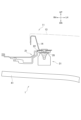
- FIG. 1 is a cross-sectional view of a roof structure of a vehicle according to an embodiment.
- FIG. 2 is a cross-sectional view of the roof structure of the vehicle according to the embodiment.
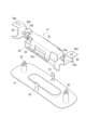
- FIG. 3A is a perspective view showing a structure of a bracket, a speaker, and a speaker grill in the roof structure of the vehicle according to the embodiment.
- FIG. 3B is a perspective view showing the structure of the bracket, the speaker, and the speaker grill in the vehicle roof structure according to the embodiment.
- FIG. 3C is a perspective view showing the structure of the bracket, the speaker, and the speaker grill in the vehicle roof structure according to the embodiment.
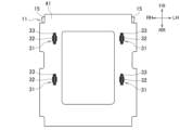
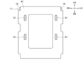
- FIG. 4A is a plan view seen from inside the vehicle compartment, showing a mounting process for the vehicle roof structure according to the embodiment.
- FIG. 4A is a plan view seen from inside the vehicle compartment, showing a mounting process for the vehicle roof structure according to the embodiment.
- FIG. 4B is a plan view seen from inside the vehicle compartment, showing the mounting process of the vehicle roof structure according to the embodiment.
- FIG. 4C is a plan view seen from inside the vehicle compartment, showing the mounting process of the vehicle roof structure according to the embodiment.
- FIG. 4D is a plan view seen from inside the vehicle compartment, showing the mounting process of the vehicle roof structure according to the embodiment.
- FIG. 5 is a cross-sectional view of a vehicle roof structure according to a modified example of the embodiment.
- the front of the vehicle is indicated as FR, the rear of the vehicle as RR, the right side of the vehicle as RH, the left side of the vehicle as LH, the top of the vehicle as UP, and the bottom of the vehicle as DN.
- the terms front, rear, right, left, top, and bottom refer to directions relative to the vehicle, unless otherwise specified.
- elements having the same functions are given the same reference numerals, and duplicate descriptions will be omitted.
- the roof structure of the vehicle according to this embodiment includes a roof panel 11 provided with a sunroof opening 12, a sunroof unit 21 attached to the sunroof opening 12, and a speaker unit 31.
- the speaker units 31 are installed on the left and right of the front and center of the roof panel 11.
- the structure of the speaker unit 31 provided on the front left side of the roof panel 11 and its surroundings will be described as an example.
- the structures of the other speaker units 31 and their surroundings are similar, so description thereof will be omitted. Note that the installation positions and number of the speaker units 31 are not limited to those described above.
- the roof panel 11 is a member that constitutes the upper part of the vehicle body, and is made of, for example, steel plate, aluminum plate, carbon material, etc.
- Figure 4A illustrates an example of the configuration of the roof panel 11 from the front to the center of the vehicle.
- the roof panel 11 may have a sunroof opening 12, a panel main body 13, roof reinforcements 14, roof side rails 15, 15, connection parts 16, 16, and a roof cross member 17. Note that the configuration of the roof panel 11 from the center to the rear of the vehicle is not illustrated.
- the panel body 13 is a plate that constitutes the roof panel 11.
- the sunroof opening 12 is a rectangular opening formed in the center of the panel body 13 in the vehicle width direction, from the front to the center.
- the roof reinforcement 14 is a member that reinforces the panel body 13.
- the roof reinforcement 14 has a rectangular frame shape that fits around the periphery of the sunroof opening 12.
- the roof reinforcement 14 is disposed on the passenger compartment inside side of the panel body 13 and is fixed to the panel body 13 (see Figure 4A).
- the roof side rails 15, 15 are structural members extending in the vehicle front-rear direction and are provided at both ends of the panel main body 13 (see FIG. 4A).
- the connection parts 16, 16 are members that connect the roof reinforcement 14 and the roof side rails 15, 15.
- the connection parts 16, 16 are provided between the roof reinforcement 14 and the roof side rails 15, 15 in a portion of the panel main body 13 from the center toward the front.
- the roof reinforcement 14 is supported by the roof side rails 15, 15 via the connection parts 16, 16.
- the roof cross member 17 is a structural member extending in the vehicle width direction and is provided at the center of the panel main body 13 (see FIG. 4A).
- the end of the roof reinforcement 14 near the center of the panel main body 13 is supported by the roof cross member 17.
- a sunroof unit 21 is attached to the sunroof opening 12 (see FIG. 4A).
- the sunroof unit 21 may include a frame portion 22 and a panel portion 23.
- the frame portion 22 has a rectangular frame shape formed along the periphery of the sunroof opening 12.
- the frame portion 22 is disposed below the roof panel 11, on the passenger compartment inside of the roof reinforcement 14, and is fixed to the roof reinforcement 14 (see FIG. 4A). That is, the sunroof unit 21 is supported by the roof panel 11 via the frame portion 22.
- the frame portion 22 has high rigidity to ensure the rigidity of the entire sunroof unit 21.
- the frame portion 22 is made of, for example, a steel plate, an aluminum plate, a carbon material, or the like.
- the panel portion 23 is fitted into the sunroof opening 12.
- the panel portion 23 may include a mechanism for sliding forward, backward, left, right, etc.
- the roof reinforcement 14, roof side rails 15, 15, connection parts 16, 16, roof cross member 17, and frame part 22 may have a closed cross-sectional shape or a hat-shaped cross-sectional shape in order to withstand the load of an impact or collision.
- the speaker unit 31 is fixed to the frame portion 22.
- the speaker unit 31 has a speaker 32 and a bracket 33.
- the bracket 33 is an attachment member for fixing the speaker 32 to the frame portion 22.
- the bracket 33 engages and holds the speaker 32.
- the bracket 33 may be fastened together to the frame portion 22 and the roof reinforcement 14.
- the bracket 33 may be fastened together at a plurality of fixing points 35.
- the bracket 33 has legs 36 and bracket attachment holes 36a provided at the bent tips of the legs 36.
- the direction connecting the bracket attachment holes 36a of the legs 36 is approximately the same as the fore-aft direction of the vehicle.
- the bracket 33 is fixed to the frame portion 22 and the roof reinforcement 14 with bolts and nuts, but the fixing method is not limited to this and it may be fixed with rivets or the like.
- the bracket 33 is made of metal, but is not limited to this and known materials such as resin (including fiber-reinforced resin) can be used.
- the headlining 41 is located inside the vehicle compartment relative to the roof panel 11 and the sunroof unit 21, and forms the ceiling of the vehicle compartment 1.
- the headlining 41 has holes 42 through which the speakers 32 are inserted and housed on the outside of the vehicle compartment.
- a harness connected to the port 34 of the speaker 32 is routed on the headlining 41.
- the speaker grill 51 is disposed inside the vehicle cabin from the speaker 32 and is engaged with the bracket 33 (see FIG. 3A). That is, the speaker 32 is housed between the bracket 33 and the speaker grill 51.
- the speaker grill 51 has locking clips 52, 52 provided at the front and rear, and locking pieces 53, 53 provided on the left and right.
- the speaker grill 51 is locked by inserting the locking clips 52, 52 and the locking pieces 53, 53 into the locking holes 33b, 33b and 33c, 33c provided in the bracket 33, respectively.
- the speaker grill 51 has a shape larger than the hole 42 in the headlining 41 so that no gap is generated between the speaker grill 51 and the hole 42 in the headlining 41 after the locking.
- the shape of the speaker grill 51 and the method of fixing it to the bracket 33 are not limited to the above.
- the speaker grill 51 is made of resin, but is not limited to this.
- the bracket attachment holes 36a, 36a of the legs 36, 36 of the bracket 33 are fastened together to the roof reinforcement 14 and the frame portion 22.
- the fastening together is performed at the fixing points 35, 35 (see Figures 2 and 4B).
- the headlining 41 is assembled to the roof panel 11 with the hole position of the headlining 41 aligned with the bracket 33 (see Figure 4C).
- the hole 42 of the headlining 41 is arranged at a position where the speaker 32 engaged and held by the bracket 33 can be inserted.
- a harness with a base end fixed thereto is arranged on the headlining 41.
- the headlining 41 is assembled to the roof panel 11 by, for example, placing an adhesive surface on the headlining 41 and attaching it to the surface of the roof panel 11.
- the speaker grill 51 is attached to the bracket 33 (see Figures 3C and 4D).
- the locking clips 52, 52 of the speaker grill 51 are inserted into the locking holes 33b, 33b of the bracket 33, and the locking pieces 53, 53 are inserted into the locking holes 33c, 33c to lock them in place.
- the hole 42 in the headlining 41 is blocked by the speaker grill 51, and the speaker unit 31 is installed in the roof structure of the vehicle according to the embodiment.
- the headlining 41 may be inclined toward the vehicle interior with respect to the frame part 22.
- the headlining 41 is inclined with respect to the interior side of the speaker unit 31. Therefore, when the speaker grill 51 is attached in this state, a gap may be generated between the speaker grill 51 and the headlining 41.
- the gap is not preferable from the viewpoints of the functionality of the speaker 32, the intrusion of dust, appearance, and the like.
- the speaker unit 31 is inclined with respect to the frame part 22, so that the fixing to the frame part 22 may be insufficient or difficult.
- the speaker unit 31 since the speaker unit 31 is disposed at an angle with respect to the seated occupant, the sound pressure may be reduced due to the reduction in sound energy delivered from the speaker 32 to the seated occupant. In addition, the sound quality may be reduced due to the deterioration of the audibility of the sound from the speaker 32.
- the legs 36, 36 of the bracket 33 have different lengths and are fixed at a plurality of fixing points 35, 35.
- the interior side surface of the speaker unit 31 is disposed at an incline with respect to the frame portion 22. There is no gap between the speaker grill 51 and the headlining 41.
- the length of the legs 36, 36 can be determined in consideration of the incline of the headlining 41 with respect to the frame portion 22, the gap between the speaker grill 51 and the headlining 41, and disposing the speaker 32 within a predetermined angle with respect to the seated occupant.
- the angle of the bent portion provided on the legs 36, 36 may be changed.
- the angle formed by a line connecting the center of the interior side surface of the speaker unit 31 to the head of the seated occupant and a perpendicular line to the interior side surface of the speaker unit 31 may be 0° or more and 30° or less.
- the roof structure of the vehicle according to the embodiment includes a roof panel 11 provided with a sunroof opening 12, a sunroof unit 21 attached to the sunroof opening 12, and a speaker unit 31.
- the sunroof unit 21 includes a frame portion 22 disposed on the lower side of the roof panel 11, and is supported by the roof panel 11 via the frame portion 22.
- the speaker unit 31 is fixed to the frame portion 22.
- the frame portion 22 to which the speaker unit 31 is fixed has high rigidity in order to ensure the rigidity of the entire sunroof unit 21. Therefore, the mounting rigidity of the speaker unit 31 is ensured.
- the driving force of the electromagnetic coil is transmitted to the diaphragm of the speaker 32 without loss during playback of the speaker 32, and deterioration of the sound pressure and sound quality of the speaker 32 is suppressed.
- the roof panel 11 is provided with a roof reinforcement 14 that reinforces the roof panel 11.
- the speaker unit 31 is fastened to the frame portion 22 of the sunroof unit 21 and the roof reinforcement 14 together.
- the roof reinforcement 14 to which the speaker unit 31 is fixed is a member that reinforces the roof panel 11.
- the frame portion 22 to which the speaker unit 31 is fixed has high rigidity in order to ensure the rigidity of the entire sunroof unit 21. Therefore, by fastening the speaker unit 31 to the frame portion 22 and the roof reinforcement 14 together, the mounting rigidity of the speaker unit 31 is further ensured. Therefore, the driving force of the electromagnetic coil is transmitted to the diaphragm of the speaker 32 without loss during playback of the speaker 32, and deterioration in sound pressure and sound quality of the speaker 32 is further suppressed.
- the speaker unit 31 has a bracket 33.
- the bracket 33 is fastened together with the frame portion 22 of the sunroof unit 21 and the roof reinforcement 14 at a plurality of fastening points 35, 35. Since the bracket 33 of the speaker unit 31 is fastened together with the roof reinforcement 14 and the frame portion 22 at a plurality of fastening points 35, 35, the mounting rigidity of the speaker unit 31 is further ensured.
- the bracket 33 has legs 36, 36 that are fixed to the multiple fixing points 35, 35, respectively.
- the legs 36, 36 each have a different length. This allows the speaker unit 31 to be positioned at a predetermined angle with respect to the seated occupant, thereby suppressing deterioration in sound quality of the speaker 32.
- the vehicle roof structure to which the speaker unit 31 is attached is provided on the left and right sides of the front and center of the roof panel 11, but this is not limited, and the speaker unit 31 may be provided at any position around the sunroof opening 12 provided in the roof panel 11. Furthermore, there is no particular limit to the positions and number of the vehicle roof structures according to the modified examples of the above embodiment.
Landscapes
- Engineering & Computer Science (AREA)
- Mechanical Engineering (AREA)
- Fittings On The Vehicle Exterior For Carrying Loads, And Devices For Holding Or Mounting Articles (AREA)
- Body Structure For Vehicles (AREA)
Abstract
車両のルーフ構造は、サンルーフ開口(12)が設けられたルーフパネル(11)と、サンルーフ開口(12)に装着されたサンルーフユニット(21)と、スピーカーユニット(31)と、を備えている。サンルーフユニット(21)は、ルーフパネル(11)の下側に配置されたフレーム部(22)を含むとともに、該フレーム部(22)を介してルーフパネル(11)に支持されている。スピーカーユニット(31)は、フレーム部(22)に固定されている。
Description
本発明は、車両のルーフ構造に関するものである。
特許文献1は、車両用スピーカーをルーフライニングに取り付ける構造を開示している。
ところで、スピーカーを車両のルーフ構造に取り付ける場合、取付位置によっては、剛性が不足していることにより、スピーカーの音質に問題が生じることが有った。
本発明の目的は、スピーカーの取付剛性を向上させることができる車両のルーフ構造を提供することである。
本発明の一態様に係る車両のルーフ構造は、サンルーフ開口が設けられたルーフパネルと、サンルーフ開口に装着されたサンルーフユニットと、スピーカーユニットと、を備えている。サンルーフユニットは、ルーフパネルの下側に配置されたフレーム部を含むとともに、該フレーム部を介してルーフパネルに支持されている。スピーカーユニットは、フレーム部に固定されている。
本発明によれば、スピーカーの取付剛性を向上させることができる車両のルーフ構造を提供することができる。
以下、図面を参照しながら、実施形態に係る車両用テーブルについて説明する。図面において、車両前方をFR、車両後方をRR、車両右方をRH、車両左方をLH、車両上方をUP、車両下方をDNで示す。以下の説明における、前方、後方、右方、左方、上方、下方という用語は、特に断わりのない限り、上記の車両を基準とした方向を意味する。なお、以下の説明では同一の機能を有する要素については同一の符号を付し、重複する説明を省略する。
(実施形態)
(車両のルーフ構造の構成例)
図1に例示したように、本実施形態に係る車両のルーフ構造は、サンルーフ開口12が設けられたルーフパネル11と、サンルーフ開口12に装着されたサンルーフユニット21と、スピーカーユニット31と、を備えている。実施形態に係る車両において、スピーカーユニット31は、ルーフパネル11の前部及び中央部の左右に、それぞれ設置されている。以下、ルーフパネル11の前部左側に設けられたスピーカーユニット31及びその周辺部の構造を例として説明する。他のスピーカーユニット31及びその周辺部の構造は、同様であるため、説明を省略する。なお、スピーカーユニット31の設置位置及び個数は、上記に限定されない。
(車両のルーフ構造の構成例)
図1に例示したように、本実施形態に係る車両のルーフ構造は、サンルーフ開口12が設けられたルーフパネル11と、サンルーフ開口12に装着されたサンルーフユニット21と、スピーカーユニット31と、を備えている。実施形態に係る車両において、スピーカーユニット31は、ルーフパネル11の前部及び中央部の左右に、それぞれ設置されている。以下、ルーフパネル11の前部左側に設けられたスピーカーユニット31及びその周辺部の構造を例として説明する。他のスピーカーユニット31及びその周辺部の構造は、同様であるため、説明を省略する。なお、スピーカーユニット31の設置位置及び個数は、上記に限定されない。
ルーフパネル11は、車体上部を構成する部材であり、例えば、鋼板、アルミ板、カーボン素材等で構成される。図4Aは、車両の前部から中央部におけるルーフパネル11の構成を例示している。図に例示するように、ルーフパネル11は、サンルーフ開口12と、パネル本体部13と、ルーフレインフォース14と、ルーフサイドレール15,15と、接続部16,16と、ルーフクロスメンバ17と、を有していてもよい。なお、車両の中央部から後部におけるルーフパネル11の構成は、図示を省略する。
パネル本体部13は、ルーフパネル11を構成する板体である。サンルーフ開口12は、パネル本体部13の前部から中央部にかけて、車幅方向における中央部分に形成された矩形状の開口である。
ルーフレインフォース14は、パネル本体部13を補強する部材である。ルーフレインフォース14は、サンルーフ開口12の周囲に沿って、矩形枠状の形状を有している。ルーフレインフォース14は、パネル本体部13の車室内側に配置され、パネル本体部13に固定されている(図4A参照)。
ルーフサイドレール15,15は、車両前後方向に延びる骨格構造部材であり、パネル本体部13の両端に設けられている(図4A参照)。接続部16,16は、ルーフレインフォース14とルーフサイドレール15,15とを接続する部材である。接続部16,16は、パネル本体部13の中央部から前部寄りの部分において、ルーフレインフォース14とルーフサイドレール15,15との間に設けられている。ルーフレインフォース14は、接続部16,16を介して、ルーフサイドレール15,15に支持されている。ルーフクロスメンバ17は、車幅方向に延びる骨格構造部材であり、パネル本体部13の中央部に設けられている(図4A参照)。ルーフレインフォース14のパネル本体部13の中央部寄りの端部は、ルーフクロスメンバ17に支持されている。
サンルーフ開口12には、サンルーフユニット21が装着されている(図4A参照)。サンルーフユニット21は、フレーム部22と、パネル部23と、を備えていてもよい。フレーム部22は、サンルーフ開口12の周囲に沿って、矩形に形成された枠状形状を有している。フレーム部22は、ルーフパネル11の下側であって、ルーフレインフォース14の車室内側に配置され、ルーフレインフォース14に固定されている(図4A参照)。即ち、サンルーフユニット21は、フレーム部22を介してルーフパネル11に支持されている。フレーム部22は、サンルーフユニット21全体の剛性を確保するために、高い剛性を有している。フレーム部22は、例えば、鋼板、アルミ板、カーボン素材等で構成される。パネル部23は、サンルーフ開口12に嵌め込まれている。パネル部23は、前後左右等にスライドする機構を備えていてもよい。なお、ルーフレインフォース14、ルーフサイドレール15,15、接続部16,16、ルーフクロスメンバ17、フレーム部22は、衝撃や衝突の荷重を受け止めるため、閉断面形状やハット形断面形状を有してもよい。
スピーカーユニット31は、フレーム部22に固定されている。スピーカーユニット31は、スピーカー32と、ブラケット33と、を有している。
スピーカー32は、後述するヘッドライニング41に開口する孔42に挿通され、ブラケット33に係合保持されている(図1参照)。ヘッドライニング41は、車室1の天井を構成している。従って、車室内側から見た場合、スピーカー32は、孔42を介して車室内側へ露出する位置に配置されている。ハーネス(不図示)が接続されるポート34は、スピーカー32の側面において、ヘッドライニング41より車室外側の位置に設けられている(図1参照)。ポート34は、スピーカー32を駆動するアンプに接続されている。スピーカー32は、取付孔32c,32cを介して、ボルトとナットとによりブラケット固定点33a,33aに固定されてもよい。なお、スピーカー32の形状は上記に限定されず、ブラケット33に係合保持される形状から、任意に選択することができる。
ブラケット33は、フレーム部22にスピーカー32を固定するための取付部材である。ブラケット33は、スピーカー32を係合保持している。図2に例示したように、ブラケット33は、フレーム部22と、ルーフレインフォース14とに、共締め固定されていてもよい。ブラケット33は、複数の固定点35,35において共締め固定されていてもよい。図3Aに例示したように、ブラケット33は、脚部36,36と、脚部36,36の屈曲した先端部に設けられたブラケット取付孔36a,36aと、を有している。図1に例示したように、脚部36,36のブラケット取付孔36a,36aを結ぶ方向は、車両前後方向に略一致している。以下、ブラケット取付孔36a,36aを結ぶ方向を前後方向とし、前後方向及び車室内側方向と直交する方向を、幅方向とする。なお、ブラケット33は、ボルトとナットとによりフレーム部22とルーフレインフォース14へ固定されているが、固定方法はこれに限定されず、リベット等で固定してもよい。ブラケット33は金属製であるが、これに限定されず、樹脂(繊維強化樹脂を含む)等の公知の材料を用いることができる。
図1に例示したように、ヘッドライニング41は、ルーフパネル11及びサンルーフユニット21より車室内側に位置し、車室1の天井を構成している。ヘッドライニング41は、スピーカー32を挿通して車室外側へ収容する孔42を有している。ヘッドライニング41上には、スピーカー32のポート34と接続されているハーネスが配索されている。
スピーカーグリル51は、スピーカー32より車室内側に配置され、ブラケット33に係止されている(図3A参照)。即ち、ブラケット33とスピーカーグリル51との間に、スピーカー32が収容されている。スピーカーグリル51は、前部及び後部に設けられた係止クリップ52,52と、左右に設けられた係止片53,53と、を有している。係止クリップ52,52、係止片53,53を、それぞれブラケット33に設けられた係止口33b,33b及び33c,33cに挿入することにより、スピーカーグリル51が係止される。スピーカーグリル51は、係止後の状態においてスピーカーグリル51とヘッドライニング41の孔42との間に隙間が生じないように、孔42よりも大きい形状を有している。なお、スピーカーグリル51の形状、ブラケット33への固定方法は、上記に限定されない。スピーカーグリル51は樹脂製であるが、これに限定されない。
(スピーカーユニットの取付工程)
次に、図4A~4Dを参照して、実施形態に係る車両のルーフ構造におけるスピーカーユニット31の取付工程について説明する。まず、ブラケット33の脚部36,36のブラケット取付孔36a,36aを、ルーフレインフォース14及びフレーム部22に共締め固定する。当該共締め固定は、固定点35,35においてなされる(図2、4B参照)。次に、ブラケット33にヘッドライニング41の孔の位置を合わせた状態で、ヘッドライニング41をルーフパネル11に組み付ける(図4C参照)。ヘッドライニング41の孔42は、ブラケット33に係合保持されるスピーカー32を挿通可能な位置に配置されている。ヘッドライニング41上には、基端を固定されたハーネスが配置されている。なお、ルーフパネル11へのヘッドライニング41の組み付けは、例えばヘッドライニング41上に粘着面を配置し、ルーフパネル11表面に貼り合わせることにより行う。
次に、図4A~4Dを参照して、実施形態に係る車両のルーフ構造におけるスピーカーユニット31の取付工程について説明する。まず、ブラケット33の脚部36,36のブラケット取付孔36a,36aを、ルーフレインフォース14及びフレーム部22に共締め固定する。当該共締め固定は、固定点35,35においてなされる(図2、4B参照)。次に、ブラケット33にヘッドライニング41の孔の位置を合わせた状態で、ヘッドライニング41をルーフパネル11に組み付ける(図4C参照)。ヘッドライニング41の孔42は、ブラケット33に係合保持されるスピーカー32を挿通可能な位置に配置されている。ヘッドライニング41上には、基端を固定されたハーネスが配置されている。なお、ルーフパネル11へのヘッドライニング41の組み付けは、例えばヘッドライニング41上に粘着面を配置し、ルーフパネル11表面に貼り合わせることにより行う。
次に、ハーネスをスピーカー32の側面のポート34に接続する。そして、スピーカー32をブラケット33に取り付ける(図3B、4C参照)。
次に、スピーカーグリル51をブラケット33へ係止する(図3C、4D参照)。スピーカーグリル51の係止クリップ52,52をブラケット33の係止口33b,33bに挿入し、係止片53,53を係止口33c,33cに挿入して係止する。これにより、ヘッドライニング41の孔42は、スピーカーグリル51により塞がれ、実施形態に係る車両のルーフ構造におけるスピーカーユニット31が設置される。
(変形例)
図5に例示したように、スピーカーユニット31の設置場所によっては、フレーム部22に対してヘッドライニング41が車室内側に傾斜していることが有る。その場合、スピーカーユニット31をフレーム部22に固定すると、スピーカーユニット31の車室内側面に対して、ヘッドライニング41が傾斜している。従って、この状態でスピーカーグリル51を装着すると、スピーカーグリル51とヘッドライニング41との間に隙間が生じうる。当該隙間は、スピーカー32の機能面、塵の侵入、見栄え等の観点から好ましくない。これに対し、スピーカーユニット31の車室内側面をヘッドライニング41の車室内側面に合わせる場合は、フレーム部22に対しスピーカーユニット31が傾斜しているため、フレーム部22への固定が不十分、あるいは困難であることが有る。また、スピーカーユニット31が着座している乗員に対して傾斜して配置されるため、着座している乗員にとって、スピーカー32から届く音エネルギーの低下により音圧が低下して聴こえることが有る。また、スピーカー32からの音の聴こえ方の劣化等により、音質が低下して聴こえることが有る。図5に例示した変形例では、ブラケット33の脚部36,36は、それぞれ異なる長さを有し、複数の固定点35,35において固定されている。スピーカーユニット31の車室内側面は、フレーム部22に対して傾斜して配置されている。スピーカーグリル51とヘッドライニング41との間に、隙間は生じていない。脚部36,36の長さは、フレーム部22に対するヘッドライニング41の傾斜、スピーカーグリル51とヘッドライニング41との間の隙間、着座している乗員に対し所定角度内にスピーカー32を配置すること等を考慮して、構成することができる。また、脚部36,36に設けられた屈曲部分の角度を変更してもよい。着座している乗員に対する適切な角度範囲の一例として、スピーカーユニット31の車室内側面中心と着座している乗員の頭部とを結ぶ線と、スピーカーユニット31の車室内側面の垂直線とがなす角度は、0°以上30°以下としてもよい。
図5に例示したように、スピーカーユニット31の設置場所によっては、フレーム部22に対してヘッドライニング41が車室内側に傾斜していることが有る。その場合、スピーカーユニット31をフレーム部22に固定すると、スピーカーユニット31の車室内側面に対して、ヘッドライニング41が傾斜している。従って、この状態でスピーカーグリル51を装着すると、スピーカーグリル51とヘッドライニング41との間に隙間が生じうる。当該隙間は、スピーカー32の機能面、塵の侵入、見栄え等の観点から好ましくない。これに対し、スピーカーユニット31の車室内側面をヘッドライニング41の車室内側面に合わせる場合は、フレーム部22に対しスピーカーユニット31が傾斜しているため、フレーム部22への固定が不十分、あるいは困難であることが有る。また、スピーカーユニット31が着座している乗員に対して傾斜して配置されるため、着座している乗員にとって、スピーカー32から届く音エネルギーの低下により音圧が低下して聴こえることが有る。また、スピーカー32からの音の聴こえ方の劣化等により、音質が低下して聴こえることが有る。図5に例示した変形例では、ブラケット33の脚部36,36は、それぞれ異なる長さを有し、複数の固定点35,35において固定されている。スピーカーユニット31の車室内側面は、フレーム部22に対して傾斜して配置されている。スピーカーグリル51とヘッドライニング41との間に、隙間は生じていない。脚部36,36の長さは、フレーム部22に対するヘッドライニング41の傾斜、スピーカーグリル51とヘッドライニング41との間の隙間、着座している乗員に対し所定角度内にスピーカー32を配置すること等を考慮して、構成することができる。また、脚部36,36に設けられた屈曲部分の角度を変更してもよい。着座している乗員に対する適切な角度範囲の一例として、スピーカーユニット31の車室内側面中心と着座している乗員の頭部とを結ぶ線と、スピーカーユニット31の車室内側面の垂直線とがなす角度は、0°以上30°以下としてもよい。
(作用効果)
(1)実施形態に係る車両のルーフ構造は、サンルーフ開口12が設けられたルーフパネル11と、サンルーフ開口12に装着されたサンルーフユニット21と、スピーカーユニット31と、を備えている。サンルーフユニット21は、ルーフパネル11の下側に配置されたフレーム部22を含むとともに、該フレーム部22を介してルーフパネル11に支持されている。スピーカーユニット31は、フレーム部22に固定されている。上記構成によれば、スピーカーユニット31が固定されているフレーム部22は、サンルーフユニット21全体の剛性を確保するため、高い剛性を有している。そのため、スピーカーユニット31の取付剛性が確保される。これにより、スピーカー32再生時に電磁コイルの駆動力がスピーカー32の振動板にロスなく伝わるようになり、スピーカー32の音圧低下や音質低下等が抑制される。
(1)実施形態に係る車両のルーフ構造は、サンルーフ開口12が設けられたルーフパネル11と、サンルーフ開口12に装着されたサンルーフユニット21と、スピーカーユニット31と、を備えている。サンルーフユニット21は、ルーフパネル11の下側に配置されたフレーム部22を含むとともに、該フレーム部22を介してルーフパネル11に支持されている。スピーカーユニット31は、フレーム部22に固定されている。上記構成によれば、スピーカーユニット31が固定されているフレーム部22は、サンルーフユニット21全体の剛性を確保するため、高い剛性を有している。そのため、スピーカーユニット31の取付剛性が確保される。これにより、スピーカー32再生時に電磁コイルの駆動力がスピーカー32の振動板にロスなく伝わるようになり、スピーカー32の音圧低下や音質低下等が抑制される。
(2)また、実施形態によれば、ルーフパネル11には、該ルーフパネル11を補強するルーフレインフォース14が設けられている。スピーカーユニット31は、サンルーフユニット21のフレーム部22とルーフレインフォース14とに共締め固定されている。上記構成によれば、スピーカーユニット31が固定されているルーフレインフォース14は、ルーフパネル11を補強する部材である。スピーカーユニット31が固定されているフレーム部22は、サンルーフユニット21全体の剛性を確保するため、高い剛性を有している。そのため、スピーカーユニット31がフレーム部22とルーフレインフォース14とに共締め固定されていることにより、スピーカーユニット31の取付剛性がより確保される。従って、スピーカー32再生時に電磁コイルの駆動力がスピーカー32の振動板にロスなく伝わるようになり、スピーカー32の音圧低下や音質低下等がより抑制される。
(3)さらに、実施形態によれば、スピーカーユニット31は、ブラケット33を有している。ブラケット33は、サンルーフユニット21のフレーム部22とルーフレインフォース14とに複数の固定点35,35において共締め固定されている。スピーカーユニット31の有するブラケット33が、ルーフレインフォース14及びフレーム部22とに複数の固定点35,35で共締め固定されているため、スピーカーユニット31の取り付け剛性がさらに確保される。
(4)また、実施形態の変形例に係る車両のルーフ構造によれば、ブラケット33は、複数の固定点35,35にそれぞれ固定される脚部36,36を有している。脚部36,36は、それぞれ異なる長さを有している。これにより、スピーカーユニット31を着座している乗員に対して所定角度で配置することができ、スピーカー32の音質低下を抑制する。
上記実施形態では、スピーカーユニット31を取り付ける車両のルーフ構造は、ルーフパネル11の前部及び中央部の左右に設けられているが、これに限らず、ルーフパネル11に設けられたサンルーフ開口12の周辺部において、任意の位置に設けられてもよい。また、上記実施形態の変形例に係る車両のルーフ構造が設置される位置及び個数は特に限定されない。
上記のように、本発明の実施形態を記載したが、この開示の一部をなす論述及び図面はこの発明を限定するものであると理解すべきではない。この開示から当業者には様々な代替実施の形態、実施例及び運用技術が明らかとなろう。
1 車室
11 ルーフパネル
12 サンルーフ開口
14 ルーフレインフォース
21 サンルーフユニット
22 フレーム部
31 スピーカーユニット
33 ブラケット
35 固定点
36 脚部
11 ルーフパネル
12 サンルーフ開口
14 ルーフレインフォース
21 サンルーフユニット
22 フレーム部
31 スピーカーユニット
33 ブラケット
35 固定点
36 脚部
Claims (4)
- サンルーフ開口が設けられたルーフパネルと、
前記サンルーフ開口に装着されたサンルーフユニットと、
スピーカーユニットと、
を備え、
前記サンルーフユニットは、前記ルーフパネルの下側に配置されたフレーム部を含むとともに、該フレーム部を介して前記ルーフパネルに支持されており、
前記スピーカーユニットは、前記フレーム部に固定されている、車両のルーフ構造。 - 前記ルーフパネルには、該ルーフパネルを補強するルーフレインフォースが設けられており、
前記スピーカーユニットは、前記サンルーフユニットの前記フレーム部と前記ルーフレインフォースとに共締め固定されている、請求項1に記載のルーフ構造。 - 前記スピーカーユニットは、ブラケットを有し、
前記ブラケットは、前記サンルーフユニットの前記フレーム部と前記ルーフレインフォースとに複数の固定点で共締め固定されている、請求項2に記載のルーフ構造。 - 前記ブラケットは、前記複数の固定点にそれぞれ固定される脚部を有し、
前記脚部は、それぞれ異なる長さを有している、請求項3に記載のルーフ構造。
Priority Applications (2)
| Application Number | Priority Date | Filing Date | Title |
|---|---|---|---|
| PCT/JP2023/022289 WO2024257311A1 (ja) | 2023-06-15 | 2023-06-15 | 車両のルーフ構造 |
| CN202380099370.2A CN121311387A (zh) | 2023-06-15 | 2023-06-15 | 车辆的车顶构造 |
Applications Claiming Priority (1)
| Application Number | Priority Date | Filing Date | Title |
|---|---|---|---|
| PCT/JP2023/022289 WO2024257311A1 (ja) | 2023-06-15 | 2023-06-15 | 車両のルーフ構造 |
Publications (1)
| Publication Number | Publication Date |
|---|---|
| WO2024257311A1 true WO2024257311A1 (ja) | 2024-12-19 |
Family
ID=93851688
Family Applications (1)
| Application Number | Title | Priority Date | Filing Date |
|---|---|---|---|
| PCT/JP2023/022289 Ceased WO2024257311A1 (ja) | 2023-06-15 | 2023-06-15 | 車両のルーフ構造 |
Country Status (2)
| Country | Link |
|---|---|
| CN (1) | CN121311387A (ja) |
| WO (1) | WO2024257311A1 (ja) |
Citations (4)
| Publication number | Priority date | Publication date | Assignee | Title |
|---|---|---|---|---|
| JPS6239319A (ja) * | 1985-08-16 | 1987-02-20 | Nissan Motor Co Ltd | サンル−フフレ−ムの取付構造 |
| JP2001130349A (ja) * | 1999-11-09 | 2001-05-15 | Auto Network Gijutsu Kenkyusho:Kk | 自動車天井の組付構造、同組付構造に用いるユニット部材、同組付構造に用いるフレーム部材および同組付方法 |
| CN208530246U (zh) * | 2017-06-27 | 2019-02-22 | 福特全球技术公司 | 用于车辆天窗开口的装饰部件和车顶 |
| CN215590463U (zh) * | 2021-10-08 | 2022-01-21 | 江苏铁锚玻璃股份有限公司 | 超高可靠性面发声透明天窗音响 |
-
2023
- 2023-06-15 CN CN202380099370.2A patent/CN121311387A/zh active Pending
- 2023-06-15 WO PCT/JP2023/022289 patent/WO2024257311A1/ja not_active Ceased
Patent Citations (4)
| Publication number | Priority date | Publication date | Assignee | Title |
|---|---|---|---|---|
| JPS6239319A (ja) * | 1985-08-16 | 1987-02-20 | Nissan Motor Co Ltd | サンル−フフレ−ムの取付構造 |
| JP2001130349A (ja) * | 1999-11-09 | 2001-05-15 | Auto Network Gijutsu Kenkyusho:Kk | 自動車天井の組付構造、同組付構造に用いるユニット部材、同組付構造に用いるフレーム部材および同組付方法 |
| CN208530246U (zh) * | 2017-06-27 | 2019-02-22 | 福特全球技术公司 | 用于车辆天窗开口的装饰部件和车顶 |
| CN215590463U (zh) * | 2021-10-08 | 2022-01-21 | 江苏铁锚玻璃股份有限公司 | 超高可靠性面发声透明天窗音响 |
Also Published As
| Publication number | Publication date |
|---|---|
| CN121311387A (zh) | 2026-01-09 |
Similar Documents
| Publication | Publication Date | Title |
|---|---|---|
| US6634694B2 (en) | Vehicular footrest construction | |
| JP5879938B2 (ja) | 車両後部の側部パネルの補強構造 | |
| CN108100044B (zh) | 机动车混合式搁架组件 | |
| JPWO2011045982A1 (ja) | 車体後部構造 | |
| WO2008062763A1 (fr) | Structure de renfort de carrosserie de véhicule | |
| JP2019010924A (ja) | ピラー骨格構造及び車体モジュール構造 | |
| JP4092505B2 (ja) | コックピットモジュールの取付構造 | |
| US8371632B2 (en) | Mounting structure for a pillar garnish | |
| JP5495103B2 (ja) | 車両のコントローラ取付構造 | |
| JP4314991B2 (ja) | 車体後部構造 | |
| WO2024257311A1 (ja) | 車両のルーフ構造 | |
| KR102881861B1 (ko) | 차체 후방 연결 구조 | |
| JP2009119925A (ja) | 自動車用ガラスサンルーフの補強構造 | |
| JP3705063B2 (ja) | 車両用シートベルト | |
| JP2006282122A (ja) | 自動車用シートベルトのリトラクタ取付構造 | |
| JP4296823B2 (ja) | 車両天井構造 | |
| JP2005319941A (ja) | 車体構造 | |
| JP2021054156A (ja) | 車両のフロア構造 | |
| JP3376815B2 (ja) | 自動車のサイドパネル補強構造 | |
| JP2000095060A (ja) | 車両用シートベルトのアンカーブラケット取付け構造 | |
| JP2010247613A (ja) | シートベルトリトラクタ取付構造 | |
| JP3428223B2 (ja) | ダッシュサイドプレートの取付構造 | |
| JP2025036898A (ja) | インストルメントパネルの取付構造 | |
| JP2541768Y2 (ja) | 自動車の下部車体構造 | |
| JP2010215196A (ja) | 自動車の車体構造 |
Legal Events
| Date | Code | Title | Description |
|---|---|---|---|
| 121 | Ep: the epo has been informed by wipo that ep was designated in this application |
Ref document number: 23940940 Country of ref document: EP Kind code of ref document: A1 |
|
| ENP | Entry into the national phase |
Ref document number: 2025527163 Country of ref document: JP Kind code of ref document: A |
|
| WWE | Wipo information: entry into national phase |
Ref document number: 2025527163 Country of ref document: JP |
|
| NENP | Non-entry into the national phase |
Ref country code: DE |