WO2024257434A1 - Apparatus and method for producing synthetic fuel - Google Patents
Apparatus and method for producing synthetic fuel Download PDFInfo
- Publication number
- WO2024257434A1 WO2024257434A1 PCT/JP2024/012434 JP2024012434W WO2024257434A1 WO 2024257434 A1 WO2024257434 A1 WO 2024257434A1 JP 2024012434 W JP2024012434 W JP 2024012434W WO 2024257434 A1 WO2024257434 A1 WO 2024257434A1
- Authority
- WO
- WIPO (PCT)
- Prior art keywords
- reactor
- material gas
- synthetic fuel
- raw material
- fuel
- Prior art date
- Legal status (The legal status is an assumption and is not a legal conclusion. Google has not performed a legal analysis and makes no representation as to the accuracy of the status listed.)
- Ceased
Links
Images



Classifications
-
- C—CHEMISTRY; METALLURGY
- C10—PETROLEUM, GAS OR COKE INDUSTRIES; TECHNICAL GASES CONTAINING CARBON MONOXIDE; FUELS; LUBRICANTS; PEAT
- C10G—CRACKING HYDROCARBON OILS; PRODUCTION OF LIQUID HYDROCARBON MIXTURES, e.g. BY DESTRUCTIVE HYDROGENATION, OLIGOMERISATION, POLYMERISATION; RECOVERY OF HYDROCARBON OILS FROM OIL-SHALE, OIL-SAND, OR GASES; REFINING MIXTURES MAINLY CONSISTING OF HYDROCARBONS; REFORMING OF NAPHTHA; MINERAL WAXES
- C10G2/00—Production of liquid hydrocarbon mixtures of undefined composition from oxides of carbon
- C10G2/50—Production of liquid hydrocarbon mixtures of undefined composition from oxides of carbon from carbon dioxide with hydrogen
Definitions
- the present invention relates to a synthetic fuel manufacturing apparatus and method for producing a specific synthetic fuel, particularly jet fuel, by a direct FT synthesis reaction using a raw material gas containing hydrogen and carbon dioxide.
- a method for producing jet fuel using the Fischer-Tropsch (FT) synthesis reaction from synthesis gas containing hydrogen and carbon monoxide is known, for example as disclosed in Patent Document 1.
- FT Fischer-Tropsch
- a chemical reaction is used to synthesize alkanes from synthesis gas in a reactor filled with an FT catalyst for causing the FT synthesis reaction, and FT crude oil containing a variety of hydrocarbons is produced.
- FT crude oil containing a variety of hydrocarbons is produced.
- an FT catalyst is proposed for producing hydrocarbons with a carbon number of 5 or more at a high yield using a mixed gas of hydrogen and carbon dioxide as the raw material gas.
- This FT catalyst is composed of catalytic metals containing Fe (iron) and Zr (zirconium), Ga (gallium), and Na (sodium).
- the above-mentioned FT catalyst does not provide sufficient selectivity for synthetic fuel suitable for jet fuel, specifically synthetic fuel containing hydrocarbons with 8 to 16 carbon atoms, in the synthetic fuel produced.
- the inventors discovered that it is possible to increase the selectivity for hydrocarbons with a desired carbon number based on the relationship between the FT catalyst packed in the reactor and the flow rate and flow speed of the raw material gas supplied to the reactor, and thus completed the present invention.
- the present invention has been made to solve the above problems, and aims to provide a synthetic fuel production device and method that can obtain a specific synthetic fuel, particularly hydrocarbons with a high selectivity for jet fuel components, and produce jet fuel with a high yield.
- the invention of claim 1 is a synthetic fuel production device (synthetic fuel production device 1 in this embodiment (hereinafter the same in this section)) for producing a specified synthetic fuel by a direct FT synthesis reaction using a raw material gas containing hydrogen and carbon dioxide, and is equipped with a reactor 9 having a cylindrical reactor main body 9a and filled with a specified FT catalyst 20 for causing a direct FT synthesis reaction in the reactor main body, an adjustment unit (raw material gas flow rate adjustment unit 7 and/or composition adjustment units 5a, 5b) for adjusting the flow rate of the raw material gas supplied to the reactor, and a control means (control device 3) for controlling the linear velocity, which is the flow rate of the raw material gas per cross-sectional area of the reactor main body by controlling this adjustment unit, and the control means is characterized in that when the specified synthetic fuel is jet fuel, the linear velocity is controlled to 0.2 to 4.0 m/sec.
- the reactor has a cylindrical reactor body, and this reactor body is filled with a specified FT catalyst for causing a direct FT synthesis reaction.
- the control means controls an adjustment unit for adjusting the flow rate of the raw material gas supplied to the reactor.
- the linear velocity which is the flow rate of the raw material gas per cross-sectional area of the reactor body, is controlled to 0.2 to 4.0 m/sec.
- the invention according to claim 2 is the synthetic fuel production device according to claim 1, characterized in that the control means controls the linear velocity to 2.7 to 3.0 m/sec.
- the linear velocity can be controlled to 2.7 to 3.0 m/sec by the control means, making it possible to obtain jet fuel component hydrocarbons with a higher selectivity.
- the invention of claim 3 is a synthetic fuel manufacturing method for manufacturing a specified synthetic fuel by a direct FT synthesis reaction using a raw material gas containing hydrogen and carbon dioxide, and is characterized by comprising a reactor preparation process for preparing a reactor 9 in which a cylindrical reactor body 9a is filled with an FT catalyst for causing a direct FT synthesis reaction, and a raw material gas supply process for supplying the raw material gas to the reactor so that the linear velocity, which is the flow rate of the raw material gas per cross-sectional area of the reactor body, is 0.2 to 4.0 m/sec when the specified synthetic fuel is jet fuel.
- a reactor is prepared with a specified FT catalyst packed in the cylindrical reactor body (reactor preparation process).
- the feed gas is supplied to the reactor so that the linear velocity, which is the flow rate of the feed gas per cross-sectional area of the reactor body, is 0.2 to 4.0 m/sec (feed gas supply process).
- FIG. 1 is a diagram showing a schematic diagram of a synthetic fuel production apparatus to which a synthetic fuel production apparatus and production method according to an embodiment of the present invention are applied.
- FIG. 2A is a diagram showing a reactor packed with an FT catalyst
- FIG. 2B is a diagram for explaining the linear velocity of a raw material gas supplied to the reactor.
- 1 is a graph showing the distillation properties of synthetic fuels obtained when the feed gas is supplied to a reactor at a high linear velocity and a low linear velocity.
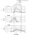
- 1 is a graph showing a hydrocarbon distribution indicating the relationship between the carbon number and weight of the hydrocarbons contained in a synthetic fuel, in which (a) shows the hydrocarbon distribution of a Jet-A1 standard jet fuel, (b) shows the hydrocarbon distribution of a synthetic fuel obtained at a low linear velocity, and (c) shows the hydrocarbon distribution of a synthetic fuel obtained at a high linear velocity.
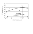
- 1 is a graph showing the relationship between the feed gas linear velocity and the jet fuel selectivity based on test results.
- 1 is a graph showing the pore distribution, which indicates the relationship between pore size and pore volume, for two types of FT catalysts.
- FIG. 1 shows a schematic diagram of a synthetic fuel production apparatus to which a synthetic fuel production apparatus and production method according to one embodiment of the present invention is applied.
- this synthetic fuel production apparatus 1 comprises a raw material gas supply section, a composition adjustment section, a compression section, a flow rate adjustment section, a preheating section, a catalytic reaction section, a cooling section, a gas-liquid separation section, and a collection section, which are connected via piping 2 and are controlled by a control device 3 (control means).
- the raw material gas supply unit has an H2 supply unit 4a and a CO2 supply unit 4b, which supply hydrogen and carbon dioxide, respectively.
- an H2 composition adjustment unit 5a and a CO2 composition adjustment unit 5b are provided downstream of the H2 supply unit 4a and the CO2 supply unit 4b, respectively.
- these H2 composition adjustment units 5a and CO2 composition adjustment units 5b are controlled by the control device 3, and can adjust the flow rate of the raw material gas alone or in cooperation with a raw material gas flow rate adjustment unit 7 described later.
- the compression section has a compressor 6, and is controlled by the control device 3 to pressurize the raw material gas to a predetermined pressure (e.g., 3 MPa).
- the flow rate adjustment section has a raw material gas flow rate adjustment section 7, and is controlled by the control device 3 to adjust the flow rate of the raw material gas compressed by the compressor 6.
- the preheating section has a preheating tube 8a and a preheater 8b, and the preheater 8b is controlled by the control device 3, so that the raw material gas passing through the preheating tube 8a connected to the piping 2 is heated to a predetermined temperature.
- the catalytic reaction section has a reactor 9 and a temperature adjustment section 10.
- the reactor 9 has a cylindrical reactor body 9a having a predetermined inner diameter, and the reactor body 9a is filled with the FT catalyst 20.
- the preparation of the reactor 9 by filling the reactor body 9a with the FT catalyst 20 corresponds to the reactor preparation step in the synthetic fuel production method of the present invention, and this reactor preparation step may include a step of heating the inside of the reactor 9 to a predetermined temperature (such as a reaction temperature) using an inert gas or the like.
- the FT catalyst 20 is for producing a plurality of types of hydrocarbons having different carbon numbers by causing a direct FT synthesis reaction in the raw material gas supplied to the reactor 9.
- the FT catalyst 20 is similar to the FT catalyst disclosed in Japanese Patent Application No. 2022-052774 already filed by the present applicant, and specifically, is configured to contain Fe, Zr, Ga, and Na as metal catalysts.
- the FT catalyst 20 is composed of a large number of pellets each having a predetermined size and shape, and each is configured to have a large number of pores. These pores have a specific surface area of about 30 m 2 /g and an average pore diameter of 10 to 100 nm.
- the temperature adjustment unit 10 in the catalytic reaction section is controlled by the control device 3, and the direct FT synthesis reaction occurring in the reactor 9 is adjusted to a predetermined temperature (e.g., 380°C).
- the raw material gas is kept at high pressure from the compression section to the catalytic reaction section described above, and as shown by the one-dot chain line in Figure 1, the raw material gas is heated from the preheating section to the catalytic reaction section.
- the cooling section has a cooler 11, and the product discharged from the reactor 9 is cooled by controlling the cooler 11 with the control device 3.
- the gas-liquid separation section has a gas-liquid separator 12, which separates the product that has been liquefied by cooling in the cooler 11 from the gaseous post-reaction gas that has not reacted or has not been liquefied.
- a gas-liquid separator 12 which separates the product that has been liquefied by cooling in the cooler 11 from the gaseous post-reaction gas that has not reacted or has not been liquefied.
- the collection section has a collection tank 13, which collects the liquid product separated by the gas-liquid separator 12.
- the synthetic fuel production device 1 configured as described above, as shown below, by causing a direct FT synthesis reaction while controlling the linear velocity of the raw material gas supplied to the reactor 9 within a predetermined range, it is possible to obtain synthetic fuel containing hydrocarbons with a high selectivity for jet fuel components, and to produce jet fuel with a high yield.
- Figure 3 shows the results of a distillation test of the synthetic fuel obtained by using the synthetic fuel production device 1 to supply raw material gas to the reactor 9 at a relatively low linear velocity (0.123 m/sec) and a relatively high linear velocity (2.88 m/sec) and causing a direct FT synthesis reaction under specified conditions (reactor temperature: 380°C, reactor pressure: 3 MPa), with the horizontal axis showing the distillate amount (wt%) and the vertical axis showing the distillate temperature (°C).
- the distillate temperatures TH and TL in the figure respectively indicate the upper and lower limit distillation temperatures suitable for jet fuel components, and specifically, for example, the upper limit distillation temperature TH is 232°C and the lower limit distillation temperature TL is 157°C.
- the selectivity of jet fuel was 20% in the synthetic fuel obtained by supplying the raw material gas to reactor 9 at a low linear velocity.
- Figure 4 also shows the hydrocarbon distribution, which indicates the relationship between the carbon number and weight of the hydrocarbons contained in the synthetic fuel obtained at the low and high linear velocities described above, with the solid line indicating straight-chain hydrocarbons and the dashed line indicating aromatic hydrocarbons.
- Figure 4(a) shows the hydrocarbon distribution of jet fuel of a specified standard (Jet-A1).
- Jet-A1 jet fuel includes hydrocarbons with carbon numbers between 7 and 20, and in particular, the majority of hydrocarbons have carbon numbers between 8 and 16, which is in the range suitable for jet fuel (hereinafter referred to as the "Jet range").
- the synthetic fuel obtained at low linear velocity contains hydrocarbons with carbon numbers between 3 and 13.
- the synthetic fuel obtained at low linear velocity contains few hydrocarbons in the Jet range, and therefore is insufficient as hydrocarbons with the carbon number required for jet fuel components.
- the synthetic fuel obtained at high linear velocity contains hydrocarbons with carbon numbers between 4 and 20, and in particular contains a large amount of hydrocarbons in the Jet range, which has carbon numbers between 8 and 16. This shows that the synthetic fuel obtained at high linear velocity contains a sufficient amount of hydrocarbons with the carbon numbers required for jet fuel components.
- Figure 5 shows the relationship between the feed gas linear velocity and the Jet fuel selectivity based on the test results described above.
- the maximum feed gas linear velocity in the test described above is 3.0
- the Jet fuel selectivity for feed gas linear velocities of 3.0 to 4.0 m/sec is shown by a two-dot chain imaginary line.
- the upper limit of the favorable linear velocity range in which the Jet fuel selectivity is 40% or more is set to 4.0 m/sec.
- the graph in Figure 5 shows that the feed gas linear velocity at which a jet fuel selectivity of 40% or more and a relatively good jet fuel selectivity can be obtained is 0.2 to 4.0 m/sec (good linear velocity range).
- the feed gas linear velocity at which a relatively high jet fuel selectivity of 50% or more can be obtained is 2.7 to 3.0 m/sec (best linear velocity range).
- Figure 6 shows the pore distributions, which indicate the relationship between pore size and pore volume, for two types of FT catalysts, C1 and C2, both of which have a large number of pores.
- the average pore size and median pore size of FT catalyst C1 are 31.5 and 38.6 nm, respectively
- the average pore size and median pore size of FT catalyst C2 are 25.5 and 20.7 nm, respectively.
- the pore distributions shown in Figure 6 were measured by a gas adsorption method using nitrogen.
- the average diameter of the pores is 10 to 100 nm, which can improve the yield of higher hydrocarbons with 8 or more carbon atoms required for jet fuel. This is believed to be due to the following reasons. That is, if the average pore diameter is less than 10 nm, the raw material gas will have difficulty reaching deep into the pores in the FT catalyst 20, and there is a risk that the direct FT synthesis reaction will not be sufficiently promoted.
- the average pore diameter of the FT catalyst 20 is 10 to 100 nm.
- a raw material gas containing hydrogen and carbon dioxide is supplied to the reactor 9 filled with the FT catalyst 20 at a linear velocity of 0.2 to 4.0 m/sec, which makes it possible to obtain hydrocarbons with a high selectivity for jet fuel components and produce jet fuel with a high yield.
- the linear velocity is set to 2.7 to 3.0 m/sec, it is possible to obtain hydrocarbons of jet fuel components with a higher selectivity.
- an FT catalyst 20 containing Fe, Zr, Ga, and Na is used to cause a direct FT synthesis reaction, but other catalysts can be used as long as they can cause a direct FT synthesis reaction in a raw material gas containing hydrogen and carbon dioxide.
- Synthetic fuel production device 2 Pipe 3 Control device (control means) 4a H2 supply unit 4b CO2 supply unit 5a H2 composition adjustment unit 5b CO2 composition adjustment unit 6 Compressor 7 Raw material gas flow rate adjustment unit (flow rate adjustment unit) 8a Preheating tube 8b Preheater 9 Reactor 9a Reactor main body 10 Temperature adjustment section 11 Cooler 12 Gas-liquid separator 13 Collection tank 20 FT catalyst
Landscapes
- Chemical & Material Sciences (AREA)
- Oil, Petroleum & Natural Gas (AREA)
- Engineering & Computer Science (AREA)
- Chemical Kinetics & Catalysis (AREA)
- General Chemical & Material Sciences (AREA)
- Organic Chemistry (AREA)
- Organic Low-Molecular-Weight Compounds And Preparation Thereof (AREA)
Abstract
Description
本発明は、水素と二酸化炭素を含む原料ガスを用い、ダイレクトFT合成反応によって所定の合成燃料、特にジェット燃料を製造するための合成燃料の製造装置及び製造方法に関する。 The present invention relates to a synthetic fuel manufacturing apparatus and method for producing a specific synthetic fuel, particularly jet fuel, by a direct FT synthesis reaction using a raw material gas containing hydrogen and carbon dioxide.
従来、水素と一酸化炭素を含む合成ガスから、FT(フィッシャー・トロプシュ:Fischer-Tropsch)合成反応を用いたジェット燃料の製造方法として、例えば特許文献1に開示されたものが知られている。このジェット燃料の製造方法では、FT合成反応を生じさせるためのFT触媒が充填された反応器内において、合成ガスからアルカンを合成する化学反応を利用して、多種の炭化水素を含むFT粗油を生成する。そして、このFT粗油に対し、複数の水素化処理、アルキル化処理及び芳香族化処理を組み合わせることによって、ジェット燃料に適した合成燃料の高収率化を図っている。
Conventionally, a method for producing jet fuel using the Fischer-Tropsch (FT) synthesis reaction from synthesis gas containing hydrogen and carbon monoxide is known, for example as disclosed in
また、近年、カーボンニュートラルの実現を目指して、合成ガスの一酸化炭素の代わりに二酸化炭素を用いてFT合成を行うダイレクトFT合成法の研究が行われている。本出願人がすでに出願した特願2022-052774号では、水素と二酸化炭素の混合ガスを原料ガスとして、炭素数が5以上の炭化水素を高収率で生成するためのFT触媒を提案している。このFT触媒は、触媒金属として、Fe(鉄)及びZr(ジルコニウム)を含み、またGa(ガリウム)を含んだり、さらにNa(ナトリウム)を含んだりすることによって構成されている。 In addition, in recent years, research has been conducted into a direct FT synthesis method in which FT synthesis is performed using carbon dioxide instead of carbon monoxide in synthetic gas, with the aim of achieving carbon neutrality. In Patent Application No. 2022-052774, already filed by the applicant, an FT catalyst is proposed for producing hydrocarbons with a carbon number of 5 or more at a high yield using a mixed gas of hydrogen and carbon dioxide as the raw material gas. This FT catalyst is composed of catalytic metals containing Fe (iron) and Zr (zirconium), Ga (gallium), and Na (sodium).
しかし、上記のFT触媒では、製造された合成燃料において、ジェット燃料に適した合成燃料、具体的には炭素数が8~16の炭化水素を含む合成燃料の選択率が不十分である。本発明者らは、鋭意研究を重ね、反応器に充填されるFT触媒と、反応器に供給される原料ガスの流量や流速との関係に基づき、所望の炭素数を有する炭化水素の選択率を高めることができることを見い出し、本発明を完成するに至った。 However, the above-mentioned FT catalyst does not provide sufficient selectivity for synthetic fuel suitable for jet fuel, specifically synthetic fuel containing hydrocarbons with 8 to 16 carbon atoms, in the synthetic fuel produced. After extensive research, the inventors discovered that it is possible to increase the selectivity for hydrocarbons with a desired carbon number based on the relationship between the FT catalyst packed in the reactor and the flow rate and flow speed of the raw material gas supplied to the reactor, and thus completed the present invention.
本発明は、以上のような課題を解決するためになされたものであり、所定の合成燃料、特にジェット燃料成分の選択率が高い炭化水素を得ることができ、高い収率でジェット燃料を製造することができる合成燃料の製造装置及び製造方法を提供することを目的とする。 The present invention has been made to solve the above problems, and aims to provide a synthetic fuel production device and method that can obtain a specific synthetic fuel, particularly hydrocarbons with a high selectivity for jet fuel components, and produce jet fuel with a high yield.
上記の目的を達成するために、請求項1に係る発明は、水素と二酸化炭素を含む原料ガスを用い、ダイレクトFT合成反応によって所定の合成燃料を製造するための合成燃料の製造装置(本実施形態における(以下、本項において同じ)合成燃料製造装置1)であって、筒状の反応器本体部9aを有し、反応器本体部にダイレクトFT合成反応を生じさせるための所定のFT触媒20が充填された反応器9と、反応器に供給される原料ガスの流量を調整するための調整部(原料ガス流量調整部7及び/又は組成調整部5a、5b、)と、この調整部を制御することにより、反応器本体部の横断面積当たりの原料ガスの流量である線速を制御する制御手段(制御装置3)と、を備え、制御手段は、所定の合成燃料がジェット燃料であるときに、線速を、0.2~4.0m/secに制御することを特徴とする。
In order to achieve the above object, the invention of
この構成によれば、反応器が筒状の反応器本体部を有しており、この反応器本体部に、ダイレクトFT合成反応を生じさせるための所定のFT触媒が充填されている。また、制御手段により、反応器に供給される原料ガスの流量を調整するための調整部が制御される。そして、製造すべき所定の合成燃料がジェット燃料であるときに、反応器本体部の横断面積当たりの原料ガスの流量である線速が、0.2~4.0m/secに制御される。上記範囲の線速で、原料ガスを反応器に供給することにより、所定の合成燃料、特にジェット燃料成分の選択率が高い炭化水素を得ることができ、高い収率でジェット燃料を製造することができる。 In this configuration, the reactor has a cylindrical reactor body, and this reactor body is filled with a specified FT catalyst for causing a direct FT synthesis reaction. In addition, the control means controls an adjustment unit for adjusting the flow rate of the raw material gas supplied to the reactor. When the specified synthetic fuel to be produced is jet fuel, the linear velocity, which is the flow rate of the raw material gas per cross-sectional area of the reactor body, is controlled to 0.2 to 4.0 m/sec. By supplying the raw material gas to the reactor at a linear velocity within the above range, it is possible to obtain the specified synthetic fuel, particularly hydrocarbons with a high selectivity for jet fuel components, and to produce jet fuel with a high yield.
請求項2に係る発明は、請求項1に記載の合成燃料の製造装置において、制御手段は、線速を、2.7~3.0m/secに制御することを特徴とする。
The invention according to
この構成によれば、制御手段により、上記線速を、2.7~3.0m/secに制御することにより、より高い選択率でジェット燃料成分の炭化水素を得ることができる。 With this configuration, the linear velocity can be controlled to 2.7 to 3.0 m/sec by the control means, making it possible to obtain jet fuel component hydrocarbons with a higher selectivity.
請求項3に係る発明は、水素と二酸化炭素を含む原料ガスを用い、ダイレクトFT合成反応によって所定の合成燃料を製造するための合成燃料の製造方法であって、筒状の反応器本体部9aに、ダイレクトFT合成反応を生じさせるためのFT触媒が充填された反応器9を準備する反応器準備工程と、所定の合成燃料がジェット燃料であるときに、反応器本体部の横断面積当たりの原料ガスの流量である線速が、0.2~4.0m/secになるように、原料ガスを反応器に供給する原料ガス供給工程と、を備えていることを特徴とする。
The invention of
この構成によれば、水素と二酸化炭素を含む原料ガスを用い、ダイレクトFT合成反応によって所定の合成燃料を製造する場合、まず、筒状の反応器本体部に所定のFT触媒が充填された反応器を準備する(反応器準備工程)。次いで、製造すべき所定の合成燃料がジェット燃料であるときに、反応器本体部の横断面積当たりの原料ガスの流量である線速が、0.2~4.0m/secになるように、原料ガスを反応器に供給する(原料ガス供給工程)。上記範囲の線速で、原料ガスを反応器に供給することにより、所定の合成燃料、特にジェット燃料成分の選択率が高い炭化水素を含む合成燃料を製造することができる。 According to this configuration, when a specified synthetic fuel is produced by a direct FT synthesis reaction using a feed gas containing hydrogen and carbon dioxide, first, a reactor is prepared with a specified FT catalyst packed in the cylindrical reactor body (reactor preparation process). Next, when the specified synthetic fuel to be produced is jet fuel, the feed gas is supplied to the reactor so that the linear velocity, which is the flow rate of the feed gas per cross-sectional area of the reactor body, is 0.2 to 4.0 m/sec (feed gas supply process). By supplying the feed gas to the reactor at a linear velocity within the above range, it is possible to produce the specified synthetic fuel, particularly a synthetic fuel containing hydrocarbons with a high selectivity for jet fuel components.
以下、図面を参照しながら、本発明の好ましい実施形態を詳細に説明する。図1は、本発明の一実施形態による合成燃料の製造装置及び製造方法を適用した合成燃料製造装置を模式的に示している。同図に示すように、この合成燃料製造装置1は、原料ガス供給部、組成調整部、圧縮部、流量調整部、予熱部、触媒反応部、冷却部、気液分離部及び捕集部を備えており、これらが配管2を介して接続されるとともに、制御装置3(制御手段)によって制御されるようになっている。
Below, preferred embodiments of the present invention will be described in detail with reference to the drawings. Figure 1 shows a schematic diagram of a synthetic fuel production apparatus to which a synthetic fuel production apparatus and production method according to one embodiment of the present invention is applied. As shown in the figure, this synthetic
原料ガス供給部は、H2供給部4a及びCO2供給部4bを有しており、これらがそれぞれ水素及び二酸化炭素を供給する。また、H2供給部4a及びCO2供給部4bの下流側にはそれぞれ、H2組成調整部5a及びCO2組成調整部5bが設けられている。これらが制御されることにより、原料ガスとして触媒反応部の後述する反応器9に供給されるH2及びCO2の混合ガスの組成や混合割合が調整される。なお、これらのH2組成調整部5a及びCO2組成調整部5bは、制御装置3によって制御されることにより、単独であるいは後述する原料ガス流量調整部7と協働して、原料ガスの流量を調整することが可能になっている。
The raw material gas supply unit has an H2
圧縮部は、圧縮機6を有しており、制御装置3によって制御されることにより、原料ガスが所定圧力(例えば3MPa)に加圧される。また、流量調整部は、原料ガス流量調整部7を有しており、制御装置3によって制御されることにより、圧縮機6で圧縮された原料ガスの流量が調整される。
The compression section has a
予熱部は、予熱管8a及び予熱ヒータ8bを有しており、制御装置3によって予熱ヒータ8bが制御されることにより、配管2に接続された予熱管8a内を通過する原料ガスが所定温度に加熱される。
The preheating section has a preheating
触媒反応部は、反応器9及び温度調整部10を有している。図2(a)に示すように、反応器9は、所定の内径を有する円筒状の反応器本体部9aを有しており、この反応器本体部9aにFT触媒20が充填されている。なお、反応器本体部9aにFT触媒20を充填する反応器9の準備は、本発明の合成燃料の製造方法における反応器準備工程に相当するが、この反応器準備工程には、不活性ガス等を用いて、反応器9内を所定温度(反応温度など)に加熱する工程を含んでもよい。
The catalytic reaction section has a
上記のFT触媒20は、反応器9に供給された原料ガスに対し、ダイレクトFT合成反応を生じさせることにより、炭素数が互いに異なる複数種類の炭化水素を生成するためのものである。また、FT触媒20は、本出願人がすでに出願した特願2022-052774号において開示したFT触媒と同様であり、具体的には、金属触媒として、Fe、Zr、Ga及びNaを含んで構成されている。また、このFT触媒20は、各々が所定のサイズ及び形状を有する多数のペレット状のものから成り、各々が多数の細孔を有するように構成されている。これらの細孔は、比表面積が約30m2/gであり、細孔径の平均が10~100nmになっている。
The
また、触媒反応部における温度調整部10は、制御装置3によって制御され、反応器9内で生じるダイレクトFT合成反応が所定温度(例えば380℃)に調整される。
The
図1の二点鎖線で示すように、合成燃料製造装置1のうち、上述した圧縮部から触媒反応部において、原料ガスが高圧に保持され、また、図1の一点鎖線で示すように、予熱部から触媒反応部において、原料ガスが加熱される。
As shown by the two-dot chain line in Figure 1, in the synthetic
冷却部は、冷却機11を有しており、制御装置3によって冷却機11が制御されることにより、反応器9から搬出された生成物が冷却される。
The cooling section has a
気液分離部は、気液分離機12を有しており、この気液分離機12により、冷却機11で冷却されることで液化した生成物と、反応に至らずに残ったり、液化せずに残ったりした気体状の反応後ガスとが分離される。なお、上記の反応後ガスは、合成燃料製造装置1の外部に排出されるものの、他の精製処理や化学反応の原料ガスとして有効に再利用される。
The gas-liquid separation section has a gas-
捕集部は、捕集タンク13を有しており、この捕集タンク13により、気液分離機12で分離された液体状の生成物が捕集される。
The collection section has a
以上のように構成された合成燃料製造装置1では、以下に示すように、反応器9に供給される原料ガスの線速を所定範囲に制御しながら、ダイレクトFT合成反応を生じさせることにより、ジェット燃料成分の選択率が高い炭化水素を含む合成燃料を得ることができ、高い収率でジェット燃料を製造することができる。
In the synthetic
上記の線速は、図2(b)に示すように、反応器9の円筒状の反応器本体部9aにおける内側の横断面積当たりの原料ガスの流量であり、下式により規定される。
線速(m/sec)=原料ガス流量(m3/sec)/横断面積(m2)
The linear velocity is the flow rate of the raw material gas per inner cross-sectional area of the cylindrical reactor main body 9a of the
Linear velocity (m/sec)=raw gas flow rate (m 3 /sec)/cross-sectional area (m 2 )
図3は、上記合成燃料製造装置1を用い、線速が比較的低い低線速(0.123m/sec)及び比較的高い高線速(2.88m/sec)で原料ガスを反応器9に供給し、所定条件(反応器内温度:380℃、反応器内圧力:3MPa)下で、ダイレクトFT合成反応を生じさせて、得られた合成燃料の蒸留試験を行ったときの試験結果であり、横軸に留出量(wt%)、縦軸に留出温度(℃)を示している。なお、同図の留出温度のTH及びTLはそれぞれ、ジェット燃料成分として適した上限留出温度及び下限留出温度を示しており、具体的には例えば、上限留出温度THは232℃、下限留出温度TLは157℃である。
Figure 3 shows the results of a distillation test of the synthetic fuel obtained by using the synthetic
図3の二点鎖線で示すように、低線速で原料ガスを反応器9に供給して得られた合成燃料では、ジェット燃料の選択率が20%であった。
As shown by the two-dot chain line in Figure 3, the selectivity of jet fuel was 20% in the synthetic fuel obtained by supplying the raw material gas to
これに対し、図3の実線で示すように、高線速で原料ガスを反応器9に供給して得られた合成燃料では、低線速である場合に比べて、ジェット燃料の選択率が大幅に上昇し、55%であった。
In contrast, as shown by the solid line in Figure 3, the jet fuel selectivity of the synthetic fuel obtained by supplying the raw gas to the
また、図4は、上述した低線速及び高線速で得られた合成燃料に含まれる炭化水素の炭素数と重さとの関係を表す炭化水素分布を示しており、実線は直鎖の炭化水素であり、破線は芳香族の炭化水素を示している。なお、図4(a)は、参考のために、所定規格(Jet-A1)のジェット燃料の炭化水素分布を示している。 Figure 4 also shows the hydrocarbon distribution, which indicates the relationship between the carbon number and weight of the hydrocarbons contained in the synthetic fuel obtained at the low and high linear velocities described above, with the solid line indicating straight-chain hydrocarbons and the dashed line indicating aromatic hydrocarbons. For reference, Figure 4(a) shows the hydrocarbon distribution of jet fuel of a specified standard (Jet-A1).
図4(a)に示すように、Jet-A1のジェット燃料では、直鎖及び芳香族の炭化水素分布について、炭素数が7~20の炭化水素が含まれ、特に炭素数が8~16であって、ジェット燃料に適した範囲(以下「Jetレンジ」という)の炭化水素が大部分であることがわかる。 As shown in Figure 4(a), the distribution of linear and aromatic hydrocarbons in Jet-A1 jet fuel includes hydrocarbons with carbon numbers between 7 and 20, and in particular, the majority of hydrocarbons have carbon numbers between 8 and 16, which is in the range suitable for jet fuel (hereinafter referred to as the "Jet range").
これに対し、図4(b)に示すように、低線速で得られた合成燃料では、炭素数が3~13の炭化水素が含まれている。同図(a)に示すJet-A1の炭化水素分布と比較して明らかなように、低線速で得られた合成燃料は、Jetレンジに含まれる炭化水素が少なく、したがって、ジェット燃料成分に求められる炭素数の炭化水素としては不十分であることがわかる。 In contrast, as shown in Figure 4(b), the synthetic fuel obtained at low linear velocity contains hydrocarbons with carbon numbers between 3 and 13. As is clear from a comparison with the hydrocarbon distribution of Jet-A1 shown in Figure 4(a), the synthetic fuel obtained at low linear velocity contains few hydrocarbons in the Jet range, and therefore is insufficient as hydrocarbons with the carbon number required for jet fuel components.
一方、図4(c)に示すように、高線速で得られた合成燃料では、炭素数が4~20の炭化水素が含まれ、特に炭素数が8~16のJetレンジに含まれる炭化水素が多いことがわかる。したがって、高線速で得られた合成燃料は、ジェット燃料成分に求められる炭素数の炭化水素を十分に備えていることがわかる。 On the other hand, as shown in Figure 4(c), the synthetic fuel obtained at high linear velocity contains hydrocarbons with carbon numbers between 4 and 20, and in particular contains a large amount of hydrocarbons in the Jet range, which has carbon numbers between 8 and 16. This shows that the synthetic fuel obtained at high linear velocity contains a sufficient amount of hydrocarbons with the carbon numbers required for jet fuel components.
図5は、上述した試験結果に基づく原料ガス線速とJet燃料選択率との関係を示している。なお、同図に示すグラフでは、上述した試験における原料ガス線速の最大値は3.0であり、3.0~4.0m/secの原料ガス線速のJet燃料選択率については、二点鎖線の仮想線で示している。また、原料ガス線速が4.0m/secを上回ると、反応器9に供給される原料ガスの線速が過大となることで、FT触媒20の粉体化(崩壊)により、ダイレクトFT合成反応に悪影響を及ぼすおそれがあるため、Jet燃料選択率が40%以上となる良好線速範囲の上限値を4.0m/secとしている。
Figure 5 shows the relationship between the feed gas linear velocity and the Jet fuel selectivity based on the test results described above. In the graph shown in the figure, the maximum feed gas linear velocity in the test described above is 3.0, and the Jet fuel selectivity for feed gas linear velocities of 3.0 to 4.0 m/sec is shown by a two-dot chain imaginary line. Also, if the feed gas linear velocity exceeds 4.0 m/sec, the linear velocity of the feed gas supplied to the
図5に示すグラフから、Jet燃料選択率が40%以上で、比較的良好なJet燃料選択率が得られる原料ガス線速は、0.2~4.0m/sec(良好線速範囲)であることがわかる。 The graph in Figure 5 shows that the feed gas linear velocity at which a jet fuel selectivity of 40% or more and a relatively good jet fuel selectivity can be obtained is 0.2 to 4.0 m/sec (good linear velocity range).
また、Jet燃料選択率が50%以上で、比較的高いJet燃料選択率が得られる原料ガス線速は、2.7~3.0m/sec(最良線速範囲)であることがわかる。 It can also be seen that the feed gas linear velocity at which a relatively high jet fuel selectivity of 50% or more can be obtained is 2.7 to 3.0 m/sec (best linear velocity range).
図6は、いずれも多数の細孔を有する2種類のFT触媒C1及びC2について、細孔径と細孔容積との関係を表す細孔分布をそれぞれ示している。同図に示すように、FT触媒C1の平均細孔径及び中位細孔径はそれぞれ、31.5及び38.6nmであり、FT触媒C2の平均細孔径及び中位細孔径はそれぞれ、25.5及び20.7nmである。なお、図6に示す細孔分布については、窒素を用いたガス吸着法によって測定した。 Figure 6 shows the pore distributions, which indicate the relationship between pore size and pore volume, for two types of FT catalysts, C1 and C2, both of which have a large number of pores. As shown in the figure, the average pore size and median pore size of FT catalyst C1 are 31.5 and 38.6 nm, respectively, and the average pore size and median pore size of FT catalyst C2 are 25.5 and 20.7 nm, respectively. The pore distributions shown in Figure 6 were measured by a gas adsorption method using nitrogen.
上記の2種類のFT触媒C1及びC2を、上述した合成燃料製造装置1の反応器9に充填し、同一の原料ガス線速で原料ガスを反応器9に供給して得られた炭化水素を比較した。その結果、詳細なデータは省略するが、平均細孔径及び中位細孔径がいずれも大きいFT触媒C1において、高沸点成分、すなわち炭素数が多い炭化水素を得られることが確認された。
The above two types of FT catalysts C1 and C2 were loaded into the
また、多数の細孔を有するFT触媒20としては、それらの細孔の平均径(平均細孔径)が10~100nmであることが好ましく、それにより、ジェット燃料に必要な炭素数が8以上の高級炭化水素の収率向上を図ることができる。これは以下の理由によるものと考えられる。すなわち、上記の平均細孔径が10nmを下回ると、原料ガスがFT触媒20における細孔に対し、奥深くまで到達しにくくなることで、ダイレクトFT合成反応を十分に促進させることができないおそれがある。一方、上記の平均細孔径が100nmを上回ると、FT触媒20の表面積が低減し、それに伴い、FT触媒20に接する原料ガスの量も低減することで、ジェット燃料に必要な炭素数が8以上の高級炭化水素の収率を、それ以上向上させることができないおそれがある。以上のことから、上述したように、FT触媒20の平均細孔径は、10~100nmであることが好ましい。
Furthermore, for the
以上のように、本実施形態によれば、合成燃料としてジェット燃料を製造する場合、水素及び二酸化炭素を含む原料ガスを、FT触媒20が充填された反応器9に、0.2~4.0m/secの線速で供給することにより、ジェット燃料成分の選択率が高い炭化水素を得ることができ、高い収率でジェット燃料を製造することができる。また、上記線速を2.7~3.0m/secとすることにより、より高い選択率でジェット燃料成分の炭化水素を得ることができる。
As described above, according to this embodiment, when producing jet fuel as a synthetic fuel, a raw material gas containing hydrogen and carbon dioxide is supplied to the
なお、本発明は、説明した上記実施形態に限定されることなく、種々の態様で実施することができる。例えば、実施形態では、ダイレクトFT合成反応を生じさせるためのFT触媒20として、Fe、Zr、Ga及びNaを含んで構成されるものを採用したが、水素及び二酸化炭素を含む原料ガスに対してダイレクトFT合成反応を生じさせることが可能であれば、他の触媒を用いることも可能である。
The present invention is not limited to the above-described embodiment, but can be implemented in various forms. For example, in the embodiment, an
また、実施形態で示した合成燃料製造装置1の細部の構成などは、あくまで例示であり、本発明の趣旨の範囲内で適宜、変更することができる。
Furthermore, the detailed configuration of the synthetic
1 合成燃料製造装置
2 配管
3 制御装置(制御手段)
4a H2供給部
4b CO2供給部
5a H2組成調整部
5b CO2組成調整部
6 圧縮機
7 原料ガス流量調整部(流量調整部)
8a 予熱管
8b 予熱ヒータ
9 反応器
9a 反応器本体部
10 温度調整部
11 冷却機
12 気液分離機
13 捕集タンク
20 FT触媒
1 Synthetic
4a H2 supply unit 4b CO2 supply unit 5a H2
Claims (3)
筒状の反応器本体部を有し、当該反応器本体部に前記ダイレクトFT合成反応を生じさせるための所定のFT触媒が充填された反応器と、
前記反応器に供給される前記原料ガスの流量を調整するための調整部と、
この調整部を制御することにより、前記反応器本体部の横断面積当たりの前記原料ガスの流量である線速を制御する制御手段と、
を備え、
前記制御手段は、前記所定の合成燃料がジェット燃料であるときに、前記線速を、0.2~4.0m/secに制御することを特徴とする合成燃料の製造装置。 A synthetic fuel production apparatus for producing a predetermined synthetic fuel by a direct FT synthesis reaction using a raw material gas containing hydrogen and carbon dioxide,
a reactor having a cylindrical reactor main body, the reactor main body being filled with a predetermined FT catalyst for causing the direct FT synthesis reaction;
an adjusting unit for adjusting a flow rate of the raw material gas supplied to the reactor;
a control means for controlling the linear velocity, which is the flow rate of the raw material gas per cross-sectional area of the reactor main body, by controlling the adjusting unit;
Equipped with
The synthetic fuel manufacturing apparatus is characterized in that the control means controls the linear velocity to 0.2 to 4.0 m/sec when the predetermined synthetic fuel is jet fuel.
筒状の反応器本体部に、前記ダイレクトFT合成反応を生じさせるための所定のFT触媒が充填された反応器を準備する反応器準備工程と、
前記所定の合成燃料がジェット燃料であるときに、前記反応器本体部の横断面積当たりの前記原料ガスの流量である線速が、0.2~4.0m/secになるように、前記原料ガスを前記反応器に供給する原料ガス供給工程と、
を備えていることを特徴とする合成燃料の製造方法。 A method for producing a synthetic fuel by a direct FT synthesis reaction using a raw material gas containing hydrogen and carbon dioxide, comprising:
a reactor preparation step of preparing a reactor having a cylindrical reactor main body filled with a predetermined FT catalyst for causing the direct FT synthesis reaction;
a raw material gas supplying step of supplying the raw material gas to the reactor so that a linear velocity, which is a flow rate of the raw material gas per cross-sectional area of the reactor main body, is 0.2 to 4.0 m/sec when the predetermined synthetic fuel is jet fuel;
A method for producing synthetic fuel, comprising:
Priority Applications (3)
| Application Number | Priority Date | Filing Date | Title |
|---|---|---|---|
| DE112024002549.8T DE112024002549T5 (en) | 2023-06-14 | 2024-03-27 | Manufacturing equipment and manufacturing process for synthetic fuel |
| CN202480038545.3A CN121358824A (en) | 2023-06-14 | 2024-03-27 | Synthetic fuel manufacturing apparatus and manufacturing method |
| JP2025527474A JPWO2024257434A1 (en) | 2023-06-14 | 2024-03-27 |
Applications Claiming Priority (2)
| Application Number | Priority Date | Filing Date | Title |
|---|---|---|---|
| JP2023097676 | 2023-06-14 | ||
| JP2023-097676 | 2023-06-14 |
Publications (1)
| Publication Number | Publication Date |
|---|---|
| WO2024257434A1 true WO2024257434A1 (en) | 2024-12-19 |
Family
ID=93851817
Family Applications (1)
| Application Number | Title | Priority Date | Filing Date |
|---|---|---|---|
| PCT/JP2024/012434 Ceased WO2024257434A1 (en) | 2023-06-14 | 2024-03-27 | Apparatus and method for producing synthetic fuel |
Country Status (4)
| Country | Link |
|---|---|
| JP (1) | JPWO2024257434A1 (en) |
| CN (1) | CN121358824A (en) |
| DE (1) | DE112024002549T5 (en) |
| WO (1) | WO2024257434A1 (en) |
Citations (4)
| Publication number | Priority date | Publication date | Assignee | Title |
|---|---|---|---|---|
| JP2005509726A (en) * | 2001-11-20 | 2005-04-14 | エクソンモービル リサーチ アンド エンジニアリング カンパニー | 371 ° in the Fischer-Tropsch process |
| JP2017109169A (en) * | 2015-12-16 | 2017-06-22 | 岩谷産業株式会社 | Hydrocarbon synthesis catalyst, method for producing hydrocarbon synthesis catalyst, hydrocarbon production apparatus, hydrocarbon production method |
| JP2023013551A (en) * | 2021-07-16 | 2023-01-26 | 本田技研工業株式会社 | carbon dioxide reduction catalyst |
| JP2023102712A (en) * | 2022-01-12 | 2023-07-25 | 本田技研工業株式会社 | fuel synthesizer |
Family Cites Families (2)
| Publication number | Priority date | Publication date | Assignee | Title |
|---|---|---|---|---|
| US20100108568A1 (en) | 2007-04-10 | 2010-05-06 | Sasol Technology (Pty) Ltd | Fischer-tropsch jet fuel process |
| JP2022052774A (en) | 2019-02-07 | 2022-04-05 | 住友電気工業株式会社 | Silicon carbide semiconductor device |
-
2024
- 2024-03-27 WO PCT/JP2024/012434 patent/WO2024257434A1/en not_active Ceased
- 2024-03-27 DE DE112024002549.8T patent/DE112024002549T5/en active Pending
- 2024-03-27 JP JP2025527474A patent/JPWO2024257434A1/ja active Pending
- 2024-03-27 CN CN202480038545.3A patent/CN121358824A/en active Pending
Patent Citations (4)
| Publication number | Priority date | Publication date | Assignee | Title |
|---|---|---|---|---|
| JP2005509726A (en) * | 2001-11-20 | 2005-04-14 | エクソンモービル リサーチ アンド エンジニアリング カンパニー | 371 ° in the Fischer-Tropsch process |
| JP2017109169A (en) * | 2015-12-16 | 2017-06-22 | 岩谷産業株式会社 | Hydrocarbon synthesis catalyst, method for producing hydrocarbon synthesis catalyst, hydrocarbon production apparatus, hydrocarbon production method |
| JP2023013551A (en) * | 2021-07-16 | 2023-01-26 | 本田技研工業株式会社 | carbon dioxide reduction catalyst |
| JP2023102712A (en) * | 2022-01-12 | 2023-07-25 | 本田技研工業株式会社 | fuel synthesizer |
Also Published As
| Publication number | Publication date |
|---|---|
| DE112024002549T5 (en) | 2026-04-09 |
| CN121358824A (en) | 2026-01-16 |
| JPWO2024257434A1 (en) | 2024-12-19 |
Similar Documents
| Publication | Publication Date | Title |
|---|---|---|
| EP1996532B1 (en) | Catalytic cracking process using fast fluidization for the production of light olefins from hydrocarbon feedstock | |
| AU2009224187B8 (en) | Production Method of Liquid Hydrocarbons from Natural Gas | |
| US3264066A (en) | Production of hydrogen | |
| US20030070808A1 (en) | Use of syngas for the upgrading of heavy crude at the wellhead | |
| US7655704B2 (en) | Hydrocarbon synthesis process using an alkali promoted iron catalyst | |
| KR20140032335A (en) | Sulfur removal from heavy hydrocarbon feedstocks by supercritical water treatment followed by hydrogenation | |
| CN101415492A (en) | Catalyst for producing liquefied petroleum gas | |
| US5110781A (en) | Catalysts | |
| CN102482583A (en) | Slurry preparation method, slurry preparation device, hydrocarbon synthesis reaction device, and hydrocarbon synthesis reaction system | |
| US5776988A (en) | Process for converting synthesis gas into hydrocarbons | |
| JP2000104078A (en) | Method for producing liquid hydrocarbon oil from lower hydrocarbon gas containing carbon gas | |
| US4731387A (en) | Process for carrying out a chemical equilibrium reaction | |
| RU1838289C (en) | Method of methanol synthesis | |
| JPWO2011024652A1 (en) | Hydrocarbon synthesis reaction apparatus, hydrocarbon synthesis reaction system, and hydrocarbon synthesis reaction method | |
| AU2013241362B2 (en) | Start-up method of bubble column slurry bed reactor | |
| WO2025239403A1 (en) | Catalyst for fischer-tropsch synthesis reaction and method for producing said catalyst, and hydrocarbon production apparatus and hydrocarbon production method | |
| US6762209B1 (en) | Bubble column apparatus for separating wax from catalyst slurry | |
| EP3300800A1 (en) | Process for preparing a nickel-based catalyst, the nickel-based catalyst, and use thereof in a steam reforming process | |
| CN121358824A (en) | Synthetic fuel manufacturing apparatus and manufacturing method | |
| US3576899A (en) | Method for manufacturing high purity methane | |
| GB1596959A (en) | Selective hydrogenation of c2-minus fractions | |
| US3216801A (en) | Process for producing hydrogen | |
| JP4260016B2 (en) | Acetone hydrogenation process | |
| US4089798A (en) | Process for producing reducing gas | |
| US5177303A (en) | Process for hydrocarbon conversion |
Legal Events
| Date | Code | Title | Description |
|---|---|---|---|
| 121 | Ep: the epo has been informed by wipo that ep was designated in this application |
Ref document number: 24823057 Country of ref document: EP Kind code of ref document: A1 |
|
| ENP | Entry into the national phase |
Ref document number: 2025527474 Country of ref document: JP Kind code of ref document: A |
|
| WWE | Wipo information: entry into national phase |
Ref document number: 2025527474 Country of ref document: JP |
|
| WWE | Wipo information: entry into national phase |
Ref document number: 112024002549 Country of ref document: DE |
|
| WWP | Wipo information: published in national office |
Ref document number: 112024002549 Country of ref document: DE |
|
| 122 | Ep: pct application non-entry in european phase |
Ref document number: 24823057 Country of ref document: EP Kind code of ref document: A1 |