WO2024257438A1 - Fuel preheater - Google Patents
Fuel preheater Download PDFInfo
- Publication number
- WO2024257438A1 WO2024257438A1 PCT/JP2024/013083 JP2024013083W WO2024257438A1 WO 2024257438 A1 WO2024257438 A1 WO 2024257438A1 JP 2024013083 W JP2024013083 W JP 2024013083W WO 2024257438 A1 WO2024257438 A1 WO 2024257438A1
- Authority
- WO
- WIPO (PCT)
- Prior art keywords
- mixer
- supply line
- fuel
- ammonia
- reactor
- Prior art date
- Legal status (The legal status is an assumption and is not a legal conclusion. Google has not performed a legal analysis and makes no representation as to the accuracy of the status listed.)
- Ceased
Links
Images
Classifications
-
- F—MECHANICAL ENGINEERING; LIGHTING; HEATING; WEAPONS; BLASTING
- F23—COMBUSTION APPARATUS; COMBUSTION PROCESSES
- F23K—FEEDING FUEL TO COMBUSTION APPARATUS
- F23K5/00—Feeding or distributing other fuel to combustion apparatus
- F23K5/02—Liquid fuel
- F23K5/14—Details thereof
- F23K5/20—Preheating devices
-
- C—CHEMISTRY; METALLURGY
- C01—INORGANIC CHEMISTRY
- C01B—NON-METALLIC ELEMENTS; COMPOUNDS THEREOF; METALLOIDS OR COMPOUNDS THEREOF NOT COVERED BY SUBCLASS C01C
- C01B3/00—Hydrogen; Gaseous mixtures containing hydrogen; Separation of hydrogen from mixtures containing it; Purification of hydrogen; Reversible storage of hydrogen
- C01B3/02—Production of hydrogen; Production of gaseous mixtures containing hydrogen
- C01B3/04—Production of hydrogen; Production of gaseous mixtures containing hydrogen by decomposition of inorganic compounds
-
- F—MECHANICAL ENGINEERING; LIGHTING; HEATING; WEAPONS; BLASTING
- F23—COMBUSTION APPARATUS; COMBUSTION PROCESSES
- F23C—METHODS OR APPARATUS FOR COMBUSTION USING FLUID FUEL OR SOLID FUEL SUSPENDED IN A CARRIER GAS OR AIR
- F23C1/00—Combustion apparatus specially adapted for combustion of two or more kinds of fuel simultaneously or alternately, at least one kind of fuel being either a fluid fuel or a solid fuel suspended in a carrier gas or air
-
- F—MECHANICAL ENGINEERING; LIGHTING; HEATING; WEAPONS; BLASTING
- F23—COMBUSTION APPARATUS; COMBUSTION PROCESSES
- F23C—METHODS OR APPARATUS FOR COMBUSTION USING FLUID FUEL OR SOLID FUEL SUSPENDED IN A CARRIER GAS OR AIR
- F23C13/00—Apparatus in which combustion takes place in the presence of catalytic material
- F23C13/06—Apparatus in which combustion takes place in the presence of catalytic material in which non-catalytic combustion takes place in addition to catalytic combustion, e.g. downstream of a catalytic element
-
- F—MECHANICAL ENGINEERING; LIGHTING; HEATING; WEAPONS; BLASTING
- F23—COMBUSTION APPARATUS; COMBUSTION PROCESSES
- F23C—METHODS OR APPARATUS FOR COMBUSTION USING FLUID FUEL OR SOLID FUEL SUSPENDED IN A CARRIER GAS OR AIR
- F23C13/00—Apparatus in which combustion takes place in the presence of catalytic material
- F23C13/08—Apparatus in which combustion takes place in the presence of catalytic material characterised by the catalytic material
-
- F—MECHANICAL ENGINEERING; LIGHTING; HEATING; WEAPONS; BLASTING
- F23—COMBUSTION APPARATUS; COMBUSTION PROCESSES
- F23D—BURNERS
- F23D14/00—Burners for combustion of a gas, e.g. of a gas stored under pressure as a liquid
- F23D14/12—Radiant burners
- F23D14/18—Radiant burners using catalysis for flameless combustion
-
- F—MECHANICAL ENGINEERING; LIGHTING; HEATING; WEAPONS; BLASTING
- F23—COMBUSTION APPARATUS; COMBUSTION PROCESSES
- F23D—BURNERS
- F23D14/00—Burners for combustion of a gas, e.g. of a gas stored under pressure as a liquid
- F23D14/46—Details
- F23D14/66—Preheating the combustion air or gas
-
- F—MECHANICAL ENGINEERING; LIGHTING; HEATING; WEAPONS; BLASTING
- F23—COMBUSTION APPARATUS; COMBUSTION PROCESSES
- F23K—FEEDING FUEL TO COMBUSTION APPARATUS
- F23K5/00—Feeding or distributing other fuel to combustion apparatus
-
- F—MECHANICAL ENGINEERING; LIGHTING; HEATING; WEAPONS; BLASTING
- F23—COMBUSTION APPARATUS; COMBUSTION PROCESSES
- F23K—FEEDING FUEL TO COMBUSTION APPARATUS
- F23K5/00—Feeding or distributing other fuel to combustion apparatus
- F23K5/002—Gaseous fuel
- F23K5/005—Gaseous fuel from a central source to a plurality of burners
-
- F—MECHANICAL ENGINEERING; LIGHTING; HEATING; WEAPONS; BLASTING
- F23—COMBUSTION APPARATUS; COMBUSTION PROCESSES
- F23N—REGULATING OR CONTROLLING COMBUSTION
- F23N1/00—Regulating fuel supply
- F23N1/02—Regulating fuel supply conjointly with air supply
- F23N1/022—Regulating fuel supply conjointly with air supply using electronic means
-
- F—MECHANICAL ENGINEERING; LIGHTING; HEATING; WEAPONS; BLASTING
- F23—COMBUSTION APPARATUS; COMBUSTION PROCESSES
- F23N—REGULATING OR CONTROLLING COMBUSTION
- F23N5/00—Systems for controlling combustion
- F23N5/02—Systems for controlling combustion using devices responsive to thermal changes or to thermal expansion of a medium
- F23N5/022—Systems for controlling combustion using devices responsive to thermal changes or to thermal expansion of a medium using electronic means
-
- F—MECHANICAL ENGINEERING; LIGHTING; HEATING; WEAPONS; BLASTING
- F23—COMBUSTION APPARATUS; COMBUSTION PROCESSES
- F23N—REGULATING OR CONTROLLING COMBUSTION
- F23N5/00—Systems for controlling combustion
- F23N5/24—Preventing development of abnormal or undesired conditions, i.e. safety arrangements
- F23N5/242—Preventing development of abnormal or undesired conditions, i.e. safety arrangements using electronic means
-
- F—MECHANICAL ENGINEERING; LIGHTING; HEATING; WEAPONS; BLASTING
- F23—COMBUSTION APPARATUS; COMBUSTION PROCESSES
- F23K—FEEDING FUEL TO COMBUSTION APPARATUS
- F23K2400/00—Pretreatment and supply of gaseous fuel
- F23K2400/20—Supply line arrangements
-
- F—MECHANICAL ENGINEERING; LIGHTING; HEATING; WEAPONS; BLASTING
- F23—COMBUSTION APPARATUS; COMBUSTION PROCESSES
- F23K—FEEDING FUEL TO COMBUSTION APPARATUS
- F23K2900/00—Special features of, or arrangements for fuel supplies
- F23K2900/05081—Treating the fuel with catalyst to enhance combustion
-
- Y—GENERAL TAGGING OF NEW TECHNOLOGICAL DEVELOPMENTS; GENERAL TAGGING OF CROSS-SECTIONAL TECHNOLOGIES SPANNING OVER SEVERAL SECTIONS OF THE IPC; TECHNICAL SUBJECTS COVERED BY FORMER USPC CROSS-REFERENCE ART COLLECTIONS [XRACs] AND DIGESTS
- Y02—TECHNOLOGIES OR APPLICATIONS FOR MITIGATION OR ADAPTATION AGAINST CLIMATE CHANGE
- Y02E—REDUCTION OF GREENHOUSE GAS [GHG] EMISSIONS, RELATED TO ENERGY GENERATION, TRANSMISSION OR DISTRIBUTION
- Y02E20/00—Combustion technologies with mitigation potential
- Y02E20/34—Indirect CO2mitigation, i.e. by acting on non CO2directly related matters of the process, e.g. pre-heating or heat recovery
Definitions
- Patent Document 1 discloses a catalytic flameless combustion device. In this device, a mixture of air and natural gas is combusted on a catalyst packed in a combustion chamber.
- Patent Document 2 also discloses a catalytic combustion burner. In this burner, a mixture of air and a gaseous fuel such as natural gas or city gas is burned on a catalyst.
- a gaseous fuel such as natural gas or city gas
- Patent document 3 also discloses a burner portion of a gas turbine.
- a mixture of natural gas and air is oxidized by a catalyst and then combusted in a pilot flame and a main flame.
- Ammonia is known as a fuel that does not emit CO2 .
- the burning rate of ammonia is slower than other burning rates such as natural gas. Therefore, when using ammonia in a combustion facility, it is desirable to increase the burning rate of ammonia.
- the present disclosure aims to provide a fuel preheater that can supply fuel to a combustion facility with an increased combustion rate when ammonia is used as fuel in the combustion facility.
- the present disclosure also aims to provide a method for installing such a fuel preheater in the combustion facility.
- a fuel preheater includes a first mixer provided in a fuel supply line connected to a combustion facility that combusts a fuel containing ammonia, the fuel supply line supplies ammonia to the first mixer, the first mixer is connected to an oxidizer supply line that supplies an oxidizer, and mixes the ammonia flowing through the fuel supply line with the oxidizer from the oxidizer supply line to generate a mixed gas, and a reactor provided downstream of the first mixer in the fuel supply line, the reactor including a catalyst that promotes the reaction of ammonia to cause an exothermic reaction, the catalyst causing an exothermic reaction by at least a portion of the ammonia in the mixed gas supplied from the first mixer, and heating the mixed gas.
- the fuel preheater may include a second mixer that is provided downstream of the reactor in the fuel supply line, the second mixer being connected to the oxidizer supply line by a first bypass line, and mixing the mixed gas supplied from the reactor with the oxidizer supplied from the first bypass line.
- the fuel preheater may include a first valve provided in the oxidizer supply line to adjust the flow rate of the oxidizer supplied to the first mixer, a temperature sensor provided in the fuel supply line downstream of the reactor to measure the temperature of the mixed gas, and a control device communicatively connected to the first valve and the temperature sensor, the control device storing a predetermined threshold value associated with the temperature at which the material forming the fuel supply line begins to nitrid, and the control device controlling the first valve to adjust the flow rate of the oxidizer supplied to the first mixer so that the temperature of the mixed gas measured by the temperature sensor is below the threshold value.
- the reactor may include a heating means for heating the catalyst, and the heating means may include a heater.
- the heating means may include a first heat exchanger for heating the catalyst with exhaust gas from the combustion facility.
- the heating means may include a second heat exchanger for heating the catalyst with steam extracted from the combustion facility.
- the fuel preheater may include a third mixer that is provided downstream of the reactor in the fuel supply line, and that is connected to a position upstream of the first mixer in the fuel supply line by a second bypass line, and that mixes the mixed gas supplied from the reactor with ammonia supplied from the second bypass line.
- the fuel preheater may include a second valve provided in the fuel supply line upstream of the first mixer and regulating the flow rate of ammonia supplied to the first mixer, a temperature sensor provided in the fuel supply line downstream of the reactor and measuring the temperature of the mixed gas, and a control device communicatively connected to the second valve and the temperature sensor, the control device storing a predetermined threshold value associated with the temperature at which the material forming the fuel supply line begins to nitrid, and the control device controlling the second valve to regulate the flow rate of ammonia supplied to the first mixer so that the temperature of the mixed gas measured by the temperature sensor is below the threshold value.
- the fuel preheater may supply the mixed gas to multiple burners of the combustion equipment.
- the exothermic reaction in the reactor catalyst may be catalytic combustion.
- Another aspect of the present disclosure is a method of installing a fuel preheater in a combustion facility, the method including: preparing a first mixer configured to mix ammonia and an oxidizer; preparing a reactor including a catalyst that causes an exothermic reaction with ammonia; installing the first mixer in a fuel supply line connected to the combustion facility that burns a fuel including ammonia, the fuel supply line supplying ammonia to the first mixer; connecting an oxidizer supply line that supplies an oxidizer to the first mixer, the first mixer mixing the ammonia flowing through the fuel supply line with the oxidizer from the oxidizer supply line to generate a mixed gas; installing a reactor downstream of the first mixer in the fuel supply line, the catalyst causing an exothermic reaction with at least a portion of the ammonia in the mixed gas supplied from the first mixer to heat the mixed gas.
- the fuel when ammonia is used as fuel in a combustion facility, the fuel can be supplied to the combustion facility with an increased combustion rate.
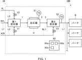
- FIG. 1 is a schematic diagram of a combustion facility including a fuel preheater according to a first embodiment.
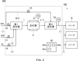
- FIG. 2 is a schematic diagram of a combustion facility including a fuel preheater according to a second embodiment.
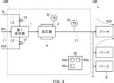
- FIG. 3 is a schematic diagram of a combustion facility including a fuel preheater according to a third embodiment.
- FIG. 1 is a schematic diagram of a combustion equipment 100 including a fuel preheater 10 according to the first embodiment.
- the fuel preheater 10 is provided in a fuel supply line L1 connected to the combustion equipment 100.
- Ammonia-containing gas flows through the fuel supply line L1.
- the combustion equipment 100 can be a boiler, an industrial furnace, a combustion furnace, or the like.
- the combustion equipment 100 is not limited to these, and can be various types of equipment that uses ammonia as fuel.
- the combustion equipment 100 may also be an existing facility. In another embodiment, the combustion equipment 100 may be a newly constructed facility.
- the combustion equipment 100 includes one or more burners B.
- Burner B burns a fuel containing ammonia.
- burner B may burn a mixture of ammonia and other fuels such as pulverized coal. Burner B may also burn only ammonia. Burner B may also burn a fuel that does not contain ammonia, if necessary.
- the fuel preheater 10 includes a first mixer 1, a reactor 2, a second mixer 3, and a control device 90.
- the fuel preheater 10 may further include other components not shown.
- the first mixer 1 is provided in the fuel supply line L1.
- the first mixer 1 may be installed on an existing fuel supply line L1 connected to an existing combustion equipment 100.
- the first mixer 1 is a gas mixer.
- the fuel supply line L1 supplies ammonia to the first mixer 1.
- the fuel supply line L1 supplies gaseous ammonia to the first mixer 1.
- An oxidizer supply line L2 is connected to the first mixer 1.
- the oxidizer supply line L2 supplies an oxidizer (e.g., air) to the first mixer 1.
- a valve (first valve) V1 is provided in the oxidizer supply line L2.
- the valve V1 is connected to the control device 90 via wired or wireless communication and is controlled by the control device 90.
- the control device 90 adjusts the flow rate of the oxidizer supplied to the first mixer 1 by controlling the opening degree of the valve V1.
- the first mixer 1 mixes the ammonia flowing through the fuel supply line L1 with the oxidizer supplied from the oxidizer supply line L2 to generate a mixed gas containing ammonia and the oxidizer.
- the mixed gas flows through the fuel supply line L1 and is supplied to the reactor 2.
- a nitrogen supply line L3 is connected to the first mixer 1.
- the nitrogen supply line L3 supplies nitrogen to the first mixer 1.
- a valve V2 is provided on the nitrogen supply line L3.
- the valve V2 is connected to the control device 90 via wired or wireless communication and is controlled by the control device 90.
- the control device 90 adjusts the flow rate of nitrogen supplied to the first mixer 1 by controlling the opening degree of the valve V2.
- the reactor 2 is provided downstream of the first mixer 1 in the fuel supply line L1. Similar to the first mixer 1, the reactor 2 may be installed on an existing fuel supply line L1 connected to an existing combustion facility 100.
- the reactor 2 receives the mixed gas from the first mixer 1.
- the reactor 2 includes a catalyst that promotes the reaction of ammonia to cause an exothermic reaction. Specifically, the catalyst promotes the reaction of at least a portion of the ammonia in the mixed gas supplied from the first mixer 1, causing catalytic combustion.
- the mixed gas is heated by the catalytic combustion. The heated mixed gas flows through the fuel supply line L1 and is supplied to the second mixer 3.
- the catalyst includes a transition element (which may also be referred to as a transition metal).
- the catalyst may include a precious metal such as Ru.
- the catalyst may include a non-precious metal such as Fe, Co, or Ni among the transition elements.
- the non-precious metal may exhibit high activity when combined with a specific support.
- a specific support for example, an oxide such as Al 2 O 3 or SiO 2 may be used. Also, if necessary, a support capable of suppressing sintering such as CeO 2 may be used.
- the reactor 2 is provided with a temperature sensor S1.
- the temperature sensor S1 is configured to measure the temperature of the catalyst.
- the temperature sensor S1 is connected to the control device 90 so as to be able to communicate with the control device 90 via wire or wirelessly, and transmits the measurement data to the control device 90.
- the reactor 2 is provided with a heating means H.
- the heating means H heats the catalyst.
- the heating means H may include an electric heater.
- the heating means H may include a first heat exchanger that heats the catalyst with exhaust gas from the combustion equipment 100.
- the heating means H may include a second heat exchanger that heats the catalyst with steam extracted from the combustion equipment 100.
- the heating means H is connected to the control device 90 so as to be able to communicate with it via wire or wirelessly, and is controlled by the control device 90.
- the control device 90 starts the operation of the heating means H and heats the catalyst until the temperature measured by the temperature sensor S1 reaches the temperature at which the catalyst starts to become active (e.g., 400°C).
- the control device 90 stops the operation of the heating means H. From this point on, the catalyst is maintained at a sufficient temperature by catalytic combustion.
- the second mixer 3 is provided downstream of the reactor 2 in the fuel supply line L1. Similar to the first mixer 1 and the reactor 2, the second mixer 3 may be installed on an existing fuel supply line L1 connected to an existing combustion facility 100. For example, the second mixer 3 is a gas mixer. The second mixer 3 receives the heated mixed gas from the reactor 2.
- the second mixer 3 is connected to the oxidant supply line L2 by a bypass line (first bypass line) BL1.
- the bypass line BL1 connects the oxidant supply line L2 directly to the second mixer 3 without passing through the first mixer 1 and the reactor 2. Therefore, at least a portion of the oxidant flowing through the oxidant supply line L2 is supplied to the first mixer 1, and the remainder of the oxidant is supplied to the second mixer 3.
- a valve V3 is provided in the bypass line BL1.
- the valve V3 is connected to the control device 90 via wired or wireless communication and is controlled by the control device 90.
- the control device 90 adjusts the flow rate of the oxidizer supplied to the second mixer 3 by controlling the opening degree of the valve V3.
- the second mixer 3 further mixes the mixed gas flowing through the fuel supply line L1 with the oxidizer supplied from the bypass line BL1.
- the mixed gas flows through the fuel supply line L1 and is supplied to the burner B as fuel (premixed combustion method).
- the burner B may be of a diffusion combustion type.
- a temperature sensor S2 is provided in the fuel supply line L1 downstream of the reactor 2, specifically, in this embodiment, downstream of the second mixer 3.
- the temperature sensor S2 is configured to measure the temperature of the mixed gas flowing through the fuel supply line L1.
- the temperature sensor S2 is connected to the control device 90 so as to be able to communicate with the control device 90 via wire or wirelessly, and transmits the measurement data to the control device 90.
- the fuel supply line L1 branches into multiple lines downstream of the temperature sensor S2 and is connected to each of the multiple burners B.
- the control device 90 controls the fuel preheater 10.
- the control device 90 may also control at least some of the components of the combustion equipment 100.
- the combustion equipment 100 may be equipped with a main control device (not shown), and the control device 90 may communicate with the main control device.
- the control device 90 includes components such as a processor 90a, a storage device 90b, and a connector 90c, and these components are connected to each other via a bus.
- the processor 90a includes a CPU (Central Processing Unit), etc.
- the storage device 90b includes a hard disk, a ROM in which programs and the like are stored, and a RAM as a work area, etc.
- the control device 90 is connected to each component of the fuel preheater 10 via the connector 90c so as to be able to communicate with each component via a wired or wireless connection.
- the control device 90 may further include other components, such as a display device such as a liquid crystal display or a touch panel, and an input device such as a keyboard, a button, or a touch panel.
- the operation of the control device 90 may be realized by having the processor 90a execute a program stored in the storage device 90b.
- the catalyst can cause both reactions (1) and (2).
- the control device 90 may control the valve V1 to adjust the amount of oxidant allocated from the oxidant supply line L2 to the first mixer 1, i.e., the amount of oxidant supplied to the reactor 2, so that most of the oxidant in the mixed gas supplied to the reactor 2 is used by the exothermic reaction (2).
- the control device 90 may also control the valve V3 as necessary.
- controller 90 increases the flow rate of oxidant supplied to reactor 2 from oxidant supply line L2. In contrast, for example, if the amount of oxidant supplied to reactor 2 is excessive, controller 90 reduces the flow rate of oxidant supplied to reactor 2 from oxidant supply line L2.
- the oxidizer required for combustion in burner B is supplied from oxidizer supply line L2 via bypass line BL1 to second mixer 3, where it is mixed with the heated mixed gas.
- the control device 90 controls valve V3 to adjust the amount of oxidizer allocated from oxidizer supply line L2 to bypass line BL1, i.e., the amount of oxidizer supplied to second mixer 3.
- the control device 90 may also control valve V1 as necessary.
- the controller 90 may increase the flow rate of oxidizer supplied from the oxidizer supply line L2 to the second mixer 3. In contrast, for example, if the amount of oxidizer supplied to burner B is excessive, the controller 90 may reduce the flow rate of oxidizer supplied from the oxidizer supply line L2 to the second mixer 3.
- the control device 90 also stores a predetermined threshold value in the memory device 90b.
- This threshold value is associated with the temperature at which the material forming the fuel supply line L1 starts to nitride.
- the fuel supply line L1 may be formed from a steel such as stainless steel. It is known that many steels become nitrided when exposed to an environment containing ammonia at approximately 400°C to 600°C. Therefore, most steels will not nitride even when exposed to an environment containing ammonia as long as the temperature is below the above range.
- the threshold value may be, for example, 400°C.
- the threshold value may also be determined by testing. For example, a test piece made of the same material as that forming the fuel supply line L1 is placed in an environment simulating the inside of the fuel supply line L1. The environment is maintained for a predetermined period of time (for example, one month, multiple months, one year, or multiple years). The nitrided layer depth of the test piece is then measured, and the nitriding rate per year (mm/year) is calculated. This test is performed at multiple temperatures. For example, the temperature at which the nitriding rate is less than a predetermined value may be determined as the threshold value (for example, less than 1 mm/year). For example, the nitrided layer depth may be measured by the "measurement method by hardness test” or “measurement method by metal structure test” of the "method of measuring the nitrided layer depth of steel" defined in JIS G0562.
- the control device 90 may adjust the flow rate of the oxidant supplied to the reactor 2 and the flow rate of the oxidant supplied to the second mixer 3 by controlling at least one of the valves V1 and V3 so that the temperature of the mixed gas measured by the temperature sensor S2 is below a threshold value.
- control device 90 may open valve V2 and add nitrogen to the mixed gas as an emergency coolant.
- the fuel supply line L1 may be provided with a valve (not shown) for adjusting the flow rate of ammonia supplied to the first mixer 1.
- Each of the lines L1, L2, and L3 may be provided with a pump (not shown) for sending fluid.
- These valves and pumps may be connected to the control device 90 in a wired or wireless manner so as to be able to communicate with each other, and may be controlled by the control device 90.
- the control device 90 starts the operation of the heating means H.
- the catalyst is heated until the temperature measured by the temperature sensor S1 reaches the temperature at which the catalyst starts to become active.
- the control device 90 controls the valve V1 to start supplying the oxidizer to the first mixer 1.
- the first mixer 1 also receives ammonia from the fuel supply line L1.
- the first mixer 1 mixes the ammonia and the oxidizer to generate a mixed gas.
- the mixed gas is supplied to the reactor 2 by the fuel supply line L1.
- the control device 90 also stops the operation of the heating means H. From this point on, the catalyst is maintained at a sufficient temperature by catalytic combustion.
- At least a portion of the oxidant in the mixed gas reacts with ammonia on the catalyst in the reactor 2, causing catalytic combustion. This heats the mixed gas.
- the heated mixed gas is supplied to the second mixer 3 by the fuel supply line L1.
- the control device 90 controls the valve V3 to start supplying the oxidizer required for combustion in the burner B to the second mixer 3.
- the second mixer 3 also receives heated mixed gas from the fuel supply line L1.
- the second mixer 3 further mixes the ammonia and the oxidizer.
- the heated mixed gas is supplied to the multiple burners B as premixed fuel via the fuel supply line L1.
- the fuel preheater 10 as described above includes a first mixer 1 provided in a fuel supply line L1 connected to a combustion facility 100 that burns a fuel containing ammonia, and a reactor 2 provided downstream of the first mixer 1 in the fuel supply line L1.
- the fuel supply line L1 supplies ammonia to the first mixer 1.
- the first mixer 1 is connected to an oxidizer supply line L2 that supplies an oxidizer, and mixes the ammonia flowing through the fuel supply line L1 with the oxidizer from the oxidizer supply line L2 to generate a mixed gas.
- the reactor 2 includes a catalyst that promotes the reaction of ammonia to cause an exothermic reaction.
- the catalyst causes an exothermic reaction by at least a portion of the ammonia in the mixed gas supplied from the first mixer 1, and heats the mixed gas.
- the mixed gas containing ammonia and heated by the exothermic reaction in the reactor 2 can be supplied to the combustion facility 100. Since the mixed gas is heated by the exothermic reaction, the ammonia in the mixed gas is also heated, and the combustion speed of the ammonia is increased. Therefore, fuel can be supplied to the combustion equipment 100 with an increased combustion rate.
- the fuel preheater 10 includes a second mixer 3 provided downstream of the reactor 2 in the fuel supply line L1.
- the second mixer 3 is connected to the oxidizer supply line L2 by a bypass line BL1, and mixes the mixed gas supplied from the reactor 2 with the oxidizer supplied from the bypass line BL1.
- the fuel preheater 10 includes a valve V1 provided in the oxidizer supply line L2 to adjust the flow rate of the oxidizer, a temperature sensor S2 provided in the fuel supply line L1 downstream of the reactor 2 to measure the temperature of the mixed gas, and a control device 90 communicatively connected to the valve V1 and the temperature sensor S2.
- the control device 90 stores a predetermined threshold value associated with the temperature at which the material forming the fuel supply line L1 starts to be nitriding.
- the control device 90 controls the valve V1 to adjust the flow rate of the oxidizer supplied to the first mixer 1 so that the temperature of the mixed gas measured by the temperature sensor S2 is below the threshold value.
- the reactor 2 also includes a heating means H for heating the catalyst, which may include a heater.
- a heating means H for heating the catalyst which may include a heater.
- the heating means H may include a first heat exchanger that heats the catalyst with exhaust gas from the combustion equipment 100.
- the catalyst can be quickly heated to a temperature at which the catalyst begins to become active, and the exhaust gas can be reused.
- the heating means H may include a second heat exchanger that heats the catalyst with steam extracted from the combustion equipment 100.
- the catalyst can be quickly heated to a temperature at which the catalyst begins to become active.
- the fuel preheater 10 supplies the mixed gas to multiple burners B of the combustion equipment 100. With this configuration, there is no need to provide a fuel preheater for each burner B.
- the exothermic reaction in the catalyst of reactor 2 is catalytic combustion. With this configuration, flameless combustion mainly occurs on the surface of reactor 2, making it very safe.
- the air ratio in reactor 2 can be changed and the temperature of the mixed gas can be controlled.
- the ignition ability and combustion stability of the flame-retardant ammonia in burner B can be improved.
- the fuel preheater 10 as described above can be installed in an existing combustion facility 100.
- the method of installing the fuel preheater 10 in the combustion facility 100 according to the present embodiment includes preparing a first mixer 1 configured to mix ammonia and an oxidizer, preparing a reactor 2 including a catalyst that causes an exothermic reaction by ammonia, and installing the first mixer 1 in a fuel supply line L1 connected to the combustion facility 100 that burns a fuel including ammonia.
- the fuel supply line L1 supplies ammonia to the first mixer 1.
- the method according to the present embodiment also includes connecting an oxidizer supply line L2 that supplies an oxidizer to the first mixer 1.
- the first mixer 1 mixes the ammonia flowing through the fuel supply line L1 with the oxidizer from the oxidizer supply line L2 to generate a mixed gas.
- the method according to the present embodiment also includes installing a reactor 2 downstream of the first mixer 1 in the fuel supply line L1.
- the catalyst causes an exothermic reaction by at least a portion of the ammonia in the mixed gas supplied from the first mixer 1, and heats the mixed gas. This configuration makes it possible to supply fuel at an increased combustion rate to existing combustion equipment 100 without major construction work.
- fuel preheaters 10, 10A, and 10B include components surrounded by dashed lines. Therefore, the method of installing fuel preheater 10, 10A, or 10B to combustion equipment 100 according to the present disclosure may further include installing components other than first mixer 1 and reactor 2 within the dashed lines to existing fuel supply line L1.
- FIG. 2 is a schematic diagram of a combustion equipment 100 including a fuel preheater 10A according to the second embodiment.
- the fuel preheater 10A differs from the fuel preheater 10 according to the first embodiment in that it includes an ammonia bypass line (second bypass line) BL2 and a third mixer 4 instead of the oxidizer bypass line BL1 and the second mixer 3.
- the fuel preheater 10A may be the same as the fuel preheater 10.
- the third mixer 4 is provided downstream of the reactor 2 in the fuel supply line L1.
- the third mixer 4 may be installed on an existing fuel supply line L1 connected to an existing combustion equipment 100.
- the third mixer 4 is a gas mixer.
- the third mixer 4 receives the heated mixed gas from the reactor 2.
- the third mixer 4 is connected to the fuel supply line L1 at a position upstream of the first mixer 1 by the bypass line BL2.
- the bypass line BL2 connects the fuel supply line L1 directly to the third mixer 4 without passing through the first mixer 1 and the reactor 2. Therefore, at least a portion of the ammonia flowing through the fuel supply line L1 is supplied to the first mixer 1, and the remainder of the ammonia is supplied to the third mixer 4.
- a valve (second valve) V4 is provided in the fuel supply line L1 between the connection to the bypass line BL2 and the first mixer 1.
- the valve V4 is connected to the control device 90 so as to be able to communicate with it via wire or wirelessly, and is controlled by the control device 90.
- the control device 90 adjusts the flow rate of ammonia supplied to the first mixer 1 by controlling the opening degree of the valve V4.
- a valve V5 is provided in the bypass line BL2.
- the valve V5 is connected to the control device 90 via wired or wireless communication and is controlled by the control device 90.
- the control device 90 adjusts the flow rate of ammonia supplied to the third mixer 4 by controlling the opening degree of the valve V5.
- the third mixer 4 further mixes the mixed gas flowing through the fuel supply line L1 with ammonia supplied from the bypass line BL2.
- the mixed gas flows through the fuel supply line L1 and is supplied to the burner B as fuel.
- control device 90 may control the valve V4 to adjust the flow rate of ammonia allocated from the fuel supply line L1 to the first mixer 1, i.e., the flow rate of ammonia supplied to the reactor 2, so that most of the ammonia in the mixed gas supplied to the reactor 2 is used by the exothermic reaction (2).
- the control device 90 may also control the valve V5 as necessary.
- the controller 90 may increase the flow rate of ammonia supplied to the reactor 2 from the fuel supply line L1. In contrast, for example, if the reactor 2 is overheating the mixed gas, the controller 90 may reduce the flow rate of oxidant supplied to the reactor 2 from the fuel supply line L1.
- the ammonia required for combustion in burner B is supplied from fuel supply line L1 through bypass line BL2 to third mixer 4, where it is mixed with the heated mixed gas.
- the control device 90 controls valve V5 to adjust the amount of ammonia allocated from fuel supply line L1 to bypass line BL2, i.e., the amount of ammonia supplied to third mixer 4.
- the control device 90 may also control valve V4 as necessary.
- the controller 90 may increase the flow rate of ammonia supplied from fuel supply line L1 to the third mixer 4. In contrast, for example, if the amount of ammonia supplied to burner B is excessive, the controller 90 may reduce the flow rate of ammonia supplied from fuel supply line L1 to the third mixer 4.
- control device 90 may control at least one of the valves V4 and V5 to adjust the flow rate of ammonia supplied to the reactor 2 and the flow rate of ammonia supplied to the third mixer 4 so that the temperature of the mixed gas measured by the temperature sensor S2 is less than a threshold value (e.g., 400°C).
- a threshold value e.g. 400°C
- the fuel preheater 10A as described above has substantially the same effects as the fuel preheater 10 according to the first embodiment.
- the fuel preheater 10A also includes a third mixer 4 that is provided downstream of the reactor 2 in the fuel supply line L1.
- the third mixer 4 is connected to the fuel supply line L1 at a position upstream of the first mixer 1 by a bypass line BL2, and mixes the mixed gas supplied from the reactor 2 with the ammonia supplied from the bypass line BL2. With this configuration, the amount of ammonia supplied from the fuel supply line L1 to the reactor 2 can be adjusted more precisely.
- the fuel preheater 10A includes a valve V4 provided upstream of the first mixer 1 in the fuel supply line L1 to adjust the flow rate of ammonia supplied to the first mixer 1, a temperature sensor S2 provided downstream of the reactor 2 in the fuel supply line L1 to measure the temperature of the mixed gas, and a control device 90 communicatively connected to the valve V4 and the temperature sensor S2.
- the control device 90 stores a predetermined threshold value associated with the temperature at which the material forming the fuel supply line L1 starts to be nitriding.
- the control device 90 controls the valve V4 to adjust the flow rate of ammonia supplied to the first mixer 1 so that the temperature of the mixed gas measured by the temperature sensor S2 is less than the threshold value.
- FIG. 3 is a schematic diagram of a combustion equipment 100 including a fuel preheater 10B according to a third embodiment.
- the fuel preheater 10B differs from the fuel preheater 10 according to the first embodiment in that it does not include a bypass line BL1 and a second mixer 3. In other respects, the fuel preheater 10B may be the same as the fuel preheater 10.
- each burner B of the combustion equipment 100 is of a diffusion combustion type. Air necessary for diffusion combustion is supplied to each burner B.
- the combustion equipment 100 may include components (not shown) such as an air register and a damper for adjusting the amount of air to each burner B. Note that in FIG. 3, air is shown only for the top burner B.
- control device 90 controls the valve V1 to adjust the amount of oxidant supplied from the oxidant supply line L2 through the first mixer 1 to the reactor 2 so that most of the oxidant in the mixed gas supplied to the reactor 2 is used by the exothermic reaction (2).
- control device 90 controls the valve V1 to adjust the flow rate of the oxidant supplied to the reactor 2 so that the temperature of the mixed gas measured by the temperature sensor S2 is less than a threshold value (e.g., 400°C).
- a threshold value e.g. 400°C
- the fuel preheater 10B described above has substantially the same effects as the fuel preheater 10 according to the first embodiment.
- the present disclosure can facilitate the use of ammonia leading to reduced CO2 emissions, thereby contributing, for example, to Sustainable Development Goal (SDG) Goal 7 "Ensure access to affordable, reliable, sustainable and modern energy” and Goal 13 "Take urgent action to combat climate change and its impacts.”
- SDG Sustainable Development Goal
Landscapes
- Engineering & Computer Science (AREA)
- Chemical & Material Sciences (AREA)
- Combustion & Propulsion (AREA)
- Mechanical Engineering (AREA)
- General Engineering & Computer Science (AREA)
- Chemical Kinetics & Catalysis (AREA)
- Organic Chemistry (AREA)
- Health & Medical Sciences (AREA)
- General Health & Medical Sciences (AREA)
- Inorganic Chemistry (AREA)
- Feeding And Controlling Fuel (AREA)
Abstract
Description
本開示は、燃料予熱器に関する。本出願は2023年6月14日に提出された日本特許出願第2023-097818号に基づく優先権の利益を主張するものであり、その内容は本出願に援用される。 This disclosure relates to a fuel preheater. This application claims the benefit of priority to Japanese Patent Application No. 2023-097818, filed on June 14, 2023, the contents of which are incorporated herein by reference.
燃焼設備では、燃焼を促進するために触媒が使用される場合がある。例えば、特許文献1は、触媒式無炎燃焼装置を開示する。この装置では、空気および天然ガスの混合ガスが、燃焼室に充填された触媒上で燃焼される。
In combustion equipment, catalysts may be used to promote combustion. For example,
また、特許文献2は、触媒燃焼バーナを開示する。このバーナでは、天然ガスまたは都市ガス等の気体燃料および空気の混合ガスが、触媒上で燃焼される。
また、特許文献3は、ガスタービンのバーナ部分を開示する。このガスタービンでは、天然ガスおよび空気の混合ガスが、触媒によって酸化され、さらに、パイロット火炎および主火炎で燃焼される。
アンモニアは、CO2を放出しない燃料として知られている。しかしながら、アンモニアの燃焼速度は、天然ガス等の他の燃焼速度よりも遅い。したがって、燃焼設備においてアンモニアを使用する場合、アンモニアの燃焼速度を高めることが望ましい。 Ammonia is known as a fuel that does not emit CO2 . However, the burning rate of ammonia is slower than other burning rates such as natural gas. Therefore, when using ammonia in a combustion facility, it is desirable to increase the burning rate of ammonia.
本開示は、燃焼設備においてアンモニアが燃料として使用される場合に、燃焼速度を高めた状態で燃料を燃焼設備に供給することができる、燃料予熱器を提供することを目的とする。また、本開示は、このような燃料予熱器を燃焼設備へ設置するための方法を提供することを目的とする。 The present disclosure aims to provide a fuel preheater that can supply fuel to a combustion facility with an increased combustion rate when ammonia is used as fuel in the combustion facility. The present disclosure also aims to provide a method for installing such a fuel preheater in the combustion facility.
本開示の一態様に係る燃料予熱器は、アンモニアを含む燃料を燃焼する燃焼設備に接続された燃料供給ラインに設けられる第1混合器であって、燃料供給ラインは、当該第1混合器にアンモニアを供給し、当該第1混合器は、酸化剤を供給する酸化剤供給ラインに接続され、燃料供給ラインを流れるアンモニアと、酸化剤供給ラインからの酸化剤とを混合して、混合ガスを生成する、第1混合器と、燃料供給ラインにおいて第1混合器の下流に設けられる反応器であって、当該反応器は、アンモニアの反応を促進して発熱反応を引き起こす触媒を含み、触媒は、第1混合器から供給される混合ガス中のアンモニアの少なくとも一部によって発熱反応を引き起こし、混合ガスを加熱する、反応器と、を含む。 A fuel preheater according to one embodiment of the present disclosure includes a first mixer provided in a fuel supply line connected to a combustion facility that combusts a fuel containing ammonia, the fuel supply line supplies ammonia to the first mixer, the first mixer is connected to an oxidizer supply line that supplies an oxidizer, and mixes the ammonia flowing through the fuel supply line with the oxidizer from the oxidizer supply line to generate a mixed gas, and a reactor provided downstream of the first mixer in the fuel supply line, the reactor including a catalyst that promotes the reaction of ammonia to cause an exothermic reaction, the catalyst causing an exothermic reaction by at least a portion of the ammonia in the mixed gas supplied from the first mixer, and heating the mixed gas.
燃料予熱器は、燃料供給ラインにおいて反応器の下流に設けられる第2混合器であって、当該第2混合器は、第1バイパスラインによって酸化剤供給ラインに接続され、反応器から供給される混合ガスと、第1バイパスラインから供給される酸化剤とを混合する、第2混合器を備えてもよい。 The fuel preheater may include a second mixer that is provided downstream of the reactor in the fuel supply line, the second mixer being connected to the oxidizer supply line by a first bypass line, and mixing the mixed gas supplied from the reactor with the oxidizer supplied from the first bypass line.
燃料予熱器は、酸化剤供給ラインに設けられ、第1混合器に供給される酸化剤の流量を調整する第1バルブと、燃料供給ラインにおいて反応器の下流に設けられ、混合ガスの温度を測定する温度センサと、第1バルブおよび温度センサと通信可能に接続される制御装置であって、当該制御装置は、燃料供給ラインを形成する材料が窒化を開始する温度に関連付けられる所定の閾値を記憶し、当該制御装置は、温度センサによって測定される混合ガスの温度が閾値未満になるように、第1バルブを制御して第1混合器に供給される酸化剤の流量を調整する、制御装置と、を備えてもよい。 The fuel preheater may include a first valve provided in the oxidizer supply line to adjust the flow rate of the oxidizer supplied to the first mixer, a temperature sensor provided in the fuel supply line downstream of the reactor to measure the temperature of the mixed gas, and a control device communicatively connected to the first valve and the temperature sensor, the control device storing a predetermined threshold value associated with the temperature at which the material forming the fuel supply line begins to nitrid, and the control device controlling the first valve to adjust the flow rate of the oxidizer supplied to the first mixer so that the temperature of the mixed gas measured by the temperature sensor is below the threshold value.
反応器は、触媒を加熱するための加熱手段を含んでもよく、加熱手段は、ヒータを含んでもよい。 The reactor may include a heating means for heating the catalyst, and the heating means may include a heater.
代替的にまたは追加的に、加熱手段は、燃焼設備からの排ガスによって触媒を加熱する第1熱交換器を含んでもよい。 Alternatively or additionally, the heating means may include a first heat exchanger for heating the catalyst with exhaust gas from the combustion facility.
代替的にまたは追加的に、加熱手段は、燃焼設備から抽気された蒸気によって触媒を加熱する第2熱交換器を含んでもよい。 Alternatively or additionally, the heating means may include a second heat exchanger for heating the catalyst with steam extracted from the combustion facility.
燃料予熱器は、燃料供給ラインにおいて反応器の下流に設けられる第3混合器であって、当該第3混合器は、第2バイパスラインによって、燃料供給ラインにおいて第1混合器よりも上流の位置に接続され、反応器から供給される混合ガスと、第2バイパスラインから供給されるアンモニアとを混合する、第3混合器を備えてもよい。 The fuel preheater may include a third mixer that is provided downstream of the reactor in the fuel supply line, and that is connected to a position upstream of the first mixer in the fuel supply line by a second bypass line, and that mixes the mixed gas supplied from the reactor with ammonia supplied from the second bypass line.
燃料予熱器は、燃料供給ラインにおいて第1混合器の上流に設けられ、第1混合器に供給されるアンモニアの流量を調整する第2バルブと、燃料供給ラインにおいて反応器の下流に設けられ、混合ガスの温度を測定する温度センサと、第2バルブおよび温度センサと通信可能に接続される制御装置であって、当該制御装置は、燃料供給ラインを形成する材料が窒化を開始する温度に関連付けられる所定の閾値を記憶し、当該制御装置は、温度センサによって測定される混合ガスの温度が閾値未満になるように、第2バルブを制御して第1混合器に供給されるアンモニアの流量を調整する、制御装置と、を備えてもよい。 The fuel preheater may include a second valve provided in the fuel supply line upstream of the first mixer and regulating the flow rate of ammonia supplied to the first mixer, a temperature sensor provided in the fuel supply line downstream of the reactor and measuring the temperature of the mixed gas, and a control device communicatively connected to the second valve and the temperature sensor, the control device storing a predetermined threshold value associated with the temperature at which the material forming the fuel supply line begins to nitrid, and the control device controlling the second valve to regulate the flow rate of ammonia supplied to the first mixer so that the temperature of the mixed gas measured by the temperature sensor is below the threshold value.
燃料予熱器は、燃焼設備の複数のバーナに混合ガスを供給してもよい。 The fuel preheater may supply the mixed gas to multiple burners of the combustion equipment.
反応器の触媒における発熱反応は、触媒燃焼であってもよい。 The exothermic reaction in the reactor catalyst may be catalytic combustion.
本開示の他の態様は、燃焼設備への燃料予熱器の取り付け方法であり、この方法は、アンモニアおよび酸化剤を混合するように構成された第1混合器を準備することと、アンモニアによる発熱反応を引き起こす触媒を含む反応器を準備することと、アンモニアを含む燃料を燃焼する燃焼設備に接続された燃料供給ラインに第1混合器を設置することであって、燃料供給ラインは、第1混合器にアンモニアを供給する、ことと、酸化剤を供給する酸化剤供給ラインを第1混合器に接続することであって、第1混合器は、燃料供給ラインを流れるアンモニアと、酸化剤供給ラインからの酸化剤とを混合して、混合ガスを生成する、ことと、燃料供給ラインにおいて第1混合器の下流に反応器を設置することであって、触媒は、第1混合器から供給される混合ガス中のアンモニアの少なくとも一部によって発熱反応を引き起こし、混合ガスを加熱する、ことと、を含む。 Another aspect of the present disclosure is a method of installing a fuel preheater in a combustion facility, the method including: preparing a first mixer configured to mix ammonia and an oxidizer; preparing a reactor including a catalyst that causes an exothermic reaction with ammonia; installing the first mixer in a fuel supply line connected to the combustion facility that burns a fuel including ammonia, the fuel supply line supplying ammonia to the first mixer; connecting an oxidizer supply line that supplies an oxidizer to the first mixer, the first mixer mixing the ammonia flowing through the fuel supply line with the oxidizer from the oxidizer supply line to generate a mixed gas; installing a reactor downstream of the first mixer in the fuel supply line, the catalyst causing an exothermic reaction with at least a portion of the ammonia in the mixed gas supplied from the first mixer to heat the mixed gas.
本開示によれば、燃焼設備においてアンモニアが燃料として使用される場合に、燃焼速度を高めた状態で燃料を燃焼設備に供給することができる。 According to the present disclosure, when ammonia is used as fuel in a combustion facility, the fuel can be supplied to the combustion facility with an increased combustion rate.
以下に添付図面を参照しながら、本開示の実施形態について詳細に説明する。かかる実施形態に示す具体的な寸法、材料および数値等は、理解を容易とするための例示にすぎず、特に断る場合を除き、本開示を限定するものではない。なお、本明細書および図面において、実質的に同一の機能、構成を有する要素については、同一の符号を付することにより重複説明を省略し、また本開示に直接関係のない要素は図示を省略する。 Below, an embodiment of the present disclosure will be described in detail with reference to the attached drawings. Specific dimensions, materials, values, etc. shown in such embodiments are merely examples for ease of understanding, and do not limit the present disclosure unless otherwise specified. In this specification and drawings, elements having substantially the same functions and configurations are designated by the same reference numerals to avoid duplicated explanations, and elements not directly related to the present disclosure are not illustrated.
図1は、第1実施形態に係る燃料予熱器10を備える燃焼設備100の概略図である。燃料予熱器10は、燃焼設備100に接続された燃料供給ラインL1に設けられる。燃料供給ラインL1には、アンモニアを含むガスが流れる。例えば、燃焼設備100は、ボイラ、工業炉または燃焼炉等であることができる。燃焼設備100はこれらに限定されず、アンモニアを燃料として使用する様々な設備であることができる。また、燃焼設備100は、既存の設備であってもよい。他の実施形態では、燃焼設備100は、新設の設備であってもよい。例えば、燃焼設備100は、1つまたは複数のバーナBを含む。
FIG. 1 is a schematic diagram of a
バーナBは、アンモニアを含む燃料を燃焼させる。例えば、バーナBは、アンモニアおよび微粉炭等の他の燃料の混合燃料を燃焼させてもよい。また、バーナBは、アンモニアのみを燃焼させてもよい。また、バーナBは、必要に応じて、アンモニアを含まない燃料を燃焼させてもよい。 Burner B burns a fuel containing ammonia. For example, burner B may burn a mixture of ammonia and other fuels such as pulverized coal. Burner B may also burn only ammonia. Burner B may also burn a fuel that does not contain ammonia, if necessary.
例えば、燃料予熱器10は、第1混合器1と、反応器2と、第2混合器3と、制御装置90と、を含む。燃料予熱器10は、不図示の他の構成要素をさらに含んでもよい。
For example, the
第1混合器1は、燃料供給ラインL1に設けられる。例えば、第1混合器1は、既存の燃焼設備100に接続された、既存の燃料供給ラインL1に対して設置されてもよい。例えば、第1混合器1は、ガス混合器である。燃料供給ラインL1は、第1混合器1にアンモニアを供給する。例えば、燃料供給ラインL1は、第1混合器1に気体アンモニアを供給する。
The
第1混合器1には、酸化剤供給ラインL2が接続される。酸化剤供給ラインL2は、第1混合器1に酸化剤(例えば、空気)を供給する。
An oxidizer supply line L2 is connected to the
酸化剤供給ラインL2には、バルブ(第1バルブ)V1が設けられる。バルブV1は、制御装置90と有線または無線で通信可能に接続され、制御装置90によって制御される。制御装置90は、バルブV1の開度を制御することによって、第1混合器1に供給される酸化剤の流量を調整する。
A valve (first valve) V1 is provided in the oxidizer supply line L2. The valve V1 is connected to the
第1混合器1は、燃料供給ラインL1を流れるアンモニアと、酸化剤供給ラインL2から供給される酸化剤とを混合して、アンモニアおよび酸化剤を含む混合ガスを生成する。混合ガスは、燃料供給ラインL1を流れて、反応器2に供給される。
The
第1混合器1には、窒素供給ラインL3が接続される。窒素供給ラインL3は、第1混合器1に窒素を供給する。
A nitrogen supply line L3 is connected to the
窒素供給ラインL3には、バルブV2が設けられる。バルブV2は、制御装置90と有線または無線で通信可能に接続され、制御装置90によって制御される。制御装置90は、バルブV2の開度を制御することによって、第1混合器1に供給される窒素の流量を調整する。
A valve V2 is provided on the nitrogen supply line L3. The valve V2 is connected to the
反応器2は、燃料供給ラインL1において第1混合器1の下流に設けられる。第1混合器1と同様に、反応器2は、既存の燃焼設備100に接続された、既存の燃料供給ラインL1に対して設置されてもよい。反応器2は、第1混合器1から混合ガスを受け取る。反応器2は、アンモニアの反応を促進して発熱反応を引き起こす触媒を含む。具体的には、触媒は、第1混合器1から供給される混合ガス中のアンモニアの少なくとも一部の反応を促進し、触媒燃焼を引き起こす。混合ガスは、触媒燃焼によって加熱される。加熱された混合ガスは、燃料供給ラインL1を流れて、第2混合器3に供給される。
The
例えば、触媒は、遷移元素(遷移金属とも称され得る)を含む。例えば、触媒は、Ru等の貴金属を含んでもよい。また、例えば、触媒は、遷移元素のうち、Fe、Co、Ni等の非貴金属を含んでもよい。非貴金属は、特定の担体と組み合わされる場合に、高い活性を示す場合がある。担体としては、例えば、Al2O3またはSiO2等の酸化物が使用されてもよい。また、必要に応じて、CeO2等のシンタリングを抑制することができる担体が使用されてもよい。 For example, the catalyst includes a transition element (which may also be referred to as a transition metal). For example, the catalyst may include a precious metal such as Ru. Also, for example, the catalyst may include a non-precious metal such as Fe, Co, or Ni among the transition elements. The non-precious metal may exhibit high activity when combined with a specific support. As the support, for example, an oxide such as Al 2 O 3 or SiO 2 may be used. Also, if necessary, a support capable of suppressing sintering such as CeO 2 may be used.
反応器2には、温度センサS1が設けられる。温度センサS1は、触媒の温度を測定するように構成される。温度センサS1は、制御装置90と有線または無線で通信可能に接続され、測定データを制御装置90に送信する。
The
反応器2には、加熱手段Hが設けられる。加熱手段Hは、触媒を加熱する。例えば、加熱手段Hは、電気ヒータを含んでもよい。代替的にまたは追加的に、加熱手段Hは、燃焼設備100からの排ガスによって触媒を加熱する第1熱交換器を含んでもよい。さらに代替的にまたは追加的に、燃焼設備100がボイラを含む場合には、加熱手段Hは、燃焼設備100から抽気された蒸気によって触媒を加熱する第2熱交換器を含んでもよい。加熱手段Hは、制御装置90と有線または無線で通信可能に接続され、制御装置90によって制御される。
The
例えば、燃料予熱器10が運転を開始するときに、制御装置90は、加熱手段Hの動作を開始し、温度センサS1によって測定される温度が、触媒が活性を開始する温度(例えば、400℃)に達するまで、触媒を加熱する。温度センサS1によって測定される温度が、触媒が活性を開始する温度に達すると、制御装置90は、加熱手段Hの動作を停止にする。これ以降は、触媒は、触媒燃焼によって十分な温度に維持される。
For example, when the
第2混合器3は、燃料供給ラインL1において反応器2の下流に設けられる。第1混合器1および反応器2と同様に、第2混合器3は、既存の燃焼設備100に接続された、既存の燃料供給ラインL1に対して設置されてもよい。例えば、第2混合器3は、ガス混合器である。第2混合器3は、反応器2から加熱された混合ガスを受け取る。
The
第2混合器3は、バイパスライン(第1バイパスライン)BL1によって、酸化剤供給ラインL2に接続される。バイパスラインBL1は、酸化剤供給ラインL2を、第1混合器1および反応器2を通すこと無く、直接的に第2混合器3に接続する。したがって、酸化剤供給ラインL2を流れる酸化剤の少なくとも一部は第1混合器1に供給され、酸化剤の残りは第2混合器3に供給される。
The
バイパスラインBL1には、バルブV3が設けられる。バルブV3は、制御装置90と有線または無線で通信可能に接続され、制御装置90によって制御される。制御装置90は、バルブV3の開度を制御することによって、第2混合器3に供給される酸化剤の流量を調整する。
A valve V3 is provided in the bypass line BL1. The valve V3 is connected to the
第2混合器3は、燃料供給ラインL1を流れる混合ガスと、バイパスラインBL1から供給される酸化剤とをさらに混合する。混合ガスは、燃料供給ラインL1を流れて、燃料としてバーナBに供給される(予混合燃焼方式)。他の実施形態では、バーナBは、拡散燃焼方式であってもよい。
The
燃料供給ラインL1において反応器2の下流の位置、具体的には、本実施形態では第2混合器3の下流の位置には、温度センサS2が設けられる。温度センサS2は、燃料供給ラインL1を流れる混合ガスの温度を測定するように構成される。温度センサS2は、制御装置90と有線または無線で通信可能に接続され、測定データを制御装置90に送信する。
A temperature sensor S2 is provided in the fuel supply line L1 downstream of the
燃料供給ラインL1は、温度センサS2の下流の位置で複数のラインに分岐され、複数のバーナBの各々に接続される。 The fuel supply line L1 branches into multiple lines downstream of the temperature sensor S2 and is connected to each of the multiple burners B.
制御装置90は、燃料予熱器10を制御する。また、制御装置90は、燃焼設備100の構成要素の少なくとも一部を制御してもよい。また、例えば、燃焼設備100は、不図示のメイン制御装置を備えてもよく、制御装置90は、メイン制御装置と通信してもよい。制御装置90は、例えば、プロセッサ90a、記憶装置90bおよびコネクタ90c等の構成要素を含み、これらの構成要素はバスを介して互いに接続される。例えば、プロセッサ90aは、CPU(Central Processing Unit)等を含む。例えば、記憶装置90bは、ハードディスク、プログラム等が格納されるROM、および、ワークエリアとしてのRAM等を含む。制御装置90は、コネクタ90cを介して燃料予熱器10の各構成要素と有線でまたは無線で通信可能に接続される。例えば、制御装置90は、液晶ディスプレイまたはタッチパネル等の表示装置、および、キーボード、ボタンまたはタッチパネル等の入力装置等、他の構成要素を更に含んでもよい。例えば、制御装置90の動作は、記憶装置90bに記憶されるプログラムをプロセッサ90aに実行することによって、実現されてもよい。
The
反応器2中の触媒は、アンモニアの反応を促進し、以下の反応(1)、(2)またはそれらの組み合わせを引き起こす。
(1)NH3→1.5H2+0.5N2 ΔH=45.4(kJ/mol)
(2)2NH3+1.5O2→N2+3H2O ΔH=-382.6(kJ/mol)
The catalyst in
(1) NH 3 → 1.5H 2 +0.5N 2 ΔH=45.4 (kJ/mol)
(2) 2NH 3 +1.5O 2 →N 2 +3H 2 O ΔH=-382.6 (kJ/mol)
例えば、本実施形態では、触媒は、反応(1)および(2)の双方を引き起こし得る。例えば、制御装置90は、反応器2に供給される混合ガス中の大部分の酸化剤が、発熱反応である反応(2)によって使用されるように、バルブV1を制御して、酸化剤供給ラインL2から第1混合器1に割り当てられる酸化剤の量、すなわち、反応器2に供給される酸化剤の量を調整してもよい。また、制御装置90は、必要に応じて、バルブV3を制御してもよい。
For example, in this embodiment, the catalyst can cause both reactions (1) and (2). For example, the
例えば、反応器2が触媒燃焼のためにより多くの酸化剤を必要とする場合には、制御装置90は、酸化剤供給ラインL2から反応器2に供給される酸化剤の流量を増加させる。対照的に、例えば、反応器2に供給される酸化剤の量が過剰である場合には、制御装置90は、酸化剤供給ラインL2から反応器2に供給される酸化剤の流量を低減させる。
For example, if
バーナBでの燃焼に必要な酸化剤は、酸化剤供給ラインL2からバイパスラインBL1を介して第2混合器3に供給され、第2混合器3において、加熱後の混合ガスと混合される。制御装置90は、バルブV3を制御して、酸化剤供給ラインL2からバイパスラインBL1に割り当てられる酸化剤の量、すなわち、第2混合器3に供給される酸化剤の量を調整する。また、制御装置90は、必要に応じて、バルブV1を制御してもよい。
The oxidizer required for combustion in burner B is supplied from oxidizer supply line L2 via bypass line BL1 to
例えば、バーナBが燃焼のためにより多くの酸化剤を必要とする場合には、制御装置90は、酸化剤供給ラインL2から第2混合器3に供給される酸化剤の流量を増加させてもよい。対照的に、例えば、バーナBに供給される酸化剤の量が過剰である場合には、制御装置90は、酸化剤供給ラインL2から第2混合器3に供給される酸化剤の流量を低減させてもよい。
For example, if burner B requires more oxidizer for combustion, the
また、制御装置90は、所定の閾値を記憶装置90bに記憶する。この閾値は、燃料供給ラインL1を形成する材料が窒化を開始する温度に関連付けられる。例えば、燃料供給ラインL1は、ステンレス鋼等の鋼鉄によって形成されてもよい。多くの鋼鉄は、概ね400℃~600℃のアンモニアを含む環境に晒されると、窒化することが知られている。したがって、多くの鋼鉄は、上記の範囲未満の温度であれば、アンモニアを含む環境に晒された場合でも窒化しない。具体的には、例えば、閾値は、400℃であってもよい。
The
また、閾値は、試験によって決定されてもよい。例えば、燃料供給ラインL1を形成する材料と同じ材料で形成された試験片を、燃料供給ラインL1の内部を模擬した環境に配置する。環境を所定の期間(例えば、1月、複数月、1年または複数年)維持する。その後、試験片の窒化層深さを測定し、1年あたりの窒化速度(mm/年)を算出する。この試験を、複数の温度で実施する。例えば、窒化速度が所定値未満である温度を、閾値として決定してもよい(例えば、1mm/年未満)。例えば、窒化層深さは、JIS G0562で定められる「鉄鋼の窒化層深さ測定方法」の「硬さ試験による測定方法」または「金属組織試験による測定方法」によって測定されてもよい。 The threshold value may also be determined by testing. For example, a test piece made of the same material as that forming the fuel supply line L1 is placed in an environment simulating the inside of the fuel supply line L1. The environment is maintained for a predetermined period of time (for example, one month, multiple months, one year, or multiple years). The nitrided layer depth of the test piece is then measured, and the nitriding rate per year (mm/year) is calculated. This test is performed at multiple temperatures. For example, the temperature at which the nitriding rate is less than a predetermined value may be determined as the threshold value (for example, less than 1 mm/year). For example, the nitrided layer depth may be measured by the "measurement method by hardness test" or "measurement method by metal structure test" of the "method of measuring the nitrided layer depth of steel" defined in JIS G0562.
制御装置90は、温度センサS2によって測定される混合ガスの温度が閾値未満になるように、バルブV1およびバルブV3の少なくとも一方を制御して、反応器2に供給される酸化剤の流量、および、第2混合器3に供給される酸化剤の流量を調整してもよい。
The
また、制御装置90は、温度センサS2によって測定される混合ガスの温度が過度に高い場合、すなわち、発熱反応によって触媒が過度に加熱される場合には、バルブV2を開き、緊急の冷却剤として窒素を混合ガスに添加してもよい。
In addition, if the temperature of the mixed gas measured by temperature sensor S2 is excessively high, i.e., if the catalyst is excessively heated by an exothermic reaction,
なお、燃料供給ラインL1には、第1混合器1に供給されるアンモニアの流量を調整するための不図示のバルブが設けられてもよい。また、ラインL1,L2,L3の各々には、流体を送るための不図示のポンプが設けられてもよい。これらのバルブおよびポンプは、制御装置90と有線または無線で通信可能に接続されてもよく、制御装置90によって制御されてもよい。
The fuel supply line L1 may be provided with a valve (not shown) for adjusting the flow rate of ammonia supplied to the
続いて、燃料予熱器10の動作について説明する。
Next, the operation of the
燃料予熱器10が運転を開始するとき、制御装置90は、加熱手段Hの動作を開始する。温度センサS1によって測定される温度が、触媒が活性を開始する温度に達するまで、触媒が加熱される。
When the
温度センサよって測定される温度が、触媒が活性を開始する温度に達すると、制御装置90は、バルブV1を制御し、第1混合器1への酸化剤の供給を開始する。また、第1混合器1は、燃料供給ラインL1からアンモニアを受け取る。第1混合器1は、アンモニアと酸化剤とを混合して、混合ガスを生成する。混合ガスは、燃料供給ラインL1によって反応器2に供給される。
When the temperature measured by the temperature sensor reaches the temperature at which the catalyst begins to become active, the
また、制御装置90は、加熱手段Hの動作を停止する。これ以降は、触媒は、触媒燃焼によって十分な温度に維持される。
The
混合ガス中の少なくとも一部の酸化剤、例えば、混合ガス中の大部分の酸化剤は、反応器2中の触媒上でアンモニアと反応し、触媒燃焼を引き起こす。これによって、混合ガスが加熱される。加熱された混合ガスは、燃料供給ラインL1によって第2混合器3に供給される。
At least a portion of the oxidant in the mixed gas, for example, most of the oxidant in the mixed gas, reacts with ammonia on the catalyst in the
制御装置90は、バルブV3を制御し、バーナBでの燃焼に必要な酸化剤の第2混合器3への供給を開始する。また、第2混合器3は、燃料供給ラインL1から加熱された混合ガスを受け取る。第2混合器3は、アンモニアと酸化剤とをさらに混合する。加熱された混合ガスは、予混合燃料として、燃料供給ラインL1によって複数のバーナBに供給される。
The
以上のような燃料予熱器10は、アンモニアを含む燃料を燃焼する燃焼設備100に接続された燃料供給ラインL1に設けられる第1混合器1と、燃料供給ラインL1において第1混合器1の下流に設けられる反応器2と、を備える。燃料供給ラインL1は、第1混合器1にアンモニアを供給する。第1混合器1は、酸化剤を供給する酸化剤供給ラインL2に接続され、燃料供給ラインL1を流れるアンモニアと、酸化剤供給ラインL2からの酸化剤とを混合して、混合ガスを生成する。反応器2は、アンモニアの反応を促進して発熱反応を引き起こす触媒を含む。触媒は、第1混合器1から供給される混合ガス中のアンモニアの少なくとも一部によって発熱反応を引き起こし、混合ガスを加熱する。このような構成によれば、アンモニアを含みかつ反応器2における発熱反応によって加熱された混合ガスを、燃焼設備100へと供給することができる。混合ガスが発熱反応によって加熱されるため、混合ガス中のアンモニアも加熱され、アンモニアの燃焼速度が高められる。したがって、燃焼速度を高めた状態で燃料を燃焼設備100に供給することができる。
The
また、燃料予熱器10は、燃料供給ラインL1において反応器2の下流に設けられる第2混合器3を備える。第2混合器3は、バイパスラインBL1によって酸化剤供給ラインL2に接続され、反応器2から供給される混合ガスと、バイパスラインBL1から供給される酸化剤とを混合する。このような構成によれば、酸化剤供給ラインL2から反応器2へ供給される酸化剤の量をより細かく調整することができる。
Furthermore, the
また、燃料予熱器10は、酸化剤供給ラインL2に設けられ、酸化剤の流量を調整するバルブV1と、燃料供給ラインL1において反応器2の下流に設けられ、混合ガスの温度を測定する温度センサS2と、バルブV1および温度センサS2と通信可能に接続される制御装置90と、を備える。制御装置90は、燃料供給ラインL1を形成する材料が窒化を開始する温度に関連付けられる所定の閾値を記憶する。制御装置90は、温度センサS2によって測定される混合ガスの温度が閾値未満になるように、バルブV1を制御して第1混合器1に供給される酸化剤の流量を調整する。このような構成によれば、窒化による燃料供給ラインL1の脆化を抑制することができる。
Furthermore, the
また、反応器2は、触媒を加熱するための加熱手段Hを含み、加熱手段Hは、ヒータを含んでもよい。このような構成によれば、触媒が活性を開始する温度まで、触媒を素早く加熱することができる。
The
代替的にまたは追加的に、加熱手段Hは、燃焼設備100からの排ガスによって触媒を加熱する第1熱交換器を含んでもよい。このような構成によれば、触媒が活性を開始する温度まで、触媒を素早く加熱することができ、かつ、排ガスを再利用することができる。
Alternatively or additionally, the heating means H may include a first heat exchanger that heats the catalyst with exhaust gas from the
代替的にまたは追加的に、加熱手段Hは、燃焼設備100から抽気された蒸気によって触媒を加熱する第2熱交換器を含んでもよい。このような構成によれば、触媒が活性を開始する温度まで、触媒を素早く加熱することができる。
Alternatively or additionally, the heating means H may include a second heat exchanger that heats the catalyst with steam extracted from the
また、燃料予熱器10は、燃焼設備100の複数のバーナBに混合ガスを供給する。このような構成によれば、バーナB毎に燃料予熱器を設ける必要が無い。
Furthermore, the
また、反応器2の触媒における発熱反応は、触媒燃焼である。このような構成によれば、反応器2では表面反応主体の無炎燃焼でおこなうことから、安全性が高い。また酸化剤の流量を変更することで,反応器2における空気比を変更し、混合ガスの温度を制御することができる。混合ガスの温度を上昇させ、バーナBでの難燃性のアンモニアの着火性,燃焼安定性を向上させることができる。
The exothermic reaction in the catalyst of
また、上記のような燃料予熱器10は、既存の燃焼設備100に対して設置することができる。本実施形態に係る燃焼設備100への燃料予熱器10の取り付け方法は、アンモニアおよび酸化剤を混合するように構成された第1混合器1を準備することと、アンモニアによる発熱反応を引き起こす触媒を含む反応器2を準備することと、アンモニアを含む燃料を燃焼する燃焼設備100に接続された燃料供給ラインL1に第1混合器1を設置することと、を含む。これによって、燃料供給ラインL1は、第1混合器1にアンモニアを供給する。また、本実施形態に係る方法は、酸化剤を供給する酸化剤供給ラインL2を第1混合器1に接続することを含む。これによって、第1混合器1は、燃料供給ラインL1を流れるアンモニアと、酸化剤供給ラインL2からの酸化剤とを混合して、混合ガスを生成する。また、本実施形態に係る方法は、燃料供給ラインL1において第1混合器1の下流に反応器2を設置することを含む。これによって、触媒は、第1混合器1から供給される混合ガス中のアンモニアの少なくとも一部によって発熱反応を引き起こし、混合ガスを加熱する。このような構成によれば、既存の燃焼設備100に対して、大きな工事無しに、燃焼速度を高めた状態で燃料を供給することができる。
Furthermore, the
なお、図1ならびに以下の図2および図3において、燃料予熱器10,10Aおよび10Bは、破線で囲まれる構成要素を備える。したがって、本開示に係る燃焼設備100への燃料予熱器10,10Aまたは10Bの取り付け方法は、破線内の第1混合器1および反応器2以外の構成要素を、既存の燃料供給ラインL1に対して設置することをさらに含んでもよい。
In addition, in FIG. 1 and the following FIGS. 2 and 3,
続いて、他の実施形態について説明する。 Next, other embodiments will be described.
図2は、第2実施形態に係る燃料予熱器10Aを備える燃焼設備100の概略図である。燃料予熱器10Aは、酸化剤のバイパスラインBL1および第2混合器3に代えて、アンモニアのバイパスライン(第2バイパスライン)BL2および第3混合器4を備える点において、第1実施形態に係る燃料予熱器10と異なる。その他の構成については、燃料予熱器10Aは、燃料予熱器10と同じであってもよい。
FIG. 2 is a schematic diagram of a
第3混合器4は、燃料供給ラインL1において反応器2の下流に設けられる。第3混合器4は、既存の燃焼設備100に接続された、既存の燃料供給ラインL1に対して設置されてもよい。例えば、第3混合器4は、ガス混合器である。第3混合器4は、反応器2から加熱された混合ガスを受け取る。
The third mixer 4 is provided downstream of the
第3混合器4は、バイパスラインBL2によって、燃料供給ラインL1において、第1混合器1よりも上流の位置に接続される。バイパスラインBL2は、燃料供給ラインL1を、第1混合器1および反応器2を通すこと無く、直接的に第3混合器4に接続する。したがって、燃料供給ラインL1を流れるアンモニアの少なくとも一部は第1混合器1に供給され、アンモニアの残りは第3混合器4に供給される。
The third mixer 4 is connected to the fuel supply line L1 at a position upstream of the
本実施形態では、燃料供給ラインL1において、バイパスラインBL2への接続部と第1混合器1との間に、バルブ(第2バルブ)V4が設けられる。バルブV4は、制御装置90と有線または無線で通信可能に接続され、制御装置90によって制御される。制御装置90は、バルブV4の開度を制御することによって、第1混合器1に供給されるアンモニアの流量を調整する。
In this embodiment, a valve (second valve) V4 is provided in the fuel supply line L1 between the connection to the bypass line BL2 and the
バイパスラインBL2には、バルブV5が設けられる。バルブV5は、制御装置90と有線または無線で通信可能に接続され、制御装置90によって制御される。制御装置90は、バルブV5の開度を制御することによって、第3混合器4に供給されるアンモニアの流量を調整する。
A valve V5 is provided in the bypass line BL2. The valve V5 is connected to the
第3混合器4は、燃料供給ラインL1を流れる混合ガスと、バイパスラインBL2から供給されるアンモニアとをさらに混合する。混合ガスは、燃料供給ラインL1を流れて、燃料としてバーナBに供給される。 The third mixer 4 further mixes the mixed gas flowing through the fuel supply line L1 with ammonia supplied from the bypass line BL2. The mixed gas flows through the fuel supply line L1 and is supplied to the burner B as fuel.
例えば、制御装置90は、反応器2に供給される混合ガス中の大部分のアンモニアが、発熱反応である反応(2)によって使用されるように、バルブV4を制御して、燃料供給ラインL1から第1混合器1に割り当てられるアンモニアの流量、すなわち、反応器2に供給されるアンモニアの流量を調整してもよい。また、制御装置90は、必要に応じて、バルブV5を制御してもよい。
For example, the
例えば、反応器2が混合ガスをより加熱する必要がある場合には、制御装置90は、燃料供給ラインL1から反応器2に供給されるアンモニアの流量を増加させてもよい。対照的に、例えば、反応器2が混合ガスを過剰に加熱している場合には、制御装置90は、燃料供給ラインL1から反応器2に供給される酸化剤の流量を低減させてもよい。
For example, if the
バーナBでの燃焼に必要なアンモニアは、燃料供給ラインL1からバイパスラインBL2を介して第3混合器4に供給され、第3混合器4において加熱後の混合ガスと混合される。制御装置90は、バルブV5を制御して、燃料供給ラインL1からバイパスラインBL2に割り当てられるアンモニアの量、すなわち、第3混合器4に供給されるアンモニアの量を調整する。また、制御装置90は、必要に応じて、バルブV4を制御してもよい。
The ammonia required for combustion in burner B is supplied from fuel supply line L1 through bypass line BL2 to third mixer 4, where it is mixed with the heated mixed gas. The
例えば、バーナBが燃焼のためにより多くのアンモニアを必要とする場合には、制御装置90は、燃料供給ラインL1から第3混合器4に供給されるアンモニアの流量を増加させてもよい。対照的に、例えば、バーナBに供給されるアンモニアの量が過剰である場合には、制御装置90は、燃料供給ラインL1から第3混合器4に供給されるアンモニアの流量を低減させてもよい。
For example, if burner B requires more ammonia for combustion, the
また、制御装置90は、第1実施形態と同様に、温度センサS2によって測定される混合ガスの温度が閾値(例えば、400℃)未満になるように、バルブV4およびバルブV5の少なくとも一方を制御して、反応器2に供給されるアンモニアの流量、および、第3混合器4に供給されるアンモニアの流量を調整してもよい。
Furthermore, as in the first embodiment, the
以上のような燃料予熱器10Aは、第1実施形態に係る燃料予熱器10と概ね同様な効果を奏する。また、燃料予熱器10Aは、燃料供給ラインL1において反応器2の下流に設けられる第3混合器4を備える。第3混合器4は、バイパスラインBL2によって、燃料供給ラインL1において第1混合器1よりも上流の位置に接続され、反応器2から供給される混合ガスと、バイパスラインBL2から供給されるアンモニアとを混合する。このような構成によれば、燃料供給ラインL1から反応器2へ供給されるアンモニアの量をより細かく調整することができる。
The
また、燃料予熱器10Aは、燃料供給ラインL1において第1混合器1の上流に設けられ、第1混合器1に供給されるアンモニアの流量を調整するバルブV4と、燃料供給ラインL1において反応器2の下流に設けられ、混合ガスの温度を測定する温度センサS2と、バルブV4および温度センサS2と通信可能に接続される制御装置90と、を備える。制御装置90は、燃料供給ラインL1を形成する材料が窒化を開始する温度に関連付けられる所定の閾値を記憶する。制御装置90は、温度センサS2によって測定される混合ガスの温度が閾値未満になるように、バルブV4を制御して第1混合器1に供給されるアンモニアの流量を調整する。このような構成によれば、窒化による燃料供給ラインL1の脆化を抑制することができる。
Furthermore, the
図3は、第3実施形態に係る燃料予熱器10Bを備える燃焼設備100の概略図である。燃料予熱器10Bは、バイパスラインBL1および第2混合器3を備えない点で、第1実施形態に係る燃料予熱器10と異なる。その他の構成については、燃料予熱器10Bは、燃料予熱器10と同じであってもよい。
FIG. 3 is a schematic diagram of a
本実施形態では、燃焼設備100の各バーナBは拡散燃焼方式である。各バーナBには、拡散燃焼に必要な空気が供給される。燃焼設備100は、各バーナBへの空気の量を調整するためのエアレジスタおよびダンパ等の不図示の構成要素を含んでもよい。なお、図3では、一番上のバーナBに対してのみ空気が示される。
In this embodiment, each burner B of the
例えば、制御装置90は、反応器2に供給される混合ガス中の大部分の酸化剤が、発熱反応である反応(2)によって使用されるように、バルブV1を制御して、酸化剤供給ラインL2から第1混合器1を介して反応器2に供給される酸化剤の量を調整する。
For example, the
また、制御装置90は、第1実施形態と同様に、温度センサS2によって測定される混合ガスの温度が閾値(例えば、400℃)未満になるように、バルブV1を制御して、反応器2に供給される酸化剤の流量を調整する。
Also, as in the first embodiment, the
以上のような燃料予熱器10Bは、第1実施形態に係る燃料予熱器10と概ね同様な効果を奏する。
The
以上、添付図面を参照しながら実施形態について説明したが、本開示は上記実施形態に限定されない。当業者であれば、特許請求の範囲に記載された範疇において、各種の変更例または修正例に想到し得ることは明らかであり、それらについても当然に本開示の技術的範囲に属するものと了解される。また、上記実施形態の方法の工程は、上記の順番で実施されなくてもよく、技術的に矛盾が生じない限りにおいて、異なる順番で実施されてもよい。 Although the embodiments have been described above with reference to the attached drawings, the present disclosure is not limited to the above-described embodiments. It is clear that a person skilled in the art can conceive of various modified or revised examples within the scope of the claims, and it is understood that these naturally fall within the technical scope of the present disclosure. In addition, the steps of the method of the above-described embodiments do not have to be performed in the above order, and may be performed in a different order as long as no technical contradiction occurs.
本開示は、CO2放出の削減につながるアンモニアの使用を促進することができるので、例えば、持続可能な開発目標(SDGs)の目標7「手ごろで信頼でき、持続可能かつ近代的なエネルギへのアクセスを確保する」および目標13「気候変動とその影響に立ち向かうため、緊急対策を取る」に貢献することができる。 The present disclosure can facilitate the use of ammonia leading to reduced CO2 emissions, thereby contributing, for example, to Sustainable Development Goal (SDG) Goal 7 "Ensure access to affordable, reliable, sustainable and modern energy" and Goal 13 "Take urgent action to combat climate change and its impacts."
1 第1混合器
2 反応器
3 第2混合器
4 第3混合器
10 燃料予熱器
10A 燃料予熱器
10B 燃料予熱器
90 制御装置
100 燃焼設備
B バーナ
BL1 バイパスライン(第1バイパスライン)
BL2 バイパスライン(第2バイパスライン)
H 加熱手段
L1 燃料供給ライン
L2 酸化剤供給ライン
L3 窒素供給ライン
S1 温度センサ
S2 温度センサ
V1 バルブ(第1バルブ)
V4 バルブ(第2バルブ)
BL2 bypass line (second bypass line)
H Heating means L1 Fuel supply line L2 Oxidizer supply line L3 Nitrogen supply line S1 Temperature sensor S2 Temperature sensor V1 Valve (first valve)
V4 valve (second valve)
Claims (11)
前記燃料供給ラインは、当該第1混合器にアンモニアを供給し、
当該第1混合器は、酸化剤を供給する酸化剤供給ラインに接続され、前記燃料供給ラインを流れるアンモニアと、前記酸化剤供給ラインからの前記酸化剤とを混合して、混合ガスを生成する、
第1混合器と、
前記燃料供給ラインにおいて前記第1混合器の下流に設けられる反応器であって、
当該反応器は、アンモニアの反応を促進して発熱反応を引き起こす触媒を含み、
前記触媒は、前記第1混合器から供給される前記混合ガス中のアンモニアの少なくとも一部によって前記発熱反応を引き起こし、前記混合ガスを加熱する、
反応器と、
を備える、燃料予熱器。 A first mixer provided in a fuel supply line connected to a combustion facility that combusts a fuel containing ammonia,
the fuel supply line supplies ammonia to the first mixer;
The first mixer is connected to an oxidizer supply line that supplies an oxidizer, and mixes the ammonia flowing through the fuel supply line with the oxidizer from the oxidizer supply line to generate a mixed gas.
A first mixer;
A reactor provided downstream of the first mixer in the fuel supply line,
The reactor includes a catalyst that promotes the reaction of ammonia to produce an exothermic reaction;
The catalyst causes the exothermic reaction by at least a portion of the ammonia in the mixed gas supplied from the first mixer, thereby heating the mixed gas.
A reactor; and
A fuel preheater comprising:
前記燃料供給ラインにおいて前記反応器の下流に設けられ、前記混合ガスの温度を測定する温度センサと、
前記第1バルブおよび前記温度センサと通信可能に接続される制御装置であって、
当該制御装置は、前記燃料供給ラインを形成する材料が窒化を開始する温度に関連付けられる所定の閾値を記憶し、
当該制御装置は、前記温度センサによって測定される前記混合ガスの温度が前記閾値未満になるように、前記第1バルブを制御して前記第1混合器に供給される前記酸化剤の流量を調整する、
制御装置と、
を備える、請求項1または2に記載の燃料予熱器。 a first valve provided in the oxidant supply line to adjust a flow rate of the oxidant supplied to the first mixer;
a temperature sensor provided in the fuel supply line downstream of the reactor for measuring a temperature of the mixed gas;
A control device communicatively connected to the first valve and the temperature sensor,
the controller stores a predetermined threshold value associated with a temperature at which a material forming the fuel supply line begins to nitrid;
the control device controls the first valve to adjust the flow rate of the oxidant supplied to the first mixer so that the temperature of the mixed gas measured by the temperature sensor becomes less than the threshold value.
A control device;
The fuel preheater of claim 1 or 2, comprising:
前記燃料供給ラインにおいて前記反応器の下流に設けられ、前記混合ガスの温度を測定する温度センサと、
前記第2バルブおよび前記温度センサと通信可能に接続される制御装置であって、
当該制御装置は、前記燃料供給ラインを形成する材料が窒化を開始する温度に関連付けられる所定の閾値を記憶し、
当該制御装置は、前記温度センサによって測定される前記混合ガスの温度が前記閾値未満になるように、前記第2バルブを制御して前記第1混合器に供給されるアンモニアの流量を調整する、
制御装置と、
を備える、請求項1または7に記載の燃料予熱器。 a second valve provided upstream of the first mixer in the fuel supply line and configured to adjust a flow rate of ammonia supplied to the first mixer;
a temperature sensor provided in the fuel supply line downstream of the reactor for measuring a temperature of the mixed gas;
A control device communicatively connected to the second valve and the temperature sensor,
the controller stores a predetermined threshold value associated with a temperature at which a material forming the fuel supply line begins to nitrid;
The control device controls the second valve to adjust the flow rate of ammonia supplied to the first mixer so that the temperature of the mixed gas measured by the temperature sensor becomes less than the threshold value.
A control device;
The fuel preheater of claim 1 or 7, comprising:
アンモニアによる発熱反応を引き起こす触媒を含む反応器を準備することと、
アンモニアを含む燃料を燃焼する燃焼設備に接続された燃料供給ラインに前記第1混合器を設置することであって、前記燃料供給ラインは、前記第1混合器にアンモニアを供給する、ことと、
酸化剤を供給する酸化剤供給ラインを前記第1混合器に接続することであって、前記第1混合器は、前記燃料供給ラインを流れるアンモニアと、前記酸化剤供給ラインからの前記酸化剤とを混合して、混合ガスを生成する、ことと、
前記燃料供給ラインにおいて前記第1混合器の下流に前記反応器を設置することであって、前記触媒は、前記第1混合器から供給される前記混合ガス中のアンモニアの少なくとも一部によって前記発熱反応を引き起こし、前記混合ガスを加熱する、ことと、
を含む、燃焼設備への燃料予熱器の取り付け方法。 Providing a first mixer configured to mix ammonia and an oxidizer;
Providing a reactor containing a catalyst for causing an exothermic reaction with ammonia;
Installing the first mixer in a fuel supply line connected to a combustion facility that combusts a fuel containing ammonia, the fuel supply line supplying ammonia to the first mixer;
Connecting an oxidant supply line that supplies an oxidant to the first mixer, the first mixer mixing the ammonia flowing through the fuel supply line with the oxidant from the oxidant supply line to generate a mixed gas;
The reactor is installed downstream of the first mixer in the fuel supply line, and the catalyst causes the exothermic reaction by at least a portion of the ammonia in the mixed gas supplied from the first mixer, and heats the mixed gas;
A method for installing a fuel preheater in a combustion facility, comprising:
Priority Applications (6)
| Application Number | Priority Date | Filing Date | Title |
|---|---|---|---|
| JP2025527478A JP7848939B2 (en) | 2023-06-14 | 2024-03-29 | Fuel preheater |
| KR1020257032063A KR20250167603A (en) | 2023-06-14 | 2024-03-29 | fuel preheater |
| DE112024001068.7T DE112024001068T5 (en) | 2023-06-14 | 2024-03-29 | Fuel preheater |
| AU2024305213A AU2024305213A1 (en) | 2023-06-14 | 2024-03-29 | Fuel preheater |
| CN202480015671.7A CN120813804A (en) | 2023-06-14 | 2024-03-29 | Fuel preheater |
| US19/317,700 US20260002669A1 (en) | 2023-06-14 | 2025-09-03 | Fuel preheater |
Applications Claiming Priority (2)
| Application Number | Priority Date | Filing Date | Title |
|---|---|---|---|
| JP2023097818 | 2023-06-14 | ||
| JP2023-097818 | 2023-06-14 |
Related Child Applications (1)
| Application Number | Title | Priority Date | Filing Date |
|---|---|---|---|
| US19/317,700 Continuation US20260002669A1 (en) | 2023-06-14 | 2025-09-03 | Fuel preheater |
Publications (1)
| Publication Number | Publication Date |
|---|---|
| WO2024257438A1 true WO2024257438A1 (en) | 2024-12-19 |
Family
ID=93851803
Family Applications (1)
| Application Number | Title | Priority Date | Filing Date |
|---|---|---|---|
| PCT/JP2024/013083 Ceased WO2024257438A1 (en) | 2023-06-14 | 2024-03-29 | Fuel preheater |
Country Status (7)
| Country | Link |
|---|---|
| US (1) | US20260002669A1 (en) |
| JP (1) | JP7848939B2 (en) |
| KR (1) | KR20250167603A (en) |
| CN (1) | CN120813804A (en) |
| AU (1) | AU2024305213A1 (en) |
| DE (1) | DE112024001068T5 (en) |
| WO (1) | WO2024257438A1 (en) |
Citations (9)
| Publication number | Priority date | Publication date | Assignee | Title |
|---|---|---|---|---|
| JP2008039254A (en) * | 2006-08-03 | 2008-02-21 | Gifu Univ | Micro combustor and micro power generator |
| JP2012255420A (en) * | 2011-06-10 | 2012-12-27 | Nippon Shokubai Co Ltd | Gas turbine system |
| CN203892008U (en) * | 2014-06-17 | 2014-10-22 | 厦门大学 | Ammonia engine system |
| JP2015094248A (en) * | 2013-11-11 | 2015-05-18 | 三菱日立パワーシステムズ株式会社 | High-humidity utilization gas turbine system |
| JP2018095512A (en) * | 2016-12-13 | 2018-06-21 | 三菱日立パワーシステムズ株式会社 | System for supplying hydrogen-containing fuel, thermal power plant, combustion unit, and method for remodeling the combustion unit |
| CN112902163A (en) * | 2021-03-08 | 2021-06-04 | 山东大学 | Hydrogen-doped low-nitrogen combustion system and method based on ammonia decomposition |
| JP2021110463A (en) * | 2020-01-06 | 2021-08-02 | 株式会社Kri | Ammonia combustion device, and ammonia fuel cell system |
| JP2023012119A (en) * | 2021-07-13 | 2023-01-25 | 株式会社豊田自動織機 | Combustor and reforming device |
| WO2023037642A1 (en) * | 2021-09-09 | 2023-03-16 | 中外炉工業株式会社 | Ammonia fuel combustion device |
Family Cites Families (3)
| Publication number | Priority date | Publication date | Assignee | Title |
|---|---|---|---|---|
| ES2142588T3 (en) | 1995-06-12 | 2000-04-16 | Siemens Ag | CATALYTIC BURNER OF IGNITION OF A GAS TURBINE. |
| CN107300169B (en) | 2016-04-14 | 2019-12-27 | 中国科学院大连化学物理研究所 | Catalytic flameless combustion device and combustion method with extremely low pollutant emission |
| KR101688894B1 (en) | 2016-08-08 | 2016-12-23 | 주식회사 지엔티엔에스 | Using high temperature catalytic combustion burners |
-
2024
- 2024-03-29 KR KR1020257032063A patent/KR20250167603A/en active Pending
- 2024-03-29 JP JP2025527478A patent/JP7848939B2/en active Active
- 2024-03-29 DE DE112024001068.7T patent/DE112024001068T5/en active Pending
- 2024-03-29 WO PCT/JP2024/013083 patent/WO2024257438A1/en not_active Ceased
- 2024-03-29 AU AU2024305213A patent/AU2024305213A1/en active Pending
- 2024-03-29 CN CN202480015671.7A patent/CN120813804A/en active Pending
-
2025
- 2025-09-03 US US19/317,700 patent/US20260002669A1/en active Pending
Patent Citations (9)
| Publication number | Priority date | Publication date | Assignee | Title |
|---|---|---|---|---|
| JP2008039254A (en) * | 2006-08-03 | 2008-02-21 | Gifu Univ | Micro combustor and micro power generator |
| JP2012255420A (en) * | 2011-06-10 | 2012-12-27 | Nippon Shokubai Co Ltd | Gas turbine system |
| JP2015094248A (en) * | 2013-11-11 | 2015-05-18 | 三菱日立パワーシステムズ株式会社 | High-humidity utilization gas turbine system |
| CN203892008U (en) * | 2014-06-17 | 2014-10-22 | 厦门大学 | Ammonia engine system |
| JP2018095512A (en) * | 2016-12-13 | 2018-06-21 | 三菱日立パワーシステムズ株式会社 | System for supplying hydrogen-containing fuel, thermal power plant, combustion unit, and method for remodeling the combustion unit |
| JP2021110463A (en) * | 2020-01-06 | 2021-08-02 | 株式会社Kri | Ammonia combustion device, and ammonia fuel cell system |
| CN112902163A (en) * | 2021-03-08 | 2021-06-04 | 山东大学 | Hydrogen-doped low-nitrogen combustion system and method based on ammonia decomposition |
| JP2023012119A (en) * | 2021-07-13 | 2023-01-25 | 株式会社豊田自動織機 | Combustor and reforming device |
| WO2023037642A1 (en) * | 2021-09-09 | 2023-03-16 | 中外炉工業株式会社 | Ammonia fuel combustion device |
Also Published As
| Publication number | Publication date |
|---|---|
| DE112024001068T5 (en) | 2026-02-12 |
| US20260002669A1 (en) | 2026-01-01 |
| AU2024305213A1 (en) | 2025-09-11 |
| JPWO2024257438A1 (en) | 2024-12-19 |
| KR20250167603A (en) | 2025-12-01 |
| JP7848939B2 (en) | 2026-04-21 |
| CN120813804A (en) | 2025-10-17 |
Similar Documents
| Publication | Publication Date | Title |
|---|---|---|
| JP7385476B2 (en) | Ammonia combustion equipment and ammonia fuel cell system | |
| US12135128B2 (en) | Method to operate a modulating burner | |
| US7594394B2 (en) | Catalytic reactor and method for the combustion of fuel-air mixtures by means of a catalytic reactor | |
| CA2561255A1 (en) | Device and method for flame stabilization in a burner | |
| CN103075253A (en) | Gas turbine engine system and method of providing fuel supplied to a combustor | |
| WO2023037642A1 (en) | Ammonia fuel combustion device | |
| US7444820B2 (en) | Method and system for rich-lean catalytic combustion | |
| Smith et al. | Rich-catalytic lean-burn combustion for low-single-digit NO x gas turbines | |
| JP7848939B2 (en) | Fuel preheater | |
| US6658856B2 (en) | Hybrid lean premixing catalytic combustion system for gas turbines | |
| KR20240134167A (en) | Flare stack and system having flare stack | |
| CN121311716A (en) | furnace | |
| JP7835350B2 (en) | Combustor | |
| CN118742722A (en) | Combustion device and gas turbine | |
| JP2002025597A (en) | Reforming device for fuel cell and its operating method | |
| JP2025005757A (en) | Combustor and combustion method | |
| JPH0419445B2 (en) | ||
| US20030126863A1 (en) | Air staged catalytic combusion system | |
| JP2023176174A (en) | Ammonia reforming combustion system and ammonia reforming combustion method | |
| Smith et al. | Rich-catalytic lean-burn combustion for low-single-digit NOx gas turbines | |
| WO2025109966A1 (en) | Ammonia decomposition system and method for decomposing ammonia | |
| Chen | Combustion characteristics of small alkanes on noble metal surfaces in pre-mixed homogeneous-heterogeneous hybrid systems | |
| JPS5838206B2 (en) | Method for reducing nitrogen oxides in combustion exhaust gas | |
| JP2025122942A (en) | Ammonia combustion device and ammonia combustion method | |
| JP2025082614A (en) | Ammonia reformation combustion system |
Legal Events
| Date | Code | Title | Description |
|---|---|---|---|
| 121 | Ep: the epo has been informed by wipo that ep was designated in this application |
Ref document number: 24823061 Country of ref document: EP Kind code of ref document: A1 |
|
| WWE | Wipo information: entry into national phase |
Ref document number: 2025527478 Country of ref document: JP |
|
| WWE | Wipo information: entry into national phase |
Ref document number: AU2024305213 Country of ref document: AU |
|
| WWE | Wipo information: entry into national phase |
Ref document number: 202480015671.7 Country of ref document: CN |
|
| ENP | Entry into the national phase |
Ref document number: 2024305213 Country of ref document: AU Date of ref document: 20240329 Kind code of ref document: A |
|
| ENP | Entry into the national phase |
Ref document number: 1020257032063 Country of ref document: KR Free format text: ST27 STATUS EVENT CODE: A-0-1-A10-A15-NAP-PA0105 (AS PROVIDED BY THE NATIONAL OFFICE) |
|
| WWE | Wipo information: entry into national phase |
Ref document number: KR1020257032063 Country of ref document: KR |
|
| WWP | Wipo information: published in national office |
Ref document number: 202480015671.7 Country of ref document: CN |
|
| WWE | Wipo information: entry into national phase |
Ref document number: 112024001068 Country of ref document: DE |
|
| WWP | Wipo information: published in national office |
Ref document number: 112024001068 Country of ref document: DE |