WO2024257499A1 - 空中浮遊映像表示装置、携帯端末、および表示方法 - Google Patents
空中浮遊映像表示装置、携帯端末、および表示方法 Download PDFInfo
- Publication number
- WO2024257499A1 WO2024257499A1 PCT/JP2024/016594 JP2024016594W WO2024257499A1 WO 2024257499 A1 WO2024257499 A1 WO 2024257499A1 JP 2024016594 W JP2024016594 W JP 2024016594W WO 2024257499 A1 WO2024257499 A1 WO 2024257499A1
- Authority
- WO
- WIPO (PCT)
- Prior art keywords
- image
- floating
- display device
- space
- mobile terminal
- Prior art date
- Legal status (The legal status is an assumption and is not a legal conclusion. Google has not performed a legal analysis and makes no representation as to the accuracy of the status listed.)
- Ceased
Links
Images


































Classifications
-
- G—PHYSICS
- G02—OPTICS
- G02B—OPTICAL ELEMENTS, SYSTEMS OR APPARATUS
- G02B30/00—Optical systems or apparatus for producing three-dimensional [3D] effects, e.g. stereoscopic images
- G02B30/50—Optical systems or apparatus for producing three-dimensional [3D] effects, e.g. stereoscopic images the image being built up from image elements distributed over a three-dimensional [3D] volume, e.g. voxels
- G02B30/56—Optical systems or apparatus for producing three-dimensional [3D] effects, e.g. stereoscopic images the image being built up from image elements distributed over a three-dimensional [3D] volume, e.g. voxels by projecting aerial or floating images
-
- G—PHYSICS
- G06—COMPUTING OR CALCULATING; COUNTING
- G06F—ELECTRIC DIGITAL DATA PROCESSING
- G06F3/00—Input arrangements for transferring data to be processed into a form capable of being handled by the computer; Output arrangements for transferring data from processing unit to output unit, e.g. interface arrangements
- G06F3/01—Input arrangements or combined input and output arrangements for interaction between user and computer
-
- G—PHYSICS
- G06—COMPUTING OR CALCULATING; COUNTING
- G06F—ELECTRIC DIGITAL DATA PROCESSING
- G06F3/00—Input arrangements for transferring data to be processed into a form capable of being handled by the computer; Output arrangements for transferring data from processing unit to output unit, e.g. interface arrangements
- G06F3/01—Input arrangements or combined input and output arrangements for interaction between user and computer
- G06F3/03—Arrangements for converting the position or the displacement of a member into a coded form
- G06F3/033—Pointing devices displaced or positioned by the user, e.g. mice, trackballs, pens or joysticks; Accessories therefor
- G06F3/0346—Pointing devices displaced or positioned by the user, e.g. mice, trackballs, pens or joysticks; Accessories therefor with detection of the device orientation or free movement in a three-dimensional [3D] space, e.g. 3D mice, 6-DOF [six degrees of freedom] pointers using gyroscopes, accelerometers or tilt-sensors
-
- G—PHYSICS
- G06—COMPUTING OR CALCULATING; COUNTING
- G06F—ELECTRIC DIGITAL DATA PROCESSING
- G06F3/00—Input arrangements for transferring data to be processed into a form capable of being handled by the computer; Output arrangements for transferring data from processing unit to output unit, e.g. interface arrangements
- G06F3/01—Input arrangements or combined input and output arrangements for interaction between user and computer
- G06F3/048—Interaction techniques based on graphical user interfaces [GUI]
- G06F3/0481—Interaction techniques based on graphical user interfaces [GUI] based on specific properties of the displayed interaction object or a metaphor-based environment, e.g. interaction with desktop elements like windows or icons, or assisted by a cursor's changing behaviour or appearance
- G06F3/04815—Interaction with a metaphor-based environment or interaction object displayed as three-dimensional [3D], e.g. changing the user viewpoint with respect to the environment or object
-
- G—PHYSICS
- G09—EDUCATION; CRYPTOGRAPHY; DISPLAY; ADVERTISING; SEALS
- G09F—DISPLAYING; ADVERTISING; SIGNS; LABELS OR NAME-PLATES; SEALS
- G09F9/00—Indicating arrangements for variable information in which the information is built-up on a support by selection or combination of individual elements
-
- G—PHYSICS
- G09—EDUCATION; CRYPTOGRAPHY; DISPLAY; ADVERTISING; SEALS
- G09G—ARRANGEMENTS OR CIRCUITS FOR CONTROL OF INDICATING DEVICES USING STATIC MEANS TO PRESENT VARIABLE INFORMATION
- G09G5/00—Control arrangements or circuits for visual indicators common to cathode-ray tube indicators and other visual indicators
-
- G—PHYSICS
- G09—EDUCATION; CRYPTOGRAPHY; DISPLAY; ADVERTISING; SEALS
- G09G—ARRANGEMENTS OR CIRCUITS FOR CONTROL OF INDICATING DEVICES USING STATIC MEANS TO PRESENT VARIABLE INFORMATION
- G09G5/00—Control arrangements or circuits for visual indicators common to cathode-ray tube indicators and other visual indicators
- G09G5/36—Control arrangements or circuits for visual indicators common to cathode-ray tube indicators and other visual indicators characterised by the display of a graphic pattern, e.g. using an all-points-addressable [APA] memory
- G09G5/37—Details of the operation on graphic patterns
-
- G—PHYSICS
- G09—EDUCATION; CRYPTOGRAPHY; DISPLAY; ADVERTISING; SEALS
- G09G—ARRANGEMENTS OR CIRCUITS FOR CONTROL OF INDICATING DEVICES USING STATIC MEANS TO PRESENT VARIABLE INFORMATION
- G09G5/00—Control arrangements or circuits for visual indicators common to cathode-ray tube indicators and other visual indicators
- G09G5/36—Control arrangements or circuits for visual indicators common to cathode-ray tube indicators and other visual indicators characterised by the display of a graphic pattern, e.g. using an all-points-addressable [APA] memory
- G09G5/38—Control arrangements or circuits for visual indicators common to cathode-ray tube indicators and other visual indicators characterised by the display of a graphic pattern, e.g. using an all-points-addressable [APA] memory with means for controlling the display position
-
- H—ELECTRICITY
- H04—ELECTRIC COMMUNICATION TECHNIQUE
- H04N—PICTORIAL COMMUNICATION, e.g. TELEVISION
- H04N13/00—Stereoscopic video systems; Multi-view video systems; Details thereof
- H04N13/30—Image reproducers
- H04N13/302—Image reproducers for viewing without the aid of special glasses, i.e. using autostereoscopic displays
Definitions
- the present invention relates to a floating image display device.
- Airborne information display technology is disclosed, for example, in Patent Document 1.
- Patent Document 1 does not sufficiently consider configurations for achieving practical brightness and quality for the levitating image, or configurations for allowing users to enjoy viewing the levitating image more.
- the object of the present invention is to provide a more suitable floating image display device.
- One embodiment is a floating image display device that includes an image processing unit, a display unit that displays an image that has been image-processed by the image processing unit, an optical system that generates a floating image based on the image displayed by the display unit, a detection unit that detects contact of an object with the display range of the floating image, and a communication unit that communicates with a user's mobile device, and when contact of the mobile device with the display range is detected, a target image specified on the mobile device is displayed as a floating image.
- the present invention makes it possible to realize a more suitable floating image display device.
- Other issues, configurations, and advantages will be made clear in the description of the embodiments below.
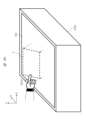
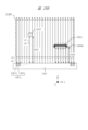
- 1 is a diagram showing an example of a usage form of a space floating image display device according to an embodiment of the present invention
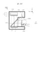
- 1 is a diagram showing an example of a main part configuration and a retroreflection part configuration of a space floating image display device according to an embodiment of the present invention
- 1 is a diagram showing an example of a main part configuration and a retroreflection part configuration of a space floating image display device according to an embodiment of the present invention
- 1 is a diagram showing an example of a main part configuration and a retroreflection part configuration of a space floating image display device according to an embodiment of the present invention
- 1 is a diagram showing an example of a main part configuration and a retroreflection part configuration of a floating-in-the-air image display device according to an embodiment of the present invention
- 1 is a projection diagram of a retroreflector constituting a floating-in-the-air image display device according to an embodiment of the present invention
- FIG. 2 is a top view of a retroreflector constituting a floating-in-the-air image display device according to an embodiment of the present invention.
- FIG. 2 is a perspective view showing a corner reflector constituting a retroreflector constituting a floating-in-the-air image display device according to an embodiment of the present invention.
- FIG. 2 is a top view showing a corner reflector constituting a retroreflector constituting a floating-in-the-air image display device according to an embodiment of the present invention.
- 1 is a side view showing a corner reflector constituting a retroreflector constituting a floating-in-the-air image display device according to an embodiment of the present invention;
- FIG. 1 is a diagram showing a configuration example of a space floating image display device according to an embodiment of the present invention
- FIG. 1 is a diagram showing an example of a configuration of a space floating image display device according to an embodiment of the present invention.
- FIG. 1 is a diagram showing an example of a configuration of a space floating image display device according to an embodiment of the present invention.
- FIG. 1 is a diagram showing an example of a configuration of a space floating image display device according to an embodiment of the present invention.
- FIG. 1 is a diagram showing an example of a configuration of a space floating image display device according to an embodiment of the present invention.
- FIG. 1 is a diagram showing an example of a configuration of a space floating image display device according to an embodiment of the present invention.
- FIG. 1 is a diagram showing an example of a configuration of a space floating image display device according to an embodiment of the present invention.
- FIG. 1 is a diagram showing an example of a configuration of a space floating image display device according to an embodiment of the present invention.
- FIG. 1 is a diagram showing an example of a configuration of a space floating image display device according to an embodiment of the present invention.
- FIG. 1 is a diagram showing an example of a configuration of a space floating image display device according to an embodiment of the present invention.
- FIG. 1 is a diagram showing an example of a configuration of a space floating image display device according to an embodiment of the present invention.
- FIG. 1 is a diagram showing an example of a configuration of a space floating image display device according to an embodiment of the present invention.
- FIG. 1 is a diagram showing an example of a configuration of a space floating image display device according to an embodiment of the present invention.
- FIG. 1 is a diagram showing an example of a configuration of a space floating image display device according to an embodiment of the present invention.
- FIG. 1 is a diagram showing an example of a configuration of a space floating image display device according to an embodiment of the present invention.
- FIG. 1 is a diagram showing an example of a configuration of a space floating image display device according to an embodiment of the present invention.
- FIG. 1 is a diagram showing an example of a configuration of a space floating image display device according to an embodiment of the present invention.
- FIG. 1 is a diagram showing an example of a configuration of a space floating image display device according to an embodiment of the present invention.
- FIG. 2 is a cross-sectional view showing an example of a specific configuration of a light source device according to an embodiment of the present invention.
- FIG. 2 is a cross-sectional view showing an example of a specific configuration of a light source device according to an embodiment of the present invention.
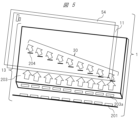
- 1 is a layout diagram showing a main part of a space floating image display device according to an embodiment of the present invention; 1 is a cross-sectional view showing a configuration of a display device according to an embodiment of the present invention. 1 is a cross-sectional view showing a configuration of a display device according to an embodiment of the present invention. 1 is an explanatory diagram for explaining a light source diffusion characteristic of an image display device according to an embodiment of the present invention.
- FIG. 1 is an explanatory diagram for explaining the diffusion characteristics of a video display device according to an embodiment of the present invention
- 1 is a diagram illustrating an example of a problem to be solved by image processing according to an embodiment of the present invention
- FIG. 4 is an explanatory diagram of an example of image processing according to an embodiment of the present invention.
- FIG. 4 is an explanatory diagram of an example of a video display process according to an embodiment of the present invention.
- FIG. 4 is an explanatory diagram of an example of a video display process according to an embodiment of the present invention.
- FIG. 1 is a diagram showing an example of a main part configuration and a retroreflection part configuration of a space floating image display device according to an embodiment of the present invention
- 1 is a diagram showing the configuration of a space floating image display system according to an embodiment of the present invention
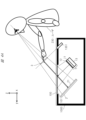
- 1 is a diagram showing an overview of a space floating image display system according to an embodiment of the present invention
- FIG. 2 is a diagram showing a configuration of a mobile terminal according to an embodiment of the present invention.
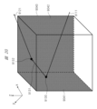
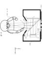
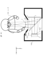
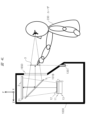
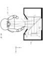
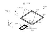
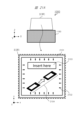
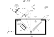
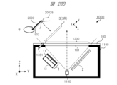
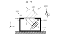
- 1 is a perspective view showing an insertion and touch operation of a mobile terminal into a floating image in space according to an embodiment of the present invention
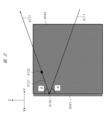
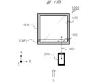
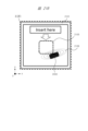
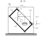
- 1 is an XY plan view showing an insertion and touch operation of a mobile terminal into a floating image in space according to an embodiment of the present invention
- 1 is a YZ plane view showing an insertion and touch operation of a mobile terminal into a floating image in space according to an embodiment of the present invention
- 1 is an XZ plane view showing an insertion and touch operation of a mobile terminal into a floating image in space according to an embodiment of the present invention
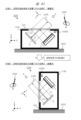
- 1 is a perspective view showing the posture of a mobile terminal when inserting and touching the floating-in-space image according to an embodiment of the present invention
- 1A and 1B are XY plan views showing examples of postures when inserting and touching a mobile terminal into a floating-in-space image according to an embodiment of the present invention.
- 1A and 1B are YZ plane views showing examples of postures when inserting and touching a mobile terminal into a floating-in-space image according to an embodiment of the present invention.
- 1A and 1B are XZ plan views showing examples of postures when inserting and touching a mobile terminal into a floating-in-space image according to an embodiment of the present invention.
- 1A and 1B are YZ plane views showing examples of postures when inserting and touching a mobile terminal into a floating-in-space image according to an embodiment of the present invention.
- 1A and 1B are YZ plane views showing examples of postures when inserting and touching a mobile terminal into a floating-in-space image according to an embodiment of the present invention.
- 1 is a YZ plane view showing an example of a position when inserting and touching a mobile terminal into a floating-in-space image according to an embodiment of the present invention
- 1 is an XY plan view showing an example of a position when inserting and touching a mobile terminal into a floating-in-space image according to an embodiment of the present invention
- 1 is a YZ plane view showing an example of a position when inserting and touching a mobile terminal into a floating-in-space image according to an embodiment of the present invention
- FIG. 13 is an explanatory diagram showing an example of a guide image being displayed on a floating-in-space image according to an embodiment of the present invention.
- FIG. 13 is an explanatory diagram showing an example of a guide image being displayed on a floating-in-space image according to an embodiment of the present invention.
- 1 is an XY plan view showing an example of a mobile terminal touching a floating image in space according to an embodiment of the present invention
- 11 is an XZ plane view showing an example of an invisible area caused by contact of a mobile terminal with a floating-in-space image according to an embodiment of the present invention
- FIG. 11 is a YZ plane view showing an example of shading caused by contact of a mobile terminal with a floating-in-space image according to an embodiment of the present invention
- FIG. 11 is an xy plan view showing an example of a guide image displayed on a floating-in-space image according to an embodiment of the present invention, and an example of an invisible area due to contact with a mobile terminal.
- FIG. 11 is an xy plan view showing an example of displaying a guide image on a space floating image according to an embodiment of the present invention and an example of limiting a display area.
- FIG. 13 is an xy plan view showing an example of a guide image displayed on a floating-in-space image according to an embodiment of the present invention.
- FIG. 13 is an xy plan view showing an example of a guide image displayed on a floating-in-space image according to an embodiment of the present invention.
- FIG. 1A and 1B are explanatory diagrams showing an example of displaying a guide image on a space floating image and an example of limiting a display area according to an embodiment of the present invention.
- FIG. 4 is an explanatory diagram showing an example of a guide voice output according to an embodiment of the present invention.
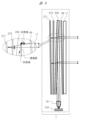
- FIG. 2 is a YZ plane cross-sectional view showing an example of the arrangement of sensors in a space floating image display device according to an embodiment of the present invention.
- FIG. 2 is an xy plan view showing an example of the configuration of an aerial operation detection sensor according to an embodiment of the present invention.
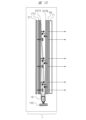
- FIG. 2 is a YZ plane cross-sectional view showing an example of the arrangement of sensors in a space floating image display device according to an embodiment of the present invention.
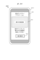
- FIG. 4 is an explanatory diagram showing a display example of an application screen on a mobile terminal according to an embodiment of the present invention.
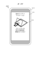
- FIG. 4 is an explanatory diagram showing a display example of an application screen on a mobile terminal according to an embodiment of the present invention.
- FIG. 4 is an explanatory diagram showing a display example of an application screen on a mobile terminal according to an embodiment of the present invention.
- FIG. 11 is an explanatory diagram showing a display example of a QR code screen on a mobile terminal according to an embodiment of the present invention.
- 1 is a YZ plane cross-sectional view showing an example of capturing an image of a QR code of a mobile terminal in a space floating image display device according to an embodiment of the present invention;
- FIG. 4 is an explanatory diagram showing a display example of an application screen on a mobile terminal according to an embodiment of the present invention.
- FIG. 4 is an explanatory diagram showing a display example of an application screen on a mobile terminal according to an embodiment of the present invention.
- FIG. 1 is a perspective view showing an example of a QR code displayed in a space floating image according to an embodiment of the present invention.
- 1 is a YZ plane cross-sectional view showing an example of capturing an image of a QR code of a space-floating image of a space-floating image display device by a mobile terminal according to an embodiment of the present invention
- FIG. 11 is a perspective view showing an example of a QR code displayed on a screen of a second display device according to an embodiment of the present invention.
- FIG. 1 is a diagram showing an example of the configuration of a system in which a mobile terminal and a space floating image display device are communicatively connected, according to an embodiment of the present invention.
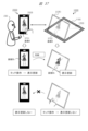
- FIG. 1A and 1B are diagrams showing an example of dual display between a mobile terminal and a space floating image display device according to an embodiment of the present invention.
- FIG. 2 is a diagram showing a basic control flow of a system according to an embodiment of the present invention.
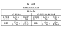
- FIG. 4 is a diagram showing an example of display and settings before connection of the system according to an embodiment of the present invention.
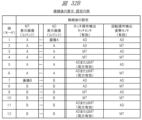
- FIG. 13 is a diagram showing an example (mode) of display and settings after the system is connected according to an embodiment of the present invention.
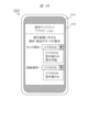
- FIG. 13 is a diagram showing a GUI example (1) for mode setting as an example of a screen display of a mobile terminal according to an embodiment of the present invention.
- FIG. 13 is a diagram showing a GUI example (2) for mode setting as an example of a screen display of a mobile terminal according to an embodiment of the present invention.
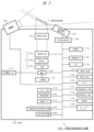
- FIG. 1 is a diagram showing an example of a functional block configuration of a system according to an embodiment of the present invention.
- 1A and 1B are diagrams showing an example of the configuration of a screen of a space floating image display device and an example of the configuration of a screen of a mobile terminal according to an embodiment of the present invention.
- FIG. 1 is a diagram showing an example 1 of a problem and a solution according to an embodiment of the present invention.
- FIG. 11 is a diagram showing an example 2 of a problem and a solution according to an embodiment of the present invention.
- FIG. 11 is a diagram showing Example 3 of a problem and a solution according to an embodiment of the present invention.
- FIG. 11 is a diagram showing Example 4 of a problem and a solution according to an embodiment of the present invention.
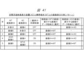
- 1A to 1C are diagrams showing examples (patterns) of image display on a space floating image display device and a mobile terminal according to an embodiment of the present invention.
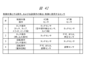
- 1A and 1B are diagrams showing examples of operations to be controlled and sensors used for control according to an embodiment of the present invention.
- 1A and 1B are diagrams showing Example 1 of the attitude of the space floating image display device according to an embodiment of the present invention;
- FIG. 11 is a diagram showing Example 2 of the attitude of the space floating image display device according to an embodiment of the present invention.
- FIG. 11A and 11B are diagrams showing Example 3 of the attitude of the space floating image display device according to an embodiment of the present invention.
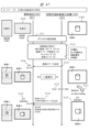
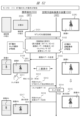
- FIG. 13 is a diagram showing an example (1) of a sequence of mode 1 according to one embodiment of the present invention.
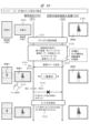
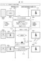
- FIG. 13 is a diagram showing an example (2) of a sequence of mode 1 according to one embodiment of the present invention.
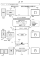
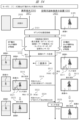
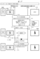
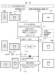
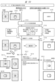
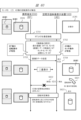
- FIG. 13 shows an example (3) of a sequence of mode 1 according to one embodiment of the present invention.
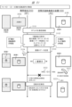
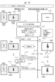
- FIG. 13 shows an example (4) of a sequence of mode 1 according to one embodiment of the present invention.
- FIG. 13 is a diagram showing an example (1) of a sequence of mode 2 according to one embodiment of the present invention.
- FIG. 13 is a diagram showing an example (2) of a sequence of mode 2 according to one embodiment of the present invention.
- FIG. 13 is a diagram showing an example (2) of a sequence of mode 2 according to one embodiment of the present invention.
- FIG. 13 is a diagram showing an example (1) of a sequence of mode 3 according to one embodiment of the present invention.
- FIG. 13 is a diagram showing an example (2) of a sequence of mode 3 according to one embodiment of the present invention.
- FIG. 13 shows an example (1) of a sequence of mode 5 according to one embodiment of the present invention.
- FIG. 13 shows an example (1) of a sequence of mode 7 according to one embodiment of the present invention.
- FIG. 13 is a diagram showing an example (2) of a sequence of mode 7 according to one embodiment of the present invention.
- FIG. 13 shows an example (3) of a sequence of mode 7 according to one embodiment of the present invention.
- FIG. 13 shows an example (4) of a sequence of mode 7 according to one embodiment of the present invention.
- FIG. 13 shows an example (1) of a sequence of mode 8 according to one embodiment of the present invention.
- FIG. 13 is a diagram showing an example (2) of a sequence of mode 8 according to one embodiment of the present invention.
- FIG. 13 is a diagram showing an example (1) of a sequence of mode 9 according to one embodiment of the present invention.
- FIG. 13 is a diagram showing an example (2) of a sequence of mode 9 according to one embodiment of the present invention.
- FIG. 13 shows an example (1) of a sequence of mode 11 according to one embodiment of the present invention.
- the following examples relate to an image display device that can transmit an image produced by image light from an image emission source through a transparent member that divides a space, such as glass, and display the image as a floating image outside the transparent member.
- an image that floats in space is expressed using the term "floating image in space.” Instead of this term, it is also acceptable to express it as "aerial image,” “spatial image,” “floating image in space,” “floating optical image of displayed image,” “floating optical image of displayed image,” etc.
- the term “floating image in space” that is mainly used in the explanation of the examples is used as a representative example of these terms.
- a suitable image display device can be realized in a bank ATM, a ticket vending machine at a station, a digital signage, etc.
- a touch panel is usually used in a bank ATM, a ticket vending machine at a station, etc., but a transparent glass surface or a light-transmitting plate material can be used to display high-resolution image information in a floating state on the glass surface or the light-transmitting plate material.
- a device including the light source of this embodiment can provide a new and highly usable floating image display device (floating image display system) that can significantly reduce power consumption.
- a floating image display device for a vehicle that can display a floating image in a one-way manner, which is visible inside and/or outside the vehicle, can be provided.
- FIG. 1 is a diagram showing an example of the use of a space-floating image display device according to an embodiment of the present invention, and is a diagram showing the overall configuration of the space-floating image display device according to this embodiment. The specific configuration of the space-floating image display device will be described in detail using FIG.
- the retroreflector 2 (retroreflector) is used as an example of the retroreflector.
- the retroreflector 2 of the present invention is not limited to a flat plate, and is used as an example of a concept including a sheet-like retroreflector attached to a flat or non-flat member, and an entire assembly in which a sheet-like retroreflector is attached to a flat or non-flat member. Furthermore, since the light rays reflected by the retroreflector 2 have the optical property of forming an image, the retroreflector 2 may be expressed as an imaging optical member or an imaging optical plate.
- the space is divided by a show window (also called “window glass”) 105, which is a translucent material such as glass.
- a show window also called “window glass”
- the inside of the window glass 105 (inside the store) is shown in the depth direction, with the outside (e.g., the sidewalk) in the foreground.
- the window glass 105 by providing the window glass 105 with a means for reflecting a specific polarized wave, it is possible to reflect the wave and form an aerial image at a desired position inside the store.
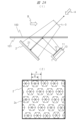
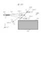
- FIG. 2A is a diagram showing an example of the configuration of an optical system of a space floating image display device according to an embodiment of the present invention.
- the configuration of the space floating image display device will be described in more detail using FIG. 2A.
- a display device 1 that diverges specific polarized image light at a narrow angle is provided in the oblique direction of a transparent member 100 such as glass.
- the display device 1 includes a liquid crystal display panel 11 and a light source device 13 that generates specific polarized light having a narrow angle diffusion characteristic.
- the image light of a specific polarization from the display device 1 is reflected by the polarization separation member 101 (in the figure, the polarization separation member 101 is formed into a sheet and adhered to the transparent member 100) having a film that selectively reflects the image light of a specific polarization provided on the transparent member 100, and enters the retroreflector 2.
- a ⁇ /4 plate 21 is provided on the image light incidence surface of the retroreflector 2. The image light is made to pass through the ⁇ /4 plate 21 twice, when it enters the retroreflector 2 and when it leaves, and is polarized and converted from the specific polarization to the other polarization.
- the polarization separation member 101 that selectively reflects the image light of a specific polarization has the property of transmitting the polarized light of the other polarization that has been polarized and converted, so the image light of the specific polarization after polarization conversion passes through the polarization separation member 101.
- the image light that has passed through the polarization separation member 101 forms a real image, a floating image 3, outside the transparent member 100.
- FIG. 2A shows an example in which the chief ray of the image light incident on the retroreflector 2 is incident at 90° to the retroreflector 2.
- the incident angle of the chief ray of the image light on the retroreflector 2 is not limited to 90°, and can also be, for example, 90° ⁇ 15°.
- the display device 1 may be configured to emit S-polarized image light to the polarization separation member 101, which may have the property of reflecting S-polarized light and transmitting P-polarized light.
- the S-polarized image light reaching the polarization separation member 101 from the display device 1 is reflected by the polarization separation member 101 and travels toward the retroreflector 2.
- the image light is reflected by the retroreflector 2, it passes through the ⁇ /4 plate 21 provided on the incident surface of the retroreflector 2 twice, so that the image light is converted from S-polarized light to P-polarized light.
- the image light converted to P-polarized light travels again toward the polarization separation member 101.
- the polarization separation member 101 has the property of reflecting S-polarized light and transmitting P-polarized light, so that the P-polarized image light passes through the polarization separation member 101 and then through the transparent member 100.
- the image light that passes through the transparent member 100 is generated by the retroreflector 2, so it forms a floating image 3, which is an optical image of the image displayed on the display device 1, at a position that is in a mirror relationship with the image displayed on the display device 1 relative to the polarization separation member 101.
- This polarization design makes it possible to form the floating image 3 in an optimal manner.
- the display device 1 may be configured to emit P-polarized image light to the polarization separation member 101, and the polarization separation member 101 may have the property of reflecting P-polarized light and transmitting S-polarized light.
- the P-polarized image light that reaches the polarization separation member 101 from the display device 1 is reflected by the polarization separation member 101 and travels toward the retroreflector 2.
- the image light is reflected by the retroreflector 2, it passes through the ⁇ /4 plate 21 provided on the incident surface of the retroreflector 2 twice, so that the image light is converted from P-polarized light to S-polarized light.
- the image light converted to S-polarized light travels again toward the polarization separation member 101.
- the polarization separation member 101 has the property of reflecting P-polarized light and transmitting S-polarized light, so the S-polarized image light passes through the polarization separation member 101 and then through the transparent member 100.
- the image light that passes through the transparent member 100 is generated by the retroreflector 2, so it forms a floating image 3, which is an optical image of the image displayed on the display device 1, at a position that is in a mirror relationship with the image displayed on the display device 1 relative to the polarization separation member 101.
- This polarization design allows the floating image 3 to be formed optimally.
- the light that forms the floating image 3 is a collection of light rays that converge from the retroreflector 2 to the optical image of the floating image 3, and these light rays continue to travel in a straight line even after passing through the optical image of the floating image 3. Therefore, the floating image 3 is an image with high directionality, unlike the diffuse image light formed on a screen by a general projector or the like. Therefore, in the configuration of FIG. 2A, when a user views the floating image 3 from the direction of arrow A, the floating image 3 is seen as a bright image. However, when another person views the floating image 3 from the direction of arrow B, the floating image 3 cannot be seen as an image at all. This characteristic is very suitable for use in a system that displays images that require high security or highly confidential images that should be kept secret from people directly facing the user.
- the polarization axis of the reflected image light may become uneven.
- the reflection angle may also become uneven.
- Such uneven light may not maintain the polarization state and propagation angle assumed in the design.
- light with a polarization state and propagation angle that is not assumed in the design may re-enter the image display surface side of the liquid crystal display panel 11 directly from the position of the retroreflector 2 without passing through the polarization separation member.
- Such light with a polarization state and propagation angle that is not assumed in the design may be reflected by a component in the space floating image display device and then re-enter the image display surface side of the liquid crystal display panel 11.
- Such light that re-enters the image display surface side of the liquid crystal display panel 11 may be re-reflected by the image display surface of the liquid crystal display panel 11 that constitutes the display device 1, generating a ghost image and possibly degrading the image quality of the space floating image. Therefore, in this embodiment, an absorbing polarizing plate 12 may be provided on the image display surface of the display device 1.
- the image light emitted from the display device 1 is transmitted through the absorptive polarizer 12, and the reflected light returning from the polarization separation member 101 is absorbed by the absorptive polarizer 12, thereby suppressing the re-reflection. This makes it possible to prevent degradation of image quality due to ghost images of spatially floating images.
- the absorptive polarizer 12 may be a polarizer that absorbs P-polarized light. Also, if the display device 1 is configured to emit P-polarized image light to the polarization separation member 101, the absorptive polarizer 12 may be a polarizer that absorbs S-polarized light.
- the above-mentioned polarization separation member 101 may be formed, for example, from a reflective polarizing plate or a metal multilayer film that reflects a specific polarized wave.
- FIG. 2A (2) shows an example of the surface shape of a typical retroreflector 2.
- Light rays incident on the interior of regularly-arranged hexagonal prisms are reflected by the walls and bottoms of the hexagonal prisms and emitted as retroreflected light in a direction corresponding to the incident light, and a real image floating in space is displayed based on the image displayed on the display device 1.
- the resolution of this floating image in space depends not only on the resolution of the liquid crystal display panel 11, but also on the outer shape D and pitch P of the retroreflective portion of the retroreflector 2 shown in Figure 2A (2).
- the resolution of the floating image in space depends not only on the resolution of the liquid crystal display panel 11, but also on the outer shape D and pitch P of the retroreflective portion of the retroreflector 2 shown in Figure 2A (2).
- the resolution of the floating image in space depends not only on the resolution of the liquid crystal display panel 11, but also on the outer shape D and pitch P of the retroreflective portion of the retroreflector 2 shown in Figure 2A (2).
- the resolution of the floating image in space will be reduced to about 1/3.
- the diameter and pitch of the retroreflective portion close to that of one pixel of the liquid crystal display panel.
- the pitch ratio of each it is advisable to design the pitch ratio of each to be a different integer multiple of one pixel.
- the surface shape of the retroreflector of this embodiment is not limited to the above example. It may have various surface shapes that realize retroreflection. Specifically, the surface of the retroreflector of this embodiment may be provided with retroreflection elements in which triangular pyramid prisms, hexagonal pyramid prisms, other polygonal prisms, or combinations of these are periodically arranged. Alternatively, the surface of the retroreflector of this embodiment may be provided with retroreflection elements in which these prisms are periodically arranged to form cube corners. These can also be expressed as corner reflector arrays and multifaceted reflector arrays. Alternatively, the surface of the retroreflector of this embodiment may be provided with capsule lens-type retroreflection elements in which glass beads are periodically arranged.
- FIG. 2B Another example of the configuration of the optical system of the space floating image display device will be described with reference to Fig. 2B.
- Fig. 2B the components with the same reference numerals as Fig. 2A have the same functions and configurations as Fig. 2A. For such components, repeated explanations will be omitted to simplify the explanation.
- image light of a specific polarization is output from the display device 1.
- the image light of a specific polarization output from the display device 1 is input to the polarization separation member 101B.
- the polarization separation member 101B is a member that selectively transmits the image light of a specific polarization.
- the polarization separation member 101B is not integrated with the transparent member 100, but has an independent plate-like shape. Therefore, the polarization separation member 101B may be expressed as a polarization separation plate.
- the polarization separation member 101B may be configured as a reflective polarizing plate configured by attaching a polarization separation sheet to a transparent member, for example.
- the transparent member may be formed of a metal multilayer film that selectively transmits a specific polarization and reflects the polarization of other specific polarizations.
- the polarization separation member 101B is configured to transmit the image light of a specific polarization output from the display device 1.
- the image light that has passed through the polarization separation member 101B enters the retroreflector 2.
- a ⁇ /4 plate 21 is provided on the image light incident surface of the retroreflector.
- the image light is polarized and converted from a specific polarization to the other polarization by passing through the ⁇ /4 plate 21 twice, when it enters the retroreflector and when it leaves.
- the polarization separation member 101B has the property of reflecting the polarized light of the other polarization that has been polarized and converted by the ⁇ /4 plate 21, so the image light after polarization conversion is reflected by the polarization separation member 101B.
- the image light reflected by the polarization separation member 101B passes through the transparent member 100 and forms a spatially floating image 3, which is a real image, outside the transparent member 100.
- the display device 1 may be configured to emit P-polarized image light to the polarization separation member 101B, which has the property of reflecting S-polarized light and transmitting P-polarized light.
- the P-polarized image light that reaches the polarization separation member 101B from the display device 1 passes through the polarization separation member 101B and heads toward the retroreflector 2.
- the image light is reflected by the retroreflector 2, it passes through the ⁇ /4 plate 21 provided on the incident surface of the retroreflector 2 twice, so that the image light is converted from P-polarized light to S-polarized light.
- the image light converted to S-polarized light heads again toward the polarization separation member 101B.
- the polarization separation member 101B has the property of reflecting S-polarized light and transmitting P-polarized light, so the S-polarized image light is reflected by the polarization separation member 101 and transmits through the transparent member 100.
- the image light that passes through the transparent member 100 is generated by the retroreflector 2, and therefore forms a floating image 3, which is an optical image of the image displayed on the display device 1, at a position that is in a mirror relationship with the image displayed on the display device 1 relative to the polarization separation member 101B.
- This polarization design allows the floating image 3 to be formed optimally.
- the display device 1 may be configured to emit S-polarized image light to the polarization separation member 101B, which has the property of reflecting P-polarized light and transmitting S-polarized light.
- the S-polarized image light that reaches the polarization separation member 101B from the display device 1 passes through the polarization separation member 101B and heads toward the retroreflector 2.
- the image light is reflected by the retroreflector 2, it passes through the ⁇ /4 plate 21 provided on the incident surface of the retroreflector 2 twice, so that the image light is converted from S-polarized light to P-polarized light.
- the image light converted to P-polarized light heads again toward the polarization separation member 101B.
- the polarization separation member 101B has the property of reflecting P-polarized light and transmitting S-polarized light, so that the P-polarized image light is reflected by the polarization separation member 101 and passes through the transparent member 100.
- the image light that passes through the transparent member 100 is generated by the retroreflector 2, so it forms a floating image 3, which is an optical image of the image displayed on the display device 1, at a position that is in a mirror relationship with the image displayed on the display device 1 relative to the polarization separation member 101B.
- This polarization design allows the floating image 3 to be formed optimally.
- the image display surface of the display device 1 and the surface of the retroreflector 2 are arranged parallel to each other.
- the polarized light separating member 101B is arranged at an angle ⁇ (e.g., 30°) with respect to the image display surface of the display device 1 and the surface of the retroreflector 2.
- ⁇ e.g. 30°
- the traveling direction of the image light reflected by the polarized light separating member 101B differs by an angle ⁇ (e.g., 60°) from the traveling direction of the image light incident from the retroreflector 2 (the direction of the chief ray of the image light).
- the image light is output at a predetermined angle shown in the figure toward the outside of the transparent member 100, forming the space-floating image 3, which is a real image.
- the space-floating image 3 is viewed as a bright image.
- the space-floating image 3 cannot be viewed as an image at all. This characteristic is highly suitable for use in systems that display images that require high security or highly confidential images that should be concealed from people directly facing the user.
- the optical system of FIG. 2B is an optical system with a different configuration from the optical system of FIG. 2A, but can form a suitable floating image in space, just like the optical system of FIG. 2A.
- An absorptive polarizing plate may be provided on the surface of the transparent member 100 facing the polarization separation member 101B.
- the absorptive polarizing plate may transmit the polarized waves of the image light from the polarization separation member 101B and absorb the polarized waves that are 90° out of phase with the polarized waves of the image light from the polarization separation member 101B.
- the image light for forming the space-floating image 3 is sufficiently transmitted while the external light incident from the space-floating image 3 side of the transparent member 100 can be reduced by about 50%. This makes it possible to reduce stray light in the optical system of FIG. 2B due to the external light incident from the space-floating image 3 side of the transparent member 100.
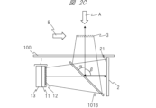
- FIG. 2C Another example of the configuration of the optical system of the space floating image display device will be described with reference to Fig. 2C.
- Fig. 2C the components with the same reference numerals as those in Fig. 2B have the same functions and configurations as those in Fig. 2B. For the sake of simplicity, the description of such components will not be repeated.
- the only difference between the optical system in FIG. 2B and the optical system in FIG. 2C is the angle at which the polarization separation member 101B is disposed relative to the image display surface of the display device 1 and the surface of the retroreflector 2. All other configurations are similar to the optical system in FIG. 2B, so a repeated description will be omitted.
- the polarization design of the optical system in FIG. 2C is also similar to the polarization design of the optical system in FIG. 2B, so a repeated description will be omitted.
- the polarization separation member 101B is arranged at an angle ⁇ with respect to the image display surface of the display device 1 and the surface of the retroreflector 2.
- the angle ⁇ is 45°.
- the angle ⁇ between the traveling direction of the image light reflected by the polarization separation member 101B (direction of the chief ray of the image light) and the traveling direction of the image light incident from the retroreflector 2 is 90°.
- the image display surface of the display device 1 and the surface of the retroreflector 2 are perpendicular to the traveling direction of the image light reflected by the polarization separation member 101B, and the angular relationship of the surfaces constituting the optical system can be simplified. If the surface of the transparent member 100 is arranged so as to be perpendicular to the traveling direction of the image light reflected by the polarization separation member 101B, the angular relationship of the surfaces constituting the optical system can be further simplified.
- FIG. 2C when a user views the image from the direction of arrow A, the floating image 3 is perceived as a bright image. However, when another person views the image from the direction of arrow B, the floating image 3 cannot be seen as an image at all. This characteristic is very suitable for use in a system that displays images that require high security or highly confidential images that should be concealed from people directly facing the user.
- the optical system of FIG. 2C is an optical system with a different configuration from the optical systems of FIG. 2A and FIG. 2B, but can form a suitable floating image in space, similar to the optical system of FIG. 2A and FIG. 2B.
- the angles of the surfaces that make up the optical system can be made simpler.
- An absorptive polarizing plate may be provided on the surface of the transparent member 100 facing the polarization separation member 101B.
- the absorptive polarizing plate may transmit the polarized waves of the image light from the polarization separation member 101B and absorb the polarized waves that are 90° out of phase with the polarized waves of the image light from the polarization separation member 101B.
- the image light for forming the space-floating image 3 is sufficiently transmitted while the external light incident from the space-floating image 3 side of the transparent member 100 can be reduced by about 50%. This makes it possible to reduce stray light in the optical system of FIG. 2C due to the external light incident from the space-floating image 3 side of the transparent member 100.
- FIG. 2D Another example of the configuration of the optical system of the space floating image display device will be described with reference to FIG. 2D.
- the optical system of FIG. 2D is an optical system using a retroreflector 5 different from the retroreflector 2 used in FIG. 2A to FIG. 2C.
- Another example of the configuration 3 of the optical system will be described in more detail below with reference to FIG. 2D to FIG. 2I.
- the components with the same reference numerals as those in FIG. 2A to FIG. 2C have the same functions and configurations as those in FIG. 2A to FIG. 2C. Such components will not be described repeatedly in order to simplify the explanation.
- FIG. 2D is a diagram showing an example of the main components and retroreflective components of a spatial floating image display device according to one embodiment of the present invention.
- a display device 10 that emits image light is provided in an oblique direction of a transparent member 100 such as glass.
- the display device 10 includes a liquid crystal display panel 11 and a light source device 13 that generates light.
- the chief ray 9020 which represents the light beam emitted from the display device 10, travels toward the retroreflector 5 and is incident on the retroreflector 5 at an incident angle ⁇ .
- the incident angle ⁇ may be, for example, 45°.
- the incident angle ⁇ is not limited to 45°, and may be, for example, 45° ⁇ 15°.
- the retroreflector 5 is an optical element that has the optical property of retroreflecting light rays in at least some directions.
- the retroreflector 5 may also be referred to as an imaging optical element or imaging optical plate.
- the retroreflector 5 causes the main ray 9020 to travel in the z direction while being retroreflected in the x and y directions.
- the reflected ray 9021 travels along an optical path that is mirror-symmetrical to the main ray 9020 with the retroreflector 5 as the reference, in a direction away from the retroreflector 5, passes through the transparent member 100, and forms the floating-in-space image 3 as a real image on the imaging plane.
- the light beam that forms the floating image 3 is a collection of light rays that converge from the retroreflector 5 to the optical image of the floating image 3, and these light rays continue to travel in a straight line even after passing through the optical image of the floating image 3. Therefore, the floating image 3 is an image with high directionality, unlike a diffuse image formed on a screen by a general projector or the like. Therefore, in the configuration of Figure 2, when a user views the floating image 3 from the direction of arrow A, the floating image 3 is seen as a bright image. However, when another person views the floating image 3 from the direction of arrow B, the floating image 3 cannot be seen as an image at all. This characteristic is suitable for use in a system that displays images that require high security or highly confidential images that should be kept secret from people directly facing the user.
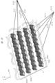
- the retroreflector 5 is configured by arranging multiple corner reflectors 9040 in an array on the surface of a transparent member 50. This may be called a corner reflector array or a multi-surface reflector array.
- the specific configuration of the corner reflector 9040 will be described in detail using Figures 2G, 2H, and 2I.
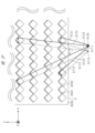
- Light rays 9111, 9112, 9113, and 9114 emitted from a light source 9110 are reflected twice by two mirror surfaces 9041 and 9042 of the corner reflector 9040, becoming reflected light rays 9121, 9122, 9123, and 9124.
- This double reflection is a retroreflection that turns back in the same direction as the incident direction (travels in a direction rotated 180 degrees) in the x and y directions, and a regular reflection in which the incident angle and reflection angle match due to total reflection in the z direction.
- the light rays 9111 to 9114 generate reflected light rays 9121 to 9124 on a straight line symmetrical in the z direction with respect to the corner reflector 9040, forming an aerial real image 9120.
- the light rays 9111 to 9114 emitted from the light source 9110 are four light rays that represent the diffused light from the light source 9110, and although the light rays that enter the retroreflector 5 are not limited to these depending on the diffusion characteristics of the light source 9110, all of the incident light rays cause similar reflections and form an aerial real image 9120.
- the position of the light source 9110 and the position of the aerial real image 9120 in the x direction are shifted, but in reality the position of the light source 9110 and the position of the aerial real image 9120 in the x direction are the same, and are overlapping when viewed from the z direction.
- the corner reflector 9040 is a rectangular parallelepiped with only two specific faces being mirror surfaces 9041 and 9042, and the other four faces being made of transparent material.
- the retroreflector 5 has a configuration in which the corner reflectors 9040 are arrayed so that the corresponding mirror surfaces face in the same direction.
- mirror surface 9041 When viewed from the top (+z direction), light ray 9111 emitted from light source 9110 is incident on mirror surface 9041 (or mirror surface 9042) at a specific angle of incidence, is totally reflected at reflection point 9130, and is then totally reflected again at reflection point 9132 on mirror surface 9042 (or mirror surface 9041).
- the angle of incidence of light ray 9111 with respect to mirror surface 9041 (or mirror surface 9042) is ⁇
- the angle of incidence of the first reflected light ray 9131 reflected by mirror surface 9041 (or mirror surface 9042) with respect to mirror surface 9042 (or mirror surface 9041) can be expressed as 90°- ⁇ . Therefore, with respect to light ray 9111, the second reflected light ray 9121 rotates by 2 ⁇ after the first reflection and by 2 ⁇ (90°- ⁇ ) after the second reflection, resulting in a total inversion optical path of 180°.
- total reflection in the z direction occurs only once. Therefore, if the angle of incidence with respect to mirror surface 9041 or mirror surface 9042 is ⁇ , the reflected light ray 9121 rotates by 2 ⁇ after one reflection with respect to light ray 9111.
- the light rays incident on the corner reflector 9040 undergo retroreflection with inverted optical paths in the x and y directions, and undergo regular reflection due to total reflection in the z direction.
- the retroreflector 5 Similar reflections occur in each optical path, so that an image is formed at a point symmetrical with respect to the z-axis direction due to the inverted optical paths that are convergent in the x and y directions.
- the retroreflector 2 has retroreflection properties in three axial directions.
- the convergent reflected light beam travels towards the side of the retroreflector 2 where the light source of the incident light is located.
- This convergent reflected light beam forms an image in the air to form a floating image 3.
- the traveling direction of the chief ray of the convergent reflected light beam reflected from the retroreflector 2 is the opposite direction to the traveling direction of the chief ray of the diffusive incident light beam that is incident on the retroreflector 2.
- the retroreflector 5 has retroreflection properties in two axial directions, and is specular in the other axial direction.
- the retroreflector 5 when a diffusive incident light beam is incident on the retroreflector 5, the convergent reflected light beam reflected by the corner reflector array travels toward the side of the retroreflector 5 opposite the side where the light source of the incident light is located. This convergent reflected light beam forms an image in the air, forming the floating image 3.
- the direction of travel of the chief ray of the convergent reflected light beam reflected by the corner reflector array of the retroreflector 5 is not the opposite direction to the direction of travel of the chief ray of the diffusive incident light beam incident on the retroreflector 5.
- the normal component of the plate-shaped surface of the retroreflector 5 in the direction of travel of the chief ray of the diffusive incident light beam incident on the retroreflector 5 and the normal component of the plate-shaped surface of the retroreflector 5 in the direction of travel of the chief ray after being reflected by the retroreflector 5 to become a convergent reflected light beam continue to travel in a straight line before and after reflection by the corner reflector array.
- the diffusive incident light beam is converted into a convergent reflected light beam by reflection on the retroreflector 5, but in the normal direction to the plate-shaped surface of the retroreflector 5, this light beam travels as if passing through the retroreflector 5.
- the diffusive incident light beam that enters the retroreflector 5 and the convergent reflected light beam that exits from the retroreflector 5 are geometrically symmetrical with respect to the plate-shaped surface of the retroreflector 5.
- the resolution of the floating image formed by the light from the video output unit 10 depends heavily on the diameter D and pitch P (not shown) of the retroreflective portion of the retroreflector 5 shown in Figures 2E and 2F, in addition to the resolution of the liquid crystal display panel 11.
- D and pitch P not shown
- the diameter D of the retroreflective portion is 240 ⁇ m and the pitch P is 300 ⁇ m
- one pixel of the floating image in space will be equivalent to 300 ⁇ m.
- the effective resolution of the floating image in space will be reduced to about 1/3.
- the diameter D and pitch P of the retroreflective portion close to one pixel of the liquid crystal display panel.
- the pitch ratio of each it is advisable to design the pitch ratio of each to be a different integer multiple of one pixel.
- the shape of the retroreflector (imaging optical plate) according to this embodiment is not limited to the above example. It may have various shapes that realize retroreflection. Specifically, it may be various cubic corner bodies, corner reflector arrays, slit mirror arrays, two-sided corner reflector arrays, polyhedral reflector arrays, or shapes in which a combination of their reflective surfaces is periodically arranged. Alternatively, a capsule lens type retroreflection element in which glass beads are periodically arranged may be provided on the surface of the retroreflection plate of this embodiment. The detailed configuration of these retroreflection elements can be achieved by using existing technology, so a detailed description will be omitted. Specifically, it is possible to use the technology disclosed in JP2017-33005A, JP2019-133110A, JP2017-67933A, WO2009/131128A, etc.
- the image light emitted from the display device 10 can be in any polarization state. It does not matter whether it is S-polarized or P-polarized.
- the optical system of FIG. 2D is an optical system that uses a different retroreflector than the optical systems of FIG. 2A to FIG. 2C, but it can form a more suitable floating image in space, just like the optical systems of FIG. 2A to FIG. 2C.
- optical systems of Figures 2A, 2B, 2C, and 2D described above can provide brighter, higher quality floating images.
- Figure 3 is a block diagram showing an example of the internal configuration of the space floating image display device 1000.
- the floating-in-space image display device 1000 includes a retroreflection unit 1101, an image display unit 1102, a light guide 1104, a light source 1105, a power source 1106, an external power source input interface 1111, an operation input unit 1107, a non-volatile memory 1108, a memory 1109, a control unit 1110, an image signal input unit 1131, an audio signal input unit 1133, a communication unit 1132, an aerial operation detection sensor 1351, an aerial operation detection unit 1350, an audio output unit 1140, a microphone 1139, an image control unit 1160, a storage unit 1170, an imaging unit 1180, and the like. It may also include a removable media interface 1134, an attitude sensor 1113, a transmissive self-luminous image display device 1650, a second display device 1680, or a secondary battery 1112.
- the components of the space floating image display device 1000 are arranged in a housing 1190.
- the imaging unit 1180 and the aerial operation detection sensor 1351 shown in FIG. 3 may be provided on the outside of the housing 1190.
- the retroreflective portion 1101 in FIG. 3 corresponds to the retroreflective plate 2 in FIG. 2A, FIG. 2B, and FIG. 2C.
- the retroreflective portion 1101 retroreflects light modulated by the image display portion 1102.
- the light reflected from the retroreflective portion 1101 is output to the outside of the space-floating image display device 1000 to form the space-floating image 3.
- the image display unit 1102 in FIG. 3 corresponds to the liquid crystal display panel 11 in FIG. 2A, FIG. 2B, and FIG. 2C.
- the light source 1105 in FIG. 3 corresponds to the light source device 13 in FIG. 2A, FIG. 2B, and FIG. 2C.
- the image display unit 1102, the light guide 1104, and the light source 1105 in FIG. 3 correspond to the display device 1 in FIG. 2A, FIG. 2B, and FIG. 2C.
- the video display unit 1102 is a display unit that generates an image by modulating transmitted light based on a video signal input under the control of the video control unit 1160 described below.
- the video display unit 1102 corresponds to the liquid crystal display panel 11 of Figures 2A, 2B, and 2C.
- a transmissive liquid crystal panel is used as the video display unit 1102.
- a reflective liquid crystal panel that modulates reflected light or a DMD (Digital Micromirror Device: registered trademark) panel may be used as the video display unit 1102.
- the light source 1105 generates light for the image display unit 1102 and is a solid-state light source such as an LED light source or a laser light source.
- the power source 1106 converts AC current input from the outside via the external power input interface 1111 into DC current and supplies power to the light source 1105.
- the power source 1106 also supplies the necessary DC current to each part in the space-floating image display device 1000.
- the secondary battery 1112 stores the power supplied from the power source 1106.
- the secondary battery 1112 also supplies power to the light source 1105 and other components that require power when power is not supplied from the outside via the external power input interface 1111. In other words, when the space-floating image display device 1000 is equipped with the secondary battery 1112, the user can use the space-floating image display device 1000 even when power is not supplied from the outside.
- the light guide 1104 guides the light generated by the light source 1105 and irradiates it onto the image display unit 1102.
- the combination of the light guide 1104 and the light source 1105 can also be called the backlight of the image display unit 1102.
- the light guide 1104 may be configured mainly using glass.
- the light guide 1104 may be configured mainly using plastic.
- the light guide 1104 may be configured using a mirror. There are various methods for combining the light guide 1104 and the light source 1105. Specific configuration examples for the combination of the light guide 1104 and the light source 1105 will be explained in detail later.
- the aerial operation detection sensor 1351 is a sensor that detects the operation of the floating-in-space image 3 by the finger of the user 230.
- the aerial operation detection sensor 1351 senses, for example, a range that overlaps with the entire display range of the floating-in-space image 3. Note that the aerial operation detection sensor 1351 may only sense a range that overlaps with at least a portion of the display range of the floating-in-space image 3.
- the aerial operation detection sensor 1351 include a distance sensor that uses invisible light such as infrared rays, an invisible light laser, ultrasonic waves, etc.
- the aerial operation detection sensor 1351 may also be configured to detect coordinates on a two-dimensional plane by combining multiple sensors.
- the aerial operation detection sensor 1351 may also be configured with a ToF (Time of Flight) type LiDAR (Light Detection and Ranging) or an image sensor.
- ToF Time of Flight
- LiDAR Light Detection and Ranging
- the mid-air operation detection sensor 1351 only needs to be capable of sensing to detect touch operations, etc., performed by the user with his/her finger on an object displayed as the floating-in-space image 3. Such sensing can be performed using existing technology.
- the aerial operation detection unit 1350 acquires a sensing signal from the aerial operation detection sensor 1351, and performs operations such as determining whether or not the finger of the user 230 has touched an object in the floating-in-space image 3 and calculating the position (contact position) at which the finger of the user 230 has touched the object based on the sensing signal.
- the aerial operation detection unit 1350 is configured with a circuit such as an FPGA (Field Programmable Gate Array). Some of the functions of the aerial operation detection unit 1350 may also be realized by software, for example, by a spatial operation detection program executed by the control unit 1110.
- the aerial operation detection sensor 1351 and the aerial operation detection unit 1350 may be configured to be built into the space-floating image display device 1000, or may be provided separately from the space-floating image display device 1000. When provided separately from the space-floating image display device 1000, the aerial operation detection sensor 1351 and the aerial operation detection unit 1350 are configured to transmit information and signals to the space-floating image display device 1000 via a wired or wireless communication connection path or image signal transmission path.
- the aerial operation detection sensor 1351 and the aerial operation detection unit 1350 may be provided separately. This makes it possible to build a system in which the air-floating image display device 1000, which does not have an aerial operation detection function, is the main body, and only the aerial operation detection function can be added as an option. Also, a configuration in which only the aerial operation detection sensor 1351 is a separate unit, and the aerial operation detection unit 1350 is built into the air-floating image display device 1000, may be used. In cases where it is desired to more freely position the aerial operation detection sensor 1351 relative to the installation position of the air-floating image display device 1000, a configuration in which only the aerial operation detection sensor 1351 is a separate unit is advantageous.
- the imaging unit 1180 is a camera with an image sensor, and captures the space near the floating-in-space image 3 and/or the face, arms, fingers, etc. of the user 230.
- a plurality of imaging units 1180 may be provided. By using a plurality of imaging units 1180, or by using an imaging unit with a depth sensor, it is possible to assist the aerial operation detection unit 1350 in detecting the touch operation of the floating-in-space image 3 by the user 230.
- the imaging unit 1180 may be provided separately from the floating-in-space image display device 1000. When the imaging unit 1180 is provided separately from the floating-in-space image display device 1000, it is sufficient to configure it so that an imaging signal can be transmitted to the floating-in-space image display device 1000 via a wired or wireless communication connection path, etc.
- the aerial operation detection sensor 1351 may not be able to detect information such as how far an object that has not intruded into the intrusion detection plane (e.g., a user's finger) is from the intrusion detection plane, or how close the object is to the intrusion detection plane.
- the distance between the object and the intrusion detection plane can be calculated by using information such as object depth calculation information based on the captured images of the multiple image capturing units 1180 and object depth information from the depth sensor.
- This information, as well as various other information such as the distance between the object and the intrusion detection plane, are used for various display controls for the floating in space image 3.
- the aerial operation detection unit 1350 may detect a touch operation of the floating-in-space image 3 by the user 230 based on the captured image of the imaging unit 1180.
- the imaging unit 1180 may also capture an image of the face of the user 230 operating the floating image 3, and the control unit 1110 may perform an identification process for the user 230.
- the imaging unit 1180 may also capture an image of the user 230 operating the floating image 3 and a range including the user 230 operating the floating image 3 and the surrounding area of the user 230, in order to determine whether or not another person is standing around or behind the user 230 operating the floating image 3 and peeking at the user's operation of the floating image 3.
- the operation input unit 1107 is, for example, an operation button, a signal receiving unit such as a remote controller, or an infrared light receiving unit, and inputs a signal for an operation different from the aerial operation (touch operation) by the user 230.
- the operation input unit 1107 may be used, for example, by an administrator to operate the floating-in-space image display device 1000.
- Video signal input unit 1131 connects to an external video output device and inputs video data.
- Various digital video input interfaces are possible for video signal input unit 1131.
- it may be configured with a video input interface conforming to the HDMI (registered trademark) (High-Definition Multimedia Interface) standard, a video input interface conforming to the DVI (Digital Visual Interface) standard, or a video input interface conforming to the DisplayPort standard.
- HDMI registered trademark
- DVI Digital Visual Interface
- DisplayPort DisplayPort
- an analog video input interface such as analog RGB or composite video may be provided.
- the audio signal input unit 1133 connects an external audio output device and inputs audio data.
- the audio signal input unit 1133 may be configured as an HDMI standard audio input interface, an optical digital terminal interface, a coaxial digital terminal interface, or the like.
- the video signal input unit 1131 and the audio signal input unit 1133 may be configured as an interface in which a terminal and a cable are integrated.
- the audio output unit 1140 is capable of outputting audio based on the audio data input to the audio signal input unit 1133.
- the audio output unit 1140 may be configured as a speaker.
- the audio output unit 1140 may also output built-in operation sounds or error warning sounds. Alternatively, the audio output unit 1140 may be configured to output a digital signal to an external device, like the Audio Return Channel function defined in the HDMI standard.
- the microphone 1139 is a microphone that picks up sounds around the space floating image display device 1000, converts them into a signal, and generates an audio signal.
- the microphone may be configured to record a person's voice, such as a user's voice, and the control unit 1110, described later, may perform voice recognition processing on the generated audio signal to obtain text information from the audio signal.
- Non-volatile memory 1108 stores various data used by the space floating image display device 1000.
- Data stored in non-volatile memory 1108 includes, for example, data for various operations to be displayed on the space floating image 3, display icons, data for objects to be operated by user operations, layout information, etc.
- Memory 1109 stores image data to be displayed as the space floating image 3, data for controlling the device, etc.
- the control unit 1110 controls the operation of each connected unit.
- the control unit 1110 may also work with a program stored in the memory 1109 to perform calculations based on information acquired from each unit in the space floating image display device 1000.
- the communication unit 1132 communicates with external devices, external servers, etc., via a wired or wireless communication interface.
- the wired communication interface may be configured, for example, as an Ethernet standard LAN interface.
- the interface may be configured, for example, as a Wi-Fi communication interface, a Bluetooth communication interface, or a mobile communication interface such as 4G or 5G.
- Various types of data such as video data, image data, and audio data, are sent and received by communication via the communication unit 1132.
- the removable media interface 1134 is an interface for connecting a removable recording medium (removable media).
- the removable recording medium (removable media) may be composed of a semiconductor element memory such as a solid state drive (SSD), a magnetic recording medium recording device such as a hard disk drive (HDD), or an optical recording medium such as an optical disk.
- the removable media interface 1134 is capable of reading out various information such as various data including video data, image data, and audio data recorded on the removable recording medium.
- the video data, image data, and the like recorded on the removable recording medium are output as a floating image 3 via the image display unit 1102 and the retroreflection unit 1101.
- the storage unit 1170 is a storage device that records various information such as various data such as video data, image data, audio data, etc.
- the storage unit 1170 may be configured with a magnetic recording medium recording device such as a hard disk drive (HDD) or a semiconductor element memory such as a solid state drive (SSD).
- HDD hard disk drive
- SSD solid state drive
- various information such as various data such as video data, image data, audio data, etc. may be recorded in advance in the storage unit 1170 at the time of product shipment.
- the storage unit 1170 may also record various information such as various data such as video data, image data, audio data, etc. acquired from an external device or an external server via the communication unit 1132.
- the video data, image data, etc. recorded in the storage unit 1170 are output as the space floating image 3 via the image display unit 1102 and the retroreflective unit 1101.
- the video data, image data, etc. of the display icons and objects for the user to operate, which are displayed as the space floating image 3, are also recorded in the storage unit 1170.
- Layout information such as display icons and objects displayed as the floating-in-space image 3, and various metadata information related to the objects are also recorded in the storage unit 1170.
- the audio data recorded in the storage unit 1170 is output as audio from the audio output unit 1140, for example.
- the video control unit 1160 performs various controls related to the video signal input to the video display unit 1102.
- the video control unit 1160 may be called a video processing circuit, and may be configured with hardware such as an ASIC, an FPGA, or a video processor.
- the video control unit 1160 may also be called a video processing unit or an image processing unit.
- the video control unit 1160 performs control of video switching, such as which video signal is input to the video display unit 1102, between the video signal to be stored in the memory 1109 and the video signal (video data) input to the video signal input unit 1131, for example.
- the image control unit 1160 may also generate a superimposed image signal by superimposing the image signal to be stored in the memory 1109 and the image signal input from the image signal input unit 1131, and input the superimposed image signal to the image display unit 1102, thereby controlling the formation of a composite image as a floating-in-space image 3.
- the video control unit 1160 may also control image processing of the video signal input from the video signal input unit 1131 and the video signal to be stored in the memory 1109.
- image processing include scaling processing to enlarge, reduce, or deform an image, brightness adjustment processing to change the brightness, contrast adjustment processing to change the contrast curve of an image, and Retinex processing to break down an image into light components and change the weighting of each component.
- the video control unit 1160 may also perform special effect video processing, etc., to assist the user 230 in performing an aerial operation (touch operation) on the video signal input to the video display unit 1102.
- the special effect video processing is performed, for example, based on the detection result of the touch operation of the user 230 by the aerial operation detection unit 1350, or on an image of the user 230 captured by the imaging unit 1180.
- the attitude sensor 1113 is a sensor consisting of a gravity sensor or an acceleration sensor, or a combination of these, and can detect the attitude in which the space-floating image display device 1000 is installed. Based on the attitude detection result of the attitude sensor 1113, the control unit 1110 may control the operation of each connected unit. For example, if an undesirable attitude is detected as the user's usage state, control may be performed to stop the display of the image being displayed on the image display unit 1102 and display an error message to the user. Alternatively, if the attitude sensor 1113 detects that the installation attitude of the space-floating image display device 1000 has changed, control may be performed to rotate the display direction of the image being displayed on the image display unit 1102.
- the space-floating image display device 1000 is equipped with various functions. However, the space-floating image display device 1000 does not need to have all of these functions, and any configuration is acceptable as long as it has the function of forming the space-floating image 3.
- FIG. 4A is a diagram showing an example of the configuration of a space-floating image display device.
- the space-floating image display device 1000 shown in FIG. 4A is equipped with an optical system corresponding to the optical system of FIG. 2A.
- the space-floating image display device 1000 shown in FIG. 4A is installed horizontally so that the surface on which the space-floating image 3 is formed faces upward. That is, in FIG. 4A, the space-floating image display device 1000 has a transparent member 100 installed on the top surface of the device.
- the space-floating image 3 is formed above the surface of the transparent member 100 of the space-floating image display device 1000.
- the light of the space-floating image 3 travels diagonally upward.
- the mid-air operation detection sensor 1351 When the mid-air operation detection sensor 1351 is provided as shown in the figure, it is possible to detect the operation of the space-floating image 3 by the finger of the user 230.
- the x direction is the left-right direction as seen from the user
- the y direction is the front-back direction (depth direction) as seen from the user
- the z direction is the up-down direction (vertical direction).
- the definitions of the x-direction, y-direction, and z-direction are the same in each of the figures in Figure 4, so repeated explanations will be omitted.
- FIG. 4B is a diagram showing an example of the configuration of a space-floating image display device.
- the space-floating image display device 1000 shown in FIG. 4B is equipped with an optical system corresponding to the optical system of FIG. 2A.
- the space-floating image display device 1000 shown in FIG. 4B is installed vertically so that the surface on which the space-floating image 3 is formed faces the front of the space-floating image display device 1000 (toward the user 230). That is, in FIG. 4B, the space-floating image display device is installed with the transparent member 100 on the front side of the device (toward the user 230).
- the space-floating image 3 is formed on the user 230 side with respect to the surface of the transparent member 100 of the space-floating image display device 1000.
- the light of the space-floating image 3 travels diagonally upward.
- the midair operation detection sensor 1351 is provided as shown in the figure, it is possible to detect the operation of the space-floating image 3 by the finger of the user 230.
- the aerial operation detection sensor 1351 senses the finger of the user 230 from above, and can use the reflection of sensing light by the user's nail for touch detection.
- the nail has a higher reflectivity than the pad of the finger, so this configuration can improve the accuracy of touch detection.
- FIG. 4C is a diagram showing an example of the configuration of a space-floating image display device.
- the space-floating image display device 1000 shown in FIG. 4C is equipped with an optical system corresponding to the optical system of FIG. 2B.
- the space-floating image display device 1000 shown in FIG. 4C is installed horizontally so that the surface on which the space-floating image 3 is formed faces upward. That is, in FIG. 4C, the space-floating image display device 1000 has a transparent member 100 installed on the top surface of the device.
- the space-floating image 3 is formed above the surface of the transparent member 100 of the space-floating image display device 1000.
- the light of the space-floating image 3 travels diagonally upward. If the mid-air operation detection sensor 1351 is provided as shown in the figure, it can detect the operation of the space-floating image 3 by the finger of the user 230.
- FIG. 4D is a diagram showing an example of the configuration of a space-floating image display device.
- the space-floating image display device 1000 shown in FIG. 4D is equipped with an optical system corresponding to the optical system of FIG. 2B.
- the space-floating image display device 1000 shown in FIG. 4D is installed vertically so that the surface on which the space-floating image 3 is formed faces the front of the space-floating image display device 1000 (toward the user 230). That is, in FIG. 4D, the space-floating image display device 1000 is installed with the transparent member 100 on the front side of the device (toward the user 230).
- the space-floating image 3 is formed on the user 230 side with respect to the surface of the transparent member 100 of the space-floating image display device 1000.
- the light of the space-floating image 3 travels diagonally upward.
- the midair operation detection sensor 1351 is provided as shown in the figure, it is possible to detect the operation of the space-floating image 3 by the finger of the user 230.
- the aerial operation detection sensor 1351 senses the finger of the user 230 from above, and can use the reflection of sensing light by the user's nail for touch detection.
- nails have a higher reflectivity than the pad of a finger, so this configuration can improve the accuracy of touch detection.
- FIG. 4E is a diagram showing an example of the configuration of a floating-in-space image display device.
- the floating-in-space image display device 1000 shown in FIG. 4E is equipped with an optical system corresponding to the optical system in FIG. 2C.
- the floating-in-space image display device 1000 shown in FIG. 4E is installed horizontally so that the surface on which the floating-in-space image 3 is formed faces upward. That is, in FIG. 4E, the floating-in-space image display device 1000 has a transparent member 100 installed on the top surface of the device.
- the floating-in-space image 3 is formed above the surface of the transparent member 100 of the floating-in-space image display device 1000.
- the light of the floating-in-space image 3 travels directly upward. If the mid-air operation detection sensor 1351 is provided as shown in the figure, it is possible to detect the operation of the floating-in-space image 3 by the finger of the user 230.
- FIG. 4F is a diagram showing an example of the configuration of a space-floating image display device.
- the space-floating image display device 1000 shown in FIG. 4F is equipped with an optical system corresponding to the optical system of FIG. 2C.
- the space-floating image display device 1000 shown in FIG. 4F is installed vertically so that the surface on which the space-floating image 3 is formed faces the front of the space-floating image display device 1000 (toward the user 230). That is, in FIG. 4F, the space-floating image display device 1000 is installed with the transparent member 100 on the front side of the device (toward the user 230).
- the space-floating image 3 is formed on the user 230 side with respect to the surface of the transparent member 100 of the space-floating image display device 1000.
- the light of the space-floating image 3 travels in the direction toward the user. If the mid-air operation detection sensor 1351 is provided as shown in the figure, it is possible to detect the operation of the space-floating image 3 by the finger of the
- FIG. 4G is a diagram showing an example of the configuration of a space-floating image display device.
- the space-floating image display device 1000 shown in FIG. 4G is equipped with an optical system corresponding to the optical system of FIG. 2C.
- the central optical path of the image light emitted from the display device 1 was on the yz plane. That is, in the optical systems of the space-floating image display devices shown in FIG. 4A to FIG. 4F, the image light traveled in the front-back direction and the up-down direction as seen from the user.
- the central optical path of the image light emitted from the display device 1 is on the xy plane. That is, in the optical system of the space-floating image display device shown in FIG. 4G, the image light travels in the left-right direction and the front-back direction as seen from the user.
- the surface on the side on which the space-floating image 3 is formed is installed so that it faces the front of the device (the direction of the user 230). That is, in FIG. 4G, the space-floating image display device 1000 has the transparent member 100 installed on the front side of the device (toward the user 230).
- the space-floating image 3 is formed on the user side of the surface of the transparent member 100 of the space-floating image display device 1000.
- the light of the space-floating image 3 travels toward the user. If the mid-air operation detection sensor 1351 is provided as shown in the figure, it can detect the operation of the space-floating image 3 by the finger of the user 230.
- FIG. 4H is a diagram showing an example of the configuration of a space-floating image display device.
- the space-floating image display device 1000 of FIG. 4H differs from the space-floating image display device of FIG. 4G in that it has a window having a transparent plate 100B such as glass or plastic on the back of the device (opposite the position where the user 230 views the space-floating image 3, i.e., opposite the traveling direction of the image light of the space-floating image 3 toward the user 230).
- the other configurations are the same as those of the space-floating image display device of FIG. 4G, so repeated explanations will be omitted.
- the 4H has a window having a transparent plate 100B at a position opposite the traveling direction of the image light of the space-floating image 3 with respect to the space-floating image 3. Therefore, when the user 230 views the space-floating image 3, the scenery behind the space-floating image display device 1000 can be recognized as the background of the space-floating image 3. Therefore, the user 230 can perceive the space floating image 3 as floating in the air in front of the scenery behind the space floating image display device 1000. This further emphasizes the feeling of floating in the air of the space floating image 3.
- the window on the back of the space floating image display device 1000 may be configured without providing the transparent plate 100B.
- FIG. 4I is a diagram showing an example of the configuration of a space-floating image display device.
- the space-floating image display device 1000 in FIG. 4I differs from the space-floating image display device in FIG. 4H in that a light-blocking door 1410 is provided in the window of the transparent plate 100B located on the back of the device (the opposite side to the position where the user 230 views the space-floating image 3).
- the rest of the configuration is the same as that of the space-floating image display device in FIG. 4H, so repeated explanations will be omitted.
- the opening and closing door 1410 of the space-floating image display device 1000 in FIG. 4I has, for example, a light-shielding plate and is equipped with a mechanism for moving (sliding), rotating, or attaching/detaching the light-shielding plate, so that the window (rear window) of the transparent plate 100B located at the back of the space-floating image display device 1000 can be switched between an open state and a light-shielding state.
- the movement (sliding) and rotation of the light-shielding plate by the opening and closing door 1410 may be electrically driven by a motor (not shown).
- the motor may be controlled by the control unit 1110 in FIG. 3. Note that in the example of FIG. 4I, an example in which the opening and closing door 1410 has two light-shielding plates is disclosed. In contrast, the opening and closing door 1410 may have only one light-shielding plate.
- the control unit 1110 may control a motor (not shown) to perform a shielding operation by the light shielding plate of the opening and closing door 1410.
- control unit 1110 in FIG. 3 may control a motor (not shown) to perform the opening and closing operation of the light shielding plate of the opening and closing door 1410 according to the detection result of the illuminance sensor.
- the light shielding plate provided by the opening and closing door 1410 may be manually detachable. Depending on the intended use of the spatial floating image display device 1000 and the installation environment, the user can select whether the rear window is open or shielded. If the rear window is to be used in a shielded state for a long period of time, the removable light shielding plate can be fixed in the shielded state. If the rear window is to be used in an open state for a long period of time, the removable light shielding plate can be removed.
- the light shielding plate may be attached and detached using screws, a hook structure, or a fitting structure.
- the window on the back of the space-floating image display device 1000 may be configured without providing the transparent plate 100B.
- the above-mentioned opening and closing door 1410 may be provided on the window that does not have the transparent plate 100B. In order to prevent this stray light, it is desirable that the surface of the light shielding plate of the above-mentioned opening and closing door 1410 on the inside of the housing has a coating or material with low light reflectance.
- FIG. 4J is a diagram showing an example of the configuration of a space-floating image display device.
- the space-floating image display device 1000 of FIG. 4J differs from the space-floating image display device of FIG. 4H in that instead of placing a transparent plate 100B made of glass or plastic on the rear side window, an electronically controlled transmittance variable device 1620 is placed.
- the rest of the configuration is the same as that of the space-floating image display device of FIG. 4H, so repeated explanations will be omitted.
- An example of the electronically controlled transmittance variable device 1620 is a liquid crystal shutter, etc.
- the liquid crystal shutter can control the transmitted light by controlling the voltage of the liquid crystal element sandwiched between two polarizing plates. Therefore, if the liquid crystal shutter is controlled to increase the transmittance, the scenery through the rear window can be seen through the background of the floating image 3. Also, if the liquid crystal shutter is controlled to increase the transmittance, the scenery through the rear window can be hidden as the background of the floating image 3. In addition, since the liquid crystal shutter can control the intermediate length, it can also be set to a state of transmittance of 50% or the like.
- the control unit 1110 may control the transmittance of the electronically controlled transmittance variable device 1620 in response to an operation input via the operation input unit 1107 in FIG. 3.
- the control unit 1110 in FIG. 3 controls the transmittance of the electronically controlled transmittance variable device 1620 according to the detection result of the illuminance sensor.
- the transmittance of the electronically controlled transmittance variable device 1620 can be adjusted according to the brightness of the space beyond the rear window even if the user 230 does not perform operation input via the operation input unit 1107 in FIG. 3, making it possible to more appropriately maintain the visibility of the space floating image 3.
- a liquid crystal shutter has been described as an example of the electronically controlled transmittance variable device 1620.
- electronic paper may be used as another example of the electronically controlled transmittance variable device 1620.
- the same effect as described above can be obtained when electronic paper is used.
- electronic paper consumes very little power to maintain a halftone state. Therefore, a low-power floating image display device can be realized compared to the case where a liquid crystal shutter is used.
- FIG. 4K is a diagram showing an example of the configuration of a space-floating image display device.
- the space-floating image display device 1000 of FIG. 4K differs from the space-floating image display device of FIG. 4G in that it has a transmissive self-luminous image display device 1650 instead of a transparent member 100.
- the rest of the configuration is the same as that of the space-floating image display device of FIG. 4G, so repeated explanations will be omitted.
- the image light beam passes through the display surface of the transparent self-luminous image display device 1650, and then the space-floating image 3 is formed outside the space-floating image display device 1000. That is, when an image is displayed on the transparent self-luminous image display device 1650, which is a two-dimensional flat display, the space-floating image 3 can be displayed as a pop-out image further in front of the image of the transparent self-luminous image display device 1650. At this time, the user 230 can simultaneously view two images with different depth positions.
- the transparent self-luminous image display device 1650 may be configured using existing technology such as a transparent organic EL panel disclosed in, for example, JP 2014-216761 A. Note that the transparent self-luminous image display device 1650 is not shown in FIG. 3, but may be configured to be connected to other processing units such as the control unit 1110 as one component of the space-floating image display device 1000 of FIG. 3.
- the transparent self-luminous image display device 1650 displays both the background and an object such as a character, and then the object such as the character moves into the floating image 3 in front of the user, it is possible to provide the user 230 with a more effective surprise video experience.
- the transparent self-luminous image display device 1650 appears to the user 230 as a normal two-dimensional flat display rather than a transparent display (since the space-floating image 3 in the embodiment of the present invention is displayed as a real optical image in a space without a screen, if the light source of the display device 1 is turned off, the intended display position of the space-floating image 3 becomes an empty space).
- the transparent self-luminous image display device 1650 when used to display an image as if it were a general two-dimensional flat display, characters, objects, etc. can be suddenly displayed in the air as the space-floating image 3, providing the user 230 with a more effective surprise video experience.
- an absorbing polarizing plate (not shown) that transmits the polarized wave of the image light reflected by the polarization separation member 101B and absorbs the polarized wave that is 90 degrees out of phase with the polarized wave may be provided on the inner surface of the transmissive self-luminous image display device 1650 (the incident surface of the image light reflected by the polarization separation member 101B to the transmissive self-luminous image display device 1650, i.e., the surface of the transmissive self-luminous image display device 1650 opposite the space-floating image 3).
- the effect on the image light that forms the space-floating image 3 is not so great, but the light that enters the inside of the space-floating image display device 1000 from the outside through the transmissive self-luminous image display device 1650 can be significantly reduced, and the inside of the space-floating image display device 1000 can be made darker, which is preferable.
- FIG. 4L is a diagram showing an example of the configuration of a space-floating image display device.
- Space-floating image display device 1000 in FIG. 4L is a modified example of the space-floating image display device in FIG. 4K.
- the orientation of the components in space-floating image display device 1000 differs from that of the space-floating image display device in FIG. 4K, and is closer to the arrangement of the space-floating image display device in FIG. 4F.
- the functions and operations of each component are the same as those of the space-floating image display device in FIG. 4K, so repeated explanations will be omitted.
- a space-floating image 3 is formed on the user 230 side of the transmissive self-luminous image display device 1650.
- the space-floating image 3 appears superimposed on the image of the transparent self-luminous image display device 1650 as seen by the user 230.
- the position of the space-floating image 3 and the position of the image of the transparent self-luminous image display device 1650 are configured to have a difference in the depth direction. Therefore, when the user moves his/her head (position of viewpoint), he/she can recognize the depth of the two images due to parallax. Therefore, by displaying two images with different depth positions, it is possible to provide the user with a more suitable three-dimensional image experience with the naked eye without the need for stereoscopic glasses or the like.
- FIG. 4M is a diagram showing an example of the configuration of a space-floating image display device.
- the space-floating image display device 1000 of FIG. 4M is provided with a second display device 1680 on the rear side, as seen from the user, of the polarization separation member 101B of the space-floating image display device of FIG. 4G.
- the rest of the configuration is the same as that of the space-floating image display device of FIG. 4G, so repeated explanations will be omitted.
- the second display device 1680 is provided behind the display position of the space-floating image 3, and the image display surface faces the space-floating image 3.
- the image of the second display device 1680 and the image of the space-floating image 3, which are displayed at two different depth positions, can be viewed as being superimposed from the user 230's perspective.
- the second display device 1680 is positioned so that the image is displayed in the direction of the user 230 who is viewing the space-floating image 3.
- the second display device 1680 is not shown in FIG. 3, it may be configured to be connected to other processing units such as the control unit 1110 as one component of the space-floating image display device 1000 of FIG. 3.
- the image light of the second display device 1680 of the space floating image display device 1000 in FIG. 4M is visually recognized by the user 230 after passing through the polarization separation member 101B. Therefore, in order for the image light of the second display device 1680 to more suitably pass through the polarization separation member 101B, it is desirable that the image light output from the second display device 1680 is polarized in a vibration direction that is more suitably transmitted by the polarization separation member 101B. In other words, it is desirable that the image light be polarized in the same vibration direction as the polarization of the image light output from the display device 1. For example, if the image light output from the display device 1 is S-polarized, it is desirable that the image light output from the second display device 1680 is also S-polarized. Also, if the image light output from the display device 1 is P-polarized, it is desirable that the image light output from the second display device 1680 is also P-polarized.
- the example of the space-floating image display device of FIG. 4M has the same effect as the example of the space-floating image display device of FIG. 4K and the example of the space-floating image display device of FIG. 4L in that a second image is displayed behind the space-floating image 3.
- the luminous flux of the image light for forming the space-floating image 3 does not pass through the second display device 1680.
- the second display device 1680 does not need to be a transmissive self-luminous image display device, and may be a liquid crystal display that is a two-dimensional flat display.
- the second display device 1680 may be an organic EL display. Therefore, in the example of the space-floating image display device of FIG. 4M, it is possible to realize the space-floating image display device 1000 at a lower cost than the example of the space-floating image display device of FIG. 4K and the example of the space-floating image display device of FIG. 4L.
- a portion of the image light output from the display device 1 may be reflected by the polarization separation member 101B and travel toward the second display device 1680.
- This light (a portion of the image light) may be reflected again by the surface of the second display device 1680 and may be visually recognized by the user as stray light.
- an absorptive polarizer may be provided on the surface of the second display device 1680.
- the absorptive polarizer may transmit the polarized waves of the image light output from the second display device 1680 and absorb the polarized waves that are 90° out of phase with the polarized waves of the image light output from the second display device 1680.
- the second display device 1680 is a liquid crystal display
- an absorptive polarizer is also present on the image output side inside the liquid crystal display.
- the floating-in-space image 3 can be displayed as an image further in front of the user in front of the image on the second display device 1680.
- the user 230 can simultaneously view two images with different depth positions.
- the second display device 1680 displays both the background and an object such as a character, and then the object such as the character moves into the floating-in-space image 3 in the foreground, it is possible to provide the user 230 with a more effective surprise video experience.
- FIG. 4N is a diagram showing an example of the configuration of a space-floating image display device.
- the space-floating image display device 1000 in FIG. 4N is a space-floating image display device that employs the optical system in FIG. 2D.
- an image is formed in the air as a space-floating image 3 by image light that has passed through a transparent member 100.
- the operation of the space-floating image 3 by the user's finger 9004 can be detected using the sensing light of an aerial operation detection sensor 1351 that is positioned on the back side of the transparent member 100 as seen from the user.
- the floating-in-space image 3 is formed in front of the transparent member 100, and the operation of the floating-in-space image 3 by the user's finger can be detected using the sensing light of the aerial operation detection sensor 1351 arranged on the back side of the transparent member 100 as seen by the user. Therefore, the floating-in-space image display device employing the optical system of Fig. 2D has a different optical system from the floating-in-space image display device in which the optical system of Fig. 2A to Fig. 2C is arranged on the back side of the transparent member 100 as seen by the user.
- FIG. 4O is a diagram showing an example of the configuration of a space-floating image display device.
- FIG. 4O is a diagram showing the configuration of the internal optical system of the space-floating image display device 1000 of FIG. 4N.
- the space-floating image display device 1000 shown in FIG. 4O is equipped with an optical system corresponding to the optical system of FIG. 2D.
- the space-floating image display device 1000 shown in FIG. 4O is installed horizontally so that the surface on which the space-floating image 3 is formed faces upward.
- the floating-in-space image display device 1000 has a transparent member 100 placed on the top surface of the device.
- the floating-in-space image 3 is formed above the surface of the transparent member 100 of the floating-in-space image display device 1000.
- the light of the floating-in-space image 3 travels diagonally upward. If the mid-air operation detection sensor 1351 is provided as shown in the figure, it can detect the operation of the floating-in-space image 3 by the finger of the user 230.
- Fig. 4O will be compared with the configuration of Fig. 4A to confirm the differences.
- the display device 1 and the floating image 3 are in a plane-symmetrical relationship with respect to the plane of the polarized light separating member 101.
- the display device 1 and the floating image 3 are in a plane-symmetrical relationship with respect to the plane of the retroreflector 5.
- the configuration of Fig. 4A includes the retroreflector 2 and the ⁇ /4 plate 21, but these do not exist in Fig. 4O.
- it would be more preferable to include an absorbing polarizer 12 in Fig. 4A there is no particular need for an absorbing polarizer 12 in Fig. 4O.
- the following can be done. That is, the polarization separation member 101 in the configuration of FIG. 4A can be replaced with the retroreflector 5, and the retroreflector 2 and the ⁇ /4 plate 21 can be removed from the configuration of FIG. 4A.
- the absorptive polarizer 12 can be omitted. If a replacement is made based on this idea, the optical system of FIG. 2A to FIG. 2C mounted on the configuration of the space floating image display device of FIG. 4A to FIG. 4G can be replaced with the optical system of FIG.
- the space floating image display device can be replaced with the optical system of FIG. 2D.
- the polarization separation member 101 can be replaced with the retroreflector 5 in FIG. 4A and FIG. 4B, and the polarization separation member 101B can be replaced with the retroreflector 5 in FIG. 4C to FIG. 4G.
- the display device 1 of this embodiment includes an image display element 11 (liquid crystal display panel) and a light source device 13 that constitutes the light source thereof.
- the light source device 13 is shown together with the liquid crystal display panel as an exploded perspective view.
- this liquid crystal display panel receives an illumination light beam from light source device 13, which is a backlight device, that has narrow-angle diffusion characteristics, i.e., has strong directionality (straight-line propagation) and characteristics similar to laser light with a polarization plane aligned in one direction.
- the liquid crystal display panel (image display element 11) modulates the received illumination light beam according to the input video signal.
- the modulated image light is reflected by retroreflector 2 and passes through transparent member 100 to form a real image, which is a floating image in space (see Figure 1).
- the display device 1 is configured to include a liquid crystal display panel 11, a light direction conversion panel 54 that controls the directional characteristics of the light beam emitted from the light source device 13, and a narrow-angle diffuser plate (not shown) as necessary. That is, polarizing plates are provided on both sides of the liquid crystal display panel 11, and image light of a specific polarization is emitted with the light intensity modulated by the image signal (see arrow 30 in FIG. 5). As a result, the desired image is projected as light of a specific polarization with high directivity (linearity) through the light direction conversion panel 54 toward the retroreflector 2, and after reflection by the retroreflector 2, it is transmitted toward the eyes of a monitor outside the store (space) to form a floating image 3.
- a protective cover 50 may be provided on the surface of the above-mentioned light direction conversion panel 54.
- FIG. 6 shows an example of a specific configuration of the display device 1.
- the liquid crystal display panel 11 and the light direction conversion panel 54 are arranged on the light source device 13 of FIG. 5.
- the light source device 13 is formed, for example, from plastic on the case shown in FIG. 5, and is configured by storing an LED element 201 and a light guide 203 inside.
- the end surface of the light guide 203 has a shape in which the cross-sectional area gradually increases toward the opposite side to the light receiving part in order to convert the divergent light from each LED element 201 into a substantially parallel light beam, and a lens shape is provided that has an effect of gradually decreasing the divergence angle by multiple total reflections during propagation inside.
- the liquid crystal display panel 11 constituting the display device 1 is attached to the upper surface of the display device 1.
- an LED (Light Emitting Diode) element 201 which is a semiconductor light source
- an LED board 202 on which its control circuit is mounted are attached to one side (the left end surface in this example).
- a heat sink which is a member for cooling the heat generated by the LED elements and the control circuit, may be attached to the outer surface of the LED board 202 .
- the frame (not shown) of the liquid crystal display panel attached to the upper surface of the case of the light source device 13 is configured by attaching the liquid crystal display panel 11 attached to the frame, and further by attaching FPC (Flexible Printed Circuits) (not shown) electrically connected to the liquid crystal display panel 11. That is, the liquid crystal display panel 11, which is an image display element, generates a display image by modulating the intensity of transmitted light based on a control signal from a control circuit (image control unit 1160 in FIG. 3) constituting an electronic device together with the LED element 201, which is a solid light source.
- FPC Flexible Printed Circuits
- the generated image light has a narrow diffusion angle and contains only specific polarization components, so that a new image display device that is similar to a surface-emitting laser image source driven by an image signal is obtained.
- a new image display device that is similar to a surface-emitting laser image source driven by an image signal is obtained.
- Figures 6 and 7 are cross-sectional views, only one of the multiple LED elements 201 that make up the light source is shown, and this is converted into approximately collimated light by the shape of the light-receiving end surface 203a of the light guide 203. For this reason, the light-receiving part of the light guide end surface and the LED element are attached while maintaining a specified positional relationship.
- the light guides 203 are each formed of a translucent resin such as acrylic.
- the LED light receiving surface at the end of the light guide 203 has a convex convex outer surface obtained by rotating a parabolic cross section, and at the top of the light guide 203, a concave portion is formed with a convex portion (i.e., a convex lens surface) in the center, and a convex lens surface protruding outward (or a concave lens surface recessed inward) is formed in the center of the flat surface (not shown).
- the outer shape of the light receiving part of the light guide to which the LED element 201 is attached is a parabolic shape that forms a conical outer surface, and is set within an angle range in which the light emitted from the LED element in the peripheral direction can be totally reflected inside, or a reflective surface is formed.
- the LED elements 201 are arranged at predetermined positions on the surface of the LED board 202, which is the circuit board.
- the LED board 202 is arranged and fixed so that the LED elements 201 on its surface are positioned in the center of the recessed portion described above with respect to the LED collimator (light receiving end surface 203a).
- the shape of the light receiving end surface 203a of the light guide 203 makes it possible to extract the light emitted from the LED element 201 as approximately parallel light, thereby improving the efficiency of use of the generated light.
- the light source device 13 is configured by attaching a light source unit in which a plurality of LED elements 201 serving as light sources are arranged to the light receiving end surface 203a, which is the light receiving portion provided on the end surface of the light guide 203, and the divergent light beam from the LED elements 201 is converted into approximately parallel light by the lens shape of the light receiving end surface 203a of the light guide end surface, which is guided inside the light guide 203 (in a direction parallel to the drawing) as shown by the arrow, and is emitted by the light beam direction conversion means 204 toward the liquid crystal display panel 11 arranged approximately parallel to the light guide 203 (in a direction perpendicular to the front of the drawing).
- the uniformity of the light beam incident on the liquid crystal display panel 11 can be controlled by optimizing the distribution (density) of this light beam direction conversion means 204 depending on the shape inside or on the surface of the light guide.
- the light beam direction conversion means 204 described above emits the light beam propagated within the light guide toward the liquid crystal display panel 11 arranged approximately parallel to the light guide 203 (in a direction perpendicular to the front of the drawing) by using the shape of the light guide surface or by providing a portion with a different refractive index inside the light guide.
- the relative brightness ratio between the brightness at the center of the screen and the brightness at the periphery of the screen is compared while facing the liquid crystal display panel 11 directly at the center of the screen and placing the viewpoint at the same position as the diagonal dimension of the screen, there is no practical problem if the relative brightness ratio is 20% or more, and if it exceeds 30%, it will be an even better characteristic.
- FIG. 6 is a cross-sectional layout diagram for explaining the configuration and operation of the light source of this embodiment that performs polarization conversion in light source device 13 including the above-mentioned light guide 203 and LED element 201.
- light source device 13 is composed of light guide 203 formed of, for example, plastic or the like and having light beam direction conversion means 204 on its surface or inside, LED element 201 as a light source, reflective sheet 205, retardation plate 206, lenticular lens, etc., and on the upper surface thereof is attached liquid crystal display panel 11 equipped with polarizing plates on the light source light entrance surface and image light exit surface.
- a film or sheet-like reflective polarizing plate 49 is provided on the light source light incidence surface (lower surface in the figure) of the liquid crystal display panel 11 corresponding to the light source device 13, and selectively reflects one side of the polarized wave (e.g. P wave) 212 of the natural light beam 210 emitted from the LED element 201.
- the reflected light is reflected again by the reflective sheet 205 provided on one surface (lower surface in the figure) of the light guide 203, and directed toward the liquid crystal display panel 11.
- a retardation plate (lambda/4 plate) is provided between the reflective sheet 205 and the light guide 203 or between the light guide 203 and the reflective polarizing plate 49, and the reflected light beam is reflected by the reflective sheet 205 and passes through it twice to convert the reflected light beam from P polarized light to S polarized light, improving the efficiency of use of the light source light as image light.
- the image light beam whose light intensity has been modulated by the image signal in the liquid crystal display panel 11 (arrow 213 in FIG. 6) enters the retroreflector 2. After reflection from the retroreflector 2, a real image, a floating image in space, can be obtained.
- FIG. 7, like FIG. 6, is a cross-sectional layout diagram for explaining the configuration and operation of the light source of this embodiment that performs polarization conversion in light source device 13 including light guide 203 and LED element 201.
- Light source device 13 is similarly composed of light guide 203 formed of, for example, plastic, on the surface or inside of which light beam direction conversion means 204 is provided, LED element 201 as a light source, reflective sheet 205, retardation plate 206, lenticular lens, etc.
- Attached to the top surface of light source device 13 is liquid crystal display panel 11 as an image display element, which has polarizing plates on the light source light entrance surface and image light exit surface.
- a film or sheet-like reflective polarizing plate 49 is provided on the light source light incidence surface (lower surface in the figure) of the liquid crystal display panel 11 corresponding to the light source device 13, and selectively reflects one side of the polarized wave (e.g., S wave) 211 of the natural light beam 210 emitted from the LED element 201. That is, in the example of FIG. 7, the selective reflection characteristic of the reflective polarizing plate 49 is different from that of FIG. 7. The reflected light is reflected by the reflective sheet 205 provided on one surface (lower surface in the figure) of the light guide 203 and heads toward the liquid crystal display panel 11 again.
- the polarized wave e.g., S wave
- a retardation plate (lambda/4 plate) is provided between the reflective sheet 205 and the light guide 203 or between the light guide 203 and the reflective polarizing plate 49, and the reflected light beam is reflected by the reflective sheet 205 and passes through it twice to convert the reflected light beam from S polarized light to P polarized light, improving the utilization efficiency of the light source light as image light.
- the image light beam intensity-modulated by the image signal in the liquid crystal display panel 11 enters the retroreflector 2. After reflection from the retroreflector 2, a real image, a floating image in space, can be obtained.
- ⁇ Display Device Example 2> 8 shows another example of the specific configuration of the display device 1.
- the light source device 13 is configured by housing LEDs, a collimator, a composite diffusion block, a light guide, etc., in a case made of, for example, plastic, and has a liquid crystal display panel 11 attached to its upper surface.
- LED (Light Emitting Diode) elements 14a and 14b, which are semiconductor light sources, and an LED board on which a control circuit is mounted are attached to one side of the case of the light source device 13, and a heat sink 103, which is a member for cooling heat generated by the LED elements and the control circuit, is attached to the outer side of the LED board.
- LED Light Emitting Diode
- the liquid crystal display panel frame attached to the top surface of the case is configured to have the liquid crystal display panel 11 attached to the frame, and further to have FPCs (Flexible Printed Circuits) 403 electrically connected to the liquid crystal display panel 11 attached to it. That is, the liquid crystal display panel 11, which is a liquid crystal display element, generates a display image by modulating the intensity of transmitted light based on a control signal from a control circuit (not shown here) that constitutes the electronic device, together with the LED elements 14a and 14b, which are solid-state light sources.
- FPCs Flexible Printed Circuits
- the light source device of this display device 1 converts the divergent light flux of the light (mixture of P-polarized light and S-polarized light) from the LED into a substantially parallel light flux by the collimator 18, and reflects it toward the liquid crystal display panel 11 by the reflecting surface of the reflective light guide 304.
- the reflected light is incident on the reflective polarizing plate 49 arranged between the liquid crystal display panel 11 and the reflective light guide 304.
- the reflective polarizing plate 49 transmits light of a specific polarized wave (e.g., P-polarized light) and causes the transmitted polarized light to be incident on the liquid crystal display panel 11.
- polarized waves other than the specific polarized wave e.g., S-polarized light
- S-polarized light polarized waves other than the specific polarized wave
- the reflective polarizing plate 49 is installed at an angle to the liquid crystal display panel 11 so that it is not perpendicular to the chief ray of light from the reflective surface of the reflective light guide 304.
- the chief ray of light reflected by the reflective polarizing plate 49 is incident on the transmission surface of the reflective light guide 304.
- the light incident on the transmission surface of the reflective light guide 304 passes through the back surface of the reflective light guide 304, passes through the ⁇ /4 plate 270, which is a retardation plate, and is reflected by the reflector 271.
- the light reflected by the reflector 271 passes through the ⁇ /4 plate 270 again, and passes through the transmission surface of the reflective light guide 304.
- the light that has passed through the transmission surface of the reflective light guide 304 is incident on the reflective polarizing plate 49 again.
- the light that re-enters the reflective polarizing plate 49 has passed through the ⁇ /4 plate 270 twice, and therefore its polarization has been converted to a polarized wave (e.g., P-polarized light) that passes through the reflective polarizing plate 49. Therefore, the light whose polarization has been converted passes through the reflective polarizing plate 49 and enters the liquid crystal display panel 11.
- a polarized wave e.g., P-polarized light
- the light from the LED is aligned to a specific polarization (e.g., P polarization), enters the liquid crystal display panel 11, and is brightness-modulated according to the video signal to display an image on the panel surface.
- a specific polarization e.g., P polarization
- multiple LEDs that make up the light source are shown (however, because it is a vertical cross section, only one is shown in Figure 9), and these are attached at a predetermined position relative to the collimator 18.
- the collimators 18 are each formed of a translucent resin such as acrylic or glass.
- the collimators 18 may have a cone-shaped outer periphery obtained by rotating a parabolic cross section.
- the collimator 18 may have a concave portion with a convex portion (i.e., a convex lens surface) formed in the center of the apex (the side facing the LED board 102).
- the collimator 18 has a convex lens surface protruding outward (or a concave lens surface recessed inward) in the center of the flat surface (the side opposite the apex).
- the parabolic surface forming the cone-shaped outer periphery of the collimator 18 is set within an angle range that allows the light emitted from the LED in the peripheral direction to be totally reflected therein, or a reflective surface is formed.
- the LEDs are arranged at predetermined positions on the surface of the circuit board, LED board 102.
- the LED board 102 is arranged and fixed to the collimator 18 so that the LEDs on its surface are located at the center of the apex of the convex cone shape (or in the concave portion if the apex has a concave portion).
- the collimator 18 focuses the light emitted from the LED, particularly the light emitted from the center, into parallel light by the convex lens surface that forms the outer shape of the collimator 18.
- Light emitted from other parts toward the periphery is reflected by the parabolic surface that forms the outer peripheral surface of the cone shape of the collimator 18, and is similarly focused into parallel light.
- a collimator 18 that has a convex lens in its center and a parabolic surface formed on its periphery, it is possible to extract almost all of the light generated by the LED as parallel light, improving the efficiency of use of the generated light.
- the light converted to approximately parallel light by the collimator 18 shown in FIG. 9 is reflected by the reflective light guide 304.
- light of a specific polarized wave is transmitted through the reflective polarizing plate 49 by the action of the reflective polarizing plate 49, and the light of the other polarized wave reflected by the action of the reflective polarizing plate 49 is transmitted through the light guide 304 again.
- the light is reflected by the reflector 271 located opposite the liquid crystal display panel 11 with respect to the reflective light guide 304.
- the light is polarized and converted by passing twice through the ⁇ /4 plate 270, which is a retardation plate.
- the light reflected by the reflector 271 is transmitted through the light guide 304 again and enters the reflective polarizing plate 49 provided on the opposite surface. Since the incident light has been polarized, it is transmitted through the reflective polarizing plate 49 and enters the liquid crystal display panel 11 with the polarization direction aligned. As a result, all the light from the light source can be used, and the geometrical optical utilization efficiency of light is doubled.
- the degree of polarization (extinction ratio) of the reflective polarizer is also included in the extinction ratio of the entire system, the use of the light source device of this embodiment significantly improves the contrast ratio of the entire display device.
- the reflection diffusion angle of light at each reflective surface can be adjusted.
- the surface roughness of the reflective surface of the reflective light guide 304 and the surface roughness of the reflector 271 can be adjusted for each design so that the uniformity of the light incident on the liquid crystal display panel 11 is more optimal.
- the ⁇ /4 plate 270 which is the retardation plate in FIG. 9, does not necessarily have to have a phase difference of ⁇ /4 with respect to polarized light that is perpendicularly incident on the ⁇ /4 plate 270.
- any retardation plate that changes the phase by 90° ( ⁇ /2) when polarized light passes through it twice may be used.
- the thickness of the retardation plate may be adjusted according to the incidence angle distribution of the polarized light.
- Display example 4 Another example (display example 4) of the configuration of the optical system such as the light source device of the display device will be described with reference to Fig. 10.
- This is a configuration example in which a diffusion sheet is used instead of the reflective light guide 304 in the light source device of the display device example 3.
- two optical sheets optical sheet 207A and optical sheet 207B that convert the diffusion characteristics in the vertical direction and horizontal direction (front and back directions not shown in the figure) of the drawing are used on the light emission side of the collimator 18, and the light from the collimator 18 is made to enter between the two optical sheets (diffusion sheets).
- the optical sheet may be one sheet rather than two sheets.
- the vertical and horizontal diffusion characteristics are adjusted by the fine shape of the front and back surfaces of the single optical sheet.
- multiple diffusion sheets may be used to share the function.
- the reflection diffusion characteristics due to the front and back shapes of optical sheets 207A and 207B may be optimally designed with the number of LEDs, the divergence angle from LED substrate (optical element) 102, and the optical specifications of collimator 18 as design parameters so that the surface density of the light beam emitted from liquid crystal display panel 11 is uniform.
- the diffusion characteristics are adjusted by the surface shapes of multiple diffusion sheets instead of light guides.
- the polarization conversion is performed in the same manner as in the display device example 3 described above. That is, in the example of FIG. 10, the reflective polarizing plate 49 may be configured to have the property of reflecting S-polarized light (transmitting P-polarized light).
- the P-polarized light emitted from the LED light source is transmitted, and the transmitted light is incident on the liquid crystal display panel 11.
- the S-polarized light emitted from the LED light source is reflected, and the reflected light passes through the retardation plate 270 shown in FIG. 10.
- the light that passes through the retardation plate 270 is reflected by the reflector 271.
- the light reflected by the reflector 271 passes through the retardation plate 270 again and is converted to P-polarized light.
- the polarization-converted light passes through the reflective polarizing plate 49 and is incident on the liquid crystal display panel 11.
- the ⁇ /4 plate 270 which is the retardation plate in FIG. 10, does not necessarily have to have a phase difference of ⁇ /4 with respect to polarized light that is perpendicularly incident on the ⁇ /4 plate 270.
- any retardation plate that changes the phase by 90° ( ⁇ /2) when polarized light passes through it twice may be used.
- the thickness of the retardation plate may be adjusted according to the distribution of the incident angles of the polarized light.
- the polarization design related to the polarization conversion may be configured in reverse (reversing the S-polarized light and P-polarized light) based on the above explanation.
- the light emitted from the liquid crystal display panel 11 has similar diffusion characteristics in both the horizontal direction of the screen (shown on the X-axis in FIG. 12(a)) and the vertical direction of the screen (shown on the Y-axis in FIG. 12(b)).
- the diffusion characteristics of the light flux emitted from the liquid crystal display panel of this embodiment are 1/5 of the 62 degrees of a typical TV device, when the viewing angle at which the luminance is 50% of that when viewed from the front (angle 0 degrees) is set to 13 degrees, as shown in example 1 of FIG. 12.
- the vertical viewing angle is optimized by optimizing the reflection angle of the reflective light guide and the area of the reflection surface so that the upper viewing angle is approximately 1/3 of the lower viewing angle, with the upper and lower viewing angles being unequal.
- the amount of image light directed in the monitoring direction is significantly improved compared to conventional LCD TVs, and the luminance is more than 50 times higher.
- the viewing angle at which the brightness is 50% of that when viewed from the front is set to 5 degrees, which is 1/12 of the 62 degrees of devices used for general TV applications.
- the vertical viewing angle is optimized by optimizing the reflection angle of the reflective light guide and the area of the reflective surface so that the viewing angle is approximately 1/12 of that of devices used for general TV applications, with equal viewing angles both above and below.
- the amount of image light directed in the monitoring direction is significantly improved compared to conventional LCD TVs, and the brightness is more than 100 times higher.
- the viewing angle a narrow angle
- the amount of light flux heading in the monitoring direction can be concentrated, greatly improving the efficiency of light utilization.
- the light diffusion characteristics of the light source device it is possible to achieve a significant improvement in brightness with similar power consumption, making it possible to create an image display device that is compatible with information display systems facing bright outdoors.
- the overall brightness of the screen can be improved by directing the light around the periphery of the screen inwards so that it faces the observer when he or she is facing the centre of the screen.
- Figure 11 shows the convergence angle of the long and short sides of the panel when the observer's distance from the panel L and the panel size (screen ratio 16:10) are used as parameters.
- the convergence angle can be set to match the short side; for example, when using a 22-inch panel vertically and the monitoring distance is 0.8 m, a convergence angle of 10 degrees will allow the image light from the four corners of the screen to be effectively directed towards the observer.
- the overall brightness of the screen can be improved by directing the image light from the periphery of the screen towards the observer who is in the optimum position to monitor the centre of the screen.
- the basic configuration involves a light source device directing a light beam with a narrow angle of directionality to a liquid crystal display panel 11, which is then luminance modulated according to a video signal.
- the video information displayed on the screen of the liquid crystal display panel 11 is then reflected by a retroreflector, and the resulting floating-in-space image is displayed indoors or outdoors via a transparent member 100.
- the image control unit 1160 in FIG. 3 distinguishes and recognizes the pixel area in which the image of the character "panda” 1525 is drawn from the transparent information area 1520, which is the background image, for an image including the pixel area in which the image of the character "panda” 1525 is drawn and the transparent information area 1520, which is the background image, as shown in FIG. 13A (1).
- a method for distinguishing and recognizing the character image from the background image is to configure the image processing of the video control unit 1160 so that the background image layer and the character image layer in front of the background image layer can be processed as separate layers, and the character image and background image can be distinguished and recognized based on the overlapping relationship when these layers are composited.
- the image control unit 1160 recognizes the black of pixels that draw objects such as character images and the transparent information pixels as different information. However, it is assumed that the brightness of both the black pixels that draw objects and the transparent information pixels is 0. In this case, when the spatial floating image 3 is displayed, there is no difference in brightness between the pixels that draw black in the image of the character "panda" 1525 and the pixels of the transparent information area 1520, which is the background image. Therefore, in the spatial floating image 3, as shown in FIG. 13A (2), there is no brightness in either the pixels that draw black in the image of the character "panda" 1525 or the pixels of the transparent information area 1520, and they are visually recognized by the user as the same optically black space.
- FIG. 13B is a diagram for explaining an example of image processing that more suitably resolves the issue of the black image area of the object blending into the background, as described in FIG. 13A.
- the upper side shows the display state of the floating-in-space image 3
- the lower side shows the input/output characteristics of the image processing of the image of the object.
- the image of the object character "panda" 1525
- the corresponding data may be read from the storage unit 1170 or memory 1109 in FIG. 3. Alternatively, they may be input from the video signal input unit 1131. Alternatively, they may be acquired via the communication unit 1132.
- the input/output characteristics of the image processing of the image of the object are in a linear state with no particular adjustment.
- the display state is the same as FIG. 13A(2), and the black image area of the object blends into the background.
- the video control unit 1160 of this embodiment adjusts the input/output characteristics of the image processing of the image of the object (character "panda" 1525) to the input/output characteristics shown in the lower row.
- the video control unit 1160 performs image processing with input/output characteristics on the image of the object (character “panda” 1525), which has the characteristic of converting the pixels of the input image into output pixels with increased luminance values of pixels in low luminance areas.
- a video including the image of the object character “panda” 1525
- the display state of the floating in space video 3 is such that the luminance of pixel areas that render black in the image of the character "panda” 1525 increases. This allows the user to distinguish the areas that render black among the areas that render the image of the character "panda” 1525 without them blending into the black of the background, making it possible to display the object more suitably.
- the area displaying the image of the character "panda" 1525 which is an object, can be distinguished from the black background inside the housing of the space-floating image display device 1000 through the window, improving the visibility of the object. Therefore, for example, even if the pixels constituting the object include pixels with a brightness value of 0 before the image processing (i.e., the time when the image of the object and the corresponding data are read from the storage unit 1170 or memory 1109 in FIG.
- the image is converted into an object with a high brightness value of the pixels in the low brightness area by the image processing of the input/output characteristics by the video control unit 1160, and then displayed on the display device 1, and is converted into a space-floating image 3 by the optical system of the space-floating image display device 1000.
- the pixels that make up the object after image processing of the input/output characteristics are converted to a state in which they do not include pixels with a luminance value of 0, and then the object is displayed on the display device 1, and is converted into a floating-in-space image 3 by the optical system of the floating-in-space image display device 1000.
- a method of applying the image processing of the input/output characteristics of FIG. 13B(2) only to the image area of the object is, for example, to configure the image processing of the video control unit 1160 so that the background image layer and the layer of the character image in front of the background image layer can be processed as separate layers, and the image processing of the input/output characteristics of FIG. 13B(2) is applied to the layer of the character image, while the image processing is not applied to the background image layer.
- image processing with a characteristic of raising the low brightness areas of the input image is performed only on the character image.
- image processing with the input/output characteristics of FIG. 13B(2) can be performed only on the character image area.
- the input/output image characteristics used in the image processing that boosts low luminance areas of the input/output characteristics for the input image are not limited to the example in FIG. 13B(2). Any image processing that boosts low luminance may be used, including so-called brightness adjustment. Alternatively, image processing that improves visibility may be performed by controlling the gain that changes the weighting of the Retinex processing, as disclosed in International Publication WO 2014/162533.
- FIG. 13B(2) The image processing of FIG. 13B(2) described above allows the user to recognize areas in which black is drawn, such as in areas where images of characters or objects are drawn, without them blending into the black background, making it possible to achieve a more suitable display.
- the background of the space-floating image 3 is not black, but is the view behind the space-floating image display device 1000 through the window.
- the same problems as those described in FIG. 13A and FIG. 13B still exist.
- the part of the image of the object character “panda” 1525 that is drawn in black will blend into the scenery behind the space-floating image display device 1000 through the window.
- the part of the image of the object character “panda” 1525 that is drawn in black can be recognized as distinct from the scenery behind the space-floating image display device 1000 through the window, improving the visibility of the object.
- the area displaying the image of the object character "panda” 1525 can be recognized as distinct from the scenery behind the space floating image display device 1000 through the window, and it can be more easily recognized that the object character "panda” 1525 is in front of the scenery, improving the visibility of the object.
- the space-floating image display device 1000 of Figs. 4K, 4L, and 4M as described above, if another image (such as an image from the transmissive self-luminous image display device 1650 or an image from the second display device 1680) is displayed at a position different in depth from the space-floating image 3, the background of the space-floating image 3 will not be black, but will be that other image. In this case as well, the problems described in Figs. 13A and 13B will similarly exist.
- the part of the image of the object character "panda” 1525 that is drawn in black will blend into the other image that is displayed at a different depth from the spatial floating image 3. Even in this case, by using the image processing of FIG. 13B(2), the part of the image of the object character "panda” 1525 that is drawn in black can be recognized as being distinct from the other image, improving the visibility of the object.
- the area displaying the image of the object character "panda” 1525 can be recognized as distinct from the other image, and it can be more easily recognized that the object character "panda" 1525 is in front of the other image, improving the visibility of the object.
- FIG. 13C shows an example of the image display of this embodiment in which the floating-in-space image 3 and a second image 2050, which is another image, are displayed simultaneously.
- the second image 2050 may correspond to the display image of the transmissive self-luminous image display device 1650 of FIG. 4K or FIG. 4L.
- the second image 2050 may also correspond to the display image of the second display device 1680 of FIG. 4M.
- the example of image display in FIG. 13C shows an example of a specific example of the image display of the space-floating image display device 1000 in FIG. 4K, FIG. 4L, and FIG. 4M.
- a bear character is displayed in space-floating image 3. Areas other than the bear character in space-floating image 3 are displayed in black, and become transparent as a space-floating image.
- the second image 2050 is a background image in which plains, mountains, and the sun are depicted.
- floating-in-space image 3 and second image 2050 are displayed at different depth positions.
- user 230 views the two images, floating-in-space image 3 and second image 2050, in the line of sight of arrow 2040, user 230 can view the two images in a superimposed state.
- the bear character in floating-in-space image 3 appears superimposed in front of the background of plains, mountains, and the sun depicted in second image 2050.
- the floating-in-space image 3 is formed as a real image in the air, if the user 230 moves his/her viewpoint slightly, the user 230 can recognize the depth of the floating-in-space image 3 and the second image 2050 due to parallax. Therefore, the user 230 can get a stronger sense of floating in space from the floating-in-space image 3 while viewing the two images in an overlapping state.
- FIG. 13D(1) is a diagram of the floating-in-space image 3 from the example of image display of this embodiment in FIG. 13C, as viewed from the line of sight of the user 230.
- a bear character is displayed in the floating-in-space image 3.
- the areas other than the bear character in the floating-in-space image 3 are displayed in black, and are transparent as a floating-in-space image.
- FIG. 13D(2) is a diagram showing the second image 2050 from the line of sight of the user 230 in the example of the image display of this embodiment in FIG. 13C.
- the second image 2050 is a background image depicting a plain, mountains, and the sun.
- FIG. 13D(3) is a diagram showing the example of the image display of this embodiment in FIG. 13C, in which second image 2050 and floating-in-space image 3 appear superimposed in the line of sight of user 230. Specifically, the bear character of floating-in-space image 3 appears superimposed in front of the background of plains, mountains, and the sun depicted in second image 2050.
- the floating-in-space image 3 and the second image 2050 When displaying the floating-in-space image 3 and the second image 2050 simultaneously, it is desirable to pay attention to the balance of brightness between the two images in order to ensure the best visibility of the floating-in-space image 3. If the second image 2050 is too bright compared to the brightness of the floating-in-space image 3, the displayed image of the floating-in-space image 3 will be transparent, and the second image 2050, which is the background, will be strongly visible through it.
- the output of the light source of the floating image 3 and the display image luminance of the display device 1, and the output of the light source of the display device displaying the second image 2050 and the display image luminance of the display device should be set so that at least the brightness per unit area of the floating image 3 at the display position of the floating image 3 is greater than the brightness per unit area of the image light reaching the display position of the floating image 3 from the second image 2050.
- control may be performed to reduce the brightness of the second image 2050 by lowering the output of the light source of the display device that displays the second image 2050 and/or the display image luminance of the display device.
- These controls may be realized by the control unit 1110 in FIG. 3 controlling the display device 1 and the display device that displays the second image 2050 (the transmissive self-luminous image display device 1650 in FIG. 4K or FIG. 4L or the second display device 1680 in FIG. 4M).
- the brightness may be reduced uniformly across the entire screen of the second image 2050.
- the brightness reduction effect may be greatest in the portion where the object is displayed in the floating-in-space image 3, and the brightness reduction effect may be gradually reduced around that portion. In other words, if the brightness reduction of the second image 2050 is achieved only in the portion where the floating-in-space image 3 is superimposed on the second image 2050 and viewed, the visibility of the floating-in-space image 3 is sufficiently ensured.
- the floating-in-space image 3 and the second image 2050 are displayed at positions with different depths, when the user 230 slightly changes his/her viewpoint, the position at which the floating-in-space image 3 is superimposed on the second image 2050 changes due to parallax. Therefore, when switching from the first display mode to the second display mode described above, if the brightness is to be reduced unevenly across the entire screen of the second image 2050, it is not desirable to reduce the brightness sharply based on the contours of the object displayed in the floating-in-space image 3, and it is desirable to perform a gradation process of the brightness reduction effect, which changes the brightness reduction effect stepwise depending on the position as described above.
- the position where the brightness reduction effect of the gradation process of the brightness reduction effect is the highest can be set to the center position of the space floating image 3.
- the user 230 can more easily view the floating-in-space image 3 and the second image 2050.
- control may be performed so that the second image 2050 is not displayed. Since the visibility of the floating-in-space image 3 is improved when the second image 2050 is not displayed, this is suitable for applications such as the floating-in-space image display device 1000 where the user must be able to reliably view the floating-in-space image 3 when it is displayed.
- Example 2 As the second embodiment of the present invention, an example of another configuration example of the space floating image display device will be described.
- the space floating image display device according to this embodiment is a device in which the optical system stored in the space floating image display device described in the first embodiment is changed to the optical system shown in FIG. 14(1) or FIG. 14(2).
- differences from the first embodiment will be described, and repeated explanations of the same configuration as the first embodiment will be omitted.
- the predetermined polarized light and the other polarized light are polarized waves whose phases differ from each other by 90°.
- FIG. 14(1) is an example of an optical system and optical path according to this embodiment.
- the optical system shown in FIG. 14(1) is the optical system shown in FIG. 2C, in which the display device 1 is moved closer to the polarization separation member 101B, making the entire optical system more compact.
- FIG. 14(1) detailed descriptions of components that are given the same reference numerals as in FIG. 2C will not be repeated.
- image light of a specific polarized light (P polarized light in the figure) emitted from display device 1 travels in a direction perpendicular to the image display surface of display device 1.
- polarization separation member 101B selectively transmits the specific polarized light (P polarized light in the figure) emitted from display device 1 and reflects the other polarized light (S polarized light in the figure).
- the image light of a specific polarization (P-polarized light in the figure) traveling vertically from the image display surface of the display device 1 passes through the polarization separation member 101B and reaches the retroreflector 2 to which the ⁇ /4 plate 21 is attached.
- the image light that is retroreflected by the retroreflector 2 and travels again toward the polarization separation member 101B is converted from the specific polarization (P-polarized light in the figure) at the time of emission from the display device 1 to the other polarization (S-polarized light in the figure) by passing through the ⁇ /4 plate 21 twice.
- the image light that travels again toward the polarization separation member 101B is the other polarization (S-polarized light in the figure), so it is reflected by the polarization separation member 101B toward the position where the user should be.
- the traveling direction of the image reflected by the polarization separation member 101B is determined based on the angle at which the polarization separation member 101B is arranged.
- the image light traveling toward the polarization separation member 101B is reflected at a right angle by the polarization separation member 101B and travels as shown.
- the image light reflected by the polarization separation member 101B forms a floating image 3A.
- the floating image 3A can be viewed by the user from the direction of the arrow A.
- the optical path length of the image light emitted from the display device 1 to reach the retroreflector 2 is equal to the optical path length of the image light emitted from the retroreflector 2 to reach the position where the floating image 3A is formed. This relationship determines the position where the floating image 3A is formed in the direction of travel of the image light reflected by the polarization separation member 101B.
- the display device 1, the polarization separation member 101B, and the retroreflector 2 are arranged closer together than in the example of FIG. 2C. This allows the entire optical system to be configured more compactly.
- the amount by which the floating image 3A protrudes from the optical system of FIG. 14(1) is not very large.
- the figure shows the distance from the position where the central light beam of the image light is reflected by the polarization separation member 101B to the position where the image light forms the floating image 3A (L1 in the example of FIG. 14(1)).
- the characteristics of P polarization and S polarization may be swapped.
- a specific polarization of the image light emitted from the display device 1 may be S polarization
- the reflection characteristics of the polarization separation member 101B may be swapped between P polarization and S polarization.
- the P polarization and S polarization shown in the figure are both reversed, but the optical design, such as the optical path, can be realized in exactly the same way.
- FIG. 14(2) shows another example of an optical system and optical path according to this embodiment.
- the optical system of FIG. 14(2) is a modified version of the optical system of FIG. 14(1) in order to increase the amount of the floating image projecting from the optical system while still achieving the same compactness as the optical system of FIG. 14(1).
- FIG. 14(2) detailed descriptions of components that are given the same reference numerals as those in FIG. 14(1) will not be repeated.
- FIG. 14(2) like FIG. 14(1), image light of a specific polarization (P-polarized light in the figure) emitted from display device 1 travels vertically from the image display surface of display device 1.
- the polarization characteristics of polarization separation member 101B differ by 90 degrees from that in FIG. 14(1).
- Image light of a specific polarization (P-polarized light in the figure) traveling vertically from the image display surface of display device 1 passes through polarization separation member 101B.
- specular reflector 4 with a ⁇ /4 plate 21B attached, rather than a retroreflector 2 with a ⁇ /4 plate 21 attached.
- specular reflection also called regular reflection
- the image light that passes through the polarization separation member 101B is specularly reflected by the specular reflector 4 to which the ⁇ /4 plate 21B is attached.
- the image light that is specularly reflected by the specular reflector 4 and travels again toward the polarization separation member 101B has been converted from the specified polarization (P-polarized in the figure) at the time of emission from the display device 1 to the other polarization (S-polarized in the figure) by passing through the ⁇ /4 plate 21 twice.
- the image light that travels again toward the polarization separation member 101B is the other polarization (S-polarized in the figure), and is therefore reflected by the polarization separation member 101B.
- the image light reflected by the polarization separation member 101B travels in the opposite direction to where the user should be.
- the image light reflected by the polarization separation member 101B travels to a retroreflector 2 with a ⁇ /4 plate 21C attached.
- the image light is retroreflected by the retroreflector 2.
- the image light that is retroreflected by the retroreflector 2 and travels back toward the polarization separation member 101B has been converted from the other polarized light (S-polarized light in the figure) back to the specified polarized light (P-polarized light in the figure) by passing through the ⁇ /4 plate 21C twice.
- the image light that travels back toward the polarization separation member 101B is of a specific polarization (P polarization in the figure), so it passes through the polarization separation member 101B and continues toward the position where the user should be.
- the image light that passes through the polarization separation member 101B forms a floating-in-space image 3B.
- the floating-in-space image 3B can be viewed by the user from the direction of arrow A.
- the optical path length of the image light emitted from the display device 1 to reach the retroreflector 2 is equal to the optical path length of the image light emitted from the retroreflector 2 to reach the position where the floating image 3B is formed. This relationship determines the position where the floating image 3B is formed in the direction of travel of the image light that has passed through the polarization separation member 101B.
- the optical path length of the image light emitted from the display device 1 to reach the retroreflector 2 is longer than the optical path length of the image light emitted from the display device 1 to reach the retroreflector 2 in FIG. 14(1). This is because in the optical system of FIG. 14(2), an optical path going back and forth between the polarization separation member 101B and the specular reflector 4, which does not exist in the optical system of FIG. 14(1), is added to the optical path length of the image light emitted from the display device 1 to reach the retroreflector 2.
- the distance from the position where the central light beam of the image light passes through the polarization separation member 101B to the position where the image light forms the floating image 3B is significantly longer than the distance from the position where the central light beam of the image light is reflected by the polarization separation member 101B to the position where the image light forms the floating image 3A (L1 in the example of FIG. 14(1)) in the optical system of FIG. 14(1).
- the characteristics of P polarization and S polarization may also be swapped.
- a specific polarization of the image light emitted from the display device 1 may be S polarization
- the characteristics of P polarization and S polarization may be swapped for the reflection characteristics of the polarization separation member 101B.
- the P polarization and S polarization shown in the figure are both reversed, but the optical design, such as the optical path, can be realized in exactly the same way.
- the optical system of Fig. 14(2) in the second embodiment of the present invention described above a more compact optical system can be realized.
- the optical system of Fig. 14(2) makes it possible to increase the amount of the floating image projecting from the optical system, while still achieving a more compact optical system.
- the optical system of FIG. 14(1) or FIG. 14(2) When incorporating the optical system of FIG. 14(1) or FIG. 14(2) into a space-floating image display device, this can be realized by replacing the optical system in the space-floating image display device described in Example 1 with the optical system of FIG. 14(1) or FIG. 14(2).
- the optical system of FIG. 14(1) may be replaced with the optical system of the space-floating image display device of FIG. 4E, FIG. 4F, FIG. 4G, FIG. 4H, FIG. 4I, FIG. 4J, FIG. 4K, FIG. 4L, or FIG. 4M.
- the optical system becomes compact, it is possible to make the housing of the space-floating image display device of each figure smaller.
- the optical system of FIG. 14(2) may be replaced with the optical system of the space-floating image display device of FIG. 4E, FIG. 4F, FIG. 4G, FIG. 4K, or FIG. 4L.
- the optical system becomes more compact, it is possible to make the housing of the space-floating image display device of each figure smaller.
- Example 3 As the third embodiment of the present invention, a configuration example of a space-floating image display device will be described.
- the space-floating image display device of the third embodiment can be applied in the same manner as the configuration of the first embodiment or the second embodiment as a basic configuration.
- the space-floating image display device of the third embodiment can be applied based on, for example, FIG. 2A as a configuration of an optical system, and based on, for example, FIG. 4A as a configuration of a housing, in other words, a main body.
- the third embodiment is a system (sometimes referred to as a space-floating image display system, etc.) having a space-floating image display device and an external device connected thereto.
- the external device is, for example, a mobile terminal such as a smartphone, tablet, or wearable terminal (smart watch, etc.) owned by a user.
- the mobile terminal may be called a mobile information processing terminal device.
- This space-floating image display system connects and cooperates with the space-floating image display device and the user's mobile device through communication.
- This system has a function to display the image/image held by the user, for example, an image (sometimes referred to as a target image) that is in the mobile device and that the user is displaying on the screen of the mobile device, as a space-floating image 3 on the space-floating image display device.
- the user performs an operation/motion to bring the mobile device into contact with the space-floating image 3 (a corresponding predetermined imaging position, display range) of the space-floating image display device.
- This operation/motion is a predetermined operation/motion, and sometimes referred to as an insert operation/touch operation.
- the space-floating image display device judges and detects the touch operation using a sensor or the like. In this embodiment, for example, while the mobile device transmits a display request based on the user's input operation, the user performs a touch operation to insert/touch the mobile device into the plane position of the space-floating image 3.
- the space-floating image display device or mobile terminal Based on the contact operation, the space-floating image display device or mobile terminal generates a display request/display instruction to display the target image on the mobile terminal as space-floating image 3.
- the space-floating image display device/mobile terminal determines that a specific contact operation has been performed that satisfies specific conditions related to contact between the mobile terminal and space-floating image 3, it generates such a display request/display instruction.
- the space-floating image display device particularly the image control unit 1160 in FIG. 3, receives the display request, and receives and acquires the target image data from the mobile terminal by communication.
- the space-floating image display device then executes image processing on the display device 1 so as to display the target image as space-floating image 3.
- This function may be as follows: The user's mobile device transmits the display request together with the above contact operation, in other words immediately before, during, or after the contact.
- the floating-in-space image display device receives and permits/enables the display request from the mobile device based on the above contact operation, and executes the process of displaying the target image as floating-in-space image 3, as described above.
- the display request may be set together with the transmission of the target image data.
- This function differs in whether the display request is generated by the floating-in-space image display device or the mobile device, but in either case, the function is similar in that the target image is automatically displayed as floating-in-space image 3 in response to a specific contact operation.
- This function may be as follows. Initially, the mobile device does not send a display request, and the user touches the mobile device to the floating-in-space image 3.
- the floating-in-space image display device determines and detects a specific contact operation, it transmits information such as a confirmation to the mobile device via communication that it accepts the display request, in other words, that it is possible to display an image using this function.
- the mobile device receives this confirmation information, it transmits data of the target image to the floating-in-space image display device.
- the data of the target image may be accompanied by a display request.
- the floating-in-space image display device receives the data of the target image, it displays the target image as floating-in-space image 3.
- FIG. 15 shows the configuration of a system 3000, which is a space-floating image display system of the third embodiment.
- This system 3000 is a system in which a space-floating image display device 1000 and a mobile terminal 2000 of a user 230 are connected via a communication network such as a LAN 3020 and/or the Internet 3010.
- FIG. 15 shows a schematic diagram of a part of a housing 1190 of the space-floating image display device 1000, in other words, a main body, a space-floating image 3, and a communication unit 1132 (FIG. 3).
- the housing 1190 is equipped with each of the components as shown in FIG. 3 above.
- the control unit 1110 and the communication unit 1132 of FIG. 3 may be installed inside the housing 1190 or outside the housing 1190.
- the camera of the imaging unit 1180, the air operation detection sensor 1351, a microphone, a speaker, etc. may be installed outside the housing 1190.
- communication is performed between the mobile terminal 2000 and the space-floating image display device 1000 using an arbitrary communication interface.
- the mobile terminal 2000 and the space-floating image display device 1000 may be directly connected for communication, for example, by short-distance wireless communication, or may be connected via the Internet 3010 between the mobile terminal 2000 and the space-floating image display device 1000.
- image data and the like are exchanged between the mobile terminal 2000 and the space-floating image display device 1000, so a certain level of communication speed is required. For this reason, in the example of FIG. 15, the mobile terminal 2000 and the space-floating image display device 1000 are connected by a LAN 3020.
- the mobile terminal 2000 and the space-floating image display device 1000 are connected to the same network via a router or the like, and are set so that they can be identified from each other using IP addresses or the like. This is not limited to this, and communication by mirroring or the like is also possible.
- the mobile terminal 2000 has an application 2010 and an image 2020.
- the application 2010 is, for example, any application program that displays an image 2020 or the like on the display screen of the mobile terminal 2000.
- the application 2010 may be a general OS or app, or may be a dedicated application for linking and communicating with the space-floating image display device 1000 of the system 3000 of the third embodiment.
- the data of the application 2010 may be distributed from the space-floating image display device 1000, or may be distributed from a server on the Internet 3010.
- the image 2020 is image data that is the target image.
- the image 2020 may be held in a server on the Internet 3010, or may be distributed from the space-floating image display device 1000.
- the image 2020 may be a still image or a video.
- the image 2020 may be data in the form of a program or the like.
- the application 2010 of the mobile device 2000 may create a display request 2030 for displaying the target image (image 2020) as the floating-in-space image 3, and send it to the floating-in-space image display device 1000.
- FIG. 16 shows an overview of the functions of the floating-in-space image display system of the third embodiment. (1).
- the user 230 has a target image 1601 and the like on his/her mobile terminal 2000.
- the target image 1601 is an image to be displayed as the floating-in-space image 3.
- the user 230 performs a contact operation 1600 of inserting the mobile terminal 2000 into the display range 3R of the floating-in-space image 3 of the floating-in-space image display device 1000 and contacting it.
- the mobile terminal 2000 may transmit a display request 2030.
- the display request 2030 is a request or instruction to display the target image 1601 as the floating-in-space image 3.
- the space-floating image display device 1000 When the space-floating image display device 1000 detects the contact operation 1600, it displays the target image 1601 of the mobile device 2000 as the image 1602, which is the space-floating image 3. At this time, the space-floating image display device 1000 may receive a display request 2030 and obtain the target image 1601 of the mobile device 2000 based on the display request 2030. The space-floating image display device 1000 may send some kind of response to the display request 2030 to the mobile device 2000.
- FIG. 17 shows an example of the configuration of a mobile terminal 2000.
- the mobile terminal 2000 includes a housing 2090, a control unit 20011, a display panel 20012, an external power input IF (interface) 20013, a power supply 20014, a secondary battery 20015, a storage unit 20016, a video control unit 20017, a position sensor 20018, an operation input unit 20019, a communication unit (including an antenna) 20020, an audio output unit (including a speaker) 20021, an audio input unit (including a microphone) 20022, a video signal input unit 20023, an audio signal input unit 20024, an imaging unit 20025, a memory 20026, a non-volatile memory 20027, and the like.
- These components are connected by an architecture such as a bus.
- the control unit 20011 has a processor or the like that controls the entire mobile terminal 2000 and each unit.
- the control unit 20011 expands data such as programs stored in the non-volatile memory 20027 or the storage unit 20016 into the memory 20026 and executes processing according to the programs. This realizes various functions.
- the control unit 20011 may work with the programs stored in the memory 20026 to perform calculations based on information acquired from each unit in the mobile terminal 2000.
- the application 2010 in FIG. 15 is executed by, for example, the control unit 20011 or the video control unit 20017.
- the memory 20026 stores image data to be displayed on the display panel 20012, control data for the mobile terminal 2000, and the like.
- the control unit 20011 may read out various software programs from the storage unit 20016, etc., and expand and store them in the memory 20026.
- the non-volatile memory 20027 and the storage unit 20016 hold various data and information used by the mobile terminal 2000.
- the data and information stored in the non-volatile memory 20027 and the storage unit 20016 include, for example, data for various operations to be displayed on the display panel 20012, display icons, data and layout information for objects to be operated by the user 230, and the like.
- the display panel 20012 is a display unit, for example a touch panel, which is both a display means and an input means for accepting touch operation input. Images and the like are displayed on the screen of the display panel 20012.
- the display panel 20012 is equipped with a touch sensor, and accepts touch operation input by the finger of the user 230 or the like.
- the display panel 20012 can be a liquid crystal panel, an organic EL panel, or the like.
- the communication unit 20020 is a device in which various communication interfaces are implemented.
- the communication unit 20020 is implemented with, for example, a mobile communication interface such as 4G or 5G, a wireless LAN communication interface such as Wi-Fi (registered trademark), or a short-range communication interface such as Bluetooth (registered trademark) or NFC, as a communication interface/communication method.
- the communication unit 20020 of the mobile terminal 2000 can communicate with the communication unit 1132 (FIG. 3) of the space-floating image display device 1000 using these communication methods.
- the communication unit 1132 is implemented with these communication interfaces/communication methods.
- the communication unit 20020 can communicate with a communication device connected to the Internet 3010, such as a wireless base station, using any of the communication methods. This allows the mobile terminal 2000 to communicate with a server connected to the Internet 3010.
- the power supply 20014 converts AC current input from the outside via the external power supply input IF (interface) 20013 into DC current, and supplies the required DC current to each part of the mobile terminal 2000.
- the secondary battery 20015 stores the power supplied from the power supply 20014.
- the secondary battery 20015 supplies power to each part requiring power when power is not supplied from the outside via the external power supply input IF 20013.
- the video signal input unit 20023 connects to an external video output device and inputs video data.
- the video signal input unit 20023 can be equipped with various digital video input interfaces.
- a video input interface conforming to the HDMI (registered trademark) (High-Definition Multimedia Interface) standard a video input interface conforming to the DVI (Digital Visual Interface) standard, or a video input interface conforming to the DisplayPort standard can be used.
- an analog video input interface such as analog RGB or composite video may be provided.
- the video signal input unit 20023 may be various USB interfaces, etc.
- the audio signal input unit 20024 connects to an external audio output device and inputs audio data.
- the audio signal input unit 20024 can be an HDMI-standard audio input interface, an optical digital terminal interface, or a coaxial digital terminal interface.
- the audio signal input unit 20024 may also be any of various USB interfaces.
- the video signal input unit 20023 and the audio signal input unit 20024 may be configured as an interface in which the terminal and cable are integrated.
- the audio output unit 20021 can output audio based on audio data input to the audio signal input unit 20024 or audio data stored in the storage unit 20016.
- the audio output unit 20021 may be configured as a speaker or have an earphone jack.
- the audio output unit 20021 may also output built-in operation sounds and error warning sounds.
- the audio output unit 20021 may be configured to output digital signals to an external device, such as the Audio Return Channel function defined in the HDMI standard.
- the audio input unit 20022 which includes a microphone, collects sounds around the mobile terminal 2000, converts them into signals, and generates audio signals.
- the audio input unit 20022 may generate audio signals by recording the voice of a person, such as the voice of the user 230, with the microphone, and the control unit 20011 or the like may perform voice recognition processing on the audio signal to obtain text information.
- the imaging unit 20025 is, for example, a camera having an image sensor.
- the mobile terminal 2000 may have a camera (in-camera) on the front side of the housing 2090, which is the side of the display panel 20012, or a camera (out-camera) on the opposite side, the back side.
- the imaging unit 20025 has both an in-camera and an out-camera.
- the storage unit 20016 is a storage device that records various data such as video data, image data, and audio data, and various information such as programs.
- the storage unit 20016 may be configured, for example, as a magnetic recording medium recording device such as a hard disk drive (HDD) or a semiconductor element memory such as a solid state drive (SSD).
- HDD hard disk drive
- SSD solid state drive
- various data such as video data, image data, and audio data, and various information such as programs may be recorded in the storage unit 20016 at the time of product shipment.
- the storage unit 20016 may also record various data and information acquired from an external server or the like via the communication unit 20020.
- the image data and the like recorded in the storage unit 20016 are output and displayed on the display panel 20012 through processing by the video control unit 20017.
- the mobile terminal 2000 may output and transmit various data and information recorded in the storage unit 20016 to an external server or the like via the communication unit 20020.
- the video control unit 20017 performs various controls related to the video signal input to the display panel 20012.
- the video control unit 20017 may be referred to as a video processing circuit, a video processing unit, an image processing unit, etc.
- the video control unit 20017 may be configured with hardware such as an ASIC, an FPGA, a video processor, etc.
- the video control unit 20017 performs video switching control, such as determining which video signal is input to the display panel 20011 for display among the video signals to be stored in the memory 20026, etc., and the video signals (video data) input to the video signal input unit 20023, etc.
- the video control unit 20017 may also perform control to perform image processing on the video signals input from the video signal input unit 20023, the video signals to be stored in the memory 20026, etc.
- the video control unit 20017 may also include a video memory for storing video data to be input to the display panel 20012.
- the attitude sensor 20018 is a sensor consisting of a combination of a gyro sensor, a gravity sensor, an acceleration sensor, a geomagnetic sensor, etc., and can detect the attitude of the mobile terminal 2000.
- the attitude can be expressed, for example, by the directions and angles of three orthogonal axes (X, Y, Z) in space.
- the control unit 20011 may control the operation of each unit based on the attitude detection result of the attitude sensor 20018.
- the mobile terminal 2000 may be equipped with a GPS receiver, a proximity sensor, an illuminance sensor, a distance measurement sensor, etc.
- the operation input unit 20019 is a device that allows the user 230 to input operations, such as a power button and a volume button.
- FIG. 18 is an explanatory diagram of an image display method by cooperation between the space-floating image display device 1000 and the mobile terminal 2000 in the system 3000 of the third embodiment.
- FIG. 18A, etc. show a state in which a user 230 makes a display request 2030 from the mobile terminal 2000 to the space-floating image display device 1000 by touching the mobile terminal 2000 to the display range 3R of the space-floating image 3 of the space-floating image display device 1000.
- FIG. 18A is a perspective view
- FIG. 18B is a top view (XY plan view) seen from above
- FIG. 18C is a side view (YZ plan view) seen from the side
- FIG. 18D is a front view (XZ plan view) seen from the front of the device.
- the upper surface of the housing 1190 has an opening 1200, and the opening 1200 is provided with a transparent member 100 (e.g., a glass plate) and a polarization separation member 101, for example, as in FIG. 2A.
- the display range 3R represents a predetermined position or plane in the space where the real image, the floating image 3, is formed.
- the spatial coordinate system is represented by (X, Y, Z).
- the X-axis/X-direction is the left-right direction (first horizontal direction) as seen from the user 230 (a viewpoint not shown in the figure at the origin of the direction of the arrow A).
- the Y-axis/Y-direction is the front-back direction (depth direction, second horizontal direction) as seen from the user 230.
- the Z-axis/Z-direction is the up-down direction (vertical direction) as seen from the user 230.
- the coordinate system in the floating image 3 is represented by (x, y, z).
- the x-direction is the horizontal direction of the screen
- the y-direction is the vertical direction of the screen
- the z-direction is the depth direction.
- Direction 1801 shows an example of the direction (insertion direction) in which user 230 inserts mobile device 2000 into display range 3R of floating-in-space image 3 when performing a contact operation, and in this example, it is the Y direction.
- contact point 1802 shows an example of the location where mobile device 2000 and display range 3R come into contact. In this example, contact point 1802 is near the bottom right of display range 3R.
- a display request 2030 is made from the mobile terminal 2000 to the space-floating image display device 1000 by contact between the mobile terminal 2000 and the display range 3R.
- the display request 2030 is sent from the mobile terminal 2000 to the space-floating image display device 1000 immediately before, during, or immediately after the contact.
- the space-floating image display device 1000 determines and detects this contact, and upon detecting this contact, receives the display request 2030 transmitted from the mobile terminal 2000.
- the space-floating image display device 1000 allows the target image to be displayed on the space-floating image 3 based on the display request 2030.
- the space-floating image display device 1000 receives image data of the target image associated with the display request 2030 from the mobile terminal 2000 by transfer.
- the space-floating image display device 1000 controls the display device 1 based on the acquired image data to display the target image as the space-floating image 3. In other words, the space floating image display device 1000 converts the target image specified by the user 230 into a space floating image and displays it as the space floating image 3.
- the display request 2030 sent from the mobile terminal 2000 can be sent by the various communication methods described above, and the details are not limited.
- the display request 2030 is sent by wireless communication on the LAN 3020, but this is not limiting, and a wired connection may be used, or the mobile terminal 2000 and the floating-in-space image display device 1000 may be connected by infrared communication or the like.
- the contact between the mobile terminal 2000 and the display range 3R may be determined and detected by the aerial operation detection sensor 1351 (FIG. 3) or the imaging unit 1180 (camera), as described below.
- the contact may be determined and detected by various sensors attached inside and outside the housing 1190, or various sensors included in the mobile terminal 2000, such as a gyro sensor, or by using a combination of these.
- the floating-in-space image display device 1000 recognizes the display request 2030 from the mobile terminal 2000, and the floating-in-space image display device 1000 starts displaying the target image of the floating-in-space image.
- the target image which is a floating-in-space image
- the target image can be displayed simply by touching and placing the mobile terminal 2000 on the display range 3R of the floating-in-space image 3.
- FIG. 19 shows the attitude change direction when the mobile terminal 2000 is brought into contact with the display range 3R of the floating image 3.
- attitude change directions 1901 of the mobile terminal 2000 show the rotation angles of three axes, the pitch angle ⁇ , the roll angle ⁇ , and the yaw angle ⁇ , in a perspective view.
- the attitude of the mobile terminal 2000 may be arbitrary at the time of the contact operation, that is, the state of these angles ( ⁇ , ⁇ , ⁇ ) may be in any state. This simplifies the contact operation by the user 230, and is highly convenient.
- FIG. 19B is an XY plane view, and shows an example of a case where the attitude of the mobile terminal 2000 is rotated in a horizontal plane (XY plane) during a contact operation.
- a representative position and orientation of the mobile terminal 2000 is the front of the housing, particularly the central position P1 of the display panel 20012, and the orientation R1 (same as the axis of the roll angle ⁇ ) along the long side of the front, as shown in FIG. 19A.
- the orientation R1 of the mobile terminal 2000 at the time of contact and the corresponding insertion direction 1801 are rotated around the Z axis (yaw angle ⁇ ) and are inclined diagonally to the left with respect to the Y axis.
- the attitude change direction 1901 is the direction of rotation around the Z axis (yaw angle ⁇ ).
- the vicinity of the upper edge of the housing of the mobile terminal 2000 is in contact with the display range 3R (contact point 1802).
- the user 230 inserts the mobile terminal 2000 held in his right hand near the center of the display range 3R.
- FIG. 19C is a YZ plane view, and shows an example of a case where the attitude of the mobile terminal 2000 is rotated in the YZ plane during a contact operation.
- the orientation R1 of the mobile terminal 2000 at the time of contact and the corresponding insertion direction 1801 are rotated around the X axis (pitch angle ⁇ ) and are tilted diagonally downward with respect to the Y axis.
- the attitude change direction 1901 is the direction of rotation around the X axis (pitch angle ⁇ ).
- the insertion direction 1801 is perpendicular to the display range 3R.
- the vicinity of the top edge of the housing of the mobile terminal 2000 is in contact with the display range 3R (contact point 1802).
- FIG. 19D is an XZ plane view, and shows an example of a case where the attitude of the mobile terminal 2000 is rotated in the XZ plane during a contact operation.
- the orientation R1 of the mobile terminal 2000 at the time of contact and the corresponding insertion direction 1801 are rotated around the Y axis (roll angle ⁇ ), and the flat plate of the housing is oriented vertically.
- the attitude change direction 1901 is the direction of rotation around the Y axis (roll angle ⁇ ).
- FIG. 19E is a YZ plane cross-sectional view, showing another example of the attitude of the mobile terminal 2000 during a touch operation. This example shows a case where the screen of the display panel 20012 on the front of the mobile terminal 2000 faces downward during a touch operation.
- FIG. 19E shows an example in which the configuration of FIG. 4A is applied to the configuration of the floating-in-space image display device 1000. Image light is emitted diagonally upward from the opening 1200 of the transparent member 100 on the top surface (XY plane) of the housing 1190, forming the floating-in-space image 3.
- the plane (xy plane) of the display range 3R of the floating-in-space image 3 is inclined at about 45 degrees from the XY plane.
- the mid-air operation detection sensor 1351 and the like are omitted (described later).
- Figure 19E shows a state (mobile terminal 2000b) in which the mobile terminal 2000 has contacted the display range 3R and passed to the back. In this state, the screen 1902 of the mobile terminal 2000b faces downward (direction 1903). Such a contact operation may be performed.
- FIG. 19F is a YZ plane cross-sectional view, showing another example of the attitude of the mobile terminal 2000 during a contact operation.
- This example shows a case where the screen 1902 of the display panel 20012 on the front of the mobile terminal 2000 is oriented along the plane (xy plane) of the display range 3R of the floating-in-space image 3 during a contact operation.
- the user 230 operates the screen 1902 of the mobile terminal 2000 so that it faces and overlaps the display range 3R.
- the screen 1902 of the mobile terminal 2000 is maintained in contact with the display range 3R.
- the predetermined contact operation may be determined by determining the time (contact time) that the mobile device 2000 is in contact with the display range 3R.
- the space floating image display device 1000 counts the contact time, and determines that the predetermined contact operation has been performed when the contact time is equal to or longer than a certain time, as a determination condition.
- Figure 20 ( Figure 20A, etc.) is an explanatory diagram showing that when a contact operation is performed to insert the portable terminal 2000 into the display range 3R, the position of the portable terminal 2000 can basically be any position at each point including before, during, and after insertion.
- the insertion of the portable terminal 2000 into the display range 3R only needs to be in contact with the portable terminal 2000 and the display range 3R, in other words, as long as contact determination is possible, and the portable terminal 2000 can be in any position, insertion direction, or attitude angle.
- contact between the display range 3R and the portable terminal 2000 can basically be made anywhere in the display range 3R.
- Figure 20A shows examples of the position and insertion direction of the mobile terminal 2000 before insertion on the YZ plane.
- the illustration of the mobile terminal 2000 is omitted, and the position of the mobile terminal 2000 is shown by a dot.
- Black and white circles (p1, etc.) show examples of the position of the mobile terminal 2000 before insertion.
- various positions and insertion directions are possible as long as the mobile terminal 2000 contacts the display range 3R.
- FIG. 20B shows examples of the position and insertion direction of the mobile terminal 2000 before insertion on the XY plane.
- An operation can be performed in any insertion direction so as to touch the display range 3R from any position before insertion (such as p11).
- position p14 before insertion, the mobile terminal 2000 is on the right side of the display range 3R and is further back in the Y direction than the display range 3R, and the insertion direction is from the back (+Y) to the front (-Y) or left and right with respect to the display range 3R. Even in such a case, if the mobile terminal 2000 touches the display range 3R, it is permitted as a touch operation.
- FIG. 20C is a YZ plan view showing an example of a state when the mobile terminal 2000 touches the display range 3R.
- the touch of the mobile terminal 2000 with the display range 3R may be a touch of any part of the mobile terminal 2000, as long as the touch can be detected and determined.
- the mobile terminal 2000 may move out of the display range 3R.
- State 2000c1 shows an example of the state of the mobile terminal 2000 at the time of contact, where the contact location (contact position) c1 at that time is near the center of the display range 3R and is, for example, a part near the top edge of the housing on the mobile terminal 2000 side.
- State 2000c2 shows another example of the state of the mobile terminal 2000 at the time of contact, where the contact location c2 at that time is at the top of the display range 3R and is, for example, a part near the bottom edge of the housing.
- State 2000c3 shows another example of the state of the mobile terminal 2000 at the time of contact, where the contact location c3 at that time is at the bottom of the display range 3R, and after contact once, the mobile terminal 2000 passes to the back side and does not touch the display range 3R.
- State 2000c4 is a state in which the mobile terminal 2000 has been returned to the front side in the Y direction from the contact state 2000c1.
- the posture and position of the portable terminal 2000 when inserting and touching the display range 3R are arbitrary, but the present invention is not limited to this.
- the posture and position of the portable terminal 2000 when inserting and touching the display range 3R may be limited to a specific state. That is, the floating-in-space image display device 1000 may determine and detect a specific posture or other state when the portable terminal 2000 is touched, and may allow the display request 2030 only when the state is detected.
- the allowed specific touch operation is narrowly limited, for example, the following determination conditions may be mentioned.
- the contact location when the mobile terminal 2000 touches the plane of the display range 3R i.e., the position of the mobile terminal 2000, the area within the display range 3R, is limited to a part. For example, a part of the center, a part of the bottom right, or a part of the top left within the display range 3R.
- the orientation of the mobile terminal 2000 when it comes into contact with the plane of the display range 3R is limited to some orientations.
- the angle with respect to the plane of the display range 3R must be within a predetermined angle range.
- FIG. 19C only the case where the flat housing of the mobile terminal 2000 is inserted roughly perpendicular to the plane of the display range 3R may be permitted.
- FIG. 19F only the case where the flat housing of the mobile terminal 2000 comes into contact with the plane of the display range 3R roughly parallel to the plane of the display range 3R may be permitted.
- the attitude and holding time of the mobile terminal 2000 after the mobile terminal 2000 comes into contact with the plane of the display range 3R and then passes to the rear side are limited.
- the attitude angle with respect to the plane of the display range 3R or the opening 1200 is within a predetermined angle range.
- [Guide display] 21A shows an example in which the space-floating image display system displays guide information for the user 230 regarding the insertion/touch operation when the user performs a touch operation to insert the mobile terminal 2000 into the display range 3R of the space-floating image 3.
- the space-floating image display device 1000 displays the guide information, in other words, information for guiding and instructing the location and direction to insert the mobile terminal 2000, and user interface information, on the space-floating image 3. This allows the user 230 to easily perform the touch operation to insert the mobile terminal 2000 into the display range 3R according to the guide information.
- Examples of guidance displays in this guide information include the following.
- FIG. 21A shows an example of display of guide information at the bottom in an xy plane view when the floating image 3 is viewed from the front.
- the guide information in FIG. 21A shows several guidance display examples together, and at least one of these may be applied.
- Guidance display example 2101 is an example of displaying a rectangular frame representing the entire display range 3R in color.
- Guidance display example 2102 is an example of showing the user the area that accepts insertion/touch by displaying an arrow image (or other predetermined symbol or figure).
- the arrow image in this example is an image of multiple arrows pointing inward from the four sides of the display range 3R.
- Guidance display example 2103 is an example of notifying the user of insertion/touch in the area of the display range 3R by displaying a character image in natural language, for example, "Insert here”.
- Guidance display example 2104 is an example of notifying the user of insertion/touch in the area of the display range 3R by displaying a video/image, for example, animation, etc.
- guide information may be similarly displayed on the screen of the mobile device 2000.
- a guide image for conveying the contact status may be displayed on the floating-in-space image 3.
- a guide image for conveying the contact status may be displayed on the floating-in-space image 3.
- only a portion 2105 of the display range 3R of the floating-in-space image 3 is defined as a predetermined area (insertion area/contact area) that accepts the insert or touch operation.
- the space floating image display device 1000 uses a sensor to detect the contact status of the mobile terminal 2000 with respect to the display range 3R, and displays a guide image 2106 representing the contact status according to the detected contact location.
- This guide image 2106 is an image representing that the mobile terminal 2000 is in contact with the display range 3R at a spatial position corresponding to the guide image 2106.
- the guide image 2106 is an effect image like a ripple spreading from the contact location.
- the user 230 can more easily recognize the contact status of the mobile terminal 2000 with the display range 3R. Then, the user 230 can move the mobile terminal 2000 to the insertion area, which is a part of the area 2105, based on the guide image 2106.
- the guide information/feedback information for the user 230 is not limited to the image display as described above, and may also be combined with audio output, etc.
- the present system 3000 may have the following function (hereinafter, referred to as a display restriction function).
- a display restriction function When the mobile terminal 2000 is inserted into the display range 3R during the contact operation, the present system 3000 may hide the space-floating image 3 in a part of the display range 3R near the row in which the mobile terminal 2000 is inserted, and then perform another display in the remaining display range 3R.
- the user 230 looks at the display range 3R due to the operation of inserting the mobile terminal 2000, there may be a part where the space-floating image 3, which is the display image, is blocked or obscured by the mobile terminal 2000 and cannot be seen.
- This function is a function that controls the display of the space-floating image 3 in such a part (partial area) to be temporarily hidden.
- the image control unit 1160 of the space-floating image display device 1000 may realize the above-mentioned non-display by controlling the light source device 13 and the image display element (liquid crystal display panel 11) of the display device 1.
- the floating-in-space image display device 1000 may reduce the display size of the displayed image or change the aspect ratio so that the remaining display area matches the floating-in-space image 3, which is the displayed image.
- FIG. 22 shows an example of this display restriction function.
- FIG. 22A is an XY plan view, and shows a case where the user 230 inserts and touches the mobile terminal 2000 in the Y direction against a part of the display range 3R, similar to, for example, FIGS. 18A to 18D.
- Area 2201 shows the position and area of the mobile terminal 2000 when it is in contact with the display range 3R after insertion.
- FIG. 22B shows an XZ plan view corresponding to the state of FIG. 22A.
- Area 2202 is an example of an unrecognizable area caused by the blocking of the image light.
- FIG. 22C is a YZ plan view showing the state of blocking the image light.
- Position 2203 shows the position and area of the mobile terminal 2000 when it is in contact with the display range 3R after insertion.
- Image light component 2204 indicates the component of the luminous flux of image light emitted to the outside from opening 1200 that is not blocked by mobile terminal 2000 (position 2203) and enters the viewpoint (eye) of user 230, forming a floating-in-space image 3 in display range 3R.
- Image light component 2205 indicates the component of the luminous flux of image light emitted to the outside from opening 1200 that is blocked by mobile terminal 2000 (position 2203) and does not enter the viewpoint (eye) of user 230, forming invisible area 2202 in display range 3R.
- FIG. 23 shows an example of the display of a guide image in the floating-in-space image 3, as well as an example of the operation of the display restriction function.
- FIG. 23A shows an example in which a guide image 2302 indicating that a display request 2030 is occurring is displayed when a contact operation is detected in the front view (xy plane) of the display range 3R of the floating-in-space image 3.
- the display range 3R there is a frame display 2301 showing the whole, and within this frame display 2301, a guide image 2302 indicating that a display request 2030 is occurring is displayed.
- the guide image 2302 is, for example, a text image indicating that a display request 2030 is occurring, such as "Requesting" or an arrow icon.
- an invisible area 2202 is generated due to occlusion by the mobile terminal 2000.
- FIG. 23B shows an example in which the floating-in-space image display device 1000 hides a portion of the display range 3R and controls the display of the remaining area based on detection of the occurrence of an invisible area 2202 as shown in FIG. 23A.
- the occurrence of the invisible area 2202 can be detected by the aerial operation detection sensor 1351 or the imaging unit 1180.
- the image control unit 1160 of the floating-in-space image display device 1000 in FIG. 3 determines and detects the contact operation and also determines and detects the invisible area 2202, and determines a non-display area including the invisible area 2202 within the display range 3R.
- the contact point 2303 in other words the width and row, in the X and x directions within the display range 3R is known. Therefore, the floating-in-space image display device 1000 determines the display row corresponding to the contact point 2303 within the display range 3R to be the non-display area 2304 shown by the diagonal hatching pattern.
- the non-display area 2304 includes the invisible area 2202.
- the area of the display range 3R other than the non-display area 2304 becomes the display area 2305.
- the space floating image display device 1000 creates the display area 2305 by reducing the size of the display range 3R in the X-direction and x-direction by the width of the non-display area 2304.
- the space-floating image display device 1000 controls the display of the display device 1 so that the space-floating image 3 is not displayed in the non-display area 2304, and is displayed only in the display area 2305.
- the original frame image 2301 and guide image 2302 as shown in FIG. 23A are changed to a frame image 2306 and a guide image 2307 by adjusting, for example reducing, so that they fit within the width of the display area 2305 while maintaining the aspect ratio.
- the above function makes it easier for the user 230 to view the guide image 2307 and the like in the floating-in-space image 3.
- a larger area is set as the non-display area 2304 compared to the invisible area 2202, but this is not limited to the above, and the non-display area may be the same area as the invisible area, or may be a different area that overlaps at least partially with the invisible area.
- the guide image can be modified or adjusted in various ways, such as changing the aspect ratio, changing the color or brightness, shifting the display position, etc.
- FIG. 24A shows an example of the display of a guide image of the floating-in-space image 3 as feedback such as a notification to the user 230 when a specific contact operation is detected, in other words, the contact operation is determined to be successful, and a display request 2030 is received.
- a guide image 2401 indicating success is displayed over the entire display range 3R.
- the guide image 2401 is composed of letters, icons, etc. indicating success.
- FIG. 24B shows an example of the display of a guide image of the floating-in-space image 3 as feedback such as a notification to the user 230 when a specific touch operation cannot be detected, in other words, the touch operation is determined to have failed, and the display request 2030 is not received.
- a guide image 2402 indicating failure is displayed over the entire display range 3R.
- the guide image 2402 is made up of letters, icons, etc. indicating failure or retry.
- the space-floating image display device 1000 will determine this as a failure or error, as described above, and output a guide image 2402 as feedback to the user 230. In this case, the space-floating image display device 1000 may prompt the user 230 to retry the touch operation. The user 230 will start over from the touch operation.
- FIG. 24C shows an example in which the display area is adjusted according to the invisible area 2202 when a guide image indicating that the display request 2030 from the mobile device 2000 to the floating-in-space image display device 1000 has been properly made (successful) is displayed as the floating-in-space image 3 along with a touch operation of the mobile device 2000 on the display area 3R.
- the non-display area 2404 is an area of the display area 3R that includes the non-display area 2202
- the display area 2405 is an area other than the non-display area 2404.
- FIG. 24C (A) on the lower left side of Fig. 24C is an example of a successful case, and display area 2405 displays guide image 2401b whose size etc. have been adjusted based on guide image 2401 as in Fig. 24A.
- (B) on the lower right side of Fig. 24C is an example of an unsuccessful case, and display area 2405 displays guide image 2402b whose size etc. have been adjusted based on guide image 2402 as in Fig. 24B.
- the feedback to the user 230 is not limited to visual means such as the display of a guide image in the floating image 3 or the illumination of a lamp, but may be auditory means such as audio output, or tactile means such as a device that generates stimuli such as vibration, air, or ultrasonic waves.
- auditory means such as audio output
- tactile means such as a device that generates stimuli such as vibration, air, or ultrasonic waves.
- Such devices such as an air jet or ultrasonic generator, may be installed inside or outside the housing 1190. Also, each means may be used in combination at the same time.
- FIG. 24D shows a case where, when the touch operation and display request 2030 on the YZ plane results in a success or failure, the floating-in-space image display device 1000 generates a sound 2408 indicating success or failure from the sound output unit 1140 in FIG. 3 such as a speaker to the user 230.
- A is a sound 2408 (example of a sound notification) in the case of success, such as "Connected.”
- B is a sound 2408 (example of a sound notification) in the case of failure, such as "Could not connect" or "Please try again.”
- the speaker may be installed inside or outside the housing 1190.
- the speaker may be a super-directional speaker or the like.
- the above example is an example of a sound output in a natural language, but is not limited to this, and may be a predetermined short sound, such as a beep, an alert sound, or music.
- [Air operation detection sensor] 25 (FIG. 25A, etc.) shows an example of implementation of the aerial operation detection sensor 1351 and the imaging unit 1180 (camera) as sensors in the space floating image display device 1000 of Example 3.
- the aerial operation detection unit 1350, the control unit 1110, or the image control unit 1160 in FIG. 3 of the space floating image display device 1000 of Example 3 uses these sensors to determine and detect the insertion and contact operation of the mobile terminal 2000 into the display range 3R of the space floating image 3.
- FIG. 25A is a YZ plan view showing an example of the arrangement of the aerial operation detection sensor 1351 and the imaging unit 1180 (camera) in the housing 1190.
- the configuration example of the optical system in FIG. 25A is the same as that in FIG. 4A and FIG. 18E.
- the aerial operation detection sensor 1351 is installed near the transparent member 100 on the upper surface of the housing 1190, on the front side closer to the user 230 in the Y direction.
- the optical axis of this aerial operation detection sensor 1351 indicated by the dashed-dotted arrow, faces diagonally upward, that is, in the y direction, as shown, and the optical axis is set to overlap with the display range 3R of the floating-in-space image 3. Also, in the example of FIG.
- the imaging unit 1180 (camera) is installed in the housing 1190 with the optical axis indicated by the dashed-dotted arrow facing upward, that is, in the Z direction.
- the imaging range of the imaging unit 1180 (camera) is set to include the display range 3R and the opening 1200, as shown by the dashed lines.
- FIG. 25B shows an example of the configuration of the aerial operation detection sensor 1351.
- FIG. 25B shows an xy plan view aligned with the display range 3R of the floating-in-space image 3.
- the aerial operation detection sensor 1351 has multiple optical elements 1351c arranged in the x direction (X direction in FIG. 25A).
- the optical elements 1351c are a pair of a light-emitting element 1351a and a light-receiving element 1351b.
- the light-emitting element 1351a is composed of, for example, an infrared element.
- the emission surface of the light-emitting element 1351a of the aerial operation detection sensor 1351 coincides with the upper surface of the transparent member 100 of the housing 1190 in FIG. 25A.
- the light-emitting element 1351a emits light a1, for example, infrared light, in the y direction. If the light a1 is not blocked by an object, it passes through the display range 3R. If the light a1 is blocked by an object, it is reflected by the object and returns as reflected light a2. Reflected light a2 is received by light receiving element 1351b.
- light a1 for example, infrared light
- the aerial operation detection unit 1350 can also calculate the distance using the TOF method from the time it takes for the emitted light a1 to return as reflected light a2. For example, it can calculate the distance 2502 to the contact point 2501. This also allows the position coordinates of the contact point 2501 on the xy plane of the display range 3R to be known.
- FIG. 25B when the mobile terminal 2000b is placed within the display range 3R by an insertion/touch operation, this is shown as contact point 2503.
- the aerial operation detection sensor 1351 and the aerial operation detection unit 1350 can detect the position coordinates of the contact point 2503 in the same way.
- a part of the housing 1190 may be provided above the floating-in-space image 3.
- the light a1 of the aerial operation detection sensor 1351 is reflected by that part of the housing 1190 and returns as reflected light a2.
- the floating-in-space image display device 1000 can detect a contact operation when the mobile terminal 2000b contacts the display range 3R as shown in FIG. 25A.
- the arrangement is not limited to the above example, and the aerial operation detection sensor 1351 may be arranged above the xy plane of the display range 3R, or may be arranged in a position shifted forward or backward, that is, in the z direction or Y direction, or multiple aerial operation detection sensors may be arranged at multiple positions in the forward or backward direction.
- the mobile terminal 2000b when the mobile terminal 2000b is placed in the display range 3R, the mobile terminal 2000b is captured in the captured image of the imaging unit 1180 (camera). Therefore, the image control unit 1160 and the like linked to the imaging unit 1180 can detect the mobile terminal 2000b from the captured image and determine whether the mobile terminal 2000b has touched the display range 3R. As a result, the floating-in-space image display device 1000 can detect the mobile terminal 2000b touching the display range 3R as in FIG. 25A as a contact operation by using the imaging unit 1180. The floating-in-space image display device 1000 can determine and detect the contact operation using at least one of the aerial operation detection sensor 1351 and the imaging unit 1180. When both of them are used, the accuracy of the determination and detection can be increased.
- the imaging unit 1180 (camera), not limited to the example in FIG. 25A, for example, as shown by the dashed line as imaging unit 1180b, it may be arranged so that the optical axis faces the display range 3R at a position on the outside of the housing 1190, at the rear in the Y direction.
- the imaging unit 1180b may capture an image of the face of the user 230, or may detect that the user 230 has approached.
- it is not limited to the aerial operation detection sensor 1351 that senses parallel to the plane of the floating-in-space image 3 as in FIG. 25B, but a distance measuring sensor or stereo camera that senses the plane from a direction perpendicular to the plane of the floating-in-space image 3 may also be used.
- FIG. 25C shows another example of the arrangement of the aerial operation detection sensor 1351 and the imaging unit 1180 (camera) in the housing 1190.
- the example of FIG. 25C shows a case where the optical system is based on FIG. 2B, the housing 1190 is placed vertically, and the floating image 3 is formed to stand vertically (Z direction).
- the components of the optical system described above are mounted on the rear of the housing 1190 in the Y direction, and the floating image 3 is formed in the front of the housing 1190 between the upper and lower housing parts.
- the aerial operation detection sensor 1351 and the imaging unit 1180 (camera) are installed in the upper housing part.
- the aerial operation detection sensor 1351 faces downward so that the optical axis overlaps with the display range 3R.
- the imaging range of the imaging unit 1180 is set to include the display range 3R. Even with this configuration, when the mobile terminal 2000 is inserted into the display range 3R, the contact operation can be detected using at least one of the mid-air operation detection sensor 1351 and the imaging unit 1180 (camera).
- the space floating image display device 1000 may or may not distinguish between the fingers of the user 230 and the mobile terminal 2000 as objects that contact the space floating image 3 (display range 3R). When distinguishing between them, the following technical means can be given, for example.
- the space-floating image display device 1000 may recognize the mobile device 2000 from communication information such as a connection request.
- the space-floating image display device 1000 detects that an object is in contact with the display range 3R using the mid-air operation detection sensor 1351, if there is the above communication information, the space-floating image display device 1000 may infer that the object is the mobile device 2000.
- the floating-in-space image display device 1000 may recognize and determine that the object in contact with the floating-in-space image 3 is the mobile terminal 2000 by performing image recognition processing or the like based on an image captured by the imaging unit 1180 (camera).
- the floating-in-space image display device 1000 may use the mid-air operation detection sensor 1351 and mid-air operation detection unit 1350 to determine whether the object in contact with the floating-in-space image 3 is the user's 230 finger or the mobile terminal 2000. For example, as a normal mid-air operation/touch operation, the device is set up to accept an operation using one finger (for example, detection of the contact point 2501 in FIG. 25B). When the mobile terminal 2000 is inserted into the display range 3R, the area of the contact point is larger for the mobile terminal 2000 than for a single finger, and the shape of the contact point is linear. The floating-in-space image display device 1000 detects and determines the area and shape of the contact point, for example the contact point 2503 in FIG. 25B, using the mid-air operation detection sensor 1351, etc., and determines whether the contacting object is a finger or the mobile terminal 2000 based on the result.
- the information exchanged between the space-floating image display device 1000 and the mobile terminal 2000 includes information that represents the mobile terminal 2000, such as a QR code, which will be described later.
- the space-floating image display device 1000 recognizes and acquires this information, and thereby distinguishes whether the object touching the space-floating image 3 is the finger of the user 230 or the mobile terminal 2000.
- [Mobile device applications and screens] 26A shows an example of a display of the screen of the display unit 20012 by the application 2010 of the mobile terminal 2000 in Example 3.
- the mobile terminal 2000 displays an application screen 2601 on the screen of the display unit 20012 by processing of the OS and the application 2010 based on the input operation of the user 230.
- the application 2010 is a dedicated app that cooperates with the space-floating image display device 1000 to allow the user 230 to conveniently use various functions of the space-floating image display device 1000.
- the application screen 2601 in FIG. 26A has a GUI that prompts the user 230 to specify an image 2020 (target image) to be displayed on the space-floating image 3 of the space-floating image display device 1000. For example, a message such as "Please specify the image to be displayed on the aerial display" is displayed.
- the user 230 selects an image 2020 (FIG. 15) to be displayed on the aerial display from the images in the mobile terminal 2000.
- the selected image is previewed as the display target image 2602.
- the user 230 presses a display request button 2603.
- the mobile terminal 2000 transmits a display request 2030 with the display target image 2602 as the target image to the space-floating image display device 1000 by short-distance wireless communication or the like.
- FIG. 26B shows a modified example of the display of the guide image in FIG. 21A described above, and is an example of displaying a guide image on the screen of the mobile terminal 2000.
- An application screen 2601 in FIG. 26B displays a guide image 2604 for encouraging the user 230 to perform a touch operation.
- the guide image 2604 displays, for example, a message such as "Please touch the smartphone to the floating image," and an image showing the action of inserting and touching the mobile terminal 2000 to the display range 3R.
- FIG. 26C is a modified example of the display of the guide image in FIG. 23A and the display of the guide image in FIG. 24A described above, and is an example of displaying a guide image on the screen of the mobile terminal 2000.
- the application screen 2601 in FIG. 26C displays a guide image 2605 to inform the user 230 that the display request 2030 is in progress, a guide image 2606 to inform the user 230 that the display request 2030 has been received and is successful, and the like.
- Example 3 as one method, during a contact operation, as described above, the user 230 designates the target image 2020 on the screen of the application 2010 of the mobile terminal 2000, presses the display request button 2603, and the mobile terminal 2000 transmits a display request 2030. After that, the user 230 inserts the mobile terminal 2000 into the display range 3R.
- the operation of the user 230 may be kept to a minimum.
- the user 230 displays a desired target image on the screen of the mobile device 2000, and in that state inserts the mobile device 2000 into the display range 3R.
- the space-floating image display device 1000 determines and detects the contact operation, and if successful, generates a display request 2030.
- the space-floating image display device 1000 communicates with the mobile device 2000 to obtain the target image associated with the display request 2030, and displays it on the space-floating image 3.
- the target image is the image displayed on the screen of the mobile device 2000 at that time.
- the image control unit 1160 (FIG. 3) of the space floating image display device 1000 generates image data to be displayed on the screen of the display device 1 (liquid crystal display panel 11) based on the image data of the target image. For example, if the target image is two-dimensional image data, this image data is two-dimensional image data generated by processing the two-dimensional image data. Also, if the target image is three-dimensional image data (such as a three-dimensional model), this image data is two-dimensional image data generated from the three-dimensional image data by rendering in a virtual three-dimensional space.
- a target image 1601 (an example of a character image) that the user 230 has displayed and specified on the mobile terminal 2000 can be displayed as an image 1602 as a floating-in-space image 3 in response to a touch operation and a display request 2030.
- This allows the user 230 to enjoy viewing the desired target image 1601 as image 1602 of the floating-in-space image 3.
- the method for canceling the display of the target image in the floating-in-space image 3 is not particularly limited.
- the display of the target image may be automatically cancelled a certain time after the display of the target image has started.
- a display cancel button or the like may be provided on the floating-in-space image 3 or the screen of the mobile terminal 2000.
- a display cancel button or the like may be provided on the housing 1190.
- the space floating image display system of Example 3 can provide the user 230 with a service that allows the user 230 to view a desired image displayed as a space floating image 3 by linking with the mobile terminal 2000.
- the data and information exchanged between the mobile terminal 2000 and the floating-in-space image display device 1000 can be other than the image to be displayed.
- some management and control data and information, such as user information, can also be exchanged.
- a background image, character image, etc. in advance as the floating-in-space image 3, and then, in that state, superimpose the target image on the background image, etc., by the user 230 touching the mobile terminal 2000 and making a display request 2030.
- the mobile device 2000 when the mobile device 2000 comes into contact with the floating-in-space image 3, it is determined that the display request 2030 is received and the target image is displayed as a success, but this is not limited to the above.
- the function in the modification is to acquire the image displayed as the floating-in-space image 3 on the mobile terminal 2000 side.
- the floating-in-space image display device 1000 displays a character image or the like on the floating-in-space image 3 in advance (for example, similar to (3) in FIG. 16).
- the user 230 wants to acquire the image displayed as the floating-in-space image 3 on the mobile terminal 2000 side
- the user performs a touch operation of the mobile terminal 2000 on the floating-in-space image 3 as described above. If this touch operation is successful, the floating-in-space image display device 1000 transmits the image displayed as the floating-in-space image 3 (the corresponding image data) to the mobile terminal 2000. This allows the user 230 to acquire and display the image on the mobile terminal 2000 and enjoy looking at it (for example, similar to (1) in FIG. 16).
- the display of the target image continues even if the mobile terminal 2000 is no longer in contact with the floating-in-space image 3, but this is not limiting.
- the target image may be displayed only while the mobile terminal 2000 is in contact with the floating-in-space image 3.
- the floating-in-space image display device 1000 detects that the mobile terminal 2000 has left the display range 3R, it cancels the display of the target image in the floating-in-space image 3.
- Embodiment 4 is a modified example of embodiment 3.
- the mobile terminal 2000 has a function of appropriately displaying a QR code on the screen of the display unit 20012.
- This QR code may be, for example, a code representing the above-mentioned display request 2030.
- Example 4 when a display request 2030 is made from the mobile device 2000 to the space-floating image display device 1000, the following operations and actions may be performed in order to make the mobile device 2000 recognize the space-floating image display device 1000, or to make the space-floating image display device 1000 recognize the mobile device 2000.
- the user 230 performs an operation from an application 2010 or the like on the mobile device 2000 to the space-floating image display device 1000 to link or connect, and to make a display request 2030 (similar to FIG. 26A, for example).
- the user 230 then performs a contact operation to insert the mobile device 2000 into the display range 3R.
- the user 230 displays a QR code or the like on the screen of the mobile device 2000 before insertion, and then performs a contact operation to insert the mobile device 2000 into the display range 3R in a position that allows the QR code or the like of the mobile device 2000 to be read by the imaging unit 1180 (camera) on the space floating image display device 1000 side.
- the imaging unit 1180 camera
- FIG. 27A shows an example in which the mobile terminal 2000 displays a QR code screen 2701 on the screen 1902 of the display unit 20012 based on an input operation by the user 230, and displays image information such as a QR code 2702 on the QR code screen 2701.
- FIG. 27B is a YZ plane view showing an example in which the user 230 has the mobile terminal 2000a displaying a QR code on the screen 1902 (FIG. 27A) at a position before insertion into the display range 3R, and then inserts the mobile terminal 2000a from that position into the display range 3R, resulting in the mobile terminal 2000b at the contact position.
- the mobile terminal 2000b has the screen 1902 facing downward and is within the imaging range of the imaging unit 1180 (camera). Therefore, the space-floating image display device 1000 can detect the mobile terminal 2000b from the captured image, and can also detect the QR code 2702 displayed on the screen 1902.
- the space-floating image display device 1000 recognizes the QR code and extracts the data and information described in the QR code. For example, the space-floating image display device 1000 obtains a display request 2030 from the QR code.
- the floating-in-space image display device 1000 detects the contact of the mobile terminal 2000b with the display range 3R by the aerial operation detection sensor 1351 or the imaging unit 1180, and acquires the display request 2030 from the QR code of the mobile terminal 2000b. Based on the success of these operations, the floating-in-space image display device 1000 displays the target image associated with the display request 2030 on the floating-in-space image 3.
- the mobile terminal 2000b is in contact with the display range 3R, but this is not limiting, and as described above, the mobile terminal 2000 may come into contact with the display range 3R and then enter a non-contact state beyond the display range 3R.
- the orientation of the mobile terminal 2000 may be such that the QR code on the screen 1902 can be detected by the imaging unit 1180 (camera).
- the orientation of the mobile terminal 2000 may be such that the screen 1902 faces the rear in the Y direction (for example, it may be the same as FIG. 19E).
- Example 4 as described above, a condition for recognizing a QR code is added to the judgment condition for a specific contact operation in Example 3.
- the floating-in-space image display device 1000 receives and permits the display request 2030 and displays the target image on the floating-in-space image 3.
- Example 4 the user 230 may insert the mobile terminal 2000 into the display range 3R in a horizontal direction parallel to the top surface of the housing 1190 with the screen 1902 facing downwards (similar to FIG. 19E).
- the user 230 may insert the mobile terminal 2000 into the display range 3R with the screen 1902 facing downwards, and then place the screen 1902 in contact with the top surface of the transparent member 100 of the housing 1190.
- the QR code can still be recognized.
- QR code The data and information described in the code such as the QR code/barcode is not limited to the example of the display request 2030, but may include the following, for example: These data and information may be used in combination.
- Connection information Information for communication connection between the mobile terminal 2000 and the space-floating image display device 1000 in the communication network of FIG. 15. For example, information such as an IP address, ID, and password.
- the communication network here may be the Internet 3010 or LAN 3020, or it may be direct communication between the mobile terminal 2000 and the space-floating image display device 1000.
- Terminal ID/user ID Information such as the ID of the mobile terminal 2000. Or, information such as the ID of the user 230.
- Image ID Information such as the ID and URL of the target image that the user 230 wants to display.
- connection information is a QR code
- the mobile terminal 2000 transmits the connection information to the space-floating image display device 1000 by presenting the QR code, and a wireless connection is established between the communication unit 20020 of the mobile terminal 2000 and the communication unit 1132 of the space-floating image display device 1000 using the connection information.
- the space floating image display device 1000 can recognize a specific mobile terminal 2000/user 230.
- the space floating image display device 1000 may allow only a specific mobile terminal 2000/user 230 associated with a specific terminal ID/user ID to be provided with the service of this function.
- the target image can be used from any image not limited to those stored on the mobile terminal 2000.
- the QR code is used to define a specific contact operation between the mobile terminal 2000 and the space floating image display device 1000, and various controls can be performed using the QR code.
- Example 3 Even in the case of a form such as Example 3 that does not use a QR code, the above-mentioned data and information may be exchanged between the mobile terminal 2000 and the space floating image display device 1000 together with the display request 2030 for use.
- the floating-in-space image display device 1000 may transmit the QR code information to a nearby mobile device 2000, and the mobile device 2000 that receives the information may display the QR code.
- the data of the target image to be displayed in the floating-in-space image 3 is held in advance in the mobile terminal 2000, but this is not limited to the above.
- the data of the target image may be held on the floating-in-space image display device 1000 side, and the user 230 and the mobile terminal 2000 side may select and specify the target image and transmit the display request 2030.
- the data of the target image may be held on a server or the like on a communication network, and the user 230 and the mobile terminal 2000 side may select and specify the target image and transmit the display request 2030.
- the floating-in-space image display device 1000 may display the QR code information in the floating-in-space image 3, and the user 230 may recognize the QR code information displayed as the floating-in-space image 3 using the camera of the mobile terminal 2000.
- FIG. 28 (FIG. 28A, etc.) shows this modified example.
- FIG. 28A is an example in which the space-floating image display device 1000 displays a QR code 2801, which is a space-floating image 3.
- FIG. 28B is a YZ plan view, and is an example in which the mobile terminal 2000 captures and reads the QR code 2801 of the space-floating image 3 in FIG. 28A using a camera of the imaging unit 20025, for example, an outer camera.
- the mobile terminal 2000 obtains predetermined information from the recognized QR code 2801. After recognizing the QR code 2801, the user 230 brings the mobile terminal 2000 into contact with the display range 3R.
- FIG. 28C is a further modified example in which a QR code 2802 is displayed on the screen of the second display device 1680 of the space-floating image display device 1000.
- the space-floating image display device 1000 uses the second display device 1680 arranged so as to overlap the back side of the space-floating image 3, as in the case of FIG. 4M, for example, to display the QR code 2802 on the screen of the second display device 1680.
- the space-floating image display device 1000 may also use a transparent self-luminous image display device 1650 to display a QR code on the screen of the transparent self-luminous image display device 1650, as in the case of FIG. 4L.
- the user 230 captures an image of the QR code 2802 displayed on the screen of the second display device 1680 with the camera of the imaging unit 20025 of the mobile terminal 2000, and the mobile terminal 2000 recognizes the QR code and obtains information. After recognizing the QR code 2802, the user 230 touches the mobile terminal 2000 to the display range 3R.
- Example 5 As the fifth embodiment of the present invention, a configuration example of a space-floating image display device will be described.
- the basic configuration of the space-floating image display device of the fifth embodiment can be the same as that of the first to fourth embodiments.
- the fifth embodiment can be a system (space-floating image display system) having a space-floating image display device and an external device connected thereto.
- the external device can be, for example, a mobile terminal (mobile information processing terminal device) such as a smartphone, tablet, or wearable terminal (smartwatch, etc.) owned by the user.
- the space floating image display device 1000 includes various sensors such as the air operation detection sensor 1351 and the attitude sensor 1113 (FIG. 3) as sensors, but the mobile terminal 2000 may also be equipped with the same type of sensor (touch sensor or attitude sensor).
- the operation and detection sensor
- the operation and detection sensor
- the floating-in-space image display system and display method in the fifth embodiment have the following functions.
- the system in the fifth embodiment uses both a sensor for detecting user operations on the mobile terminal 2000 side and a sensor for detecting user operations on the floating-in-space image display device 1000 side.
- This system handles a sensor for detecting touch operations and rotation operations on an image displayed on the screen of the mobile terminal 2000 side, and a sensor for detecting touch operations and rotation operations on an image displayed on the floating-in-space image 3 on the floating-in-space image display device 1000 side.
- This system selects, sets, and controls which side's sensor to enable/disable when an image/video is displayed on both the screen of the mobile terminal 2000 side and the floating-in-space image 3 side (dual display, described below).
- FIG. 37 shows an example 1 of the problem and solution.
- an image 3701 e.g., image B
- a similar image 3702 e.g., image B
- the space-floating image 3 which is the screen of the space-floating image display device 1000
- the image B dual display function 2910 in Fig. 29.
- one solution is as follows.
- this system performs a predetermined process associated with image 3701, such as display update, and also performs synchronization so that the display update is reflected in image 3702 (image B) on the floating-in-space image 3 side (synchronization control function 2920 in FIG. 29).
- Image B on the mobile device 2000 side changes from image B to image Bb as a display update
- image B on the floating-in-space image 3 side changes from image B to image Bb as a display update.
- Synchronization control in this example is performed based on a setting that enables detection of touch operations on the mobile terminal 2000 side and disables detection of touch operations on the floating-in-space image 3 side (operation detection control function 2930 in FIG. 29).
- this system performs settings related to the state after such connection. Each device controls operation, detection, and display according to the settings after connection. This achieves the effect shown in FIG. 37.
- FIG. 38 shows an example 2 of the problem and solution.
- an image 3802 image A
- a similar image 3801 image A
- the screen of the mobile terminal 2000 based on the image A (dual display function 2910 in Fig. 29).
- One of the problems is that in such a state, when the user 230 performs a touch operation on the image A of the space floating image 3, it is unclear in the past what will happen to the two images 3801 and 3802.
- one solution is as follows.
- the system performs a predetermined process associated with the image 3802, such as display update, and also performs synchronization so that the display update is reflected in image 3801 (image A) on the mobile terminal 2000 side (synchronization control function 2920 in FIG. 29).
- Image A on the floating-in-space image 3 side changes to image Ab as a display update
- image A on the mobile terminal 2000 side changes to image Ab as a display update.
- Synchronization control in this example is performed based on a setting that disables touch operation detection on the mobile terminal 2000 side and enables touch operation detection on the floating-in-space image 3 side (operation detection control function 2930 in FIG. 29).
- this system performs settings related to the state after such connection. Each device controls operation, detection, and display according to the settings after connection. This achieves the effect shown in FIG. 38.
- FIG. 39 shows an example 3 of the problem and solution.
- an image 3901 e.g., image B
- a similar image 3902 e.g., image B
- the space floating image 3 which is the screen of the space floating image display device 1000 (dual display function 2910 in Fig. 29).
- one solution is as follows.
- the system detects a rotation operation on image 3901 (image B) on screen 2005 of mobile device 2000, for example, rotation of image 3901 due to rotation of the case.
- Image B on screen 2005 as seen by user 230 becomes image Bc, for example, rotated 90 degrees.
- the system performs synchronization so that the image rotation is reflected in image 3902 (image B) on the floating-in-space image 3 side (synchronization control function 2920 in FIG. 29).
- Image B of floating-in-space image 3 as seen by user 230 becomes image Bc, rotated 90 degrees.
- the system detects a rotation operation, for example an image rotation by a touch operation, on image 3901 (image B) on screen 2005 of mobile terminal 2000.
- Image B on screen 2005 as seen by user 230 becomes image Bc, rotated by 90 degrees, for example.
- the system performs synchronization so that the image rotation is reflected in image 3902 (image B) on the floating-in-space image 3 side (synchronization control function 2920 in FIG. 29).
- Synchronization control in this example is performed based on settings that enable detection of rotation operations and image rotation on the mobile terminal 2000 side and disable detection of rotation operations and image rotation on the floating-in-space image 3 side (operation detection control function 2930 in FIG. 29).
- this system performs settings related to the state after such connection. Each device controls operation, detection, and display according to the settings after connection. This achieves the effect shown in FIG. 39.
- Fig. 40 shows an example 4 of the problem and solution.
- an image 4001 e.g., image B
- a similar image 4002 e.g., image B
- the space floating image 3 which is the screen of the space floating image display device 1000 (dual display function 2910 in Fig. 29).
- One of the problems is that in such a state, when the user 230 performs a zoom operation by touch operation (especially pinch operation) on the image B on the screen 2005 of the mobile terminal 2000, it is conventionally unclear what will happen to the two images 4001 and 4002.
- one solution is as follows.
- This system detects a touch operation, such as a pinch out operation, on image 4001 (image B) on screen 2005 of mobile device 2000, and enlarges and displays image 4001 in response to the pinch out operation.
- Image B becomes enlarged image Bd.
- this system performs synchronization so that the enlarged image display is reflected in image 4002 (image B) on the floating-in-space image 3 side (synchronization control function 2920 in FIG. 29). As shown in the lower part of FIG. 40, the same applies to the case of a reduced display caused by a pinch in operation.
- Synchronization control in this example is performed based on settings that enable touch operation detection and zoom display on the mobile terminal 2000 side and disable touch operation detection and zoom display on the floating-in-space image 3 side (operation detection control function 2930 in FIG. 29).
- this system performs settings related to the state after such connection. Each device controls operation, detection, and display according to the settings after connection. This achieves the effect shown in FIG. 40.
- the target image/image may be displayed on both the screen of the mobile terminal 2000 and the screen of the space-floating image display device 1000 (space-floating image 3) (dual display).
- the user 230 may perform a touch operation or the like on the display image on the mobile terminal 2000 side, or may perform a touch operation or the like on the display image on the space-floating image 3 side.
- the system when the communication connection between the mobile terminal 2000 and the space floating image display device 1000 is released, the system returns the settings related to operation detection of each device as described above to the settings before the connection, that is, the normal settings.
- FIG. 29 is an explanatory diagram of a space floating image display system and a display method in Example 5.
- a system 2900 in Fig. 29 is a space floating image display system in which a space floating image display device 1000 and a mobile terminal 2000 are communicatively connected. An outline of Example 5 will be described with reference to Fig. 29.
- State A shows a case where, after communication is established between the space-floating image display device 1000 and the mobile terminal 2000, for example, image 2901 on the screen 2005 of the mobile terminal 2000 is also displayed as image 2902 on the space-floating image 3 (display range 3R) of the space-floating image display device 1000.
- State A is a state of dual display of image 2901 on the mobile terminal 2000 side and image 2902 on the space-floating image 3 side. This dual display is a state in which images 2901 and 2902 of different aspects are displayed on the screens of each device based on the same image data.
- State B shows a case where, from state A, for example, user 230 performs a touch operation on image 2901 on screen 2005 of mobile device 2000.
- the system is set as a post-connection setting (a certain mode described below) with operation detection on the mobile device 2000 side enabled and operation detection on the floating-in-space image 3 side disabled.
- Image 2901 is an object that accepts touch operations, and a predetermined process that is predefined in association with image 2901, such as display update, is executed. In this example, the touch operation and detection of image 2901 are determined to be valid, so image 2901 changes to image 2903 through display update.
- this system communicates with the space-floating image display device 1000 side, and as a synchronous control, reflects the processing according to the touch operation on image 2903 on the space-floating image 3 side.
- the display of image 2902 on the space-floating image 3 side is also updated. Due to the display update, image 2902 changes to image 2904. In this way, when the mobile device 2000 side is set to be valid, if user 230 performs a user operation on the mobile device 2000 side, the user operation can be reflected on the space-floating image 3 side.
- the system 2900 in FIG. 29 includes a dual display function 2910, a synchronization control function 2920, and an operation detection control function 2930 as functions for performing settings and control such as those in the above example.
- the dual display function 2910 is a function for displaying the image/video displayed on the screen of the spatially floating image 3 of the spatially floating image display device 1000 on the screen of the mobile terminal 2000 in response to a communication connection, and/or a function for displaying the image/video displayed on the screen of the mobile terminal 2000 on the screen of the spatially floating image 3 of the spatially floating image display device 1000.
- the synchronization control function 2920 is a function for synchronizing the display images on the screens of the devices in dual display with a predetermined process (in other words, display control process, system process) executed in response to an operation such as a touch operation performed by the user 230 on the screen of one device, so that the process is reflected in the display image on the screen of the other device via communication. Note that the synchronization control function 2920 may be integrated as part of the dual display function 2910.
- the operation detection control function 2930 is a function that sets and controls whether to enable/disable either the operation/detection/display control on the space floating image display device 1000 side or the operation/detection/display control on the mobile terminal 2000 side with respect to operations such as touch operations on the display image on the screen of each device and the specified processing executed in response to the operations.
- [Dual display function] 30 is an explanatory diagram of the dual display function 2910 of FIG. 29.
- State A shows a case where image A displayed in the space floating image 3 of the space floating image display device 1000 is also displayed as image A on the screen 2005 of the mobile terminal 2000 as a first example of dual display.
- image A is displayed as image 3002 on the space floating image 3 of the space floating image display device 1000.
- the user 230 connects the mobile terminal 2000 to the space floating image display device 1000 by communication.
- the space floating image display device 1000 transmits image data corresponding to image A to the mobile terminal 2000 by communication, and the mobile terminal 2000 acquires image data corresponding to image A from the space floating image display device 1000 by communication and displays image A as image 3001 on the screen 2005.
- the user 230 can see image A of the space floating image 3 and can also see the corresponding image A on the screen 2005 of the mobile terminal 2000.
- State B shows a second example of dual display, in which image B displayed on screen 2005 of mobile device 2000 is also displayed as image B in the space-floating image 3 of the space-floating image display device 1000.
- image B is displayed as image 3003 on screen 2005 of mobile device 2000.
- User 230 connects mobile device 2000 to space-floating image display device 1000 via communication.
- Mobile device 2000 transmits image data corresponding to image B to space-floating image display device 1000 via communication, and space-floating image display device 1000 acquires image data corresponding to image B from mobile device 2000 and displays image B as image 3004 in space-floating image 3.
- User 230 can see image B on screen 2005 of mobile device 2000, and can also see the corresponding image B in space-floating image 3.
- the present invention is not limited to transmitting target image data in the direction from the space-floating image display device 1000 to the mobile terminal 2000, or transmitting target image data in the opposite direction.
- the space-floating image display device 1000 transmits ID information of the target image to the mobile terminal 2000.
- the mobile terminal 2000 identifies the target image data stored in the memory of the mobile terminal 2000 from the received ID information, and displays the target image on the screen 2005 based on the identified image data.
- the mobile terminal 2000 refers to an external server or the like from the received ID information (which may be a URL, etc.), identifies the target image data stored in the external server, obtains the identified image data from the external server, and displays the target image on the screen 2005 based on the image data.
- ID information which may be a URL, etc.
- FIG. 31 shows a basic control flow in the space floating image display system (system 2900 in Fig. 29) and display method in Example 5.
- the main bodies of the space floating image display device 1000 and the mobile terminal 2000 particularly the control unit of the mobile terminal 2000 and the image processing unit of the space floating image display device 1000, perform processing related to the control in this example. Unless otherwise specified below, the main bodies are the same.
- step S10 the floating-in-space image display device 1000 and the mobile terminal 2000 are in a state before communication connection (in other words, in a non-connected state). Each device is in a state of optional use. Note that in step S10, a mode, which will be described later, may be selected and set in advance as a system setting or a user setting.
- step S11 the mobile terminal 2000 and the space-floating image display device 1000 are connected for communication from the state before the connection in step S10.
- the mobile terminal 2000 is connected for communication to the space-floating image display device 1000 based on the operation/motion of the user 230 who owns the mobile terminal 2000.
- the communication connection here is a connection in any manner, regardless of the details including the communication interface.
- This communication connection may be a method in which the mobile terminal 2000 sends a connection request to the space-floating image display device 1000 and establishes a connection with the space-floating image display device 1000, as in the conventional general method.
- This communication connection may be a communication connection by touching the mobile terminal 2000 to the space-floating image 3, as a method specific to the above-mentioned embodiments 3 and 4.
- Step S12 is the process or state immediately after the communication connection.
- each device of the mobile terminal 2000 and the space floating image display device 1000 of this system performs settings at the time of connection, in other words, settings immediately after connection, settings related to the state after connection of this system, and settings after connection.
- Each device performs "post-connection settings" of its own device based on cooperation in communication with the other device.
- This setting includes settings related to hardware, software, functions, etc.
- This setting is mainly settings related to the enable/disable of user operations and sensor detection in each device in the operation detection function 2930 of FIG. 29.
- This setting may include settings related to images to be displayed on the screen of each device in the dual display function 2910 and synchronization control function 2920 of FIG. 29. Details of the "post-connection settings" will be described later (FIG. 32B).
- This setting includes a setting to enable/disable a sensor for detecting touch operations and rotation operations on the screen of the mobile device 2000. Also, this setting, as the operation detection setting on the space floating image display device 1000 side, includes a setting to enable/disable a sensor for detecting touch operations and rotation operations on the screen (display range 3R) of the space floating image 3. The "setting after connection" continues until the communication connection described below is released.
- step S12 the system may select and set a mode, which will be described later.
- a GUI for selecting and setting a mode may be displayed on the screen of one of the devices, and the user 230 may select and set the mode.
- Step S13 is the state of settings after connection, in other words, the state of use of each device of this system by the user 230 in a communication connection state.
- the display image on the side of the floating image 3 is also displayed on the screen of the mobile terminal 2000.
- the image on the mobile terminal 2000 is also displayed on the side of the floating image 3.
- the user 230 uses the display image on the screen of the mobile terminal 2000, and also uses the display image on the floating image 3 of the floating image display device 1000 in space.
- user operations such as touch operations and rotation operations on the display image on the screen of each device are enabled/disabled, synchronized, etc., based on the settings after connection in step S12.
- touch operations on the display image on the mobile terminal 2000 side are enabled, and reactions such as display updates of the display images of each device occur in response to the operations, but touch operations on the display image on the floating image 3 side are disabled. This makes operations and detections during double display clear, making it easier for the user 230 to operate. Details of each mode will be described later.
- step S14 the communication connection between the mobile terminal 2000 and the space-floating image display device 1000 is released.
- the mobile terminal 2000 is released from the space-floating image display device 1000 based on an operation or movement of the user 230 who owns the mobile terminal 2000.
- the release of the connection includes cases where the user 230 intentionally disconnects or releases the connection, as well as cases where the connection is unintentionally released due to an error or the like.
- the system returns to the state after the connection is released, in other words, to a non-connected state, and returns to the state before the connection.
- each device of the mobile terminal 2000 and the space floating image display device 1000 of this system performs the settings at the time of disconnection, in other words, the settings immediately after disconnection, the settings related to the state before connection of this system, and the settings before connection.
- This setting includes the settings related to the hardware, software, functions, etc. of each device.
- Each device performs its own "pre-connection setting". This setting corresponds to returning to the state before connection in step S10. For example, it is returned to the setting in FIG. 32A described later.
- this system may store the "pre-connection setting" in memory when communication connection is performed in steps S11 and S12, and may return to the "pre-connection setting" based on the information in the memory when disconnection is performed in steps S14 and S15.
- FIGS. 32A and 32B are explanatory diagrams summarizing in table form examples of displays and settings (in other words, modes and patterns) before and after communication connection between the mobile terminal 2000 and the space floating image display device 1000 in this system.
- FIG. 32A shows an example of display and settings before connection. This setting corresponds to the state of step S10 in FIG. 31.
- the settings of the mobile terminal 2000 abbreviated as MT in the table
- the space-floating image display device 1000 abbreviated as AD in the table
- the space-floating image display device 1000 displays a predetermined image, for example, image A (in other words, content A) selected by the user 230, on the screen of the space-floating image 3.
- the mobile terminal 2000 displays a predetermined image, for example, image B (in other words, content B) selected by the user 230, on the screen of the display panel. Images A and B are different images/contents.
- a touch sensor (described later) provided in the AD is used for touch operation and detection on image A on the screen, and an attitude sensor (described later) provided in the AD is used for rotation operation and detection on image A on the screen.
- a touch sensor (described later) provided in the MT is used for touch operation and detection on image B on the screen, and an orientation sensor (described later) provided in the MT is used for rotation operation and detection on image B on the screen.
- Figure 32A simply illustrates the application of general sensor and other technologies in each device.
- FIG. 32B shows an example of the display and settings after connection.
- This setting corresponds to the setting in step S12 in FIG. 31.
- the settings after connection of this system are shown, including the display images on the screens of the mobile terminal 2000 (MT) and the space floating image display device 1000 (AD), the touch sensor used for touch operation and detection (in other words, which device's operation and detection should be enabled), and the attitude sensor used for rotation operation and detection (in other words, which device's operation and detection should be enabled).
- the settings at the time of connection in step S12 in FIG. 31 correspond to the "settings after connection” as shown in FIG. 32B.
- This setting includes the setting for selecting the image data storage source, which will be described later.
- the settings of the enabled devices/sensors in the "Touch operation detection touch sensor” and “Rotation operation detection attitude sensor” columns stipulate which device's user operations and the reactions corresponding to those operations are enabled, and do not prevent the normal use of various sensor devices (touch sensors and attitude sensors).
- the sensor devices of the device set as disabled also perform normal detection operations (e.g., generation and output of touch detection signals) and are used for various existing functions. When set as disabled, for example, specified processing in response to the detection and determination of a touch operation is not executed.
- touch sensor and “attitude sensor” in the table refer to any type of sensor for detecting touch operations or rotation operations on the image displayed on each screen of each device, and include specific hardware and software that differ depending on the implementation, with no specific limitations.
- the housing 1190 of the space-floating image display device 1000 may not be equipped with an attitude sensor 1113 (FIG. 3). This is because when the housing 1190 and the space-floating image 3 (display range 3R) are fixedly installed in a specific orientation, it is not necessary to detect the attitude of the housing 1190 and the space-floating image 3.
- the control of the rotation operation related to the "attitude sensor" column in the table of FIG. 32B can be considered to be excluded. In other words, in this case, no control is performed on the rotation operation of the displayed image on the space-floating image display device 1000 (AD) side.
- the multiple examples can be broadly categorized as follows.
- Examples 1 to 6 are examples in which image A displayed on the floating-in-space image 3 side is also displayed as image A on the screen of the mobile device 2000 side, as in state A of FIG. 30.
- the user 230 can see both images A.
- Examples 7 to 12 are examples in which image B displayed on the screen of the mobile device 2000 side is also displayed as image B on the floating-in-space image 3 side, as in state B of FIG. 30.
- the user 230 can see both images B.
- each example and mode as shown in the right column, it is set which side of the device the operation and detection are enabled.
- the user operations to be controlled are roughly divided into touch operations and rotation operations (see FIG. 42 described later).
- Each device has a touch sensor used to detect touch operations and a posture sensor (in other words, a rotation sensor) used to detect rotation operations.
- the "touch operation detection touch sensor” column in the table indicates which of the devices, the AD side or the MT side, the touch sensor is set as enabled.
- the “rotation operation detection posture sensor” column in the table indicates which of the devices, the AD side or the MT side, the posture sensor is set as enabled.
- the touch sensor on the AD side is set as enabled, and the posture sensor on the AD side is set as enabled.
- this setting means that the touch sensor on the MT side is disabled, and the posture sensor on the MT side is disabled.
- the touch sensor on the MT side is set as enabled, and the posture sensor on the MT side is set as enabled.
- this setting means that the touch sensor on the AD side is disabled, and the attitude sensor on the AD side is disabled.
- the "Touch operation detection touch sensor" column in the table states "AD or MT.” This indicates that both the touch sensor on the AD side and the touch sensor on the MT side are enabled. The specific operation of each example will be described later.
- At least one of the various examples and modes shown in Fig. 32B is implemented and made available in the design or settings of this system.
- the system may be implemented and set in a fixed manner with only one mode, or may be implemented and set in a manner that allows multiple modes to be selected and used. In the latter case, this system predefines and prepares the various setting examples and modes shown in the table of Fig. 32B, and controls to switch between these modes as appropriate.
- the user 230 may be able to select and set the mode to be used through user settings, etc.
- Fig. 33 shows an example of a screen display in the case where a user setting GUI is provided so that the user 230 can select and set the above modes.
- the example of Fig. 33 is an example in which a GUI 3300 that allows the selection of a mode is displayed on the screen 2005 of the mobile terminal 2000. This is not a limitation, and a GUI in the space floating image 3 may be similarly provided.
- this example shows a case where the modes 1 to 4 in Fig. 32B are selected, but this is not a limitation, and the GUI screen may display a table or detailed information as in Fig. 32B to enable selection of each mode.
- modes 1 to 4 are displayed as options for "setting the operation/detection mode for the displayed image" regarding the enable/disable of touch operation (touch sensor) and rotation operation (attitude sensor), corresponding to examples 1 to 4 of Fig. 32B, allowing the user 230 to select a mode through operation. For example, mode 4 is selected, and mode 4 is set as the current mode.
- FIG. 34 shows an example of a GUI with a different expression from that of FIG. 33, for the selection and setting of the above modes.
- GUI 3400 on screen 2005 of mobile device 2000 as "setting of operation/detection mode for displayed image", it is possible to select and set, using a GUI such as a list box, whether to enable or use operation/detection of either the mobile device 2000 (MT) side or the floating-in-space image 3 (AD) side, or of both devices, for touch operation and rotation operation.
- These selection settings correspond to mode selection settings. For example, only MT is selected for touch operation and only MT is selected for rotation operation, which corresponds to mode 4.
- user operations can be divided into touch operations and rotation operations and can be set separately, but it is also possible to have a form in which only touch operations can be set, or a form in which only rotation operations can be set.
- rotation operations only the rotation operations of one device can be selected as valid, but this is not limited to the above, and it is also possible to make it possible to select rotation operations of both devices.
- FIG. 35 shows an example of the functional block configuration of the present system.
- the mobile terminal 2000 includes a control unit (processor) 2001, a memory 2002, a communication interface 2003, a sensor 2004, a display screen (screen) 2005, etc., which are connected to each other by a predetermined architecture such as a bus.
- the control unit (processor) 2001 realizes a predetermined control function 2011 based on the execution of processing such as a program by the processor.
- This control function 2011 includes the dual display function 2910, the synchronization control function 2920, and the operation detection control function 2930 in FIG. 29.
- the control function 2011 is implemented with the functional parts required on the mobile terminal 2000 side.
- the memory 2002 stores image data 2021, sensor detection information 2022, setting information 2023, etc.
- the sensor 2004 includes a touch sensor 2006 and an attitude sensor 2007.
- the space floating image display device 1000 includes an image processing unit (processor) 10001, a memory 10002, a communication interface 10003, a user operation detection mechanism 10004, a display unit 10005, an optical system 10006, a display screen 10007 (display range 3R), and the like, which are interconnected by a predetermined architecture such as a bus.
- the control unit (processor) 10001 realizes a predetermined control function 10011 based on the execution of processing such as a program by the processor.
- This control function 10011 includes the dual display function 2910, the synchronization control function 2920, and the operation detection control function 2930 in FIG. 29.
- the control function 10011 implements the functional parts required on the space floating image display device 1000 side.
- the memory 10002 stores image data 1021, sensor detection information 1022, setting information 1023, and the like.
- the user operation detection mechanism 10004 includes a touch sensor 10008 and an attitude sensor 10009.
- the image processing unit 10001 displays an image/video on the screen of the display unit 10005 based on image data created by performing image processing.
- the emitted video light based on the image/video displayed on the display unit 10005 is adjusted via the optical system 10006, and then focused on the display range 3R, which is the display screen 10007, to form the floating-in-space image 3.
- control function 2011 on the mobile terminal 2000 side and the control function 10011 on the space floating image display device 1000 side cooperate with each other via appropriate communication.
- Image data, sensor detection information, and setting information stored in the memory of each device may be transmitted from the device to the other device as appropriate.
- User 230 performs a user operation such as a touch operation on display screen 2005 on mobile terminal 2000.
- Sensor 2004 detects the operation.
- Control unit 2001 executes display control processing according to the detected operation.
- User 230 also performs a user operation such as a touch operation on display screen 10007 (space floating image 3) on space floating image display device 1000.
- User operation detection mechanism 10004 detects the operation.
- Image processing unit 10001 executes display control processing according to the detected operation.
- the image data 2021 on the mobile terminal 2000 side is image data for displaying an image/video on the display screen 2005.
- the sensor detection information 2022 is information detected by the sensor 2004.
- the setting information 2023 is setting information related to the setting of a mode such as that shown in FIG. 32B by the operation detection control function 2930 of FIG. 29.
- the image data 1021 on the space floating image display device 1000 side is image data for displaying an image/video on the screen of the display unit 10005.
- the sensor detection information 1022 is information detected by the sensor of the user operation detection mechanism 10004.
- the setting information 1023 is setting information related to the setting of a mode such as that shown in FIG. 32B by the operation detection control function 2930 of FIG. 29.
- the control function 2011 on the mobile terminal 2000 side performs settings on the mobile terminal 2000 after communication connection in accordance with the selected mode, and saves the setting information 2023 of this setting in the memory 2002.
- This setting includes settings related to the user's operation on the display image on the display screen 2005, the detection of the user's operation using the sensor 2004, and the enable/disable setting of the display control process corresponding to the user's operation.
- the control function 10011 on the space-floating image display device 1000 side performs settings on the space-floating image display device 1000 after communication connection in accordance with the selected mode, and saves the setting information 1023 of this setting in the memory 10002.
- This setting includes settings related to the user's operation on the display image on the display screen 10007, the detection of the user's operation using the user's operation detection mechanism 10004, and the enable/disable setting of the display control process corresponding to the user's operation.
- the correspondence between the example configuration of the mobile terminal 2000 in FIG. 35 and FIG. 17 is as follows.
- the control unit 2001 in FIG. 35 corresponds to the control unit 20011 and the video control unit 20017 in FIG. 17.
- the memory 2002 corresponds to the memory 20026, the non-volatile memory 20027, and the storage unit 20016.
- the communication interface 2003 corresponds to the communication unit 20020.
- the touch sensor 2006 in the sensor 2004 corresponds to the touch sensor built into the display panel 20012 (touch panel).
- the attitude sensor 2007 corresponds to the attitude sensor 20018.
- the display screen 2005 corresponds to the display panel 20012.
- FIG. 35 The correspondence between FIG. 35 and the configuration example of the space floating image display device 1000 in FIG. 3 is as follows.
- the image processing unit 10001 in FIG. 35 corresponds to the control unit 1110 and the image control unit 1160 in FIG. 3.
- the memory 10002 corresponds to the memory 1109, the non-volatile memory 1108, and the storage unit 1170.
- the communication interface 10003 corresponds to the communication unit 1132.
- the touch sensor 10008 in the user operation detection mechanism 10004 corresponds to the aerial operation detection sensor 1351, the aerial operation detection unit 1350, the imaging unit 1180, etc.
- the attitude sensor 10009 corresponds to the attitude sensor 1113.
- the display unit 10005 corresponds to the display device 1, in particular the image display unit 1102.
- the optical system 10006 corresponds to the retroreflective unit 1101, etc.
- the display screen 10007 corresponds to the display range 3R of the floating-in-space image 3.
- FIG. 36 shows examples of the aspect ratios of the screens and images of the space floating image display device 1000 and the mobile terminal 2000, in order to explain specific examples of each mode in FIG. 32B.
- State A shows an example of the aspect ratio of the screen (display range 3R) of the floating-in-space image 3 of the floating-in-space image display device 1000, particularly in the case of a landscape screen and a landscape content image.
- the aspect ratio of the floating-in-space image display device 1000 in other words the aspect ratio of the screen (display range 3R) of the floating-in-space image 3, is assumed to be a landscape aspect ratio such as 16:9 or 16:10, similar to a general display, in a standard installation state.
- the width of the screen (display range 3R) is indicated by W1, and the height by H1.
- the aspect ratio of the screen (display range 3R) of the floating-in-space image 3 can also be portrait (described later).
- the screen (display range 3R) has a landscape aspect ratio as shown.
- the image (content image) 3601 displayed on the screen is an image with a landscape aspect ratio as shown.
- image 3601 is displayed so that its width matches the width of the screen.
- the character image portion of image 3601 is vertically long.
- image 3601 contains only a character image, but it may also contain a background image, etc.
- State B is a configuration example of the aspect ratio of screen 2005 of mobile terminal 2000, in case 1 where the housing of mobile terminal 2000 is vertically arranged.
- the housing of mobile terminal 2000 is vertically long, and in an x-y plan view when screen 2005 of mobile terminal 2000 is viewed from the front by user 230, screen 2005 is a screen with a portrait aspect ratio in which the length in the vertical direction (y direction) is longer than the length in the horizontal direction (x direction).
- the width of screen 2005 is indicated by W2, and the height by H2.
- the vertical side of the housing is arranged along the y direction (corresponding, for example, to the vertical direction as seen by user 230), and this is described as a vertical arrangement.
- Image 3602 displayed on screen 2005 is an image with a landscape aspect ratio, similar to image 3601. In this example, the image 3602 is displayed so that its width matches the width (W2) of the screen 2005, as is often the case with applications, websites, etc.
- Case 2 is an example of the aspect ratio of screen 2005 of mobile terminal 2000, when the housing of mobile terminal 2000 is arranged vertically.
- Case 2 is an example in which image 3602 is enlarged and a part of image 3602 (e.g., the character image portion) is displayed as image 3603 within screen 2005. In this example, the character image portion is displayed so that its width matches the width of screen 2005.
- State D is a configuration example of the aspect ratio of screen 2005 of mobile terminal 2000, and is case 1 when the housing of mobile terminal 2000 is arranged horizontally.
- the vertically longer side of the housing in state B is arranged along the x direction (e.g., corresponding to the horizontal direction as seen by user 230), and this is described as a horizontal arrangement.
- Image 3604 displayed on screen 2005 is an image with a horizontal aspect ratio, just like image 3601. In this example, image 3604 is displayed so that its width size matches the width size (H2) of screen 2005.
- the user 230 uses the mobile device 2000 in a desired state.
- the display image in state D can be seen as being displayed larger than the display image in state B.
- the user 230 can see the display image of the desired device.
- the display image in the floating-in-space image 3 in state A can be seen as being displayed larger than the display image in state D.
- the example in FIG. 36 shows a case where the size of the screen (display range 3R) of the floating-in-space image 3 is larger than the size of the screen 2005 of the mobile device 2000, but this is not limiting.
- the user 230 is initially viewing image 3602 with the mobile terminal 2000 in portrait orientation, for example, in state B. Since image 3602 is displayed in a relatively small size on the screen 2005, if the user 230 wishes to view the image in a larger size, he or she can rotate the case by, for example, 90 degrees to view image 3604 in landscape orientation.
- the mobile terminal 2000 displays image 3604 in a larger size on the screen 2005, as in state D.
- the general operation and function of the mobile terminal 2000 is to change the output information (detection information) of the orientation sensor, and to change the display layout of the image data of the image to be displayed on the screen 2005 from state B to state D.
- the vertical relationship of the images (for example, the relationship between the character's head and feet) is maintained before and after the rotation.
- State E is, for example, when the housing is rotated 90 degrees from state C.
- This is a display in which the positional relationship of images on the screen 2005 is fixed regardless of the housing's attitude (attitude detection information), and this is also a common function (for example, the "screen orientation lock-on function" on a smartphone).
- Image 3605 is an example of a character, and so does not look natural from the user 230's perspective (the head and feet are positioned horizontally), but with other object images, the user 230 may want to see a rotated state like this.
- the predetermined process executed in response to detection and determination of touch operation, etc. on the display image on the screen of each device is not limited to the example of display change (display update) as shown in Fig. 29, but may be any process that is predefined in association with a content image and operation.
- a display change display update
- a decision process, a number input, or a YES input is executed as the predetermined process in response to a touch operation/tap operation/push operation, etc. of the object image.
- a cancellation process is executed as the predetermined process in response to a slide operation, etc. of the object image.
- FIG. 41 is an explanatory diagram summarizing in a table examples of image display (in other words, patterns) on the screens of the space-floating image display device 1000 (AD) and the mobile terminal 2000 (MT) and the selection of the corresponding image data storage source.
- the image displayed on the space-floating image 3 which is the screen of the space-floating image display device 1000 (AD)
- image A in other words, content A
- the image is not displayed on the screen of the mobile terminal 2000 (MT) (shown as "non-display"
- the system does not perform the above-mentioned dual display and synchronization control (shown as OFF in FIG. 29).
- the data storage source (in other words, the selection of the data storage source) of the image displayed on the screen of the space-floating image display device 1000 (AD) is the space-floating image display device 1000 (AD) as the data storage source of image A, and more specifically, the memory, address, file, etc. of AD.
- the image displayed on the screen of the mobile terminal 2000 (MT) is image B (in other words, content B), and no image is displayed on the space floating image 3, which is the screen of the space floating image display device 1000 (AD).
- this system does not perform dual display and synchronization control ( Figure 29).
- the data storage source of the image displayed on the screen of the mobile terminal 2000 (MT) is the mobile terminal 2000 (MT) as the data storage source of image B, and more specifically, the memory, address, file, etc. of MT.
- the image displayed on the screen of the mobile terminal 2000 (MT) is image B
- the image displayed on the screen of the space-floating image display device 1000 (AD) is image A.
- Images A and B are separate, independent images. In this case, this system does not perform dual display and synchronization control ( Figure 29).
- the data storage source of the image displayed on the screen of the mobile terminal 2000 (MT) after connection is the mobile terminal 2000 (MT) as the data storage source of image B
- the data storage source of the image displayed on the screen of the space-floating image display device 1000 (AD) after connection is the data storage source of image A, which is the space-floating image display device 1000 (AD).
- the image displayed on the screen of the space-floating image display device 1000 (AD) is image A
- the image displayed on the screen of the mobile terminal 2000 (MT) is the same image A as on the AD side, and is image A obtained from the AD side.
- this system performs dual display and synchronization control (Fig. 29) (shown as ON).
- the data storage source of the image displayed on the screen of the space-floating image display device 1000 (AD) is the space-floating image display device 1000 (AD) as the data storage source of image A
- the data storage source of the image displayed on the screen of the mobile terminal 2000 (MT) is the space-floating image display device 1000 (AD) as the data storage source of the same image A.
- the image displayed on the screen of the mobile terminal 2000 (MT) is image B
- the image displayed on the screen of the space-floating image display device 1000 (AD) is the same image B as on the MT side, and is image B obtained from the MT side.
- this system performs dual display and synchronization control ( Figure 29).
- the data storage source of the image displayed on the screen of the mobile terminal 2000 (MT) is the mobile terminal 2000 (MT) as the data storage source of image B
- the data storage source of the image displayed on the screen of the space-floating image display device 1000 (AD) after connection is the mobile terminal 2000 (MT) as the data storage source of the same image B.
- the selection of the storage source of image data for the image to be displayed was shown, but with regard to image display control, there is not only image data from the storage source, but also predetermined processing that is executed in response to the object of the image and user operations such as touch operations.
- Examples of the predetermined processing are the above-mentioned display update, image rotation, zooming, etc. Therefore, with regard to image display control, in addition to image data, there may also be data such as programs and tables that are necessary for the predetermined processing, image data after the display has changed, etc.
- the data from the data storage source associated with the image to be displayed includes such data as programs, etc., and image data after the display has changed, etc.
- the image data storage source corresponds to the device that initially holds the image data, but this is not limiting.
- the image data storage source can also be an external server, etc.
- the initial data storage source for image A can be an external server.
- image A displayed by the space floating image display device 1000 (AD) is an image held by the AD from the beginning, but this is not limiting.
- Image A held by an external server or mobile terminal 2000 (MT) at the beginning can be transferred and acquired by communication to the AD, and image A can be displayed by the AD.
- FIG. 42 is a table summarizing the operations (user operations) to be controlled on the display image of each screen of each device in this system, and the sensors used to detect and control the operations.
- the operation to be controlled is a touch operation, which is a general term for operations such as touch, tap, slide, and pinch. Although the details of this touch operation are different, it is an operation that can be performed on either the space-floating image display device 1000 (AD) side or the mobile terminal 2000 (MT) side.
- AD space-floating image display device 1000
- MT mobile terminal 2000
- This touch sensor on the AD side is a general term including the air operation detection sensor 1351 and the camera of the imaging unit 1180. Also, on the mobile terminal 2000 (MT) side, this sensor is a touch sensor (touch sensor 2006 in FIG. 35) equipped on the MT.
- the operation to be controlled is a touch operation, and this touch operation is specifically a pressing operation.
- This pressing operation is an operation in which a finger penetrates from the screen to the back. Therefore, this pressing operation can be detected by a touch sensor corresponding to the screen of the floating-in-space image 3 on the floating-in-space image display device 1000 (AD) side, but cannot be detected on the mobile terminal 2000 (MT) side because it is a physical screen.
- this pressing operation is an operation of pressing on the screen, and the mobile terminal 2000 (MT) side is equipped with a pressure sensor, it can be detected on the MT side. In other words, a pressing operation on the physical screen on the MT side cannot be detected on the AD side.
- the operation to be controlled is a rotation operation, and this rotation operation is particularly an operation that is realized by a touch operation.
- This rotation operation is an operation for rotating the displayed image by performing a specific touch operation on the screen, for example, an operation of drawing an arc with a touching finger. Since this rotation operation is a type of touch operation, it can be detected by touch sensors on both the space floating image display device 1000 (AD) side and the mobile terminal 2000 (MT) side.
- the operation to be controlled is a rotation operation, and this rotation operation is particularly an operation that is not a touch operation but is realized by rotating the housing of the device.
- this rotation operation is an operation/motion in which the user 230 holds the housing and rotates it in space (example of FIG. 39).
- the sensor that detects this rotation operation is the attitude sensor (attitude sensor 10009 in FIG. 35) equipped on the space floating image display device 1000 (AD), and the attitude sensor (attitude sensor 2007 in FIG. 35) equipped on the mobile terminal 2000 (MT).
- the attitude sensor equipped on the MT includes a direction sensor, a gyro sensor, an acceleration sensor, etc.
- the housing may have a mechanical mechanism that changes the position and attitude of the plane of the floating image 3 (display range 3R), and in that case, the attitude and rotation state of the plane of the floating image 3 can be detected by the attitude sensor related to that mechanism (described later). Note that, as mentioned above, if the AD does not have an attitude sensor, control using the attitude sensor is not applicable.
- the operation detection control function 2930 (Fig. 29) in this system controls whether the sensors to be used and the processing that uses them are enabled or disabled depending on the operation to be controlled and the setting of the mode to be used.
- FIG. 43 shows an example of the posture of the space-floating image display device 1000 and the space-floating image 3.
- State A shows the case where the housing 1190 mounted in the manner as shown in FIG. 2A or FIG. 19E is laid horizontally as posture 1.
- the housing 1190 of the space-floating image display device 1000 is laid horizontally on the floor 4300.
- the display range 3R (x-y plane) of the space-floating image 3 is arranged with the optical axis facing diagonally upward as shown in the figure.
- the user 230 can easily view the space-floating image 3 in the direction of the arrow A (diagonally downward).
- State B shows posture 2, where the housing 1190 is placed vertically.
- the housing 1190 of the space-floating image display device 1000 is placed vertically on the floor 4300.
- the display range 3R (x-y plane) of the space-floating image 3 is positioned with the optical axis pointing diagonally upward, as shown in the figure.
- the user 230 can view the space-floating image 3 in the direction of arrow B (diagonally downward).
- the user 230 uses the space floating image display device 1000 in an installation state of state A or state B depending on the environment, etc. Furthermore, the user 230 may change the installation state, for example from state A to state B, in other words, change the posture or orientation, as necessary. For example, changing the posture from state A to state B is a 90-degree rotation of the housing 1190.
- the attitude sensor 10009 provided on the housing 1190 detects the attitude of the housing 1190, in other words, the state of rotation. Since there is a correspondence between the attitude of the housing 1190 and the attitude of the floating-in-space image 3, it is possible to detect and calculate the attitude of the floating-in-space image 3 from the detection information of the attitude sensor 10009.
- the attitude can be expressed, for example, by the direction of each axis of a coordinate system.
- the installation posture of the space floating image display device 1000 is often fixed at the initial installation state, but the installation state can be changed. Also, when the housing 1190 is small, the user 230 can change the posture of the housing 1190 as appropriate.
- FIG. 44 is a similar example of the posture of the housing 1190 implemented using a method using a retroreflective member 5 as in FIG. 2D, where the housing 1190 is placed horizontally on the floor 4300.
- the display range 3R (x-y plane) of the floating image 3 is placed with the optical axis facing diagonally upward as shown in the figure.
- the user 230 can easily view the floating image 3 in the direction of arrow A (diagonally downward).
- FIG. 45 shows a modified example in which the space-floating image display device 1000 is provided with a mechanism that can change its own attitude.
- the housing 1190B (in other words, the external housing) is provided on the outside of the housing 1190A (in other words, the internal housing) and rotatably supports the housing 1190A via a rotation shaft 1190C.
- the housing 1190A can be rotated to change its attitude, that is, the attitude of the space-floating image 3 can be changed.
- the user 230 can easily view the space-floating image 3 in the direction of the arrow C (horizontal direction, Y direction).
- the attitude of the housing 1190A and the space-floating image 3 can be detected by the attitude sensor 10009 provided in the housing 1190A.
- FIG. 46 shows a specific example of a sequence of processing and operation between the mobile terminal 2000 (MT) and the space-floating image display device 1000 (AD) of this system in the case of Example 1 and Mode 1 of FIG. 32B.
- FIG. 46 shows that the touch operation on the AD side is effective.
- step S101 the state is before connection. It is assumed that no image is displayed on the screen 2005 of the mobile terminal 2000 (MT) side shown on the left. Note that this non-display means that the target image is not displayed, and any application, GUI, etc. may be displayed. Note that the case of vertical arrangement as in FIG. 36 and the case of horizontal arrangement are shown together.
- an image A (in other words, content A) is displayed on the space-floating image 3 (display range 3R), which is the screen of the space-floating image display device 1000 (AD) side shown on the right.
- the screen (display range 3R) of the space floating image 3 is a screen with a landscape aspect ratio as shown in FIG. 36, and a content image with a landscape aspect ratio is displayed as image A.
- step S101 it is assumed that the mobile terminal 2000 (MT) is connected to the space-floating image display device 1000 (AD) for communication.
- the mobile terminal 2000 may request image A from the space-floating image display device 1000.
- this system performs post-connection settings as shown in the row of example 1 in FIG. 32B.
- post-connection settings as the display images of each device, the display image of the space-floating image 3 on the space-floating image display device 1000 (AD) side is image A.
- the display image of the screen 2005 on the mobile terminal 2000 (MT) side is image A, the same as that on the space-floating image 3 side.
- the data storage source of image A is AD.
- the effective touch sensor used to detect touch operations is set as the touch sensor on the AD side (touch sensor 10008 in FIG. 35), and the effective attitude sensor used to detect rotation operations is set as the attitude sensor on the AD side (attitude sensor 10009 in FIG. 35).
- the post-connection setting in step S102 corresponds, in other words, to the touch and rotation operations being enabled on the AD side.
- step S103 for example, image data of image A stored in the floating-in-space image display device 1000 (AD) is transmitted and transferred to the mobile terminal 2000.
- step S104 the mobile terminal 2000 displays image A on the screen 2005 based on the acquired image data. This results in a state in which image A is dually displayed on the two devices, as shown in the figure.
- step S105 it is assumed that the user 230 performs a touch operation on image A of the floating-in-space image 3 on the floating-in-space image display device 1000 (AD).
- step S106 the touch sensor and image processor on the AD side detect this touch operation, and determine that this touch operation is valid according to the post-connection settings in step S102.
- step S107 the image processing unit on the space floating image display device 1000 (AD) side executes, for example, a display update process as a predetermined process that is predefined in association with the touch operation of image A based on the validity of the touch operation.
- image A changes to, for example, image Ab.
- the AD side holds the original data related to image A and image Ab, it is possible to generate image Ab.
- step S108 the image processing unit on the floating-in-space image display device 1000 (AD) side transmits and transfers the image data of image Ab on the AD side to the mobile terminal 2000 (MT) for synchronization regarding display updates. Note that since the MT side does not hold the original data regarding image A and image Ab, it is unable to generate image Ab. Therefore, in step S108, the image data of image Ab on the AD side is transmitted to the mobile terminal 2000 (MT).
- step S109 when the mobile terminal 2000 (MT) acquires the image data of image Ab, it displays image Ab on the screen 2005, thereby realizing display update on the MT side.
- the mobile terminal 2000 (MT) acquires the image data of image Ab
- dual display and synchronous control of image A on the two devices is realized.
- the display control according to the touch operation can be reflected on image A on both the AD side and the MT side.
- Fig. 47 shows that rotation operations on the AD side are particularly effective in mode 1. Steps S101 to S104 are the same as those in Fig. 46. Image A shows the case where a cylindrical object is used so that the effect of rotation can be easily understood.
- step S121 it is assumed that a rotation operation is performed on image A of the floating-in-space image 3 on the floating-in-space image display device 1000 (AD). For example, it is assumed that the floating-in-space image 3 is rotated by 90 degrees to change its attitude. This rotation operation corresponds to the case where the housing 1190 is rotated, for example, as shown in FIG. 43.
- step S122 the attitude sensor and image processor on the AD side detect this attitude change and rotation operation, and determine that this rotation operation is valid according to the settings after connection in step S102.
- step S123 the image processing unit on the space floating image display device 1000 (AD) side executes a predetermined process associated with the rotation operation based on the validity of the rotation operation.
- this predetermined process image rotation
- the AD side holds the original data related to image A and image Ac, it is possible to generate image Ac.
- this image rotation process maintains the positional relationship of the displayed images on the screen of the space floating image 3. Therefore, image A and image Ac are substantially the same, and there is no change in the display on the display unit 10005 ( Figure 35).
- step S124 the image processing unit on the side of the floating-in-space image display device 1000 (AD) transmits image data of the rotated image Ac to the mobile terminal 2000 (MT) for synchronization.
- step S125 the mobile terminal 2000 (MT) displays the image Ac on the screen 2005 based on the acquired image data of the image Ac.
- the image A changes to the rotated image Ac as an image rotation on the mobile terminal 2000 (MT) side.
- the floating-in-space image display device 1000 may transmit only the attitude detection information (in other words, the rotation information) from the attitude sensor to the mobile terminal 2000 (MT) for synchronization, rather than transmitting the image data of the rotated image Ac.
- the mobile terminal 2000 (MT) performs a rotation process on image A based on the acquired attitude detection information and the acquired data of image A to generate a rotated image Ab, which is displayed on the screen 2005.
- the display control corresponding to the rotation operation can be reflected on both the AD-side and MT-side images A.
- the AD-side image Ac and the MT-side image Ac are displayed in a rotated state as seen by the user 230, and are consistent with each other.
- the user 230 may wish to see the state after rotation. For example, there may be cases where a user wishes to view a three-dimensional object image such as a product from various angles based on a rotation operation. In such a case, if the user 230 performs a rotation operation on the screen of one of the devices, as in the above example, the target image can be viewed in a rotated state on the screens of both devices, which is convenient.
- Fig. 48 shows that in mode 1, particularly, the touch operation on the MT side is invalid.
- Steps S101 to S104 are the same as those in Fig. 46.
- step S131 it is assumed that the user 230 performs a touch operation on the image A on the mobile terminal 2000 (MT) side.
- step S132 the touch sensor and control unit on the MT side detect this touch operation and determine that this touch operation is invalid according to the setting after connection in step S102.
- step S133 the mobile terminal 2000 (MT) does not execute, for example, a display update process as a predetermined process that is predefined in association with the touch operation of image A based on the invalidation of the touch operation.
- image A on the MT side does not change.
- the mobile terminal 2000 (MT) does not synchronize with the space floating image display device 1000 (AD) side.
- the mobile terminal 2000 (MT) does not transmit touch detection information on the MT side to the AD side.
- image A on the AD side does not change either.
- Fig. 49 shows that in mode 1, particularly, the rotation operation on the MT side is invalid.
- Steps S101 to S104 are the same as those in Fig. 46.
- step S141 it is assumed that the user 230 performs a rotation operation on the image A on the mobile terminal 2000 (MT) side. This rotation operation is, for example, a 90-degree rotation of the housing.
- step S142 the attitude sensor and control unit on the MT side detect this rotation operation and determine that this rotation operation is invalid according to the settings after connection in step S102.
- step S143 the mobile terminal 2000 (MT) does not execute, for example, image rotation processing (here, processing to maintain the arrangement of image A in the screen 2005) as a predetermined processing defined in advance in association with the rotation operation of image A based on the invalidation of the rotation operation.
- image A on the MT side does not change.
- the screen 2005 has changed from a vertical arrangement or a horizontal arrangement to the other arrangement, but image A in the screen 2005 does not rotate.
- the mobile terminal 2000 (MT) here executes processing to change the arrangement by rotating image A in the screen 2005 by 90 degrees.
- the mobile terminal 2000 (MT) does not synchronize with the floating-in-space image display device 1000 (AD) side. In other words, the mobile terminal 2000 (MT) does not transmit the attitude detection information on the MT side to the AD side. As a result, image A on the AD side does not change either.
- mode 1 the rotation operation on the mobile terminal 2000 (MT) side is disabled, and the state of dual display of image A on the mobile terminal 2000 (MT) side and image A on the space floating image display device 1000 (AD) side is maintained.
- Fig. 50 shows a specific example of a sequence for example 2 in Fig. 32B, mode 2. Mode 2 is different from mode 1 in that rotation operations on the MT side are valid. Fig. 50 shows that in mode 2, in particular, rotation operations on the MT side are valid. Steps S101 to S104 are the same as those in Fig. 46. In step S102, in the post-connection settings, the portable terminal 2000 (MT) is set as a valid attitude sensor to be used for detecting rotation operations.
- step S211 it is assumed that a rotation operation is performed on image A on the screen 2005 of the mobile terminal 2000 (MT).
- This rotation operation is, for example, a 90-degree rotation of the housing.
- step S212 the attitude sensor and control unit on the MT side detect this change in attitude and rotation operation, and determine that this rotation operation is valid according to the post-connection settings in step S102.
- step S213 the mobile terminal 2000 (MT) executes a predetermined process (image rotation) associated with the rotation operation based on the validity of the rotation operation.
- this process is a process that maintains the layout of image A in the screen 2005, and image A in the screen 2005 in the case of vertical layout changes to image Ac after rotation in the screen 2005 in the horizontal layout.
- Image A in the screen 2005 in the case of horizontal layout changes to image Ac after rotation in the screen 2005 in the vertical layout.
- image A becomes like image Ac after rotation.
- the layout of the displayed images in the screen 2005 is maintained. Therefore, image A and image Ac are substantially the same, and the display on the display panel 20012 (FIG. 17) of the screen 2005 does not change.
- step S214 the mobile terminal 2000 (MT) transmits only the attitude detection information (in other words, rotation information) from the attitude sensor to the floating-in-space image display device 1000 (AD) for synchronization.
- step S215 the floating-in-space image display device 1000 (AD) generates a rotated image Ac from image A based on the acquired attitude detection information and the image data of image A, and displays image Ac on the floating-in-space image 3.
- mode 2 the rotation operation on the mobile terminal 2000 (MT) side is enabled, and dual display and synchronous control of image A on the mobile terminal 2000 (MT) side and image A on the space floating image display device 1000 (AD) side are realized.
- Fig. 51 shows that in mode 2, particularly the rotation operation on the AD side is invalid.
- a rotation operation is performed on image A of the screen of the space floating image 3 on the space floating image display device 1000 (AD) side.
- This rotation operation is, for example, a 90 degree rotation of the housing 1190.
- the attitude sensor and image processor on the AD side detect this change in attitude and rotation operation, and determine this rotation operation as invalid according to the setting after connection in step S102.
- step S223 the floating-in-space image display device 1000 (AD) does not execute a predetermined process (image rotation) associated with the rotation operation based on the invalidation of the rotation operation.
- this process is a process for maintaining the layout relationship of image A on the screen.
- image rotation is a process for maintaining the layout relationship of image A on the screen.
- image A in the landscape screen before rotation is maintained as image A in the portrait screen after rotation.
- the floating-in-space image display device 1000 (AD) rotates image A on the screen of the floating-in-space image 3 by 90 degrees.
- the floating-in-space image display device 1000 (AD) does not synchronize with the mobile terminal 2000 (MT), it does not transmit the attitude detection information on the AD side to MT.
- Fig. 52 shows a specific example of a sequence for example 3 in Fig. 32B, mode 3. Mode 3 is different from mode 1 in that touch operations on the MT side are valid. Fig. 52 shows that in mode 3, touch operations on the MT side are valid in particular. Steps S101 to S104 are the same as in Fig. 46. In step S102, in the post-connection setting, the mobile terminal 2000 (MT) is set as the valid touch sensor to be used for touch operation detection.
- step S311 it is assumed that the user 230 performs a touch operation on image A on the mobile terminal 2000 (MT).
- the touch sensor and control unit on the MT side detect this touch operation and determine that this touch operation is valid according to the post-connection settings in step S102.
- step S313 the mobile terminal 2000 (MT) executes, for example, a display update process as a predetermined process that is predefined in association with the touch operation of image A based on the validity of the touch operation.
- the mobile terminal 2000 (MT) does not hold data for updating the display of image A (original data related to image A, for example, data of image Ab)
- the mobile terminal 2000 (MT) cannot yet execute the display update process.
- the mobile terminal 2000 (MT) transmits touch detection information (for example, touch coordinate data) of the touch sensor on the MT side to the space floating image display device 1000 (AD) side for synchronization.
- touch detection information for example, touch coordinate data
- step S314 the floating-in-space image display device 1000 (AD) performs a touch determination on image A based on the acquired touch detection information, and in step S315, based on the determination result, executes a predetermined process associated with the touch operation, for example, a display update process.
- a predetermined process associated with the touch operation for example, a display update process.
- image A changes to image Ab. Since the AD side holds the original data related to image A, image Ab can be generated.
- step S316 the floating-in-space image display device 1000 (AD) transmits the data of image Ab after the display update to the mobile terminal 2000 (MT) for synchronization.
- step S317 the mobile terminal 2000 (MT) displays image Ab on the screen 2005 as a display update process based on the acquired data of image Ab.
- the mobile terminal 2000 does not hold the original data of image A (data capable of generating image Ab, definition of display update process, etc.), so display update is realized by acquiring the data of image Ab from the space floating image display device 1000 (AD) that holds the original data.
- the following modification is also possible.
- step S103 when transmitting the data of image A from AD to MT, not only the data of image A but also a data set that enables display update for image A may be transmitted. In this case, when a touch operation is performed on image A, on the MT side, synchronization is performed with the AD side as in step S313, and image Ab is generated and displayed based on the data set.
- Such a modification can be applied to each mode in the same way.
- Fig. 53 shows that in mode 3, particularly, the touch operation on the AD side is invalid.
- Steps S101 to S104 are the same as Fig. 46.
- step S321 it is assumed that the user 230 performs a touch operation on the image A of the space floating image 3 on the space floating image display device 1000 (AD) side.
- step S322 the touch sensor and image processor on the AD side detect this touch operation and determine this touch operation as invalid according to the setting after connection in step S102.
- step S323 the space-floating image display device 1000 (AD) does not execute, for example, a display update process as a predetermined process that is predefined in association with the touch operation of image A based on the invalidation of the touch operation.
- the space-floating image display device 1000 (AD) does not synchronize with the mobile terminal 2000 (MT) side. In other words, the space-floating image display device 1000 (AD) does not transmit touch detection information on the AD side to the MT side. As a result, image A on the AD side and image A on the MT side do not change.
- mode 4 Explanation (1)
- the mobile terminal 2000 (MT) side is set as enabled for both touch operation detection and rotation operation detection. That is, in mode 4, the touch operation and rotation operation on the mobile terminal 2000 (MT) side are enabled.
- a touch operation is performed on the MT side (enabled)
- the same as in the case of mode 3 in FIG. 52 is performed.
- a rotation operation is performed on the MT side (enabled)
- the same as in the case of mode 2 in FIG. 50 is performed.
- a touch operation is performed on the AD side (invalid)
- the same as in the case of mode 3 in FIG. 53 is performed.
- a rotation operation is performed on the AD side (invalid) the same as in the case of mode 2 in FIG. 51 is performed.
- FIG. 54 shows a specific example of the sequence for the example 5 of FIG. 32B, mode 5.
- FIG. 54 shows that the touch operation on the mobile terminal 2000 (MT) side and the touch operation on the space-floating image display device 1000 (AD) side are both valid.
- step S102 in the setting after connection, both the mobile terminal 2000 (MT) side and the space-floating image display device 1000 (AD) side are set as valid for touch operation detection. That is, in mode 5, touch operations on both the mobile terminal 2000 (MT) side and the space-floating image display device 1000 (AD) side are valid.
- the space-floating image display device 1000 (AD) side is set as valid, as in modes 1 and 3.
- a touch operation is performed on the MT side (valid), it will be the same as mode 3 in FIG. 52. If a touch operation is performed on the AD side (valid), it will be the same as mode 1 in FIG. 46. If a rotation operation is performed on the AD side (valid), it will be the same as mode 1 in FIG. 47. If a rotation operation is performed on the MT side (invalid), it will be the same as mode 1 in FIG. 49.
- step S511 it is assumed that a touch operation is performed on image A on the screen of the space-floating image 3 on the space-floating image display device 1000 (AD).
- step S512 the space-floating image display device 1000 (AD) detects this touch operation and determines it to be valid based on the setting in step S102.
- step S513 the space-floating image display device 1000 (AD) executes a predetermined process according to this touch operation, for example, display update.
- image A of the space-floating image 3 changes to image Ab.
- step S514 the space-floating image display device 1000 (AD) transmits the data of image Ab on the AD side to the mobile terminal 2000 (MT) side for synchronization.
- step S515 the mobile terminal 2000 (MT) displays image Ab on the screen 2005 based on the acquired data of image Ab.
- image A on the screen 2005 changes to image Ab as a display update.
- step S521 it is assumed that a touch operation is performed on image Ab on screen 2005 of mobile terminal 2000 (MT).
- mobile terminal 2000 (MT) detects this touch operation and determines it to be valid based on the setting in step S102.
- step S523 mobile terminal 2000 (MT) executes a predetermined process in response to this touch operation, for example, display update.
- this display update is to return image Ab to image A. Since mobile terminal 2000 (MT) has already acquired the data of the original image A, this display update is possible. As a result, image Ab on screen 2005 changes to image A.
- step S524 mobile terminal 2000 (MT) transmits touch detection information on the MT side to the space floating image display device 1000 (AD) side for synchronization.
- step S525 the space floating image display device 1000 (AD) performs a touch determination based on the acquired touch detection information, and in step S526, based on the determination result, changes image Ab of the space floating image 3 to image A as a display update.
- Mode 6 Explanation (1)
- both the mobile terminal 2000 (MT) side and the space floating image display device 1000 (AD) are set as valid for touch operation detection, similar to Mode 5.
- Mode 6 is different from Mode 5 in that the mobile terminal 2000 (MT) side is set as valid for rotation operation detection. That is, in Mode 6, the rotation operation on the mobile terminal 2000 (MT) side is valid.
- the touch operation is the same as in Mode 5 in FIG. 54.
- FIG. 55 shows a specific example of the sequence of processing and operation between the mobile terminal 2000 (MT) and the space-floating image display device 1000 (AD) of this system in the case of Example 7 and Mode 7 of FIG. 32B.
- FIG. 55 shows that the touch operation on the AD side is effective.
- step S701 it is in the state before connection. It is assumed that no image is displayed on the screen of the space-floating image 3 on the space-floating image display device 1000 (AD) side shown on the right. Note that this non-display means that the target image is not displayed, and any application, GUI, etc. may be displayed. It is assumed that image B (in other words, content B) is displayed on the screen 2005 on the mobile terminal 2000 (MT) side shown on the left.
- image B in other words, content B
- step S701 the mobile terminal 2000 (MT) is assumed to be connected to the space-floating image display device 1000 (AD) for communication.
- step S702 the system performs post-connection settings as shown in row 7 of Example 7 in FIG. 32B.
- post-connection settings as for the display images of each device, the display image on the mobile terminal 2000 (MT) side is image B.
- the display image of the space-floating image 3 on the space-floating image display device 1000 (AD) side is image B, the same as on the mobile terminal 2000 (MT) side.
- the data storage source of image B is MT.
- the effective touch sensor used to detect touch operations is set as the touch sensor on the AD side (touch sensor 10008 in FIG. 35)
- the effective attitude sensor used to detect rotation operations is set as the attitude sensor on the AD side (attitude sensor 10009 in FIG. 35).
- the post-connection settings in step S702 correspond to the touch operations and rotation operations on the AD side being valid.
- step S703 for example, image data of image B stored in mobile device 2000 is transmitted and transferred to space-floating image display device 1000.
- space-floating image display device 1000 displays image B on the screen of space-floating image 3 based on the image data. This results in a state in which image B is double-displayed on two devices, as shown in the figure.
- step S711 it is assumed that the user 230 performs a touch operation on image B of the floating-in-space image 3 on the floating-in-space image display device 1000 (AD).
- step S712 the touch sensor and image processor on the AD side detect this touch operation, and determine that this touch operation is valid according to the post-connection settings in step S702.
- the space-floating image display device 1000 executes a predetermined process, for example, a display update process, which is a predetermined process that is predefined in association with the touch operation of image B.
- a display update process which is a predetermined process that is predefined in association with the touch operation of image B.
- the space-floating image display device 1000 (AD) does not hold the original data of image B here, the display update process cannot be executed yet.
- the space-floating image display device 1000 (AD) transmits touch detection information (for example, touch coordinate data) on the AD side to the mobile terminal 2000 (MT) side for synchronization.
- the mobile terminal 2000 (MT) performs a touch determination based on the acquired touch detection information
- step S715 executes a display update process based on the determination result.
- the mobile terminal 2000 (MT) generates an image Bb based on the data of image B, and displays image Bb on the screen 2005.
- the mobile terminal 2000 (MT) transmits the data of image Bb to the space floating image display device 1000 (AD) for synchronization.
- the space floating image display device 1000 (AD) displays image Bb on the screen of the space floating image 3 as a display update based on the acquired data of image Bb.
- Fig. 56 shows that in mode 7, especially the rotation operation on the space-floating image display device 1000 (AD) side is valid.
- Steps S701 to S704 are the same as Fig. 55.
- step S721 a rotation operation is performed on image B of the space-floating image 3 on the space-floating image display device 1000 (AD) side. This rotation operation is, for example, the rotation of the housing 1190.
- step S722 the attitude sensor and image processor on the AD side detect this change in attitude and rotation operation, and determine this rotation operation as valid according to the settings after connection in step S702.
- step S723 the space floating image display device 1000 (AD) executes a predetermined process associated with the rotation operation based on the validity of the rotation operation.
- the predetermined process, image rotation is a process that maintains the positional relationship of image B within the landscape screen so that image B appears as a rotated image Bc when viewed from the user 230.
- the AD side is capable of generating rotated image Bc based on the data of image B.
- step S724 the floating-in-space image display device 1000 (AD) transmits orientation detection information during rotation to the mobile terminal 2000 (MT) for synchronization.
- step S725 the mobile terminal 2000 (MT) generates a rotated image Bc based on the acquired orientation detection information and the data of image B, and displays image Bc on the screen 2005.
- Fig. 57 shows that in mode 7, particularly, the touch operation on the mobile terminal 2000 (MT) side is invalid.
- Steps S701 to S704 are the same as those in Fig. 55.
- step S731 it is assumed that a touch operation is performed on image B on the screen 2005 on the mobile terminal 2000 (MT) side.
- step S732 the touch sensor and control unit on the MT side detect this touch operation and determine that this touch operation is invalid according to the setting after connection in step S702.
- step S733 the mobile terminal 2000 (MT) does not execute a predetermined process (e.g., display update) associated with the touch operation based on the invalidation of the touch operation, and does not synchronize with the floating-in-space image display device 1000 (AD) (e.g., transmit touch detection information).
- a predetermined process e.g., display update
- AD floating-in-space image display device 1000
- Fig. 58 shows that in mode 7, particularly, the rotation operation on the mobile terminal 2000 (MT) side is invalid.
- Steps S701 to S704 are the same as those in Fig. 55.
- step S741 it is assumed that a rotation operation (e.g., casing rotation) is performed on image B on the screen 2005 on the mobile terminal 2000 (MT) side.
- step S742 the attitude sensor and control unit on the MT side detect this rotation operation and determine that this rotation operation is invalid according to the setting after connection in step S702.
- step S743 the mobile terminal 2000 (MT) does not execute a predetermined process (e.g., image rotation) associated with the rotation operation based on the invalidation of the rotation operation, and does not synchronize with the floating-in-space image display device 1000 (AD) (e.g., transmits attitude detection information).
- a predetermined process e.g., image rotation
- AD floating-in-space image display device 1000
- Fig. 59 shows a specific example of a sequence for example 8 in Fig. 32B, mode 8. Mode 8 is different from mode 7 in that rotation operations on the MT side are valid. Fig. 59 shows that in mode 8, in particular, rotation operations on the MT side are valid. Steps S701 to S704 are the same as in Fig. 55. In step S702, in the post-connection settings, the portable terminal 2000 (MT) is set as the valid attitude sensor to be used for detecting rotation operations.
- step S811 it is assumed that a rotation operation is performed on image B on screen 2005 of mobile terminal 2000 (MT).
- This rotation operation is, for example, a 90-degree rotation of the housing.
- the attitude sensor and control unit on the MT side detect this change in attitude and rotation operation, and determine that this rotation operation is valid according to the post-connection settings in step S702.
- step S813 the mobile terminal 2000 (MT) executes a predetermined process (image rotation) associated with the rotation operation based on the validity of the rotation operation.
- this process is a process that maintains the layout of image B on the screen 2005.
- Image B on the screen 2005 in the case of portrait orientation changes to rotated image Bc on the screen 2005 in the case of landscape orientation.
- Image B on the screen 2005 in the case of landscape orientation changes to rotated image Bc on the screen 2005 in the case of portrait orientation.
- image B appears as if it were image Bc after it has been rotated.
- the layout of the displayed images on the screen 2005 is maintained. Therefore, image B and image Bc are substantially the same, and there is no change in the display on the display panel 20012.
- step S814 the mobile terminal 2000 (MT) transmits image data of the rotated image Bc to the space-floating image display device 1000 (AD) for synchronization.
- the mobile terminal 2000 (MT) may transmit only the attitude detection information (in other words, the rotation information) by the attitude sensor to the space-floating image display device 1000 (AD) for synchronization.
- step S815 the space-floating image display device 1000 (AD) displays the image Bc in the space-floating image 3 based on the acquired image data or attitude detection information of the image Bc. As a result, the image B on the AD side as seen by the user 230 changes to the rotated image Bc.
- [Mode 8: Explanation (2)] 60 shows that in mode 8, particularly the rotation operation on the AD side is invalid.
- a rotation operation is performed on image B of the screen of the space floating image 3 on the space floating image display device 1000 (AD) side. This rotation operation is, for example, a 90 degree rotation of the housing 1190.
- the attitude sensor and image processor on the AD side detect this change in attitude and rotation operation, and determine that this rotation operation is invalid according to the settings after connection in step S702.
- step S823 the floating-in-space image display device 1000 (AD) does not execute a predetermined process (image rotation) associated with the rotation operation based on the invalidation of the rotation operation.
- this process is a process for maintaining the layout relationship of image B on the screen.
- image rotation is a process for maintaining the layout relationship of image B on the screen.
- image B in the landscape screen before rotation is maintained as image B in the portrait screen after rotation.
- the floating-in-space image display device 1000 (AD) rotates image B on the screen of the floating-in-space image 3 by 90 degrees.
- the floating-in-space image display device 1000 (AD) does not synchronize with the mobile terminal 2000 (MT), it does not transmit the attitude detection information on the AD side to MT.
- Fig. 61 shows a specific example of a sequence for example 9 in Fig. 32B, mode 9. Mode 9 is different from mode 7 in that touch operations on the MT side are valid. Fig. 61 shows that in mode 9, touch operations on the MT side are valid in particular. Steps S701 to S704 are the same as in Fig. 55. In step S702, in the post-connection settings, the mobile terminal 2000 (MT) is set as the valid touch sensor to be used for touch operation detection.
- step S911 it is assumed that the user 230 performs a touch operation on image B on the mobile terminal 2000 (MT).
- the touch sensor and control unit on the MT side detect this touch operation and determine that this touch operation is valid according to the post-connection settings in step S702.
- step S913 the mobile terminal 2000 (MT) executes a predetermined process, for example a display update process, which is a predetermined process defined in advance in association with the touch operation of image B based on the validity of the touch operation.
- a display update process which is a predetermined process defined in advance in association with the touch operation of image B based on the validity of the touch operation.
- image B on the screen 2005 changes to image Bb.
- the mobile terminal 2000 (MT) transmits the data of image Bb on the MT side to the space-floating image display device 1000 (AD) side for synchronization.
- step S915 the space-floating image display device 1000 (AD) displays image Bb on the screen of the space-floating image 3 as a display update based on the acquired data of image Bb.
- Fig. 62 shows that in mode 9, particularly, the touch operation on the AD side is invalid.
- Steps S701 to S705 are the same as Fig. 55.
- step S921 it is assumed that the user 230 performs a touch operation on the image B of the space floating image 3 on the space floating image display device 1000 (AD) side.
- step S922 the touch sensor and image processor on the AD side detect this touch operation and determine this touch operation as invalid according to the setting after connection in step S702.
- step S923 the space-floating image display device 1000 (AD) does not execute, for example, a display update process as a predetermined process that is predefined in association with the touch operation of image B based on the invalidation of the touch operation.
- the space-floating image display device 1000 (AD) does not synchronize with the mobile terminal 2000 (MT) side. In other words, the space-floating image display device 1000 (AD) does not transmit touch detection information on the AD side to the MT side. As a result, image B on the AD side and image B on the MT side do not change.
- mode 10 Explanation (1)
- the mobile terminal 2000 (MT) side is set as enabled for both touch operation detection and rotation operation detection. That is, in mode 10, the touch operation and rotation operation on the mobile terminal 2000 (MT) side are enabled.
- a touch operation is performed on the MT side (enabled)
- the same as the case of mode 9 in FIG. 61 occurs.
- a rotation operation is performed on the MT side (enabled)
- the same as the case of mode 8 in FIG. 59 occurs.
- a touch operation is performed on the AD side (invalid)
- the same as the case of mode 9 in FIG. 62 occurs.
- a rotation operation is performed on the AD side (invalid) the same as the case of mode 8 in FIG. 60 occurs.
- FIG. 63 shows a specific example of the sequence for the example 11 of FIG. 32B, mode 11.
- FIG. 63 shows that the touch operation on the mobile terminal 2000 (MT) side and the touch operation on the space-floating image display device 1000 (AD) side are both valid.
- mode 11 in step S702, in the setting after connection, both the mobile terminal 2000 (MT) side and the space-floating image display device 1000 (AD) side are set as valid for touch operation detection. That is, in mode 11, touch operations on both the mobile terminal 2000 (MT) side and the space-floating image display device 1000 (AD) side are valid.
- the space-floating image display device 1000 (AD) side is set as valid, as in modes 7 and 9.
- a touch operation is performed on the MT side (valid), it will be the same as mode 9 in Figure 61. If a touch operation is performed on the AD side (valid), it will be the same as mode 7 in Figure 55. If a rotation operation is performed on the AD side (valid), it will be the same as mode 7 in Figure 56. If a rotation operation is performed on the MT side (invalid), it will be the same as mode 7 in Figure 58.
- step S1111 it is assumed that a touch operation is performed on image B on screen 2005 on the mobile terminal 2000 (MT).
- mobile terminal 2000 (MT) detects this touch operation and determines it to be valid based on the setting in step S702.
- step S1113 mobile terminal 2000 (MT) executes a predetermined process according to this touch operation, for example, display update.
- image B on screen 2005 changes to image Bb.
- step S1114 mobile terminal 2000 (MT) transmits data of image Bb on the MT side to the space-floating image display device 1000 (AD) side for synchronization.
- AD space-floating image display device 1000
- step S1115 space-floating image display device 1000 (AD) displays image Bb on the screen of space-floating image 3 based on the acquired data of image Bb.
- image B on the screen of space-floating image 3 changes to image Bb as a display update.
- step S1121 it is assumed that a touch operation is performed on image Bb on the screen of the space-floating image 3 on the space-floating image display device 1000 (AD).
- step S1122 the space-floating image display device 1000 (AD) detects this touch operation and determines it to be valid based on the setting in step S702.
- step S1123 the space-floating image display device 1000 (AD) executes a predetermined process in response to this touch operation, for example, display update.
- this display update is to return image Bb to image B. Since the space-floating image display device 1000 (AD) has already acquired the data of the original image B, this display update is possible.
- step S1124 the space-floating image display device 1000 (AD) transmits touch detection information on the AD side to the mobile terminal 2000 (MT) for synchronization.
- step S1125 the mobile terminal 2000 (MT) performs a touch determination based on the acquired touch detection information, and in step S1126, based on the determination result, updates the display by changing image Bb on the screen 2005 to image B.
- step S1123 if the AD side does not have the data required for that processing, the data can be requested from the MT side that holds the original data and acquired.
- the user 230 can use the modes as follows. For example, as in state A of FIG. 30, after the system is connected, the image A on the side of the space-floating image display device 1000 is also acquired on the side of the mobile terminal 2000 and displayed as image A. When the user 230 uses the mobile terminal 2000 in portrait orientation at first, as in the example of state B of FIG. 36, the image A is displayed in a relatively small size on the screen 2005. If the user 230 wants to see the image A in a larger size, he or she rotates the housing of the mobile terminal 2000 to a landscape orientation state. This allows the user 230 to be in the example of state D of FIG. 36.
- the user 230 may specify, for example, mode 1 or mode 3.
- the system switches to the specified mode.
- the rotation operation detection is enabled on the side of the space-floating image display device 1000 (AD) and disabled on the side of the mobile terminal 2000 (MT). Therefore, in these modes, when the user 230 rotates the housing of the mobile terminal 2000 to a landscape orientation, the image A in the screen 2005 remains in an unrotated state as seen by the user 230.
- the state changes from 4901 to 4902.
- the mobile terminal 2000 does not synchronize with the space-floating image display device 1000 (AD) because the rotation operation is invalid. Therefore, the image A on the space-floating image 3 side also remains in an unrotated state.
- mode 2 or mode 4 may be specified.
- This system switches to the specified mode.
- rotation operation detection is enabled on the mobile terminal 2000 (MT) side and disabled on the space-floating image display device 1000 (AD) side. Therefore, in these modes, when user 230 rotates the housing of mobile terminal 2000 to a landscape orientation, image A in screen 2005 changes to a rotated state as seen by user 230. For example, in FIG. 50, state 5001 changes to state 5002. Since rotation operation is enabled on mobile terminal 2000, synchronization is also performed on the space-floating image display device 1000 (AD) side. Therefore, image A on the space-floating image 3 side also changes to a rotated state.
- the technology according to this embodiment displays high-resolution, high-brightness image information in a state where it floats in space, allowing users to operate the device without feeling anxious about contact infection. If the technology according to this embodiment is used in a system used by an unspecified number of users, it will be possible to provide a contactless user interface that can be used without anxiety, reducing the risk of contact infection. This will contribute to the achievement of "Good health and well-being for all," one of the Sustainable Development Goals (SDGs) advocated by the United Nations.
- SDGs Sustainable Development Goals
- the technology according to this embodiment reduces the divergence angle of the emitted image light and aligns it to a specific polarization, so that only the normal reflected light is efficiently reflected by the retroreflector, making it possible to obtain bright and clear floating images with high light utilization efficiency.
- the technology according to this embodiment can provide a highly usable non-contact user interface that can significantly reduce power consumption. This contributes to the achievement of "9. Build resilient infrastructure, promote inclusive and sustainable industrialization and innovation" and "11. Make cities and towns inclusive and sustainable” of the Sustainable Development Goals (SDGs) advocated by the United Nations.
- the present invention is not limited to the above-mentioned embodiments and includes various modified examples.
- the above-mentioned embodiments are detailed descriptions of the entire system in order to clearly explain the present invention, and are not necessarily limited to those having all of the configurations described. It is also possible to replace part of the configuration of one embodiment with the configuration of another embodiment, and it is also possible to add the configuration of another embodiment to the configuration of one embodiment. It is also possible to add, delete, or replace part of the configuration of each embodiment with other configurations.
Landscapes
- Engineering & Computer Science (AREA)
- Theoretical Computer Science (AREA)
- Physics & Mathematics (AREA)
- General Physics & Mathematics (AREA)
- General Engineering & Computer Science (AREA)
- Computer Hardware Design (AREA)
- Human Computer Interaction (AREA)
- Multimedia (AREA)
- Signal Processing (AREA)
- Optics & Photonics (AREA)
- Devices For Indicating Variable Information By Combining Individual Elements (AREA)
Abstract
より好適な空中浮遊映像表示装置を提供すること。本発明によれば、持続可能な開発目標(SDGs)の「3すべての人に健康と福祉を」、「9産業と技術革新の基盤をつくろう」、「11住み続けられるまちづくりを」に貢献する。空中浮遊映像表示装置は、ユーザの携帯端末との通信接続に基づいて、例えば、携帯端末の画面に表示される表示画像を、空中浮遊映像にも表示画像として表示し、携帯端末の画面に表示される表示画像に対するユーザ操作の検出および判定に基づいて、画面の表示画像に対応付けられた所定の処理を実行させるととともに、空中浮遊映像の表示画像にも当該処理を反映するように制御する。また、本システムでは、どちらの装置での操作および検出が有効/無効となるかが設定および制御される。
Description
本発明は、空中浮遊映像表示装置に関する。
空中浮遊情報表示技術については、例えば、特許文献1に開示されている。
しかしながら、特許文献1の開示では、空中浮遊映像の実用的な明るさや品位を得るための構成や、ユーザが空中浮遊映像をより楽しく視認するための構成などについての考慮は十分ではなかった。
本発明の目的は、より好適な空中浮遊映像表示装置を提供することにある。
上記課題を解決するために、例えば特許請求の範囲に記載の構成を採用する。本願は上記課題を解決する手段を複数含んでいるが、その一例を挙げるならば、以下のように構成すればよい。一実施の形態は、空中浮遊映像表示装置であって、映像処理部と、映像処理部が映像処理を行った映像を表示する表示部と、表示部が表示する映像に基づいて空中浮遊映像を生成する光学システムと、空中浮遊映像の表示範囲に対する物体の接触を検知する検知部と、ユーザの携帯端末と通信する通信部と、を備え、表示範囲への携帯端末の接触を検知した場合に、携帯端末側で指定された対象画像を、空中浮遊映像として表示させる。
本発明によれば、より好適な空中浮遊映像表示装置を実現できる。これ以外の課題、構成および効果は、以下の実施形態の説明において明らかにされる。
以下、本発明の実施の形態を図面に基づいて詳細に説明する。なお、本発明は実施例の説明に限定されるものではなく、本明細書に開示される技術的思想の範囲内において当業者による様々な変更および修正が可能である。また、本発明を説明するための全図において、同一の機能を有するものには、同一の符号を付与し、その繰り返しの説明は省略する場合がある。
以下の実施例は、映像発光源からの映像光による映像を、ガラス等の空間を仕切る透明な部材を介して透過して、前記透明な部材の外部に空間浮遊映像として表示することが可能な映像表示装置に関する。なお、以下の実施例の説明において、空間に浮遊する映像を「空間浮遊映像」という用語で表現している。この用語の代わりに、「空中像」、「空間像」、「空中浮遊映像」、「表示映像の空間浮遊光学像」、「表示映像の空中浮遊光学像」などと表現してもかまわない。実施例の説明で主として用いる「空間浮遊映像」との用語は、これらの用語の代表例として用いている。
以下の実施例によれば、例えば、銀行のATMや駅の券売機やデジタルサイネージ等において好適な映像表示装置を実現できる。例えば、現状、銀行のATMや駅の券売機等では、通常、タッチパネルが用いられているが、透明なガラス面や光透過性の板材を用いて、このガラス面や光透過性の板材上に高解像度な映像情報を空間浮遊した状態で表示可能となる。この時、出射する映像光の発散角を小さく、すなわち鋭角とし、更に特定の偏波に揃えることで、再帰反射板に対して正規の反射光だけを効率良く反射させるため、光の利用効率が高く、従来の再帰反射方式での課題となっていた主空間浮遊像の他に発生するゴースト像を抑えることができ、鮮明な空間浮遊映像を得ることができる。また、本実施例の光源を含む装置により、消費電力を大幅に低減することが可能な、新規で利用性に優れた空間浮遊映像表示装置(空間浮遊映像表示システム)を提供することができる。また、例えば、車両において車両内部および/または外部において視認可能である、いわゆる、一方向性の空間浮遊映像表示が可能な車両用空間浮遊映像表示装置を提供することができる。
<実施例1>
<実施例1>
<空間浮遊映像表示装置の使用形態の一例>
図1は、本発明の一実施例に係る空間浮遊映像表示装置の使用形態の一例を示す図であり、本実施例に係る空間浮遊映像表示装置の全体構成を示す図である。空間浮遊映像表示装置の具体的な構成については、図2等を用いて詳述するが、映像表示装置1から挟角な指向特性でかつ特定偏波の光が、映像光束として出射し、空間浮遊映像表示装置内の光学系での反射等を経て再帰反射板2に一旦入射し、再帰反射して透明な部材100(ガラス等)を透過して、ガラス面の外側に、実像である空中像(空間浮遊映像3)を形成する。なお、以下の実施例においては、再帰反射部材の例として再帰反射板2(再帰性反射板)を用いて説明する。しかしながら、本発明の再帰反射板2は平面形状のプレートに限られず、平面または非平面の部材に貼り付けるシート状の再帰反射部材や、平面または非平面の部材にシート状の再帰反射部材を貼り付けたアセンブリ全体を含む概念の例として用いている。また、再帰反射板2の反射後の光線は結像する光学特性を有するため、再帰反射板2は結像光学部材または結像光学プレートと表現してもよい。
図1は、本発明の一実施例に係る空間浮遊映像表示装置の使用形態の一例を示す図であり、本実施例に係る空間浮遊映像表示装置の全体構成を示す図である。空間浮遊映像表示装置の具体的な構成については、図2等を用いて詳述するが、映像表示装置1から挟角な指向特性でかつ特定偏波の光が、映像光束として出射し、空間浮遊映像表示装置内の光学系での反射等を経て再帰反射板2に一旦入射し、再帰反射して透明な部材100(ガラス等)を透過して、ガラス面の外側に、実像である空中像(空間浮遊映像3)を形成する。なお、以下の実施例においては、再帰反射部材の例として再帰反射板2(再帰性反射板)を用いて説明する。しかしながら、本発明の再帰反射板2は平面形状のプレートに限られず、平面または非平面の部材に貼り付けるシート状の再帰反射部材や、平面または非平面の部材にシート状の再帰反射部材を貼り付けたアセンブリ全体を含む概念の例として用いている。また、再帰反射板2の反射後の光線は結像する光学特性を有するため、再帰反射板2は結像光学部材または結像光学プレートと表現してもよい。
また、店舗等においては、ガラス等の透光性の部材であるショーウィンド(「ウィンドガラス」とも言う)105により空間が仕切られている。本実施例の空間浮遊映像表示装置によれば、かかる透明な部材を透過して、浮遊映像を店舗(空間)の外部および/または内部に対して一方向に表示することが可能である。
図1では、ウィンドガラス105の内側(店舗内)を奥行方向にしてその外側(例えば、歩道)が手前になるように示している。他方、ウィンドガラス105に特定偏波を反射する手段を設けることで反射させ、店内の所望の位置に空中像を形成することもできる。
<空間浮遊映像表示装置の光学システムの構成例>
図2Aは、本発明の一実施例に係る空間浮遊映像表示装置の光学システムの構成の一例を示す図である。図2Aを用いて、空間浮遊映像表示装置の構成をより具体的に説明する。図2A(1)に示すように、ガラス等の透明な部材100の斜め方向には、特定偏波の映像光を挟角に発散させる表示装置1を備える。表示装置1は、液晶表示パネル11と、挟角な拡散特性を有する特定偏波の光を生成する光源装置13とを備えている。
図2Aは、本発明の一実施例に係る空間浮遊映像表示装置の光学システムの構成の一例を示す図である。図2Aを用いて、空間浮遊映像表示装置の構成をより具体的に説明する。図2A(1)に示すように、ガラス等の透明な部材100の斜め方向には、特定偏波の映像光を挟角に発散させる表示装置1を備える。表示装置1は、液晶表示パネル11と、挟角な拡散特性を有する特定偏波の光を生成する光源装置13とを備えている。
表示装置1からの特定偏波の映像光は、透明な部材100に設けた特定偏波の映像光を選択的に反射する膜を有する偏光分離部材101(図中は偏光分離部材101をシート状に形成して透明な部材100に粘着している)で反射され、再帰反射板2に入射する。再帰反射板2の映像光入射面にはλ/4板21を設ける。映像光は、再帰反射板2への入射のときと出射のときの2回、λ/4板21を通過させられることで、特定偏波から他方の偏波へ偏光変換される。ここで、特定偏波の映像光を選択的に反射する偏光分離部材101は偏光変換された他方の偏波の偏光は透過する性質を有するので、偏光変換後の特定偏波の映像光は、偏光分離部材101を透過する。偏光分離部材101を透過した映像光が、透明な部材100の外側に、実像である空間浮遊映像3を形成する。なお、再帰反射板2へ入射する映像光の主光線は、図2Aでは再帰反射板2に対して90°に入射している例を記載している。ただし、再帰反射板2に対する映像光の主光線の入射角度は90°に限られず、例えば90°±15°でも使用可能である。
ここで、図2Aの光学システムにおける偏光設計の第1の例を説明する。例えば、表示装置1からS偏光の映像光が偏光分離部材101へ射出される構成とし、偏光分離部材101がS偏光を反射しP偏光を透過する特性を有する構成としてもよい。この場合、表示装置1から偏光分離部材101へ到達したS偏光の映像光は、偏光分離部材101により反射され、再帰反射板2へ向かう。当該映像光が再帰反射板2で反射される際に、再帰反射板2の入射面に設けられたλ/4板21を2回通過するので、当該映像光はS偏光からP偏光へ変換される。P偏光へ変換された映像光は再び偏光分離部材101へ向かう。ここで、偏光分離部材101は、S偏光を反射しP偏光を透過する特性を有するので、P偏光の映像光は偏光分離部材101を透過し、透明な部材100を透過する。透明な部材100を透過した映像光は、再帰反射板2により生成された光であるため、偏光分離部材101に対して表示装置1の表示映像と鏡面関係にある位置に、表示装置1の表示映像の光学像である空間浮遊映像3を形成する。このような偏光設計により好適に空間浮遊映像3を形成することができる。
次に、図2Aの光学システムにおける偏光設計の第2の例を説明する。例えば、表示装置1からP偏光の映像光が偏光分離部材101へ射出される構成とし、偏光分離部材101がP偏光を反射しS偏光を透過する特性を有する構成としてもよい。この場合、表示装置1から偏光分離部材101へ到達したP偏光の映像光は、偏光分離部材101により反射され、再帰反射板2へ向かう。当該映像光が再帰反射板2で反射される際に、再帰反射板2の入射面に設けられたλ/4板21を2回通過するので、当該映像光はP偏光からS偏光へ変換される。S偏光へ変換された映像光は再び偏光分離部材101へ向かう。ここで、偏光分離部材101は、P偏光を反射しS偏光を透過する特性を有するので、S偏光の映像光は偏光分離部材101を透過し、透明な部材100を透過する。透明な部材100を透過した映像光は、再帰反射板2により生成された光であるため、偏光分離部材101に対して表示装置1の表示映像と鏡面関係にある位置に、表示装置1の表示映像の光学像である空間浮遊映像3を形成する。このような偏光設計により好適に空間浮遊映像3を形成することができる。
なお、空間浮遊映像3を形成する光は再帰反射板2から空間浮遊映像3の光学像へ収束する光線の集合であり、これらの光線は、空間浮遊映像3の光学像を通過後も直進する。よって、空間浮遊映像3は、一般的なプロジェクタなどでスクリーン上に形成される拡散映像光とは異なり、高い指向性を有する映像である。よって、図2Aの構成では、矢印Aの方向からユーザが視認する場合は、空間浮遊映像3は明るい映像として視認される。しかし、矢印Bの方向から他の人物が視認する場合は、空間浮遊映像3は映像として一切視認することはできない。この特性は、高いセキュリティが求められる映像や、ユーザに正対する人物には秘匿したい秘匿性の高い映像を表示するシステムに採用する場合に非常に好適である。
なお、再帰反射板2の性能によっては、反射後の映像光の偏光軸が不揃いになることがある。また、反射角度も不揃いになることがある。このような不揃いの光は、設計上想定された偏光状態および進行角度を保たないことが有る。例えば、このような設計想定外の偏光状態および進行角度の光が、再帰反射板2の位置から偏光分離部材を介さずに直接液晶表示パネル11の映像表示面側へ再入射してしまうこともある。このような設計想定外の偏光状態および進行角度の光が、空間浮遊映像表示装置内の部品で反射したのち、液晶表示パネル11の映像表示面側へ再入射してしまうこともある。このような液晶表示パネル11の映像表示面側へ再入射した光が、表示装置1を構成する液晶表示パネル11の映像表示面で再反射し、ゴースト像を発生させ空間浮遊像の画質を低下させる可能性がある。そこで、本実施例では表示装置1の映像表示面に吸収型偏光板12を設けてもよい。表示装置1から出射する映像光は吸収型偏光板12を透過させ、偏光分離部材101から戻ってくる反射光は吸収型偏光板12で吸収させることで、上記再反射を抑制できる。これにより、空間浮遊像のゴースト像による画質低下を防止することができる。具体的には、表示装置1からS偏光の映像光が偏光分離部材101へ射出される構成であれば、吸収型偏光板12はP偏光を吸収する偏光板とすればよい。また、表示装置1からP偏光の映像光が偏光分離部材101へ射出される構成であれば、吸収型偏光板12はS偏光を吸収する偏光板とすればよい。
上述した偏光分離部材101は、例えば反射型偏光板や特定偏波を反射させる金属多層膜などで形成すればよい。
次に、図2A(2)に、代表的な再帰反射板2として、再帰反射板の表面形状の一例を示す。規則的に配列された6角柱の内部に入射した光線は、6角柱の壁面と底面で反射され再帰反射光として入射光に対応した方向に出射し、表示装置1に表示した映像に基づき実像である空間浮遊映像を表示する。
この空間浮遊像の解像度は、液晶表示パネル11の解像度の他に、図2A(2)で示す再帰反射板2の再帰反射部の外形DとピッチPに大きく依存する。例えば、7インチのWUXGA(1920×1200画素)液晶表示パネルを用いる場合には、1画素(1トリプレット)が約80μmであっても、例えば再帰反射部の直径Dが240μmでピッチが300μmであれば、空間浮遊像の1画素は300μm相当となる。このため、空間浮遊映像の実効的な解像度は1/3程度に低下する。
そこで、空間浮遊映像の解像度を表示装置1の解像度と同等にするためには、再帰反射部の直径とピッチを液晶表示パネルの1画素に近づけることが望まれる。他方、再帰反射板と液晶表示パネルの画素によるモアレの発生を抑えるため、それぞれのピッチ比を1画素の整数倍から外して設計するとよい。また、形状は、再帰反射部のいずれの一辺も液晶表示パネルの1画素のいずれの一辺と重ならないように配置するとよい。
なお、本実施例に係る再帰反射板の表面形状は上述の例に限られない。再帰性反射を実現する様々な表面形状を有してよい。具体的には、三角錐プリズム、六角錐プリズム、その他多角形プリズムまたはこれらの組み合わせを周期的に配置した再帰反射素子を、本実施例の再帰反射板の表面に備えてもよい。または、これらのプリズムを周期的に配置してキューブコーナーを形成する再帰反射素子を、本実施例の再帰反射板の表面に備えてもよい。これらは、コーナーリフレクタアレイ、多面リフレクタアレイと表現することもできる。または、ガラスビーズを周期的に配置したカプセルレンズ型再帰反射素子を、本実施例の再帰反射板の表面に備えてもよい。これらの再帰反射素子の詳細な構成は、既存の技術を用いればよいので、詳細な説明は省略する。具体的には、特開2001-33609号公報、特開2001-264525号公報、特開2005-181555号公報、特開2008-70898号公報、特開2009-229942号公報などに開示される技術を用いればよい。
<空間浮遊映像表示装置の光学システムの他の構成例1>
空間浮遊映像表示装置の光学システムの他の構成例について、図2Bを用いて説明する。なお、図2Bにおいて、図2Aと同一の符号を付している構成は、図2Aと同一の機能、構成を有するものする。このような構成については、説明を単純化するために繰り返しの説明は省略する。
空間浮遊映像表示装置の光学システムの他の構成例について、図2Bを用いて説明する。なお、図2Bにおいて、図2Aと同一の符号を付している構成は、図2Aと同一の機能、構成を有するものする。このような構成については、説明を単純化するために繰り返しの説明は省略する。
図2Bの光学システムでは、図2Aと同様に、表示装置1から特定偏波の映像光が出力される。表示装置1から出力された特定偏波の映像光は、偏光分離部材101Bに入力される。偏光分離部材101Bは、特定偏波の映像光を選択的に透過する部材である。偏光分離部材101Bは、図2Aの偏光分離部材101とは異なり、透明な部材100とは一体ではなく、独立して板状の形状をしている。よって、偏光分離部材101Bは、偏光分離板と表現してもよい。偏光分離部材101Bは、例えば、透明部材に偏光分離シートを貼り付けて構成して構成する反射型偏光板として構成してもよい。または、透明部材に特定偏波を選択的に透過させ、他の特定偏波の偏波を反射する金属多層膜などで形成すればよい。図2Bでは、偏光分離部材101Bは、表示装置1から出力された特定偏波の映像光を透過するように構成されている。
偏光分離部材101Bを透過した映像光は、再帰反射板2に入射する。再帰反射板の映像光入射面にはλ/4板21を設ける。映像光は、再帰反射板への入射のときと出射のときの2回において、λ/4板21を通過させられることで特定偏波から他方の偏波へ偏光変換される。ここで、偏光分離部材101Bは、λ/4板21で偏光変換された他方の偏波の偏光は反射する性質を有するので、偏光変換後の映像光は、偏光分離部材101Bで反射される。偏光分離部材101Bで反射した映像光は、透明な部材100を透過し、透明な部材100の外側に実像である空間浮遊映像3を形成する。
ここで、図2Bの光学システムにおける偏光設計の第1の例を説明する。例えば、表示装置1からP偏光の映像光が偏光分離部材101Bへ射出される構成とし、偏光分離部材101BがS偏光を反射しP偏光を透過する特性を有する構成としてもよい。この場合、表示装置1から偏光分離部材101Bへ到達したP偏光の映像光は、偏光分離部材101Bを透過し、再帰反射板2へ向かう。当該映像光が再帰反射板2で反射される際に、再帰反射板2の入射面に設けられたλ/4板21を2回通過するので、当該映像光はP偏光からS偏光へ変換される。S偏光へ変換された映像光は再び偏光分離部材101Bへ向かう。ここで、偏光分離部材101Bは、S偏光を反射しP偏光を透過する特性を有するので、S偏光の映像光は偏光分離部材101で反射され、透明な部材100を透過する。透明な部材100を透過した映像光は、再帰反射板2により生成された光であるため、偏光分離部材101Bに対して表示装置1の表示映像と鏡面関係にある位置に、表示装置1の表示映像の光学像である空間浮遊映像3を形成する。このような偏光設計により好適に空間浮遊映像3を形成することができる。
次に、図2Bの光学システムにおける偏光設計の第2の例を説明する。例えば、表示装置1からS偏光の映像光が偏光分離部材101Bへ射出される構成とし、偏光分離部材101BがP偏光を反射しS偏光を透過する特性を有する構成としてもよい。この場合、表示装置1から偏光分離部材101Bへ到達したS偏光の映像光は、偏光分離部材101Bを透過し、再帰反射板2へ向かう。当該映像光が再帰反射板2で反射される際に、再帰反射板2の入射面に設けられたλ/4板21を2回通過するので、当該映像光はS偏光からP偏光へ変換される。P偏光へ変換された映像光は再び偏光分離部材101Bへ向かう。ここで、偏光分離部材101Bは、P偏光を反射しS偏光を透過する特性を有するので、P偏光の映像光は偏光分離部材101で反射され、透明な部材100を透過する。透明な部材100を透過した映像光は、再帰反射板2により生成された光であるため、偏光分離部材101Bに対して表示装置1の表示映像と鏡面関係にある位置に、表示装置1の表示映像の光学像である空間浮遊映像3を形成する。このような偏光設計により、好適に空間浮遊映像3を形成することができる。
なお、図2Bにおいては、表示装置1の映像表示面と、再帰反射板2の面は平行に配置されている。偏光分離部材101Bは、表示装置1の映像表示面および再帰反射板2の面に対して、角度α(例えば30°)だけ傾いて配置されている。すると、偏光分離部材101Bの反射においては、再帰反射板2から入射される映像光の進行方向(当該映像光の主光線の方向)に対して、偏光分離部材101Bで反射された映像光の進行方向(当該映像光の主光線の方向)は、角度β(例えば60°)だけ異なる方向となる。このように構成することにより、図2Bの光学システムでは、透明な部材100の外側に向けて図示される所定の角度で映像光が出力され、実像である空間浮遊映像3を形成する。図2Bの構成では、矢印Aの方向からユーザが視認する場合は、空間浮遊映像3は明るい映像として視認される。しかし、矢印Bの方向から他の人物が視認する場合は、空間浮遊映像3は映像として一切視認することはできない。この特性は、高いセキュリティが求められる映像や、ユーザに正対する人物には秘匿したい秘匿性の高い映像を表示するシステムに採用する場合に非常に好適である。
以上説明したように、図2Bの光学システムでは、図2Aの光学システムとは異なる構成の光学システムでありながら、図2Aの光学システムと同様に、好適な空間浮遊映像を形成することができる。
なお、透明な部材100の偏光分離部材101B側の面に吸収型偏光板を設けてもよい。当該吸収型偏光板は、偏光分離部材101Bからの映像光の偏波を透過し、偏光分離部材101Bからの映像光の偏波と位相が90°異なる偏波を吸収する吸収型偏光板とすればよい。このようにすれば、空間浮遊映像3を形成するための映像光は充分透過させながら、透明な部材100の空間浮遊映像3側から入射する外光を約50%低減することができる。これにより、透明な部材100の空間浮遊映像3側から入射する外光にもとづく図2Bの光学システム内の迷光を低減することができる。
<空間浮遊映像表示装置の光学システムの他の構成例2>
空間浮遊映像表示装置の光学システムの他の構成例について、図2Cを用いて説明する。なお、図2Cにおいて、図2Bと同一の符号を付している構成は、図2Bと同一の機能、構成を有するものする。このような構成については、説明を単純化するために繰り返しの説明はしない。
空間浮遊映像表示装置の光学システムの他の構成例について、図2Cを用いて説明する。なお、図2Cにおいて、図2Bと同一の符号を付している構成は、図2Bと同一の機能、構成を有するものする。このような構成については、説明を単純化するために繰り返しの説明はしない。
図2Bの光学システムに対する図2Cの光学システムの相違点は、表示装置1の映像表示面および再帰反射板2の面に対する、偏光分離部材101Bの配置角度のみである。その他の構成はいずれも、図2Bの光学システムと同様であるので繰り返しの説明は省略する。図2Cの光学システムの偏光設計も、図2Bの光学システムの偏光設計と同様であるため、繰り返しの説明は省略する。
図2Cの光学システムでは、偏光分離部材101Bは、表示装置1の映像表示面および再帰反射板2の面に対して、角度αだけ傾いて配置されている。図2Cにおいて、その角度αは45°である。このように構成すると、偏光分離部材101Bの反射においては、再帰反射板2から入射される映像光の進行方向(当該映像光の主光線の方向)に対する、偏光分離部材101Bで反射された映像光の進行方向(当該映像光の主光線の方向)のなす角度βは90°となる。このように構成すると、表示装置1の映像表示面および再帰反射板2の面と、偏光分離部材101Bで反射された映像光の進行方向とが直角の関係になり、光学システムを構成する面の角度関係をシンプルにすることができる。透明な部材100の面を偏光分離部材101Bで反射された映像光の進行方向に対して直交するように配置すれば、更に光学システムを構成する面の角度関係をシンプルにすることができる。図2Cの構成では、矢印Aの方向からユーザが視認する場合は、空間浮遊映像3は明るい映像として視認される。しかし、矢印Bの方向から他の人物が視認する場合は、空間浮遊映像3は映像として一切視認することはできない。この特性は、高いセキュリティが求められる映像や、ユーザに正対する人物には秘匿したい秘匿性の高い映像を表示するシステムに採用する場合に非常に好適である。
以上説明したように、図2Cの光学システムでは、図2Aおよび図2Bの光学システムとは異なる構成の光学システムでありながら、図2Aおよび図2Bの光学システムと同様に、好適な空間浮遊映像を形成することができる。また、光学システムを構成する面の角度をよりシンプルにすることができる。
なお、透明な部材100の偏光分離部材101B側の面に吸収型偏光板を設けてもよい。当該吸収型偏光板は、偏光分離部材101Bからの映像光の偏波を透過し、偏光分離部材101Bからの映像光の偏波と位相が90°異なる偏波を吸収する吸収型偏光板とすればよい。このようにすれば、空間浮遊映像3を形成するための映像光は充分透過させながら、透明な部材100の空間浮遊映像3側から入射する外光を約50%低減することができる。これにより、透明な部材100の空間浮遊映像3側から入射する外光にもとづく図2Cの光学システム内の迷光を低減することができる。
<空間浮遊映像表示装置の光学システムの他の構成例3>
空間浮遊映像表示装置の光学システムの他の構成例について、図2Dを用いて説明する。図2Dの光学システムは、図2A~図2Cにおいて用いた再帰反射板2とは異なる、再帰反射板5を用いた光学システムである。以下、図2D~図2Iを用いて、光学システムの他の構成例3についてより具体的に説明する。図2Dにおいて、図2A~Cと同一の符号を付している構成は、図2A~図2Cと同一の機能、構成を有するものする。このような構成については、説明を単純化するために繰り返しの説明はしない。
空間浮遊映像表示装置の光学システムの他の構成例について、図2Dを用いて説明する。図2Dの光学システムは、図2A~図2Cにおいて用いた再帰反射板2とは異なる、再帰反射板5を用いた光学システムである。以下、図2D~図2Iを用いて、光学システムの他の構成例3についてより具体的に説明する。図2Dにおいて、図2A~Cと同一の符号を付している構成は、図2A~図2Cと同一の機能、構成を有するものする。このような構成については、説明を単純化するために繰り返しの説明はしない。
図2Dは、本発明の一実施例に係る空間浮遊映像表示装置の主要部構成と再帰反射部構成の一例を示す図である。ガラス等の透明な部材100の斜め方向には、映像光を出射する表示装置10を備える。表示装置10は、液晶表示パネル11と、光を生成する光源装置13とを備えている。
表示装置10から出射された光束を代表する主光線9020は、再帰反射板5に向かって進行し、再帰反射板5に対して入射角αで入射する。入射角αは例えば45°などでよい。ただし、入射角αは45°に限られず、例えば45°±15°でも使用可能である。
再帰反射板5は、少なくとも光線を一部の方向について再帰性反射する光学特性を有する光学部材である。また、反射後の光線は結像する光学特性を有するため、再帰反射板5は結像光学部材または結像光学プレートと表現してもよい。
再帰反射板5の具体的な構成については、図2E、図2F等を用いて詳述するが、再帰反射板5によって、主光線9020は、z方向に進行しつつ、x、y方向に関して再帰性反射される。これにより、反射光線9021は、再帰反射板5を基準に主光線9020に対して鏡面対称な光路を、再帰反射板5から離れる方向に進行し、透明な部材100を透過して、結像面において実像として空間浮遊映像3を形成する。
空間浮遊映像3を形成する光束は、再帰反射板5から空間浮遊映像3の光学像へ収束する光線の集合であり、これらの光線は、空間浮遊映像3の光学像を通過後も直進する。よって、空間浮遊映像3は、一般的なプロジェクタなどでスクリーン上に形成される拡散映像とは異なり、高い指向性を有する映像である。よって、図2の構成では、矢印Aの方向からユーザが視認する場合は、空間浮遊映像3は、明るい映像として視認される。しかし、矢印Bの方向から他の人物が視認する場合は、空間浮遊映像3は、映像として一切視認することはできない。この特性は、高いセキュリティが求められる映像や、ユーザに正対する人物には秘匿したい秘匿性の高い映像を表示するシステムに採用する場合に好適である。
図2E、図2Fを用いて再帰反射板5の構成の一例について説明する。再帰反射板5は、透明な部材50の表面に、複数のコーナーリフレクタ9040を、アレイ状に配列した構成となっている。これはコーナーリフレクタアレイまたは多面リフレクタアレイと呼んでもよい。コーナーリフレクタ9040の具体的な構成については、図2G、図2H、図2Iを用いて詳述するが、光源9110から出射された光線9111、9112、9113、9114は、コーナーリフレクタ9040の2つの鏡面9041、9042によって2回反射され、反射光線9121、9122、9123、9124となる。この2回反射は、x、y方向に関しては、入射方向と同一方向に折り返す(180°回転した方向に進む)再帰性反射となっており、z方向に関しては、全反射により入射角と反射角が一致する正反射となる。
すなわち、光線9111~9114は、コーナーリフレクタ9040に対してz方向に対称な直線上に、反射光線9121~9124を生じ、空中実像9120を結像する。なお、光源9110から出射される光線9111~9114は、光源9110からの拡散光を代表した4光線であり、光源9110の拡散特性によっては、再帰反射板5に入射する光線はこれらに限定されないが、いずれの入射光線も同様の反射を引き起こし、空中実像9120を結像する。なお、図面を見やすくするために、光源9110の位置と空中実像9120のx方向の位置をずらして表記しているが、実際は光源9110の位置と空中実像9120のx方向の位置は同じ位置であり、z方向から見ると重なった位置になる。
次に、図2G、図2H、図2Iにて再帰反射板5を構成するコーナーリフレクタ9040の構成および効果について説明する。コーナーリフレクタ9040は、特定の2つの面のみが鏡面9041、9042となっており、それ以外の4面は透明な部材で形成された、直方体である。再帰反射板5は、このコーナーリフレクタ9040が、その対応する鏡面が同一方向を向くようにアレイ配列された構成を有している。
上面(+z方向)から見ると、光源9110から出射される光線9111は、特定の入射角で鏡面9041(または鏡面9042)に入射し、反射点9130にて全反射された後、鏡面9042(または鏡面9041)上の反射点9132で再度全反射される。
光線9111の、鏡面9041(または鏡面9042)に対する入射角をθとすると、鏡面9041(または鏡面9042)で反射された、第一の反射光線9131の、鏡面9042(または鏡面9041)に対する入射角は、90°-θと表すことができる。したがって、光線9111に対して、第二の反射光線9121は、1回目の反射によって2θ、2回目の反射によって2×(90°-θ)の回転を得るため、合計で180°の反転光路となる。一方、側面(-xと-yの中間方向)から見ると、z方向に対する全反射は、1回のみしか生じない。したがって、鏡面9041または鏡面9042に対する入射角をφとすると、光線9111に対して、反射光線9121は、1回の反射によって2×φの回転を得る。
以上より、コーナーリフレクタ9040に入射する光線は、x、y方向には反転光路となる再帰性反射を生じ、z方向には全反射による正反射となる。再帰反射板5を考えると、各光路においても同様の反射を引き起こすので、x、y方向に対しては収束性を持った反転光路によって、z軸方向に対して対称な点に結像する。
ここで、図2A~図2Cの光学システムでは、再帰反射板2が3軸方向の再帰性反射特性を有している。これにより、再帰反射板2に対して拡散性を持った入射光束が入射した場合、収束性を持った反射光束が、再帰反射板2に対して入射光線の光源が存在する側に向かって進行する。当該収束性を持った反射光束は、空中で結像して空間浮遊映像3を形成する。再帰反射板2から反射した収束性を持った反射光束の主光線の進行方向は、再帰反射板2に対して入射する拡散性を持った入射光束の主光線の進行方向の逆方向になる。
これに対し、図2Dの光学システムでは、再帰反射板5が2軸方向の再帰性反射特性を有し、他の1軸方向については正反射する。これにより、再帰反射板5に対して拡散性を持った入射光束が入射した場合、コーナーリフレクタアレイにより反射された収束性を持った反射光束が、再帰反射板5に対して入射光線の光源が存在する側と反対側に向かって進行する。当該収束性を持った反射光束は、空中で結像し空間浮遊映像3を形成することとなる。
再帰反射板5のコーナーリフレクタアレイにより反射した収束性を持った反射光束の主光線の進行方向は、再帰反射板5に対して入射する拡散性を持った入射光束の主光線の進行方向の逆方向にはならない。再帰反射板5に入射する拡散性を持った入射光束の主光線の進行方向についての再帰反射板5の板形状の面の法線方向成分と、再帰反射板5で反射して収束性を持った反射光束となった後の主光線の進行方向についての再帰反射板5の板形状の面の法線方向成分は、コーナーリフレクタアレイによる反射前後で変わらず直進する。
すなわち、再帰反射板5における反射により、拡散性を持った入射光束は、収束性を持った反射光束に変換されるが、再帰反射板5の板形状の面の法線方向においては、当該光束は、再帰反射板5を通り抜けるように進行することになる。ここで、再帰反射板5に入射する拡散性を持った入射光束と、再帰反射板5から出射する収束性を持った反射光束とは、再帰反射板5の板形状の面を基準として幾何学的に面対称の関係になる。
映像出力部10からの光線により結像した空間浮遊像の解像度は、液晶表示パネル11の解像度の他に、図2E、図2Fで示す再帰反射板5の再帰反射部の直径DとピッチP(図示なし)に大きく依存する。例えば、7インチのWUXGA(1920×1200画素)液晶表示パネルを用いる場合には、1画素(1トリプレット)が約80μmであっても、例えば再帰反射部の直径Dが240μmでピッチPが300μmであれば、空間浮遊像の1画素は300μm相当となる。このため、空間浮遊映像の実効的な解像度は1/3程度に低下する。
そこで、空間浮遊映像の解像度を表示装置10の解像度と同等にするためには、再帰反射部の直径DとピッチPを液晶表示パネルの1画素に近づけることが望まれる。他方、再帰反射板と液晶表示パネルの画素によるモアレの発生を抑えるため、それぞれのピッチ比を1画素の整数倍から外して設計するとよい。また、形状は、再帰反射部のいずれの一辺も液晶表示パネルの1画素のいずれの一辺と重ならないように配置するとよい。
なお、本実施例に係る再帰反射板(結像光学プレート)の形状は上述の例に限られない。再帰性反射を実現する様々な形状を有してよい。具体的には、各種キュービックコーナ体、コーナーリフレクタアレイでもよく、スリットミラーアレイ、二面コーナーリフレクタアレイ、多面リフレクタアレイ、その反射面の組み合わせを周期的に配置した形状でもよい。または、ガラスビーズを周期的に配置したカプセルレンズ型再帰性反射素子を、本実施例の再帰反射板の表面に備えてもよい。これらの再帰性反射素子の詳細な構成は、既存の技術を用いればよいので、詳細な説明は省略する。具体的には、特開2017-33005号公報、特開2019-133110号公報、特開2017-67933号公報、WO2009/131128号公報などに開示される技術を用いればよい。
なお、図2Dの光学システムでは、表示装置10から出射する映像光はいずれの偏光状態でも構わない。S偏光でもP偏光でも問題ない。
以上説明したように、図2Dの光学システムでは、図2A~図2Cの光学システムとは異なる再帰反射板を用いた光学システムでありながら、図2A~図2Cの光学システムと同様に、より好適な空間浮遊映像を形成することができる。
以上説明した、図2A、図2B、図2C、図2Dの光学システムによれば、より明るく、より高品位な空間浮遊映像を提供することができる。
<<空間浮遊映像表示装置の内部構成のブロック図>>
次に、空間浮遊映像表示装置1000の内部構成のブロック図について説明する。図3は、空間浮遊映像表示装置1000の内部構成の一例を示すブロック図である。
空間浮遊映像表示装置1000は、再帰反射部1101、映像表示部1102、導光体1104、光源1105、電源1106、外部電源入力インタフェース1111、操作入力部1107、不揮発性メモリ1108、メモリ1109、制御部1110、映像信号入力部1131、音声信号入力部1133、通信部1132、空中操作検出センサ1351、空中操作検出部1350、音声出力部1140、マイク1139、映像制御部1160、ストレージ部1170、撮像部1180等を備えている。なお、リムーバブルメディアインタフェース1134、姿勢センサ1113、透過型自発光映像表示装置1650、第2の表示装置1680、または二次電池1112などを備えてもよい。
空間浮遊映像表示装置1000の各構成要素は、筐体1190に配置されている。なお、図3に示す撮像部1180および空中操作検出センサ1351は、筐体1190の外側に設けられてもよい。
図3の再帰反射部1101は、図2A、図2B、図2Cの再帰反射板2に対応している。再帰反射部1101は、映像表示部1102により変調された光を再帰性反射する。再帰反射部1101からの反射光のうち、空間浮遊映像表示装置1000の外部に出力された光により空間浮遊映像3が形成される。
図3の映像表示部1102は、図2A、図2B、図2Cの液晶表示パネル11に対応している。図3の光源1105は、図2A、図2B、図2Cの光源装置13と対応している。そして、図3の映像表示部1102、導光体1104、および光源1105は、図2A、図2B、図2Cの表示装置1に対応している。
映像表示部1102は、後述する映像制御部1160による制御により入力される映像信号に基づいて、透過する光を変調して映像を生成する表示部である。映像表示部1102は、図2A、図2B、図2Cの液晶表示パネル11に対応している。映像表示部1102として、例えば透過型液晶パネルが用いられる。また、映像表示部1102として、例えば反射する光を変調する方式の反射型液晶パネルやDMD(Digital Micromirror Device:登録商標)パネル等が用いられてもよい。
光源1105は、映像表示部1102用の光を発生するもので、LED光源、レーザ光源等の固体光源である。電源1106は、外部から外部電源入力インタフェース1111介して入力されるAC電流をDC電流に変換し、光源1105に電力を供給する。また、電源1106は、空間浮遊映像表示装置1000内の各部に、それぞれ必要なDC電流を供給する。二次電池1112は、電源1106から供給される電力を蓄電する。また、二次電池1112は、外部電源入力インタフェース1111を介して、外部から電力が供給されない場合に、光源1105およびその他電力を必要とする構成に対して電力を供給する。すなわち、空間浮遊映像表示装置1000が二次電池1112を備える場合は、外部から電力が供給されない場合でもユーザは空間浮遊映像表示装置1000を使用することが可能となる。
導光体1104は、光源1105で発生した光を導光し、映像表示部1102に照射させる。導光体1104と光源1105とを組み合わせたものを、映像表示部1102のバックライトと称することもできる。導光体1104は、主にガラスを用いた構成にしてもよい。導光体1104は、主にプラスチックを用いた構成にしてもよい。導光体1104は、ミラーを用いた構成にしてもよい。導光体1104と光源1105との組み合わせには、様々な方式が考えられる。導光体1104と光源1105との組み合わせについての具体的な構成例については、後で詳しく説明する。
空中操作検出センサ1351は、ユーザ230の指による空間浮遊映像3の操作を検出するセンサである。空中操作検出センサ1351は、例えば空間浮遊映像3の表示範囲の全部と重畳する範囲をセンシングする。なお、空中操作検出センサ1351は、空間浮遊映像3の表示範囲の少なくとも一部と重畳する範囲のみをセンシングしてもよい。
空中操作検出センサ1351の具体例としては、赤外線などの非可視光、非可視光レーザ、超音波等を用いた距離センサが挙げられる。また、空中操作検出センサ1351は、複数のセンサを複数組み合わせ、2次元平面の座標を検出できるように構成されたものでもよい。また、空中操作検出センサ1351は、ToF(Time of Flight)方式のLiDAR(Light Detection and Ranging)や、画像センサで構成されてもよい。
空中操作検出センサ1351は、ユーザが指で空間浮遊映像3として表示されるオブジェクトに対するタッチ操作等を検出するためのセンシングができればよい。このようなセンシングは、既存の技術を用いて行うことができる。
空中操作検出部1350は、空中操作検出センサ1351からセンシング信号を取得し、センシング信号に基づいてユーザ230の指による空間浮遊映像3のオブジェクトに対する接触の有無や、ユーザ230の指とオブジェクトとが接触した位置(接触位置)の算出等を行う。空中操作検出部1350は、例えば、FPGA(Field Programmable Gate Array)等の回路で構成される。また、空中操作検出部1350の一部の機能は、例えば制御部1110で実行される空間操作検出用プログラムによりソフトウェアで実現されてもよい。
空中操作検出センサ1351および空中操作検出部1350は、空間浮遊映像表示装置1000に内蔵された構成としてもよいが、空間浮遊映像表示装置1000とは別体で外部に設けられてもよい。空間浮遊映像表示装置1000と別体で設ける場合、空中操作検出センサ1351および空中操作検出部1350は、有線または無線の通信接続路や映像信号伝送路を介して空間浮遊映像表示装置1000に情報や信号を伝達できるように構成される。
また、空中操作検出センサ1351および空中操作検出部1350が別体で設けられてもよい。これにより、空中操作検出機能の無い空間浮遊映像表示装置1000を本体として、空中操作検出機能のみをオプションで追加できるようなシステムを構築することが可能である。また、空中操作検出センサ1351のみを別体とし、空中操作検出部1350が空間浮遊映像表示装置1000に内蔵された構成でもよい。空間浮遊映像表示装置1000の設置位置に対して空中操作検出センサ1351をより自由に配置したい場合等には、空中操作検出センサ1351のみを別体とする構成に利点がある。
撮像部1180は、イメージセンサを有するカメラであり、空間浮遊映像3付近の空間、および/またはユーザ230の顔、腕、指などを撮像する。撮像部1180は、複数設けられてもよい。複数の撮像部1180を用いることで、あるいは深度センサ付きの撮像部を用いることで、ユーザ230による空間浮遊映像3のタッチ操作の検出処理の際、空中操作検出部1350を補助することができる。撮像部1180は、空間浮遊映像表示装置1000と別体で設けられてもよい。撮像部1180を空間浮遊映像表示装置1000と別体で設ける場合、有線または無線の通信接続路などを介して空間浮遊映像表示装置1000に撮像信号を伝達できるように構成すればよい。
例えば、空中操作検出センサ1351が、空間浮遊映像3の表示面を含む平面(侵入検出平面)を対象として、この侵入検出平面内への物体の侵入の有無を検出する物体侵入センサとして構成された場合、侵入検出平面内に侵入していない物体(例えば、ユーザの指)が侵入検出平面からどれだけ離れているのか、あるいは物体が侵入検出平面にどれだけ近いのかといった情報を、空中操作検出センサ1351では検出できない場合がある。
このような場合、複数の撮像部1180の撮像画像に基づく物体の深度算出情報や深度センサによる物体の深度情報等の情報を用いることにより、物体と侵入検出平面との距離を算出することができる。そして、これらの情報や、物体と侵入検出平面との距離等の各種情報は、空間浮遊映像3に対する各種表示制御に用いられる。
また、空中操作検出センサ1351を用いずに、撮像部1180の撮像画像に基づき、空中操作検出部1350がユーザ230による空間浮遊映像3のタッチ操作を検出するようにしてもよい。
また、撮像部1180が空間浮遊映像3を操作するユーザ230の顔を撮像し、制御部1110がユーザ230の識別処理を行うようにしてもよい。また、空間浮遊映像3を操作するユーザ230の周辺や背後に他人が立っており、他人が空間浮遊映像3に対するユーザ230の操作を覗き見ていないか等を判別するため、撮像部1180は、空間浮遊映像3を操作するユーザ230と、ユーザ230の周辺領域とを含めた範囲を撮像するようにしてもよい。
操作入力部1107は、例えば操作ボタンや、リモートコントローラ等の信号受信部または赤外光受光部であり、ユーザ230による空中操作(タッチ操作)とは異なる操作についての信号を入力する。空間浮遊映像3をタッチ操作する前述のユーザ230とは別に、操作入力部1107は、例えば管理者が空間浮遊映像表示装置1000を操作するために用いられてもよい。
映像信号入力部1131は、外部の映像出力装置を接続して映像データを入力する。映像信号入力部1131は、様々なデジタル映像入力インタフェースが考えられる。例えば、HDMI(登録商標)(High―Definition Multimedia Interface)規格の映像入力インタフェース、DVI(Digital Visual Interface)規格の映像入力インタフェース、またはDisplayPort規格の映像入力インタフェースなどで構成すればよい。
または、アナログRGBや、コンポジットビデオなどのアナログ映像入力インタフェースを設けてもよい。音声信号入力部1133は、外部の音声出力装置を接続して音声データを入力する。音声信号入力部1133は、HDMI規格の音声入力インタフェース、光デジタル端子インタフェース、または、同軸デジタル端子インタフェース、などで構成すればよい。HDMI規格のインタフェースの場合は、映像信号入力部1131と音声信号入力部1133とは、端子およびケーブルが一体化したインタフェースとして構成されてもよい。音声出力部1140は、音声信号入力部1133に入力された音声データに基づいた音声を出力することが可能である。音声出力部1140は、スピーカーで構成してもよい。
また、音声出力部1140は、内蔵の操作音やエラー警告音を出力してもよい。または、HDMI規格に規定されるAudio Return Channel機能のように、外部機器にデジタル信号として出力する構成を音声出力部1140としてもよい。マイク1139は、空間浮遊映像表示装置1000の周辺の音を収音し、信号に変換して音声信号を生成するマイクである。ユーザの声など人物の声をマイクが収録して、生成した音声信号を後述する制御部1110が音声認識処理を行って、当該音声信号から文字情報を取得するように構成してもよい。
不揮発性メモリ1108は、空間浮遊映像表示装置1000で用いる各種データを格納する。不揮発性メモリ1108に格納されるデータには、例えば、空間浮遊映像3に表示する各種操作用のデータ、表示アイコン、ユーザの操作が操作するためのオブジェクトのデータやレイアウト情報等が含まれる。メモリ1109は、空間浮遊映像3として表示する映像データや装置の制御用データ等を記憶する。
制御部1110は、接続される各部の動作を制御する。また、制御部1110は、メモリ1109に記憶されるプログラムと協働して、空間浮遊映像表示装置1000内の各部から取得した情報に基づく演算処理を行ってもよい。
通信部1132は、有線または無線の通信インタフェースを介して、外部機器や外部のサーバ等と通信を行う。通信部1132が有線の通信インタフェースを有する場合は、当該有線の通信インタフェースは、例えば、イーサネット規格のLANインタフェースなどで構成すればよい。通信部1132が無線の通信インタフェースを有する場合は、例えば、Wi―Fi方式の通信インタフェース、Bluetooth方式の通信インタフェース、4G、5Gなどの移動体通信インタフェースなどで構成すればよい。通信部1132を介した通信により、映像データ、画像データ、音声データ等の各種データが送受信される。
また、リムーバブルメディアインタフェース1134は、着脱可能な記録媒体(リムーバブルメディア)を接続するインタフェースである。着脱可能な記録媒体(リムーバブルメディア)は、ソリッドステートドライブ(SSD)などの半導体素子メモリ、ハードディスクドライブ(HDD)などの磁気記録媒体記録装置、または光ディスクなどの光学記録メディアなどで構成してもよい。リムーバブルメディアインタフェース1134は着脱可能な記録媒体記録されている、映像データ、画像データ、音声データ等の各種データなどの各種情報を読み出すことが可能である。着脱可能な記録媒体に記録された映像データ、画像データ等は、映像表示部1102と再帰反射部1101とを介して空間浮遊映像3として出力される。
ストレージ部1170は、映像データ、画像データ、音声データ等の各種データなどの各種情報を記録する記憶装置である。ストレージ部1170は、ハードディスクドライブ(HDD)などの磁気記録媒体記録装置や、ソリッドステートドライブ(SSD)などの半導体素子メモリで構成してもよい。ストレージ部1170には、例えば、製品出荷時に予め映像データ、画像データ、音声データ等の各種データ等の各種情報が記録されていてもよい。また、ストレージ部1170は、通信部1132を介して外部機器や外部のサーバ等から取得した映像データ、画像データ、音声データ等の各種データ等の各種情報を記録してもよい。
ストレージ部1170に記録された映像データ、画像データ等は、映像表示部1102と再帰反射部1101とを介して空間浮遊映像3として出力される。空間浮遊映像3として表示される、表示アイコンやユーザが操作するためのオブジェクト等の映像データ、画像データ等も、ストレージ部1170に記録される。
空間浮遊映像3として表示される表示アイコンやオブジェクト等のレイアウト情報や、オブジェクトに関する各種メタデータの情報等もストレージ部1170に記録される。ストレージ部1170に記録された音声データは、例えば音声出力部1140から音声として出力される。
映像制御部1160は、映像表示部1102に入力する映像信号に関する各種制御を行う。映像制御部1160は、映像処理回路と称してもよく、例えば、ASIC、FPGA、映像用プロセッサなどのハードウェアで構成されてもよい。なお、映像制御部1160は、映像処理部、画像処理部と称してもよい。映像制御部1160は、例えば、メモリ1109に記憶させる映像信号と、映像信号入力部1131に入力された映像信号(映像データ)等のうち、どの映像信号を映像表示部1102に入力するかといった映像切り替えの制御等を行う。
また、映像制御部1160は、メモリ1109に記憶させる映像信号と、映像信号入力部1131から入力された映像信号とを重畳した重畳映像信号を生成し、重畳映像信号を映像表示部1102に入力することで、合成映像を空間浮遊映像3として形成する制御を行ってもよい。
また、映像制御部1160は、映像信号入力部1131から入力された映像信号やメモリ1109に記憶させる映像信号等に対して画像処理を行う制御を行ってもよい。画像処理としては、例えば、画像の拡大、縮小、変形等を行うスケーリング処理、輝度を変更するブライト調整処理、画像のコントラストカーブを変更するコントラスト調整処理、画像を光の成分に分解して成分ごとの重みづけを変更するレティネックス処理等がある。
また、映像制御部1160は、映像表示部1102に入力する映像信号に対して、ユーザ230の空中操作(タッチ操作)を補助するための特殊効果映像処理等を行ってもよい。特殊効果映像処理は、例えば、空中操作検出部1350によるユーザ230のタッチ操作の検出結果や、撮像部1180によるユーザ230の撮像画像に基づいて行われる。
姿勢センサ1113は、重力センサまたは加速度センサ、またはこれらの組み合わせにより構成されるセンサであり、空間浮遊映像表示装置1000が設置されている姿勢を検出することができる。姿勢センサ1113の姿勢検出結果に基づいて、制御部1110が、接続される各部の動作を制御してもよい。例えば、ユーザの使用状態としての好ましくない姿勢を検出した場合に、映像表示部1102の表示していた映像の表示を中止し、ユーザにエラーメッセージを表示するような制御を行ってもよい。または、姿勢センサ1113により空間浮遊映像表示装置1000の設置姿勢が変化したことを検出した場合に、映像表示部1102の表示していた映像の表示の向きを回転させる制御を行ってもよい。
ここまで説明したように、空間浮遊映像表示装置1000には、様々な機能が搭載されている。ただし、空間浮遊映像表示装置1000は、これらのすべての機能を備える必要はなく、空間浮遊映像3を形成する機能があればどのような構成でもよい。
<空間浮遊映像表示装置の構成例>
次に、空間浮遊映像表示装置の構成例について説明する。本実施例に係る空間浮遊映像表示装置の構成要素のレイアウトは、使用形態に応じて様々なレイアウトがあり得る。以下、図4A~図4Mのそれぞれのレイアウトについて説明する。なお、図4A~図4Mのいずれの例においても、空間浮遊映像表示装置1000を囲む太い線は空間浮遊映像表示装置1000の筐体構造の一例を示している。
次に、空間浮遊映像表示装置の構成例について説明する。本実施例に係る空間浮遊映像表示装置の構成要素のレイアウトは、使用形態に応じて様々なレイアウトがあり得る。以下、図4A~図4Mのそれぞれのレイアウトについて説明する。なお、図4A~図4Mのいずれの例においても、空間浮遊映像表示装置1000を囲む太い線は空間浮遊映像表示装置1000の筐体構造の一例を示している。
図4Aは、空間浮遊映像表示装置の構成の一例を示す図である。図4Aに示す空間浮遊映像表示装置1000は、図2Aの光学システムに対応する光学システムを搭載するものである。図4Aに示す空間浮遊映像表示装置1000では、空間浮遊映像3が形成される側の面が上方を向くように、横置きにして設置される。すなわち、図4Aでは、空間浮遊映像表示装置1000は、透明な部材100が装置上面に設置される。空間浮遊映像3が、空間浮遊映像表示装置1000の透明な部材100の面に対して上方に形成される。空間浮遊映像3の光は、斜め上方向に進行する。空中操作検出センサ1351を図のように設けた場合は、ユーザ230の指による空間浮遊映像3の操作を検出することができる。なお、x方向がユーザから見て左右方向、y方向がユーザから見て前後方向(奥行方向)、z方向が上下方向(鉛直方向)である。以下、図4の各図においてx方向、y方向、z方向の定義は同じであるので、繰り返しの説明は省略する。
図4Bは、空間浮遊映像表示装置の構成の一例を示す図である。図4Bに示す空間浮遊映像表示装置1000は、図2Aの光学システムに対応する光学システムを搭載するものである。図4Bに示す空間浮遊映像表示装置1000は、空間浮遊映像3が形成される側の面が、空間浮遊映像表示装置1000の正面(ユーザ230の方向)を向くように、縦置きにして設置される。すなわち、図4Bでは、空間浮遊映像表示装置は、透明な部材100が装置の正面(ユーザ230の方向)に設置される。空間浮遊映像3が、空間浮遊映像表示装置1000の透明な部材100の面に対してユーザ230側に形成される。空間浮遊映像3の光は、斜め上方向に進行する。空中操作検出センサ1351を図のように設けた場合は、ユーザ230の指による空間浮遊映像3の操作を検出することができる。ここで、図4Bに示すように、空中操作検出センサ1351は、ユーザ230の指を上側からセンシングすることで、ユーザの爪によるセンシング光の反射を、タッチ検出に利用することができる。一般的に、爪は指の腹よりも反射率が高いため、このように構成することによりタッチ検出の精度を上げることができる。
図4Cは、空間浮遊映像表示装置の構成の一例を示す図である。図4Cに示す空間浮遊映像表示装置1000は、図2Bの光学システムに対応する光学システムを搭載するものである。図4Cに示す空間浮遊映像表示装置1000では、空間浮遊映像3が形成される側の面が上方を向くように、横置きにして設置される。すなわち、図4Cでは、空間浮遊映像表示装置1000は、透明な部材100が装置上面に設置される。空間浮遊映像3が、空間浮遊映像表示装置1000の透明な部材100の面に対して上方に形成される。空間浮遊映像3の光は、斜め上方向に進行する。空中操作検出センサ1351を図のように設けた場合は、ユーザ230の指による空間浮遊映像3の操作を検出することができる。
図4Dは、空間浮遊映像表示装置の構成の一例を示す図である。図4Dに示す空間浮遊映像表示装置1000は、図2Bの光学システムに対応する光学システムを搭載するものである。図4Dに示す空間浮遊映像表示装置1000は、空間浮遊映像3が形成される側の面が、空間浮遊映像表示装置1000の正面(ユーザ230の方向)を向くように、縦置きにして設置される。すなわち、図4Dでは、空間浮遊映像表示装置1000は、透明な部材100が装置の正面(ユーザ230の方向)に設置される。空間浮遊映像3が、空間浮遊映像表示装置1000の透明な部材100の面に対してユーザ230側に形成される。空間浮遊映像3の光は、斜め上方向に進行する。空中操作検出センサ1351を図のように設けた場合は、ユーザ230の指による空間浮遊映像3の操作を検出することができる。ここで、図4Dに示すように、空中操作検出センサ1351は、ユーザ230の指を上側からセンシングすることで、ユーザの爪によるセンシング光の反射を、タッチ検出に利用することができる。一般的に、爪は指の腹よりも反射率が高いため、このように構成することによりタッチ検出の精度を上げることができる。
図4Eは、空間浮遊映像表示装置の構成の一例を示す図である。図4Eに示す空間浮遊映像表示装置1000は、図2Cの光学システムに対応する光学システムを搭載するものである。図4Eに示す空間浮遊映像表示装置1000では、空間浮遊映像3が形成される側の面が上方を向くように、横置きにして設置される。すなわち、図4Eでは、空間浮遊映像表示装置1000は、透明な部材100が装置上面に設置される。空間浮遊映像3が、空間浮遊映像表示装置1000の透明な部材100の面に対して上方に形成される。空間浮遊映像3の光は、真上方向に進行する。空中操作検出センサ1351を図のように設けた場合は、ユーザ230の指による空間浮遊映像3の操作を検出することができる。
図4Fは、空間浮遊映像表示装置の構成の一例を示す図である。図4Fに示す空間浮遊映像表示装置1000は、図2Cの光学システムに対応する光学システムを搭載するものである。図4Fに示す空間浮遊映像表示装置1000は、空間浮遊映像3が形成される側の面が、空間浮遊映像表示装置1000の正面(ユーザ230の方向)を向くように、縦置きにして設置される。すなわち、図4Fでは、空間浮遊映像表示装置1000は、透明な部材100が装置の正面(ユーザ230の方向)に設置される。空間浮遊映像3が、空間浮遊映像表示装置1000の透明な部材100の面に対してユーザ230側に形成される。空間浮遊映像3の光は、ユーザ手前方向に進行する。空中操作検出センサ1351を図のように設けた場合は、ユーザ230の指による空間浮遊映像3の操作を検出することができる。
図4Gは、空間浮遊映像表示装置の構成の一例を示す図である。図4Gに示す空間浮遊映像表示装置1000は、図2Cの光学システムに対応する光学システムを搭載するものである。図4Aから図4Fまでの空間浮遊映像表示装置の光学システムにおいては、表示装置1から発せられる映像光の中心の光路はyz平面上にあった。すなわち、図4Aから図4Fまでの空間浮遊映像表示装置の光学システム内においては、映像光はユーザから見て前後方向、上下方向に進行した。これに対し、図4Gに示す空間浮遊映像表示装置の光学システムにおいては、表示装置1から発せられる映像光の中心の光路はxy平面上にある。すなわち、図4Gに示す空間浮遊映像表示装置の光学システム内においては、映像光はユーザから見て左右方向および前後方向に進行する。図4Gに示す空間浮遊映像表示装置1000では、空間浮遊映像3が形成される側の面が、装置の正面(ユーザ230の方向)を向くように設置される。すなわち、図4Gでは、空間浮遊映像表示装置1000は、透明な部材100が装置正面(ユーザ230の方向)に設置される。空間浮遊映像3が、空間浮遊映像表示装置1000の透明な部材100の面に対してユーザ側に形成される。空間浮遊映像3の光は、ユーザ手前方向に進行する。空中操作検出センサ1351を図のように設けた場合は、ユーザ230の指による空間浮遊映像3の操作を検出することができる。
図4Hは、空間浮遊映像表示装置の構成の一例を示す図である。図4Hの空間浮遊映像表示装置1000は、装置背面(ユーザ230が空間浮遊映像3を視認する位置の反対側、すなわち、ユーザ230に向かう空間浮遊映像3の映像光の進行方向の反対側)にガラスやプラスチックなどの透明板100Bを有する窓を有する点で、図4Gの空間浮遊映像表示装置と相違する。その他の構成については、図4Gの空間浮遊映像表示装置と同じ構成であるため、繰り返しの説明を省略する。図4Hの空間浮遊映像表示装置1000は、空間浮遊映像3に対して、空間浮遊映像3の映像光の進行方向の反対側の位置に、透明板100Bを有する窓を備えている。よって、ユーザ230が空間浮遊映像3を視認する場合に、空間浮遊映像3の背景として、空間浮遊映像表示装置1000の後ろ側の景色を認識することができる。よって、ユーザ230は、空間浮遊映像3が空間浮遊映像表示装置1000の後ろ側の景色の前面の空中に浮遊しているように認識することができる。これにより、空間浮遊映像3の空中浮遊感をより強調することができる。
なお、表示装置1から出力される映像光の偏光分布および偏光分離部材101Bの性能によっては、表示装置1から出力される映像光の一部が偏光分離部材101Bで反射され、透明板100Bへ向かう可能性がある。透明板100Bの表面のコート性能によっては、この光が透明板100Bの表面で再び反射され迷光としてユーザに視認される可能性がある。よって、当該迷光を防止するために、空間浮遊映像表示装置1000装置の背面の前記窓に、透明板100Bを設けない構成としてもよい。
図4Iは、空間浮遊映像表示装置の構成の一例を示す図である。図4Iの空間浮遊映像表示装置1000は、装置背面(ユーザ230が空間浮遊映像3を視認する位置の反対側)に配置される透明板100Bの窓に、遮光のための開閉ドア1410を設けている点で、図4Hの空間浮遊映像表示装置と相違する。その他の構成については、図4Hの空間浮遊映像表示装置と同じ構成であるため、繰り返しの説明を省略する。
図4Iの空間浮遊映像表示装置1000の開閉ドア1410は、例えば、遮光板を有し、遮光板を移動(スライド)する機構、回転する機構または着脱する機構を備えることで、空間浮遊映像表示装置1000の奥側に位置する透明板100Bの窓(背面側窓)について、開口状態と遮光状態を切り替えることができる。開閉ドア1410による遮光板の移動(スライド)や回転は、図示しないモータの駆動による電動式としてもよい。当該モータは図3の制御部1110が制御してもよい。なお、図4Iの例では、開閉ドア1410の遮光板の枚数は2枚の例を開示している。これに対し、開閉ドア1410の遮光板の枚数は1枚でもよい。
例えば、空間浮遊映像表示装置1000の透明板100Bの窓の奥に見える景色が屋外の場合は、天気によって太陽光の明るさが可変する。屋外の太陽光が強い場合、空間浮遊映像3の背景が明るくなり過ぎて、ユーザ230が空間浮遊映像3の視認性が下がる場合もある。このような場合に、開閉ドア1410の遮光板の移動(スライド)、回転または装着により、背面側窓を遮光状態にすれば、空間浮遊映像3の背景は暗くなるので、相対的に空間浮遊映像3の視認性を上げることができる。このような開閉ドア1410の遮光板による遮蔽動作は、ユーザ230の手の力により直接的に行われてもよい。図3の操作入力部1107を介した操作入力に応じて、制御部1110が図示しないモータを制御して開閉ドア1410の遮光板による遮蔽動作を行ってもよい。
なお、背面側窓近傍など、空間浮遊映像表示装置1000の背面側(ユーザ230の反対側)に照度センサを設けて、背面側窓の先の空間の明るさを測定してもよい。この場合、当該照度センサの検出結果に応じて、図3の制御部1110が図示しないモータを制御して開閉ドア1410の遮光板による開閉動作を行ってもよい。このように開閉ドア1410の遮光板による開閉動作を制御することにより、ユーザ230が手動で開閉ドア1410の遮光板の開閉動作をしなくとも、空間浮遊映像3の視認性をより好適に維持することが可能となる。
また、開閉ドア1410による遮光板を、手動による着脱式としてもよい。空間浮遊映像表示装置1000の使用用途、設置環境に応じて、背面側窓を開口状態とするか、遮光状態とするかをユーザが選択することができる。長期間にわたって背面側窓を遮光状態のまま使用する予定であれば、着脱式の遮光板を遮光状態のまま固定すればよい。また、長期間にわたって背面側窓を開口状態のまま使用する予定であれば、着脱式の遮光板を外した状態のまま使用すればよい。遮光板の着脱はネジを用いてもよく、引掛け構造を用いてもよく、嵌め込み構造を用いてもよい。
なお、図4Iの空間浮遊映像表示装置1000の例でも、表示装置1から出力される映像光の偏光分布および偏光分離部材101Bの性能によっては、表示装置1から出力される映像光の一部が偏光分離部材101Bで反射され、透明板100Bへ向かう可能性がある。透明板100Bの表面のコート性能によっては、この光が透明板100Bの表面で再び反射され迷光としてユーザに視認される可能性がある。よって、当該迷光を防止するために、空間浮遊映像表示装置1000装置の背面の前記窓に、透明板100Bを設けない構成としてもよい。透明板100Bを有しない窓に、上述の開閉ドア1410を備えるようにすればよい。当該迷光を防止するため上述の開閉ドア1410の遮光板の筐体内側の面は光反射率の低いコートまたは素材を有することが望ましい。
図4Jは、空間浮遊映像表示装置の構成の一例を示す図である。図4Jの空間浮遊映像表示装置1000は、図4Hの空間浮遊映像表示装置の背面側窓に、ガラスやプラスチックである透明板100Bを配置する代わりに、電子制御透過率可変装置1620を配置する点で相違する。その他の構成については、図4Hの空間浮遊映像表示装置と同じ構成であるため、繰り返しの説明を省略する。電子制御透過率可変装置1620の例は、液晶シャッターなどである。
すなわち、液晶シャッターは2つの偏光板に挟まれた液晶素子を電圧制御することにより、光の透過光を制御することができる。よって、液晶シャッターを制御して透過率を大きくすれば、空間浮遊映像3の背景は、背面側窓越しの景色が透けて見える状態となる。また、液晶シャッターを制御して透過率を大きくすれば、空間浮遊映像3の背景として背面側窓越しの景色は見えない状態とすることができる。
また、液晶シャッターは中間長の制御が可能であるので、透過率50%などの状態にもすることができる。例えば、図3の操作入力部1107を介した操作入力に応じて、制御部1110が、電子制御透過率可変装置1620の透過率を制御すればよい。このように構成すれば、空間浮遊映像3の背景として背面側窓越しの景色を見たいものの、背景である背面側窓越しの景色が明る過ぎて空間浮遊映像3の視認性が下がってしまう場合などに、電子制御透過率可変装置1620の透過率を調整することにより、空間浮遊映像3の視認性を調整することが可能となる。
また、液晶シャッターは中間長の制御が可能であるので、透過率50%などの状態にもすることができる。例えば、図3の操作入力部1107を介した操作入力に応じて、制御部1110が、電子制御透過率可変装置1620の透過率を制御すればよい。このように構成すれば、空間浮遊映像3の背景として背面側窓越しの景色を見たいものの、背景である背面側窓越しの景色が明る過ぎて空間浮遊映像3の視認性が下がってしまう場合などに、電子制御透過率可変装置1620の透過率を調整することにより、空間浮遊映像3の視認性を調整することが可能となる。
なお、背面側窓近傍など、空間浮遊映像表示装置1000の背面側(ユーザ230の反対側)に照度センサを設けて、背面側窓の先の空間の明るさを測定してもよい。この場合、当該照度センサの検出結果に応じて、図3の制御部1110が、電子制御透過率可変装置1620の透過率を制御すればよい。このようにすれば、ユーザ230が図3の操作入力部1107を介した操作入力を行わなくとも、背面側窓の先の空間の明るさに応じて電子制御透過率可変装置1620の透過率を調整することができるので、空間浮遊映像3の視認性をより好適に維持することが可能となる。
また、上述の例では、電子制御透過率可変装置1620として液晶シャッターの例を説明した。これに対し、電子制御透過率可変装置1620の別の例として、電子ペーパーを用いてもよい。電子ペーパーを用いても、上述と同様の効果を得ることができる。そのうえ、電子ペーパーは中間調状態を維持するための消費電力が非常に小さい。よって、液晶シャッターを採用した場合に比べて、低消費電力の空間浮遊映像表示装置を実現することができる。
図4Kは、空間浮遊映像表示装置の構成の一例を示す図である。図4Kの空間浮遊映像表示装置1000は、透明な部材100の代わりに、透過型自発光映像表示装置1650を有する点で、図4Gの空間浮遊映像表示装置と相違する。その他の構成については、図4Gの空間浮遊映像表示装置と同じ構成であるため、繰り返しの説明を省略する。
図4Kの空間浮遊映像表示装置1000では、透過型自発光映像表示装置1650の表示面を、映像光束が透過したのち、空間浮遊映像表示装置1000の外部に空間浮遊映像3を形成する。すなわち、2次元平面ディスプレイである透過型自発光映像表示装置1650で映像を表示しているときに、透過型自発光映像表示装置1650の映像の更にユーザ手前側に、空間浮遊映像3を飛び出す映像として表示することができる。このときユーザ230は奥行位置の異なる2つの映像を同時に視認することができる。透過型自発光映像表示装置1650は、例えば、特開2014-216761号公報などに開示される、透過型有機ELパネルなどの既存の技術を用いて構成すればよい。なお、透過型自発光映像表示装置1650は、図3に図示されていないが、図3の空間浮遊映像表示装置1000の一構成部として、制御部1110などの他の処理部と接続されるように構成すればよい。
ここで、透過型自発光映像表示装置1650に、背景とキャラクターなどのオブジェクトの両者を表示した後に、キャラクターなどのオブジェクトだけ手前側の空間浮遊映像3に移動してくる、などの演出を行えば、ユーザ230により効果的なサプライズ演出での映像体験を提供することができる。
また、空間浮遊映像表示装置1000の内部を遮光状態にしておけば、透過型自発光映像表示装置1650の背景は十分暗くなる。よって、表示装置1に映像を表示せず、または表示装置1の光源を不点灯とし、透過型自発光映像表示装置1650だけに映像を表示している場合、ユーザ230には、透過型自発光映像表示装置1650は透過型ディスプレイではなく通常の2次元平面ディスプレイであるように見える(本発明の実施例における空間浮遊映像3はスクリーンのない空間に実像の光学像として表示するため、表示装置1の光源を不点灯とすれば、空間浮遊映像3の表示予定位置は何もない空間になる。)。よって、透過型自発光映像表示装置1650を、あたかも一般的な2次元平面ディスプレイとして使用して映像を表示しているときに、キャラクターやオブジェクトなどを突然、空間浮遊映像3として空中に表示することでユーザ230により効果的なサプライズ演出での映像体験を提供することができる。
なお、空間浮遊映像表示装置1000の内部をより暗くすればするほど、透過型自発光映像表示装置1650は2次元平面ディスプレイのように見える。よって、透過型自発光映像表示装置1650の空間浮遊映像表示装置1000の内部側の面(偏光分離部材101Bで反射した映像光の透過型自発光映像表示装置1650への入射面、すなわち、透過型自発光映像表示装置1650の空間浮遊映像3と反対側の面)に、偏光分離部材101Bで反射した映像光の偏波を透過し当該偏波と90°位相が異なる偏波を吸収する吸収型偏光板(図示せず)を設けてもよい。このようにすれば、空間浮遊映像3を形成する映像光への影響はさほど大きくないが、外部から透過型自発光映像表示装置1650を介して、空間浮遊映像表示装置1000の内部へ入射する光を大幅に低減することができ、空間浮遊映像表示装置1000の内部をより暗くすることができ、好適である。
図4Lは、空間浮遊映像表示装置の構成の一例を示す図である。図4Lの空間浮遊映像表示装置1000は、図4Kの空間浮遊映像表示装置の変形例である。空間浮遊映像表示装置1000における構成の配置の向きが図4Kの空間浮遊映像表示装置と異なり、図4Fの空間浮遊映像表示装置に近い配置となっている。各構成の機能、動作などについては、図4Kの空間浮遊映像表示装置と同じ構成であるため、繰り返しの説明を省略する。
図4Lの空間浮遊映像表示装置でも、透過型自発光映像表示装置1650を映像光の光束が透過したのち、透過型自発光映像表示装置1650よりもユーザ230側に空間浮遊映像3を形成する。
図4Kの空間浮遊映像表示装置の例でも、図4Lの空間浮遊映像表示装置の例でも、ユーザ230からは、透過型自発光映像表示装置1650の映像の手前に、空間浮遊映像3が重なって表示される。ここで、空間浮遊映像3の位置と透過型自発光映像表示装置1650の映像の位置は、奥行方向に差があるように構成している。よって、ユーザが頭(視点の位置)を動かすと視差により2つの映像の奥行を認識することができる。よって、奥行位置の異なる2枚の映像を表示することで、立体視眼鏡などを必要とせず裸眼で、3次元的な映像体験をより好適にユーザに提供することができる。
図4Mは、空間浮遊映像表示装置の構成の一例を示す図である。図4Mの空間浮遊映像表示装置1000は、図4Gの空間浮遊映像表示装置の偏光分離部材101Bに対してユーザから見て奥側に、第2の表示装置1680を設ける。その他の構成については、図4Gの空間浮遊映像表示装置と同じ構成であるため、繰り返しの説明を省略する。
図4Mに示す構成例では、第2の表示装置1680が空間浮遊映像3の表示位置の奥側に設けられており、映像表示面が空間浮遊映像3に向けられている。かかる構成により、ユーザ230からみると、第2の表示装置1680の映像と、空間浮遊映像3との、2つの奥行の異なる位置に表示される映像を重ねて視認することができる。すなわち、第2の表示装置1680は、空間浮遊映像3を視認するユーザ230側の方向に映像を表示する向きに配置されている、といえる。なお、第2の表示装置1680は、図3に図示されていないが、図3の空間浮遊映像表示装置1000の一構成部として、制御部1110などの他の処理部と接続されるように構成すればよい。
なお、図4Mの空間浮遊映像表示装置1000の第2の表示装置1680の映像光は、偏光分離部材101Bを透過したのち、ユーザ230に視認される。したがて、第2の表示装置1680の映像光がより好適に偏光分離部材101Bを透過するためには、第2の表示装置1680から出力される映像光は、偏光分離部材101Bがより好適に透過する振動方向の偏波の偏光であることが望ましい。すなわち、表示装置1から出力される映像光の偏波と同じ振動方向の偏波の偏光であることが望ましい。例えば、表示装置1から出力される映像光がS偏光である場合は、第2の表示装置1680から出力される映像光もS偏光とすることが望ましい。また、表示装置1から出力される映像光がP偏光である場合は、第2の表示装置1680から出力される映像光もP偏光とすることが望ましい。
図4Mの空間浮遊映像表示装置の例も、空間浮遊映像3の奥に第2の映像を表示するという点で、図4Kの空間浮遊映像表示装置の例および図4Lの空間浮遊映像表示装置の例と同様の効果を有する。ただし、図4Kの空間浮遊映像表示装置の例および図4Lの空間浮遊映像表示装置の例と異なり、図4Mの空間浮遊映像表示装置の例では、空間浮遊映像3を形成するための映像光の光束が第2の表示装置1680を通過することはない。よって、第2の表示装置1680は、透過型自発光映像表示装置である必要はなく、2次元平面ディスプレイである液晶ディスプレイでよい。第2の表示装置1680は、有機ELディスプレイでもよい。よって、図4Mの空間浮遊映像表示装置の例では、図4Kの空間浮遊映像表示装置の例および図4Lの空間浮遊映像表示装置の例よりも、空間浮遊映像表示装置1000をより低コストで実現することが可能である。
ここで、表示装置1から出力される映像光の偏光分布および偏光分離部材101Bの性能によっては、表示装置1から出力される映像光の一部が偏光分離部材101Bで反射され、第2の表示装置1680へ向かう可能性がある。この光(映像光の一部)は、第2の表示装置1680の表面で再び反射され迷光としてユーザに視認される可能性がある。
よって、当該迷光を防止するために、第2の表示装置1680の表面に吸収型偏光板を設けてもよい。この場合、当該吸収型偏光板は、第2の表示装置1680から出力される映像光の偏波を透過し、第2の表示装置1680から出力される映像光の偏波と位相が90°異なる偏波を吸収する吸収型偏光板とすればよい。なお、第2の表示装置1680が液晶ディスプレイである場合は、当該液晶ディスプレイ内部の映像出射側にも吸収型偏光板が存在する。しかしながら、当該液晶ディスプレイ内部の映像出射側の吸収型偏光板の更に出射面にカバーガラス(映像表示面側のカバーガラス)が有る場合は、液晶ディスプレイ外部からの光により当該カバーガラスの反射で生じる迷光を防ぐことができない。よって、上述の吸収型偏光板を当該カバーガラスの表面に別途設ける必要がある。
なお、2次元平面ディスプレイである第2の表示装置1680で映像を表示しているときに、第2の表示装置1680の映像の更にユーザ手前側に、空間浮遊映像3を映像として表示することができる。このときユーザ230は、奥行位置の異なる2つの映像を同時に視認することができる。空間浮遊映像3にキャラクターを表示して、第2の表示装置1680に背景を表示することにより、ユーザ230があたかもキャラクターが存在する空間を立体的に視認しているような効果を提供することができる。
また、第2の表示装置1680に、背景とキャラクターなどのオブジェクトの両者を表示した後に、キャラクターなどのオブジェクトだけ手前側の空間浮遊映像3に移動してくる、などの演出を行えば、ユーザ230により効果的なサプライズ演出での映像体験を提供することができる。
次に、図4Nは、空間浮遊映像表示装置の構成の一例を示す図である。図4Nの空間浮遊映像表示装置1000は、図2Dの光学システムを採用した空間浮遊映像表示装置である。図2A~図2Cの光学システムを採用した空間浮遊映像表示装置の例と同様に、透明な部材100を透過してきた映像光により空間浮遊映像3として空中に結像する。また、ユーザから見て透明な部材100の奥側に配置された空中操作検出センサ1351のセンシング光を用いて、ユーザの指9004による空間浮遊映像3の操作を検出することができる。
図2A~図2Cの光学システムを採用した空間浮遊映像表示装置の例においても、図2Dの光学システムを採用した空間浮遊映像表示装置の例においても、透明な部材100の手前に空間浮遊映像3が結像し、ユーザから見て透明な部材100の奥側に配置された空中操作検出センサ1351のセンシング光を用いて、ユーザの指による空間浮遊映像3の操作を検出することができる。よって、図2Dの光学システムを採用した空間浮遊映像表示装置は、ユーザから見て透明な部材100の奥側に図2A~図2Cの光学システムを配置した空間浮遊映像表示装置に対して、光学システムが異なっている。
しかしながら、ユーザから見た図2Dの光学システムを採用した空間浮遊映像表示装置の使い勝手は、図2A~図2Cの光学システムを採用した空間浮遊映像表示装置とほぼ同様の使い勝手を有することとなる。
次に、図4Oは、空間浮遊映像表示装置の構成の一例を示す図である。図4Oは、図4Nの空間浮遊映像表示装置1000において、内部の光学システムの構成も見えるよう示した図である。図4Oに示す空間浮遊映像表示装置1000は、図2Dの光学システムに対応する光学システムを搭載するものである。図4Oに示す空間浮遊映像表示装置1000では、空間浮遊映像3が形成される側の面が上方を向くように、横置きにして設置される。
すなわち、図4Oでは、空間浮遊映像表示装置1000は、透明な部材100が装置上面に設置される。空間浮遊映像3が、空間浮遊映像表示装置1000の透明な部材100の面に対して上方に形成される。空間浮遊映像3の光は、斜め上方向に進行する。空中操作検出センサ1351を図のように設けた場合は、ユーザ230の指による空間浮遊映像3の操作を検出することができる。
ここで、図4Oの構成を図4Aの構成と比較し、その差異を確認する。図4Aにおいて、表示装置1と空間浮遊映像3とは偏光分離部材101の面を基準に面対称の関係にある。これに対し、図4Oにおいて、表示装置1と空間浮遊映像3とは再帰反射板5の面を基準に面対称の関係にある。また、図4Aの構成には、再帰反射板2とλ/4板21が存在するが、図4Oにはこれらが存在しない。また、図4Aにおいては吸収型偏光板12がある方がより好適であるが、図4Oでは、吸収型偏光板12は特に必要はない。
すなわち、図4Aの構成における図2Aの光学システムを図2Dの光学システムに置き換え、図4Oの構成に置換するためには、以下のようにすればよい。すなわち、図4Aの構成における偏光分離部材101を再帰反射板5に置き変え、図4Aの構成から再帰反射板2とλ/4板21とを取り除けばよい。吸収型偏光板12はあってもなくてもよい。この考えに基づいた置換を行えば、図4A~図4Gの空間浮遊映像表示装置の構成に搭載される図2A~図2Cの光学システムを図2Dの光学システムに置換し、図2Dの光学システムを搭載する空間浮遊映像表示装置に置換することができる。このとき、図4Aおよび図4Bでは偏光分離部材101を再帰反射板5に置き変えればよく、図4C~図4Gでは偏光分離部材101Bを再帰反射板5に置き変えればよい。
このようにすれば、図4A~図4Gの空間浮遊映像表示装置の構成において光学システムを図2Dの光学システムに置換した空間浮遊映像表示装置を実現することができる。これらの図2Dの光学システムに置換した空間浮遊映像表示装置においても、図4A~図4Gの空間浮遊映像表示装置とほぼ同様の使い勝手の空間浮遊映像表示装置を実現することができる。
<表示装置>
次に、本実施例の表示装置1について、図を用いて説明する。本実施例の表示装置1は、映像表示素子11(液晶表示パネル)と共に、その光源を構成する光源装置13を備えており、図5では、光源装置13を液晶表示パネルと共に展開斜視図として示している。
次に、本実施例の表示装置1について、図を用いて説明する。本実施例の表示装置1は、映像表示素子11(液晶表示パネル)と共に、その光源を構成する光源装置13を備えており、図5では、光源装置13を液晶表示パネルと共に展開斜視図として示している。
この液晶表示パネル(映像表示素子11)は、図5に矢印30で示すように、バックライト装置である光源装置13から、挟角な拡散特性を有する、すなわち、指向性(直進性)が強く、かつ、偏光面を一方向に揃えたレーザ光に似た特性の照明光束を受光する。液晶表示パネル(映像表示素子11)は、入力される映像信号に応じて受光した照明光束を変調する。変調された映像光は、再帰反射板2により反射し、透明な部材100を透過して、実像である空間浮遊像を形成する(図1参照)。
また、図5では、表示装置1を構成する液晶表示パネル11と、更に、光源装置13からの出射光束の指向特性を制御する光方向変換パネル54、および、必要に応じ挟角拡散板(図示せず)を備えて構成されている。すなわち、液晶表示パネル11の両面には偏光板が設けられ、特定の偏波の映像光が映像信号により光の強度を変調して出射する(図5の矢印30を参照)構成となっている。これにより、所望の映像を指向性(直進性)の高い特定偏波の光として、光方向変換パネル54を介して、再帰反射板2に向けて投写し、再帰反射板2で反射後、店舗(空間)の外部の監視者の眼に向けて透過して空間浮遊映像3を形成する。なお、上述した光方向変換パネル54の表面には保護カバー50(図6、図7を参照)を設けてよい。
<表示装置の例1>
図6には、表示装置1の具体的な構成の一例を示す。図6では、図5の光源装置13の上に液晶表示パネル11と光方向変換パネル54を配置している。この光源装置13は、図5に示したケース上に、例えば、プラスチックなどにより形成され、その内部にLED素子201、導光体203を収納して構成されており、導光体203の端面には、図5等にも示したように、それぞれのLED素子201からの発散光を略平行光束に変換するために、受光部に対して対面に向かって徐々に断面積が大きくなる形状を有し、内部を伝搬する際に複数回全反射することで発散角が徐々に小さくなるような作用を有するレンズ形状を設けている。表示装置1における上面には、かかる表示装置1を構成する液晶表示パネル11が取り付けられている。また、光源装置13のケースのひとつの側面(本例では左側の端面)には、半導体光源であるLED(Light Emitting Diode)素子201や、その制御回路を実装したLED基板202が取り付けられる。LED基板202の外側面には、LED素子および制御回路で発生する熱を冷却するための部材であるヒートシンクが取り付けられてもよい。
図6には、表示装置1の具体的な構成の一例を示す。図6では、図5の光源装置13の上に液晶表示パネル11と光方向変換パネル54を配置している。この光源装置13は、図5に示したケース上に、例えば、プラスチックなどにより形成され、その内部にLED素子201、導光体203を収納して構成されており、導光体203の端面には、図5等にも示したように、それぞれのLED素子201からの発散光を略平行光束に変換するために、受光部に対して対面に向かって徐々に断面積が大きくなる形状を有し、内部を伝搬する際に複数回全反射することで発散角が徐々に小さくなるような作用を有するレンズ形状を設けている。表示装置1における上面には、かかる表示装置1を構成する液晶表示パネル11が取り付けられている。また、光源装置13のケースのひとつの側面(本例では左側の端面)には、半導体光源であるLED(Light Emitting Diode)素子201や、その制御回路を実装したLED基板202が取り付けられる。LED基板202の外側面には、LED素子および制御回路で発生する熱を冷却するための部材であるヒートシンクが取り付けられてもよい。
また、光源装置13のケースの上面に取り付けられる液晶表示パネルのフレーム(図示せず)には、当該フレームに取り付けられた液晶表示パネル11と、更に、当該液晶表示パネル11に電気的に接続されたFPC(Flexible Printed Circuits:フレキシブル配線基板)(図示せず)などが取り付けられて構成される。すなわち、映像表示素子である液晶表示パネル11は、固体光源であるLED素子201と共に、電子装置を構成する制御回路(図3の映像制御部1160)からの制御信号に基づいて、透過光の強度を変調することによって表示映像を生成する。この時、生成される映像光は拡散角度が狭く特定の偏波成分のみとなるため、映像信号により駆動された面発光レーザ映像源に近い、従来にない新しい映像表示装置が得られることとなる。なお、現状では、レーザ装置により、上述した表示装置1で得られる画像と同等のサイズのレーザ光束を得ることは、技術的にも安全上からも不可能である。そこで、本実施例では、例えば、LED素子を備えた一般的な光源からの光束から、上述した面発光レーザ映像光に近い光を得る。
続いて、光源装置13のケース内に収納されている光学系の構成について、図6と共に、図7を参照しながら詳細に説明する。
図6および図7は断面図であるため、光源を構成する複数のLED素子201が1つだけ示されており、これらは導光体203の受光端面203aの形状により略コリメート光に変換される。このため、導光体端面の受光部とLED素子は、所定の位置関係を保って取り付けられている。
なお、この導光体203は、各々、例えば、アクリル等の透光性の樹脂により形成されている。そして、この導光体203の端部のLED受光面は、例えば、放物断面を回転して得られる円錐凸形状の外周面を有し、その頂部では、その中央部に凸部(すなわち、凸レンズ面)を形成した凹部を有し、その平面部の中央部には、外側に突出した凸レンズ面(あるいは、内側に凹んだ凹レンズ面でもよい)を有するものである(図示せず)。なお、LED素子201を取り付ける導光体の受光部外形形状は、円錐形状の外周面を形成する放物面形状をなし、LED素子から周辺方向に出射する光をその内部で全反射することが可能な角度の範囲内において設定され、あるいは、反射面が形成されている。
他方、LED素子201は、その回路基板である、LED基板202の表面上の所定の位置にそれぞれ配置されている。このLED基板202は、LEDコリメータ(受光端面203a)に対して、その表面上のLED素子201が、それぞれ、前述した凹部の中央部に位置するように配置されて固定される。
かかる構成によれば、導光体203の受光端面203aの形状によって、LED素子201から放射される光は略平行光として取り出すことが可能となり、発生した光の利用効率を向上することが可能となる。
以上述べたように、光源装置13は、導光体203の端面に設けた受光部である受光端面203aに光源であるLED素子201を複数並べた光源ユニットを取り付けて構成され、LED素子201からの発散光束を導光体端面の受光端面203aのレンズ形状によって略平行光として、矢印で示すように、導光体203内部を導光し(図面に平行な方向)、光束方向変換手段204によって、導光体203に対して略平行に配置された液晶表示パネル11に向かって(図面から手前に垂直な方向に)出射する。導光体内部または表面の形状によって、この光束方向変換手段204の分布(密度)を最適化することで、液晶表示パネル11に入射する光束の均一性を制御することができる。
上述した光束方向変換手段204は、導光体表面の形状により、あるいは導光体内部に例えば屈折率の異なる部分を設けることで、導光体内を伝搬した光束を、導光体203に対して略平行に配置された液晶表示パネル11に向かって(図面から手前に垂直な方向に)出射する。この時、液晶表示パネル11を画面中央に正対し画面対角寸法と同じ位置に視点を置いた状態で画面中央と画面周辺部の輝度を比較した場合の相対輝度比が20%以上あれば実用上問題なく、30%を超えていれば更に優れた特性となる。
なお、図6は上述した導光体203とLED素子201を含む光源装置13において、偏光変換する本実施例の光源の構成とその作用を説明するための断面配置図である。図6において、光源装置13は、例えば、プラスチックなどにより形成される表面または内部に光束方向変換手段204を設けた導光体203、光源としてのLED素子201、反射シート205、位相差板206、レンチキュラーレンズなどから構成されており、その上面には、光源光入射面と映像光出射面に偏光板を備える液晶表示パネル11が取り付けられている。
また、光源装置13に対応した液晶表示パネル11の光源光入射面(図の下面)にはフィルムまたはシート状の反射型偏光板49を設けており、LED素子201から出射した自然光束210のうち片側の偏波(例えばP波)212を選択的に反射させる。反射光は、導光体203の一方(図の下方)の面に設けた反射シート205で再度、反射して、液晶表示パネル11に向かうようにする。そこで、反射シート205と導光体203の間もしくは導光体203と反射型偏光板49の間に位相差板(λ/4板)を設けて反射シート205で反射させ、2回通過させることで反射光束をP偏光からS偏光に変換し、映像光としての光源光の利用効率を向上する。液晶表示パネル11で映像信号により光強度を変調された映像光束は(図6の矢印213)、再帰反射板2に入射する。再帰反射板2で反射した後に実像である空間浮遊像を得ることができる。
図7は、図6と同様に、導光体203とLED素子201を含む光源装置13において、偏光変換する本実施例の光源の構成と作用を説明するための断面配置図である。光源装置13も、同様に、例えばプラスチックなどにより形成される表面または内部に光束方向変換手段204を設けた導光体203、光源としてのLED素子201、反射シート205、位相差板206、レンチキュラーレンズなどから構成されている。光源装置13における上面には、映像表示素子として、光源光入射面と映像光出射面に偏光板を備える液晶表示パネル11が取り付けられている。
また、光源装置13に対応した液晶表示パネル11の光源光入射面(図の下面)にはフィルムまたはシート状の反射型偏光板49を設け、LED素子201から出射した自然光束210うち片側の偏波(例えばS波)211を選択的に反射させる。すなわち、図7の例では、反射型偏光板49の選択反射特性が図7と異なる。反射光は、導光体203の一方(図の下方)の面に設けた反射シート205で反射して、再度液晶表示パネル11に向かう。反射シート205と導光体203の間もしくは導光体203と反射型偏光板49の間に位相差板(λ/4板)を設けて反射シート205で反射させ、2回通過させることで反射光束をS偏光からP偏光に変換し、映像光として光源光の利用効率を向上する。液晶表示パネル11で映像信号により光強度変調された映像光束は(図7の矢印214)、再帰反射板2に入射する。再帰反射板2で反射した後に実像である空間浮遊像を得ることができる。
図6および図7に示す光源装置においては、対応する液晶表示パネル11の光入射面に設けた偏光板の作用の他に、反射型偏光板で片側の偏光成分を反射するため、理論上得られるコントラスト比は、反射型偏光板のクロス透過率の逆数と液晶表示パネルに付帯した2枚の偏光板により得られるクロス透過率の逆数を乗じたものとなる。これにより、高いコントラスト性能が得られる。実際には、表示画像のコントラスト性能が10倍以上向上することを実験により確認した。この結果、自発光型の有機ELに比較しても遜色ない高品位な映像が得られた。
<表示装置の例2>
図8には、表示装置1の具体的な構成の他の一例を示す。この光源装置13は、例えばプラスチックなどのケース内にLED、コリメータ、合成拡散ブロック、導光体等を収納して構成されており、その上面には液晶表示パネル11が取り付けられている。また、光源装置13のケースのひとつの側面には、半導体光源であるLED(Light Emitting Diode)素子14a、14bや、その制御回路を実装したLED基板が取り付けられると共に、LED基板の外側面には、LED素子および制御回路で発生する熱を冷却するための部材であるヒートシンク103が取り付けられている。
図8には、表示装置1の具体的な構成の他の一例を示す。この光源装置13は、例えばプラスチックなどのケース内にLED、コリメータ、合成拡散ブロック、導光体等を収納して構成されており、その上面には液晶表示パネル11が取り付けられている。また、光源装置13のケースのひとつの側面には、半導体光源であるLED(Light Emitting Diode)素子14a、14bや、その制御回路を実装したLED基板が取り付けられると共に、LED基板の外側面には、LED素子および制御回路で発生する熱を冷却するための部材であるヒートシンク103が取り付けられている。
また、ケースの上面に取り付けられた液晶表示パネルフレームには、当該フレームに取り付けられた液晶表示パネル11と、更に、液晶表示パネル11に電気的に接続されたFPC(Flexible Printed Circuits:フレキシブル配線基板)403などが取り付けられて構成されている。すなわち、液晶表示素子である液晶表示パネル11は、固体光源であるLED素子14a,14bと共に、電子装置を構成する制御回路(ここでは図示せず)からの制御信号に基づいて、透過光の強度を変調することによって、表示映像を生成する。
<表示装置の例3>
続いて、図9を用いて、表示装置1の具体的な構成の他の例(表示装置の例3)を説明する。この表示装置1の光源装置は、LEDからの光(P偏光とS偏光が混在)の発散光束をコリメータ18により略平行光束に変換し、反射型導光体304の反射面により液晶表示パネル11に向け反射する。反射された光は、液晶表示パネル11と反射型導光体304の間に配置された反射型偏光板49に入射する。反射型偏光板49は、特定の偏波の光(例えばP偏光)を透過させ、透過した偏波光を液晶表示パネル11に入射させる。ここで、特定の偏波以外の他の偏波(例えばS偏光)は、反射型偏光板49で反射されて、再び反射型導光体304へ向かう。
続いて、図9を用いて、表示装置1の具体的な構成の他の例(表示装置の例3)を説明する。この表示装置1の光源装置は、LEDからの光(P偏光とS偏光が混在)の発散光束をコリメータ18により略平行光束に変換し、反射型導光体304の反射面により液晶表示パネル11に向け反射する。反射された光は、液晶表示パネル11と反射型導光体304の間に配置された反射型偏光板49に入射する。反射型偏光板49は、特定の偏波の光(例えばP偏光)を透過させ、透過した偏波光を液晶表示パネル11に入射させる。ここで、特定の偏波以外の他の偏波(例えばS偏光)は、反射型偏光板49で反射されて、再び反射型導光体304へ向かう。
反射型偏光板49は、反射型導光体304の反射面からの光の主光線に対して垂直とならないように、液晶表示パネル11に対して傾きを以て設置されている。そして、反射型偏光板49で反射された光の主光線は、反射型導光体304の透過面に入射する。反射型導光体304の透過面に入射した光は、反射型導光体304の背面を透過し、位相差板であるλ/4板270を透過し、反射板271で反射される。反射板271で反射された光は、再びλ/4板270を透過し、反射型導光体304の透過面を透過する。反射型導光体304の透過面を透過した光は、再び反射型偏光板49に入射する。
このとき、反射型偏光板49に再度入射する光は、λ/4板270を2回通過しているため、反射型偏光板49を透過する偏波(例えば、P偏光)へ偏光が変換されている。よって、偏光が変換されている光は反射型偏光板49を透過し、液晶表示パネル11に入射する。なお、偏光変換に係る偏光設計について、上述の説明から偏波を逆に構成(S偏光とP偏光を逆にする)してもかまわない。
この結果、LEDからの光は特定の偏波(例えばP偏光)に揃えられ、液晶表示パネル11に入射し、映像信号に合わせて輝度変調されパネル面に映像を表示する。上述の例と同様に光源を構成する複数のLEDが示されており(ただし、縦断面のため図9では1個のみ図示している)、これらはコリメータ18に対して所定の位置に取り付けられている。
なお、コリメータ18は、各々、例えばアクリル等の透光性の樹脂またはガラスにより形成されている。そして、このコリメータ18は、放物断面を回転して得られる円錐凸形状の外周面を有してもよい。また、コリメータ18の頂部(LED基板102に対向する側)における中央部に、凸部(すなわち、凸レンズ面)を形成した凹部を有してもよい。また、コリメータ18の平面部(上記の頂部とは逆の側)の中央部には、外側に突出した凸レンズ面(あるいは、内側に凹んだ凹レンズ面でもよい)を有している。なお、コリメータ18の円錐形状の外周面を形成する放物面は、LEDから周辺方向に出射する光をその内部で全反射することが可能な角度の範囲内において設定され、あるいは、反射面が形成されている。
なお、LEDは、その回路基板である、LED基板102の表面上の所定の位置にそれぞれ配置されている。このLED基板102は、コリメータ18に対して、その表面上のLEDが、それぞれ、円錐凸形状の頂部の中央部(頂部に凹部が有る場合はその凹部)に位置するように配置されて固定される。
かかる構成によれば、コリメータ18によって、LEDから放射される光のうち、特に、その中央部分から放射される光は、コリメータ18の外形を形成する凸レンズ面により集光されて平行光となる。また、その他の部分から周辺方向に向かって出射される光は、コリメータ18の円錐形状の外周面を形成する放物面によって反射され、同様に、集光されて平行光となる。換言すれば、その中央部に凸レンズを構成すると共に、その周辺部に放物面を形成したコリメータ18によれば、LEDにより発生された光のほぼすべてを平行光として取り出すことが可能となり、発生した光の利用効率を向上することが可能となる。
更に、図9に示したコリメータ18により略平行光に変換された光は、反射型導光体304で反射される。当該光のうち、反射型偏光板49の作用により特定の偏波の光は反射型偏光板49透過し、反射型偏光板49の作用により反射された他方の偏波の光は再度導光体304を透過する。当該光は、反射型導光体304に対して、液晶表示パネル11とは逆の位置にある反射板271で反射する。このとき、当該光は位相差板であるλ/4板270を2度通過することで偏光変換される。反射板271で反射した光は、再び導光体304を透過して、反対面に設けた反射型偏光板49に入射する。当該入射光は、偏光変換がなされているので、反射型偏光板49を透過して、偏光方向を揃えて液晶表示パネル11に入射される。この結果、光源の光をすべて利用できるので光の幾何光学的な利用効率が2倍になる。また、反射型偏光板の偏光度(消光比)もシステム全体の消光比に乗せられるので、本実施例の光源装置を用いることで表示装置全体としてのコントラスト比が大幅に向上する。なお、反射型導光体304の反射面の面粗さおよび反射板271の面粗さを調整することで、それぞれの反射面での光の反射拡散角を調整することができる。液晶表示パネル11に入射する光の均一性がより好適になるように、設計毎に、反射型導光体304の反射面の面粗さおよび反射板271の面粗さを調整すればよい。
なお、図9の位相差板であるλ/4板270は、必ずしもλ/4板270へ垂直に入射した偏光に対する位相差がλ/4である必要はない。図9の構成において、偏光が2回通過することで、位相が90°(λ/2)変わる位相差板であればよい。位相差板の厚さは、偏光の入射角度分布に応じて調整すればよい。
<表示装置の例4>
更に、表示装置の光源装置等の光学系の構成についての他の例(表示装置の例4)を、図10を用いて説明する。表示装置の例3の光源装置において、反射型導光体304の代わりに拡散シートを用いる場合の構成例である。具体的には、コリメータ18の光の出射側には図面の垂直方向と水平方向(図の前後方向で図示せず)の拡散特性を変換する光学シートを2枚用い(光学シート207Aおよび光学シート207B)、コリメータ18からの光を2枚の光学シート(拡散シート)の間に入射させる。
更に、表示装置の光源装置等の光学系の構成についての他の例(表示装置の例4)を、図10を用いて説明する。表示装置の例3の光源装置において、反射型導光体304の代わりに拡散シートを用いる場合の構成例である。具体的には、コリメータ18の光の出射側には図面の垂直方向と水平方向(図の前後方向で図示せず)の拡散特性を変換する光学シートを2枚用い(光学シート207Aおよび光学シート207B)、コリメータ18からの光を2枚の光学シート(拡散シート)の間に入射させる。
なお、上記の光学シートは、2枚構成ではなく1枚としてもよい。1枚構成とする場合には、1枚の光学シートの表面と裏面の微細形状で垂直と水平の拡散特性を調整する。また、拡散シートを複数枚使用して作用を分担してもよい。ここで、図10の例では、光学シート207Aと光学シート207Bの表面形状と裏面形状による反射拡散特性について、液晶表示パネル11から出射する光束の面密度が均一になるように、LEDの数量とLED基板(光学素子)102からの発散角およびコリメータ18の光学仕様を設計パラメータとして最適設計するとよい。つまり、導光体の代わりに複数の拡散シートの表面形状により拡散特性を調整する。
図10の例では、偏光変換は、上述した表示装置の例3と同様の方法で行われる。すなわち、図10の例において、反射型偏光板49は、S偏光を反射(P偏光は透過)させる特性を有するように構成すればよい。その場合、光源であるLEDから発した光のうちP偏光を透過して、透過した光は液晶表示パネル11に入射する。光源であるLEDから発した光のうちS偏光を反射し、反射した光は、図10に示した位相差板270を通過する。位相差板270を通過した光は、反射板271で反射される。反射板271で反射した光は、再び位相差板270を通過することでP偏光に変換される。偏光変換された光は、反射型偏光板49を透過し、液晶表示パネル11に入射する。
なお、図10の位相差板であるλ/4板270は、必ずしもλ/4板270へ垂直に入射した偏光に対する位相差がλ/4である必要はない。図10の構成において、偏光が2回通過することで、位相が90°(λ/2)変わる位相差板であればよい。位相差板の厚さは、偏光の入射角度分布に応じて調整すればよい。なお、図10においても、偏光変換に係る偏光設計について、上述の説明から偏波を逆に構成(S偏光とP偏光を逆にする)してもかまわない。
液晶表示パネル11からの出射光は、一般的なTV用途の装置では画面水平方向(図12(a)X軸で表示)と画面垂直方向(図12(b)Y軸で表示)ともに同様な拡散特性を持っている。これに対して、本実施例の液晶表示パネルからの出射光束の拡散特性は、例えば図12の例1に示すように輝度が正面視(角度0度)の50%になる視野角が13度とすることで、一般的なTV用途の装置の62度に対して1/5となる。同様に、垂直方向の視野角は、上下不均等として上側の視野角を下側の視野角に対して1/3程度に抑えるように反射型導光体の反射角度と反射面の面積等を最適化する。この結果、従来の液晶TVに比べ、監視方向に向かう映像光量が大幅に向上し、輝度は50倍以上となる。
更に、図12の例2に示す視野角特性とすれば、輝度が正面視(角度0度)の50%になる視野角が5度とすることで、一般的なTV用途の装置の62度に対して1/12となる。同様に、垂直方向の視野角は、上下均等として視野角を一般的なTV用途の装置に対して1/12程度に抑えるように、反射型導光体の反射角度と反射面の面積等を最適化する。この結果、従来の液晶TVに比べ、監視方向に向かう映像光量が大幅に向上し、輝度は100倍以上となる。
以上述べたように、視野角を挟角とすることで、監視方向に向かう光束量を集中できるので、光の利用効率が大幅に向上する。この結果、一般的なTV用途の液晶表示パネルを使用しても、光源装置の光拡散特性を制御することで、同様な消費電力で大幅な輝度向上が実現可能で、明るい屋外に向けての情報表示システムに対応した映像表示装置とすることができる。
大型の液晶表示パネルを使用する場合には、画面周辺の光は画面中央を監視者が正対した場合に監視者の方向に向かうように内側に向けることで、画面明るさの全面性が向上する。図11は、監視者のパネルからの距離Lと、パネルサイズ(画面比16:10)とをパラメータとしたときのパネル長辺と短辺の収斂角度を求めたものである。画面を縦長として監視する場合には、短辺に合わせて収斂角度を設定すればよく、例えば22インチパネルの縦使いで監視距離が0.8mの場合には、収斂角度を10度とすれば、画面4コーナーからの映像光を有効に監視者に向けることができる。
同様に、15インチパネルの縦使いで監視する場合には、監視距離が0.8mの場合には、収斂角度を7度とすれば、画面4コーナーからの映像光を有効に監視者に向けることができる。以上述べたように、液晶表示パネルのサイズおよび縦使いか横使いかによって、画面周辺の映像光を、画面中央を監視するのに最適な位置にいる監視者に向けることで、画面明るさの全面性を向上できる。
基本構成としては、図9に示すように、光源装置により挟角な指向特性の光束を液晶表示パネル11に入射させ、映像信号に合わせて輝度変調することで、液晶表示パネル11の画面上に表示した映像情報を、再帰反射板で反射させ得られた空間浮遊映像を、透明な部材100を介して室外または室内に表示する。
以上説明した、本発明の一実施例に係る表示装置や光源装置を用いれば、光の利用効率がより高い空間浮遊映像表示装置を実現することが可能となる。
<空間浮遊映像表示装置における映像表示処理の例>
次に、本実施例の画像処理が解決する課題の一例について、図13Aを用いて説明する。空間浮遊映像表示装置1000において、ユーザから見て空間浮遊映像3の奥側が空間浮遊映像表示装置1000の筐体内であり、十分暗い場合には、ユーザは、空間浮遊映像3の背景は黒であると視認する。
次に、本実施例の画像処理が解決する課題の一例について、図13Aを用いて説明する。空間浮遊映像表示装置1000において、ユーザから見て空間浮遊映像3の奥側が空間浮遊映像表示装置1000の筐体内であり、十分暗い場合には、ユーザは、空間浮遊映像3の背景は黒であると視認する。
ここで、図13Aを用いて、空間浮遊映像3において、キャラクター“パンダ”1525を表示する例を説明する。まず、図3の映像制御部1160は、図13A(1)に示すような、キャラクター“パンダ” 1525の画像を描画する画素領域と、背景画像である透明情報領域1520を含む画像について、キャラクター“パンダ”1525の画像を描画する画素領域と、背景画像である透明情報領域1520とを区別して認識する。
キャラクター画像と背景画像を区別して認識する方法は、例えば、映像制御部1160の画像処理において、背景画像レイヤーと、背景画像レイヤーの前面にあるキャラクター画像のレイヤーを別のレイヤーとして処理できるように構成しておき、これらのレイヤーを合成するときの重畳関係により、キャラクター画像と背景画像を区別して認識してもよい。
ここで、映像制御部1160は、キャラクター画像などのオブジェクトを描画する画素の黒と透明情報画素とは異なる情報として認識する。ただし、オブジェクトを描画する画素の黒と透明情報画素のいずれの画素も輝度が0であるとする。この場合、空間浮遊映像3を表示するとき、キャラクター“パンダ”1525の画像のうち黒を描画する画素と、背景画像である透明情報領域1520の画素とには、輝度の差がない。よって、空間浮遊映像3では、図13A(2)に示すように、キャラクター“パンダ”1525の画像のうち黒を描画する画素と透明情報領域1520の画素のいずれにも輝度はなく、光学的に同じ黒色の空間としてユーザ視認される。すなわち、オブジェクトであるキャラクター“パンダ” 1525の画像のうち黒を描画する部分は、背景に溶け込んでしまい、キャラクター“パンダ”1525の黒ではない部分だけが空間浮遊映像3の表示領域に浮遊している映像として認識されてしまう。
本実施例の画像処理の一例について図13Bを用いて説明する。図13Bは、図13Aで説明した、オブジェクトの黒い画像領域が、背景に溶け込んでしまうという課題をより好適に解消する画像処理の一例を説明する図である。図13B(1)、(2)では、それぞれ、上側に空間浮遊映像3の表示状態、下側に、オブジェクトの画像の画像処理の入出力特性を示している。なお、オブジェクト(キャラクター“パンダ”1525)の画像やこれに対応するデータは、図3のストレージ部1170やメモリ1109から読み出してもよい。または、映像信号入力部1131から入力されてもよい。または、通信部1132を介して取得してもよい。
ここで、図13B(1)の状態では、オブジェクトの画像の画像処理の入出力特性は、特に調整していないリニアな状態である。この場合、図13A(2)と同様の表示状態であり、オブジェクトの黒い画像領域が、背景に溶け込んでしまっている。これに対し、図13B(2)では、本実施例の映像制御部1160は、オブジェクト(キャラクター“パンダ”1525)の画像への画像処理の入出力特性を、下段に示す入出力特性にように調整する。
すなわち、映像制御部1160は、オブジェクト(キャラクター“パンダ”1525)の画像について、入力画像の画素について低輝度領域の画素の輝度値を増加させた出力画素に変換する特性を有する、入出力特性の画像処理を施す。オブジェクト(キャラクター“パンダ”1525)の画像は、当該入出力特性の画像処理を施されたのちに、オブジェクト(キャラクター“パンダ”1525)の画像を含む映像が表示装置1に入力され、表示されることとなる。すると、空間浮遊映像3の表示状態は、図13B(2)上段に示すように、キャラクター“パンダ”1525の画像における黒を描画する画素領域の輝度が増加する。これにより、キャラクター“パンダ”1525の画像を描画する領域のうち、黒を描画する領域についても、背景の黒に溶け込ませず区別してユーザに認識させることができ、オブジェクトをより好適に表示することが可能となる。
すなわち、図13B(2)の画像処理を用いることにより、オブジェクトであるキャラクター“パンダ”1525の画像を表示する領域が、窓を介した空間浮遊映像表示装置1000の筐体内部である背景の黒と区別して認識できるようになり、当該オブジェクトの視認性が改善する。よって、例えば、前記画像処理前(すなわち、前記オブジェクトの画像やこれに対応するデータを図3のストレージ部1170やメモリ1109から読み出した時点、または、前記オブジェクトの画像を映像信号入力部1131から入力した時点、または、通信部1132を介して前記オブジェクトのデータを取得した時点、など。)において、オブジェクトを構成する画素に輝度の値が0の画素が含まれているオブジェクトであっても、映像制御部1160による当該入出力特性の画像処理により、低輝度領域の画素の輝度値を大きくしたオブジェクトに変換されたのち、表示装置1に表示され、空間浮遊映像表示装置1000の光学システムによって、空間浮遊映像3に変換されることとなる。
すなわち、当該入出力特性の画像処理後のオブジェクトを構成する画素には、輝度の値が0の画素は含まれない状態に変換されたのち、表示装置1に表示され、空間浮遊映像表示装置1000の光学システムによって、空間浮遊映像3に変換されることとなる。
なお、図13B(2)の画像処理において、オブジェクト(キャラクター“パンダ”1525)の画像の領域のみ、図13B(2)の入出力特性の画像処理を施す方法としては、例えば、映像制御部1160の画像処理において、背景画像レイヤーと、背景画像レイヤーの前面にあるキャラクター画像のレイヤーを別のレイヤーとして処理できるように構成しておき、キャラクター画像のレイヤーに図13B(2)の入出力特性の画像処理を施し、背景画像レイヤーには当該画像処理を行わないようにする。
その後、これらのレイヤーを合成すれば、図13B(2)に示すように、キャラクター画像のみ、入力画像の低輝度領域を持ち上げる特性の画像処理が施されることとなる。また、別の方法としては、キャラクター画像のレイヤーと背景画像レイヤーが合成されたのちに、キャラクター画像の領域にのみ、図13B(2)の入出力特性の画像処理を施すように構成してもよい。
また、入力映像に対する入出力特性の低輝度領域を持ち上げる映像処理で用いる入出力映像特性は、図13B(2)の例に限られない。低輝度を持ち上げる映像処理であれば何でもよく、いわゆるブライト調整でもよい。または、国際公開2014/162533号に開示されるような、レティネックス処理の重みづけを変える利得を制御することで、視認性を向上する映像処理を行ってもよい。
以上説明した、図13B(2)の画像処理によれば、キャラクターやオブジェクトなどの画像を描画する領域のうち黒を描画する領域について、背景の黒に溶け込ませずユーザに認識させることができ、より好適な表示を実現することが可能となる。
なお、図13A,図13Bの例では、背景が黒に見える空間浮遊映像表示装置(例えば、図4A~Gの空間浮遊映像表示装置1000や、図4I、図4Jで背面側窓を遮光している状態の空間浮遊映像表示装置1000など)を例に、その課題とより好適な画像処理について説明した。しかしながら、当該画像処理は、これらの空間浮遊映像表示装置以外の装置においても有効である。
具体的には、図4Hの空間浮遊映像表示装置1000や、図4I、図4Jで背面側窓を遮光していない状態の空間浮遊映像表示装置1000では、空間浮遊映像3の背景は黒ではなく、窓を介した空間浮遊映像表示装置1000の後ろ側の景色となる。この場合も、図13Aおよび図13Bで説明した課題は同様に存在する。
すなわち、オブジェクトであるキャラクター“パンダ”1525の画像のうち黒を描画する部分は、窓を介した空間浮遊映像表示装置1000の後ろ側の景色に溶け込んでしまうこととなる。この場合も、図13B(2)の画像処理を用いることにより、オブジェクトであるキャラクター“パンダ”1525の画像のうち黒を描画する部分が、窓を介した空間浮遊映像表示装置1000の後ろ側の景色と区別して認識できるようになり、当該オブジェクトの視認性が改善する。
すなわち、図13B(2)の画像処理を用いることにより、オブジェクトであるキャラクター“パンダ”1525の画像を表示する領域が、窓を介した空間浮遊映像表示装置1000の後ろ側の景色と区別して認識でき、当該オブジェクトであるキャラクター“パンダ”1525が前記景色の前面にあることがより好適に認識できるようになり、当該オブジェクトの視認性が改善する。
また、図4K、図4L、図4Mの空間浮遊映像表示装置1000において、上述のとおり、空間浮遊映像3とは奥行の異なる位置に別の映像(透過型自発光映像表示装置1650の映像、または第2の表示装置1680の映像、など)が表示されている場合は、空間浮遊映像3の背景は黒ではなく、当該別の映像となる。この場合も、図13Aおよび図13Bで説明した課題は同様に存在する。
すなわち、オブジェクトであるキャラクター“パンダ”1525の画像のうち黒を描画する部分は、空間浮遊映像3とは奥行の異なる位置に表示されている前記別の映像に溶け込んでしまうこととなる。この場合も、図13B(2)の画像処理を用いることにより、オブジェクトであるキャラクター“パンダ”1525の画像のうち黒を描画する部分が、前記別の映像と区別して認識できるようになり、当該オブジェクトの視認性が改善する。
すなわち、図13B(2)の画像処理を用いることにより、オブジェクトであるキャラクター“パンダ”1525の画像を表示する領域が、前記別の映像と区別して認識でき、当該オブジェクトであるキャラクター“パンダ”1525が前記別の映像の前面にあることがより好適に認識できるようになり、当該オブジェクトの視認性が改善する。
本実施例の映像表示処理の一例について、図13Cを用いて説明する。図13Cは、本実施例の映像表示の例のうち、空間浮遊映像3と、別の映像である第2の画像2050を同時に表示する映像表示例である。第2の画像2050は、図4Kまたは図4Lの透過型自発光映像表示装置1650の表示映像に対応してもよい。また、第2の画像2050は、図4Mの第2の表示装置1680の表示映像に対応してもよい。
すなわち、図13Cの映像表示の一例は、図4K、図4L、図4Mの空間浮遊映像表示装置1000の映像表示例の具体例の一例を示したものである。本図の例では、空間浮遊映像3にはクマのキャラクターが表示されている。空間浮遊映像3でのクマのキャラクター以外の領域は黒表示であり、空間浮遊映像としては透明になる。また、第2の画像2050は、平原と山と太陽が描画された背景画像である。
ここで、図13Cにおいて、空間浮遊映像3と、第2の画像2050は、奥行の異なる位置に表示されている。ユーザ230が矢印2040の視線方向で空間浮遊映像3と第2の画像2050の2つの映像を視認することにより、ユーザ230は、この2つの映像が重なった状態で映像を視認することができる。具体的には、第2の画像2050に描画される平原と山と太陽の背景の手前に、空間浮遊映像3のクマのキャラクターが重畳して見えることとなる。
ここで、空間浮遊映像3は空中に実像として結像しているため、ユーザ230が少し視点を動かすと、視差により空間浮遊映像3と第2の画像2050の奥行を認識することができる。よって、ユーザ230は、2つの映像を重なった状態で視認しながら、空間浮遊映像3についてより強い空間浮遊感を得ることが可能となる。
本実施例の映像表示処理の一例について図13Dを用いて説明する。図13D(1)は、図13Cの本実施例の映像表示の例のうち、空間浮遊映像3をユーザ230の視線方向から見た図である。ここで、空間浮遊映像3には、クマのキャラクターが表示されている。空間浮遊映像3でのクマのキャラクター以外の領域は黒表示であり、空間浮遊映像としては透明になる。
図13D(2)は、図13Cの本実施例の映像表示の例のうち、第2の画像2050をユーザ230の視線方向から見た図である。本図の例では、第2の画像2050は、平原と山と太陽が描画された背景画像である。
図13D(3)は、図13Cの本実施例の映像表示の例のうち、ユーザ230の視線方向において、第2の画像2050と空間浮遊映像3とが重畳して見える状態を示した図である。具体的には、第2の画像2050に描画される平原と山と太陽の背景の手前に、空間浮遊映像3のクマのキャラクターが重畳して見えることとなる。
ここで、空間浮遊映像3と第2の画像2050とを同時に表示する場合に、空間浮遊映像3の視認性をより好適に確保するためには、両者の映像の明るさのバランスに留意することが望ましい。空間浮遊映像3の明るさに対して、第2の画像2050が明る過ぎれば、空間浮遊映像3の表示映像が透けてしまい、背景である第2の画像2050が透過して強く視認されるようになる。
よって、少なくとも、空間浮遊映像3の表示位置における空間浮遊映像3の単位面積当たりの明るさが、第2の画像2050から空間浮遊映像3の表示位置に到達する映像光の単位面積当たりの明るさよりも大きくなるように、空間浮遊映像3の光源の出力および表示装置1の表示映像輝度、第2の画像2050を表示する表示装置の光源の出力および当該表示装置の表示映像輝度を設定すればよい。
なお、空間浮遊映像3と第2の画像2050とを同時に表示する場合にこの条件を満たせばよいので、空間浮遊映像3を表示せず第2の画像2050のみを表示している第1の表示モードから、空間浮遊映像3と第2の画像2050とを同時に表示する第2の表示モードに切り替える場合に、第2の画像2050を表示する表示装置の光源の出力および/または当該表示装置の表示映像輝度を下げることにより、第2の画像2050の明るさを低減する制御を行ってもよい。これらの制御は、図3の制御部1110が表示装置1および第2の画像2050を表示する表示装置(図4Kまたは図4Lの透過型自発光映像表示装置1650または図4Mの第2の表示装置1680)を制御することにより実現すればよい。
なお、上述の第1の表示モードから上述の第2の表示モードへの切り替えにおいて、第2の画像2050の明るさを低減する制御を行う場合、第2の画像2050の画面全体に対して均一に明るさを低減してもよい。または、第2の画像2050の画面全体に対して均一に明るさを低減せずに、空間浮遊映像3にオブジェクトが表示されている部分を最も明るさ低減効果が高い状態とし、その周辺は段階的に明るさ低減効果を緩めてもよい。すなわち、空間浮遊映像3が第2の画像2050に重畳されて視認される部分のみ、第2の画像2050の明るさ低減を実現すれば、空間浮遊映像3の視認性確保は十分であるからである。
ここで、空間浮遊映像3と、第2の画像2050は奥行の異なる位置に表示されているので、ユーザ230が少し視点を変えると、視差により、第2の画像2050に対する空間浮遊映像3の重畳位置は変化する。よって、上述の第1の表示モードから上述の第2の表示モードへの切り替えにおいて、第2の画像2050の画面全体に対して不均一に明るさを低減する場合は、空間浮遊映像3に表示されているオブジェクトの輪郭に基づいてシャープに明るさを低減することは望ましくなく、上述のように位置によって段階的に明るさ低減効果を変えていく、明るさ低減効果のグラデーション処理を行うことが望ましい。
なお、空間浮遊映像3に表示されるオブジェクトの位置がほぼ空間浮遊映像3の中央である空間浮遊映像表示装置1000においては、当該明るさ低減効果のグラデーション処理の最も明るさ低減効果が高い位置は、空間浮遊映像3の中央の位置にすればよい。
以上説明した、本実施例の映像表示処理によれば、ユーザ230は空間浮遊映像3と第2の画像2050をより好適に視認できる。
なお、空間浮遊映像3を表示する場合は第2の画像2050の表示を行わないように制御してもよい。第2の画像2050の表示を行わない方が空間浮遊映像3の視認性は高まるので、空間浮遊映像3の表示時は空間浮遊映像3をユーザが確実に視認しなければならない用途の空間浮遊映像表示装置1000などに好適である。
<実施例2>
本発明の実施例2として、空間浮遊映像表示装置の別の構成例の一例について説明する。なお、本実施例に係る空間浮遊映像表示装置は実施例1で説明した、空間浮遊映像表示装置に格納される光学システムを、図14(1)または図14(2)に示す光学システムに変更したものである。本実施例では、実施例1との相違点を説明し、実施例1と同様の構成については、繰り返しの説明は省略する。なお、本実施例の以降の説明において、所定の偏光と他方の偏光とは、互いに位相が90°異なる偏波の偏光である。
本発明の実施例2として、空間浮遊映像表示装置の別の構成例の一例について説明する。なお、本実施例に係る空間浮遊映像表示装置は実施例1で説明した、空間浮遊映像表示装置に格納される光学システムを、図14(1)または図14(2)に示す光学システムに変更したものである。本実施例では、実施例1との相違点を説明し、実施例1と同様の構成については、繰り返しの説明は省略する。なお、本実施例の以降の説明において、所定の偏光と他方の偏光とは、互いに位相が90°異なる偏波の偏光である。
図14(1)は、本実施例にかかる光学システムおよび光路の一例である。図14(1)に示す光学システムは、図2Cの光学システムにおいて、表示装置1を偏光分離部材101Bにより近づけて、光学システム全体をよりコンパクトに構成したものである。図14(1)において、図2Cと同一の符号を付した構成については、繰り返しの詳細な説明は省略する。
図14(1)では、図2Cと同様、表示装置1から出射した所定の偏光(図ではP偏光)の映像光が、表示装置1の映像表示面から垂直方向に進行する。ここで、偏光分離部材101Bは、図2C同様に、表示装置1から出射した所定の偏光(図ではP偏光)を選択的に透過させ、他方の偏光(図ではS偏光)を反射する。
よって、表示装置1の映像表示面から垂直方向に進行した所定の偏光(図ではP偏光)の映像光は、偏光分離部材101Bを透過し、λ/4板21が貼り付けられた再帰反射板2に到達する。再帰反射板2で再帰性反射され、再び偏光分離部材101Bに向かって進行する映像光は、λ/4板21を2回透過したことにより、表示装置1から出射時の所定の偏光(図ではP偏光)から他方の偏光(図ではS偏光)へと変換されている。再び偏光分離部材101Bに向かって進行した映像光は、他方の偏光(図ではS偏光)であるので、偏光分離部材101Bでユーザがいるべき位置に向かって反射される。偏光分離部材101Bで反射された映像の進行方向は、偏光分離部材101Bが配置される角度に基づいて定まる。
図14(1)の例では、偏光分離部材101Bに向かって進行した映像光は、偏光分離部材101Bで直角に反射して図のように進行する。偏光分離部材101Bで反射された映像光は空間浮遊映像3Aを形成する。空間浮遊映像3Aは、ユーザによって、矢印Aの方向から好適に視認できる。
ここで、再帰反射板2による再帰性反射の特性上、表示装置1から出射した映像光が再帰反射板2に到達するまでの光路長と、再帰反射板2から出射した映像光が空間浮遊映像3Aの形成位置に到達するまでの光路長とが、等しくなる関係にある。これの関係により、偏光分離部材101Bで反射された映像光の進行方向における空間浮遊映像3Aの形成位置が定まる。
図14(1)の例では、表示装置1、偏光分離部材101B、および再帰反射板2を、図2Cの例よりも近づくように配置している。これにより、光学システム全体をよりコンパクトに構成することを実現している。しかしながら、図14(1)の光学システムから空間浮遊映像3Aが飛び出す量はさほど大きくない。例えば、光学システムから空間浮遊映像3Aが飛び出す量の一つの指標として、映像光の中心部分の光線が、偏光分離部材101Bで反射された位置から映像光が空間浮遊映像3Aを形成する位置までの距離を図に示している(図14(1)の例ではL1)。
なお、図14(1)の光学システムにおける偏光設計について、P偏光とS偏光の特性を入れ替えてもよい。具体的には、表示装置1から出射した映像光の所定の偏光をS偏光とし、偏光分離部材101Bの反射特性について、P偏光とS偏光の特性を入れ替えてもよい。この場合、図示される、P偏光とS偏光はいずれも逆になるが、光路などの光学設計は、まったく同様に実現可能である。
次に、図14(2)に本実施例にかかる光学システムおよび光路の別の一例を示す。図14(2)の光学システムは、図14(1)の光学システム同様のコンパクトさを実現しつつ、光学システムから空間浮遊映像が飛び出す量をより大きくするために、図14(1)の光学システムにおける構成を変更したものである。図14(2)において、図14(1)と同一の符号を付した構成については、繰り返しの詳細な説明は省略する。
図14(2)において、図14(1)同様、表示装置1から出射した所定の偏光(図ではP偏光)の映像光が、表示装置1の映像表示面から垂直方向に進行する。ここで、偏光分離部材101Bの偏光特性は、図14(1)と配置が90度異なっている。表示装置1の映像表示面から垂直方向に進行した所定の偏光(図ではP偏光)の映像光は、偏光分離部材101Bを透過する。
ここで、図14(1)と異なり、映像光が偏光分離部材101Bを透過した先には、λ/4板21が貼り付けられた再帰反射板2ではなく、λ/4板21Bが貼り付けられた鏡面反射板4が配置されている。ここで、鏡面反射板4における反射は鏡面反射(正反射ともよばれる)であり、再帰性反射ではない。
よって、偏光分離部材101Bを透過した映像光は、λ/4板21Bが貼り付けられた鏡面反射板4で鏡面反射する。鏡面反射板4で鏡面反射されて再び偏光分離部材101Bに向かって進行する映像光は、λ/4板21を2回透過したことにより、表示装置1から出射時の所定の偏光(図ではP偏光)から他方の偏光(図ではS偏光)へと変換されている。再び偏光分離部材101Bに向かって進行した映像光は、他方の偏光(図ではS偏光)であるので、偏光分離部材101Bで反射される。
ここで、図14(2)における偏光分離部材101Bの配置の向きは、図14(1)と異なるため、偏光分離部材101Bで反射された映像光は、ユーザがいるべき位置とは逆方向に進行する。偏光分離部材101Bで反射された映像光が進行する先には、λ/4板21Cが貼り付けられた再帰反射板2が配置されている。映像光は、再帰反射板2により再帰性反射される。再帰反射板2で再帰性反射され、再び偏光分離部材101Bに向かって進行する映像光は、λ/4板21Cを2回透過したことにより、他方の偏光(図ではS偏光)から再びの所定の偏光(図ではP偏光)へと変換されている。
再び偏光分離部材101Bに向かって進行した映像光は、所定の偏光(図ではP偏光)であるので、偏光分離部材101Bを透過し、そのままユーザがいるべき位置に向かって進行する。偏光分離部材101Bを透過した映像光は空間浮遊映像3Bを形成する。空間浮遊映像3Bは、ユーザによって、矢印Aの方向から好適に視認できる。
ここで、図14(2)においても、図14(1)と同様、再帰反射板2による再帰性反射の特性上、表示装置1から出射した映像光が再帰反射板2に到達するまでの光路長と、再帰反射板2から出射した映像光が空間浮遊映像3Bの形成位置に到達するまでの光路長とが、等しくなる関係にある。この関係により、偏光分離部材101Bを透過した映像光の進行方向における空間浮遊映像3Bの形成位置が定まる。
図14(2)における、表示装置1から出射した映像光が再帰反射板2に到達するまでの光路長は、図14(1)における、表示装置1から出射した映像光が再帰反射板2に到達するまでの光路長に比べ、長い。図14(2)の光学システムにおいては、図14(1)の光学システムには存在しない、偏光分離部材101Bと鏡面反射板4との間を往復する光路が、表示装置1から出射した映像光が再帰反射板2に到達するまでの光路長に追加されているからである。
これにより、図14(2)の光学システムにおける、映像光の中心部分の光線が、偏光分離部材101Bを透過した位置から映像光が空間浮遊映像3Bを形成する位置までの距離(図14(2)の例ではL2)は、図14(1)の光学システムにおける、映像光の中心部分の光線が、偏光分離部材101Bで反射された位置から映像光が空間浮遊映像3Aを形成する位置までの距離(図14(1)の例ではL1)に比べ、格段に長くなる。
なお、図14(2)の光学システムにおける偏光設計についても、P偏光とS偏光の特性を入れ替えてもよい。具体的には、表示装置1から出射した映像光の所定の偏光をS偏光とし、偏光分離部材101Bの反射特性について、P偏光とS偏光の特性を入れ替えてもよい。この場合、図示される、P偏光とS偏光はいずれも逆になるが、光路などの光学設計は、まったく同様に実現可能である。
以上説明した、本発明の実施例2における、図14(1)および図14(2)の光学システムによれば、よりコンパクトな光学システムを実現できる。特に、図14(2)の光学システムによれば、よりコンパクトな光学システムでありながら、光学システムから空間浮遊映像が飛び出す量をより大きくすることが可能となる。
なお、図14(1)または図14(2)の光学システムを、空間浮遊映像表示装置に組み込む場合には、実施例1で説明した空間浮遊映像表示装置における光学システムを、図14(1)または図14(2)の光学システムへ置き換えれば実現できる。具体的には、図14(1)の光学システムを、図4E、図4F、図4G、図4H、図4I、図4J、図4K、図4L、または図4Mの空間浮遊映像表示装置の光学システムと置き換えてもよい。この場合、光学システムがコンパクトになるので、各図の空間浮遊映像表示装置の筐体をより小さくすることが可能である。
また、具体的には、図14(2)の光学システムを、図4E、図4F、図4G、図4K、または図4Lの空間浮遊映像表示装置の光学システムと置き換えてもよい。この場合、光学システムから空間浮遊映像が飛び出す量をより大きくすることが可能となる。また、光学システムがコンパクトになるので、各図の空間浮遊映像表示装置の筐体をより小さくすることが可能である。
<実施例3>
本発明の実施例3として、空間浮遊映像表示装置の構成例を説明する。実施例3の空間浮遊映像表示装置は、基本構成としては、実施例1や実施例2の構成を同様に適用できる。実施例3の空間浮遊映像表示装置は、光学システムの構成としては例えば図2A等をベースとし、筐体、言い換えると本体の構成としては例えば図4Aをベースとして適用できる。また、実施例3は、空間浮遊映像表示装置と、それに接続される外部機器などとを有するシステム(空間浮遊映像表示システム等と記載する場合がある)である。外部機器は、例えばユーザの所持するスマートフォンやタブレットやウェアラブル端末(スマートウォッチ等)などの携帯端末がある。携帯端末は、モバイル情報処理端末装置と称してもよい。
本発明の実施例3として、空間浮遊映像表示装置の構成例を説明する。実施例3の空間浮遊映像表示装置は、基本構成としては、実施例1や実施例2の構成を同様に適用できる。実施例3の空間浮遊映像表示装置は、光学システムの構成としては例えば図2A等をベースとし、筐体、言い換えると本体の構成としては例えば図4Aをベースとして適用できる。また、実施例3は、空間浮遊映像表示装置と、それに接続される外部機器などとを有するシステム(空間浮遊映像表示システム等と記載する場合がある)である。外部機器は、例えばユーザの所持するスマートフォンやタブレットやウェアラブル端末(スマートウォッチ等)などの携帯端末がある。携帯端末は、モバイル情報処理端末装置と称してもよい。
実施例3の空間浮遊映像表示装置・システムにおいて実現される基本的な機能などとして以下を有する。この空間浮遊映像表示システムは、空間浮遊映像表示装置と、ユーザの携帯端末とを、通信で接続して連携する。このシステムは、ユーザが有している画像/映像、例えば携帯端末内にありユーザが携帯端末の画面に表示している画像(対象画像等と記載する場合がある)を、空間浮遊映像表示装置に空間浮遊映像3として表示させる機能を有する。そのために、ユーザは、その携帯端末を、空間浮遊映像表示装置の空間浮遊映像3(それに対応する所定の結像位置、表示範囲)に接触させるように操作/動作を行う。この操作/動作は、予め決められた操作/動作であり、挿入操作/接触操作などと記載する場合がある。空間浮遊映像表示装置は、その接触操作を、センサ等を用いて判定・検知する。本実施例では、例えばユーザの入力操作に基づいて携帯端末が表示要求を発信しながら、ユーザが携帯端末を空間浮遊映像3の平面の位置に対し挿入・接触させるように接触操作を行う。
空間浮遊映像表示装置または携帯端末は、その接触操作に基づいて、携帯端末側の対象画像を空間浮遊映像3として表示させるための表示要求/表示指示を発生させる。言い換えると、空間浮遊映像表示装置/携帯端末は、携帯端末と空間浮遊映像3との接触に関する所定の条件を満たした、所定の接触操作がされた、と判定した場合に、そのような表示要求/表示指示を発生させる。空間浮遊映像表示装置の特に図3の映像制御部1160は、その表示要求を受領し、携帯端末側から対象画像のデータを通信によって受信・取得する。そして、空間浮遊映像表示装置は、その対象画像を空間浮遊映像3として表示させるように、表示装置1の映像処理を実行する。
本機能は、以下のような機能としてもよい。ユーザの携帯端末が、上記接触操作とともに、言い換えると接触の直前、途中、あるいは直後に、上記表示要求を発信する。空間浮遊映像表示装置は、上記接触操作に基づいて、携帯端末からの表示要求を受領、許可/有効化し、上記と同様に、対象画像を空間浮遊映像3として表示させる処理を実行する。当該表示要求は、対象画像のデータの送信とセットでもよい。本機能は、表示要求を空間浮遊映像表示装置が発生させるか携帯端末が発生させるかに違いがあるが、いずれであっても、所定の接触操作を契機として自動的に対象画像を空間浮遊映像3として表示させることについては同様である。
本機能は、以下のような機能としてもよい。最初、携帯端末は、表示要求を発信せず、ユーザは、携帯端末を空間浮遊映像3に接触させる。空間浮遊映像表示装置は、所定の接触操作を判定・検知した場合、その携帯端末に、通信で、表示要求を受け入れる旨、言い換えると本機能による画像表示が可能である旨の、確認などの情報を送信する。携帯端末は、その確認などの情報を受信すると、対象画像のデータを空間浮遊映像表示装置に送信する。対象画像のデータは表示要求を伴ってもよい。空間浮遊映像表示装置は、その対象画像のデータを受信すると、対象画像を空間浮遊映像3として表示させる。
[空間浮遊映像表示システム]
図15は、実施例3の空間浮遊映像表示システムであるシステム3000の構成を示す。このシステム3000は、空間浮遊映像表示装置1000と、ユーザ230の携帯端末2000とが、LAN3020および/またはインターネット3010等の通信網を介して接続されるシステムである。図15では、空間浮遊映像表示装置1000の筐体1190言い換えると本体、空間浮遊映像3、通信部1132(図3)の一部を模式で図示している。筐体1190には前述の図3のような各構成要素が実装されている。なお、図3の制御部1110や通信部1132などが、筐体1190内に実装されてもよいし、筐体1190外に実装されてもよい。筐体1190外に、撮像部1180のカメラ、空中操作検出センサ1351、マイクやスピーカー等が設置されていてもよい。
図15は、実施例3の空間浮遊映像表示システムであるシステム3000の構成を示す。このシステム3000は、空間浮遊映像表示装置1000と、ユーザ230の携帯端末2000とが、LAN3020および/またはインターネット3010等の通信網を介して接続されるシステムである。図15では、空間浮遊映像表示装置1000の筐体1190言い換えると本体、空間浮遊映像3、通信部1132(図3)の一部を模式で図示している。筐体1190には前述の図3のような各構成要素が実装されている。なお、図3の制御部1110や通信部1132などが、筐体1190内に実装されてもよいし、筐体1190外に実装されてもよい。筐体1190外に、撮像部1180のカメラ、空中操作検出センサ1351、マイクやスピーカー等が設置されていてもよい。
本システム3000は、携帯端末2000と空間浮遊映像表示装置1000との間で、任意の通信インタフェースで通信を行う。携帯端末2000と空間浮遊映像表示装置1000とが直接的に通信接続、例えば近距離無線通信してもよいし、携帯端末2000と空間浮遊映像表示装置1000との間にインターネット3010等を介在して通信接続してもよい。なお、本システム3000では、携帯端末2000と空間浮遊映像表示装置1000との間で、画像データ等を授受するので、ある程度の通信速度が必要である。そのため、図15の例では、携帯端末2000と空間浮遊映像表示装置1000とがLAN3020で接続されている。すなわち、携帯端末2000と空間浮遊映像表示装置1000は、ルータ等を介して、同一のネットワークに接続され、IPアドレス等を用いて互いに識別等ができるように設定される。これに限らず、ミラーリング等による通信とすることも可能である。
携帯端末2000は、アプリケーション2010や画像2020を有している。アプリケーション2010は、例えば携帯端末2000のディスプレイの画面に画像2020等を表示する任意のアプリケーションプログラムである。アプリケーション2010は、一般的なOSやアプリでもよいし、実施例3のシステム3000の空間浮遊映像表示装置1000と連携・通信等をするための専用アプリケーションとしてもよい。アプリケーション2010のデータは、空間浮遊映像表示装置1000から配信されてもよいし、インターネット3010上のサーバ等から配信されてもよい。画像2020は、対象画像となる画像データである。画像2020は、インターネット3010上のサーバ等に保持されていてもよいし、空間浮遊映像表示装置1000から配信されてもよい。画像2020は、静止画でも動画でもよい。画像2020は、プログラム等の形式のデータでもよい。
携帯端末2000のアプリケーション2010は、対象画像(画像2020)を空間浮遊映像3として表示させるための表示要求2030を作成して、空間浮遊映像表示装置1000に送信してもよい。
図16は、実施例3の空間浮遊映像表示システムの機能などの概要を示す。(1).まず、ユーザ230は、自分の携帯端末2000に対象画像1601などを有している。対象画像1601は、空間浮遊映像3として表示させる対象となる画像である。
(2).ユーザ230は、携帯端末2000を、空間浮遊映像表示装置1000の空間浮遊映像3の表示範囲3Rに対し、挿入して接触させる接触操作1600を行う。この際、携帯端末2000は、表示要求2030を発信してもよい。表示要求2030は、対象画像1601を空間浮遊映像3として表示させるための要求や指示である。
(3).空間浮遊映像表示装置1000は、接触操作1600を検知すると、携帯端末2000の対象画像1601を、空間浮遊映像3である画像1602として表示させる。この際、空間浮遊映像表示装置1000は、表示要求2030を受領し、表示要求2030に基づいて携帯端末2000の対象画像1601を取得してもよい。空間浮遊映像表示装置1000は、表示要求2030に対する何らかの応答を携帯端末2000へ送信してもよい。
図17は、携帯端末2000の構成例を示す。携帯端末2000は、筐体2090に、制御部20011、表示パネル20012、外部電源入力IF(インタフェース)20013、電源20014、二次電池20015、ストレージ部20016、映像制御部20017、姿勢センサ20018、操作入力部20019、通信部(アンテナを含む)20020、音声出力部(スピーカーを含む)20021、音声入力部(マイクを含む)20022、映像信号入力部20023、音声信号入力部20024、撮像部20025、メモリ20026、不揮発性メモリ20027等を備える。これらの構成要素はバス等のアーキテクチャで接続されている。
制御部20011は、携帯端末2000の全体および各部を制御するプロセッサ等を有する。制御部20011は、不揮発性メモリ20027またはストレージ部20016に格納されたプログラム等のデータをメモリ20026に展開して、プログラムに従った処理を実行する。これにより、各種の機能が実現される。制御部20011は、メモリ20026に記憶されるプログラムと協働して、携帯端末2000内の各部から取得した情報に基づく演算処理を行ってもよい。図15のアプリケーション2010は、例えば、制御部20011または映像制御部20017により実行される。
メモリ20026は、表示パネル20012に表示するための映像データや携帯端末2000の制御用データ等を記憶する。制御部20011がストレージ部20016等から各種ソフトウェアのプログラムを読み出して、メモリ20026に展開して記憶してもよい。不揮発性メモリ20027やストレージ部20016は、携帯端末2000で用いる各種データや各種情報を保持する。不揮発性メモリ20027やストレージ部20016に格納されるデータ・情報には、例えば、表示パネル20012に表示するための各種操作用のデータ、表示アイコン、ユーザ230が操作するためのオブジェクトのデータやレイアウト情報等が含まれる。
表示パネル20012は、表示部であり、例えばタッチパネルであり、表示手段であるとともにタッチ操作入力を受け付ける入力手段である。表示パネル20012の画面には画像等が表示される。表示パネル20012にはタッチセンサを備えており、ユーザ230の指などによるタッチ操作入力を受け付ける。表示パネル20012は、液晶パネルや有機ELパネル等を適用できる。
通信部20020は、各種の通信インタフェースが実装されたデバイスである。通信部20020は、通信インタフェース/通信方式として、例えば、4Gや5Gなどの移動体通信インタフェースや、Wi―Fi(登録商標)等の無線LAN通信インタフェースや、Bluetooth(登録商標)やNFC等の近距離通信インタフェースなどが実装されている。携帯端末2000の通信部20020は、これらの通信方式を用いて、空間浮遊映像表示装置1000の通信部1132(図3)との間で、通信可能である。同様に、空間浮遊映像表示装置1000からみれば、通信部1132は、それらの通信インタフェース/通信方式が実装されている。通信部20020は、いずれかの通信方式により、インターネット3010に接続された通信装置、例えば無線基地局などと通信可能である。これにより、携帯端末2000は、インターネット3010に接続されたサーバ等と通信可能である。
電源20014は、外部から外部電源入力IF(インタフェース)20013を介して入力されるAC電流をDC電流に変換し、携帯端末2000の各部にそれぞれ必要なDC電流を供給する。二次電池20015は、電源20014から供給される電力を蓄電する。二次電池20015は、外部電源入力IF20013を介して外部から電力が供給されない場合に、電力を必要とする各部に対して電力を供給する。
映像信号入力部20023は、外部の映像出力装置を接続して映像データを入力する。映像信号入力部20023は、様々なデジタル映像入力インタフェースが適用できる。例えば、HDMI(登録商標)(High―Definition Multimedia Interface)規格の映像入力インタフェース、DVI(Digital Visual Interface)規格の映像入力インタフェース、または、DisplayPort規格の映像入力インタフェース等が適用できる。または、アナログRGBや、コンポジットビデオなどのアナログ映像入力インタフェースを設けてもよい。映像信号入力部20023は、各種USBインタフェースなどでもよい。
音声信号入力部20024は、外部の音声出力装置を接続して音声データを入力する。音声信号入力部20024は、HDMI規格の音声入力インタフェース、光デジタル端子インタフェース、または、同軸デジタル端子インタフェースなどが適用できる。音声信号入力部20024は、各種USBインタフェースなどでもよい。HDMI規格のインタフェースの場合は、映像信号入力部20023と音声信号入力部20024とは、端子およびケーブルが一体化したインタフェースとして構成されてもよい。
音声出力部20021は、音声信号入力部20024に入力された音声データや、ストレージ部20016に格納されている音声データに基づいた音声を出力可能である。音声出力部20021は、スピーカーで構成してもよいし、イヤホン端子を有してもよい。また、音声出力部20021は、内蔵の操作音やエラー警告音を出力してもよい。音声出力部20021は、HDMI規格に規定されるAudio Return Channel機能のように、外部機器にデジタル信号として出力する構成を適用してもよい。
マイクを含む音声入力部20022は、携帯端末2000の周辺の音を収音し、信号に変換して音声信号を生成する。音声入力部20022は、ユーザ230の声などの人物の声をマイクが収録して音声信号を生成し、制御部20011等がその音声信号から音声認識処理を行って文字情報を取得するようにしてもよい。
撮像部20025は、例えばイメージセンサを有するカメラである。携帯端末2000は、例えば筐体2090における表示パネル20012側である前面にカメラ(インカメラ)を設けてもよいし、反対の背面にカメラ(アウトカメラ)を設けてもよい。本実施例では、撮像部20025は、インカメラとアウトカメラとの両方を有する。
ストレージ部20016は、映像データ、画像データ、音声データ等の各種データやプログラム等の各種情報を記録する記憶装置である。ストレージ部20016は、例えばハードディスクドライブ(HDD)などの磁気記録媒体記録装置や、ソリッドステートドライブ(SSD)などの半導体素子メモリで構成してもよい。ストレージ部20016には、例えば、製品出荷時に予め映像データ、画像データ、音声データ等の各種データやプログラム等の各種情報が記録されていてもよい。また、ストレージ部20016は、通信部20020を介して外部のサーバ等から取得された各種データや各種情報を記録してもよい。ストレージ部20016に記録された画像データ等は、映像制御部20017による処理を介して、表示パネル20012に出力・表示される。携帯端末2000は、ストレージ部20016に記録された各種データや情報を、通信部20020を介して、外部のサーバ等に出力・送信してもよい。
映像制御部20017は、表示パネル20012に入力する映像信号に関する各種制御を行う。映像制御部20017は、映像処理回路、映像処理部、画像処理部などと称してもよい。映像制御部20017は、例えば、ASIC、FPGA、映像用プロセッサなどのハードウェアで構成されてもよい。映像制御部20017は、例えば、メモリ20026等に記憶させる映像信号や、映像信号入力部20023に入力された映像信号(映像データ)等のうち、どの映像信号を表示パネル20011に入力して表示させるかといった映像切り替え制御等を行う。また、映像制御部20017は、映像信号入力部20023から入力された映像信号やメモリ20026に記憶させる映像信号等に対し画像処理を行う制御を行ってもよい。画像処理としては、例えば、画像の拡大、縮小、変形等を行うスケーリング処理、輝度を変更するブライト調整処理、画像のコントラストカーブを変更するコントラスト調整処理、画像を光の成分に分解して成分ごとの重みづけを変更するレティネックス処理等がある。映像制御部20017は、表示パネル20012に入力するための映像データを保持するビデオメモリ等を備えてもよい。
姿勢センサ20018は、ジャイロセンサ、重力センサ、加速度センサ、地磁気センサなどの組み合わせにより構成されるセンサであり、携帯端末2000の姿勢を検出できる。姿勢は、例えば空間における直交する3軸(X,Y,Z)の方向、角度で表現できる。姿勢センサ20018の姿勢検出結果に基づいて、制御部20011が、各部の動作を制御してもよい。そのほか、携帯端末2000は、GPS受信器、近接センサ、照度センサ、測距センサなどを備えてもよい。
操作入力部20019は、ユーザ230が操作入力するためのデバイスであり、例えば電源ボタンや音量ボタンなどがある。
[映像表示方法]
図18(図18A等)は、実施例3のシステム3000における空間浮遊映像表示装置1000と携帯端末2000との連携による映像表示方法についての説明図である。図18A等では、ユーザ230が携帯端末2000を空間浮遊映像表示装置1000の空間浮遊映像3の表示範囲3Rに接触させることにより、携帯端末2000から空間浮遊映像表示装置1000へ表示要求2030を行う様子を示している。図18Aは斜視図であり、図18Bは上方から見た上面図(XY平面図)であり、図18Cは、横から見た側面図(YZ平面図)であり、図18Dは、装置正面から見た正面図(XZ平面図)である。
図18(図18A等)は、実施例3のシステム3000における空間浮遊映像表示装置1000と携帯端末2000との連携による映像表示方法についての説明図である。図18A等では、ユーザ230が携帯端末2000を空間浮遊映像表示装置1000の空間浮遊映像3の表示範囲3Rに接触させることにより、携帯端末2000から空間浮遊映像表示装置1000へ表示要求2030を行う様子を示している。図18Aは斜視図であり、図18Bは上方から見た上面図(XY平面図)であり、図18Cは、横から見た側面図(YZ平面図)であり、図18Dは、装置正面から見た正面図(XZ平面図)である。
図18Aで、筐体1190の上面には、開口部1200を有し、開口部1200には、例えば図2Aと同様に、透明部材100(例えばガラス板)や偏光分離部材101が設けられている。表示範囲3Rは、実像である空間浮遊映像3が形成される空間内の所定の位置、平面を表している。図18Aでは、空間座標系を(X,Y,Z)で表している。X軸・X方向は、ユーザ230(矢印Aの方向の元にある図示しない視点)から見て左右方向(第1水平方向)である。Y軸・Y方向は、ユーザ230から見て前後方向(奥行き方向、第2水平方向)である。Z軸・Z方向は、ユーザ230から見て上下方向(鉛直方向)である。また、空間浮遊映像3における座標系を(x,y,z)で示している。x方向は画面水平方向、y方向は画面垂直方向、z方向は奥行き方向である。
方向1801は、ユーザ230が接触操作の際に携帯端末2000を空間浮遊映像3の表示範囲3Rに対し挿入する方向(挿入方向)の例を示しており、本例ではY方向である。図18Aでは、携帯端末2000と表示範囲3Rとが接触する箇所の例を接触箇所1802で示している。本例では、接触箇所1802は、表示範囲3Rのうちの右下付近である。
図18の実施例では、携帯端末2000と表示範囲3Rとの接触をもって、携帯端末2000から空間浮遊映像表示装置1000への表示要求2030が行われる。言い換えると、接触の直前、途中、または直後に、携帯端末2000から空間浮遊映像表示装置1000へ表示要求2030が発信される。例えば、空間浮遊映像表示装置1000は、この接触を判定・検知し、この接触を検知すると、携帯端末2000から送信されている表示要求2030を受領する。すなわち、空間浮遊映像表示装置1000は、その表示要求2030に基づいて、対象画像を空間浮遊映像3に表示させることを、許容する。空間浮遊映像表示装置1000は、その表示要求2030に伴う対象画像の画像データを携帯端末2000から転送によって受信する。空間浮遊映像表示装置1000は、取得した画像データに基づいて、表示装置1を制御して、空間浮遊映像3として対象画像を表示させる。言い換えると、空間浮遊映像表示装置1000は、ユーザ230が指定した対象画像を、空間浮遊映像に変換して、空間浮遊映像3として表示させる。
携帯端末2000から送信される表示要求2030は、前述の各種の通信方式で可能であり、詳細を限定しない。本例では、LAN3020において無線通信で表示要求2030が送信されるものとするが、これに限らず、有線接続を用いてもよいし、携帯端末2000と空間浮遊映像表示装置1000とが赤外線通信などで接続されてもよい。
携帯端末2000と表示範囲3Rとの接触の判定・検知は、後述するが、空中操作検出センサ1351等(図3)によるものや、撮像部1180(カメラ)によるものなどが挙げられる。そのほか、当該接触の判定・検知は、筐体1190の内外に取り付けられた各種センサ、あるいは携帯端末2000に有する各種センサ、例えばジャイロセンサを用いて、もしくはこれらを複合的に用いて、行うようにしてもよい。
上記のように、本システム3000は、表示範囲3Rに対する携帯端末2000の接触操作の判定・検知を契機として、空間浮遊映像表示装置1000が携帯端末2000からの表示要求2030を認識し、空間浮遊映像表示装置1000が空間浮遊映像の対象画像の表示を開始する。上記のように、実施例3での特徴として、空間浮遊映像3の表示範囲3Rに携帯端末2000を接触・配置させるだけで、空間浮遊映像である対象画像を表示させることができる。
[接触操作]
図19(図19A等)は、携帯端末2000を空間浮遊映像3の表示範囲3Rに接触させる際の、姿勢変化方向などについて示している。携帯端末2000の姿勢変化方向1901は、図示のように様々な方向がある。図19Aでは、斜視図で、ピッチ角α、ロール角β、ヨー角γの3軸の回転角度を表している。本実施例では、基本として、接触操作時には、携帯端末2000の姿勢は任意でよく、すなわち、これらの角度(α,β,γ)の状態がどのような状態であってもよい。これにより、ユーザ230による接触操作が簡単となり、利便性が高い。
図19(図19A等)は、携帯端末2000を空間浮遊映像3の表示範囲3Rに接触させる際の、姿勢変化方向などについて示している。携帯端末2000の姿勢変化方向1901は、図示のように様々な方向がある。図19Aでは、斜視図で、ピッチ角α、ロール角β、ヨー角γの3軸の回転角度を表している。本実施例では、基本として、接触操作時には、携帯端末2000の姿勢は任意でよく、すなわち、これらの角度(α,β,γ)の状態がどのような状態であってもよい。これにより、ユーザ230による接触操作が簡単となり、利便性が高い。
図19Bは、XY平面図であり、接触操作時に、携帯端末2000の姿勢を、水平面(XY平面)内で回転させた姿勢とする場合の例を示している。ここでは、説明上、携帯端末2000の代表的な位置および向きを、図19Aのように、筐体の前面、特に表示パネル20012における中央の位置P1、および前面の長辺に沿った向きR1(ロール角βの軸と同じ)とする。本例では、接触時の携帯端末2000の向きR1およびそれに対応する挿入方向1801は、Z軸(ヨー角γ)の周りに回転しており、Y軸に対し左斜めに傾いた向きとなっている。姿勢変化方向1901は、Z軸(ヨー角γ)の周りの回転方向である。表示範囲3Rに対しては、携帯端末2000の筐体の上辺の付近が接触している(接触箇所1802)。ユーザ230は、例えば右手に持った携帯端末2000を、表示範囲3Rの中央付近に挿入している。
図19Cは、YZ平面図であり、接触操作時に、携帯端末2000の姿勢を、YZ平面内で回転させた姿勢とする場合の例を示している。本例では、接触時の携帯端末2000の向きR1およびそれに対応する挿入方向1801は、X軸(ピッチ角α)の周りに回転しており、Y軸に対し斜め下に傾いた向きとなっている。姿勢変化方向1901は、X軸(ピッチ角α)の周りの回転方向である。挿入方向1801を表示範囲3Rに対し垂直とする場合である。表示範囲3Rに対しては、携帯端末2000の筐体の上辺の付近が接触している(接触箇所1802)。
図19Dは、XZ平面図であり、接触操作時に、携帯端末2000の姿勢を、XZ平面内で回転させた姿勢とする場合の例を示している。本例では、接触時の携帯端末2000の向きR1およびそれに対応する挿入方向1801は、Y軸(ロール角β)の周りに回転しており、筐体の平板が鉛直に立つ向きとなっている。姿勢変化方向1901は、Y軸(ロール角β)の周りの回転方向である。
図19Eは、YZ平面断面図であり、接触操作時の携帯端末2000の姿勢の別の例を示している。本例は、接触操作時に携帯端末2000の前面の表示パネル20012の画面が下向きとなるようにする場合を示す。図19Eでは、空間浮遊映像表示装置1000の構成として図4Aの構成に適用した例を示す。筐体1190の上面(XY平面)の透明部材100の開口部1200から、斜め上方向に映像光が出射し、空間浮遊映像3を形成する。空間浮遊映像3の表示範囲3Rの平面(xy平面)は、XY平面から45度程度傾いて配置されている。図19Eでは空中操作検出センサ1351等の図示は省略している(後述)。
ユーザ230は、接触操作の際に、携帯端末2000を、画面1902を下向き(方向1903)にし、表示範囲3Rに対し挿入方向1801としてY方向で奥(正)に挿入する。図19Eでは、携帯端末2000が表示範囲3Rに接触して奥側に通過した状態(携帯端末2000b)を示している。この状態で、携帯端末2000bの画面1902が下向き(方向1903)となっている。このような接触操作としてもよい。
図19Fは、YZ平面断面図であり、接触操作時の携帯端末2000の姿勢などの別の例を示している。本例は、接触操作時に携帯端末2000の前面の表示パネル20012の画面1902が、空間浮遊映像3の表示範囲3Rの平面(xy平面)に沿った向きとなるようにする場合を示す。ユーザ230は、携帯端末2000の画面1902を表示範囲3Rに対向して重ね合わせるように操作する。図19Fでは、携帯端末2000の画面1902が表示範囲3Rに接触した状態が維持されている。
また、所定の接触操作は、携帯端末2000が表示範囲3Rに接触している時間(接触時間とする)が判定されるものとしてもよい。すなわち、空間浮遊映像表示装置1000は、接触時間をカウントし、判定条件として、接触時間が一定時間以上となった場合に、所定の接触操作がされたと判定する。
図20(図20A等)は、携帯端末2000を表示範囲3Rに挿入するように接触操作をする際に、挿入前、挿入中、および挿入後を含む各時点で、携帯端末2000の位置等が、基本的に任意の位置等でもよいことを示す説明図である。表示範囲3Rへの携帯端末2000の挿入は、携帯端末2000と表示範囲3Rとが接触すればよく、言い換えると接触判定が可能であればよく、任意の位置、挿入方向や姿勢角度をとることができる。また、表示範囲3Rと携帯端末2000の接触は、基本的に、表示範囲3Rのいずれの箇所で行われてもよい。
このように、許容する接触操作・動作(対応する判定条件)を広くしておくことで、ユーザ操作が容易になる利点がある。逆に、許容する接触操作・動作(判定条件)を狭くすることも可能である。すなわち、接触操作時(挿入前、挿入中、挿入後など)に許容される携帯端末2000の位置、姿勢、挿入方向、接触時間、表示範囲3Rの接触領域などが限定されるように規定されてもよい。
図20Aは、YZ平面で、挿入前の携帯端末2000の位置や挿入方向の各例を示している。図20Aでは、携帯端末2000の図示を省略し、携帯端末2000の位置を点で示している。黒丸点や白丸点(p1等)は、挿入前の携帯端末2000の位置の例を示す。図示のように、携帯端末2000が表示範囲3Rに接触すれば、様々な位置や挿入方向が可能である。
図20Bは、XY平面で、挿入前の携帯端末2000の位置や挿入方向の各例を示している。挿入前の任意の位置(p11等)から、表示範囲3Rに接触するように、任意の挿入方向で、操作が可能である。また、位置p14の場合、挿入前に、携帯端末2000が、表示範囲3Rの右側で表示範囲3RよりもY方向で奥側にあり、挿入方向は、表示範囲3Rに対し、奥(+Y)から前(-Y)への方向、あるいは左右方向となる。このような場合でも、携帯端末2000が表示範囲3Rに接触すれば、接触操作として許容される。
図20Cは、YZ平面図で、携帯端末2000が表示範囲3Rに接触した時の状態の例を示している。表示範囲3Rへの携帯端末2000の接触は、接触が検知・判定可能であれば、携帯端末2000の任意の部分の接触でよい。また、表示範囲3Rへ携帯端末2000が一度接触した後(接触操作が検知された後)であれば、携帯端末2000が表示範囲3Rから外れてもよい。
状態2000c1は、接触時の携帯端末2000の状態の例を示し、その時の接触箇所(接触位置)c1は、表示範囲3R側での中央付近であり、携帯端末2000側での例えば筐体の上辺付近の一部である。状態2000c2は、接触時の携帯端末2000の状態の他の例を示し、その時の接触箇所c2は、表示範囲3Rの上部で、例えば筐体の下辺付近の一部である。状態2000c3は、接触時の携帯端末2000の状態の他の例を示し、その時の接触箇所c3は、表示範囲3R側での下部であり、一旦接触した後に、携帯端末2000が奥側に通過しており、表示範囲3Rには触れていない。また、状態2000c4は、接触した状態2000c1から、携帯端末2000がY方向で手前側に戻された状態である。
[変形例:判定条件]
実施例3では、携帯端末2000の表示範囲3Rへの挿入・接触操作時の姿勢や位置などを任意としたが、これに限定されない。変形例では、携帯端末2000の挿入・接触操作時の姿勢や位置などを特定の状態に限定してもよい。すなわち、空間浮遊映像表示装置1000は、携帯端末2000の接触操作時に、特定の姿勢などの状態を判定・検知し、検知した場合のみ、表示要求2030を許容するようにしてもよい。変形例として、許容される所定の接触操作を狭く限定する場合、例えば以下のような判定条件が挙げられる。
実施例3では、携帯端末2000の表示範囲3Rへの挿入・接触操作時の姿勢や位置などを任意としたが、これに限定されない。変形例では、携帯端末2000の挿入・接触操作時の姿勢や位置などを特定の状態に限定してもよい。すなわち、空間浮遊映像表示装置1000は、携帯端末2000の接触操作時に、特定の姿勢などの状態を判定・検知し、検知した場合のみ、表示要求2030を許容するようにしてもよい。変形例として、許容される所定の接触操作を狭く限定する場合、例えば以下のような判定条件が挙げられる。
(1).空間浮遊映像3の表示範囲3Rの平面に対し、Y方向で前、すなわちユーザ230が空間浮遊映像3を視認する側から奥への方向に挿入する挿入方向のみが許容される。言い換えると、表示範囲3Rに対し後ろや横から接触させることは許容されない。また、空間浮遊映像3の表示範囲3Rの平面に対し、挿入方向が所定の角度範囲内である場合のみが許容される。
(2).携帯端末2000が表示範囲3Rの平面に接触した時の接触箇所、すなわち携帯端末2000の位置、表示範囲3R内の領域が、一部に限定される。例えば、表示範囲3R内の中央の一部、右下の一部、左上の一部など。
(3).携帯端末2000が表示範囲3Rの平面に接触した時の、携帯端末2000の姿勢が、一部の姿勢に限定される。例えば、表示範囲3Rの平面に対する角度が所定の角度範囲内であること等。例えば、図19Cのように、表示範囲3Rの平面に対し携帯端末2000の平板状の筐体が概略的に垂直に挿入される場合のみ、許容されるようにしてもよい。また、例えば、図19Fのように、表示範囲3Rの平面に対し携帯端末2000の平板状の筐体が概略的に平行に接触される場合のみ、許容されるようにしてもよい。
(4).携帯端末2000が表示範囲3Rの平面に接触した後に、奥側に通過した後の状態における、携帯端末2000の姿勢や保持時間が限定される。例えば、図19Eの例のように、表示範囲3Rまたは開口部1200の平面に対する姿勢角度が所定の角度範囲内であること等。
[ガイド表示]
図21Aは、空間浮遊映像3の表示範囲3Rへ携帯端末2000を挿入する接触操作の際に、空間浮遊映像表示システムが、ユーザ230に対するその挿入・接触操作に関するガイド情報を表示する例を示す。実施例3では、空間浮遊映像表示装置1000が、そのガイド情報、言い換えると携帯端末2000を挿入する箇所や方向などを誘導・案内するための情報、ユーザインタフェース情報を、空間浮遊映像3に表示する。これにより、ユーザ230は、そのガイド情報に従って、表示範囲3Rへ携帯端末2000を挿入する接触操作を容易に行うことができる。
図21Aは、空間浮遊映像3の表示範囲3Rへ携帯端末2000を挿入する接触操作の際に、空間浮遊映像表示システムが、ユーザ230に対するその挿入・接触操作に関するガイド情報を表示する例を示す。実施例3では、空間浮遊映像表示装置1000が、そのガイド情報、言い換えると携帯端末2000を挿入する箇所や方向などを誘導・案内するための情報、ユーザインタフェース情報を、空間浮遊映像3に表示する。これにより、ユーザ230は、そのガイド情報に従って、表示範囲3Rへ携帯端末2000を挿入する接触操作を容易に行うことができる。
このガイド情報における誘導表示の例としては、以下が挙げられる。
(a).表示範囲3Rの全体(接触操作を受け付ける領域。一部領域でもよい。)を、所定の有色などで表示すること。あるいは、その表示範囲3Rの全体を表す枠を、有色などで表示すること。
(b).矢印等の表示で、挿入箇所や挿入方向を説明すること。
(c).自然言語や映像・画像・アニメーション等で、挿入箇所や挿入方向を説明すること。
(a).表示範囲3Rの全体(接触操作を受け付ける領域。一部領域でもよい。)を、所定の有色などで表示すること。あるいは、その表示範囲3Rの全体を表す枠を、有色などで表示すること。
(b).矢印等の表示で、挿入箇所や挿入方向を説明すること。
(c).自然言語や映像・画像・アニメーション等で、挿入箇所や挿入方向を説明すること。
図21Aの例では、下部に、空間浮遊映像3を正面視する場合のxy平面図で、ガイド情報の表示例を示している。図21Aのガイド情報は、いくつかの誘導表示例をまとめて図示しており、これらのうち少なくとも1つを適用すればよい。誘導表示例2101は、表示範囲3Rの全体を表す矩形の枠を有色で表示する例である。誘導表示例2102は、矢印画像(他の所定の記号や図形などでもよい)の表示によって、挿入・接触を受け付ける領域をユーザに示す例である。本例の矢印画像は、表示範囲3Rの四辺から内側に向いた複数の矢印の画像である。誘導表示例2103は、自然言語の文字画像、例えば“Insert here”の表示によって、表示範囲3Rの領域への挿入・接触をユーザに伝える例である。誘導表示例2104は、映像・画像、例えばアニメーション等によって、表示範囲3Rの領域への挿入・接触をユーザに伝える例である。
変形例としては、後述のように、携帯端末2000側の画面に、同様にガイド情報を表示してもよい。
また、変形例として、携帯端末2000の挿入・接触操作時に、接触状況を伝えるためのガイド画像を空間浮遊映像3に表示してもよい。図21Bの例では、空間浮遊映像3の表示範囲3Rのうち、一部の領域2105のみが、挿入・接触操作を受け付ける所定の領域(挿入領域/接触領域)として規定されている。
空間浮遊映像表示装置1000は、センサを用いて、表示範囲3Rに対する携帯端末2000の接触状況を検出し、検出した接触箇所に応じて、接触状況を表すガイド画像2106を表示する。このガイド画像2106は、そのガイド画像2106に対応する空間位置で携帯端末2000が表示範囲3Rに接触していることを表す画像である。本例では、ガイド画像2106は、接触箇所を中心に広がる波紋のようなエフェクト画像である。ユーザ230は、ガイド画像2106を見ることで、表示範囲3Rへの携帯端末2000の接触状況をよりわかりやすく認識できる。そして、ユーザ230は、ガイド画像2106に基づいて、携帯端末2000を、一部の領域2105である挿入領域へ移動させればよい。ユーザ230へのガイド情報/フィードバック情報は、上記のような画像表示のみに限らず、音声出力などを併用してもよい。
[表示制限機能]
また、本システム3000は、以下のような機能(表示制限機能とする)を有してもよい。本システム3000は、接触操作の際に表示範囲3Rに携帯端末2000が挿入された際に、表示範囲3Rのうちで携帯端末2000が挿入されている列近傍の一部領域を空間浮遊映像3の非表示にした上で、残りの表示範囲3Rの領域に別の表示を行うようにしてもよい。携帯端末2000の挿入の操作に伴い、ユーザ230から表示範囲3Rを見ると、携帯端末2000によって遮光・遮蔽されて、表示映像である空間浮遊映像3が見えなくなる箇所が発生する場合がある。この機能は、このように見えなくなる箇所(一部領域)の空間浮遊映像3の表示を、一時的に非表示となるように制御する機能である。空間浮遊映像表示装置1000の特に図3の映像制御部1160などは、この機能において、表示装置1の光源装置13や映像表示素子(液晶表示パネル11)の制御によって、上記非表示を実現してもよい。
また、本システム3000は、以下のような機能(表示制限機能とする)を有してもよい。本システム3000は、接触操作の際に表示範囲3Rに携帯端末2000が挿入された際に、表示範囲3Rのうちで携帯端末2000が挿入されている列近傍の一部領域を空間浮遊映像3の非表示にした上で、残りの表示範囲3Rの領域に別の表示を行うようにしてもよい。携帯端末2000の挿入の操作に伴い、ユーザ230から表示範囲3Rを見ると、携帯端末2000によって遮光・遮蔽されて、表示映像である空間浮遊映像3が見えなくなる箇所が発生する場合がある。この機能は、このように見えなくなる箇所(一部領域)の空間浮遊映像3の表示を、一時的に非表示となるように制御する機能である。空間浮遊映像表示装置1000の特に図3の映像制御部1160などは、この機能において、表示装置1の光源装置13や映像表示素子(液晶表示パネル11)の制御によって、上記非表示を実現してもよい。
また、空間浮遊映像表示装置1000は、上記接触操作に伴い表示範囲3Rの一部領域を非表示とした場合に、残りの表示領域と、表示映像である空間浮遊映像3とが合致するように、表示映像の表示サイズの縮小やアスペクト比の変更などを行ってもよい。
図22(図22A等)は、この表示制限機能の例を示す。図22Aは、XY平面図で、例えば図18A~図18Dと同様に、ユーザ230が表示範囲3Rの一部に対しY方向で携帯端末2000を挿入・接触した場合を示している。領域2201は、表示範囲3Rへ挿入後に接触している状態の時の携帯端末2000の位置・領域を示す。図22Bは、図22Aの状態に対応したXZ平面図を示す。領域2202は、映像光の遮蔽によって生じる視認不可領域の例である。また、対応して、図22Cは、YZ平面図で、映像光の遮蔽の状態を示している。位置2203は、表示範囲3Rへ挿入後の接触している状態の携帯端末2000の位置・領域を示す。
映像光成分2204は、開口部1200から外へ出射した映像光の光束のうち、携帯端末2000(位置2203)によって遮蔽されずに、ユーザ230の視点(目)に入射することで、表示範囲3Rに空間浮遊映像3を形成する成分を示す。映像光成分2205は、開口部1200から外へ出射した映像光の光束のうち、携帯端末2000(位置2203)によって遮蔽されて、ユーザ230の視点(目)には入射しないことで、表示範囲3Rに視認不可領域2202を形成する成分を示す。
図23(図23A等)は、空間浮遊映像3でのガイド画像の表示例ととともに、表示制限機能の動作例を示している。
まず、図23Aは、空間浮遊映像3の表示範囲3Rの正面視(xy平面)において、接触操作が検知された場合に、表示要求2030が発生中であることを表すガイド画像2302が表示される例を示している。本例では、表示範囲3Rにおいて、全体を示す枠表示2301があり、その枠表示2301の中で、表示要求2030の発生中を表すガイド画像2302が表示されている。ガイド画像2302は、例えば、表示要求2030の発生中を表す文字画像、例えば“Requesting...”や矢印アイコン等である。また、この状態では、携帯端末2000による遮蔽によって、視認不可領域2202が生じている。
図23Bは、空間浮遊映像表示装置1000が、図23Aのような視認不可領域2202の発生の検知に基づいて、表示範囲3Rのうち一部領域を非表示にし、残りの領域の表示を制御する例を示している。視認不可領域2202の発生の検知は、空中操作検出センサ1351や撮像部1180により検知可能である。
空間浮遊映像表示装置1000の例えば図3の映像制御部1160は、接触操作の判定・検知とともに、視認不可領域2202を判定・検知し、表示範囲3Rのうち、視認不可領域2202を含む、非表示領域を決定する。本例では、空中操作検出センサ1351(後述)による検出に基づいて、表示範囲3Rのうち、X方向およびx方向での接触箇所2303言い換えると幅、列がわかる。よって、空間浮遊映像表示装置1000は、表示範囲3Rのうち、その接触箇所2303に対応する表示列を、斜線ハッチングパターンで示す非表示領域2304とするように決定する。非表示領域2304は、視認不可領域2202を包含している。表示範囲3Rのうち、非表示領域2304以外の領域は、表示領域2305となる。言い換えると、空間浮遊映像表示装置1000は、表示範囲3Rを、X方向およびx方向で非表示領域2304の幅の分だけサイズを縮小することで、表示領域2305を構成する。
空間浮遊映像表示装置1000は、非表示領域2304には空間浮遊映像3を表示しないようにし、表示領域2305のみに空間浮遊映像3を表示するように、表示装置1の表示を制御する。本例では、表示範囲3Rの表示領域2305において、図23Aのような元の枠画像2301およびガイド画像2302から、アスペクト比を維持したまま、表示領域2305の幅に収まるように、縮小等調整されることで、枠画像2306およびガイド画像2307に変更されている。
上記機能により、ユーザ230は、空間浮遊映像3におけるガイド画像2307等を視認しやすくなる。上記例は、視認不可領域2202に対し、より広い領域を非表示領域2304とする場合を示したが、これに限定されず、非表示領域は、視認不可領域と同じ領域としてもよいし、視認不可領域と少なくとも一部が重なる異なる領域としてもよい。また、ガイド画像の変更・調整は、アスペクト比の変更、色や輝度の変更、表示位置シフト等、様々に可能である。
図24Aは、所定の接触操作が検知されて、言い換えると接触操作の成功と判定されて、表示要求2030が受領された場合の、ユーザ230への通知などのフィードバックとしての、空間浮遊映像3のガイド画像の表示例を示す。本例では、表示範囲3Rの全体に、成功を表すガイド画像2401が表示されている。ガイド画像2401は、成功を表す文字やアイコン等で構成されている。このように成功となった場合、対象画像を空間浮遊映像3として表示するフェーズに移行される。
図24Bは、所定の接触操作が検知できない、言い換えると接触操作の失敗と判定されて、表示要求2030が受領されない場合の、ユーザ230への通知などのフィードバックとしての、空間浮遊映像3のガイド画像の表示例を示す。本例では、表示範囲3Rの全体に、失敗を表すガイド画像2402が表示されている。ガイド画像2402は、失敗やリトライを表す文字やアイコン等で構成されている。
ユーザ230による表示範囲3Rへの携帯端末2000の挿入・接触操作が、適切に行われなかった場合、あるいは、適切に行われたものの本システム3000がセンサ不具合等によって適切に検知できなかった場合、空間浮遊映像表示装置1000は、上記のように、失敗あるいはエラーと判定し、ユーザ230へフィードバックとしてガイド画像2402を出力する。この場合、空間浮遊映像表示装置1000は、ユーザ230に接触操作のリトライを促してもよい。ユーザ230は、接触操作からやり直す。
さらに、図24Cは、表示範囲3Rへの携帯端末2000の接触操作とともに携帯端末2000から空間浮遊映像表示装置1000への表示要求2030が適切に行われた旨(成功)のガイド画像を空間浮遊映像3として表示する場合に、視認不可領域2202に応じて表示領域を調整して表示する例を示す。非表示領域2404は、表示範囲3Rのうち、視認不可領域2202を含んだ領域であり、表示領域2405は、非表示領域2404以外の領域である。
図24Cの下部の左側の(A)は、成功の場合の例であり、表示領域2405には、図24Aのようなガイド映像2401に基づいてサイズ等が調整されたガイド映像2401bが表示される。同様に、図24Cの下部の右側の(B)は、失敗の場合の例であり、表示領域2405には、図24Bのようなガイド映像2402に基づいてサイズ等が調整されたガイド映像2402bが表示される。
上記ユーザ230へのフィードバックは、空間浮遊映像3でのガイド画像の表示やランプ発光などの視覚的手段に限らずに、音声出力などの聴覚的手段や、振動/エアー/超音波などの刺激を発生させる装置等の触覚的手段を用いてもよい。そのような装置、例えばエアー噴出機、超音波発生器が、筐体1190の内または外に設置されていてもよい。また、各手段を組み合わせて同時に用いてもよい。
図24Dは、YZ平面で、接触操作および表示要求2030が成功や失敗の結果となった場合に、空間浮遊映像表示装置1000が、ユーザ230に対し、スピーカー等の図3での音声出力部1140から、成功や失敗を表す音声2408を発生する場合を示す。(A)は成功の場合の音声2408(音声通知例)であり、例えば「接続しました」となる。(B)は失敗の場合の音声2408(音声通知例)であり、例えば「接続できませんでした」「もう一度お試しください」となる。スピーカーは、筐体1190の内または外に設置されていてもよい。スピーカーは、超指向性スピーカー等としてもよい。上記例は自然言語の音声出力例であるが、これに限らず、所定の短音、例えばビープ音、アラート音や音楽の出力などとしてもよい。
[空中操作検出センサ]
図25(図25A等)は、実施例3の空間浮遊映像表示装置1000におけるセンサとして空中操作検出センサ1351および撮像部1180(カメラ)の実装例を示す。実施例3の空間浮遊映像表示装置1000の特に図3での空中操作検出部1350、制御部1110または映像制御部1160等は、これらのセンサを用いて、空間浮遊映像3の表示範囲3Rに対する携帯端末2000の挿入・接触操作を判定・検知する。
図25(図25A等)は、実施例3の空間浮遊映像表示装置1000におけるセンサとして空中操作検出センサ1351および撮像部1180(カメラ)の実装例を示す。実施例3の空間浮遊映像表示装置1000の特に図3での空中操作検出部1350、制御部1110または映像制御部1160等は、これらのセンサを用いて、空間浮遊映像3の表示範囲3Rに対する携帯端末2000の挿入・接触操作を判定・検知する。
図25Aは、YZ平面図で、筐体1190における空中操作検出センサ1351および撮像部1180(カメラ)の配置例を示す。図25Aでの光学システムの構成例は、図4A、図18Eと同様である。図25Aの例では、空中操作検出センサ1351は、筐体1190の上面の透明部材100の付近において、Y方向でユーザ230に近い手前側に設置されている。この空中操作検出センサ1351は、一点鎖線矢印で示す光軸が図示のように斜め上、つまりy方向を向いており、その光軸は、空間浮遊映像3の表示範囲3Rと重なるように設定されている。また、図25Aの例では、撮像部1180(カメラ)は、筐体1190内において、一点鎖線矢印で示す光軸が上、つまりZ方向を向いて設置されている。撮像部1180(カメラ)の撮像範囲は、破線で示すように、表示範囲3Rおよび開口部1200を含む範囲となるように設定されている。
図25Bは、空中操作検出センサ1351の構成例を示す。図25Bでは、空間浮遊映像3の表示範囲3Rに合わせたxy平面図を示している。空中操作検出センサ1351は、x方向(図25AでのX方向)に、複数の光学素子1351cが配列されている。光学素子1351cは、発光素子1351aと受光素子1351bとの対である。発光素子1351aは、例えば赤外線素子等で構成される。空中操作検出センサ1351の発光素子1351aの出射面は、図25Aでの筐体1190の透明部材100の上面と一致しているとする。発光素子1351aは、y方向に光a1例えば赤外線を出射する。その光a1は、物体によって遮られない場合、表示範囲3Rを通過する。その光a1は、物体によって遮られる場合、その物体で反射されて、反射光a2として戻ってくる。反射光a2は、受光素子1351bで受光される。
例えば、表示範囲3Rのxy平面内に、ユーザ230の指による接触箇所2501がある場合、その接触箇所2501で光a1が反射して反射光a2として戻ってくる。あるx方向の位置の受光素子1351bは、その反射光a2を検出する。これにより、空中操作検出部1350は、そのx方向の位置に、接触箇所2501があることがわかる。また、空中操作検出部1350は、出射された光a1が反射光a2として戻ってくるまでの時間から、TOF方式で、距離を計算できる。例えば、接触箇所2501までの距離2502を計算できる。これにより、表示範囲3Rのxy平面における接触箇所2501の位置座標もわかる。
また、図25Bでは、表示範囲3R内に、挿入・接触操作によって、携帯端末2000bが配置された場合を、接触箇所2503として示している。この場合も、同様に、空中操作検出センサ1351および空中操作検出部1350は、接触箇所2503の位置座標を検出できる。なお、図25Aの例では、空間浮遊映像3の上側には何もないが、空間浮遊映像3の上側にも筐体1190の一部を設けてもよい。その場合、空中操作検出センサ1351の光a1は、その筐体1190の一部によって反射されて、反射光a2として戻ってくる。
空間浮遊映像表示装置1000は、上記空中操作検出センサ1351および空中操作検出部1350を用いることで、図25Aのように表示範囲3Rに携帯端末2000bが接触した場合に、接触操作として検知できる。上記配置例に限らず、空中操作検出センサ1351は、表示範囲3Rのxy平面に対し、上側に配置されてもよいし、前後つまりz方向やY方向にずらした位置に配置されてもよいし、その前後方向で複数の位置に複数の空中操作検出センサが配置されてもよい。
また、図25Aの例で、表示範囲3Rに携帯端末2000bが配置された場合に、撮像部1180(カメラ)の撮像画像内には、その携帯端末2000bが写り込む。よって、撮像部1180に連携する映像制御部1160等は、撮像画像内からその携帯端末2000bを検出し、表示範囲3Rに携帯端末2000bが接触したかどうかを判定できる。これにより、空間浮遊映像表示装置1000は、上記撮像部1180を用いることによっても、図25Aのように表示範囲3Rに携帯端末2000bが接触した場合に、接触操作として検知できる。空間浮遊映像表示装置1000は、上記空中操作検出センサ1351と撮像部1180との少なくとも一方を用いて、接触操作を判定・検知すればよい。それらの両方を用いる場合には、判定・検知の精度をより高くできる。
図25Aの例に限らず、撮像部1180(カメラ)の他の配置として、例えば、破線で撮像部1180bとして示すように、筐体1190の外側、Y方向で奥側の位置で、光軸が表示範囲3Rの方を向く配置としてもよい。撮像部1180bがユーザ230の顔などを撮像してもよいし、ユーザ230が近接したことを検出してもよい。また、図25Bのように空間浮遊映像3の平面に平行にセンシングする空中操作検出センサ1351に限らず、空間浮遊映像3の平面に対して垂直等の方向から当該平面をセンシングする測距センサやステレオカメラ等を用いてもよい。
図25Cは、筐体1190における空中操作検出センサ1351および撮像部1180(カメラ)の他の配置例を示す。図25Cの例は、光学システムとしては、図2Bをベースとして、筐体1190を縦置きとし、空間浮遊映像3が鉛直方向(Z方向)に立つように形成される場合を示す。Y方向で筐体1190の後部には前述の光学システムの構成要素が搭載されており、筐体1190の前部において、上下の筐体部の間に、空間浮遊映像3が形成される。本例では、上側の筐体部に、空中操作検出センサ1351と撮像部1180(カメラ)が設置されている。空中操作検出センサ1351は、光軸が表示範囲3Rと重なるように下を向いている。撮像部1180(カメラ)は、表示範囲3Rを含むように撮像範囲が設定されている。このような構成でも、同様に、表示範囲3Rに携帯端末2000が挿入された場合に、空中操作検出センサ1351と撮像部1180(カメラ)との少なくとも一方を用いて、接触操作を検知できる。
[手指と携帯端末との区別について]
空間浮遊映像表示装置1000は、空間浮遊映像3(表示範囲3R)に接触する物体として、ユーザ230の手指と携帯端末2000とを区別してもよいし、区別しなくてもよい。それらを区別する場合、技術的な手段として例えば以下が挙げられる。
空間浮遊映像表示装置1000は、空間浮遊映像3(表示範囲3R)に接触する物体として、ユーザ230の手指と携帯端末2000とを区別してもよいし、区別しなくてもよい。それらを区別する場合、技術的な手段として例えば以下が挙げられる。
(1).携帯端末2000と空間浮遊映像表示装置1000との間で任意の通信を行う際の、接続要求などの通信情報から、空間浮遊映像表示装置1000が携帯端末2000を認識してもよい。空間浮遊映像表示装置1000は、空中操作検出センサ1351によって、何らかの物体が表示範囲3Rに接触していることを検知した時に、上記通信情報がある場合には、その物体が携帯端末2000であると推定してもよい。
(2).空間浮遊映像表示装置1000は、撮像部1180(カメラ)による撮像画像などに基づいて、画像認識処理などによって、空間浮遊映像3に接触している物体が携帯端末2000であることを認識・判定してもよい。
(3).空間浮遊映像表示装置1000は、空中操作検出センサ1351および空中操作検出部1350によって、空間浮遊映像3に接触している物体がユーザ230の手指であるか携帯端末2000であるかを区別するための判定を行ってもよい。例えば、通常の空中操作・タッチ操作としては、一本指による操作を受け付けるようにしておく(例えば図25Bの接触箇所2501のような検出)。表示範囲3Rに携帯端末2000が挿入された場合、接触箇所の面積は、一本指よりも携帯端末2000の方が大きくなることや、接触箇所の形状が直線状になることを利用する。空間浮遊映像表示装置1000は、空中操作検出センサ1351等により、接触箇所、例えば図25Bの接触箇所2503の面積や形状などを検出・判定し、それに基づいて、接触している物体が手指であるか携帯端末2000であるかを判定する。
(4).空間浮遊映像表示装置1000と携帯端末2000との間で授受する情報において、携帯端末2000を表す情報、例えば後述のQRコードを持たせる。空間浮遊映像表示装置1000は、その情報を認識・取得することで、空間浮遊映像3に接触している物体がユーザ230の手指であるか携帯端末2000であるかを区別する。
[携帯端末のアプリケーションおよび画面]
図26Aは、実施例3での携帯端末2000のアプリケーション2010等による表示部20012の画面の表示例を示す。携帯端末2000は、ユーザ230の入力操作に基づいて、OSやアプリケーション2010等の処理によって、表示部20012の画面に、アプリケーション画面2601を表示する。本例では、アプリケーション2010は、空間浮遊映像表示装置1000と連携して空間浮遊映像表示装置1000の各種機能をユーザ230が便利に利用できるようにするための専用アプリである。
図26Aは、実施例3での携帯端末2000のアプリケーション2010等による表示部20012の画面の表示例を示す。携帯端末2000は、ユーザ230の入力操作に基づいて、OSやアプリケーション2010等の処理によって、表示部20012の画面に、アプリケーション画面2601を表示する。本例では、アプリケーション2010は、空間浮遊映像表示装置1000と連携して空間浮遊映像表示装置1000の各種機能をユーザ230が便利に利用できるようにするための専用アプリである。
図26Aのアプリケーション画面2601では、ユーザ230に対し、空間浮遊映像表示装置1000の空間浮遊映像3に表示させるための画像2020(対象画像)を指定するように促すGUIを有する。例えば「空中ディスプレイに表示させる画像を指定してください」といったメッセージが表示される。ユーザ230は、携帯端末2000内にある画像から、空中ディスプレイに表示させる画像2020(図15)を選択する。選択された画像は、表示対象画像2602としてプレビュー表示される。ユーザ230は、表示対象画像2602を確認後、表示要求ボタン2603を押す。これにより、携帯端末2000は、その表示対象画像2602を対象画像とした表示要求2030を、近距離無線通信などによって空間浮遊映像表示装置1000に発信する。
図26Bは、前述の図21Aのガイド画像の表示に関する変形例であり、携帯端末2000側の画面にガイド画像を表示する例である。図26Bのアプリケーション画面2601では、ユーザ230に対し接触操作を促すためのガイド画像2604を表示する。ガイド画像2604は、例えば、「スマートフォンを空中浮遊映像に接触させてください」といったメッセージが表示され、表示範囲3Rに携帯端末2000を挿入・接触させる動作を表す画像が表示される。
図26Cは、前述の図23Aのガイド画像の表示および図24Aのガイド画像の表示に関する変形例であり、携帯端末2000側の画面にガイド画像を表示する例である。図26Cのアプリケーション画面2601では、状況に応じて、ユーザ230に対し、表示要求2030の途中であることを伝えるためのガイド画像2605や、表示要求2030が受領されて成功となったことを伝えるためのガイド画像2606等が表示される。
実施例3では、1つの方式として、接触操作時に、上記のように、ユーザ230が、携帯端末2000のアプリケーション2010の画面で、対象の画像2020を指定して、表示要求ボタン2603を押し、携帯端末2000が表示要求2030を発信する。その後にユーザ230が携帯端末2000を表示範囲3Rに挿入する。
これに限らず、他の実施例では、ユーザ230の操作を最低限としてもよい。例えば、ユーザ230は、携帯端末2000の画面に所望の対象画像を表示させ、その状態で携帯端末2000を表示範囲3Rに挿入する。空間浮遊映像表示装置1000は、接触操作を判定・検知し、成功の場合、表示要求2030を発生させる。空間浮遊映像表示装置1000は、携帯端末2000と通信して、表示要求2030に対応付けられる対象画像を取得し、空間浮遊映像3に表示させる。その対象画像は、その時に携帯端末2000の画面に表示されている画像である。
[空間浮遊映像における対象画像の表示]
空間浮遊映像表示装置1000の映像制御部1160(図3)は、対象画像の画像データに基づいて、表示装置1(液晶表示パネル11)の画面に表示するための画像データを生成する。この画像データは、例えば、対象画像が2次元画像データである場合には、その2次元画像データから加工によって生成される2次元画像データである。また、対象画像が3次元画像データ(3次元モデルなど)である場合には、その3次元画像データから、仮想3次元空間内でのレンダリング等によって生成される2次元画像データである。
空間浮遊映像表示装置1000の映像制御部1160(図3)は、対象画像の画像データに基づいて、表示装置1(液晶表示パネル11)の画面に表示するための画像データを生成する。この画像データは、例えば、対象画像が2次元画像データである場合には、その2次元画像データから加工によって生成される2次元画像データである。また、対象画像が3次元画像データ(3次元モデルなど)である場合には、その3次元画像データから、仮想3次元空間内でのレンダリング等によって生成される2次元画像データである。
上記機能によって、例えば図16に示したように、ユーザ230が携帯端末2000で表示・指定した対象画像1601(キャラクター画像の例)を、接触操作および表示要求2030に応じて、空間浮遊映像3として画像1602を表示させることができる。これにより、ユーザ230は、所望の対象画像1601を、空間浮遊映像3の画像1602として見て楽しむこと等ができる。
その後、空間浮遊映像3における対象画像の表示を解除する方法については、特に限定しない。例えば、対象画像の表示を開始してから一定時間経過後に自動的に解除としてもよい。また、空間浮遊映像3、または携帯端末2000の画面に、表示解除ボタン等を設けてもよい。筐体1190に表示解除ボタン等を設けてもよい。
以上のように、実施例3の空間浮遊映像表示システムによれば、携帯端末2000と連携することで、所望の画像を空間浮遊映像3として表示させて見ることができるサービス等をユーザ230に提供することができる。
なお、携帯端末2000と空間浮遊映像表示装置1000との間で授受するデータ・情報は、表示対象画像のみに限らず可能であり、表示対象画像とともに、何かの管理・制御用のデータ・情報、例えばユーザ情報などを、授受するようにしてもよい。
変形例として、予め空間浮遊映像3として背景画像やキャラクター画像などを表示しておき、その状態から、ユーザ230による携帯端末2000の接触操作および表示要求2030によって、その背景画像などの上に、対象画像を重ね合わせて表示させることも、同様に可能である。
実施例3では、空間浮遊映像3に携帯端末2000が接触した場合に、成功として、表示要求2030を受領し、対象画像を表示させるものとしたが、これに限定されない。変形例では、ユーザ230が携帯端末2000を空間浮遊映像3に挿入して接触した後、空間浮遊映像3を通過して、奥側の空間内に携帯端末2000が入り、表示範囲3Rに接触していない状態となった場合(例えば図19E)に、成功とするものとしてもよい。
また、変形例として以下も可能である。変形例での機能は、空間浮遊映像3として表示されている画像を、携帯端末2000側に取得する機能である。予め、空間浮遊映像表示装置1000は、空間浮遊映像3にキャラクター画像などを表示しておく(例えば図16の(3)と同様)。ユーザ230は、空間浮遊映像3として表示されている画像を、携帯端末2000側に取得したい場合に、前述と同様に空間浮遊映像3に対する携帯端末2000の接触操作を行う。この接触操作が成功すると、空間浮遊映像表示装置1000は、空間浮遊映像3として表示されている画像(それに対応する画像データ)を、その携帯端末2000へ送信する。これにより、ユーザ230は、携帯端末2000にその画像を取得して表示し、見て楽しむことができる(例えば図16の(1)と同様)。
実施例3では、空間浮遊映像3に携帯端末2000を接触操作させて対象画像を表示させた後、空間浮遊映像3に携帯端末2000が接触していなくても、対象画像の表示が継続されるという機能としたが、これに限定されない。変形例では、空間浮遊映像3に携帯端末2000を接触させ続けている間のみ対象画像を表示させる機能としてもよい。空間浮遊映像表示装置1000は、表示範囲3Rから携帯端末2000が離れたことを検知した場合、空間浮遊映像3での対象画像の表示を解除する。
<実施例4>
つぎに、図27A以降を用いて、他の実施例(実施例4とする)として、QRコード(2次元コード)等を用いる例を説明する。実施例4は実施例3の変形例である。携帯端末2000は、適宜に、表示部20012の画面にQRコードを表示する機能を有する。このQRコードは、例えば前述の表示要求2030を表すコードとしてもよい。
つぎに、図27A以降を用いて、他の実施例(実施例4とする)として、QRコード(2次元コード)等を用いる例を説明する。実施例4は実施例3の変形例である。携帯端末2000は、適宜に、表示部20012の画面にQRコードを表示する機能を有する。このQRコードは、例えば前述の表示要求2030を表すコードとしてもよい。
実施例4では、携帯端末2000から空間浮遊映像表示装置1000への表示要求2030の際に、携帯端末2000側に空間浮遊映像表示装置1000を認識させること、あるいは、空間浮遊映像表示装置1000側に携帯端末2000を認識させることを目的として、以下のような操作・動作が行われてもよい。ユーザ230は、携帯端末2000側のアプリケーション2010等から、空間浮遊映像表示装置1000に対し、連携や接続を行う旨、および表示要求2030を行う旨の操作を行う(例えば図26A等と同様)。そのうえで、ユーザ230は、携帯端末2000を表示範囲3Rへ挿入する接触操作を行う。あるいは、例えば、ユーザ230は、挿入前の携帯端末2000の画面にQRコード等を表示したうえで、その携帯端末2000のQRコード等を、空間浮遊映像表示装置1000側の撮像部1180(カメラ)によって読み込ませるような姿勢として、表示範囲3Rへ挿入する接触操作を行う。
図27Aは、携帯端末2000が、表示部20012の画面1902において、ユーザ230の入力操作に基づいて、QRコード画面2701を表示し、QRコード画面2701にQRコード2702等の画像情報を表示した例である。
図27Bは、YZ平面図で、ユーザ230が、表示範囲3Rへの挿入前の位置の携帯端末2000aで画面1902にQRコードを表示させた状態(図27A)とし、その位置から携帯端末2000aを表示範囲3Rへ挿入し、接触した位置での携帯端末2000bの状態となった例を示す。この状態の携帯端末2000bは、画面1902が下を向いていて、撮像部1180(カメラ)の撮像範囲内にある。そのため、空間浮遊映像表示装置1000は、撮像画像から携帯端末2000bを検出できるとともに、画面1902に表示されているQRコード2702を検出できる。空間浮遊映像表示装置1000は、そのQRコードを認識して、そのQRコードに記述されているデータ・情報を取り出す。例えば、空間浮遊映像表示装置1000は、そのQRコードから、表示要求2030を取得する。
空間浮遊映像表示装置1000は、空中操作検出センサ1351または撮像部1180によって表示範囲3Rへの携帯端末2000bの接触を検知するとともに、携帯端末2000bのQRコードから表示要求2030を取得する。これらの動作の成功に基づいて、空間浮遊映像表示装置1000は、表示要求2030に対応付けられた対象画像を空間浮遊映像3に表示させる。
なお、図27Bでは、携帯端末2000bは表示範囲3Rに接触しているが、これに限らず、前述のように、携帯端末2000は、表示範囲3Rに接触した後に、表示範囲3Rよりも奥側に侵入して非接触の状態となってもよい。携帯端末2000の姿勢は、画面1902のQRコードが撮像部1180(カメラ)によって検出できる姿勢であればよい。例えば図25Aの撮像部1180bの場合であれば、携帯端末2000の姿勢は、画面1902をY方向の奥側に向けた姿勢とすればよい(例えば図19Eと同様でもよい)。
実施例4では、上記のように、実施例3での所定の接触操作の判定条件に対し、QRコードの認識の条件が追加されている。言い換えると、実施例4では、空間浮遊映像表示装置1000は、所定の接触操作が検知され、かつ、QRコードが認識された、というAND条件を満たした場合に、表示要求2030を受領・許可し、空間浮遊映像3に対象画像を表示する。
実施例4(図27B)では、ユーザ230は、携帯端末2000を、画面1902を下に向けた状態として、筐体1190の上面に平行な水平方向で、表示範囲3Rに対し挿入するようにしてもよい(図19Eと同様)。また、変形例では、ユーザ230は、携帯端末2000を、画面1902を下に向けた状態として、表示範囲3Rに対し挿入した後、画面1902を、筐体1190の透明部材100の上面に接触して置いてもよい。これらの場合でも、QRコードを認識可能である。
[QRコード]
上記QRコード/バーコード等のコードに記述されるデータ・情報は、上記表示要求2030の例に限らずに、例えば以下が挙げられる。これらのデータ・情報は、組み合わせで用いてもよい。
上記QRコード/バーコード等のコードに記述されるデータ・情報は、上記表示要求2030の例に限らずに、例えば以下が挙げられる。これらのデータ・情報は、組み合わせで用いてもよい。
(1).接続情報:図15の通信網において、携帯端末2000と空間浮遊映像表示装置1000とが通信接続するための情報。例えば、IPアドレス、IDおよびパスワードなどの情報。ここでの通信網は、インターネット3010やLAN3020等のことで、あるいは、携帯端末2000と空間浮遊映像表示装置1000とのダイレクト通信でもよい。
(2).端末ID/ユーザID:携帯端末2000のID等の情報。あるいは、ユーザ230のID等の情報。
(3).画像ID:ユーザ230が表示させたい対象画像のIDやURL等の情報。
上記接続情報をQRコードとする場合、携帯端末2000は、空間浮遊映像表示装置1000に対し、QRコードを提示することで、接続情報を伝え、携帯端末2000の通信部20020と、空間浮遊映像表示装置1000の通信部1132との間で、その接続情報を用いて無線接続がされる。
上記端末ID/ユーザID等をQRコードとする場合、空間浮遊映像表示装置1000は、特定の携帯端末2000/ユーザ230を認識できる。空間浮遊映像表示装置1000は、特定の端末ID/ユーザIDに対応付けられた特定の携帯端末2000/ユーザ230のみを、本機能のサービス提供対象として、許可するようにしてもよい。
上記画像IDをQRコードとする場合、対象画像は、携帯端末2000に保持している画像に限らずに利用可能となる。
上記のように、実施例4の空間浮遊映像表示システムによれば、上記QRコードを用いることで、携帯端末2000と空間浮遊映像表示装置1000との間での所定の接触操作を規定するとともに、上記QRコードを用いた各種の制御が可能である。
なお、QRコードを用いない実施例3等の形態の場合でも、上記のようなデータ・情報を、携帯端末2000と空間浮遊映像表示装置1000との間で、表示要求2030とともに授受して使用するようにしてもよい。
実施例4の変形例として、空間浮遊映像表示装置1000は、近くにいる携帯端末2000に、上記QRコードの情報を送信し、その情報を受信した携帯端末2000が上記QRコードを表示してもよい。
実施例3や4では、空間浮遊映像3に表示する対象画像のデータは、予め携帯端末2000に保持されているものとしたが、これに限定されない。変形例では、対象画像のデータが、空間浮遊映像表示装置1000側に保持されており、ユーザ230、携帯端末2000側がその対象画像を選択・指定し、表示要求2030を発信するものとしてもよい。また、他の変形例では、通信網上のサーバ等に、対象画像のデータが保持されており、ユーザ230、携帯端末2000側がその対象画像を選択・指定し、表示要求2030を発信するものとしてもよい。
また、実施例4の変形例として、空間浮遊映像表示装置1000は、空間浮遊映像3に、上記QRコードの情報を表示し、ユーザ230は、携帯端末2000のカメラによって、空間浮遊映像3として表示しているQRコードの情報を認識してもよい。
図28(図28A等)は、この変形例を示す。図28Aは、空間浮遊映像表示装置1000が空間浮遊映像3であるQRコード2801を表示する例である。図28Bは、YZ平面図で、図28Aの空間浮遊映像3のQRコード2801を、携帯端末2000が撮像部20025のカメラ、例えばアウトカメラによって撮像して読み取る例である。携帯端末2000は、認識したQRコード2801から所定の情報を得る。QRコード2801の認識後、ユーザ230は、携帯端末2000を表示範囲3Rに接触させる。
図28Cは、さらなる変形例であり、空間浮遊映像表示装置1000の第2の表示装置1680の画面にQRコード2802を表示する例である。空間浮遊映像表示装置1000は、例えば図4Mと同様に、空間浮遊映像3に対し奥側に重なるように配置される第2の表示装置1680を用いて、第2の表示装置1680の画面に、QRコード2802を表示する。また、空間浮遊映像表示装置1000は、図4Lと同様に、透過型自発光映像表示装置1650を用いて、透過型自発光映像表示装置1650の画面にQRコードを表示してもよい。
ユーザ230は、携帯端末2000の撮像部20025のカメラによって、第2の表示装置1680の画面に表示されているQRコード2802を撮像し、携帯端末2000は、そのQRコードを認識して情報を得る。QRコード2802の認識後、ユーザ230は、携帯端末2000を表示範囲3Rに接触させる。
<実施例5>
本発明の実施例5として、空間浮遊映像表示装置の構成例を説明する。実施例5の空間浮遊映像表示装置は、基本構成としては、実施例1~4の構成を同様に適用できる。また、実施例5は、実施例3,4と同様に、空間浮遊映像表示装置と、それに接続される外部機器などとを有するシステム(空間浮遊映像表示システム)とすることができる。外部機器は、例えばユーザの所持するスマートフォンやタブレットやウェアラブル端末(スマートウォッチ等)などの携帯端末(モバイル情報処理端末装置)がある。
本発明の実施例5として、空間浮遊映像表示装置の構成例を説明する。実施例5の空間浮遊映像表示装置は、基本構成としては、実施例1~4の構成を同様に適用できる。また、実施例5は、実施例3,4と同様に、空間浮遊映像表示装置と、それに接続される外部機器などとを有するシステム(空間浮遊映像表示システム)とすることができる。外部機器は、例えばユーザの所持するスマートフォンやタブレットやウェアラブル端末(スマートウォッチ等)などの携帯端末(モバイル情報処理端末装置)がある。
[実施例5に関する課題と解決]
課題として、空間浮遊映像表示装置1000には、具備するセンサ類として、空中操作検出センサ1351や姿勢センサ1113(図3)などの各種のセンサが含まれるが、携帯端末2000も同種のセンサ(タッチセンサや姿勢センサ)を具備している場合がある。実施例3,4のように、空間浮遊映像表示装置1000に携帯端末2000が通信接続された場合に、どちら側の装置での操作および検出(センサ)を有効にするのか、使用するのか等について、様々な可能性が考えられる。どちら側の操作および検出を有効にするのかが不明確である場合、用途や機能や状況などによっては、好ましくない動作や効果をもたらす可能性がある。そのため、用途や機能や状況などに応じて、どちら側の操作および検出を有効にするのかを明確にする必要がある。
課題として、空間浮遊映像表示装置1000には、具備するセンサ類として、空中操作検出センサ1351や姿勢センサ1113(図3)などの各種のセンサが含まれるが、携帯端末2000も同種のセンサ(タッチセンサや姿勢センサ)を具備している場合がある。実施例3,4のように、空間浮遊映像表示装置1000に携帯端末2000が通信接続された場合に、どちら側の装置での操作および検出(センサ)を有効にするのか、使用するのか等について、様々な可能性が考えられる。どちら側の操作および検出を有効にするのかが不明確である場合、用途や機能や状況などによっては、好ましくない動作や効果をもたらす可能性がある。そのため、用途や機能や状況などに応じて、どちら側の操作および検出を有効にするのかを明確にする必要がある。
そこで、実施例5での空間浮遊映像表示システムおよび表示方法は、機能等として、以下を有する。実施例5のシステムは、携帯端末2000側のユーザ操作等を検出するためのセンサと、空間浮遊映像表示装置1000側のユーザ操作等を検出するためのセンサとの両方を対象として取り使う。本システムは、携帯端末2000側の画面に表示される画像に対するタッチ操作や回転操作を検出するためのセンサと、空間浮遊映像表示装置1000側の空間浮遊映像3に表示される画像に対するタッチ操作や回転操作を検出するためのセンサとを取り扱う。本システムは、携帯端末2000側の画面と空間浮遊映像3側との両方に画像/映像が表示される場合(後述の二重表示)に、どちら側の装置のセンサを有効/無効にするかを、選択・設定・制御する。
[課題と解決の例1]
図37は、課題と解決の例1を示す。まず、携帯端末2000の画面2005に画像3701(例えば画像B)が表示されており、その画像Bに基づいて、空間浮遊映像表示装置1000の画面である空間浮遊映像3にも同様の画像3702(例えば画像B)が表示されているとする(図29の二重表示機能2910)。課題の1つとして、このような状態で、ユーザ230が例えば携帯端末2000の画面2005の画像Bに対しタッチ操作を行った場合に、それらの2つの画像3701,3702がどうなるか、従来では曖昧である。
図37は、課題と解決の例1を示す。まず、携帯端末2000の画面2005に画像3701(例えば画像B)が表示されており、その画像Bに基づいて、空間浮遊映像表示装置1000の画面である空間浮遊映像3にも同様の画像3702(例えば画像B)が表示されているとする(図29の二重表示機能2910)。課題の1つとして、このような状態で、ユーザ230が例えば携帯端末2000の画面2005の画像Bに対しタッチ操作を行った場合に、それらの2つの画像3701,3702がどうなるか、従来では曖昧である。
本実施例では、解決の1つとして、以下のようにする。本システムは、携帯端末2000の画面2005の画像3701(画像B)に対する例えばタッチ操作の検出に応じて、当該画像3701に対応付けられた所定の処理として表示更新等が行われるとともに、空間浮遊映像3側の画像3702(画像B)にも、その表示更新等が反映されるように、同期を行う(図29の同期制御機能2920)。携帯端末2000側の画像Bは、表示更新として画像Bから画像Bbに変化し、空間浮遊映像3側の画像Bは、表示更新として画像Bから画像Bbに変化する。
逆に、図37の下部に示すように、空間浮遊映像3側の画像3702(画像B)に対しタッチ操作が行われた場合、本システムは、当該画像3702には表示更新等を行わず、携帯端末2000側の画像3701(画像B)にも反映しない、言い換えると、携帯端末2000側には同期を行わない。
この例のような同期制御は、携帯端末2000側のタッチ操作の検出を有効とし、空間浮遊映像3側のタッチ操作の検出を無効とする設定に基づいて行われる(図29の操作検出制御機能2930)。本システムは、2つの装置の通信接続時に、そのような接続後の状態に関する設定を行う。各装置は、その接続後の設定に従って、操作、検出および表示を制御する。これにより、図37のような作用効果が実現される。
[課題と解決の例2]
図38は、課題と解決の例2を示す。図38の例では、空間浮遊映像表示装置1000の画面である空間浮遊映像3に画像3802(画像A)が表示されており、その画像Aに基づいて、携帯端末2000の画面にも同様の画像3801(画像A)が表示されているとする(図29の二重表示機能2910)。課題の1つとして、このような状態で、ユーザ230が例えば空間浮遊映像3の画像Aに対しタッチ操作を行った場合に、それらの2つの画像3801,3802がどうなるか、従来では曖昧である。
図38は、課題と解決の例2を示す。図38の例では、空間浮遊映像表示装置1000の画面である空間浮遊映像3に画像3802(画像A)が表示されており、その画像Aに基づいて、携帯端末2000の画面にも同様の画像3801(画像A)が表示されているとする(図29の二重表示機能2910)。課題の1つとして、このような状態で、ユーザ230が例えば空間浮遊映像3の画像Aに対しタッチ操作を行った場合に、それらの2つの画像3801,3802がどうなるか、従来では曖昧である。
本実施例では、解決の1つとして、以下のようにする。本システムは、空間浮遊映像3の画像3802(画像A)に対する例えばタッチ操作の検出に応じて、当該画像3802に対応付けられた所定の処理として表示更新等が行われるとともに、携帯端末2000側の画像3801(画像A)にも、その表示更新等が反映されるように、同期を行う(図29の同期制御機能2920)。空間浮遊映像3側の画像Aは、表示更新として画像Abに変化し、携帯端末2000側の画像Aは、表示更新として画像Abに変化する。
逆に、図38の下部に示すように、携帯端末2000側の画像3801(画像A)に対しタッチ操作が行われた場合、本システムは、当該画像3801には表示更新等を行わず、空間浮遊映像3側の画像3802(画像A)にも反映しない。
この例のような同期制御は、携帯端末2000側のタッチ操作の検出を無効とし、空間浮遊映像3側のタッチ操作の検出を有効とする設定に基づいて行われる(図29の操作検出制御機能2930)。本システムは、2つの装置の通信接続時に、そのような接続後の状態に関する設定を行う。各装置は、その接続後の設定に従って、操作、検出および表示を制御する。これにより、図38のような作用効果が実現される。
[課題と解決の例3]
図39は、課題と解決の例3を示す。図39の例では、まず、図37と同様に、携帯端末2000の画面に画像3901(例えば画像B)が表示されており、その画像Bに基づいて、空間浮遊映像表示装置1000の画面である空間浮遊映像3にも同様の画像3902(例えば画像B)が表示されているとする(図29の二重表示機能2910)。課題の1つとして、このような状態で、ユーザ230が例えば携帯端末2000の画面2005の画像Bに対し回転操作を行った場合に、それらの2つの画像3901,3902がどうなるか、従来では曖昧である。
図39は、課題と解決の例3を示す。図39の例では、まず、図37と同様に、携帯端末2000の画面に画像3901(例えば画像B)が表示されており、その画像Bに基づいて、空間浮遊映像表示装置1000の画面である空間浮遊映像3にも同様の画像3902(例えば画像B)が表示されているとする(図29の二重表示機能2910)。課題の1つとして、このような状態で、ユーザ230が例えば携帯端末2000の画面2005の画像Bに対し回転操作を行った場合に、それらの2つの画像3901,3902がどうなるか、従来では曖昧である。
本実施例では、解決の1つとして、以下のようにする。本システムは、携帯端末2000の画面2005の画像3901(画像B)に対する回転操作、例えば筐体の回転による画像3901の回転を検出する。ユーザ230から見た画面2005内の画像Bは、例えば90度回転した状態の画像Bcとなっている。この検出に応じて、本システムは、空間浮遊映像3側の画像3902(画像B)にも、その画像回転が反映されるように、同期を行う(図29の同期制御機能2920)。ユーザ230から見た空間浮遊映像3の画像Bは、90度回転した状態の画像Bcとなっている。
あるいは、図39の下部に示すように、本システムは、携帯端末2000の画面2005の画像3901(画像B)に対する回転操作、例えばタッチ操作による画像回転を検出する。ユーザ230から見た画面2005内の画像Bは、例えば90度回転した状態の画像Bcとなっている。この検出に応じて、本システムは、空間浮遊映像3側の画像3902(画像B)にも、その画像回転が反映されるように、同期を行う(図29の同期制御機能2920)。
この例のような同期制御は、携帯端末2000側の回転操作の検出、画像回転を有効とし、空間浮遊映像3側の回転操作の検出、画像回転を無効とする設定に基づいて行われる(図29の操作検出制御機能2930)。本システムは、2つの装置の通信接続時に、そのような接続後の状態に関する設定を行う。各装置は、その接続後の設定に従って、操作、検出および表示を制御する。これにより、図39のような作用効果が実現される。
[課題と解決の例4]
図40は、課題と解決の例4を示す。図40の例では、まず、図39と同様に、携帯端末2000の画面2005に画像4001(例えば画像B)が表示されており、その画像Bに基づいて、空間浮遊映像表示装置1000の画面である空間浮遊映像3にも同様の画像4002(例えば画像B)が表示されているとする(図29の二重表示機能2910)。課題の1つとして、このような状態で、ユーザ230が例えば携帯端末2000の画面2005の画像Bに対しタッチ操作(特にピンチ操作)による拡大縮小操作を行った場合に、それらの2つの画像4001,4002がどうなるか、従来では曖昧である。
図40は、課題と解決の例4を示す。図40の例では、まず、図39と同様に、携帯端末2000の画面2005に画像4001(例えば画像B)が表示されており、その画像Bに基づいて、空間浮遊映像表示装置1000の画面である空間浮遊映像3にも同様の画像4002(例えば画像B)が表示されているとする(図29の二重表示機能2910)。課題の1つとして、このような状態で、ユーザ230が例えば携帯端末2000の画面2005の画像Bに対しタッチ操作(特にピンチ操作)による拡大縮小操作を行った場合に、それらの2つの画像4001,4002がどうなるか、従来では曖昧である。
本実施例では、解決の1つとして、以下のようにする。本システムは、携帯端末2000の画面2005の画像4001(画像B)に対するタッチ操作、例えばピンチアウト操作を検出し、ピンチアウト操作に対応した画像4001の拡大表示が行われる。画像Bは、拡大された画像Bdとなっている。この検出に応じて、本システムは、空間浮遊映像3側の画像4002(画像B)にも、その画像拡大表示が反映されるように、同期を行う(図29の同期制御機能2920)。図40の下部に示すように、ピンチイン操作による縮小表示の場合にも、同様である。
この例のような同期制御は、携帯端末2000側のタッチ操作の検出、拡大縮小表示を有効とし、空間浮遊映像3側のタッチ操作の検出、拡大縮小表示を無効とする設定に基づいて行われる(図29の操作検出制御機能2930)。本システムは、2つの装置の通信接続時に、そのような接続後の状態に関する設定を行う。各装置は、その接続後の設定に従って、操作、検出および表示を制御する。これにより、図40のような作用効果が実現される。
上述した各例のように、携帯端末2000と空間浮遊映像表示装置1000とが接続され、対象の画像/映像が、携帯端末2000の画面と空間浮遊映像表示装置1000の画面(空間浮遊映像3)との両方に表示される場合(二重表示)がある。この場合において、ユーザ230が、携帯端末2000側の表示画像にタッチ操作等を行う場合と、空間浮遊映像3側の表示画像にタッチ操作等を行う場合とがある。一方の装置でユーザ操作がされた場合に、当該操作がされなかった方の装置での表示画像に対し、当該操作を反映すべきか否か、従来では不明確であり、対応としては様々な可能性が考えられる。通信接続後の状態において、特に二重表示の状態において、携帯端末2000側の操作および検出と、空間浮遊映像3側の操作および検出とにおける、一方または両方の装置のハードウェアおよびソフトウェアの操作および検出について、適切に設定・制御を行う必要がある。ユーザ230の要望に応じて、適切に設定・制御を行うことで、携帯端末2000側の表示画像と空間浮遊映像3側の表示画像とに対する明確なユーザ操作とその操作に応じた反応(表示制御処理)が実現できる。一例では、携帯端末2000側を有効、空間浮遊映像3側を無効として設定することで、例えば図39のようにユーザ230が携帯端末2000側の表示画像を回転操作した場合に、その操作に合わせて、同期するように、空間浮遊映像3側の表示画像を回転させることができる。このようにして、ユーザ操作を明確化し、ユーザ230の利便性などを高めることができる。
上述のように、通信接続後の状態において、ある時間帯、モードでは、携帯端末2000側の操作検出のみが有効となり、別の時間帯、モードでは、空間浮遊映像表示装置1000側の操作検出のみが有効となる。各モードで、所定の機能が実現される。一方の装置での操作検出が有効となる場合、他方の装置での無用な操作検出を防止できる。所定のモードによっては、両方の装置での操作検出が有効となってもよい。
また、本システムは、携帯端末2000と空間浮遊映像表示装置1000との通信接続が解除された場合には、上記のような各装置の操作検出に関する設定を、接続前の設定の状態、通常の設定に戻す。
[空間浮遊映像表示システムおよび表示方法]
図29は、実施例5での空間浮遊映像表示システムおよび表示方法に関する説明図である。図29のシステム2900は、空間浮遊映像表示装置1000と携帯端末2000とが通信接続される空間浮遊映像表示システムである。図29を用いて実施例5の概要を説明する。
図29は、実施例5での空間浮遊映像表示システムおよび表示方法に関する説明図である。図29のシステム2900は、空間浮遊映像表示装置1000と携帯端末2000とが通信接続される空間浮遊映像表示システムである。図29を用いて実施例5の概要を説明する。
状態Aは、空間浮遊映像表示装置1000と携帯端末2000との通信接続後に、例えば携帯端末2000の画面2005の画像2901を、空間浮遊映像表示装置1000の空間浮遊映像3(表示範囲3R)にも画像2902として表示する場合を示す。状態Aは、携帯端末2000側の画像2901と空間浮遊映像3側の画像2902との二重表示の状態である。この二重表示は、同じ画像データに基づいて、各装置の画面に各態様の画像2901,2902として表示する状態である。
状態Bは、状態Aから、例えばユーザ230が携帯端末2000の画面2005の画像2901に対するタッチ操作をした場合を示す。図29の例では、本システムは、接続後の設定(後述のあるモード)として、携帯端末2000側の操作検出を有効、空間浮遊映像3側の操作検出を無効、として設定しているとする。画像2901は、タッチ操作を受け付けるオブジェクトであり、当該画像2901に対応付けて予め規定されている所定の処理、例えば表示更新、が実行される。本例では、画像2901のタッチ操作および検出が有効と判定されるので、表示更新により、画像2901は、画像2903に変化する。
つぎに、本システムは、携帯端末2000側の画像2901のタッチ操作の検出および表示更新に基づいて、空間浮遊映像表示装置1000側に通信で連携し、同期制御として、空間浮遊映像3側の画像2903にも、そのタッチ操作に応じた処理を反映する。すなわち、タッチ操作の結果として、空間浮遊映像3側の画像2902も、表示更新が行われる。表示更新により、画像2902は、画像2904に変化する。このように、携帯端末2000側が有効の設定の場合、ユーザ230が携帯端末2000側でユーザ操作をすれば、空間浮遊映像3側にも当該ユーザ操作を反映できる。
他方で、ユーザ230が、空間浮遊映像3側に表示されている画像2902に対しタッチ操作をした場合、空間浮遊映像3側での操作検出が無効の設定であるため、本システムは、当該タッチ操作を空間浮遊映像3側の画像2902および携帯端末2000側の画像2901には反映しない。結果として、両方とも表示更新は行われないので、空間浮遊映像3側の画像2902および携帯端末2000側の画像2901の状態のままとなる。
図29のシステム2900は、上記例のような設定・制御を行うための機能として、二重表示機能2910、同期制御機能2920、および操作検出制御機能2930を備える。
二重表示機能2910は、通信接続に応じて、空間浮遊映像表示装置1000の空間浮遊映像3による画面に表示されている画像/映像を、携帯端末2000の画面に表示する機能、および/または、携帯端末2000の画面に表示されている画像/映像を、空間浮遊映像表示装置1000の空間浮遊映像3による画面に表示する機能である。同期制御機能2920は、二重表示による各装置の画面の表示画像について、一方の装置の画面にユーザ230がタッチ操作等の操作をした場合に、その操作に対応して実行される所定の処理(言い換えると、表示制御処理、システム処理)を、通信を介して、他方の装置の画面の表示画像にも反映するように同期する機能である。なお、同期制御機能2920を二重表示機能2910の一部として統合して捉えてもよい。
さらに、操作検出制御機能2930は、各装置の画面の表示画像に対するタッチ操作等の操作とその操作に応じて実行される所定の処理に関して、空間浮遊映像表示装置1000側の操作・検出・表示制御と、携帯端末2000側の操作・検出・表示制御とにおける、どちら側または両方を有効/無効にするか、設定および制御する機能である。
[二重表示機能]
図30は、図29の二重表示機能2910に関する説明図である。状態Aは、二重表示の第1例として、空間浮遊映像表示装置1000の空間浮遊映像3に表示される画像Aを、携帯端末2000の画面2005にも画像Aとして表示する場合を示している。最初、空間浮遊映像表示装置1000の空間浮遊映像3に、画像3002として画像Aが表示されている。ユーザ230は、携帯端末2000を空間浮遊映像表示装置1000に通信接続する。空間浮遊映像表示装置1000は通信で画像Aに対応する画像データを携帯端末2000に送信し、携帯端末2000は、空間浮遊映像表示装置1000から通信で画像Aに対応する画像データを取得し、画面2005に画像3001として画像Aを表示する。ユーザ230は、空間浮遊映像3の画像Aを見ることができるとともに、携帯端末2000の画面2005での対応する画像Aを見ることができる。
図30は、図29の二重表示機能2910に関する説明図である。状態Aは、二重表示の第1例として、空間浮遊映像表示装置1000の空間浮遊映像3に表示される画像Aを、携帯端末2000の画面2005にも画像Aとして表示する場合を示している。最初、空間浮遊映像表示装置1000の空間浮遊映像3に、画像3002として画像Aが表示されている。ユーザ230は、携帯端末2000を空間浮遊映像表示装置1000に通信接続する。空間浮遊映像表示装置1000は通信で画像Aに対応する画像データを携帯端末2000に送信し、携帯端末2000は、空間浮遊映像表示装置1000から通信で画像Aに対応する画像データを取得し、画面2005に画像3001として画像Aを表示する。ユーザ230は、空間浮遊映像3の画像Aを見ることができるとともに、携帯端末2000の画面2005での対応する画像Aを見ることができる。
状態Bは、二重表示の第2例として、携帯端末2000の画面2005に表示される画像Bを、空間浮遊映像表示装置1000の空間浮遊映像3にも画像Bとして表示する場合を示している。最初、携帯端末2000の画面2005に、画像3003として画像Bが表示されている。ユーザ230は、携帯端末2000を空間浮遊映像表示装置1000に通信接続する。携帯端末2000は、通信で画像Bに対応する画像データを空間浮遊映像表示装置1000に送信し、空間浮遊映像表示装置1000は携帯端末2000から画像Bに対応する画像データを取得し、空間浮遊映像3に画像3004として画像Bを表示する。ユーザ230は、携帯端末2000の画面2005での画像Bを見ることができるとともに、空間浮遊映像3での対応する画像Bを見ることができる。
[画像データの取得に関する変形例]
図30や後述の図32Bのように、空間浮遊映像表示装置1000から携帯端末2000への方向で、対象画像データを送信すること、あるいはその逆方向で、対象画像データを送信すること、には限定されない。変形例では、例えば、空間浮遊映像表示装置1000から、携帯端末2000へ、対象画像のID情報を送信する。携帯端末2000は、受信したID情報から、当該携帯端末2000がメモリに保持している対象画像データを特定し、特定した画像データに基づいて、画面2005に対象画像を表示する。あるいは、携帯端末2000は、受信したID情報(URL等でもよい)から、外部サーバ等を参照し、その外部サーバ等に保持されている対象画像データを特定し、その外部サーバ等から特定した画像データを取得し、その画像データに基づいて、画面2005に対象画像を表示する。
図30や後述の図32Bのように、空間浮遊映像表示装置1000から携帯端末2000への方向で、対象画像データを送信すること、あるいはその逆方向で、対象画像データを送信すること、には限定されない。変形例では、例えば、空間浮遊映像表示装置1000から、携帯端末2000へ、対象画像のID情報を送信する。携帯端末2000は、受信したID情報から、当該携帯端末2000がメモリに保持している対象画像データを特定し、特定した画像データに基づいて、画面2005に対象画像を表示する。あるいは、携帯端末2000は、受信したID情報(URL等でもよい)から、外部サーバ等を参照し、その外部サーバ等に保持されている対象画像データを特定し、その外部サーバ等から特定した画像データを取得し、その画像データに基づいて、画面2005に対象画像を表示する。
[基本制御フロー]
図31は、実施例5での空間浮遊映像表示システム(図29のシステム2900)および表示方法における基本制御フローを示す。空間浮遊映像表示装置1000と携帯端末2000との各装置の主体、特に、携帯端末2000の制御部、および、空間浮遊映像表示装置1000の映像処理部は、本実施例での制御に関する処理を行う。以下特に断りが無い場合、主体は同様である。
図31は、実施例5での空間浮遊映像表示システム(図29のシステム2900)および表示方法における基本制御フローを示す。空間浮遊映像表示装置1000と携帯端末2000との各装置の主体、特に、携帯端末2000の制御部、および、空間浮遊映像表示装置1000の映像処理部は、本実施例での制御に関する処理を行う。以下特に断りが無い場合、主体は同様である。
ステップS10は、空間浮遊映像表示装置1000と携帯端末2000とが通信接続前の状態(言い換えると非接続の状態)である。各装置は、任意の利用の状態である。なお、ステップS10で、予めシステム設定やユーザ設定として、後述のモードの選択・設定があってもよい。
ステップS10の接続前の状態から、ステップS11で、携帯端末2000と空間浮遊映像表示装置1000とが通信接続される。例えば、携帯端末2000を所持するユーザ230の操作・動作に基づいて、携帯端末2000が空間浮遊映像表示装置1000に通信接続される。ここでの通信接続は、通信インタフェースを含め詳細を問わない任意の方式での接続である。この通信接続は、従来の一般的な方式のように、携帯端末2000が空間浮遊映像表示装置1000へ接続要求を送信して、空間浮遊映像表示装置1000との間で接続を確立する方式でもよい。この通信接続は、前述の実施例3,4での特有の方式として、携帯端末2000を空間浮遊映像3へ接触させることによる通信接続としてもよい。
ステップS12は、通信接続の直後の時点の処理や状態である。ステップS12では、本システムの携帯端末2000と空間浮遊映像表示装置1000との各装置は、接続時の設定、言いかえると、接続直後の設定、本システムの接続後の状態に関する設定、接続後の設定、を行う。各装置は、相手装置との通信での連携に基づいて、自装置の「接続後の設定」を行う。この設定は、ハードウェア、ソフトウェア、機能等に関する設定を含む。この設定は、主に、図29の操作検出機能2930における、各装置でのユーザ操作およびセンサ検出の有効/無効に関する設定である。この設定は、図29の二重表示機能2910および同期制御機能2920に関して、各装置の画面に表示する画像に関する設定を含んでもよい。「接続後の設定」の詳細については後述する(図32B)。
この設定は、携帯端末2000側での操作検出の設定としては、携帯端末2000の画面に対するタッチ操作や回転操作に関する検出のためのセンサの有効/無効の設定を含む。また、この設定は、空間浮遊映像表示装置1000側での操作検出の設定としては、空間浮遊映像3による画面(表示範囲3R)に対するタッチ操作や回転操作に関する検出のためのセンサの有効/無効の設定を含む。「接続後の設定」は、後述の通信接続解除となるまで続く。
ステップS12で、本システムは、後述のモードを選択・設定してもよい。例えば、いずれかの装置の画面に、モードの選択・設定のためのGUIを表示し、ユーザ230がモードを選択・設定してもよい。
ステップS13は、接続後の設定の状態、言い換えると通信接続状態での、ユーザ230による本システムの各装置の利用の状態である。例えば、二重表示として、空間浮遊映像3側の表示画像が、携帯端末2000側の画面にも表示される。あるいは、携帯端末2000側の画像が、空間浮遊映像3側にも表示される。ユーザ230は、携帯端末2000の画面での表示画像を利用し、また、空間浮遊映像表示装置1000の空間浮遊映像3での表示画像を利用する。この際、各装置の画面の表示画像に対するタッチ操作や回転操作などのユーザ操作は、ステップS12での接続後の設定に基づいて、有効/無効、同期などが制御される。例えば、ある設定のモードでは、携帯端末2000側の表示画像に対するタッチ操作が有効となり、当該操作に応じて、各装置の表示画像の表示更新等の反応が生じるが、空間浮遊映像3側の表示画像に対するタッチ操作は無効となる。これにより、二重表示時の操作や検出が明確となり、ユーザ230は操作などがしやすい。各モードの詳細は後述する。
ステップS14で、携帯端末2000と空間浮遊映像表示装置1000との通信接続が解除される。例えば、携帯端末2000を所持するユーザ230の操作・動作に基づいて、携帯端末2000が空間浮遊映像表示装置1000から通信接続解除される。接続解除には、ユーザ230による意図的な切断、解除の操作の場合の他に、エラー等による意図的ではない切断・解除の場合も含まれる。ステップS14により、本システムは、接続解除後の状態、言い換えると非接続状態となり、接続前の状態に戻る。
ステップS14の後、ステップS15で、本システムの携帯端末2000と空間浮遊映像表示装置1000との各装置は、接続解除時の設定、言い換えると、接続解除直後の設定、本システムの接続前の状態に関する設定、接続前の設定を行う。この設定は、各装置のハードウェア、ソフトウェア、機能などに関する設定を含む。各装置は、自装置の「接続前の設定」を行う。この設定は、ステップS10の接続前の状態に戻すことに相当する。例えば後述の図32Aの設定に戻される。なお、本システムは、ステップS11,S12の通信接続時に、「接続前の設定」をメモリに記憶しておき、ステップS14,S15の解除時に、メモリの情報に基づいて「接続前の設定」に戻すようにしてもよい。
[接続前後の表示および設定の例]
図32Aおよび図32Bは、本システムにおける携帯端末2000と空間浮遊映像表示装置1000との通信接続の前後の表示および設定の例(言い換えるとモードやパターン)を表形式でまとめた説明図である。
図32Aおよび図32Bは、本システムにおける携帯端末2000と空間浮遊映像表示装置1000との通信接続の前後の表示および設定の例(言い換えるとモードやパターン)を表形式でまとめた説明図である。
図32Aは、接続前の表示・設定の例を示す。この設定は図31のステップS10の状態と対応する。表において、本システムの接続前の設定として、携帯端末2000(表ではMTと略称)と空間浮遊映像表示装置1000(表ではADと略称)との各設定を示している。空間浮遊映像表示装置1000は、空間浮遊映像3の画面に、所定の画像、例えばユーザ230によって選択された画像A(言い換えるとコンテンツA)を表示する。携帯端末2000は、表示パネルの画面に、所定の画像、例えばユーザ230によって選択された画像B(言い換えるとコンテンツB)を表示する。画像Aと画像Bは、異なる画像/コンテンツである。空間浮遊映像表示装置1000側において、画面の画像Aに対するタッチ操作および検出に使用されるのは、ADに備えるタッチセンサ(後述)であり、画面の画像Aに対する回転操作および検出に使用されるのは、ADに備える姿勢センサ(後述)である。携帯端末2000側において、画面の画像Bに対するタッチ操作および検出に使用されるのは、MTに備えるタッチセンサ(後述)であり、画面の画像Bに対する回転操作および検出に使用されるのは、MTに備える姿勢センサ(後述)である。
接続前は、2つの装置(MT,AD)は独立しているので、図32Aは、それぞれの装置での一般的なセンサ等の技術の適用を整理して図示しているだけである。
図32Bは、接続後の表示・設定の例を示す。この設定は図31のステップS12の設定と対応する。表において、本システムの接続後の設定として、携帯端末2000(MT)と空間浮遊映像表示装置1000(AD)との各装置の各画面の表示画像と、タッチ操作および検出に使用するタッチセンサ(言い換えるとどちらの装置での操作および検出を有効にするか)と、回転操作および検出に使用する姿勢センサ(言い換えるとどちらの装置での操作および検出を有効にするか)との設定を示している。
図31のステップS12の接続時の設定は、図32Bのような「接続後の設定」にすることに相当する。この設定は、後述の画像データ格納元の選択の設定を含む。
なお、「タッチ操作検出 タッチセンサ」列および「回転操作検出 姿勢センサ」列での有効とする装置/センサの設定は、どちらの装置でのユーザ操作および当該操作に応じた反応を有効とするかを規定するものであり、各種のセンサデバイス(タッチセンサおよび姿勢センサ)の通常使用を妨げるものではない。無効として設定された側の装置のセンサデバイスも、通常の検出動作自体(例えばタッチ検出信号の生成や出力等)は行われ、既存の様々な機能に使用される。無効の設定の場合には、例えばタッチ操作の検出・判定に応じた所定の処理が実行されない。
なお、表中の「タッチセンサ」および「姿勢センサ」は、各装置の各画面の表示画像に対するタッチ操作や回転操作を検出するための任意のセンサ類を指し、実装に応じて異なる所定のハードウェアおよびソフトウェアを含み、詳細を限定しない。
なお、本システムの実装によっては、空間浮遊映像表示装置1000の筐体1190に姿勢センサ1113(図3)を備えていなくてもよい。筐体1190および空間浮遊映像3(表示範囲3R)が特定の向きで固定的に設置される場合には、筐体1190および空間浮遊映像3の姿勢の検出は必須ではないためである。この形態の場合には、図32Bの表の「姿勢センサ」列に関する回転操作の制御については、対象外とされると捉えればよい。言い換えると、この形態の場合には、空間浮遊映像表示装置1000(AD)側での表示画像に対する回転操作に関する制御を行わない。
図32Bにおいて、複数の例(言い換えるとモード)の大別としては以下である。例1から例6までは、図30の状態Aのように、空間浮遊映像3側に表示されている画像Aを、携帯端末2000側の画面にも画像Aとして表示する例である。ユーザ230は、それらの両方の画像Aを見ることができる。例7から例12までは、図30の状態Bのように、携帯端末2000側の画面に表示されている画像Bを、空間浮遊映像3側にも画像Bとして表示する例である。ユーザ230は、それらの両方の画像Bを見ることができる。
また、各例、モードにおいて、右側の列に示すように、どちら側の装置の操作および検出を有効にするか設定される。本実施例では、制御対象とするユーザ操作は、大別して、タッチ操作と回転操作とに分けている(後述の図42)。各装置は、タッチ操作の検出のために使用するタッチセンサと、回転操作の検出のために使用する姿勢センサ(言い換えると回転センサ)とを有する。各操作および検出について、表の「タッチ操作検出 タッチセンサ」列は、AD側とMT側とのどちらの装置のタッチセンサを有効として設定するかを示す。表の「回転操作検出 姿勢センサ」列は、AD側とMT側とのどちらの装置の姿勢センサを有効として設定するかを示す。例えば、例1の行では、AD側のタッチセンサが有効、および、AD側の姿勢センサが有効として設定される。この設定は、言い換えると、MT側のタッチセンサが無効、および、MT側の姿勢センサが無効ということである。また、例えば、例4の行では、MT側のタッチセンサが有効、および、MT側の姿勢センサが有効として設定される。この設定は、言い換えると、AD側のタッチセンサが無効、および、AD側の姿勢センサが無効ということである。また、例5や例6では、表の「タッチ操作検出 タッチセンサ」列は、「ADまたはMT」と記載している。この記載は、AD側のタッチセンサとMT側のタッチセンサとの両方が有効であることを示す。各例の具体的な動作については後述する。
[各モードの利用に関して]
図32Bに示した各種の例、モードは、本システムの設計または設定において少なくとも1つを実装して利用可能とする。1つのモードのみが固定的に実装・設定されているシステムとしてもよいし、複数のモードが選択利用可能に実装・設定されているシステムとしてもよい。後者の場合、本システムは、図32Bの表に示す各種の設定の例、モードを予め規定・用意し、それらのモードを適宜に切り替えるように制御する。本システムでは、ユーザ230が、使用するモードを、ユーザ設定などで選択・設定できるようにしてもよい。
図32Bに示した各種の例、モードは、本システムの設計または設定において少なくとも1つを実装して利用可能とする。1つのモードのみが固定的に実装・設定されているシステムとしてもよいし、複数のモードが選択利用可能に実装・設定されているシステムとしてもよい。後者の場合、本システムは、図32Bの表に示す各種の設定の例、モードを予め規定・用意し、それらのモードを適宜に切り替えるように制御する。本システムでは、ユーザ230が、使用するモードを、ユーザ設定などで選択・設定できるようにしてもよい。
[モード選択・設定の画面例]
図33は、ユーザ230が上記モードを選択・設定できるように、ユーザ設定のGUIを提供する場合の画面表示例を示す。図33の例は、携帯端末2000の画面2005において、モードの選択を可能とするGUI3300を表示する例である。これに限らず、同様に、空間浮遊映像3でのGUIを提供してもよい。また、本例では、図32Bのモード1~4からの選択の場合を示しているが、これに限らず、GUI画面では、図32Bのような表や詳細情報を表示して、各モードを選択可能としてもよい。
図33は、ユーザ230が上記モードを選択・設定できるように、ユーザ設定のGUIを提供する場合の画面表示例を示す。図33の例は、携帯端末2000の画面2005において、モードの選択を可能とするGUI3300を表示する例である。これに限らず、同様に、空間浮遊映像3でのGUIを提供してもよい。また、本例では、図32Bのモード1~4からの選択の場合を示しているが、これに限らず、GUI画面では、図32Bのような表や詳細情報を表示して、各モードを選択可能としてもよい。
図33の例では、図30の状態Aのように、空間浮遊映像3側の画像Aを携帯端末2000側にも取得して二重表示する場合に、「表示画像に対する操作・検出のモードの設定」として、図32Bの例1~4に対応した、タッチ操作(タッチセンサ)および回転操作(姿勢センサ)の有効/無効に関するモード1~4を選択肢として表示し、ユーザ230の操作によるモード選択を可能としている。例えばモード4が選択されて、現在のモードとしてモード4が設定されている。
図34は、上記モードの選択・設定に関する、図33とは別の表現によるGUIの例を示している。図34の例では、携帯端末2000の画面2005のGUI3400において、「表示画像に対する操作・検出のモードの設定」として、タッチ操作と回転操作のそれぞれに関して、携帯端末2000(MT)側と空間浮遊映像3(AD)側とのどちらの装置あるいは両方の装置の操作・検出を有効にするか、使用するかを、リストボックス等のGUIを用いて選択設定可能としている。これらの選択設定が、モードの選択設定に相当する。例えばタッチ操作についてMTのみ、回転操作についてMTのみ、が選択されており、これはモード4に相当する。
本例は、ユーザ操作をタッチ操作と回転操作とに分けてそれぞれ設定可能な場合であるが、タッチ操作のみの設定が可能な形態、回転操作のみの設定が可能な形態としてもよい。また、本例では、回転操作に関しては、一方の装置の回転操作しか有効として選択できないものとしているが、これに限らず、両方の装置の回転操作を選択できるようにすることも可能である。
[機能ブロック構成例]
図35は、本システムの機能ブロック構成例を示す。図29のような各機能を実現する構成例を示す。携帯端末2000は、制御部(プロセッサ)2001、メモリ2002、通信インタフェース2003、センサ2004、表示画面(画面)2005などを備え、これらはバス等の所定のアーキテクチャで相互に接続されている。制御部(プロセッサ)2001は、プロセッサによるプログラム等の処理の実行に基づいて、所定の制御機能2011を実現する。この制御機能2011は、図29での二重表示機能2910、同期制御機能2920、および操作検出制御機能2930を含む。制御機能2011は、携帯端末2000側で必要な機能部分を実装したものである。メモリ2002には、画像データ2021、センサ検出情報2022、設定情報2023などが記憶される。センサ2004は、タッチセンサ2006および姿勢センサ2007を含む。
図35は、本システムの機能ブロック構成例を示す。図29のような各機能を実現する構成例を示す。携帯端末2000は、制御部(プロセッサ)2001、メモリ2002、通信インタフェース2003、センサ2004、表示画面(画面)2005などを備え、これらはバス等の所定のアーキテクチャで相互に接続されている。制御部(プロセッサ)2001は、プロセッサによるプログラム等の処理の実行に基づいて、所定の制御機能2011を実現する。この制御機能2011は、図29での二重表示機能2910、同期制御機能2920、および操作検出制御機能2930を含む。制御機能2011は、携帯端末2000側で必要な機能部分を実装したものである。メモリ2002には、画像データ2021、センサ検出情報2022、設定情報2023などが記憶される。センサ2004は、タッチセンサ2006および姿勢センサ2007を含む。
空間浮遊映像表示装置1000は、映像処理部(プロセッサ)10001、メモリ10002、通信インタフェース10003、ユーザ操作検出機構10004、表示部10005、光学システム10006、表示画面10007(表示範囲3R)などを備え、これらはバス等の所定のアーキテクチャで相互に接続されている。制御部(プロセッサ)10001は、プロセッサによるプログラム等の処理の実行に基づいて、所定の制御機能10011を実現する。この制御機能10011は、図29での二重表示機能2910、同期制御機能2920、および操作検出制御機能2930を含む。制御機能10011は、空間浮遊映像表示装置1000側で必要な機能部分を実装したものである。メモリ10002には、画像データ1021、センサ検出情報1022、設定情報1023などが記憶される。ユーザ操作検出機構10004は、タッチセンサ10008および姿勢センサ10009を含む。
映像処理部10001は、映像処理を行って作成した画像データに基づいて、表示部10005の画面に画像/映像を表示する。表示部10005に表示された画像/映像に基づいて、出射した映像光は、光学システム10006を経由して調整された後、表示画面10007である表示範囲3Rに結像し、空間浮遊映像3を形成する。
携帯端末2000側の制御機能2011と、空間浮遊映像表示装置1000側の制御機能10011とは、互いに適宜に通信を介して連携する。各装置のメモリに記憶される画像データ、センサ検出情報、および設定情報は、適宜に自装置から相手装置へ送信されてもよい。
ユーザ230は、携帯端末2000側の表示画面2005に対しタッチ操作等のユーザ操作を行う。センサ2004は、その操作を検出する。制御部2001は、検出した操作に応じた表示制御処理を実行する。また、ユーザ230は、空間浮遊映像表示装置1000側の表示画面10007(空間浮遊映像3)に対しタッチ操作等のユーザ操作を行う。ユーザ操作検出機構10004は、その操作を検出する。映像処理部10001は、検出した操作に応じた表示制御処理を実行する。
携帯端末2000側の画像データ2021は、表示画面2005に画像/映像を表示するための画像データである。センサ検出情報2022は、センサ2004で検出した情報である。設定情報2023は、図29の操作検出制御機能2930による図32Bのようなモードの設定に関する設定情報である。同様に、空間浮遊映像表示装置1000側の画像データ1021は、表示部10005の画面に画像/映像を表示するための画像データである。センサ検出情報1022は、ユーザ操作検出機構10004のセンサで検出した情報である。設定情報1023は、図29の操作検出制御機能2930による図32Bのようなモードの設定に関する設定情報である。
例えば、携帯端末2000側の制御機能2011は、選択されたモードに対応して、通信接続後の携帯端末2000の設定を行い、この設定の設定情報2023をメモリ2002に保存する。この設定は、表示画面2005の表示画像に対するユーザ操作、当該ユーザ操作に関するセンサ2004を用いた検出、および当該ユーザ操作に対応した表示制御処理についての、有効/無効に関する設定を含む。同様に、空間浮遊映像表示装置1000側の制御機能10011は、選択されたモードに対応して、通信接続後の空間浮遊映像表示装置1000の設定を行い、この設定の設定情報1023をメモリ10002に保存する。この設定は、表示画面10007の表示画像に対するユーザ操作、当該ユーザ操作に関するユーザ操作検出機構10004を用いた検出、および当該ユーザ操作に対応した表示制御処理についての、有効/無効に関する設定を含む。
なお、図35と図17の携帯端末2000の構成例との対応を述べると以下である。図35での制御部2001は、図17での制御部20011や映像制御部20017と対応している。メモリ2002は、メモリ20026や不揮発性メモリ20027やストレージ部20016と対応している。通信インタフェース2003は、通信部20020と対応している。センサ2004におけるタッチセンサ2006は、表示パネル20012(タッチパネル)に内蔵するタッチセンサに対応している。姿勢センサ2007は、姿勢センサ20018と対応している。表示画面2005は、表示パネル20012と対応している。
図35と図3の空間浮遊映像表示装置1000の構成例との対応を述べると以下である。図35での映像処理部10001は、図3での制御部1110や映像制御部1160と対応している。メモリ10002は、メモリ1109や不揮発性メモリ1108やストレージ部1170と対応している。通信インタフェース10003は、通信部1132と対応している。ユーザ操作検出機構10004におけるタッチセンサ10008は、空中操作検出センサ1351、空中操作検出部1350、撮像部1180等と対応している。姿勢センサ10009は、姿勢センサ1113と対応している。表示部10005は、表示装置1、特に映像表示部1102と対応している。光学システム10006は、再帰反射部1101等と対応している。表示画面10007は、空間浮遊映像3の表示範囲3Rと対応している。
[画面および画像のアスペクト比]
図36は、図32Bの各モードの具体例の説明のために、空間浮遊映像表示装置1000と携帯端末2000との各装置の画面および画像のアスペクト比についての例を示す。
図36は、図32Bの各モードの具体例の説明のために、空間浮遊映像表示装置1000と携帯端末2000との各装置の画面および画像のアスペクト比についての例を示す。
状態Aは、空間浮遊映像表示装置1000の空間浮遊映像3の画面(表示範囲3R)のアスペクト比の構成例を示し、特に、横長の画面の場合、および横長のコンテンツ画像の場合を示す。本例では、空間浮遊映像表示装置1000のアスペクト比、言い換えると空間浮遊映像3の画面(表示範囲3R)のアスペクト比は、標準的な設置状態において、一般的なディスプレイと同様に、16:9や16:10などの、横長アスペクト比であるものとする。画面(表示範囲3R)の横幅をW1、縦幅をH1で示す。他の実装や設置状態では、空間浮遊映像3の画面(表示範囲3R)のアスペクト比を縦長とすることも可能である(後述)。空間浮遊映像3の正面視のx-y平面図において、画面(表示範囲3R)は、図示のように横長アスペクト比である。画面に表示されている画像(コンテンツ画像)3601は、図示のように、横長アスペクト比の画像である。本例では、画面の横幅サイズに画像3601の横幅サイズを合わせるようにして表示されている。なお、本例では画像3601に含まれているキャラクター画像部分のみを見ると縦長である。本例では画像3601にキャラクター画像のみが含まれているが、背景画像などが含まれている場合もある。
状態Bは、携帯端末2000の画面2005のアスペクト比の構成例として、携帯端末2000の筐体の縦配置の場合1である。携帯端末2000の筐体が縦長であり、ユーザ230から携帯端末2000の画面2005を正面視した場合のx-y平面図において、画面2005は、縦方向(y方向)の長さが横方向(x方向)の長さよりも長い、縦長アスペクト比の画面である。画面2005の横幅をW2、縦幅をH2で示す。状態Bでは、筐体における縦長の方の辺がy方向(例えばユーザ230から見た鉛直方向と対応)に沿って配置されており、これを縦配置と記載している。画面2005に表示される画像3602は、画像3601と同様に横長アスペクト比の画像である。本例では、アプリケーションやWebサイト等の表示としてよくある例として、画面2005の横幅サイズ(W2)に画像3602の横幅サイズを合わせるようにして表示されている。
状態Cは、携帯端末2000の画面2005のアスペクト比の構成例として、携帯端末2000の筐体の縦配置の場合2である。場合2は、画面2005内に、画像3602を拡大して、画像3602の一部(例えばキャラクター画像部分)を、画像3603として表示する例である。本例では、画面2005の横幅サイズにキャラクター画像部分の横幅サイズを合わせるようにして表示されている。
状態Dは、携帯端末2000の画面2005のアスペクト比の構成例として、携帯端末2000の筐体の横配置の場合1である。状態Dでは、状態Bの筐体における縦長の方の辺がx方向(例えばユーザ230から見た水平方向と対応)に沿って配置されており、これを横配置と記載している。画面2005に表示される画像3604は、画像3601と同様に横長アスペクト比の画像である。本例では、画面2005の横幅サイズ(H2)に画像3604の横幅サイズを合わせるようにして表示されている。
ユーザ230は、携帯端末2000を所望の状態として利用する。例えば、状態Bの表示画像に対し、状態Dの表示画像の方が、より大きく表示された状態で視認できる。また、二重表示の場合に、ユーザ230は、所望の装置の方の表示画像を視認できる。例えば、状態Dの表示画像に対し、状態Aの空間浮遊映像3での表示画像の方が、より大きく表示された状態で視認できる。図36の例では、携帯端末2000の画面2005のサイズよりも、空間浮遊映像3の画面(表示範囲3R)のサイズの方が大きい場合を示したが、これに限らずに可能である。
なお、図36で例示しているように、ユーザ230が、最初例えば状態Bのような携帯端末2000の縦配置の状態で画像3602を見ているとする。画像3602は相対的に小さいサイズで画面2005内に表示されているので、ユーザ230が、より大きいサイズで画像を見たい場合には、筐体を例えば90度回転させて、横配置の状態にして画像3604を見ることができる。携帯端末2000は、状態Dのように、画面2005内に画像3604をより大きいサイズとして表示する。この際、携帯端末2000は、一般的な動作・機能としては、姿勢センサの出力情報(検出情報)が変化し、画面2005内に表示する画像の画像データの表示レイアウトを状態Bから状態Dのように変更する。この場合、回転前後で画像の上下の関係(例えばキャラクターの頭と足の関係)は維持されている。
なお、携帯端末2000の機能・設定・操作等に応じては、状態Eのような表示状態にすることもできる。状態Eは例えば状態Cから筐体を90度回転した場合である。これは、画面2005内の画像の配置関係を、筐体の姿勢(姿勢検出情報)に依らずに固定する表示であり、これも一般的な機能(例えばスマートフォンでの「画面の向きのロックオン機能」)である。画像3605はキャラクターの例であるため、ユーザ230から見て自然ではない(頭と足が水平方向に配置されている)が、他のオブジェクト画像では、このように回転させた状態をユーザ230が見たい場合もある。
[システム処理、表示制御処理]
なお、各装置の画面の表示画像に対するタッチ操作等の検出・判定に応じて実行される所定の処理(言い換えるとシステム処理、表示制御処理)は、図29のような表示変更(表示更新)の例に限らずに、予めコンテンツ画像および操作に対応付けて規定されている任意の処理が可能である。例えば、表示画像が、数字ボタンオブジェクトやYESボタンオブジェクトである場合に、当該オブジェクト画像のタッチ操作/タップ操作/押し込み操作等に応じて、所定の処理として、決定処理、数字入力やYES入力が実行される。また、例えば、表示画像が、キャラクター画像である場合に、当該オブジェクト画像のスライド操作等に応じて、所定の処理として、取り消し処理が実行される。
なお、各装置の画面の表示画像に対するタッチ操作等の検出・判定に応じて実行される所定の処理(言い換えるとシステム処理、表示制御処理)は、図29のような表示変更(表示更新)の例に限らずに、予めコンテンツ画像および操作に対応付けて規定されている任意の処理が可能である。例えば、表示画像が、数字ボタンオブジェクトやYESボタンオブジェクトである場合に、当該オブジェクト画像のタッチ操作/タップ操作/押し込み操作等に応じて、所定の処理として、決定処理、数字入力やYES入力が実行される。また、例えば、表示画像が、キャラクター画像である場合に、当該オブジェクト画像のスライド操作等に応じて、所定の処理として、取り消し処理が実行される。
[2つの装置での画像表示と画像データ格納元]
図41は、空間浮遊映像表示装置1000(AD)と携帯端末2000(MT)との各装置の各画面での画像表示の例(言い換えるとパターン)と、それに対応した画像データ格納元の選択とについて、表にまとめた説明図である。#1の行で示すパターンでは、空間浮遊映像表示装置1000(AD)の画面である空間浮遊映像3に表示する画像は、画像A(言い換えるとコンテンツA)であり、携帯端末2000(MT)の画面には画像を表示しない(「非表示」で示す)。このパターンの場合、本システムは、前述の二重表示および同期制御(図29)を行わない(OFFで示す)。接続後に、空間浮遊映像表示装置1000(AD)の画面に表示する画像のデータ格納元(言い換えるとデータ格納元の選択)は、画像Aのデータ格納元として空間浮遊映像表示装置1000(AD)であり、詳しくはADのメモリ、アドレス、ファイル等である。
図41は、空間浮遊映像表示装置1000(AD)と携帯端末2000(MT)との各装置の各画面での画像表示の例(言い換えるとパターン)と、それに対応した画像データ格納元の選択とについて、表にまとめた説明図である。#1の行で示すパターンでは、空間浮遊映像表示装置1000(AD)の画面である空間浮遊映像3に表示する画像は、画像A(言い換えるとコンテンツA)であり、携帯端末2000(MT)の画面には画像を表示しない(「非表示」で示す)。このパターンの場合、本システムは、前述の二重表示および同期制御(図29)を行わない(OFFで示す)。接続後に、空間浮遊映像表示装置1000(AD)の画面に表示する画像のデータ格納元(言い換えるとデータ格納元の選択)は、画像Aのデータ格納元として空間浮遊映像表示装置1000(AD)であり、詳しくはADのメモリ、アドレス、ファイル等である。
#2の行で示すパターンでは、携帯端末2000(MT)の画面に表示する画像は、画像B(言い換えるとコンテンツB)であり、空間浮遊映像表示装置1000(AD)の画面である空間浮遊映像3には画像を表示しない。この場合、本システムは、二重表示および同期制御(図29)を行わない。接続後に、携帯端末2000(MT)の画面に表示する画像のデータ格納元は、画像Bのデータ格納元として携帯端末2000(MT)であり、詳しくはMTのメモリ、アドレス、ファイル等である。
#3の行で示すパターンでは、携帯端末2000(MT)の画面に表示する画像は、画像Bであり、空間浮遊映像表示装置1000(AD)の画面に表示する画像は、画像Aである。画像Aと画像Bは独立した別の画像である。この場合、本システムは、二重表示および同期制御(図29)を行わない。接続後に携帯端末2000(MT)の画面に表示する画像のデータ格納元は、画像Bのデータ格納元として携帯端末2000(MT)であり、接続後に空間浮遊映像表示装置1000(AD)の画面に表示する画像のデータ格納元は、画像Aのデータ格納元として空間浮遊映像表示装置1000(AD)である。
#4の行で示すパターンでは、空間浮遊映像表示装置1000(AD)の画面に表示する画像は、画像Aであり、携帯端末2000(MT)の画面に表示する画像は、AD側と同じ画像Aであり、AD側から取得した画像Aである。この場合、本システムは、二重表示および同期制御(図29)を行う(ONで示す)。接続後に、空間浮遊映像表示装置1000(AD)の画面に表示する画像のデータ格納元は、画像Aのデータ格納元として空間浮遊映像表示装置1000(AD)であり、接続後に、携帯端末2000(MT)の画面に表示する画像のデータ格納元は、同じ画像Aのデータ格納元として空間浮遊映像表示装置1000(AD)である。
#5の行で示すパターンでは、携帯端末2000(MT)の画面に表示する画像は、画像Bであり、空間浮遊映像表示装置1000(AD)の画面に表示する画像は、MT側と同じ画像Bであり、MT側から取得した画像Bである。この場合、本システムは、二重表示および同期制御(図29)を行う。接続後に、携帯端末2000(MT)の画面に表示する画像のデータ格納元は、画像Bのデータ格納元として携帯端末2000(MT)であり、接続後に空間浮遊映像表示装置1000(AD)の画面に表示する画像のデータ格納元は、同じ画像Bのデータ格納元として携帯端末2000(MT)である。
なお、上記例では、表示対象画像に関する画像データの格納元の選択について示したが、画像表示制御に関しては、格納元の画像データのみならず、当該画像のオブジェクトとタッチ操作等のユーザ操作とに応じて実行される所定の処理がある。その所定の処理の例が、前述の表示更新、画像回転、拡大縮小等である。そのため、画像表示制御に関しては、画像データ以外にも、所定の処理のために必要な、プログラムやテーブル等のデータ、表示変化後の画像データ、等がある場合もある。その場合、表示対象画像に対応付けられるデータ格納元のデータとしては、そのようなプログラム等のデータや表示変化後の画像データ等も含むものとする。
なお、上記例では、画像データ格納元は、その画像データを最初に保持している装置と対応しているが、これに限らずに可能である。画像データ格納元を、外部のサーバ等とすることも可能である。例えば#4のパターンで、画像Aの最初のデータ格納元を、外部のサーバとしてもよい。また、例えば#1のパターンで、空間浮遊映像表示装置1000(AD)が表示する画像Aは、最初からADが保持している画像であるが、これに限らず、最初時には外部サーバや携帯端末2000(MT)が保持している画像Aを、通信でADに転送・取得し、その画像AをADが表示するようにしてもよい。
[制御対象とする操作・動作]
図42は、本システムにおいて、各装置の各画面の表示画像に対する制御対象とする操作(ユーザ操作)、および当該操作を検出・制御するために使用するセンサなどについてまとめた表である。#1の行で、制御対象とする操作は、タッチ操作であり、このタッチ操作は、例えばタッチ、タップ、スライド、ピンチ等の操作の総称である。このタッチ操作は、詳細は異なるが、空間浮遊映像表示装置1000(AD)側と携帯端末2000(MT)側とのいずれでも可能な操作である。このタッチ操作を検出・制御するためのセンサとしては、空間浮遊映像表示装置1000(AD)側では、ADが具備するタッチセンサ(図35のタッチセンサ10008)である。このAD側のタッチセンサは、空中操作検出センサ1351や撮像部1180のカメラ等を含む総称である。また、このセンサは、携帯端末2000(MT)側では、MTが具備するタッチセンサ(図35でのタッチセンサ2006)である。
図42は、本システムにおいて、各装置の各画面の表示画像に対する制御対象とする操作(ユーザ操作)、および当該操作を検出・制御するために使用するセンサなどについてまとめた表である。#1の行で、制御対象とする操作は、タッチ操作であり、このタッチ操作は、例えばタッチ、タップ、スライド、ピンチ等の操作の総称である。このタッチ操作は、詳細は異なるが、空間浮遊映像表示装置1000(AD)側と携帯端末2000(MT)側とのいずれでも可能な操作である。このタッチ操作を検出・制御するためのセンサとしては、空間浮遊映像表示装置1000(AD)側では、ADが具備するタッチセンサ(図35のタッチセンサ10008)である。このAD側のタッチセンサは、空中操作検出センサ1351や撮像部1180のカメラ等を含む総称である。また、このセンサは、携帯端末2000(MT)側では、MTが具備するタッチセンサ(図35でのタッチセンサ2006)である。
#2の行で、制御対象とする操作は、タッチ操作であり、このタッチ操作は、特に、押し込み操作である。この押し込み操作は、画面から奥側に手指を侵入する操作である。そのため、この押し込み操作は、空間浮遊映像表示装置1000(AD)側の空間浮遊映像3による画面に対応したタッチセンサでは検出可能であるが、携帯端末2000(MT)側では物理的な画面であるため検出不可である。もしくは、この押し込み操作は、画面に対する押圧の操作とする場合で、携帯端末2000(MT)側に押圧センサを具備する場合には、MT側で検出可能である。逆に言うと、MT側の物理的な画面に対する押圧の操作は、AD側では検出不可である。
#2の例のように、空間浮遊映像表示装置1000(AD)側では検出可能であるが携帯端末2000(MT)側では検出できない種類の操作や、MT側では検出可能であるがAD側では検出できない種類の操作もある。このような操作の場合には、当該操作を検出可能なセンサ・機構を備える側を制御対象として設定すればよい。
#3の行では、制御対象とする操作は、回転操作であり、この回転操作は、特に、タッチ操作によって実現される場合の操作である。この回転操作は、画面に対して所定のタッチ操作、例えばタッチした指で弧を描くような操作をすることで、表示画像を回転させるための操作である。この回転操作は、タッチ操作の一種であるため、空間浮遊映像表示装置1000(AD)側および携帯端末2000(MT)側のそれぞれでのタッチセンサによって検出できる。
#4の行では、制御対象とする操作は、回転操作であり、この回転操作は、特に、タッチ操作ではなく、装置の筐体の回転によって実現される場合の操作である。この回転操作は、携帯端末2000(MT)側の場合には、ユーザ230が筐体を持って空間内で筐体を回転させる操作・動作である(図39の例)。この回転操作を検出するセンサとしては、空間浮遊映像表示装置1000(AD)側では、ADが具備する姿勢センサ(図35での姿勢センサ10009)であり、携帯端末2000(MT)側では、MTが具備する姿勢センサ(図35での姿勢センサ2007)である。MTが具備する姿勢センサは、方位センサ、ジャイロセンサ、加速度センサ等を含む。AD側の場合で、環境に筐体が固定的に設置されている場合には、この回転操作は不可となるが、人が筐体の向きを変えて設置する際に、筐体に具備する姿勢センサによって、空間浮遊映像3を含むADの姿勢・回転の状態を検出可能である(後述)。また、筐体に、空間浮遊映像3の平面(表示範囲3R)の形成の位置・姿勢を変更する機械的な機構があってもよく、その場合にも、その機構に係わる姿勢センサによって、空間浮遊映像3の平面の姿勢・回転の状態を検出可能である(後述)。なお、前述のように、ADに姿勢センサを具備していない形態の場合には、当該姿勢センサを用いる制御は対象外となる。
上記例のように、制御対象とする操作に応じて、使用可能なセンサ類がある。本システムにおける操作検出制御機能2930(図29)は、制御対象とする操作、および使用するモードの設定に応じて、使用するセンサ類とそれを用いた処理を、有効/無効に制御する。
[空間浮遊映像表示装置の姿勢]
図43は、空間浮遊映像表示装置1000および空間浮遊映像3の姿勢の状態の例を示す。状態Aは、姿勢1として、図2Aや図19Eのような方式で実装された筐体1190の横置きの場合を示す。床4300の上に空間浮遊映像表示装置1000の筐体1190が横置きで設置されている。空間浮遊映像3の表示範囲3R(x-y平面)は、姿勢としては、図示のように、光軸が斜め上に向いた状態で配置されている。ユーザ230は、矢印Aの方向(斜め下方向)で空間浮遊映像3を好適に視認できる。
図43は、空間浮遊映像表示装置1000および空間浮遊映像3の姿勢の状態の例を示す。状態Aは、姿勢1として、図2Aや図19Eのような方式で実装された筐体1190の横置きの場合を示す。床4300の上に空間浮遊映像表示装置1000の筐体1190が横置きで設置されている。空間浮遊映像3の表示範囲3R(x-y平面)は、姿勢としては、図示のように、光軸が斜め上に向いた状態で配置されている。ユーザ230は、矢印Aの方向(斜め下方向)で空間浮遊映像3を好適に視認できる。
状態Bは、姿勢2として、筐体1190の縦置きの場合を示す。床4300の上に空間浮遊映像表示装置1000の筐体1190が縦置きで設置されている。空間浮遊映像3の表示範囲3R(x-y平面)は、姿勢としては、図示のように、光軸が斜め上に向いた状態で配置されている。ユーザ230は、矢印Bの方向(斜め下方向)で空間浮遊映像3を視認できる。
ユーザ230は、環境などに応じて、空間浮遊映像表示装置1000を状態Aまたは状態Bの設置状態として利用する。また、ユーザ230は、必要に応じて、例えば状態Aから状態Bへの設置状態の変更、言い換えると姿勢・向きの変更をしてもよい。例えば、状態Aから状態Bへの姿勢変更は、筐体1190の90度の回転である。
筐体1190に備える姿勢センサ10009は、筐体1190の姿勢、言い換えると回転の状態を検出する。筐体1190の姿勢と空間浮遊映像3の姿勢とが対応関係を有しているので、姿勢センサ10009の検出情報から、空間浮遊映像3の姿勢を検出・計算可能である。なお、姿勢は、例えば座標系の各軸の向き等で表現できる。
なお、筐体1190が大型の場合、空間浮遊映像表示装置1000の設置の姿勢は、初期の導入時の設置の状態で固定的となることが多いが、設置状態変更は可能である。また、筐体1190が小型の場合、ユーザ230が適宜に筐体1190の姿勢を変更することが可能である。
図44は、同様であるが、図2Dのような再帰反射部材5を用いた方式で実装された筐体1190の場合の姿勢の例であり、床4300の上に筐体1190が横置きで配置されている。空間浮遊映像3の表示範囲3R(x-y平面)は、姿勢としては、図示のように、光軸が斜め上に向いた状態で配置されている。ユーザ230は、矢印Aの方向(斜め下方向)で空間浮遊映像3を好適に視認できる。
図45は、変形例として、空間浮遊映像表示装置1000が、自身の姿勢変更が可能な機構を備える場合を示す。図示の例では、筐体1190A(言い換えると内部筐体)の外側に、回転軸1190Cを通じて筐体1190Aを回転可能に支持する筐体1190B(言い換えると外部筐体)を備える。図示の例では、筐体1190Bの左右側面板のみを簡易的に図示している。このような機構により、筐体1190Aを回転させて姿勢を変更でき、すなわち、空間浮遊映像3の姿勢を変更できる。図示の例の設置状態では、ユーザ230が矢印Cの方向(水平方向、Y方向)で空間浮遊映像3を好適に視認できる。筐体1190Aに備える姿勢センサ10009によって、筐体1190Aおよび空間浮遊映像3の姿勢を検出できる。
[具体例]
つぎに、図32Bの各例、モードについて、順に具体例を説明する。
つぎに、図32Bの各例、モードについて、順に具体例を説明する。
[モード1:説明(1)]
図46は、図32Bの例1、モード1の場合について、本システムの携帯端末2000(MT)と空間浮遊映像表示装置1000(AD)との処理・動作等のシーケンスの具体例を示す。図46は、特に、AD側のタッチ操作が有効であることを示す。最初、ステップS101の前は、接続前の状態である。左側に示す携帯端末2000(MT)側の画面2005には画像が表示されていないとする。なお、この非表示は、対象画像が表示されていないということであり、任意のアプリやGUI等の表示はあってもよい。なお、図36のような縦配置の場合と横配置の場合とをまとめて示す。右側に示す空間浮遊映像表示装置1000(AD)側の画面である空間浮遊映像3(表示範囲3R)には、画像A(言い換えるとコンテンツA)が表示されているとする。本例では、空間浮遊映像3の画面(表示範囲3R)は、図36のような横長アスペクト比の画面であり、画像Aとして、横長アスペクト比のコンテンツ画像が表示されている。
図46は、図32Bの例1、モード1の場合について、本システムの携帯端末2000(MT)と空間浮遊映像表示装置1000(AD)との処理・動作等のシーケンスの具体例を示す。図46は、特に、AD側のタッチ操作が有効であることを示す。最初、ステップS101の前は、接続前の状態である。左側に示す携帯端末2000(MT)側の画面2005には画像が表示されていないとする。なお、この非表示は、対象画像が表示されていないということであり、任意のアプリやGUI等の表示はあってもよい。なお、図36のような縦配置の場合と横配置の場合とをまとめて示す。右側に示す空間浮遊映像表示装置1000(AD)側の画面である空間浮遊映像3(表示範囲3R)には、画像A(言い換えるとコンテンツA)が表示されているとする。本例では、空間浮遊映像3の画面(表示範囲3R)は、図36のような横長アスペクト比の画面であり、画像Aとして、横長アスペクト比のコンテンツ画像が表示されている。
ステップS101で、携帯端末2000(MT)が空間浮遊映像表示装置1000(AD)に通信接続されたとする。なお、通信接続時に例えば携帯端末2000から空間浮遊映像表示装置1000に画像Aの要求を行ってもよい。ステップS102で、本システムは、図32Bの例1の行に示すような接続後の設定を行う。「接続後の設定」において、各装置の表示画像としては、空間浮遊映像表示装置1000(AD)側の空間浮遊映像3の表示画像は、画像Aである。携帯端末2000(MT)側の画面2005の表示画像は、空間浮遊映像3側と同じ画像Aである。画像Aのデータ格納元はADである。また、「接続後の設定」において、タッチ操作検出に使用する有効なタッチセンサはAD側のタッチセンサ(図35でのタッチセンサ10008)、回転操作検出に使用する有効な姿勢センサはAD側の姿勢センサ(図35での姿勢センサ10009)として設定される。ステップS102の接続後の設定は、言い換えると、AD側のタッチ操作および回転操作が有効であることに相当する。
ステップS103で、例えば、空間浮遊映像表示装置1000(AD)に格納されている画像Aの画像データが、携帯端末2000に送信・転送される。ステップS104で、携帯端末2000は、取得した画像データに基づいて、画面2005に画像Aを表示する。これにより、図示のように、2つの装置での画像Aの二重表示の状態となる。
つぎに、ステップS105で、空間浮遊映像表示装置1000(AD)側の空間浮遊映像3の画像Aに対し、ユーザ230によるタッチ操作が行われたとする。ステップS106で、AD側のタッチセンサおよび映像処理部は、このタッチ操作を検出し、ステップS102の接続後の設定に従って、このタッチ操作を有効として判定する。
ステップS107で、空間浮遊映像表示装置1000(AD)側の映像処理部は、上記タッチ操作の有効に基づいて、画像Aのタッチ操作に対応付けて予め規定されている所定の処理として例えば表示更新の処理を実行する。これにより、画像Aは例えば画像Abに変化する。なお、AD側は、画像Aおよび画像Abに関する元データを保持しているので、画像Abの生成が可能である。
ステップS108で、空間浮遊映像表示装置1000(AD)側の映像処理部は、表示更新に関する同期のために、AD側の画像Abの画像データを、携帯端末2000(MT)に送信・転送する。なお、MT側は、画像Aおよび画像Abに関する元データを保持していないので、画像Abの生成が不可能である。そのため、ステップS108では、AD側の画像Abの画像データを携帯端末2000(MT)に送信するものである。
ステップS109で、携帯端末2000(MT)は、画像Abの画像データを取得すると、画面2005に画像Abを表示することにより、MT側での表示更新を実現する。このようにして、モード1の設定に基づいて、2つの装置における画像Aの二重表示および同期制御が実現される。特に、AD側の空間浮遊映像3に対するタッチ操作が行われると、そのタッチ操作に応じた表示制御を、AD側とMT側との両方の画像Aに反映することができる。
[モード1:説明(2)]
図47は、モード1で、特に、AD側の回転操作が有効であることを示す。ステップS101からステップS104までは図46と同様である。画像Aは、回転に関する作用がわかりやすいように、円柱のオブジェクトである場合を示している。
図47は、モード1で、特に、AD側の回転操作が有効であることを示す。ステップS101からステップS104までは図46と同様である。画像Aは、回転に関する作用がわかりやすいように、円柱のオブジェクトである場合を示している。
ステップS121で、空間浮遊映像表示装置1000(AD)側の空間浮遊映像3の画像Aに対する回転操作が行われたとする。例えば、空間浮遊映像3の姿勢変更として例えば90度回転されたとする。この回転操作は、例えば図43のように筐体1190が回転された場合が相当する。ステップS122で、AD側の姿勢センサおよび映像処理部は、この姿勢変更、回転操作を検出し、ステップS102の接続後の設定に従って、この回転操作を有効として判定する。
ステップS123で、空間浮遊映像表示装置1000(AD)側の映像処理部は、上記回転操作の有効に基づいて、当該回転操作に対応付けられた所定の処理を実行する。本例では、この所定の処理である画像回転では、横長画面内の画像Aが、縦長画面内の回転後の画像Acに変化する。AD側は、画像Aおよび画像Acに関する元データを保持しているので、当該画像Acの生成が可能である。なお、本例では、この画像回転の処理では、空間浮遊映像3の画面内の表示画像の配置関係が維持される。そのため、画像Aと画像Acは実質同じであり、表示部10005(図35)での表示は変更無い。
ステップS124で、空間浮遊映像表示装置1000(AD)側の映像処理部は、同期のために、回転後の画像Acの画像データを携帯端末2000(MT)に送信する。ステップS125で、携帯端末2000(MT)は、取得した画像Acの画像データに基づいて、画面2005に画像Acを表示する。これにより、携帯端末2000(MT)側での画像回転として、画像Aが回転後の画像Acに変化する。
変形例として、ステップS124で、空間浮遊映像表示装置1000(AD)は、同期のために、回転後の画像Acの画像データを送信するのではなく、姿勢センサによる姿勢検出情報(言い換えると回転情報)のみを携帯端末2000(MT)に送信するようにしてもよい。この場合、ステップS125で、携帯端末2000(MT)は、取得した姿勢検出情報と取得済みの画像Aのデータに基づいて、画像Aから回転処理を行って回転後の画像Abを生成し、画面2005に表示する。
このように、特に、AD側の空間浮遊映像3に対する回転操作が行われると、その回転操作に応じた表示制御を、AD側とMT側との両方の画像Aに反映することができる。回転操作後において、AD側の画像Acと、MT側の画像Acとは、ユーザ230から見て回転後の状態で表示されており、それらが整合している。
オブジェクト画像に応じて、ユーザ230が回転後の状態を見たい場合がある。例えば、製品などの3次元オブジェクト画像を、回転操作に基づいて様々な方向から見て確認したい場合が挙げられる。その場合に、上記例のように、ユーザ230が一方の装置の画面に対する回転操作を行なえば、両方の装置の画面で、対象画像を回転後の状態にして見ることができ、便利である。
[モード1:説明(3)]
図48は、モード1で、特に、MT側のタッチ操作が無効であることを示す。ステップS101からステップS104までは図46と同様である。ステップS131で、携帯端末2000(MT)側の画像Aに対し、ユーザ230によるタッチ操作が行われたとする。ステップS132で、MT側のタッチセンサおよび制御部は、このタッチ操作を検出し、ステップS102の接続後の設定に従って、このタッチ操作を無効として判定する。
図48は、モード1で、特に、MT側のタッチ操作が無効であることを示す。ステップS101からステップS104までは図46と同様である。ステップS131で、携帯端末2000(MT)側の画像Aに対し、ユーザ230によるタッチ操作が行われたとする。ステップS132で、MT側のタッチセンサおよび制御部は、このタッチ操作を検出し、ステップS102の接続後の設定に従って、このタッチ操作を無効として判定する。
ステップS133で、携帯端末2000(MT)は、上記タッチ操作の無効に基づいて、画像Aのタッチ操作に対応付けて予め規定されている所定の処理として例えば表示更新の処理を実行しない。これにより、MT側の画像Aは変化しない。また、携帯端末2000(MT)は、空間浮遊映像表示装置1000(AD)側に同期を行わない。すなわち、携帯端末2000(MT)は、MT側のタッチ検出情報をAD側に送信しない。これにより、AD側の画像Aも変化しない。
このように、モード1では、携帯端末2000(MT)側のタッチ操作が無効となり、携帯端末2000(MT)側の画像Aと空間浮遊映像表示装置1000(AD)側の画像Aとの二重表示の状態が維持される。
[モード1:説明(4)]
図49は、モード1で、特に、MT側の回転操作が無効であることを示す。ステップS101からステップS104までは図46と同様である。ステップS141で、携帯端末2000(MT)側の画像Aに対し、ユーザ230による回転操作が行われたとする。この回転操作は、例えば筐体の90度回転である。ステップS142で、MT側の姿勢センサおよび制御部は、この回転操作を検出し、ステップS102の接続後の設定に従って、この回転操作を無効として判定する。
図49は、モード1で、特に、MT側の回転操作が無効であることを示す。ステップS101からステップS104までは図46と同様である。ステップS141で、携帯端末2000(MT)側の画像Aに対し、ユーザ230による回転操作が行われたとする。この回転操作は、例えば筐体の90度回転である。ステップS142で、MT側の姿勢センサおよび制御部は、この回転操作を検出し、ステップS102の接続後の設定に従って、この回転操作を無効として判定する。
ステップS143で、携帯端末2000(MT)は、上記回転操作の無効に基づいて、画像Aの回転操作に対応付けて予め規定されている所定の処理として例えば画像回転の処理(ここでは画面2005内の画像Aの配置関係を維持する処理)を実行しない。これにより、MT側の画像Aは変化しない。つまり、ユーザ230から見て、画面2005は縦配置または横配置から他方の配置に変化しているが、画面2005内の画像Aは回転しない。このようにユーザ230から見て画像Aが回転しないようにするために、携帯端末2000(MT)は、ここでは、画面2005内の画像Aを90度回転させて配置関係を変更する処理を行う。また、携帯端末2000(MT)は、空間浮遊映像表示装置1000(AD)側に同期を行わない。すなわち、携帯端末2000(MT)は、MT側の姿勢検出情報をAD側に送信しない。これにより、AD側の画像Aも変化しない。
このように、モード1では、携帯端末2000(MT)側の回転操作が無効となり、携帯端末2000(MT)側の画像Aと空間浮遊映像表示装置1000(AD)側の画像Aとの二重表示の状態が維持される。
[モード2:説明(1)]
図50は、図32Bの例2、モード2の場合について、シーケンスの具体例を示す。モード2は、モード1との違いとして、MT側の回転操作が有効である。図50は、モード2で、特に、MT側の回転操作が有効であることを示す。ステップS101からステップS104までは図46と同様である。ステップS102で、接続後の設定では、回転操作検出に使用する有効な姿勢センサとして携帯端末2000(MT)が設定される。
図50は、図32Bの例2、モード2の場合について、シーケンスの具体例を示す。モード2は、モード1との違いとして、MT側の回転操作が有効である。図50は、モード2で、特に、MT側の回転操作が有効であることを示す。ステップS101からステップS104までは図46と同様である。ステップS102で、接続後の設定では、回転操作検出に使用する有効な姿勢センサとして携帯端末2000(MT)が設定される。
ステップS211で、携帯端末2000(MT)側の画面2005の画像Aに対する回転操作が行われたとする。この回転操作は、例えば筐体の90度回転である。ステップS212で、MT側の姿勢センサおよび制御部は、この姿勢変更、回転操作を検出し、ステップS102の接続後の設定に従って、この回転操作を有効として判定する。
ステップS213で、携帯端末2000(MT)は、上記回転操作の有効に基づいて、当該回転操作に対応付けられた所定の処理(画像回転)を実行する。本例では、この処理(画像回転)は、画面2005内の画像Aの配置関係を維持する処理であり、縦配置の場合の画面2005内の画像Aは、横配置の画面2005内の回転後の画像Acに変化する。横配置の場合の画面2005内の画像Aは、縦配置の画面2005内の回転後の画像Acに変化する。すなわち、ユーザ230から見て、画像Aは回転された後の画像Acのような状態となる。本例では、画面2005内の表示画像の配置関係が維持される。そのため、画像Aと画像Acは実質同じであり、画面2005の表示パネル20012(図17)での表示は変更無い。
ステップS214で、携帯端末2000(MT)は、同期のために、姿勢センサによる姿勢検出情報(言い換えると回転情報)のみを空間浮遊映像表示装置1000(AD)に送信する。ステップS215で、空間浮遊映像表示装置1000(AD)は、取得した姿勢検出情報と、画像Aの画像データに基づいて、画像Aから回転後の画像Acを生成し、空間浮遊映像3に画像Acを表示する。
このように、モード2では、携帯端末2000(MT)側の回転操作が有効となり、携帯端末2000(MT)側の画像Aと空間浮遊映像表示装置1000(AD)側の画像Aとの二重表示および同期制御が実現される。
[モード2:説明(2)]
図51は、モード2で、特に、AD側の回転操作が無効であることを示す。ステップS221で、空間浮遊映像表示装置1000(AD)側の空間浮遊映像3の画面の画像Aに対する回転操作が行われたとする。この回転操作は、例えば筐体1190の90度回転である。ステップS222で、AD側の姿勢センサおよび映像処理部は、この姿勢変更、回転操作を検出し、ステップS102の接続後の設定に従って、この回転操作を無効として判定する。
図51は、モード2で、特に、AD側の回転操作が無効であることを示す。ステップS221で、空間浮遊映像表示装置1000(AD)側の空間浮遊映像3の画面の画像Aに対する回転操作が行われたとする。この回転操作は、例えば筐体1190の90度回転である。ステップS222で、AD側の姿勢センサおよび映像処理部は、この姿勢変更、回転操作を検出し、ステップS102の接続後の設定に従って、この回転操作を無効として判定する。
ステップS223で、空間浮遊映像表示装置1000(AD)は、上記回転操作の無効に基づいて、当該回転操作に対応付けられた所定の処理(画像回転)を実行しない。本例では、この処理(画像回転)は、画面内の画像Aの配置関係を維持する処理である。ここでは、ユーザ230から見て、回転前の横長画面内の画像Aが、回転後の縦長画面内の画像Aに維持されるようにする。そのために、ステップS223では、空間浮遊映像表示装置1000(AD)は、空間浮遊映像3の画面内の画像Aを90度回転させる。また、空間浮遊映像表示装置1000(AD)は、携帯端末2000(MT)側に同期を行わないので、AD側の姿勢検出情報をMTに送信しない。
このように、モード2では、空間浮遊映像表示装置1000(AD)側の回転操作が有効となり、携帯端末2000(MT)側の画像Aと空間浮遊映像表示装置1000(AD)側の画像Aとの二重表示の状態が維持される。
[モード3:説明(1)]
図52は、図32Bの例3、モード3の場合について、シーケンスの具体例を示す。モード3は、モード1との違いとして、MT側のタッチ操作が有効である。図52は、モード3で、特に、MT側のタッチ操作が有効であることを示す。ステップS101からステップS104までは図46と同様である。ステップS102で、接続後の設定では、タッチ操作検出に使用する有効なタッチセンサとして携帯端末2000(MT)が設定される。
図52は、図32Bの例3、モード3の場合について、シーケンスの具体例を示す。モード3は、モード1との違いとして、MT側のタッチ操作が有効である。図52は、モード3で、特に、MT側のタッチ操作が有効であることを示す。ステップS101からステップS104までは図46と同様である。ステップS102で、接続後の設定では、タッチ操作検出に使用する有効なタッチセンサとして携帯端末2000(MT)が設定される。
ステップS311で、携帯端末2000(MT)側の画像Aに対し、ユーザ230によるタッチ操作が行われたとする。ステップS312で、MT側のタッチセンサおよび制御部は、このタッチ操作を検出し、ステップS102の接続後の設定に従って、このタッチ操作を有効として判定する。
ステップS313で、携帯端末2000(MT)は、上記タッチ操作の有効に基づいて、画像Aのタッチ操作に対応付けて予め規定されている所定の処理として例えば表示更新の処理を実行する。しかしながら、携帯端末2000(MT)は、画像Aの表示更新のためのデータ(画像Aに関する元データ、例えば画像Abのデータ)を保持していないので、当該表示更新の処理をまだ実行できない。携帯端末2000(MT)は、まず、ステップS313で、同期のために、MT側のタッチセンサのタッチ検出情報(例えばタッチ座標データ)を、空間浮遊映像表示装置1000(AD)側に送信する。
ステップS314で、空間浮遊映像表示装置1000(AD)は、取得したタッチ検出情報に基づいて、画像Aに対するタッチ判定を行い、判定結果に基づいて、ステップS315で、当該タッチ操作に対応付けられた所定の処理、例えば表示更新の処理を実行する。これにより、画像Aは画像Abに変化する。AD側は、画像Aに関する元データを保持しているので、画像Abの生成が可能である。ステップS316で、空間浮遊映像表示装置1000(AD)は、同期のために、表示更新後の画像Abのデータを携帯端末2000(MT)に送信する。ステップS317で、携帯端末2000(MT)は、取得した画像Abのデータに基づいて、表示更新の処理として、画面2005に画像Abを表示する。
このように、モード3では、携帯端末2000(MT)側のタッチ操作が有効となり、携帯端末2000(MT)側の画像Aと空間浮遊映像表示装置1000(AD)側の画像Aとの二重表示および同期制御が実現される。
なお、図52の例では、携帯端末2000(MT)側は、画像Aの元データ(画像Abを生成可能なデータ、表示更新処理の定義など)を保持していないので、元データを保持している空間浮遊映像表示装置1000(AD)側から画像Abのデータを取得することで、表示更新を実現している。変形例として以下も可能である。ステップS103で、ADからMTへ画像Aのデータを送信する際に、画像Aのデータのみならず、画像Aに対する表示更新等を可能とするデータセットを送信してもよい。この場合、MT側では、画像Aに対するタッチ操作がされると、ステップS313のようにAD側に同期を行うとともに、そのデータセットに基づいて画像Abを生成し表示すればよい。このような変形例は各モードで同様に適用可能である。
[モード3:説明(2)]
図53は、モード3で、特に、AD側のタッチ操作が無効であることを示す。ステップS101からステップS104までは図46と同様である。ステップS321で、空間浮遊映像表示装置1000(AD)側の空間浮遊映像3の画像Aに対し、ユーザ230によるタッチ操作が行われたとする。ステップS322で、AD側のタッチセンサおよび映像処理部は、このタッチ操作を検出し、ステップS102の接続後の設定に従って、このタッチ操作を無効として判定する。
図53は、モード3で、特に、AD側のタッチ操作が無効であることを示す。ステップS101からステップS104までは図46と同様である。ステップS321で、空間浮遊映像表示装置1000(AD)側の空間浮遊映像3の画像Aに対し、ユーザ230によるタッチ操作が行われたとする。ステップS322で、AD側のタッチセンサおよび映像処理部は、このタッチ操作を検出し、ステップS102の接続後の設定に従って、このタッチ操作を無効として判定する。
ステップS323で、空間浮遊映像表示装置1000(AD)は、上記タッチ操作の無効に基づいて、画像Aのタッチ操作に対応付けて予め規定されている所定の処理として例えば表示更新の処理を実行しない。空間浮遊映像表示装置1000(AD)は、携帯端末2000(MT)側に同期を行わない。すなわち、空間浮遊映像表示装置1000(AD)は、AD側のタッチ検出情報をMT側に送信しない。これにより、AD側の画像AおよびMT側の画像Aは変化しない。
このように、モード3では、空間浮遊映像表示装置1000(AD)側のタッチ操作が無効となり、携帯端末2000(MT)側の画像Aと空間浮遊映像表示装置1000(AD)側の画像Aとの二重表示の状態が維持される。
なお、モード3でAD側での回転操作がされた場合、図47のモード1の場合と同様となる。モード3でMT側での回転操作がされた場合、図49のモード1の場合と同様となる。
[モード4:説明(1)]
図32Bの例4、モード4の場合について、モード1~3の説明と重複するので、シーケンスの具体例は省略する。モード4は、ステップS102で、接続後の設定では、タッチ操作検出および回転操作検出について、いずれも携帯端末2000(MT)側が有効として設定される。すなわち、モード4では、携帯端末2000(MT)側でのタッチ操作および回転操作が有効となる。MT側でタッチ操作がされた場合(有効)には、図52のモード3の場合と同様となる。MT側で回転操作がされた場合(有効)には、図50のモード2の場合と同様となる。AD側でタッチ操作がされた場合(無効)には、図53のモード3の場合と同様となる。AD側で回転操作がされた場合(無効)には、図51のモード2の場合と同様となる。
図32Bの例4、モード4の場合について、モード1~3の説明と重複するので、シーケンスの具体例は省略する。モード4は、ステップS102で、接続後の設定では、タッチ操作検出および回転操作検出について、いずれも携帯端末2000(MT)側が有効として設定される。すなわち、モード4では、携帯端末2000(MT)側でのタッチ操作および回転操作が有効となる。MT側でタッチ操作がされた場合(有効)には、図52のモード3の場合と同様となる。MT側で回転操作がされた場合(有効)には、図50のモード2の場合と同様となる。AD側でタッチ操作がされた場合(無効)には、図53のモード3の場合と同様となる。AD側で回転操作がされた場合(無効)には、図51のモード2の場合と同様となる。
[モード5:説明(1)]
図54は、図32Bの例5、モード5の場合について、シーケンスの具体例を示す。図54は、特に、携帯端末2000(MT)側でのタッチ操作、および空間浮遊映像表示装置1000(AD)側でのタッチ操作が両方とも有効であることを示す。モード5は、ステップS102で、接続後の設定では、タッチ操作検出について、携帯端末2000(MT)側と空間浮遊映像表示装置1000(AD)側との両方が有効として設定される。すなわち、モード5では、携帯端末2000(MT)側と空間浮遊映像表示装置1000(AD)側との両方でのタッチ操作が有効となる。回転操作検出については、モード1,3と同様に、空間浮遊映像表示装置1000(AD)側が有効として設定される。
図54は、図32Bの例5、モード5の場合について、シーケンスの具体例を示す。図54は、特に、携帯端末2000(MT)側でのタッチ操作、および空間浮遊映像表示装置1000(AD)側でのタッチ操作が両方とも有効であることを示す。モード5は、ステップS102で、接続後の設定では、タッチ操作検出について、携帯端末2000(MT)側と空間浮遊映像表示装置1000(AD)側との両方が有効として設定される。すなわち、モード5では、携帯端末2000(MT)側と空間浮遊映像表示装置1000(AD)側との両方でのタッチ操作が有効となる。回転操作検出については、モード1,3と同様に、空間浮遊映像表示装置1000(AD)側が有効として設定される。
MT側でタッチ操作がされた場合(有効)には、図52のモード3の場合と同様となる。AD側でタッチ操作がされた場合(有効)には、図46のモード1の場合と同様となる。AD側で回転操作がされた場合(有効)には、図47のモード1の場合と同様となる。MT側で回転操作がされた場合(無効)には、図49のモード1の場合と同様となる。
図54で、まず、ステップS511では、空間浮遊映像表示装置1000(AD)側の空間浮遊映像3の画面の画像Aに対するタッチ操作がされたとする。ステップS512で、空間浮遊映像表示装置1000(AD)は、このタッチ操作を検出し、ステップS102の設定に基づいて、有効と判定する。ステップS513で、空間浮遊映像表示装置1000(AD)は、このタッチ操作に応じた所定の処理、例えば表示更新を実行する。これにより、空間浮遊映像3の画像Aは画像Abに変化する。ステップS514で、空間浮遊映像表示装置1000(AD)は、同期のために、AD側の画像Abのデータを携帯端末2000(MT)側に送信する。ステップS515で、携帯端末2000(MT)は、取得した画像Abのデータに基づいて、画面2005に画像Abを表示する。これにより、表示更新として、画面2005の画像Aが画像Abに変化する。
つぎに、ステップS521で、携帯端末2000(MT)側の画面2005の画像Abに対するタッチ操作がされたとする。ステップS522で、携帯端末2000(MT)は、このタッチ操作を検出し、ステップS102の設定に基づいて、有効と判定する。ステップS523で、携帯端末2000(MT)は、このタッチ操作に応じた所定の処理、例えば表示更新を実行する。ここでは、この表示更新は、画像Abを画像Aに戻すことであるとする。携帯端末2000(MT)は、元の画像Aのデータを取得済みであるので、この表示更新が可能である。これにより、画面2005の画像Abは画像Aに変化する。また、ステップS524で、携帯端末2000(MT)は、同期のために、MT側のタッチ検出情報を、空間浮遊映像表示装置1000(AD)側に送信する。ステップS525で、空間浮遊映像表示装置1000(AD)は、取得したタッチ検出情報に基づいて、タッチ判定を行い、判定結果に基づいて、ステップS526で、表示更新として、空間浮遊映像3の画像Abを画像Aに変更する。
このように、モード5では、携帯端末2000側と空間浮遊映像表示装置1000側とのいずれでタッチ操作がされたとしても、二重表示および同期制御が実現できる。なお、ステップS523のMT側の所定の処理の際に、MT側にその処理のために必要なデータが無い場合には、元データを保持しているAD側に当該データを要求して取得すればよい。
[モード6:説明(1)]
図32Bの例6、モード6の場合について、モード1~5の説明と重複するので、シーケンスの具体例は省略する。モード6は、ステップS102で、接続後の設定では、モード5と同様に、タッチ操作検出について、携帯端末2000(MT)側と空間浮遊映像表示装置1000(AD)との両方が有効として設定される。また、モード6は、モード5との違いとして、回転操作検出について、携帯端末2000(MT)側が有効として設定される。すなわち、モード6では、携帯端末2000(MT)側での回転操作が有効となる。タッチ操作については、図54のモード5の場合と同様となる。MT側で回転操作がされた場合(有効)には、図50のモード2の場合と同様となる。AD側で回転操作がされた場合(無効)には、図51のモード2の場合と同様となる。
図32Bの例6、モード6の場合について、モード1~5の説明と重複するので、シーケンスの具体例は省略する。モード6は、ステップS102で、接続後の設定では、モード5と同様に、タッチ操作検出について、携帯端末2000(MT)側と空間浮遊映像表示装置1000(AD)との両方が有効として設定される。また、モード6は、モード5との違いとして、回転操作検出について、携帯端末2000(MT)側が有効として設定される。すなわち、モード6では、携帯端末2000(MT)側での回転操作が有効となる。タッチ操作については、図54のモード5の場合と同様となる。MT側で回転操作がされた場合(有効)には、図50のモード2の場合と同様となる。AD側で回転操作がされた場合(無効)には、図51のモード2の場合と同様となる。
[モード7:説明(1)]
図55は、図32Bの例7、モード7の場合について、本システムの携帯端末2000(MT)と空間浮遊映像表示装置1000(AD)との処理・動作等のシーケンスの具体例を示す。図55は、特に、AD側のタッチ操作が有効であることを示す。最初、ステップS701の前は、接続前の状態である。右側に示す空間浮遊映像表示装置1000(AD)側の空間浮遊映像3の画面には画像が表示されていないとする。なお、この非表示は、対象画像が表示されていないということであり、任意のアプリやGUI等の表示はあってもよい。左側に示す携帯端末2000(MT)側の画面2005には、画像B(言い換えるとコンテンツB)が表示されているとする。
図55は、図32Bの例7、モード7の場合について、本システムの携帯端末2000(MT)と空間浮遊映像表示装置1000(AD)との処理・動作等のシーケンスの具体例を示す。図55は、特に、AD側のタッチ操作が有効であることを示す。最初、ステップS701の前は、接続前の状態である。右側に示す空間浮遊映像表示装置1000(AD)側の空間浮遊映像3の画面には画像が表示されていないとする。なお、この非表示は、対象画像が表示されていないということであり、任意のアプリやGUI等の表示はあってもよい。左側に示す携帯端末2000(MT)側の画面2005には、画像B(言い換えるとコンテンツB)が表示されているとする。
ステップS701で、携帯端末2000(MT)が空間浮遊映像表示装置1000(AD)に通信接続されたとする。ステップS702で、本システムは、図32Bの例7の行に示すような接続後の設定を行う。「接続後の設定」において、各装置の表示画像としては、携帯端末2000(MT)側の表示画像は、画像Bである。空間浮遊映像表示装置1000(AD)側の空間浮遊映像3の表示画像は、携帯端末2000(MT)側と同じ画像Bである。画像Bのデータ格納元はMTである。また、「接続後の設定」において、タッチ操作検出に使用する有効なタッチセンサはAD側のタッチセンサ(図35でのタッチセンサ10008)、回転操作検出に使用する有効な姿勢センサはAD側の姿勢センサ(図35での姿勢センサ10009)として設定される。ステップS702の接続後の設定は、言い換えると、AD側のタッチ操作および回転操作が有効であることに相当する。
ステップS703で、例えば、携帯端末2000に格納されている画像Bの画像データが、空間浮遊映像表示装置1000に送信・転送される。ステップS704で、空間浮遊映像表示装置1000は、その画像データに基づいて、空間浮遊映像3の画面に画像Bを表示する。これにより、図示のように、2つの装置での画像Bの二重表示の状態となる。
つぎに、ステップS711で、空間浮遊映像表示装置1000(AD)側の空間浮遊映像3の画像Bに対し、ユーザ230によるタッチ操作が行われたとする。ステップS712で、AD側のタッチセンサおよび映像処理部は、このタッチ操作を検出し、ステップS702の接続後の設定に従って、このタッチ操作を有効として判定する。
空間浮遊映像表示装置1000(AD)は、上記タッチ操作の有効に基づいて、画像Bのタッチ操作に対応付けて予め規定されている所定の処理として例えば表示更新の処理を実行する。しかしながら、ここでは、空間浮遊映像表示装置1000(AD)は、画像Bの元データを保持していないので、当該表示更新の処理をまだ実行できない。ステップS713で、空間浮遊映像表示装置1000(AD)は、同期のために、AD側のタッチ検出情報(例えばタッチ座標データ)を、携帯端末2000(MT)側に送信する。ステップS714で、携帯端末2000(MT)は、取得したタッチ検出情報に基づいて、タッチ判定を行い、判定結果に基づいて、ステップS715で、表示更新の処理を実行する。その処理として、携帯端末2000(MT)は、画像Bのデータに基づいて、画像Bbを生成し、画面2005に画像Bbを表示する。ステップS716で、携帯端末2000(MT)は、同期のために、画像Bbのデータを、空間浮遊映像表示装置1000(AD)側に送信する。ステップS717で、空間浮遊映像表示装置1000(AD)は、取得した画像Bbのデータに基づいて、表示更新として、空間浮遊映像3の画面に画像Bbを表示する。
このようにして、モード7の設定に基づいて、2つの装置における画像Bの二重表示および同期制御が実現される。特に、AD側の空間浮遊映像3に対するタッチ操作に応じた表示制御を、AD側とMT側との両方の画像に反映することができる。
[モード7:説明(2)]
図56は、モード7で、特に、空間浮遊映像表示装置1000(AD)側の回転操作が有効であることを示す。ステップS701からステップS704までは図55と同様である。ステップS721で、空間浮遊映像表示装置1000(AD)側の空間浮遊映像3の画像Bに対する回転操作が行われたとする。この回転操作は、例えば筐体1190の回転である。ステップS722で、AD側の姿勢センサおよび映像処理部は、この姿勢変更、回転操作を検出し、ステップS702の接続後の設定に従って、この回転操作を有効として判定する。
図56は、モード7で、特に、空間浮遊映像表示装置1000(AD)側の回転操作が有効であることを示す。ステップS701からステップS704までは図55と同様である。ステップS721で、空間浮遊映像表示装置1000(AD)側の空間浮遊映像3の画像Bに対する回転操作が行われたとする。この回転操作は、例えば筐体1190の回転である。ステップS722で、AD側の姿勢センサおよび映像処理部は、この姿勢変更、回転操作を検出し、ステップS702の接続後の設定に従って、この回転操作を有効として判定する。
ステップS723で、空間浮遊映像表示装置1000(AD)は、上記回転操作の有効に基づいて、当該回転操作に対応付けられた所定の処理を実行する。本例では、この所定の処理である画像回転は、ユーザ230から見て画像Bが回転した画像Bcの状態となるように、横長画面内の画像Bの配置関係を維持する処理である。AD側は、画像Bのデータに基づいて回転後の画像Bcの生成が可能である。
ステップS724で、空間浮遊映像表示装置1000(AD)は、同期のために、回転の際の姿勢検出情報を携帯端末2000(MT)に送信する。ステップS725で、携帯端末2000(MT)は、取得した姿勢検出情報と画像Bのデータに基づいて、回転後の画像Bcを生成し、画面2005に画像Bcを表示する。
このように、モード7では、AD側の空間浮遊映像3に対する回転操作が行われると、その回転操作に応じた表示制御を、AD側とMT側との両方の画像Bに反映することができる。回転操作後において、AD側の画像Bcと、MT側の画像Bcとは、回転後の状態で表示されており、整合している。
[モード7:説明(3)]
図57は、モード7で、特に、携帯端末2000(MT)側のタッチ操作が無効であることを示す。ステップS701からステップS704までは図55と同様である。ステップS731で、携帯端末2000(MT)側の画面2005の画像Bに対するタッチ操作が行われたとする。ステップS732で、MT側のタッチセンサおよび制御部は、このタッチ操作を検出し、ステップS702の接続後の設定に従って、このタッチ操作を無効として判定する。
図57は、モード7で、特に、携帯端末2000(MT)側のタッチ操作が無効であることを示す。ステップS701からステップS704までは図55と同様である。ステップS731で、携帯端末2000(MT)側の画面2005の画像Bに対するタッチ操作が行われたとする。ステップS732で、MT側のタッチセンサおよび制御部は、このタッチ操作を検出し、ステップS702の接続後の設定に従って、このタッチ操作を無効として判定する。
ステップS733で、携帯端末2000(MT)は、上記タッチ操作の無効に基づいて、当該タッチ操作に対応付けられた所定の処理(例えば表示更新)を実行せず、空間浮遊映像表示装置1000(AD)側への同期(例えばタッチ検出情報の送信)も行わない。
このように、モード7では、携帯端末2000(MT)側のタッチ操作が無効となり、携帯端末2000(MT)側の画像Bと空間浮遊映像表示装置1000(AD)側の画像Bとの二重表示の状態が維持される。
[モード7:説明(4)]
図58は、モード7で、特に、携帯端末2000(MT)側の回転操作が無効であることを示す。ステップS701からステップS704までは図55と同様である。ステップS741で、携帯端末2000(MT)側の画面2005の画像Bに対する回転操作(例えば筐体回転)が行われたとする。ステップS742で、MT側の姿勢センサおよび制御部は、この回転操作を検出し、ステップS702の接続後の設定に従って、この回転操作を無効として判定する。
図58は、モード7で、特に、携帯端末2000(MT)側の回転操作が無効であることを示す。ステップS701からステップS704までは図55と同様である。ステップS741で、携帯端末2000(MT)側の画面2005の画像Bに対する回転操作(例えば筐体回転)が行われたとする。ステップS742で、MT側の姿勢センサおよび制御部は、この回転操作を検出し、ステップS702の接続後の設定に従って、この回転操作を無効として判定する。
ステップS743で、携帯端末2000(MT)は、上記回転操作の無効に基づいて、当該回転操作に対応付けられた所定の処理(例えば画像回転)を実行せず、空間浮遊映像表示装置1000(AD)側への同期(例えば姿勢検出情報の送信)も行わない。
このように、モード7では、携帯端末2000(MT)側の回転操作が無効となり、携帯端末2000(MT)側の画像Bと空間浮遊映像表示装置1000(AD)側の画像Bとの二重表示の状態が維持される。
[モード8:説明(1)]
図59は、図32Bの例8、モード8の場合について、シーケンスの具体例を示す。モード8は、モード7との違いとして、MT側の回転操作が有効である。図59は、モード8で、特に、MT側の回転操作が有効であることを示す。ステップS701からステップS704までは図55と同様である。ステップS702で、接続後の設定では、回転操作検出に使用する有効な姿勢センサとして携帯端末2000(MT)が設定される。
図59は、図32Bの例8、モード8の場合について、シーケンスの具体例を示す。モード8は、モード7との違いとして、MT側の回転操作が有効である。図59は、モード8で、特に、MT側の回転操作が有効であることを示す。ステップS701からステップS704までは図55と同様である。ステップS702で、接続後の設定では、回転操作検出に使用する有効な姿勢センサとして携帯端末2000(MT)が設定される。
ステップS811で、携帯端末2000(MT)側の画面2005の画像Bに対する回転操作が行われたとする。この回転操作は、例えば筐体の90度回転である。ステップS812で、MT側の姿勢センサおよび制御部は、この姿勢変更、回転操作を検出し、ステップS702の接続後の設定に従って、この回転操作を有効として判定する。
ステップS813で、携帯端末2000(MT)は、上記回転操作の有効に基づいて、当該回転操作に対応付けられた所定の処理(画像回転)を実行する。本例では、この処理(画像回転)は、画面2005内の画像Bの配置関係を維持する処理である。縦配置の場合の画面2005内の画像Bは、横配置の画面2005内の回転後の画像Bcに変化する。横配置の場合の画面2005内の画像Bは、縦配置の画面2005内の回転後の画像Bcに変化する。すなわち、ユーザ230から見て、画像Bは回転された後の画像Bcのような状態となる。本例では、画面2005内の表示画像の配置関係が維持される。そのため、画像Bと画像Bcは実質同じであり、表示パネル20012での表示は変更無い。
ステップS814で、携帯端末2000(MT)は、同期のために、回転後の画像Bcの画像データを空間浮遊映像表示装置1000(AD)に送信する。あるいは、変形例では、携帯端末2000(MT)は、同期のために、姿勢センサによる姿勢検出情報(言い換えると回転情報)のみを空間浮遊映像表示装置1000(AD)に送信するようにしてもよい。ステップS815で、空間浮遊映像表示装置1000(AD)は、取得した画像Bcの画像データまたは姿勢検出情報に基づいて、空間浮遊映像3に画像Bcを表示する。これにより、ユーザ230から見てAD側での画像Bが回転後の画像Bcに変化する。
このように、モード8では、携帯端末2000(MT)側の回転操作が有効となり、携帯端末2000(MT)側の画像Bと空間浮遊映像表示装置1000(AD)側の画像Bとの二重表示および同期制御が実現される。
[モード8:説明(2)]
図60は、モード8で、特に、AD側の回転操作が無効であることを示す。ステップS821で、空間浮遊映像表示装置1000(AD)側の空間浮遊映像3の画面の画像Bに対する回転操作が行われたとする。この回転操作は、例えば筐体1190の90度回転である。ステップS822で、AD側の姿勢センサおよび映像処理部は、この姿勢変更、回転操作を検出し、ステップS702の接続後の設定に従って、この回転操作を無効として判定する。
図60は、モード8で、特に、AD側の回転操作が無効であることを示す。ステップS821で、空間浮遊映像表示装置1000(AD)側の空間浮遊映像3の画面の画像Bに対する回転操作が行われたとする。この回転操作は、例えば筐体1190の90度回転である。ステップS822で、AD側の姿勢センサおよび映像処理部は、この姿勢変更、回転操作を検出し、ステップS702の接続後の設定に従って、この回転操作を無効として判定する。
ステップS823で、空間浮遊映像表示装置1000(AD)は、上記回転操作の無効に基づいて、当該回転操作に対応付けられた所定の処理(画像回転)を実行しない。本例では、この処理(画像回転)は、画面内の画像Bの配置関係を維持する処理である。ここでは、ユーザ230から見て、回転前の横長画面内の画像Bが、回転後の縦長画面内の画像Bに維持されるようにする。そのために、ステップS823では、空間浮遊映像表示装置1000(AD)は、空間浮遊映像3の画面内の画像Bを90度回転させる。また、空間浮遊映像表示装置1000(AD)は、携帯端末2000(MT)側に同期を行わないので、AD側の姿勢検出情報をMTに送信しない。
このように、モード8では、空間浮遊映像表示装置1000(AD)側の回転操作が無効となり、携帯端末2000(MT)側の画像Bと空間浮遊映像表示装置1000(AD)側の画像Bとの二重表示の状態が維持される。
[モード9:説明(1)]
図61は、図32Bの例9、モード9の場合について、シーケンスの具体例を示す。モード9は、モード7との違いとして、MT側のタッチ操作が有効である。図61は、モード9で、特に、MT側のタッチ操作が有効であることを示す。ステップS701からステップS704までは図55と同様である。ステップS702で、接続後の設定では、タッチ操作検出に使用する有効なタッチセンサとして携帯端末2000(MT)が設定される。
図61は、図32Bの例9、モード9の場合について、シーケンスの具体例を示す。モード9は、モード7との違いとして、MT側のタッチ操作が有効である。図61は、モード9で、特に、MT側のタッチ操作が有効であることを示す。ステップS701からステップS704までは図55と同様である。ステップS702で、接続後の設定では、タッチ操作検出に使用する有効なタッチセンサとして携帯端末2000(MT)が設定される。
ステップS911で、携帯端末2000(MT)側の画像Bに対し、ユーザ230によるタッチ操作が行われたとする。ステップS912で、MT側のタッチセンサおよび制御部は、このタッチ操作を検出し、ステップS702の接続後の設定に従って、このタッチ操作を有効として判定する。
ステップS913で、携帯端末2000(MT)は、上記タッチ操作の有効に基づいて、画像Bのタッチ操作に対応付けて予め規定されている所定の処理として例えば表示更新の処理を実行する。これにより、画面2005の画像Bは画像Bbに変化する。ステップS914で、携帯端末2000(MT)は、同期のために、MT側の画像Bbのデータを、空間浮遊映像表示装置1000(AD)側に送信する。ステップS915で、空間浮遊映像表示装置1000(AD)は、取得した画像Bbのデータに基づいて、表示更新として、空間浮遊映像3の画面に画像Bbを表示する。
このように、モード9では、携帯端末2000(MT)側のタッチ操作が有効となり、携帯端末2000(MT)側の画像Bと空間浮遊映像表示装置1000(AD)側の画像Bとの二重表示および同期制御が実現される。
[モード9:説明(2)]
図62は、モード9で、特に、AD側のタッチ操作が無効であることを示す。ステップS701からステップS705までは図55と同様である。ステップS921で、空間浮遊映像表示装置1000(AD)側の空間浮遊映像3の画像Bに対し、ユーザ230によるタッチ操作が行われたとする。ステップS922で、AD側のタッチセンサおよび映像処理部は、このタッチ操作を検出し、ステップS702の接続後の設定に従って、このタッチ操作を無効として判定する。
図62は、モード9で、特に、AD側のタッチ操作が無効であることを示す。ステップS701からステップS705までは図55と同様である。ステップS921で、空間浮遊映像表示装置1000(AD)側の空間浮遊映像3の画像Bに対し、ユーザ230によるタッチ操作が行われたとする。ステップS922で、AD側のタッチセンサおよび映像処理部は、このタッチ操作を検出し、ステップS702の接続後の設定に従って、このタッチ操作を無効として判定する。
ステップS923で、空間浮遊映像表示装置1000(AD)は、上記タッチ操作の無効に基づいて、画像Bのタッチ操作に対応付けて予め規定されている所定の処理として例えば表示更新の処理を実行しない。空間浮遊映像表示装置1000(AD)は、携帯端末2000(MT)側に同期を行わない。すなわち、空間浮遊映像表示装置1000(AD)は、AD側のタッチ検出情報をMT側に送信しない。これにより、AD側の画像BおよびMT側の画像Bは変化しない。
このように、モード9では、空間浮遊映像表示装置1000(AD)側のタッチ操作が無効となり、携帯端末2000(MT)側の画像Bと空間浮遊映像表示装置1000(AD)側の画像Bとの二重表示の状態が維持される。なお、モード9でAD側での回転操作がされた場合、図56のモード7の場合と同様となる。モード9でMT側での回転操作がされた場合、図58のモード7の場合と同様となる。
[モード10:説明(1)]
図32Bの例10、モード10の場合について、モード7~9の説明と重複するので、シーケンスの具体例は省略する。モード10は、ステップS702で、接続後の設定では、タッチ操作検出および回転操作検出について、いずれも携帯端末2000(MT)側が有効として設定される。すなわち、モード10では、携帯端末2000(MT)側でのタッチ操作および回転操作が有効となる。MT側でタッチ操作がされた場合(有効)には、図61のモード9の場合と同様となる。MT側で回転操作がされた場合(有効)には、図59のモード8の場合と同様となる。AD側でタッチ操作がされた場合(無効)には、図62のモード9の場合と同様となる。AD側で回転操作がされた場合(無効)には、図60のモード8の場合と同様となる。
図32Bの例10、モード10の場合について、モード7~9の説明と重複するので、シーケンスの具体例は省略する。モード10は、ステップS702で、接続後の設定では、タッチ操作検出および回転操作検出について、いずれも携帯端末2000(MT)側が有効として設定される。すなわち、モード10では、携帯端末2000(MT)側でのタッチ操作および回転操作が有効となる。MT側でタッチ操作がされた場合(有効)には、図61のモード9の場合と同様となる。MT側で回転操作がされた場合(有効)には、図59のモード8の場合と同様となる。AD側でタッチ操作がされた場合(無効)には、図62のモード9の場合と同様となる。AD側で回転操作がされた場合(無効)には、図60のモード8の場合と同様となる。
[モード11:説明(1)]
図63は、図32Bの例11、モード11の場合について、シーケンスの具体例を示す。図63は、特に、携帯端末2000(MT)側でのタッチ操作、および空間浮遊映像表示装置1000(AD)側でのタッチ操作が両方とも有効であることを示す。モード11は、ステップS702で、接続後の設定では、タッチ操作検出について、携帯端末2000(MT)側と空間浮遊映像表示装置1000(AD)側との両方が有効として設定される。すなわち、モード11では、携帯端末2000(MT)側と空間浮遊映像表示装置1000(AD)側との両方でのタッチ操作が有効となる。回転操作検出については、モード7,9と同様に、空間浮遊映像表示装置1000(AD)側が有効として設定される。
図63は、図32Bの例11、モード11の場合について、シーケンスの具体例を示す。図63は、特に、携帯端末2000(MT)側でのタッチ操作、および空間浮遊映像表示装置1000(AD)側でのタッチ操作が両方とも有効であることを示す。モード11は、ステップS702で、接続後の設定では、タッチ操作検出について、携帯端末2000(MT)側と空間浮遊映像表示装置1000(AD)側との両方が有効として設定される。すなわち、モード11では、携帯端末2000(MT)側と空間浮遊映像表示装置1000(AD)側との両方でのタッチ操作が有効となる。回転操作検出については、モード7,9と同様に、空間浮遊映像表示装置1000(AD)側が有効として設定される。
MT側でタッチ操作がされた場合(有効)には、図61のモード9の場合と同様となる。AD側でタッチ操作がされた場合(有効)には、図55のモード7の場合と同様となる。AD側で回転操作がされた場合(有効)には、図56のモード7の場合と同様となる。MT側で回転操作がされた場合(無効)には、図58のモード7の場合と同様となる。
図63で、まず、ステップS1111では、携帯端末2000(MT)側の画面2005の画像Bに対するタッチ操作がされたとする。ステップS1112で、携帯端末2000(MT)は、このタッチ操作を検出し、ステップS702の設定に基づいて、有効と判定する。ステップS1113で、携帯端末2000(MT)は、このタッチ操作に応じた所定の処理、例えば表示更新を実行する。これにより、画面2005の画像Bは画像Bbに変化する。ステップS1114で、携帯端末2000(MT)は、同期のために、MT側の画像Bbのデータを空間浮遊映像表示装置1000(AD)側に送信する。ステップS1115で、空間浮遊映像表示装置1000(AD)は、取得した画像Bbのデータに基づいて、空間浮遊映像3の画面に画像Bbを表示する。これにより、表示更新として、空間浮遊映像3の画面の画像Bが画像Bbに変化する。
つぎに、ステップS1121で、空間浮遊映像表示装置1000(AD)側の空間浮遊映像3の画面の画像Bbに対するタッチ操作がされたとする。ステップS1122で、空間浮遊映像表示装置1000(AD)は、このタッチ操作を検出し、ステップS702の設定に基づいて、有効と判定する。ステップS1123で、空間浮遊映像表示装置1000(AD)は、このタッチ操作に応じた所定の処理、例えば表示更新を実行する。ここでは、この表示更新は、画像Bbを画像Bに戻すことであるとする。空間浮遊映像表示装置1000(AD)は、元の画像Bのデータを取得済みであるので、この表示更新が可能である。これにより、空間浮遊映像3の画面の画像Bbは画像Bに変化する。また、ステップS1124で、空間浮遊映像表示装置1000(AD)は、同期のために、AD側のタッチ検出情報を、携帯端末2000(MT)側に送信する。ステップS1125で、携帯端末2000(MT)は、取得したタッチ検出情報に基づいて、タッチ判定を行い、判定結果に基づいて、ステップS1126で、表示更新として、画面2005の画像Bbを画像Bに変更する。
このように、モード11では、携帯端末2000側と空間浮遊映像表示装置1000側とのいずれでタッチ操作がされたとしても、二重表示および同期制御が実現できる。なお、ステップS1123のAD側の所定の処理の際に、AD側にその処理のために必要なデータが無い場合には、元データを保持しているMT側に当該データを要求して取得すればよい。
[モード12:説明(1)]
図32Bの例12、モード12の場合について、モード7~11の説明と重複するので、シーケンスの具体例は省略する。モード12は、ステップS702で、接続後の設定では、モード11と同様に、タッチ操作検出について、携帯端末2000(MT)側と空間浮遊映像表示装置1000(AD)との両方が有効として設定される。また、モード12は、モード11との違いとして、回転操作検出について、携帯端末2000(MT)側が有効として設定される。すなわち、モード12では、携帯端末2000(MT)側での回転操作が有効となる。タッチ操作については、図63のモード11の場合と同様となる。MT側で回転操作がされた場合(有効)には、図59のモード8の場合と同様となる。AD側で回転操作がされた場合(無効)には、図60のモード8の場合と同様となる。
図32Bの例12、モード12の場合について、モード7~11の説明と重複するので、シーケンスの具体例は省略する。モード12は、ステップS702で、接続後の設定では、モード11と同様に、タッチ操作検出について、携帯端末2000(MT)側と空間浮遊映像表示装置1000(AD)との両方が有効として設定される。また、モード12は、モード11との違いとして、回転操作検出について、携帯端末2000(MT)側が有効として設定される。すなわち、モード12では、携帯端末2000(MT)側での回転操作が有効となる。タッチ操作については、図63のモード11の場合と同様となる。MT側で回転操作がされた場合(有効)には、図59のモード8の場合と同様となる。AD側で回転操作がされた場合(無効)には、図60のモード8の場合と同様となる。
[モードの利用例]
上記モード1~12等から選択利用可能な形態の場合、ユーザ230は例えば以下のようにモードを使い分けることができる。例えば、図30の状態Aのように、本システムの接続後、空間浮遊映像表示装置1000側の画像Aを、携帯端末2000側にも取得して画像Aとして表示するとする。最初、ユーザ230が、携帯端末2000を縦配置で使用している場合、図36の状態Bの例のように、画像Aは、相対的に小さいサイズで画面2005内に表示される。ユーザ230は、画像Aをより大きいサイズで見たい場合、携帯端末2000の筐体を回転させて横配置の状態にする。これにより、図36の状態Dの例のようにすることができる。この際、ユーザ230が、画像Aを回転したくない場合には、例えばモード1やモード3を指定すればよい。本システムは、指定されたモードに切り替える。それらのモードでは、回転操作検出については、空間浮遊映像表示装置1000(AD)側が有効、携帯端末2000(MT)側が無効となる。よって、それらのモードでは、ユーザ230が携帯端末2000の筐体を回転させて横配置の状態にした場合に、画面2005内の画像Aはユーザ230から見て回転しない状態が維持される。例えば図49で、状態4901から状態4902に変わる。携帯端末2000は、回転操作が無効であるため、空間浮遊映像表示装置1000(AD)側にも同期を行わない。よって、空間浮遊映像3側の画像Aも、回転しない状態が維持される。
上記モード1~12等から選択利用可能な形態の場合、ユーザ230は例えば以下のようにモードを使い分けることができる。例えば、図30の状態Aのように、本システムの接続後、空間浮遊映像表示装置1000側の画像Aを、携帯端末2000側にも取得して画像Aとして表示するとする。最初、ユーザ230が、携帯端末2000を縦配置で使用している場合、図36の状態Bの例のように、画像Aは、相対的に小さいサイズで画面2005内に表示される。ユーザ230は、画像Aをより大きいサイズで見たい場合、携帯端末2000の筐体を回転させて横配置の状態にする。これにより、図36の状態Dの例のようにすることができる。この際、ユーザ230が、画像Aを回転したくない場合には、例えばモード1やモード3を指定すればよい。本システムは、指定されたモードに切り替える。それらのモードでは、回転操作検出については、空間浮遊映像表示装置1000(AD)側が有効、携帯端末2000(MT)側が無効となる。よって、それらのモードでは、ユーザ230が携帯端末2000の筐体を回転させて横配置の状態にした場合に、画面2005内の画像Aはユーザ230から見て回転しない状態が維持される。例えば図49で、状態4901から状態4902に変わる。携帯端末2000は、回転操作が無効であるため、空間浮遊映像表示装置1000(AD)側にも同期を行わない。よって、空間浮遊映像3側の画像Aも、回転しない状態が維持される。
また、上記例と同様に、2つの装置に画像Aが二重表示されている状況で、ユーザ230が、携帯端末2000の筐体を回転させて横配置の状態にする際に、画像Aを回転させたい場合には、例えばモード2やモード4を指定すればよい。本システムは、指定されたモードに切り替える。それらのモードでは、回転操作検出については、携帯端末2000(MT)側が有効、空間浮遊映像表示装置1000(AD)側が無効となる。よって、それらのモードでは、ユーザ230が携帯端末2000の筐体を回転させて横配置の状態にした場合に、画面2005内の画像Aはユーザ230から見て回転した状態に変化する。例えば図50で、状態5001から状態5002に変わる。携帯端末2000は、回転操作が有効であるため、空間浮遊映像表示装置1000(AD)側にも同期を行う。よって、空間浮遊映像3側の画像Aも、回転された状態に変化する。
本実施例に係る技術では、高解像度かつ高輝度な映像情報を空間浮遊した状態で表示することにより、例えば、ユーザは感染症の接触感染に対する不安を感じることなく操作することを可能にする。不特定多数のユーザが使用するシステムに本実施例に係る技術を用いれば、感染症の接触感染のリスクを低減し、不安を感じることなく使用できる非接触ユーザインタフェースを提供することを可能にする。これにより、国連の提唱する持続可能な開発目標(SDGs:Sustainable Development Goals)の「3すべての人に健康と福祉を」に貢献する。
また、本実施例に係る技術では、出射する映像光の発散角を小さく、更に特定の偏波に揃えることで、再帰反射板に対して正規の反射光だけを効率良く反射させるため、光の利用効率が高く、明るく鮮明な空間浮遊映像を得ることを可能にする。本実施例に係る技術によれば、消費電力を大幅に低減することが可能な、利用性に優れた非接触ユーザインタフェースを提供することができる。これにより、国連の提唱する持続可能な開発目標(SDGs:Sustainable Development Goals)の「9産業と技術革新の基盤をつくろう」および「11住み続けられるまちづくりを」に貢献する。
以上、種々の実施例について詳述したが、しかしながら、本発明は、上述した実施例のみに限定されるものではなく、様々な変形例が含まれる。例えば、上記した実施例は本発明を分かりやすく説明するためにシステム全体を詳細に説明したものであり、必ずしも説明したすべての構成を備えるものに限定されるものではない。また、ある実施例の構成の一部を他の実施例の構成に置き換えることが可能であり、また、ある実施例の構成に他の実施例の構成を加えることも可能である。また、各実施例の構成の一部について、他の構成の追加・削除・置換をすることが可能である。
1,10…表示装置、2…再帰反射板、3…空間浮遊映像(空中浮遊映像)、3R…表示範囲、5…再帰反射部材、100…透明な部材、101,101B…偏光分離部材、11…液晶表示パネル、12…吸収型偏光板、13…光源装置、230…ユーザ、1000…空間浮遊映像表示装置(空中浮遊映像表示装置)、1190…筐体、1351…空中操作検出センサ、2005…画面、2000…携帯端末、2900…システム、2901,2902,2903,2904…画像、2910…二重表示機能、2920…同期制御機能、2930…操作検出制御機能。
Claims (29)
- 空中浮遊映像表示装置であって、
映像処理部と、
前記映像処理部が映像処理を行った映像を表示する表示部と、
前記表示部が表示する映像に基づいて空中浮遊映像を生成する光学システムと、
前記空中浮遊映像の表示範囲に対する物体の接触を検知する検知部と、
ユーザの携帯端末と通信する通信部と、
を備え、
前記表示範囲への前記携帯端末の接触を検知した場合に、前記携帯端末側で指定された対象画像を、前記空中浮遊映像として表示させる、
空中浮遊映像表示装置。 - 請求項1記載の空中浮遊映像表示装置において、
前記表示範囲への前記携帯端末の接触の前、途中、または後に、前記携帯端末から前記空中浮遊映像表示装置への表示要求が発生し、
前記表示範囲への前記携帯端末の接触を検知した場合に、前記表示要求を受領し、前記携帯端末側で指定された対象画像を、前記携帯端末または外部機器から通信で取得し、前記空中浮遊映像として表示させる、
空中浮遊映像表示装置。 - 請求項1記載の空中浮遊映像表示装置において、
前記表示範囲のうち特定の領域への前記携帯端末の接触を検知した場合に、前記携帯端末側で指定された対象画像を、前記空中浮遊映像として表示させる、
空中浮遊映像表示装置。 - 請求項1記載の空中浮遊映像表示装置において、
前記表示範囲への前記携帯端末の接触の際の前記携帯端末の特定の姿勢を検知した場合に、前記携帯端末側で指定された対象画像を、前記空中浮遊映像として表示させる、
空中浮遊映像表示装置。 - 請求項1記載の空中浮遊映像表示装置において、
前記表示範囲への前記携帯端末の接触の後に、前記携帯端末が前記表示範囲よりも奥側の空間内に入ったことを検知した場合に、前記携帯端末側で指定された対象画像を、前記空中浮遊映像として表示させる、
空中浮遊映像表示装置。 - 請求項1記載の空中浮遊映像表示装置において、
前記表示範囲への前記携帯端末の接触の際に、接触時間が一定時間以上となった場合に、前記携帯端末側で指定された対象画像を、前記空中浮遊映像として表示させる、
空中浮遊映像表示装置。 - 請求項1記載の空中浮遊映像表示装置において、
前記表示範囲への前記携帯端末の接触の操作を促すためのガイド画像を、前記空間浮遊映像として表示する、
空中浮遊映像表示装置。 - 請求項1記載の空中浮遊映像表示装置において、
前記表示範囲への前記携帯端末の接触の操作を促すためのガイド画像を、前記携帯端末の画面に表示させる、
空中浮遊映像表示装置。 - 請求項1記載の空中浮遊映像表示装置において、
前記表示範囲への前記携帯端末の接触によって生じる視認不可領域を検知した場合に、前記表示範囲のうち前記視認不可領域を含む非表示領域を決定し、前記非表示領域以外の表示領域に前記空間浮遊映像として表示する、
空中浮遊映像表示装置。 - 請求項1記載の空中浮遊映像表示装置において、
前記検知部は、前記表示範囲を含む範囲に対する空中操作を検出する空中操作検出センサ、または、前記表示範囲を含む範囲を撮像する撮像部、の少なくとも一方である、
空中浮遊映像表示装置。 - 請求項1記載の空中浮遊映像表示装置において、
前記携帯端末の画面に表示されるコードを認識して情報を取得し、
前記コードが認識され、かつ、前記表示範囲への前記携帯端末の接触を検知した場合に、前記携帯端末側で指定された対象画像を、前記空中浮遊映像として表示させる、
空中浮遊映像表示装置。 - 請求項1記載の空中浮遊映像表示装置において、
前記空間浮遊映像に表示されるコードを前記携帯端末が認識して情報を取得し、
前記コードが認識され、かつ、前記表示範囲への前記携帯端末の接触を検知した場合に、前記携帯端末側で指定された対象画像を、前記空中浮遊映像として表示させる、
空中浮遊映像表示装置。 - 請求項11または12に記載の空中浮遊映像表示装置において、
前記コードの情報は、以下の少なくとも1つの情報である;
前記携帯端末から前記空中浮遊映像表示装置への表示要求、
前記携帯端末と前記空中浮遊映像表示装置との通信の接続情報、
前記携帯端末のIDまたは前記ユーザのID、
前記対象画像のIDまたはURL、
空中浮遊映像表示装置。 - 請求項1記載の空中浮遊映像表示装置において、
前記表示範囲への前記携帯端末の接触を検知した場合に、前記空間浮遊映像に表示されている画像を、前記携帯端末側に取得させる、
空中浮遊映像表示装置。 - 空中浮遊映像表示装置とユーザの携帯端末とを有する空中浮遊映像表示システムであって、
前記空中浮遊映像表示装置は、
映像処理部と、
前記映像処理部が映像処理を行った映像を表示する表示部と、
前記表示部が表示する映像に基づいて空中浮遊映像を生成する光学システムと、
前記空中浮遊映像の表示範囲に対する物体の接触を検知する検知部と、
ユーザの携帯端末と通信する通信部と、
を備え、
前記空中浮遊映像表示装置は、前記表示範囲への前記携帯端末の接触を検知した場合に、前記携帯端末側で指定された対象画像を、前記空中浮遊映像として表示させる、
空中浮遊映像表示システム。 - 空中浮遊映像表示装置とユーザの携帯端末とを有する空中浮遊映像表示システムにおける前記携帯端末であって、
前記空中浮遊映像表示装置は、
映像処理部と、
前記映像処理部が映像処理を行った映像を表示する表示部と、
前記表示部が表示する映像に基づいて空中浮遊映像を生成する光学システムと、
前記空中浮遊映像の表示範囲に対する物体の接触を検知する検知部と、
前記ユーザの前記携帯端末と通信する通信部と、
を備え、
前記空中浮遊映像表示装置は、前記表示範囲への前記携帯端末の接触を検知した場合に、前記携帯端末側で指定された対象画像を、前記空中浮遊映像として表示させ、
前記携帯端末は、前記ユーザの操作に基づいて前記対象画像を指定し、指定された対象画像の画像データまたは情報を前記空中浮遊映像表示装置へ送信する、
携帯端末。 - 空中浮遊映像表示装置であって、
映像処理を行う映像処理部と、
前記映像処理部が映像処理を行った映像を表示する表示部と、
前記表示部が表示する映像に基づいて空中浮遊映像を生成する光学システムと、
前記空中浮遊映像の表示範囲に対するユーザによる操作を検出するユーザ操作検出機構と、
前記ユーザの携帯端末と通信する通信部と、
を備え、
前記ユーザの前記携帯端末との通信接続に基づいて、前記空中浮遊映像に表示される第1画像を、前記携帯端末の画面にも第1画像として表示し、および/または、前記携帯端末の画面に表示される第2画像を、前記空中浮遊映像にも第2画像として表示し、
前記空中浮遊映像に表示される前記第1画像に対する前記ユーザの操作の検出および判定に基づいて、前記空中浮遊映像の前記第1画像に対応付けられた所定の第1処理を実行するととともに、前記携帯端末の画面の前記第1画像にも前記第1処理を反映するように制御し、および/または、前記携帯端末の側における、前記携帯端末の画面に表示される前記第2画像に対する前記ユーザの操作の検出および判定に基づいて、前記携帯端末の画面の前記第2画像に対応付けられた所定の第2処理を実行させるととともに、前記空中浮遊映像の前記第2画像にも前記第2処理を反映するように制御する、
空中浮遊映像表示装置。 - 請求項17記載の空中浮遊映像表示装置において、
前記通信接続の後の設定として、前記空中浮遊映像表示装置の側における前記空中浮遊映像の表示画像に対する前記ユーザの操作および検出と、前記携帯端末の側における前記画面の表示画像に対する前記ユーザの操作および検出とについての、有効/無効を設定し、当該設定にしたがって、前記操作、検出、表示および処理を制御する、
空中浮遊映像表示装置。 - 請求項18記載の空中浮遊映像表示装置において、
前記通信接続の時に、前記通信接続の後の前記有効/無効の設定を行い、
前記通信接続の解除の時に、前記有効/無効の設定を前記通信接続の前の設定に戻す、
空中浮遊映像表示装置。 - 請求項18記載の空中浮遊映像表示装置において、
前記空中浮遊映像または前記携帯端末の画面の表示画像に対する前記ユーザの操作は、タッチ操作と回転操作とを有し、
前記タッチ操作については、前記空中浮遊映像表示装置に備える前記ユーザ操作検出機構のうちのタッチセンサ、または前記携帯端末に備えるタッチセンサを用いて検出し、
前記回転操作については、前記空中浮遊映像表示装置に備える姿勢センサ、または前記携帯端末に備える姿勢センサを用いて検出する、
空中浮遊映像表示装置。 - 請求項18記載の空中浮遊映像表示装置において、
あるモードにおいて、前記空中浮遊映像表示装置の側における前記空中浮遊映像の表示画像に対する前記ユーザの操作および検出を有効に設定し、前記携帯端末の側における前記画面の表示画像に対する前記ユーザの操作および検出を無効に設定する、
空中浮遊映像表示装置。 - 請求項18記載の空中浮遊映像表示装置において、
あるモードにおいて、前記空中浮遊映像表示装置の側における前記空中浮遊映像の表示画像に対する前記ユーザの操作および検出を無効に設定し、前記携帯端末の側における前記画面の表示画像に対する前記ユーザの操作および検出を有効に設定する、
空中浮遊映像表示装置。 - 請求項18記載の空中浮遊映像表示装置において、
あるモードにおいて、前記空中浮遊映像表示装置の側における前記空中浮遊映像の表示画像に対する前記ユーザの操作および検出を有効に設定し、前記携帯端末の側における前記画面の表示画像に対する前記ユーザの操作および検出も有効に設定する、
空中浮遊映像表示装置。 - 請求項18記載の空中浮遊映像表示装置において、
前記空中浮遊映像表示装置の前記空中浮遊映像に、および/または、前記携帯端末の前記画面に、前記空中浮遊映像表示装置の側における前記空中浮遊映像の表示画像に対する前記ユーザの操作および検出と、前記携帯端末の側における前記画面の表示画像に対する前記ユーザの操作および検出とについての、有効/無効の設定に対応した、モードの選択肢を表示し、前記ユーザによる前記モードの選択にしたがって前記有効/無効を設定する、
空中浮遊映像表示装置。 - 請求項20記載の空中浮遊映像表示装置において、
前記空中浮遊映像表示装置に備える前記タッチセンサとしては、前記空中浮遊映像の前記表示範囲に対する前記ユーザの手指または操作物の位置を検出する空中操作検出センサまたはカメラを有する、
空中浮遊映像表示装置。 - 請求項20記載の空中浮遊映像表示装置において、
前記回転操作は、前記空中浮遊映像表示装置の筐体または前記携帯端末の筐体の回転操作の場合を含み、
前記回転操作の判定に応じた所定の処理としては、前記空中浮遊映像内の表示画像または前記携帯端末の画面内の表示画像を前記ユーザから見て回転した状態となるように表示することを含む、
空中浮遊映像表示装置。 - 請求項17記載の空中浮遊映像表示装置において、
前記通信接続の際に、前記空中浮遊映像の前記表示範囲への前記携帯端末の接触の検知に基づいて、前記空中浮遊映像に表示される第1画像を、前記携帯端末の画面にも第1画像として表示し、および/または、前記携帯端末の画面に表示される第2画像を、前記空中浮遊映像にも第2画像として表示する、
空中浮遊映像表示装置。 - 空中浮遊映像表示装置とユーザの携帯端末とが通信接続されるシステムにおける表示方法であって、
前記空中浮遊映像表示装置は、
映像処理を行う映像処理部と、
前記映像処理部が映像処理を行った映像を表示する表示部と、
前記表示部が表示する映像に基づいて空中浮遊映像を生成する光学システムと、
前記空中浮遊映像の表示範囲に対するユーザによる操作を検出するユーザ操作検出機構と、
前記ユーザの携帯端末と通信する通信部と、
を備え、
前記空中浮遊映像表示装置と前記ユーザの前記携帯端末との通信接続を行うステップと、
前記通信接続に基づいて、前記空中浮遊映像に表示される第1画像を、前記携帯端末の画面にも第1画像として表示し、および/または、前記携帯端末の画面に表示される第2画像を、前記空中浮遊映像にも第2画像として表示するステップと、
前記空中浮遊映像に表示される前記第1画像に対する前記ユーザの操作の検出および判定に基づいて、前記空中浮遊映像の前記第1画像に対応付けられた所定の第1処理を実行するととともに、前記携帯端末の画面の前記第1画像にも前記第1処理を反映するように制御し、および/または、前記携帯端末の側における、前記携帯端末の画面に表示される前記第2画像に対する前記ユーザの操作の検出および判定に基づいて、前記携帯端末の画面の前記第2画像に対応付けられた所定の第2処理を実行させるととともに、前記空中浮遊映像の前記第2画像にも前記第2処理を反映するように制御するステップと、
を有する、表示方法。 - 空中浮遊映像表示装置とユーザの携帯端末とが通信接続されるシステムにおける携帯端末であって、
前記空中浮遊映像表示装置は、
映像処理を行う映像処理部と、
前記映像処理部が映像処理を行った映像を表示する表示部と、
前記表示部が表示する映像に基づいて空中浮遊映像を生成する光学システムと、
前記空中浮遊映像の表示範囲に対するユーザによる操作を検出するユーザ操作検出機構と、
前記ユーザの携帯端末と通信する通信部と、
を備え、
前記携帯端末は、
前記空中浮遊映像表示装置との通信接続を行い、
前記通信接続に基づいて、前記空中浮遊映像に表示される第1画像を、前記携帯端末の画面にも第1画像として表示し、および/または、前記携帯端末の画面に表示される第2画像を、前記空中浮遊映像にも第2画像として表示させ、
前記空中浮遊映像に表示される前記第1画像に対する前記ユーザの操作の検出および判定に基づいて、前記空中浮遊映像の前記第1画像に対応付けられた所定の第1処理を実行させるととともに、前記携帯端末の画面の前記第1画像にも前記第1処理を反映するように制御し、および/または、前記携帯端末の側における、前記携帯端末の画面に表示される前記第2画像に対する前記ユーザの操作の検出および判定に基づいて、前記携帯端末の画面の前記第2画像に対応付けられた所定の第2処理を実行するととともに、前記空中浮遊映像の前記第2画像にも前記第2処理を反映するように制御する、
携帯端末。
Priority Applications (1)
| Application Number | Priority Date | Filing Date | Title |
|---|---|---|---|
| CN202480039068.2A CN121569335A (zh) | 2023-06-13 | 2024-04-26 | 空中悬浮影像显示装置、便携终端和显示方法 |
Applications Claiming Priority (4)
| Application Number | Priority Date | Filing Date | Title |
|---|---|---|---|
| JP2023-097155 | 2023-06-13 | ||
| JP2023097155A JP2024178765A (ja) | 2023-06-13 | 2023-06-13 | 空中浮遊映像表示装置、空中浮遊映像表示システム、および携帯端末 |
| JP2023-204087 | 2023-12-01 | ||
| JP2023204087A JP2025089099A (ja) | 2023-12-01 | 2023-12-01 | 空中浮遊映像表示装置、携帯端末、および表示方法 |
Publications (1)
| Publication Number | Publication Date |
|---|---|
| WO2024257499A1 true WO2024257499A1 (ja) | 2024-12-19 |
Family
ID=93851964
Family Applications (1)
| Application Number | Title | Priority Date | Filing Date |
|---|---|---|---|
| PCT/JP2024/016594 Ceased WO2024257499A1 (ja) | 2023-06-13 | 2024-04-26 | 空中浮遊映像表示装置、携帯端末、および表示方法 |
Country Status (2)
| Country | Link |
|---|---|
| CN (1) | CN121569335A (ja) |
| WO (1) | WO2024257499A1 (ja) |
Citations (5)
| Publication number | Priority date | Publication date | Assignee | Title |
|---|---|---|---|---|
| WO2010035326A1 (ja) * | 2008-09-26 | 2010-04-01 | パイオニア株式会社 | 画像表示装置及び画像表示システム |
| JP2016197220A (ja) * | 2015-04-02 | 2016-11-24 | 株式会社コト | インタラクション実行方法及び該方法を採用する装置並びにプログラム |
| US20190285904A1 (en) * | 2016-05-16 | 2019-09-19 | Samsung Electronics Co., Ltd. | Three-dimensional imaging device and electronic device including same |
| JP2023018896A (ja) * | 2021-07-28 | 2023-02-09 | マクセル株式会社 | 空間浮遊映像情報表示システムおよびそれに用いられる光源装置 |
| JP2023087356A (ja) * | 2021-12-13 | 2023-06-23 | マクセル株式会社 | 空間浮遊映像情報表示システム |
-
2024
- 2024-04-26 WO PCT/JP2024/016594 patent/WO2024257499A1/ja not_active Ceased
- 2024-04-26 CN CN202480039068.2A patent/CN121569335A/zh active Pending
Patent Citations (5)
| Publication number | Priority date | Publication date | Assignee | Title |
|---|---|---|---|---|
| WO2010035326A1 (ja) * | 2008-09-26 | 2010-04-01 | パイオニア株式会社 | 画像表示装置及び画像表示システム |
| JP2016197220A (ja) * | 2015-04-02 | 2016-11-24 | 株式会社コト | インタラクション実行方法及び該方法を採用する装置並びにプログラム |
| US20190285904A1 (en) * | 2016-05-16 | 2019-09-19 | Samsung Electronics Co., Ltd. | Three-dimensional imaging device and electronic device including same |
| JP2023018896A (ja) * | 2021-07-28 | 2023-02-09 | マクセル株式会社 | 空間浮遊映像情報表示システムおよびそれに用いられる光源装置 |
| JP2023087356A (ja) * | 2021-12-13 | 2023-06-23 | マクセル株式会社 | 空間浮遊映像情報表示システム |
Also Published As
| Publication number | Publication date |
|---|---|
| CN121569335A (zh) | 2026-02-24 |
Similar Documents
| Publication | Publication Date | Title |
|---|---|---|
| JP7766421B2 (ja) | 空中浮遊映像表示装置 | |
| JP7791738B2 (ja) | 空中浮遊映像表示装置 | |
| JP2023087356A (ja) | 空間浮遊映像情報表示システム | |
| WO2024247524A1 (ja) | 空中浮遊映像表示装置 | |
| JP7672323B2 (ja) | 空中浮遊映像表示システム | |
| WO2025004520A1 (ja) | 空中浮遊映像表示装置 | |
| JP2025089099A (ja) | 空中浮遊映像表示装置、携帯端末、および表示方法 | |
| JP2025081151A (ja) | 空中浮遊映像表示装置 | |
| WO2023085069A1 (ja) | 空中浮遊映像表示装置 | |
| JP2024178765A (ja) | 空中浮遊映像表示装置、空中浮遊映像表示システム、および携帯端末 | |
| CN121569335A (zh) | 空中悬浮影像显示装置、便携终端和显示方法 | |
| JP7827884B2 (ja) | 空中浮遊映像表示装置 | |
| JP2025009661A (ja) | 空中浮遊映像表示装置 | |
| WO2024247523A1 (ja) | 空中浮遊映像表示装置 | |
| JP2024162767A (ja) | 空中浮遊映像表示装置 | |
| JP2025105029A (ja) | 空中浮遊映像表示装置 | |
| WO2025142691A1 (ja) | 空中浮遊映像表示装置、商品自動販売機、および表示装置 | |
| JP2025187369A (ja) | 空中浮遊映像表示装置 | |
| JP2025093366A (ja) | 空中浮遊映像表示装置 | |
| JP2025020917A (ja) | 空中浮遊映像表示装置 | |
| JP2025128499A (ja) | 空中浮遊映像表示装置および補正方法 | |
| WO2025004588A1 (ja) | 空中浮遊映像表示装置 | |
| JP2025128905A (ja) | 空中浮遊映像表示装置 | |
| JP2025135228A (ja) | 空中浮遊映像表示装置 | |
| JP2026030304A (ja) | 空中浮遊映像表示装置 |
Legal Events
| Date | Code | Title | Description |
|---|---|---|---|
| 121 | Ep: the epo has been informed by wipo that ep was designated in this application |
Ref document number: 24823121 Country of ref document: EP Kind code of ref document: A1 |
|
| NENP | Non-entry into the national phase |
Ref country code: DE |