WO2024257513A1 - 細胞培養方法 - Google Patents
細胞培養方法 Download PDFInfo
- Publication number
- WO2024257513A1 WO2024257513A1 PCT/JP2024/017243 JP2024017243W WO2024257513A1 WO 2024257513 A1 WO2024257513 A1 WO 2024257513A1 JP 2024017243 W JP2024017243 W JP 2024017243W WO 2024257513 A1 WO2024257513 A1 WO 2024257513A1
- Authority
- WO
- WIPO (PCT)
- Prior art keywords
- medium
- culture
- cell culture
- color
- culture medium
- Prior art date
- Legal status (The legal status is an assumption and is not a legal conclusion. Google has not performed a legal analysis and makes no representation as to the accuracy of the status listed.)
- Ceased
Links
Images




Classifications
-
- C—CHEMISTRY; METALLURGY
- C12—BIOCHEMISTRY; BEER; SPIRITS; WINE; VINEGAR; MICROBIOLOGY; ENZYMOLOGY; MUTATION OR GENETIC ENGINEERING
- C12M—APPARATUS FOR ENZYMOLOGY OR MICROBIOLOGY; APPARATUS FOR CULTURING MICROORGANISMS FOR PRODUCING BIOMASS, FOR GROWING CELLS OR FOR OBTAINING FERMENTATION OR METABOLIC PRODUCTS, i.e. BIOREACTORS OR FERMENTERS
- C12M35/00—Means for application of stress for stimulating the growth of microorganisms or the generation of fermentation or metabolic products; Means for electroporation or cell fusion
- C12M35/08—Chemical, biochemical or biological means, e.g. plasma jet, co-culture
-
- C—CHEMISTRY; METALLURGY
- C12—BIOCHEMISTRY; BEER; SPIRITS; WINE; VINEGAR; MICROBIOLOGY; ENZYMOLOGY; MUTATION OR GENETIC ENGINEERING
- C12M—APPARATUS FOR ENZYMOLOGY OR MICROBIOLOGY; APPARATUS FOR CULTURING MICROORGANISMS FOR PRODUCING BIOMASS, FOR GROWING CELLS OR FOR OBTAINING FERMENTATION OR METABOLIC PRODUCTS, i.e. BIOREACTORS OR FERMENTERS
- C12M23/00—Constructional details, e.g. recesses, hinges
- C12M23/34—Internal compartments or partitions
-
- C—CHEMISTRY; METALLURGY
- C12—BIOCHEMISTRY; BEER; SPIRITS; WINE; VINEGAR; MICROBIOLOGY; ENZYMOLOGY; MUTATION OR GENETIC ENGINEERING
- C12M—APPARATUS FOR ENZYMOLOGY OR MICROBIOLOGY; APPARATUS FOR CULTURING MICROORGANISMS FOR PRODUCING BIOMASS, FOR GROWING CELLS OR FOR OBTAINING FERMENTATION OR METABOLIC PRODUCTS, i.e. BIOREACTORS OR FERMENTERS
- C12M23/00—Constructional details, e.g. recesses, hinges
- C12M23/38—Caps; Covers; Plugs; Pouring means
-
- C—CHEMISTRY; METALLURGY
- C12—BIOCHEMISTRY; BEER; SPIRITS; WINE; VINEGAR; MICROBIOLOGY; ENZYMOLOGY; MUTATION OR GENETIC ENGINEERING
- C12M—APPARATUS FOR ENZYMOLOGY OR MICROBIOLOGY; APPARATUS FOR CULTURING MICROORGANISMS FOR PRODUCING BIOMASS, FOR GROWING CELLS OR FOR OBTAINING FERMENTATION OR METABOLIC PRODUCTS, i.e. BIOREACTORS OR FERMENTERS
- C12M25/00—Means for supporting, enclosing or fixing the microorganisms, e.g. immunocoatings
- C12M25/02—Membranes; Filters
-
- C—CHEMISTRY; METALLURGY
- C12—BIOCHEMISTRY; BEER; SPIRITS; WINE; VINEGAR; MICROBIOLOGY; ENZYMOLOGY; MUTATION OR GENETIC ENGINEERING
- C12M—APPARATUS FOR ENZYMOLOGY OR MICROBIOLOGY; APPARATUS FOR CULTURING MICROORGANISMS FOR PRODUCING BIOMASS, FOR GROWING CELLS OR FOR OBTAINING FERMENTATION OR METABOLIC PRODUCTS, i.e. BIOREACTORS OR FERMENTERS
- C12M29/00—Means for introduction, extraction or recirculation of materials, e.g. pumps
- C12M29/04—Filters; Permeable or porous membranes or plates, e.g. dialysis
-
- C—CHEMISTRY; METALLURGY
- C12—BIOCHEMISTRY; BEER; SPIRITS; WINE; VINEGAR; MICROBIOLOGY; ENZYMOLOGY; MUTATION OR GENETIC ENGINEERING
- C12M—APPARATUS FOR ENZYMOLOGY OR MICROBIOLOGY; APPARATUS FOR CULTURING MICROORGANISMS FOR PRODUCING BIOMASS, FOR GROWING CELLS OR FOR OBTAINING FERMENTATION OR METABOLIC PRODUCTS, i.e. BIOREACTORS OR FERMENTERS
- C12M41/00—Means for regulation, monitoring, measurement or control, e.g. flow regulation
- C12M41/30—Means for regulation, monitoring, measurement or control, e.g. flow regulation of concentration
- C12M41/32—Means for regulation, monitoring, measurement or control, e.g. flow regulation of concentration of substances in solution
-
- C—CHEMISTRY; METALLURGY
- C12—BIOCHEMISTRY; BEER; SPIRITS; WINE; VINEGAR; MICROBIOLOGY; ENZYMOLOGY; MUTATION OR GENETIC ENGINEERING
- C12N—MICROORGANISMS OR ENZYMES; COMPOSITIONS THEREOF; PROPAGATING, PRESERVING, OR MAINTAINING MICROORGANISMS; MUTATION OR GENETIC ENGINEERING; CULTURE MEDIA
- C12N1/00—Microorganisms; Compositions thereof; Processes of propagating, maintaining or preserving microorganisms or compositions thereof; Processes of preparing or isolating a composition containing a microorganism; Culture media therefor
Definitions
- This disclosure relates to a cell culture method.
- Patent Document 1 discloses a system that uses a co-culture vessel in which an anaerobic medium and an aerobic medium are separated by a porous membrane, and co-cultures intestinal epithelial cells and bacteria contained in the medium in the anaerobic medium.
- each medium is removed into a separate container such as an Eppendorf tube, and analysis of metabolites, etc. is performed in the subsequent processing process such as analysis. If the removed medium is mixed up at this time, the analysis results will be erroneous, and accurate analysis and evaluation will not be possible.
- the present disclosure has been made to solve such problems, and its purpose is to prevent the mixing of media after culture in a cell culture method in which cells and bacteria are co-cultured using two different media.
- the method disclosed herein relates to a method for co-culturing a first biological element and a second biological element using a co-cultivation device.
- the co-cultivation device includes a first chamber and a second chamber capable of storing a culture medium therein.
- the second chamber separates the first chamber from the second chamber and includes a membrane having oxygen permeability.
- the method includes the steps of (a) disposing the first biological element inside the second chamber so as to cover the membrane, (b) introducing a first culture medium having a first color into the first chamber, (c) introducing a second culture medium including the second biological element and having a second color different from the first color into the second chamber, and (d) culturing the first biological element and the second biological element with the membrane disposed in contact with the first culture medium.
- media of different colors are used as the two media used in the co-culture. This makes it easy to distinguish which medium is which when each medium is removed after the culture is completed. Therefore, in a cell culture method in which different biological elements are co-cultured using two different media, it is possible to prevent the media from being mixed up after culture.
- FIG. 1 is a configuration diagram of a cell culture system used in a cell culture method according to a first embodiment.
- FIG. 1 is a flowchart showing a culture step in a cell culture method.
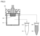
- FIG. 13 is a diagram for explaining the state in which the medium is collected after the end of culture.
- FIG. 1 shows an example of the state of a medium when cells are damaged during culture. 13 is a flow chart illustrating an example of a sample processing step after completion of culture.
- FIG. 11 is a configuration diagram of a cell culture system used in the cell culture method of embodiment 2.
- FIG. 7 is an exploded perspective view of a co-culture device used in the cell culture system of FIG. 6.
- biological cells and microorganisms are collectively referred to as biological elements.
- An example of a biological cell is an organ-forming cell (specifically, an organ-forming cell such as an organoid).
- An example of a microorganism is a fungus or a bacterium.
- FIG. 1 is a configuration diagram of a cell culture system 10 used in the cell culture method of embodiment 1.
- the cell culture system 10 includes a cell culture device 100, a pump 60, culture medium containers 70 and 75, and a measuring device 180.
- the cell culture system 10 is disposed, for example, in an anaerobic chamber, and the surroundings are maintained in an anaerobic environment.
- the cell culture device 100 includes a container body 110, a cell culture insert 120, cover members 130 and 140, and an electrode 150.
- the container body 110 is a container having a substantially cylindrical shape, and has an upper wall 111, a bottom wall 112, and a side wall 113. The side wall 113 connects the upper wall 111 and the bottom wall 112.
- the container body 110 is formed of, for example, a resin material.
- a culture medium 161 (first culture medium) is stored inside the container body 110.
- the inside of the container body 110 is maintained in an atmospheric environment (aerobic environment) by attaching a cell culture insert 120 in which cells (organ-constituting cells) 170 are cultured in a sheet form to the container body 110 in an atmospheric environment.
- the "container body 110" in the embodiment corresponds to the "first chamber” in this disclosure
- the "cell culture insert 120" corresponds to the "second chamber” in this disclosure.
- FIG. 1 shows an example of a configuration in which the upper wall 111 is formed integrally with the side wall 113, the upper wall 111 may be formed as a separate member from the side wall 113.
- An electrode 151 is embedded in the bottom wall 112 of the container body 110.
- the electrode 151 is exposed on the inner and outer surfaces of the bottom wall 112. Inside the container body 110, the electrode 151 is in contact with the culture medium 161, and the electrode 151 and the culture medium 161 can be electrically connected.
- the cell culture insert 120 is a container having a generally cylindrical shape, and has a cylindrical portion 121 forming the side wall of the container, a membrane 122 forming the bottom wall of the container, and a flange portion 123. The lower end of the cylindrical portion 121 is closed by the membrane 122.
- the membrane 122 is formed of an oxygen-permeable material, such as a track-etched membrane made of polycarbonate.
- the membrane 122 may be a porous membrane formed of other materials such as PET (polyethylene terephthalate) or a collagen vitrigel membrane.
- the upper end of the cylindrical portion 121 is open and is sealed by a removable lid member 130.
- a flange portion 123 that protrudes in the outer circumferential direction is provided at the upper end of the cylindrical portion 121.
- the cell culture insert 120 is inserted into the opening 114 of the upper wall 111 of the container body 110. At this time, the flange portion 123 of the cell culture insert 120 is supported by the upper wall 111. The cell culture insert 120 is then fixed to the container body 110 by a removable lid member 140. When the cell culture insert 120 is fixed, the membrane 122 on the underside of the cell culture insert 120 is immersed in the culture medium 161.
- the culture medium 162 is stored inside the cell culture insert 120.
- the dissolved oxygen concentration of the culture medium 162 is lower than the dissolved oxygen concentration of the culture medium 161 in the container body 110. That is, the culture medium 161 is an aerobic culture medium, and the culture medium 162 is an anaerobic culture medium.
- the culture medium 162 contains biological elements.
- the biological elements contained in the culture medium 162 are anaerobic bacteria.
- the anaerobic bacteria may be facultative anaerobes such as lactic acid bacteria, or may be obligate anaerobes such as bifidobacteria.
- the anaerobic bacteria correspond to the "second biological element" in this disclosure.
- Pipes 50 and 55 pass through the cover member 130.
- a pump 60 disposed on pipe 50 introduces culture medium 162 (second culture medium) stored in a culture medium container 70 outside the device into the cell culture insert 120.
- Pipe 55 is a pipe for discharging the culture medium 162 in the cell culture insert 120. Pipe 55 continues to a culture medium container 75 for storing culture medium for disposal. Culture medium 162 that overflows from the cell culture insert 120 is discharged through pipe 55 into the culture medium container 75.
- the biological element is cultured on the inner surface of the membrane 122.
- the biological element is a cell (organ-constituting cell) 170.
- the cell 170 is, for example, an intestinal epithelial cell that forms a tight junction on the membrane 122.
- a specific example of the cell 170 is a Caco-2 cell.
- the membrane 122 is oxygen permeable. Oxygen in the medium 161 is supplied to the cell 170 through the membrane 122. In this way, by co-culturing the cell and bacteria in the anaerobic medium 162, the intestinal environment in a living organism can be simulated.
- the "cell 170" corresponds to the "first biological element" in this disclosure.
- An electrode 150 is further disposed on the cover member 130. Although not shown in FIG. 1, one end of the electrode 150 contacts the culture medium 162 stored in the cell culture insert 120 and is electrically connected to the culture medium 162.
- the electrode 150 disposed on the lid member 130 of the cell culture insert 120 and the electrode 151 embedded in the bottom wall 112 of the container body 110 are connected to a measuring device 180 provided outside the device.
- the measuring device 180 measures the electrical resistance between the electrodes 150 and 151 by applying a voltage between the electrodes 150 and 151.
- the electrical resistance is measured by the measuring device 180, for example, using a four-terminal method.
- the resistance between the electrodes changes depending on whether or not tight junctions are formed in the cells 170 cultured on the membrane 122. Therefore, by monitoring the electrical resistance during culture, it is possible to determine whether or not the tight junctions of the cells 170 are formed normally.
- an oxygen sensor may be provided to detect the dissolved oxygen concentration in culture medium 161 and culture medium 162. By detecting the dissolved oxygen concentration in each culture medium using the oxygen sensor, the growth status of the bacteria during co-culture can be monitored.
- each medium is collected into another container such as an Eppendorf tube and stored for a specified period in a freezer or for subsequent analysis.
- another container such as an Eppendorf tube
- the media collected in the containers have a similar appearance (color)
- the cells and part of the membrane may be damaged, causing one medium to penetrate into the other medium, resulting in the mixing of the aerobic medium and the anaerobic medium.
- the culture process itself will fail.
- the colors of the media during culture are similar, it may not be possible to detect the state in which the media are mixed, and the medium in the failed culture state may end up being analyzed.
- the analytical process is carried out with the medium collected being mixed up and/or the medium being mixed during cultivation, it may lead to erroneous results, which may lead to incorrect judgment of the experimental results and evaluation.
- the aerobic culture medium 161 and the anaerobic culture medium 162 are different colors that can be visually distinguished by the user. This makes it possible to easily determine whether the culture medium is an aerobic culture medium or an anaerobic culture medium after the culture medium is collected in a container such as an Eppendorf tube. Furthermore, by making each culture medium a different color even during cultivation, it is possible to easily detect the mixing of the culture media during cultivation.
- At least one of the two media is colored, and the other may be colorless.
- the media can be colored, for example, using a coloring agent that has little effect on the culture process.
- the color of the medium may be a fixed color that does not change before and after cultivation, or it may change color depending on the condition of the medium. For example, if an indicator that changes color depending on the pH, such as methyl orange, phenolphthalein (PP), or bromothymol blue (BTB), is added to the medium, the color of the medium may change due to changes in the pH of the medium as the cultivation progresses.
- an indicator that changes color depending on the pH such as methyl orange, phenolphthalein (PP), or bromothymol blue (BTB)
- the two media are different in color from the beginning of the culture process; it is sufficient that the two media are different in color at the completion of culture due to the passage of time or changes in the state of the media.
- the media are different in color from the early stages of culture.
- FIG. 2 is a flow chart showing an example of a culture process performed using the cell culture system 10 of FIG. 1. Each process of the flow chart of FIG. 2 may be performed manually by a user, or some or all of the processes may be performed automatically using a handling device (not shown).
- step (hereinafter, step is abbreviated as S) 100 cells are cultured over the entire surface of the membrane 122 in the cell culture insert 120. Then, in S110, the cell culture insert 120 is placed in the opening 114 of the container body 110.
- a first color culture medium 161 is introduced into the container body 110.
- the culture medium 161 is introduced to a height where the membrane 122 on the lower surface of the cell culture insert 120 is immersed in the culture medium 161.
- a second color culture medium 162 containing bacteria is introduced into the cell culture insert 120.
- fresh culture medium 162 is supplied from the culture medium container 70 by the pump 60 into the cell culture insert 120 even during cultivation.
- the culture media 161, 162 used in S120, S130 may be commercially available and already colored. Alternatively, prior to S120, S130, a step of coloring a colorless culture medium using a coloring agent and/or an indicator, etc. may be included.
- the culture medium is introduced into the container body 110 and the cell culture insert 120, in S140, the cells and bacteria are cultured for a predetermined period of time while the electrical resistance and dissolved oxygen concentration are monitored by the measuring device 180.
- FIG. 3 is a diagram for explaining the state in which culture media 161 and 162 are collected after the end of culture.
- FIG. 3 shows the state in which culture media 161 and 162 are different colors at the stage when culture is completed.
- culture medium 161 is shown in a light color
- culture medium 162 is shown in a dark color. Even when culture media 161 and 162 are collected in Eppendorf tubes 210 and 220, respectively, it is possible to distinguish between culture medium 161 and culture medium 162 based on the difference in the color of each culture medium.
- FIG. 4 is a diagram showing an example of the state of the medium when the cell 170 and the membrane 122 are damaged during culture.
- the pressure of the medium 162 is higher than the pressure of the medium 161
- a part of the medium 162 in the cell culture insert 120 leaks into the medium 161 from the damaged area, as shown in region RG in FIG. 4.
- the color of the medium 161 is different from the color of the medium 162
- the medium 162 that has leaked into the medium 161 can be easily detected. Note that when the pressure of the medium 161 is higher than the pressure of the medium 162, if the cell 170 and the membrane 122 are damaged during culture, the medium 161 leaks into the medium 162.
- FIG. 5 is a flow chart for explaining an example of the sample processing process after the end of the culture.
- the processes of S200 to S240 are performed in an anaerobic environment, and the processes of S250 to S280 are performed in an aerobic environment.
- a specific amount of medium 162 which is an anaerobic medium, is collected in a container in an anaerobic environment.
- a specific amount of medium 161 which is an aerobic medium, is collected in a separate container. If necessary, each medium collected in the anaerobic environment is left to stand for a predetermined period of time.
- medium 161 is inoculated onto an agar medium without dilution (S220).
- medium 162 is a medium co-cultured with bacteria, and since it is necessary to count the bacteria, it is diluted and then inoculated onto an agar medium (S230).
- the dilution ratio differs depending on conditions such as the type of bacteria and/or the turbidity of the medium.
- each medium is centrifuged using a centrifuge.
- the supernatant of each medium after centrifugation is transferred to a separate container such as an Eppendorf tube and stored in a specified environment.
- the two culture media are mixed up or mixed during the culture during the sample processing step as shown in FIG. 5, not only will the work up to that point be wasted, but the desired analysis results will not be obtained.
- the culture media can be easily identified after collection, preventing the two culture media from being mixed up. Furthermore, even if the culture media leaks due to cell damage during culture, the leakage state of the culture media can be easily detected, allowing early detection of experimental failures.
- FIG. 6 is a configuration diagram of a cell culture system 10A used in the cell culture method of the second embodiment.
- the cell culture system 10A includes a cell culture device 100A, pumps 60A, 60B, culture medium containers 70A, 70B, 75A, 75B, a measuring device 180, and a sealed container 400.
- the cell culture system 10A is placed, for example, in an anaerobic chamber, and the surroundings are maintained in an anaerobic environment.
- the cell culture device 100A includes a co-culture device 300.
- the co-culture device 300 has two adjacent flow paths 320, 330 formed through a membrane 310.
- the flow path 320 is a path through which an aerobic medium (medium 161) flows
- the flow path 330 is a path through which an anaerobic medium (medium 162) flows.
- Cells 170 are cultured on the surface of the membrane 310 facing the flow channel 320. Oxygen is supplied to the cells 170 from the culture medium 161 flowing through the flow channel 320 via the membrane 310.
- the sealed container 400 is a container whose internal space can be sealed.
- the sealed container 400 includes a main body 410 and a lid member 420.
- the main body 410 has a cylindrical shape with one end closed by a bottom wall and the other end open.
- a removable lid member 420 is attached to the open end of the main body 410.
- the internal space of the sealed container 400 is maintained in an atmospheric environment, i.e., an aerobic environment.
- a medium container 70A in which medium 161 is stored Inside the sealed container 400, there are arranged a medium container 70A in which medium 161 is stored, a pipe 50A, and a pump 60A attached to the pipe 50A.
- the pipe 50A connects the medium container 70A to a flow path 320 of the co-culture device 300.
- the pump 60A By driving the pump 60A, the medium 161 in the medium container 70A is supplied to the flow path 320 through the pipe 50A.
- the medium 161 that has passed through the flow path 320 is discharged through the pipe 55A into the medium container 75A for waste liquid.
- Culture medium 162 is stored in culture medium container 70B, which is placed in the anaerobic environment.
- Culture medium container 70B is connected to flow path 330 of co-culture device 300 by piping 50B.
- By driving pump 60B provided on piping 50B culture medium 162 in culture medium container 70B is supplied to flow path 330 through piping 50B.
- Culture medium 162 that has passed through flow path 330 is discharged through piping 55B to waste culture medium container 75B.
- an electrode 350 is arranged so as to be exposed in the flow path 320, and an electrode 355 is arranged so as to be exposed in the flow path 330.
- the electrode 350 can be electrically connected to the culture medium 161 flowing in the flow path 320, and the electrode 355 can be electrically connected to the culture medium 162 flowing in the flow path 330.
- the electrodes 350 and 355 are connected to a measuring device 180. By applying a voltage to the electrodes 350 and 355 from the measuring device 180, the electrical resistance value between the electrodes 350 and 355 can be monitored.
- an oxygen sensor may be provided to detect the dissolved oxygen concentration in the culture media 161, 162 flowing through each flow path.
- FIG. 7 is an exploded perspective view of the co-culture device 300 used in the cell culture system 10A in FIG. 6.
- the co-culture device 300 includes flat glass plates 301, 302 and flat resin sheets 305, 306 arranged between the glass plates 301, 302.
- the glass plates 301, 302 and the resin sheets 305, 306 are layered in the following order: glass plate 301, resin sheet 305, resin sheet 306, and glass plate 302.
- An example of the resin sheets 305 and 306 is silicone rubber.
- the glass plate and the resin sheet, and the resin sheets are bonded together, for example, by applying pressure to the bonding surfaces in a state where the bonding surfaces are activated by oxygen plasma.
- a through hole 361 is formed in the glass plate 301, penetrating it in the thickness direction.
- a pipe 50A is connected to the through hole 361.
- the through hole 361 serves as the inlet of the flow path 320 through which the culture medium 161 flows.
- a groove 340 is formed on the surface of the resin sheet 305 facing the glass plate 301.
- the flow path 320 in FIG. 6 is formed by this groove 340 and the surface of the glass plate 301.
- One end of the groove 340 is connected to a through hole 361 in the glass plate 301.
- a through hole 362 is formed at the other end of the groove 340, penetrating the resin sheet 305 in the thickness direction.
- Through holes 363, 364 are formed in the resin sheet 306 and the glass plate 302 at positions corresponding to the through hole 362 in the resin sheet 305.
- Pipe 55A is connected to the through hole 364 in the glass plate 302.
- the through hole 364 in the glass plate 302 serves as the outlet of the flow path 320 through which the culture medium 161 flows.
- a groove 380 is formed on the surface of the resin sheet 306 that faces the glass plate 302.
- the groove 380 and the surface of the glass plate 302 form the flow path 330 in FIG. 6.
- a through hole 371 is formed at a position corresponding to one end of the groove portion 380, penetrating in the thickness direction
- a through hole 372 is formed at a position corresponding to the other end of the groove portion 380, penetrating in the thickness direction.
- Pipe 50B is connected to through hole 371 in the glass plate 302.
- Pipe 55B is connected to through hole 372 in the glass plate 302. That is, through holes 371, 372 in the glass plate 302 respectively serve as the inlet and outlet of flow path 330 through which culture medium 162 flows.
- a portion of groove portion 340 formed in resin sheet 305 overlaps in parallel with groove portion 380 formed in resin sheet 306.
- a slit 341 penetrating in the thickness direction is formed in the overlapping portion of resin sheet 305.
- a slit 381 is formed in groove portion 380 of resin sheet 306 at a position opposite slit 341.
- a membrane 310 is disposed between slit 341 and slit 381.
- This configuration realizes a configuration in which two adjacent flow paths 320, 330 are connected via the membrane 310. That is, in the cell culture system 10A used in the cell culture method of embodiment 2, the flow path 320 in FIG. 6 corresponds to the container body 110 of the cell culture system 10 in embodiment 1, and the flow path 330 corresponds to the cell culture insert 120 of the cell culture system 10. That is, the "flow path 320" and the “flow path 330" in embodiment 2 correspond to the "first chamber” and the "second chamber” in the present disclosure, respectively.
- a cell culture method relates to a method for co-culturing a first biological element and a second biological element using a co-culture device.
- the co-culture device includes a first chamber and a second chamber capable of storing a culture medium therein.
- the second chamber separates the first chamber from the second chamber and includes a membrane having oxygen permeability.
- the cell culture method includes the steps of (a) culturing the first biological element inside the second chamber so as to cover the membrane, (b) introducing a first culture medium having a first color into the first chamber, (c) introducing a second culture medium having a second color different from the first color and including a second biological element into the second chamber, and (d) co-culturing the first biological element and the second biological element with the membrane disposed in contact with the first culture medium.
- the second color is a color that can be visually distinguished from the first color by a user.
- the colors of the culture media are made visually distinguishable by the user, so that the two culture media can be easily distinguished.
- the cell culture method described in 1 or 2 further includes a step of coloring the first culture medium a first color and a step of coloring the second culture medium a second color.
- the two media can be easily distinguished by coloring the medium with a coloring agent or the like.
- At least one of the first culture medium and the second culture medium contains an indicator that changes color depending on the state of the medium.
- an indicator that changes color depending on the state of the medium can be used to confirm the change in state of the medium and to easily distinguish the medium after culture by the difference in color.
- the dissolved oxygen concentration of the first culture medium is higher than the dissolved oxygen concentration of the second culture medium.
- the first medium can be used as an aerobic medium
- the second medium can be used as an anaerobic medium
- the second chamber is a cell culture insert that further includes a cylindrical portion and has a membrane disposed so as to close the lower end of the cylindrical portion.
- a cell culture insert that is widely used in general can be used as the second chamber.
- the first biological element is an organ-constituting cell
- the second biological element is a microorganism
- the cell culture method of the present disclosure can be applied to co-culture of organ-constituting cells and microorganisms.
Landscapes
- Health & Medical Sciences (AREA)
- Life Sciences & Earth Sciences (AREA)
- Chemical & Material Sciences (AREA)
- Engineering & Computer Science (AREA)
- Wood Science & Technology (AREA)
- Organic Chemistry (AREA)
- Bioinformatics & Cheminformatics (AREA)
- Zoology (AREA)
- Genetics & Genomics (AREA)
- Biotechnology (AREA)
- Biochemistry (AREA)
- Microbiology (AREA)
- General Engineering & Computer Science (AREA)
- General Health & Medical Sciences (AREA)
- Biomedical Technology (AREA)
- Sustainable Development (AREA)
- Clinical Laboratory Science (AREA)
- General Chemical & Material Sciences (AREA)
- Immunology (AREA)
- Analytical Chemistry (AREA)
- Molecular Biology (AREA)
- Physiology (AREA)
- Cell Biology (AREA)
- Medicinal Chemistry (AREA)
- Tropical Medicine & Parasitology (AREA)
- Virology (AREA)
- Apparatus Associated With Microorganisms And Enzymes (AREA)
Abstract
Description
(細胞培養システムの構成)
図1は、実施の形態1の細胞培養方法に用いられる細胞培養システム10の構成図である。細胞培養システム10は、細胞培養装置100と、ポンプ60と、培地容器70,75と、測定装置180とを備える。細胞培養システム10は、たとえば、嫌気チャンバ内に配置されており、周囲が嫌気環境に保たれている。
実施の形態2においては、細胞培養装置の他の構成の例について説明する。図6は、実施の形態2の細胞培養方法に用いられる細胞培養システム10Aの構成図である。
上述した複数の例示的な実施形態は、以下の態様の具体例であることが当業者により理解される。
Claims (7)
- 共培養装置を用いて第1生物学的要素および第2生物学的要素を共培養する細胞培養方法であって、
前記共培養装置は、内部に培地を貯留可能な第1チャンバおよび第2チャンバを含み、
前記第2チャンバは、前記第1チャンバと前記第2チャンバとを分離するとともに、酸素透過性を有するメンブレンを含み、
前記細胞培養方法は、
前記第2チャンバの内部において前記メンブレンを覆うように前記第1生物学的要素を培養するステップと、
第1色を呈する第1培地を前記第1チャンバ内に導入するステップと、
前記第2生物学的要素を含み、前記第1色とは異なる第2色を呈する第2培地を前記第2チャンバ内に導入するステップと、
前記メンブレンが前記第1培地に接するように配置された状態で、前記第1生物学的要素および前記第2生物学的要素を共培養するステップとを含む、細胞培養方法。 - 前記第2色はユーザが目視により前記第1色と区別可能な色である、請求項1に記載の細胞培養方法。
- 前記第1培地を前記第1色に着色するステップと、
前記第2培地を前記第2色に着色するステップとをさらに含む、請求項1に記載の細胞培養方法。 - 前記第1培地および前記第2培地の少なくとも一方は、培地の状態によって色が変化する指示薬を含む、請求項1に記載の細胞培養方法。
- 前記第1培地の溶存酸素濃度は、前記第2培地の溶存酸素濃度よりも高い、請求項1に記載の細胞培養方法。
- 前記第2チャンバは、筒状部をさらに含み、前記筒状部の下端を閉塞するように前記メンブレンが配置されたセルカルチャインサートである、請求項1に記載の細胞培養方法。
- 前記第1生物学的要素は、器官構成細胞であり、
前記第2生物学的要素は、微生物である、請求項1に記載の細胞培養方法。
Priority Applications (3)
| Application Number | Priority Date | Filing Date | Title |
|---|---|---|---|
| JP2025527549A JPWO2024257513A1 (ja) | 2023-06-15 | 2024-05-09 | |
| EP24823135.9A EP4729601A1 (en) | 2023-06-15 | 2024-05-09 | Cell culture method |
| CN202480038918.7A CN121464209A (zh) | 2023-06-15 | 2024-05-09 | 细胞培养方法 |
Applications Claiming Priority (2)
| Application Number | Priority Date | Filing Date | Title |
|---|---|---|---|
| JP2023-098483 | 2023-06-15 | ||
| JP2023098483 | 2023-06-15 |
Publications (1)
| Publication Number | Publication Date |
|---|---|
| WO2024257513A1 true WO2024257513A1 (ja) | 2024-12-19 |
Family
ID=93851844
Family Applications (1)
| Application Number | Title | Priority Date | Filing Date |
|---|---|---|---|
| PCT/JP2024/017243 Ceased WO2024257513A1 (ja) | 2023-06-15 | 2024-05-09 | 細胞培養方法 |
Country Status (4)
| Country | Link |
|---|---|
| EP (1) | EP4729601A1 (ja) |
| JP (1) | JPWO2024257513A1 (ja) |
| CN (1) | CN121464209A (ja) |
| WO (1) | WO2024257513A1 (ja) |
Citations (4)
| Publication number | Priority date | Publication date | Assignee | Title |
|---|---|---|---|---|
| WO2019193703A1 (ja) * | 2018-04-05 | 2019-10-10 | オリンパス株式会社 | 酸解離平衡推定方法、酸解離平衡推定装置、酸解離平衡推定システム、およびユーザインタフェース装置 |
| US20210079356A1 (en) * | 2018-04-02 | 2021-03-18 | President And Fellows Of Harvard College | Complex Human Gut Microbiome Cultured In An Anaerobic Human Gut-On-A-Chip |
| WO2022009672A1 (ja) | 2020-07-07 | 2022-01-13 | 株式会社島津製作所 | 細胞培養システム |
| JP2022130304A (ja) * | 2021-02-25 | 2022-09-06 | 株式会社島津製作所 | 共培養装置、共培養システム及び共培養方法 |
-
2024
- 2024-05-09 EP EP24823135.9A patent/EP4729601A1/en active Pending
- 2024-05-09 CN CN202480038918.7A patent/CN121464209A/zh active Pending
- 2024-05-09 WO PCT/JP2024/017243 patent/WO2024257513A1/ja not_active Ceased
- 2024-05-09 JP JP2025527549A patent/JPWO2024257513A1/ja active Pending
Patent Citations (4)
| Publication number | Priority date | Publication date | Assignee | Title |
|---|---|---|---|---|
| US20210079356A1 (en) * | 2018-04-02 | 2021-03-18 | President And Fellows Of Harvard College | Complex Human Gut Microbiome Cultured In An Anaerobic Human Gut-On-A-Chip |
| WO2019193703A1 (ja) * | 2018-04-05 | 2019-10-10 | オリンパス株式会社 | 酸解離平衡推定方法、酸解離平衡推定装置、酸解離平衡推定システム、およびユーザインタフェース装置 |
| WO2022009672A1 (ja) | 2020-07-07 | 2022-01-13 | 株式会社島津製作所 | 細胞培養システム |
| JP2022130304A (ja) * | 2021-02-25 | 2022-09-06 | 株式会社島津製作所 | 共培養装置、共培養システム及び共培養方法 |
Non-Patent Citations (1)
| Title |
|---|
| SEN AKIRA, NISHIMURA TATSUKI, YOSHIMOTO SHIN, YOSHIDA KEISUKE, GOTOH AINA, KATOH TOSHIHIKO, YONEDA YASUKO, HASHIMOTO TOYOYUKI, XIA: "Comprehensive analysis of metabolites produced by co-cultivation of Bifidobacterium breve MCC1274 with human iPS-derived intestinal epithelial cells", FRONTIERS IN MICROBIOLOGY, vol. 14, XP093092779, DOI: 10.3389/fmicb.2023.1155438 * |
Also Published As
| Publication number | Publication date |
|---|---|
| CN121464209A (zh) | 2026-02-03 |
| EP4729601A1 (en) | 2026-04-22 |
| JPWO2024257513A1 (ja) | 2024-12-19 |
Similar Documents
| Publication | Publication Date | Title |
|---|---|---|
| JP4066200B2 (ja) | 微生物を検出するデバイスおよび方法 | |
| CN208684959U (zh) | 一种核酸扩增检测微流控芯片 | |
| US8241867B2 (en) | Integrated filtration and detection device | |
| US4318994A (en) | Enterobacteriaceae species biochemical test card | |
| EP1097240B1 (en) | Evacuated sensor device for detecting microorganisms in blood samples, and method therefor | |
| US7781185B2 (en) | Apparatus and method for testing liquid samples | |
| AU1928795A (en) | Apparatus and method for quantification of biological material in a liquid sample | |
| US11623213B2 (en) | Microbiological testing device, method for provision and use of such a device | |
| NO773071L (no) | Fremgangsmaate for identifisering av mikroorganismer, samt hjelpemiddel for fremgangsmaatens utfoerelse | |
| JP2017501720A (ja) | サンプル調製ユニットおよびサンプル調製デバイス | |
| US20130189770A1 (en) | Sample testing device | |
| CA1045530A (en) | Analytical device and method | |
| WO2024257513A1 (ja) | 細胞培養方法 | |
| US10921319B2 (en) | Immunoassay detection device with test strip accommodated in a capillary tube | |
| CA2062811A1 (en) | Apparatus for microbiological testing | |
| US6395537B1 (en) | Double container device and method for detecting and enumerating microorganisms in a sample | |
| JP7416269B2 (ja) | 細胞培養容器及び細胞培養システム | |
| CN104662144A (zh) | 用于生物负载样品收集和检测的可弃容器 | |
| US11060053B2 (en) | Method and device for hydrating a hydrating medium by a liquid sample | |
| US12195709B2 (en) | Co-culture apparatus, co-culture system, and co-culture method | |
| EP4617350A1 (en) | Culture vessel, microorganism culture system, and nucleic acid analysis system | |
| US3553082A (en) | Method and means for detecting coliform bacteria in water | |
| CN220552863U (zh) | 一种用于wb实验的抗体孵育管 | |
| TWI715176B (zh) | 生物檢測卡匣及方法 | |
| CN120665696A (zh) | 培养容器和培养试剂盒以及进行微生物的落下菌检查的方法 |
Legal Events
| Date | Code | Title | Description |
|---|---|---|---|
| 121 | Ep: the epo has been informed by wipo that ep was designated in this application |
Ref document number: 24823135 Country of ref document: EP Kind code of ref document: A1 |
|
| ENP | Entry into the national phase |
Ref document number: 2025527549 Country of ref document: JP Kind code of ref document: A |
|
| WWE | Wipo information: entry into national phase |
Ref document number: 2025527549 Country of ref document: JP |
|
| WWE | Wipo information: entry into national phase |
Ref document number: 2024823135 Country of ref document: EP |
|
| NENP | Non-entry into the national phase |
Ref country code: DE |
|
| ENP | Entry into the national phase |
Ref document number: 2024823135 Country of ref document: EP Effective date: 20260115 |
|
| ENP | Entry into the national phase |
Ref document number: 2024823135 Country of ref document: EP Effective date: 20260115 |
|
| ENP | Entry into the national phase |
Ref document number: 2024823135 Country of ref document: EP Effective date: 20260115 |
|
| ENP | Entry into the national phase |
Ref document number: 2024823135 Country of ref document: EP Effective date: 20260115 |
|
| WWP | Wipo information: published in national office |
Ref document number: 2024823135 Country of ref document: EP |