WO2024257546A1 - ロボットシステム、ロボット制御方法、およびロボット制御プログラム - Google Patents
ロボットシステム、ロボット制御方法、およびロボット制御プログラム Download PDFInfo
- Publication number
- WO2024257546A1 WO2024257546A1 PCT/JP2024/018169 JP2024018169W WO2024257546A1 WO 2024257546 A1 WO2024257546 A1 WO 2024257546A1 JP 2024018169 W JP2024018169 W JP 2024018169W WO 2024257546 A1 WO2024257546 A1 WO 2024257546A1
- Authority
- WO
- WIPO (PCT)
- Prior art keywords
- workpiece
- robot
- work
- information
- skeleton
- Prior art date
- Legal status (The legal status is an assumption and is not a legal conclusion. Google has not performed a legal analysis and makes no representation as to the accuracy of the status listed.)
- Ceased
Links
Images






Classifications
-
- B—PERFORMING OPERATIONS; TRANSPORTING
- B25—HAND TOOLS; PORTABLE POWER-DRIVEN TOOLS; MANIPULATORS
- B25J—MANIPULATORS; CHAMBERS PROVIDED WITH MANIPULATION DEVICES
- B25J9/00—Program-controlled manipulators
- B25J9/16—Program controls
- B25J9/1694—Program controls characterised by use of sensors other than normal servo-feedback from position, speed or acceleration sensors, perception control, multi-sensor controlled systems, sensor fusion
- B25J9/1697—Vision controlled systems
-
- B—PERFORMING OPERATIONS; TRANSPORTING
- B25—HAND TOOLS; PORTABLE POWER-DRIVEN TOOLS; MANIPULATORS
- B25J—MANIPULATORS; CHAMBERS PROVIDED WITH MANIPULATION DEVICES
- B25J19/00—Accessories fitted to manipulators, e.g. for monitoring, for viewing; Safety devices combined with or specially adapted for use in connection with manipulators
- B25J19/02—Sensing devices
- B25J19/021—Optical sensing devices
- B25J19/023—Optical sensing devices including video camera means
-
- B—PERFORMING OPERATIONS; TRANSPORTING
- B25—HAND TOOLS; PORTABLE POWER-DRIVEN TOOLS; MANIPULATORS
- B25J—MANIPULATORS; CHAMBERS PROVIDED WITH MANIPULATION DEVICES
- B25J9/00—Program-controlled manipulators
- B25J9/16—Program controls
- B25J9/1656—Program controls characterised by programming, planning systems for manipulators
- B25J9/1661—Program controls characterised by programming, planning systems for manipulators characterised by task planning, object-oriented languages
-
- B—PERFORMING OPERATIONS; TRANSPORTING
- B25—HAND TOOLS; PORTABLE POWER-DRIVEN TOOLS; MANIPULATORS
- B25J—MANIPULATORS; CHAMBERS PROVIDED WITH MANIPULATION DEVICES
- B25J9/00—Program-controlled manipulators
- B25J9/16—Program controls
- B25J9/1656—Program controls characterised by programming, planning systems for manipulators
- B25J9/1664—Program controls characterised by programming, planning systems for manipulators characterised by motion, path, trajectory planning
-
- G—PHYSICS
- G05—CONTROLLING; REGULATING
- G05B—CONTROL OR REGULATING SYSTEMS IN GENERAL; FUNCTIONAL ELEMENTS OF SUCH SYSTEMS; MONITORING OR TESTING ARRANGEMENTS FOR SUCH SYSTEMS OR ELEMENTS
- G05B2219/00—Program-control systems
- G05B2219/30—Nc systems
- G05B2219/40—Robotics, robotics mapping to robotics vision
- G05B2219/40053—Pick 3-D object from pile of objects
Definitions
- One aspect of the present disclosure relates to a robot system, a robot control method, and a robot control program.
- Robots that handle food, agricultural products, and other items have been developed for some time.
- one aspect of this disclosure aims to improve the reliability of work performed on a workpiece.
- a robot system includes a skeleton estimation unit that estimates skeleton information indicating the skeleton of a workpiece based on a workpiece image including the workpiece existing in real space, a completion state determination unit that determines the completion state of work performed on the workpiece based on constraint condition information indicating constraint conditions related to work on the workpiece and the estimated skeleton information, and a robot control unit that causes a robot positioned in real space to perform work according to the determined completion state.
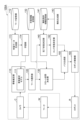
- FIG. 1 is a diagram illustrating an example of a configuration of a robot system.
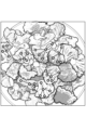
- FIG. 2 is a diagram showing a workpiece and its skeletal information.
- FIG. 2 is a diagram showing a workpiece and its skeletal information.
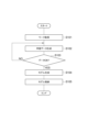
- FIG. 11 is a diagram illustrating an example of the operation of the robot system.
- FIG. 11 is a diagram illustrating an example of the operation of the robot system.
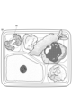
- FIG. 13 is a diagram for explaining the results of the operation of the robot system.
- FIG. 13 is a diagram for explaining the results of the operation of the robot system.
- FIG. 2 is a diagram illustrating an example of a hardware configuration of a computer used for the robot system.
- FIG. 13 is a diagram showing a configuration of a robot system according to a modified example.
- FIG. 13 is a diagram showing an example of estimated workpiece keypoints.
- FIG. 11 illustrates an example of a process for selecting a workpiece.
- FIG. 13 is a diagram showing an example of a processed workpiece.
- 13 is a diagram showing a configuration of a robot system according to a modified example.
- FIG. 13 is a diagram illustrating an example of a user interface for generating constraint condition information.
- FIG. 1 is a diagram showing an example of the configuration of the robot system 100.
- Fig. 2A and Fig. 2B are both diagrams showing a workpiece W and skeletal information K of the workpiece W.
- the robot system 100 is a control system for causing a robot R placed in real space to process a workpiece W present in the real space.
- the robot system 100 includes a camera C, a skeleton estimation unit 110, a workpiece memory unit 112, a learning data generation unit 113, a learning unit 114, a workpiece selection unit 120, a start state determination unit 130, a work information memory unit 132, a completion state determination unit 140, a constraint condition information memory unit 141, an end state determination unit 142, a path generation unit 150, a robot control unit 160, and a robot R.
- the robot R is a device or equipment that performs work on a workpiece W.
- the robot R is placed in real space.
- the robot R has an end effector that applies the action required for that work to the workpiece W.
- the robot R is a vertical articulated robot, but the robot R may also be other types of robots, such as a horizontal articulated robot or a cartesian machine.
- the operation refers to a process performed by the robot R on the workpiece W.
- the operation can be a process that affects the shape of the workpiece W.
- the operation includes at least one of handling the workpiece W and processing the workpiece W.
- handling include pick-and-place, alignment, packing, unpacking, and assembly.
- processing include welding, painting, grinding, polishing, cutting, and printing.
- the robot system 100 can cause the robot R to perform work on various workpieces W.
- the robot system 100 causes the robot R to perform work on an irregular workpiece W.
- the irregular workpiece W can be broccoli, fried shrimp, fried chicken, and other workpieces that are difficult to deform but have individual differences in shape.
- the irregular workpiece W can be a flexible object, such as a harness, cable, or handkerchief, in which the individual differences in shape can be ignored but the difference in the degree of deformation between individual objects can be large.
- the irregular workpiece W can be a workpiece that combines the characteristics of these two types of workpieces. Broccoli is shown in Figure 2A as an example of an irregular workpiece W that has individual differences in shape.
- the camera C captures an image of the workpiece W and generates a workpiece image that is an image that includes the workpiece W (i.e., an image that captures the workpiece W).
- the image may be a two-dimensional image, or may include a distance image in addition to the two-dimensional image.
- the camera C is fixed to the tip of the arm of the robot R.
- the camera C may be fixed to another position on the robot R, or may be fixed to the ceiling or a pillar. Multiple cameras C may be arranged.
- the skeleton estimation unit 110 is a functional module that estimates skeleton information K that indicates the skeleton of the workpiece W based on an image including the workpiece W.
- the skeleton information K indicates the skeleton of the workpiece W to the extent that work on the workpiece W by the robot R can be planned.
- the skeleton of the workpiece W represents the external shape of the workpiece W or the approximate positional relationship of the parts of the workpiece W.
- the workpiece W does not need to have a "bone.”
- broccoli has a structure in which multiple stalks extend from one stalk and each stalk is connected to a bunch.
- the skeleton information K indicates the approximate positional relationship of such parts to the extent that the robot R can perform work on the broccoli.
- the skeletal information K of the work W includes multiple keys, which are information for indicating the approximate positional relationship of parts of the work W.
- the multiple keys include multiple key points, which are information indicating the positions of specific parts of the work W, and one or more skeletons, each of which is a virtual line connecting two key points.
- a skeleton is also called a bone.
- the skeletal information K of the work W includes multiple keys, which include multiple key points P (P1 to P5) and multiple skeletons S (S1 to S4) of the work W.
- the skeleton estimation unit 110 can estimate the skeletal information K for each of the two or more works W.
- the skeleton estimation unit 110 estimates the skeleton information K of the workpiece W using the skeleton estimation model 111.
- the skeleton estimation model 111 is an inference device that accepts an input of a workpiece image including the workpiece W and estimates the skeleton information K of the workpiece W.
- the skeleton estimation unit 110 estimates the skeleton information K by inputting the workpiece image of the workpiece W for which the skeleton information K is to be estimated to the skeleton estimation model 111.
- the skeleton estimation model 111 can be realized using keypoint detection technology such as OpenPose, RTMPoses, and YOLOX-Pose.
- a keypoint P the position of a specific part of the recognition target of the workpiece W is identified as a keypoint P, and a virtual line (edge) that represents the relationship between the two positions is inferred as a skeleton S (bone).
- skeleton S a virtual line that represents the relationship between the two positions.
- the skeleton estimation model 111 is generated in advance by machine learning using learning data including a sample image, which is an image based on a three-dimensional model (3D model) of the work W, and a plurality of data records in which a plurality of keys set in the 3D model are associated with each other. Therefore, the skeleton estimation model 111 is a trained model.
- the multiple keys in each data record also include a plurality of key points and one or more skeletons, each of which connects two key points.
- the robot system 100 has a work memory unit 112, a training data generation unit 113, and a learning unit 114 as components for performing the learning.
- the work storage unit 112 is a functional module that stores at least one sample image based on a 3D model of the work W and skeletal information K of each 3D model as learning data.
- the learning data generation unit 113 is a functional module that transforms a 3D model indicated by at least one of the multiple data records of the learning data stored in the work storage unit 112 to generate a new data record of the learning data, and stores the new data record in the work storage unit 112.
- the skeletal information K of the original 3D model is known, the skeletal information K (multiple keys) of the transformed 3D model can be determined. Therefore, a new data record in which the transformed 3D model and the determined skeletal information K are associated with each other can be stored in the work storage unit 112.
- the learning data generation unit 113 can increase the learning data by such processing.
- the transformation of the 3D model may include not only a process of changing the outer shape of the 3D model to give individual differences in the outer shape of the work W, but also a process of giving individual differences in the degree of deformation of the 3D model of an item that is flexible and therefore deformable.
- the learning unit 114 is a functional module that trains the skeleton estimation model 111 by machine learning using learning data that may include new data records, and generates the skeleton estimation model 111.
- the generation of the skeleton estimation model 111 by the learning unit 114 may include updating the skeleton estimation model 111.
- the work selection unit 120 is a functional module that selects at least one work W to be processed in the work based on skeletal information K estimated for each of the multiple work pieces W included in the work image. If the work image includes a single work piece W, the work selection unit 120 selects that work piece W. As shown in FIG. 2B, the work image may include multiple work pieces W. In this case, the work selection unit 120 selects at least one work piece W to be processed in the work from the work image.
- the work selection unit 120 selects at least one work based on the skeletal information K of each of the multiple workpieces W.
- the work selection unit 120 may select a workpiece W having skeletal information K with a degree of deformation within a predetermined range, such as a straight workpiece W or a workpiece W with a small degree of bending.
- the work selection unit 120 may select the current workpiece W based on its relationship with previously selected workpieces W so that the variation in the skeletal information K of the workpieces W to be processed successively falls within a predetermined threshold value.
- the work selection unit 120 calculates the area on the work image for each of the multiple workpieces W. Then, based on the area and skeletal information K of each of the multiple workpieces W, the work selection unit 120 selects a workpiece that is entirely exposed in the work image without being hidden or buried by other workpieces W. Based on the area and skeletal information K of each of the multiple workpieces W, the work selection unit 120 may select a workpiece W whose skeletal information K is entirely exposed, or a workpiece W whose proportion of exposed skeletal information K is equal to or greater than a predetermined threshold value.
- the start state determination unit 130 is a functional module that determines the start state, which is the state of the robot R at the start of work, based on the skeletal information K of the workpiece W.
- the start state represents, for example, at least one of the position and posture of the robot R when work on the workpiece W is started.
- the position and posture of the robot R may be the position and posture of the end effector.
- the start state represents, for example, the position and posture of the end effector when picking up the workpiece W.
- the start state represents, for example, the position and posture of the end effector at the start of the process.
- the start state determination unit 130 may analyze the skeletal information K of the workpiece W, convert the skeletal information K into at least one of the position and posture of the end effector when the end effector acts on the workpiece W (e.g., picks it), and determine the result of the conversion as the start state.
- the start state determination unit 130 may perform the conversion using a function that receives input of the skeletal information K and calculates the start state, or may geometrically analyze the skeletal information K to extract the start state.
- the start state determination unit 130 may perform the conversion using an inference unit that receives input of at least the skeletal information K and outputs the start state.
- the start state determination unit 130 may simulate various start states based on the skeletal information K, evaluate each simulation result using a predetermined evaluation method, and determine the start state that will give the optimal simulation result.
- the start state determination unit 130 may determine the start information based on the work information that is set according to the type of work W or the work and stored in the work information storage unit 132, and the estimated skeletal information K.
- the work information is defined for each type of work W, regardless of individual differences such as the shape of the work W, and is associated with at least one of a plurality of keys of the work W.
- the work information represents information regarding the work performed on the work W.
- the work information includes at least one of the position and the posture of the end effector acting on the work W in the start state of the work performed on the work W.
- the operation information includes pick information indicating whether or not the robot R can pick a position on the workpiece W corresponding to at least one key of the workpiece W.
- the pick information may indicate whether or not the robot R can pick the periphery of each of the key points P and skeletons S.
- the start state determination unit 130 determines the pick position A of the workpiece W by the robot R as the start state based on the pick information and the estimated skeleton information K.
- the pick position A refers to the position at which the robot R acts on the workpiece W to pick it.
- the pick position A indicates the gripping position
- the pick position A indicates the suction position.
- the operation information may indicate whether or not processing can be started around each of the multiple keys (each key point P and each skeleton S) of the workpiece W.
- the completion state determination unit 140 is a functional module that determines the completion state of the work performed on the workpiece W based on the constraint condition information that represents the constraint conditions related to the work on the workpiece W and the estimated skeletal information K.
- the robot system 100 causes the robot R to perform the work according to the determined completion state.
- the constraint conditions represent conditions related to the work on the workpiece W, and are stored in advance as constraint condition information in the constraint condition information storage unit 141.
- the constraint conditions are specified for each type of workpiece W, regardless of individual differences such as the shape of the workpiece W.
- the constraint conditions include conditions for the state of one or more workpieces W after the work is completed for each of multiple types of workpieces W. If the work is handling, the constraint conditions may be conditions for the posture (e.g., orientation) of each workpiece W, conditions for the evaluation result in a state in which one or more workpieces W are arranged or aligned, or conditions for the state of the workpieces W after assembly is completed.
- the evaluation result may be calculated by applying physical measurements of one or more arranged or aligned workpieces W to a predetermined algorithm, or may be calculated by inputting an image of one or more arranged or aligned workpieces W into a trained model such as a neural network. If the work is processing, the constraint conditions may be conditions for the state of one or more workpieces W after the processing is completed.
- the completion state represents the predicted state of a specific workpiece W processed by the work to be performed by the robot R when the work to be performed is completed.
- the constraint conditions are defined for each type of workpiece W, regardless of individual differences such as the shape of the workpiece W, whereas the completion state is defined according to the shape of the individual workpiece W to be processed by the work to be performed.
- the constraint conditions may be a condition that a specific part of the workpiece W is placed in a specific direction, or a condition regarding the evaluation value of the state in which multiple workpieces W are placed.
- the completion state determination unit 140 may determine, as the completion state, a post-placement state, which is a state after the workpiece W has been placed, according to the individual shape of the workpiece W (i.e., the skeletal information K).
- the completion state determination unit 140 may at least determine the posture (e.g., orientation) of the placed workpiece W as the post-placement state, and may further determine at least one of the position and shape of the placed workpiece W.
- the completion state determination unit 140 determines at least the posture of the placed work W by specifying not only the direction of a specific part of the work W but also the direction of other parts, and further determines at least one of the position and shape of the placed work W.
- the completion state determination unit 140 may convert the constraint condition information into a value or condition specific to the individual work W to be processed using the estimated skeletal information K, and determine the conversion result as the completion state. For example, if the constraint condition information specifies the position and direction of a specific part of the work W, the completion state determination unit 140 identifies a specific part of the work W from the estimated skeletal information K, and specifies the position and direction of the individual work W so that the specified part is in the position and direction specified by the constraint condition information. Then, the completion state determination unit 140 determines the state of the work W arranged at the specified position and direction as the completion state.
- the completion state determination unit 140 may determine the completion state using a function that receives input of the skeletal information K and calculates the completion state based on the constraint condition information, or may extract the completion state by geometrically analyzing the skeletal information K based on the constraint condition information. As another example, the completion state determination unit 140 may determine the completion state using an inference device that receives input of at least the constraint condition information and the skeletal information K and outputs the completion state. Alternatively, the completion state determination unit 140 may simulate various completion states based on the skeleton information K and the constraint condition information, evaluate each simulation result using a predetermined evaluation method, and determine the completion state that produces the optimal simulation result.
- the robot system 100 causes the robot R to perform a task corresponding to the determined completion state.
- the task corresponding to the completion state is a task that transitions the state of the workpiece W to the completion state, in which case the robot system 100 can achieve the completion state as a result of the task.
- the robot system 100 can also achieve the completion state by determining the start state of the task.
- the robot system 100 may determine an individual welding start position for the workpiece W as the completion state based on the constraint condition in accordance with individual differences in the workpiece W, and cause the robot R to start the task from that welding start position.
- the end state determination unit 142 is a functional module that determines an end state, which is the state of the robot R in a determined completion state, based on the determined completion state. If the robot R can be operated by the completion state without using the end state, the process of determining the end state may be omitted. In this case, the end state can be appropriately interpreted as the completion state. Examples of cases where an end state is unnecessary include a case where the completion state directly represents the end state, and a case where the operation of the robot R is uniquely determined by determining the completion state.
- the end state represents at least one of the position and posture of the robot R when the operation on the workpiece W is completed.
- the position and posture of the robot R may be the position and posture of the end effector.
- the end state represents the position and posture of the end effector when placing the workpiece W.
- the end state represents the position and posture of the end effector when the process is completed.
- the end state determination unit 142 may convert the completion state of the workpiece W based on the configuration of the robot R or the end effector, identify either the position and posture of the tip of the arm of the robot R or the end effector, and determine the identified result as the end state.
- the scope of this disclosure also includes cases where the completion state of the workpiece W is determined indirectly rather than explicitly, that is, where the completion state determination unit 140 and the end state determination unit 142 are integrated into a series of processes, and the end state is determined as if from the constraint condition information and the skeleton information K.
- the path generating unit 150 is a functional module that generates a path for the robot R based on the determined start state and end state.
- the generation of a path is also called a path plan.
- a path represents, for example, the trajectory of the movement of the robot R from the starting point to the end point.
- the path generating unit 150 may collect information on the surrounding environment, such as obstacles, in addition to the start state and end state, and generate a path that prevents the robot R and the transported object from interfering with the obstacles. In the case of pick-and-place, the transported object is a workpiece W.
- the path generating unit 150 may also generate a path using other methods.
- At least one of the start state and the end state may include a predetermined motion of the robot R that is uniquely determined by that state, and the predetermined motion may include an approach point.
- the path generating unit 150 may generate a path from the approach point or a path to the approach point.
- the path generating unit 150 may execute at least one of the end state determination unit 142 redetermining the end state and the start state determination unit 130 redetermining the start state, and generate (regenerate) a path based on at least one of the redetermined end state and the redetermined start state.
- the path generating unit 150 may plan to change the grip of the workpiece W during the process of generating or regenerating a path for a specified task such as pick-and-place. As an example, consider a case where the robot system 100 temporarily places the workpiece W on a placement table, changes the way the workpiece W is held, and continues the pick-and-place.
- the robot system 100 may process, as pick-and-place, the task of transporting the workpiece W to the placement table and the task of transitioning the workpiece W placed on the placement table to a completed state.
- the robot system 100 may divide the task of directly transitioning the workpiece W to the completed state into the task of placing the workpiece W on the placement table and the task of transitioning the workpiece W placed on the placement table to the completed state, and generate a path for each of the divided tasks.
- the robot control unit 160 is a functional module that causes the robot R to perform a task corresponding to the determined completion state. For example, the robot control unit 160 controls the robot R so that the robot R performs a task of transitioning the workpiece W to a completion state using an end effector.
- the robot control unit 160 may cause the robot R to perform a task corresponding to the completion state based on at least one of a start state and an end state.
- the robot control unit 160 causes the robot R to perform a task based on a path generated based on the start state and the end state.
- the robot control unit 160 may cause the robot R to perform a task based on a path generated (regenerated) based on at least one of a redetermined start state and a redetermined end state.
- Such robot control allows a task to be performed according to the skeletal information K of the workpiece W, thereby improving the accuracy or reliability of the task performed on the workpiece W and increasing the variety of workpieces W processed by the robot R.
- FIG. 3A is a diagram showing an example of the operation of the robot system 100 related to learning the skeleton estimation model 111.
- Figure 3B is a diagram showing an example of the operation of the robot system 100 related to the control of the robot R.
- the robot system 100 executes the processes shown in Figures 3A and 3B.
- Figures 4A and 4B are diagrams for explaining the results of the operation of the robot system 100.
- step S101 the learning data generation unit 113 acquires a 3D model and skeleton information K for a specific workpiece W that corresponds to the type of workpiece to be estimated by the skeleton estimation model 111.
- the learning data generation unit 113 acquires a 3D model of the workpiece W based on a sample image stored in the work storage unit 112, and acquires skeleton information K that corresponds to the sample image.
- This skeleton information K includes a plurality of keys set in the 3D model.
- the multiple keys include a plurality of key points and one or more skeletons that each connect two key points.
- the learning data generation unit 113 generates a new data record of the learning data.
- the learning data generation unit 113 deforms the acquired 3D model of the work W, updates the skeletal information K (multiple keys) corresponding to the deformed 3D model, and generates a new sample image obtained from the deformed 3D model.
- the learning data generation unit 113 associates the new sample image with the updated skeletal information K (multiple keys) to generate a new data record.
- the learning data generation unit 113 stores the new data record in the work memory unit 112 as at least a part of the learning data.
- step S103 the learning unit 114 checks whether the amount of learning data required for learning the skeletal estimation model 111 has been prepared. If the amount of learning data is insufficient, the process returns to step S102, and the learning data generation unit 113 further generates new data records. If a sufficient amount of learning data has been prepared, the process proceeds to step S104.
- step S104 the learning unit 114 generates a skeletal estimation model 111 through machine learning using the training data.
- step S105 the learning unit 114 stores the generated skeletal estimation model 111 in the skeletal estimation unit 110.
- learning data can be prepared by deforming a 3D model of the workpiece W, and the skeleton estimation model 111 can be trained using the learning data. Since the amount of learning data required for learning can be prepared without having to manually create a large number of 3D models, the construction costs of the robot system 100 can be reduced.
- step S201 the camera C captures a workpiece image including the workpiece W.
- the camera C captures a workpiece image as shown in FIG. 2B.
- step S202 the skeleton estimation unit 110 estimates skeleton information K of the workpiece W included in the workpiece image.
- the skeleton estimation unit 110 estimates skeleton information K for each of the multiple workpieces (broccoli) W in the workpiece image.
- step S203 the work selection unit 120 selects a work W to be processed in the next operation based on the skeletal information K of each of the one or more works W.
- step S204 the start state determination unit 130 determines pick position A as the start state.
- broccoli near the top center is selected, and the start state determination unit 130 determines pick position A for the selected broccoli.
- step S205 the completion state determination unit 140 determines the completion state of the work performed on the selected work W.
- FIGS. 4A and 4B show examples of the completion state of the work. In these examples, the work is assumed to be pick-and-place of the work (broccoli) W.
- FIG. 4A shows a state in which the broccoli are placed so that their orientations are not uniform
- FIG. 4B shows a state in which the broccoli are placed so that their orientations are uniform.
- the completion state determination unit 140 determines a state in which the orientations of the left and right broccoli are uniform as the completion state when placing the left broccoli shown in FIG. 4B.
- the completion state determination unit 140 determines the position and posture of the left broccoli after placement so that the orientations of the left and right broccoli are uniform.
- step S206 the end state determination unit 142 determines the end state of the robot R in the determined completion state.
- step S207 the path generation unit 150 generates a path connecting the start state and the end state. As a result, it is determined that the robot R picks up the workpiece W in the start state and places the workpiece W in the end state, and a path connecting the start state and the end state is prepared.
- step S208 it is confirmed whether the path generation unit 150 was able to generate a path. If the path cannot be generated, the process returns to step S204. In this case, at least one of the end state determination unit 142 redetermines the end state and the start state determination unit 130 redetermines the start state, and the path generation unit 150 generates (regenerates) a path based on at least one of the redetermined end state and the redetermined start state. If the path can be generated, the process proceeds to step S209.
- step S209 the robot control unit 160 causes the robot R to perform the task corresponding to the determined completion state. If the task is pick-and-place, the robot R picks up the workpiece W in the determined start state, transports the workpiece W along the generated path, and places the workpiece W in the determined end state. In the example of FIG. 4B, even if the workpiece W has an irregular shape such as broccoli, the robot system 100 picks and places each workpiece W so that the orientation of the multiple workpieces W is aligned. This mechanism makes it possible to improve the quality of the task and increase the types of workpieces that can be processed.
- step S210 the work selection unit 120 checks whether or not there is a work W to be processed in the next task (i.e., whether or not the task is to be repeated). If such a work W exists, the robot system 100 repeats the process from step S201 or step S203. If such a work W does not exist, the robot system 100 ends the process.
- the above-mentioned series of processes may be executed by dedicated hardware or software.
- the series of processes is executed by software, the above-mentioned series of processes can be realized by causing a general-purpose or dedicated computer to execute a program.
- the computer may have a CPU (Central Processing Unit), a recording device such as a HDD (Hard Disk Drive), a ROM (Read Only Memory), or a RAM (Random Access Memory), a communication device connected to a network such as a LAN (Local Area Network) or the Internet, an input device such as a mouse or a keyboard, a drive for reading and writing removable storage media such as a magnetic disk such as a flexible disk, various optical disks such as CDs (Compact Discs), MO (Magneto Optical) disks, and DVDs (Digital Versatile Discs), and semiconductor memories, and an output device such as a display device such as a monitor, and an audio output device such as a speaker or headphones.
- This computer may execute the above series of processes by executing a program recorded on a recording device or a removable storage medium, or a program acquired via a network.
- FIG. 5 is a diagram showing an example of the hardware configuration of a computer 1000 used for a robot system according to the present disclosure.
- the computer 1000 includes a main body 1100, an output device 1200, and an input device 1300.
- the main body 1100 is a device having a circuit 1600.
- the circuit 1600 has a processor 1601, a memory 1602, a storage 1603, an input/output port 1604, and a communication port 1605.
- the number of each hardware component may be one or more.
- the storage 1603 records a program for configuring each functional module of the main body 1100.
- the storage 1603 is a computer-readable recording medium such as a hard disk, a non-volatile semiconductor memory, a magnetic disk, or an optical disk.
- the memory 1602 temporarily stores a program loaded from the storage 1603, the calculation results of the processor 1601, etc.
- the processor 1601 configures each functional module by executing a program in cooperation with the memory 1602.
- the input/output port 1604 inputs/outputs an electrical signal between the output device 1200 or the input device 1300 in response to a command from the processor 1601.
- the input/output port 1604 may input/output an electrical signal between another device.
- the communication port 1605 performs data communication with other devices via the communication network N according to instructions from the processor 1601.
- the output device 1200 is a device for outputting information from the main body 1100.
- Examples of the output device 1200 include display devices such as various displays and speakers.
- the input device 1300 is a device for inputting information to the main body 1100.
- Examples of the input device 1300 include operation interfaces such as a keypad, a mouse, and an operation controller.
- the output device 1200 and the input device 1300 may be integrated as a touch panel.
- the main body 1100, the output device 1200, and the input device 1300 may be integrated as in a tablet computer.
- Each functional module of the robot system is realized by loading a robot control program onto the processor 1601 or memory 1602 and having the processor 1601 execute the program.
- the robot control program includes code for realizing each functional module of the robot system.
- the processor 1601 operates the input/output port 1604 and the communication port 1605 in accordance with the robot control program, and executes reading and writing of data in the memory 1602 or the storage 1603.
- the robot control program may be provided in a form recorded on a non-transitory recording medium such as a CD-ROM, DVD-ROM, or semiconductor memory.
- the robot control program may be provided via a communications network as a data signal superimposed on a carrier wave.
- the start state determination unit 130 determines the pick position A as the start state based on the skeleton information K, but the start state determination unit may determine the pick position A directly from the workpiece image. This modified example will be described with reference to FIG.
- FIG. 6 is a diagram showing the configuration of a robot system 200 according to a modified example.
- the robot system 200 differs from the robot system 100 in that it includes a start state determination unit 230 instead of the start state determination unit 130. A description of the same configuration as the robot system 100 will be omitted.
- the start state determination unit 230 has a pick position estimation model 231.
- the pick position estimation model 231 is generated in advance by machine learning using learning data including a plurality of data records. Each data record indicates a correspondence between a sample image based on a 3D model of the work W and pick information indicating whether or not the robot R can pick a position on the 3D model corresponding to a key set in the 3D model.
- the pick information is associated with at least one of a plurality of keys set in the 3D model.
- the plurality of keys includes a plurality of key points P and one or more skeletons S each connecting two key points P.
- the pick position estimation model 231 is learned by the pick information associated with the keys as learning data.
- the pick position estimation model 231 accepts input of a work image including the work W, it processes the work image without using a key and outputs the pick position A. Therefore, the start state determination unit 230 inputs the work image to the pick position estimation model 231 to determine the pick position A of the work W by the robot R.
- the pick position estimation model 231 may be realized, for example, by a neural network model such as CNN.
- the robot control unit 160 causes the robot R to perform a task on the workpiece W based on the end state and the pick position.
- the workpiece processed by the robot may be a flexible object in which the individual difference in shape can be ignored but the difference in the degree of deformation between the individual objects may be large.
- the skeleton estimation unit 110 may estimate a number of key points of the workpiece, calculate scores for the number of key points, and estimate the posture (e.g., orientation) of the workpiece as at least a part of the skeleton information based on the scores.
- FIG. 7 is a diagram showing an example of key points P of the workpiece W estimated using the skeleton estimation model 111.
- the skeleton estimation unit 110 estimates the orientation of the workpiece W as at least a part of the skeleton information. This estimation is also called head-tail determination.
- the workpiece W is a conversion cable for transmitting signals between input/output terminals with different specifications.
- the skeleton estimation model 111 is assumed to have been trained to estimate up to five key points P for the workpiece W. In estimating the key points P, the skeleton estimation model 111 sets an identifier for each key point P to distinguish each individual key point P.
- the skeleton estimation model 111 estimates five key points P with identifiers 0 to 4 in order from the input/output terminal on the head side (the terminal on the right side in FIG. 7) to the input/output terminal on the rear side (the terminal on the left side in FIG. 7), which is an ideal estimation.
- the skeleton estimation model 111 estimates only four key points P, and the identifiers are not arranged in order along the extension direction of the workpiece W.
- the skeleton estimation unit 110 performs processing to accurately perform head-to-tail determination even when the skeleton estimation model 111 does not accurately estimate the key point P, as in situation 302.
- the skeleton estimation unit 110 defines a weight corresponding to an identifier for each of a plurality of key points P that can be detected in advance.
- the skeleton estimation unit 110 also sets a status for each key point P indicating whether or not the key point has been detected. The status is 1 if the key point has been detected, and 0 if the key point has not been detected.
- the skeleton estimation unit 110 divides the work W into two regions based on the midpoint of the line segment connecting the first end and the second end of the work W, and determines in which of the two divided regions each detected key point P is located.
- the skeleton estimation unit 110 For each of a plurality of key points P that can be detected, the skeleton estimation unit 110 calculates the product of the weight, the status, and a predetermined area value assigned to the divided region in which the key point P is located. Then, the skeleton estimation unit 110 calculates a score based on the sum of multiple products corresponding to the plurality of key points P. If the score satisfies a predetermined condition, the skeleton estimation unit 110 determines that the first end is a head-side input/output terminal, and if the score does not satisfy the predetermined condition, the skeleton estimation unit 110 determines that the second end is a head-side input/output terminal.
- the skeleton estimation unit 110 estimates the identifier and position of each of the multiple key points P of the workpiece W.
- the skeleton estimation unit 110 then calculates a score based on the identifier and position of each of the multiple key points P, and estimates the posture of the workpiece W as at least a part of the skeleton information based on the score.
- the work selection unit 120 may use the score to select at least one work from the multiple works included in the work image.
- the skeleton estimation unit 110 calculates a score for each of the multiple works. Based on the score of each of the multiple works, the work selection unit 120 selects at least one work as a work to be processed in the operation. For example, the work selection unit 120 may select a work whose score is equal to or greater than a predetermined threshold value, or may select a work whose score is the highest.
- FIG. 8 is a diagram showing an example of the work selection process.
- the work image G includes multiple workpieces (conversion cables) W stored in a box.
- the skeleton estimation unit 110 calculates a score for each of the multiple workpieces W, and performs head/tail determination for each workpiece W.
- the work selection unit 120 selects the workpiece W located at the top of the box, i.e., the workpiece W located closest to the camera C, based on the scores of the multiple workpieces W.
- the results of the head/tail determination for the selected workpiece W are shown by the labels "head" and "tail", respectively.
- the robot system 100, 200 may check the processed workpiece.
- the camera C photographs and acquires a new workpiece image including the workpiece processed in the work performed by the robot R.
- the skeleton estimation unit 110 estimates new skeleton information indicating the skeleton of the workpiece based on the new workpiece image.
- the completion state determination unit 140 determines whether the processed workpiece satisfies the constraint condition based on the new skeleton information. If the processed workpiece satisfies the constraint condition, the robot system 100, 200 determines whether to have the robot R perform work on another workpiece. This process corresponds to step S210 described above.
- the robot control unit 160 may have the robot R perform work again according to the new skeleton information so that the workpiece satisfies the constraint condition.
- the completion state determination unit 140 may notify the user of the robot system 100, 200 of a message indicating that the constraint condition is not satisfied.
- the constraint conditions include a condition that the work (conversion cable) W is placed within the placement area D.
- the skeleton estimation unit 110 estimates new skeleton information K including multiple key points P of the processed work W.
- the completion state determination unit 140 judges whether the work W satisfies the constraint conditions based on the skeleton information K. For example, the completion state determination unit 140 judges that the constraint conditions are satisfied if the proportion of the work W that falls within the placement area D is equal to or greater than a predetermined threshold, and judges that the constraint conditions are not satisfied if the proportion is less than the threshold.
- the completion state determination unit 140 may also judge that the constraint conditions are satisfied if the number of key points P that fall within the placement area D is equal to or greater than a predetermined threshold, and judges that the constraint conditions are not satisfied if the number is less than the threshold. In situation 311, the completion state determination unit 140 judges that the work W satisfies the constraint conditions. In situation 312, the completion state determination unit 140 determines that the workpiece W does not satisfy the constraint condition. As described above, in situation 312, the robot control unit 160 may cause the robot R to again perform the task of placing the workpiece W in the placement area D in accordance with the new skeleton information K.
- the robot system may include a functional module that generates constraint condition information.
- This modified example will be described with reference to Fig. 10.
- Fig. 10 is a diagram showing the configuration of a robot system 100A according to the modified example.
- the robot system 100A differs from the robot system 100 in that it further includes a constraint generating unit 143. Descriptions of the same configuration as the robot system 100 will be omitted.
- the constraint generation unit 143 is a functional module that generates constraint condition information based on a teaching image that indicates the target state of the work when the work is completed.
- the teaching image prepared in advance may be generated by photographing an actual work, or may be generated by drawing a virtual work using computer graphics.
- the constraint generation unit 143 estimates teaching skeletal information that indicates the skeleton of the work in the teaching image, and generates constraint condition information based on this teaching skeletal information.
- the teaching skeletal information also includes multiple keys, each of which includes multiple key points and one or more skeletons that connect two key points.
- the constraint generation unit 143 may estimate the teaching skeletal information from the teaching image using the skeleton estimation model 111.
- the constraint generation unit 143 may set the attitude (e.g., orientation) of the work indicated by the teaching skeletal information as a constraint condition, and generate constraint condition information indicating this constraint condition.
- the constraint generation unit 143 may display a user interface for generating constraint condition information, and generate the constraint condition information based on the estimated teaching skeleton information and user input received via the user interface. As described above, the constraint condition information is generated for each type of workpiece.
- FIG. 11 is a diagram showing an example of a user interface for generating constraint condition information for pick-and-place operations.
- the user interface 400 shown in this example includes an image display area 401 that displays a teaching image T specified by the user, an add area button 402 that is a button for defining a placement area D in which a work W is placed by a pick-and-place operation, a label 403 for specifying the type of work, and a setting completion button 404 for confirming the constraint condition information.
- the user first displays the desired teaching image T in the image display area 401.
- the teaching image T is an image showing the ideal state of the work (conversion cable) W to be placed by the pick-and-place operation, that is, the state of the work W after placement that the user desires the robot R to have.
- the user drags the label 403 corresponding to the work W in the teaching image T to the work W on the teaching image T, and sets the conversion cable as the type of the work W.
- the constraint generation unit 143 estimates teaching skeleton information that indicates at least the posture of the work W represented by the skeleton of the work W. Then, the constraint generation unit 143 generates constraint condition information that indicates the placement area D as at least a part of the constraint condition of the conversion cable based on the estimated posture and the specified frame F. In response to the user clicking or tapping the setting completion button 404, the constraint generation unit 143 stores the generated constraint condition information in the constraint condition information storage unit 141.
- the constraint condition information can be referenced by the completion state determination unit 140 to determine the completion state of the pick-and-place operation performed on each work (conversion cable) W.
- the constraint generation unit 143 may generate constraint condition information indicating the placement area D based on the attitude of the workpiece indicated by the teaching skeleton information, without accepting input of the frame F by the user.
- the constraint generation unit 143 may display a dialogue screen for adjusting the automatically set placement area D in response to a specific user operation on the user interface 400, and change the position, shape, orientation, etc. of the placement area D based on the user input on the dialogue screen.
- process flow described in the flowchart includes not only processes that are performed chronologically according to the order described, but also processes that are not performed chronologically but are performed in parallel or individually. Needless to say, even when processes are performed chronologically, the order of each step can be changed.
- the hardware configuration of the system is not limited to a configuration in which each functional module is realized by executing a program.
- each functional module may be configured with a logic circuit specialized for that function, or may be configured with an ASIC (Application Specific Integrated Circuit) that integrates the logic circuit.
- ASIC Application Specific Integrated Circuit
- a skeleton estimation unit that estimates skeleton information indicating a skeleton of a work based on a work image including the work existing in real space; a completion state determination unit that determines a completion state of the work performed on the work based on constraint condition information that represents constraint conditions related to the work on the work and the estimated skeleton information; a robot control unit that causes a robot arranged in the real space to perform the task corresponding to the determined completion state;
- a robot system comprising: In this case, the completion state of the work performed on the workpiece is determined based on the skeleton of the workpiece, and the robot is controlled based on the completion state.
- This processing makes it possible to have the robot perform delicate work according to the shape of the workpiece actually being processed or changes in the shape. Therefore, the reliability of the work performed on the workpiece can be improved. For example, the accuracy of the work performed on the workpiece can be improved. In one example, it is possible to increase the types of workpieces processed by the robot, i.e., to widen the range of robot systems available.
- the operation includes a pick-and-place operation of the workpiece by the robot,
- the completion state determination unit determines, as the completion state, at least a post-placement state which is a state after the work is placed.
- the robot system of claim 1 In this case, the state of the workpiece placed by the robot is determined to be the completed state, so that the pick-and-place operation can be controlled with higher precision.
- the workpiece is an irregular workpiece
- the operation includes a pick-and-place operation of the irregular workpiece by the robot
- the completion state determination unit determines at least the posture of the placed work as the post-placement state. 3.
- An end state determination unit that determines an end state, which is a state of the robot in the determined completion state, based on the determined completion state, The robot control unit causes the robot to perform the task based on the determined end state.
- the robot system according to any one of aspects 1 to 3.
- the end state which is the state of the robot when the work is completed, is determined based on the completion state, and the robot is controlled based on that end state, allowing the robot to operate more accurately in response to the shape of the workpiece more flexibly.
- a start state determination unit that determines a start state, which is a state of the robot at the start of the work, based on the skeleton information; a robot control unit that causes the robot to perform the task based on the determined start state and end state; 5.
- the starting state which is the state of the robot at the start of work, is determined based on the skeletal state, making it possible to increase the success rate of the robot starting work and to control with greater precision the results at the completion of the work, which are affected by the state at the start of the work.
- a path generating unit that generates a path of the robot based on the start state and the end state, The path generation unit When the path cannot be generated, at least one of redetermining the end state by the end state determination unit and redetermining the start state by the start state determination unit is executed; generating the path based on at least one of the re-determined end state and the re-determined start state; a robot control unit that causes the robot to perform the task based on the generated path; 6.
- the robot system according to claim 5. In this case, a path for the robot to perform the work is generated, and if the path cannot be generated, the end state and the start state are redetermined and then the path is generated.
- This automatic path generation reduces the frequency of the robot being unable to perform the work due to an inability to generate a path, and increases the probability of completing the work while dealing with various situations. For example, it increases the probability of performing the work reliably depending on the surrounding environment such as obstacles or the state of the work.
- the skeleton information includes a plurality of keys including a plurality of key points of the work and one or more skeletons each connecting two of the key points;
- the start state determination unit determines the start state based on work information associated with at least one key among the plurality of keys set for each type of work and the estimated skeletal information.
- the robot system according to claim 5 or 6. In this case, by referring to the work information corresponding to the work in addition to the skeleton information of the work, the robot can be made to start the work more reliably. Also, by setting the work information, the user's intention regarding the work can be reflected in the robot control.
- the operation includes a pick-and-place operation of the workpiece by the robot, the work information includes pick information indicating, for each of the at least one key, whether or not the robot can pick a position on the workpiece corresponding to the key;
- the start state determination unit determines, as the start state, a pick position of the workpiece by the robot based on the pick information and the skeleton information.
- the robot system of claim 7. In this case, the pick position for each type of work is set as work information, and the pick position of the work to be processed by the work is determined according to the work information and the skeleton information. This process increases the success rate of pick and place and controls the state of the work after placement.
- a start state determination unit determines a pick position of the workpiece by the robot, The operation includes a pick-and-place operation of the workpiece by the robot,
- the start state determination unit is a pick position estimation model learned from the learning data, the pick information including a plurality of data records indicating a correspondence between a sample image based on a 3D model of the workpiece and pick information indicating whether the robot can pick a position on the 3D model corresponding to a key set in the 3D model, the pick information being associated with at least one of a plurality of keys set in the 3D model, the plurality of keys including a plurality of key points and one or more skeletons each connecting two of the key points; determining the pick position based on the workpiece image and the pick position estimation model; a robot control unit that causes the robot to perform the task based on the end state and the determined pick position; 5.
- the pick position can be determined and the robot can be operated without determining the starting state by using a pick position estimation model that has been trained in advance using learning data that indicates the correspondence between the sample image and the pick information associated with the skeletal information. Also, by introducing the pick position estimation model, the cost of constructing the robot system can be reduced and the accuracy of the pick position can be improved.
- a work selection unit that selects at least one work from the plurality of workpieces included in the workpiece image, The skeleton estimation unit estimates the skeleton information for each of the plurality of works, The work selection unit selects the at least one work as a work to be processed in the operation based on the skeleton information of each of the plurality of workpieces.
- a robot system according to any one of aspects 1 to 9. In this case, work that is predicted to be suitable for processing is selected based on the structure of each work, thereby increasing the probability of completing the work and improving the quality of the work results.
- the work selection unit selects a workpiece that is entirely exposed in the workpiece image as a workpiece to be processed in the operation based on the area of each of the plurality of workpieces and the skeleton information.
- the robot system according to aspect 10. a workpiece that is entirely exposed in the workpiece image, i.e., a workpiece that is expected to be easy to process, is selected, thereby further increasing the probability of completing the task.
- the workpiece selection unit selects a workpiece having a degree of deformation within a predetermined range as a workpiece to be processed in the operation based on the skeletal information of each of the plurality of workpieces. 11.
- the robot system according to aspect 10. In this case, a workpiece that is relatively close to a typical posture of a workpiece, that is, a workpiece that is expected to be easy to process, is selected, so that the quality of the work result can be further improved.
- the skeleton estimation unit includes: Calculating scores for a plurality of key points of the workpiece; Estimating a posture of the workpiece as at least a part of the skeletal information based on the score.
- a robot system according to any one of aspects 1 to 12. In this case, since the orientation of the workpiece is estimated based on the scores calculated for a plurality of key points of the workpiece, the orientation of the workpiece can be estimated more accurately, thereby improving the accuracy of the work performed on the workpiece.
- the skeleton estimation unit estimates new skeleton information indicating a skeleton of the processed workpiece based on a new workpiece image including the workpiece processed in the operation performed by the robot,
- the completion state determination unit determines whether the processed workpiece satisfies the constraint condition based on the estimated new skeleton information.
- a robot system according to any one of aspects 1 to 13. In this case, whether the processed workpiece satisfies the constraints is determined based on the skeleton of the workpiece. With this mechanism, it is possible to automatically monitor whether the robot has properly processed the workpiece.
- the robot control unit causes the robot to perform the work again according to the estimated new skeleton information.
- the robotic system of claim 14. In this case, if the processed workpiece does not satisfy the constraints, the robot reprocesses the workpiece based on the current skeleton of the workpiece, which can further improve the quality of the work result.
- the operation includes a pick-and-place operation of the workpiece by the robot,
- the constraint generation unit Estimating the posture of the workpiece in the teaching image as at least a part of the teaching skeleton information; generating the constraint information, based on the estimated posture, the constraint information representing a placement area, which is an area in which the work is placed by the pick-and-place operation, as at least a part of the constraint; 17.
- the robot system of claim 16 In this case, since the work placement area is set based on the orientation of the work in the teaching image, an appropriate placement area suited to the type of work can be easily set.
- a robot control method executed by a robot system having at least one processor comprising: A step of estimating skeleton information indicating a skeleton of a workpiece based on a workpiece image including the workpiece existing in a real space; determining a completion state of the work performed on the workpiece based on constraint condition information representing constraint conditions related to the work performed on the workpiece and the estimated skeleton information; causing a robot arranged in the real space to perform the task corresponding to the determined completion state;
- a robot control method comprising: In this case, the completion state of the work performed on the workpiece is determined based on the skeleton of the workpiece, and the robot is controlled based on the completion state.
- This processing makes it possible to have the robot perform delicate work according to the shape of the workpiece actually being processed or changes in the shape. Therefore, the reliability of the work performed on the workpiece can be improved. For example, the accuracy of the work performed on the workpiece can be improved. In one example, it is possible to increase the types of workpieces processed by the robot, i.e., to widen the range of robot systems available.
- a robot control program that causes a computer to execute the above.
- the completion state of the work performed on the workpiece is determined based on the skeleton of the workpiece, and the robot is controlled based on the completion state.
- This processing makes it possible to have the robot perform delicate work according to the shape of the workpiece actually being processed or changes in the shape. Therefore, the reliability of the work performed on the workpiece can be improved. For example, the accuracy of the work performed on the workpiece can be improved. In one example, it is possible to increase the types of workpieces processed by the robot, i.e., to widen the range of robot systems available.
- the skeleton estimation unit estimates the skeleton information based on the workpiece image using a skeleton estimation model learned from learning data including a sample image based on a 3D model of the workpiece and a plurality of data records including a plurality of keys set in the 3D model, the plurality of keys including a plurality of key points and one or more skeletons each connecting two of the key points;
- the skeleton information is estimated by a skeleton estimation model that is trained in advance using learning data that indicates the correspondence between the sample image and a plurality of keys corresponding to the workpiece.
- (Aspect 21) a training data generation unit that transforms the 3D model represented by one of the plurality of data records to generate a new data record of the training data; a learning unit that learns the skeleton estimation model using at least the new data record; 21.
- a work selection unit that selects at least one work from the plurality of workpieces included in the workpiece image, The skeleton estimation unit calculates the score for each of the plurality of works, The work selection unit selects the at least one work as a work to be processed in the operation based on the scores of each of the plurality of works. 14.
Landscapes
- Engineering & Computer Science (AREA)
- Robotics (AREA)
- Mechanical Engineering (AREA)
- Multimedia (AREA)
- Manipulator (AREA)
Abstract
ロボットシステムは、現実空間に存在するワークを含むワーク画像に基づいて、当該ワークの骨格を示す骨格情報を推定する骨格推定部と、ワークに対する作業に関する制約条件を表す制約条件情報と、推定された骨格情報とに基づいて、ワークに対して行われる作業の完了状態を決定する完了状態決定部と、決定された完了状態に応じた作業を、現実空間に配置されたロボットに行わせるロボット制御部とを備える。
Description
本開示の一側面は、ロボットシステム、ロボット制御方法、およびロボット制御プログラムに関する。
従来から、食品、農作物などの物品を扱うロボットの開発が行われている。
しかし、確実に取り扱えるワークは定形物に限られ、例えば不定形なワークに対する作業へのロボットの適用は難しい。
そこで、本開示の一側面では、ワークに対する作業の確実性を向上させることを目的とする。
本開示の一側面に係るロボットシステムは、現実空間に存在するワークを含むワーク画像に基づいて、当該ワークの骨格を示す骨格情報を推定する骨格推定部と、ワークに対する作業に関する制約条件を表す制約条件情報と、推定された骨格情報とに基づいて、ワークに対して行われる作業の完了状態を決定する完了状態決定部と、決定された完了状態に応じた作業を、現実空間に配置されたロボットに行わせるロボット制御部とを備える。
本開示の一側面によれば、ワークに対する作業の確実性を向上させることができる。
以下、添付図面を参照しながら本開示での様々な例を詳細に説明する。図面の説明において同一または同等の要素には同一の符号を付し、重複する説明を省略する。
[ロボットシステムの構成]
図1、図2Aおよび図2Bを参照して、一例に係るロボットシステム100の構成について説明する。図1はロボットシステム100の構成の例を示す図である。図2Aおよび図2Bはいずれも、ワークWおよび当該ワークWの骨格情報Kを示す図である。
図1、図2Aおよび図2Bを参照して、一例に係るロボットシステム100の構成について説明する。図1はロボットシステム100の構成の例を示す図である。図2Aおよび図2Bはいずれも、ワークWおよび当該ワークWの骨格情報Kを示す図である。
ロボットシステム100は、現実空間に存在するワークWを、当該現実空間に配置されたロボットRに処理させるための制御システムである。図1に示すように、ロボットシステム100は、カメラCと、骨格推定部110と、ワーク記憶部112と、学習データ生成部113と、学習部114と、ワーク選択部120と、スタート状態決定部130と、作業情報記憶部132と、完了状態決定部140と、制約条件情報記憶部141と、エンド状態決定部142と、パス生成部150と、ロボット制御部160と、ロボットRとを含む。
ロボットRはワークWに対する作業を実行する装置または機器である。ロボットRは現実空間に配置される。ロボットRはその作業で必要な作用をワークWに与えるエンドエフェクタを有する。以下の説明ではロボットRが垂直多関節ロボットであることを前提とするが、ロボットRは水平多関節ロボット、直行機などの他の種類のロボットでもよい。
作業とはワークWに対してロボットRが行う処理をいう。作業はワークWの形状に影響を与える処理であり得る。例えば、作業は、ワークWのハンドリングと、ワークWの加工とのうちの少なくとも一つを含む。ハンドリングの例として、ピックアンドプレース作業、整列作業、梱包作業、開梱作業、および組立作業が挙げられる。加工の例として、溶接作業、塗装作業、研削作業、研磨作業、切断作業、および印字作業が含まれる。以下の説明では、作業がロボットRによるワークWのピックアンドプレース作業であることを前提とし、適宜、他の作業の場合について補足する。
ロボットシステム100は様々なワークWに対する作業をロボットRに行わせることができる。例えば、ロボットシステム100は不定形なワークWに対する作業をロボットRに行わせる。不定形なワークWは、ブロッコリ、エビフライ、唐揚げなどのように、変形しにくいが形状に個体差があるワークであり得る。あるいは、不定形なワークWは、ハーネス、ケーブル、ハンカチなどのように、形状の個体差は無視できるが個体間の変形度合いの差が大きくなり得るワーク、すなわち柔軟物であり得る。あるいは、不定形なワークWはこれら2種類のワークの特徴を併せ持つようなワークであり得る。形状に個体差がある不定形なワークWの例として、図2Aにブロッコリを示す。
カメラCは、ワークWを撮像し、ワークWを含む画像(すなわち、ワークWを写す画像)であるワーク画像を生成する。画像は2次元画像でもよいし、2次元画像に加えて距離画像を含んでもよい。例えば、カメラCはロボットRのアームの先端に固定される。カメラCはロボットRの他の位置に固定されてもよいし、天井または柱に固定されてもよい。複数のカメラCが配置されてもよい。
骨格推定部110は、ワークWを含む画像に基づいて、当該ワークWの骨格を示す骨格情報Kを推定する機能モジュールである。骨格情報Kは、ロボットRによるワークWに対する作業を計画できる程度にワークWの骨格を示す。ワークWの骨格とは、ワークWの外形またはワークWの大凡の部位の位置関係を表す。ワークWが「骨」を有する必要はない。例えば、ブロッコリは、一つの柄から複数の柄が伸びそれぞれの柄が房へとつながる構造を有する。ワークWがブロッコリである場合には、骨格情報Kは、ブロッコリに対する作業をロボットRが実行できる程度にそのような大凡の部位の位置関係を示す。
ワークWの骨格情報Kは、ワークWの大凡の部位の位置関係を示すための情報である複数のキーを含む。複数のキーは、ワークWの特定の部位の位置を示す情報である複数のキーポイントと、それぞれが二つのキーポイント間を連結する仮想線である1以上のスケルトンとを含む。スケルトンはボーンとも言われる。図2Aの例では、ワークWの骨格情報Kは、ワークWの複数のキーポイントP(P1~P5)と複数のスケルトンS(S1~S4)とを含む複数のキーを含む。図2Bの例のようにワーク画像が複数のワークWを含む場合には、骨格推定部110は2以上のワークWのそれぞれについて骨格情報Kを推定し得る。
一例では、骨格推定部110は骨格推定モデル111を用いてワークWの骨格情報Kを推定する。骨格推定モデル111は、ワークWを含むワーク画像の入力を受け付けて当該ワークWの骨格情報Kを推定する推論器である。骨格情報Kの推定は、骨格推定部110が、骨格情報Kを推定させたいワークWのワーク画像を骨格推定モデル111に入力することにより行われる。骨格推定モデル111は例えば、OpenPose、RTMPose、YOLOX-Poseなどに代表されるようなキーポイントディテクション技術を用いて実現され得る。キーポイントディテクションでは、ワークWの認識対象から特定の部位の位置がキーポイントPとして特定され、二つの位置間の関係を表す仮想線(エッジ)がスケルトンS(ボーン)として推測される。これらのキーポイントPおよびスケルトンSが骨格情報Kとして処理される。
骨格推定モデル111は、ワークWの3次元モデル(3Dモデル)に基づく画像であるサンプル画像と、当該3Dモデルに設定された複数のキーとが互いに関連付けられた複数のデータレコードを含む学習データを用いた機械学習によって予め生成される。したがって、骨格推定モデル111は学習済みモデルである。各データレコードでの複数のキーも、複数のキーポイントと、それぞれが二つのキーポイント間を連結する1以上のスケルトンとを含む。ロボットシステム100は、その学習を行うための構成として、ワーク記憶部112と、学習データ生成部113と、学習部114とを有する。
ワーク記憶部112は、少なくとも一つのワークWの3Dモデルに基づくサンプル画像と、それぞれの3Dモデルの骨格情報Kとを学習データとして記憶する機能モジュールである。学習データ生成部113は、ワーク記憶部112に記憶された学習データの複数のデータレコードのうちの少なくとも一つによって示される3Dモデルを変形して、学習データの新たなデータレコードを生成し、当該新たなデータレコードをワーク記憶部112に格納する機能モジュールである。3Dモデルを変形させた場合には、元々の3Dモデルの骨格情報Kが既知であるため、変形後の3Dモデルの骨格情報K(複数のキー)を割り出すことができる。したがって、変形後の3Dモデルと、割り出された骨格情報Kとが互いに関連付けられた新たなデータレコードをワーク記憶部112に格納することができる。学習データ生成部113はこのような処理により学習データを増やし得る。本開示において、3Dモデルの変形は、3Dモデルの外形を変更してワークWの外形の個体差をつける処理だけでなく、柔軟であるために変形可能な物品の3Dモデルの変形度合いに個体差をつける処理も含み得る。学習部114は、新たなデータレコードを含み得る学習データを用いた機械学習によって骨格推定モデル111を学習させて、骨格推定モデル111を生成する機能モジュールである。学習部114による骨格推定モデル111の生成は、骨格推定モデル111の更新を含み得る。
ワーク選択部120は、ワーク画像に含まれる複数のワークWのそれぞれについて推定された骨格情報Kに基づいて、作業において処理される少なくとも一つのワークWを選択する機能モジュールである。ワーク画像が単一のワークWを含む場合には、ワーク選択部120はそのワークWを選択する。図2Bに示すように、ワーク画像は複数のワークWを含み得る。この場合、ワーク選択部120は、作業において処理される少なくとも一つのワークWをそのワーク画像から選択する。
例えば、ワーク選択部120は複数のワークWのそれぞれの骨格情報Kに基づいて、少なくとも一つのワークを選択する。ワーク選択部120は、真っすぐ伸びたワークW、曲がり度合いが少ないワークWなどのような、変形度合いが所定範囲内の骨格情報Kを有するワークWを選択してもよい。ワーク選択部120は、順次処理されるワークWの骨格情報Kのばらつきが所定の閾値以下に収まるように、過去に選択されたワークWとの関係に基づいて今回のワークWを選択してもよい。
あるいは、ワーク選択部120は複数のワークWのそれぞれについて、ワーク画像上での面積を算出する。そして、ワーク選択部120は複数のワークWのそれぞれの面積および骨格情報Kに基づいて、ワーク画像において他のワークWなどによって隠れたり埋もれたりせずに全体が露出しているワークを選択する。ワーク選択部120は複数のワークWのそれぞれの面積および骨格情報Kに基づいて、骨格情報Kの全体が露出しているワークW、または露出する骨格情報Kの割合が所定の閾値以上であるワークWを選択してもよい。
スタート状態決定部130は、ワークWの骨格情報Kに基づいて、作業の開始におけるロボットRの状態であるスタート状態を決定する機能モジュールである。スタート状態は、例えば、ワークWに対する作業を開始する時のロボットRの位置および姿勢の少なくとも一方を表す。ロボットRの位置および姿勢はエンドエフェクタの位置および姿勢であり得る。ピックアンドプレースまたは整列処理では、スタート状態は例えば、ワークWをピックする時のエンドエフェクタの位置および姿勢を表す。組立または加工処理では、スタート状態は例えば、その処理の開始時のエンドエフェクタの位置および姿勢を表す。
例えば、スタート状態決定部130はワークWの骨格情報Kを分析して、当該骨格情報Kを、当該ワークWに対してエンドエフェクタを作用(例えばピック)させる際の当該エンドエフェクタの位置および姿勢の少なくとも一方に変換して、その変換結果をスタート状態として決定してもよい。スタート状態決定部130は、骨格情報Kの入力を受け付けてスタート状態を算出する関数を用いてその変換を実行してもよいし、骨格情報Kを幾何学的に解析してスタート状態を抽出してもよい。別の例として、スタート状態決定部130は、少なくとも骨格情報Kの入力を受け付けてスタート状態を出力する推論器を用いてその変換を実行してもよい。あるいは、スタート状態決定部130は、骨格情報Kに基づいて様々なスタート状態をシミュレートし、各シミュレーション結果を所定の評価手法で評価し、最適なシミュレーション結果を得られるスタート状態を決定してもよい。
スタート状態決定部130は、ワークWの種類または作業に応じて設定されて作業情報記憶部132に記憶された作業情報と、推定された骨格情報Kとに基づいてスタート情報を決定してもよい。一例では、作業情報は、ワークWの形状などの個体差には依らずにワークWの種類ごとに規定され、ワークWの複数のキーのうちの少なくとも一つに関連付けられる。作業情報はワークWに対する作業に関する情報を表す。例えば、作業情報は、ワークWに対する作業のスタート状態において当該ワークWに作用するエンドエフェクタの位置および姿勢の少なくとも一方を含む。
ロボットRによるワークWのピックアンドプレース作業の場合には、作業情報は、ワークWの少なくとも一つのキーのそれぞれについて、当該キーに対応するワークW上の位置をロボットRがピックできるか否かを示すピック情報を含む。ピック情報は、キーポイントPおよびスケルトンSのそれぞれの周辺をロボットRがピックできるか否かを表してもよい。スタート状態決定部130は、ピック情報と推定された骨格情報Kとに基づいて、ワークWにおけるロボットRによるピック位置Aをスタート状態として決定する。ピック位置Aとは、ロボットRがワークWをピックするために当該ワークWに作用する位置をいう。例えば、エンドエフェクタがハンドである場合には、ピック位置Aは把持位置を表し、エンドエフェクタが吸着パッドである場合には、ピック位置Aは吸着位置を表す。加工処理の場合には、作業情報は、ワークWの複数のキー(各キーポイントPおよび各スケルトンS)のそれぞれについて、当該キーの周辺で加工処理を開始できるか否かを表してもよい。
完了状態決定部140は、ワークWに対する作業に関する制約条件を表す制約条件情報と、推定された骨格情報Kとに基づいて、ワークWに対して行われる作業の完了状態を決定する機能モジュールである。ロボットシステム100は、決定された完了状態に応じた作業をロボットRに行わせる。
制約条件は、ワークWに対する作業に関する条件を表し、制約条件情報記憶部141に予め制約条件情報として記憶される。制約条件は、ワークWの形状などの個体差には依らずにワークWの種類ごとに規定される。例えば、制約条件は、複数種類のワークWのそれぞれについて、作業完了後における1以上のワークWによって構成される状態についての条件を含む。作業がハンドリングである場合には、制約条件は、個々のワークWの姿勢(例えば向き)の条件であってもよいし、1以上のワークWが配置または整列された状態における評価結果についての条件であってもよいし、組立完了後における複数のワークWによって構成される状態についての条件であってもよい。評価結果は、配置または整列された1以上のワークWについての物理的な測定値を所定のアルゴリズムに適用することで算出されてもよいし、配置または整列された1以上のワークWを写す画像をニューラルネットワークなどの学習済みモデルに入力することで算出されてもよい。作業が加工処理である場合には、制約条件は、加工処理が完了した後における1以上のワークWの状態についての条件であってもよい。
完了状態は、ロボットRによってこれから行われる作業が完了した際に、当該作業によって処理された特定のワークWの予想状態を表す。制約条件は、ワークWの形状などの個体差には依らずにワークの種類ごと規定されるのに対して、完了状態は、これから行われる作業によって処理されるワークWの個体の形状に応じて規定される。作業がハンドリングである場合には、制約条件は、ワークWの特定の部位を特定の方向に向けた状態で配置するという条件でもよいし、複数のワークWが配置された状態の評価値に関する条件でもよい。このような制約条件に対応して、完了状態決定部140は、ワークWの個別の形状(すなわち骨格情報K)に応じて、当該ワークWがプレースされた後の状態であるプレース後状態を完了状態として決定してもよい。完了状態決定部140はそのプレース後状態として、プレースされたワークWの姿勢(例えば向き)を少なくとも決定してもよく、当該プレースされたワークWの位置および形状の少なくとも一方を更に決定してもよい。例えば、完了状態決定部140は、ワークWの特定の部位の方向だけでなく他の部位の方向も規定することで、プレースされたワークWの姿勢を少なくとも決定し、当該プレースされたワークWの位置および形状の少なくとも一方を更に決定する。
完了状態決定部140は、推定された骨格情報Kによって、制約条件情報を、これから処理されるワークWの個体に特化した値または条件に変換して、その変換結果を完了状態として決定してもよい。例えば、制約条件情報がワークWの特定の部位の位置および方向を規定する場合には、完了状態決定部140は推定された骨格情報KからワークWの所定の部位を特定し、その特定された部位が制約条件情報により規定された位置および方向となるようにワークWの個体の位置および方向を特定する。そして、完了状態決定部140は特定された位置および方向に配置されたワークWの状態を完了状態として決定する。完了状態決定部140は、骨格情報Kの入力を受け付け制約条件情報に基づいて完了状態を算出する関数を用いて完了状態を決定してもよいし、制約条件情報に基づいて骨格情報Kを幾何学的に解析して完了状態を抽出してもよい。別の例として、完了状態決定部140は、少なくとも制約条件情報および骨格情報Kの入力を受け付けて完了状態を出力する推論器を用いて完了状態を決定してもよい。あるいは、完了状態決定部140は、骨格情報Kおよび制約条件情報に基づいて様々な完了状態をシミュレートし、各シミュレート結果を所定の評価手法で評価し、最適なシミュレーション結果が得られる完了状態を決定してもよい。
上述したように、ロボットシステム100は、決定された完了状態に応じた作業をロボットRに行わせる。一例では、完了状態に応じた作業は、ワークWの状態を完了状態に移行させる作業であり、この場合には、ロボットシステム100は作業の結果として完了状態を達成し得る。別の例として、ロボットRに作業を開始させる時点で完了状態が決まる作業の場合には、ロボットシステム100はその作業の開始状態を決定することで完了状態を達成することも可能である。例えば、ワークWに対する溶接の開始位置が制約条件として規定される場合には、ロボットシステム100は、ワークWの個体差に応じて当該ワークWに対する個別の溶接開始位置を制約条件に基づいて完了状態として決定し、ロボットRにその溶接開始位置から作業を開始させてもよい。
エンド状態決定部142は、決定された完了状態に基づいて、当該完了状態におけるロボットRの状態であるエンド状態を決定する機能モジュールである。エンド状態を用いることなく完了状態によってロボットRを動作させることができる場合には、エンド状態を決定する処理が省略されてもよい。この場合には、適宜、エンド状態を完了状態と読み替えることができる。エンド状態が不要である例として、完了状態がそのままエンド状態を表す場合と、完了状態が決まることでロボットRの動作が一意に定まる場合とが挙げられる。
エンド状態は、例えば、ワークWに対する作業が完了した時のロボットRの位置および姿勢の少なくとも一方を表す。ロボットRの位置および姿勢はエンドエフェクタの位置および姿勢であり得る。ピックアンドプレースまたは整列処理では、エンド状態は例えば、ワークWをプレースする時のエンドエフェクタの位置および姿勢を表す。組立または加工処理では、エンド状態は例えば、その処理の完了時のエンドエフェクタの位置および姿勢を表す。
例えば、エンド状態決定部142は、ワークWの完了状態を、ロボットRまたはエンドエフェクタの構成に基づいて変換して、ロボットRのアームの先端またはエンドエフェクタの位置および姿勢のいずれか一方を特定し、その特定結果をエンド状態として決定してもよい。ワークWの完了状態を明示的にではなく間接的に経由する場合、つまり、完了状態決定部140およびエンド状態決定部142が一連の処理に集約され、あたかも制約条件情報および骨格情報Kからエンド状態が決定される場合も本開示の範囲に含まれる。完了状態決定部140とエンド状態決定部142とを別々に構成することで、それぞれの処理が互いに依存し合わないので、様々なワークWおよび様々なロボットRに適用可能なロボットシステムをより容易に構築できる。
パス生成部150は、決定されたスタート状態およびエンド状態に基づいてロボットRのパスを生成する機能モジュールである。パスの生成はパスプランとも言われる。パスとは、例えば、始点から終点までのロボットRの動作の軌跡を表す。パス生成部150は、スタート状態およびエンド状態に加えて障害物などの周辺環境の情報を収集し、ロボットRおよび搬送物が当該障害物に干渉しないようなパスを生成してもよい。ピックアンドプレースの場合には搬送物はワークWである。パス生成部150は他の手法によってパスを生成してもよい。
スタート状態およびエンド状態の少なくとも一方は、その状態によって一意に定まるロボットRの所定の動作を含んでもよく、当該所定の動作はアプローチ点を含んでもよい。この場合には、パス生成部150はアプローチ点からのパスまたはアプローチ点までのパスを生成してもよい。
パス生成部150は、パスを生成できない場合に、エンド状態決定部142によるエンド状態の再決定と、スタート状態決定部130によるスタート状態の再決定との少なくとも一方を実行させ、再決定されたエンド状態と再決定されたスタート状態との少なくとも一方に基づいてパスを生成(再生成)してもよい。パス生成部150は、ピックアンドプレースなどの所定の作業に関して、パスを生成または再生成する処理の中でワークWの持ち替えを計画してもよい。一例として、ロボットシステム100が、ワークWをいったん置き台に置き、ワークWの持ち方を変更してピックアンドプレースを継続させる場合を考える。この場合には、ロボットシステム100は、ワークWを置き台に運ぶ作業と、置き台に置かれたワークWを完了状態に移行させる作業とのそれぞれを、ピックアンドプレースとして処理し得る。ロボットシステム100(パス生成部150)は、スタート状態からエンド状態へのパスを生成できないなどの所定の状況の場合に、ワークWを直接に完了状態に移行させる作業を、ワークWを置き台に置く作業と、置き台に置かれたワークWを完了状態に移行させる作業とに分け、分割されたそれぞれの作業についてパスを生成してもよい。
ロボット制御部160は、決定された完了状態に応じた作業をロボットRに行わせる機能モジュールである。例えば、ロボット制御部160は、ワークWを完了状態に移行させる作業をロボットRがエンドエフェクタで実行するようにロボットRを制御する。ロボット制御部160はスタート状態およびエンド状態の少なくとも一方に基づいて、完了状態に応じた作業をロボットRに行わせてもよい。例えば、ロボット制御部160は、スタート状態およびエンド状態に基づいて生成されたパスに基づいてロボットRに作業を行わせる。ロボット制御部160は、再決定されたスタート状態と再決定されたエンド状態とのうちの少なくとも一方に基づいて生成(再生成)されたパスに基づいてロボットRに作業を行わせ得る。これらのようなロボット制御により、ワークWの骨格情報Kに応じた作業が行われるので、ワークWに対する作業の精度または確実性を向上させたり、ロボットRにより処理されるワークWの種類を増やしたりすることができる。
[ロボットシステムの動作]
図3A、図3B、図4Aおよび図4Bを参照して、ロボットシステム100の動作について説明すると共に、本開示に係るロボット制御方法の例を説明する。図3Aは、骨格推定モデル111の学習に関するロボットシステム100の動作の例を示す図である。図3BはロボットRの制御に関するロボットシステム100の動作の例を示す図である。したがって、ロボットシステム100は図3Aおよび図3Bに示される処理を実行する。図4Aおよび図4Bは、ロボットシステム100の動作による結果を説明するための図である。
図3A、図3B、図4Aおよび図4Bを参照して、ロボットシステム100の動作について説明すると共に、本開示に係るロボット制御方法の例を説明する。図3Aは、骨格推定モデル111の学習に関するロボットシステム100の動作の例を示す図である。図3BはロボットRの制御に関するロボットシステム100の動作の例を示す図である。したがって、ロボットシステム100は図3Aおよび図3Bに示される処理を実行する。図4Aおよび図4Bは、ロボットシステム100の動作による結果を説明するための図である。
まず図3Aを参照して、骨格推定モデル111の学習の例について説明する。骨格推定モデル111の学習はステップS101から開始される。ステップS101では、学習データ生成部113が、骨格推定モデル111に推定させるべきワークの種類に対応した特定のワークWについての3Dモデルおよび骨格情報Kを取得する。学習データ生成部113は、ワーク記憶部112に記憶されているサンプル画像に基づいてワークWの3Dモデルを取得し、当該サンプル画像に対応する骨格情報Kを取得する。この骨格情報Kは、3Dモデルに設定された複数のキーを含む。上述したように、複数のキーは、複数のキーポイントと、それぞれが二つのキーポイント間を連結する1以上のスケルトンとを含む。
ステップS102では、学習データ生成部113が学習データの新たなデータレコードを生成する。学習データ生成部113は、取得されたワークWの3Dモデルを変形させ、その変形させた3Dモデルに対応して骨格情報K(複数のキー)を更新し、変形された3Dモデルから得られる新たなサンプル画像を生成する。学習データ生成部113はその新たなサンプル画像と、更新された骨格情報K(複数のキー)とを互いに関連付けて、新たなデータレコードを生成する。学習データ生成部113はその新たなデータレコードを学習データの少なくとも一部としてワーク記憶部112に格納する。
ステップS103では、学習部114が、骨格推定モデル111の学習に必要な量の学習データが準備されたか否かを確認する。学習データが十分ではない場合には処理はステップS102に戻り、学習データ生成部113が新たなデータレコードを更に生成する。十分な量の学習データが準備された場合には、処理はステップS104に進む。
ステップS104では、学習部114が、学習データを用いた機械学習によって骨格推定モデル111を生成する。
ステップS105では、学習部114が、生成された骨格推定モデル111を骨格推定部110に格納する。
この学習によれば、ワークWの3Dモデルを変形させることで学習データを用意し、その学習データを用いて骨格推定モデル111を学習させることができる。多数の3Dモデルを人手により作成せずとも、学習に必要な量の学習データを用意できるので、ロボットシステム100の構築コストを低減することができる。
次に図3Bを参照して、ロボットRの制御の例について説明する。ロボットRの制御はステップS201から開始される。ステップS201では、カメラCが、ワークWを含むワーク画像を取得する。例えば、カメラCは図2Bに示すようなワーク画像を撮影する。
ステップS202では、骨格推定部110が、ワーク画像に含まれるワークWの骨格情報Kを推定する。図2Bの例では、骨格推定部110はワーク画像内の複数のワーク(ブロッコリ)Wのそれぞれについて骨格情報Kを推定する。
ステップS203では、ワーク選択部120が、1以上のワークWのそれぞれの骨格情報Kに基づいて、次の作業において処理されるべきワークWを選択する。
ステップS204では、スタート状態決定部130が、スタート状態としてのピック位置Aを決定する。図2Bの例では、中央上寄りのブロッコリが選択され、スタート状態決定部130はその選択されたブロッコリのピック位置Aを決定している。
ステップS205では、完了状態決定部140が、選択されたワークWに対して行われる作業の完了状態を決定する。図4Aおよび図4Bは作業の完了状態の例を示す。これらの例では、作業はワーク(ブロッコリ)Wのピックアンドプレースであるとする。図4Aは、ブロッコリの向きが不揃いになるように各ブロッコリが置かれた状態を示し、図4Bは、ブロッコリの向きが揃うように各ブロッコリが置かれた状態を示す。例えば、ブロッコリの向きを揃えて置くことが制約条件の少なくとも一部として設定されたとする。この場合には、完了状態決定部140は、図4Bに示す左のブロッコリをプレースする場合の完了状態として、左右のブロッコリの向きが揃った状態を決定する。すなわち、完了状態決定部140は、左右のブロッコリの向きが揃うように、プレース後の左のブロッコリの位置および姿勢を決定する。
ステップS206では、エンド状態決定部142が、決定された完了状態におけるロボットRのエンド状態を決定する。
ステップS207では、パス生成部150が、スタート状態とエンド状態とを結ぶパスを生成する。この結果、ロボットRがスタート状態でワークWをピックし、エンド状態でそのワークWをプレースすることが決定されると共に、スタート状態とエンド状態とを結ぶパスが用意される。
ステップS208では、パス生成部150がパスを生成できたか否かを確認する。パスを生成できない場合には、処理はステップS204に戻る。この場合には、エンド状態決定部142によるエンド状態の再決定と、スタート状態決定部130によるスタート状態の再決定とのうちの少なくとも一方が実行され、パス生成部150が、再決定されたエンド状態と再決定されたスタート状態とのうちの少なくとも一方に基づいてパスを生成(再生成)する。パスが生成できた場合には、処理はステップS209に進む。
ステップS209では、ロボット制御部160が、決定された完了状態に応じた作業をロボットRに行わせる。作業がピックアンドプレースである場合には、ロボットRは、決定されたスタート状態でワークWをピックし、生成されたパスに沿ってワークWを搬送し、決定されたエンド状態でワークWをプレースする。図4Bの例では、ブロッコリのような不定形なワークWであっても、ロボットシステム100は複数のワークWの向きが揃うように個々のワークWをピックアンドプレースする。このような仕組みによって、作業の品質を向上させると共に、処理可能なワークの種類を増やすことが可能になる。
ステップS210では、ワーク選択部120が、次の作業において処理されるべきワークWが存在するか否か(すなわち、作業を繰り返し実行するか否か)を確認する。そのようなワークWが存在する場合には、ロボットシステム100はステップS201またはステップS203から処理を繰り返す。そのようなワークWが存在しない場合には、ロボットシステム100は処理を終了する。
[ハードウェア構成]
上述した一連の処理は、専用のハードウェアにより実行されてもよいし、ソフトウェアにより実行されてもよい。一連の処理をソフトウェアにより実行する場合には、汎用または専用のコンピュータにプログラムを実行させることにより、上記の一連の処理を実現することができる。コンピュータは、CPU(Central Processing Unit)と、HDD(Hard Disk Drive)、ROM(Read Only Memory)、RAM(Random Access Memory)などの記録装置と、LAN(Local Area Network)、インターネットなどのネットワークに接続された通信装置と、マウス、キーボードなどの入力装置と、フレキシブルディスクのような磁気ディスク、各種のCD(Compact Disc)、MO(Magneto Optical)ディスク、DVD(Digital Versatile Disc)のような光ディスク、半導体メモリなどのリムーバブル記憶媒体を読み書きするドライブと、モニタのような表示装置、スピーカまたはヘッドホンのような音声出力装置などの出力装置とを有してもよい。このコンピュータは、記録装置もしくはリムーバブル記憶媒体に記録されたプログラム、またはネットワークを介して取得したプログラムを実行することにより、上記の一連の処理を実行してもよい。
上述した一連の処理は、専用のハードウェアにより実行されてもよいし、ソフトウェアにより実行されてもよい。一連の処理をソフトウェアにより実行する場合には、汎用または専用のコンピュータにプログラムを実行させることにより、上記の一連の処理を実現することができる。コンピュータは、CPU(Central Processing Unit)と、HDD(Hard Disk Drive)、ROM(Read Only Memory)、RAM(Random Access Memory)などの記録装置と、LAN(Local Area Network)、インターネットなどのネットワークに接続された通信装置と、マウス、キーボードなどの入力装置と、フレキシブルディスクのような磁気ディスク、各種のCD(Compact Disc)、MO(Magneto Optical)ディスク、DVD(Digital Versatile Disc)のような光ディスク、半導体メモリなどのリムーバブル記憶媒体を読み書きするドライブと、モニタのような表示装置、スピーカまたはヘッドホンのような音声出力装置などの出力装置とを有してもよい。このコンピュータは、記録装置もしくはリムーバブル記憶媒体に記録されたプログラム、またはネットワークを介して取得したプログラムを実行することにより、上記の一連の処理を実行してもよい。
図5は、本開示に係るロボットシステムのために用いられるコンピュータ1000のハードウェア構成の例を示す図である。この例では、コンピュータ1000は本体1100、出力デバイス1200、および入力デバイス1300を備える。
本体1100は回路1600を有する装置である。回路1600は、プロセッサ1601、メモリ1602、ストレージ1603、入出力ポート1604、および通信ポート1605を有する。それぞれのハードウェア構成要素の個数は1でも2以上でもよい。ストレージ1603は、本体1100の各機能モジュールを構成するためのプログラムを記録する。ストレージ1603は、ハードディスク、不揮発性の半導体メモリ、磁気ディスク、光ディスクなどの、コンピュータ読み取り可能な記録媒体である。メモリ1602は、ストレージ1603からロードされたプログラム、プロセッサ1601の演算結果などを一時的に記憶する。プロセッサ1601は、メモリ1602と協働してプログラムを実行することで各機能モジュールを構成する。入出力ポート1604は、プロセッサ1601からの指令に応じて、出力デバイス1200または入力デバイス1300との間で電気信号の入出力を行う。入出力ポート1604は他の装置との間で電気信号の入出力を行ってもよい。通信ポート1605は、プロセッサ1601からの指令に従って、通信ネットワークNを介して他の装置との間でデータ通信を行う。
出力デバイス1200は、本体1100からの情報を出力するための装置である。出力デバイス1200の例として、各種のディスプレイのような表示装置と、スピーカとが挙げられる。
入力デバイス1300は、本体1100に情報を入力するための装置である。入力デバイス1300の例として、キーパッド、マウス、操作コントローラなどの操作インタフェースが挙げられる。
出力デバイス1200および入力デバイス1300はタッチパネルとして一体化されていてもよい。例えばタブレットコンピュータのように、本体1100、出力デバイス1200、および入力デバイス1300が一体化されていてもよい。
ロボットシステムの各機能モジュールは、プロセッサ1601またはメモリ1602の上にロボット制御プログラムを読み込ませてプロセッサ1601にそのプログラムを実行させることで実現される。ロボット制御プログラムは、ロボットシステムの各機能モジュールを実現するためのコードを含む。プロセッサ1601はロボット制御プログラムに従って入出力ポート1604および通信ポート1605を動作させ、メモリ1602またはストレージ1603におけるデータの読み出しおよび書き込みを実行する。
ロボット制御プログラムは、CD-ROM、DVD-ROM、半導体メモリなどの非一時的な記録媒体に記録された上で提供されてもよい。あるいは、ロボット制御プログラムは、搬送波に重畳されたデータ信号として通信ネットワークを介して提供されてもよい。
[変形例]
(ピック位置推定モデル)
上記の例ではスタート状態決定部130がスタート状態としてのピック位置Aを骨格情報Kに基づいて決定するが、スタート状態決定部はワーク画像から直接にピック位置Aを決定してもよい。図6を参照しながらこの変形例について説明する。
(ピック位置推定モデル)
上記の例ではスタート状態決定部130がスタート状態としてのピック位置Aを骨格情報Kに基づいて決定するが、スタート状態決定部はワーク画像から直接にピック位置Aを決定してもよい。図6を参照しながらこの変形例について説明する。
図6は、変形例に係るロボットシステム200の構成を示す図面である。ロボットシステム200は、スタート状態決定部130に代えてスタート状態決定部230を備える点でロボットシステム100と異なる。ロボットシステム100と同じ構成についての説明は省略する。
スタート状態決定部230はピック位置推定モデル231を有する。ピック位置推定モデル231は、複数のデータレコードを含む学習データを用いた機械学習によって予め生成される。各データレコードは、ワークWの3Dモデルに基づくサンプル画像と、当該3Dモデルに設定されたキーに対応する当該3Dモデル上の位置をロボットRがピック可能であるか否かを示すピック情報との対応を示す。ピック情報は、3Dモデルに設定された複数のキーのうちの少なくとも一つのキーに関連付けられる。複数のキーは、複数のキーポイントPと、それぞれが二つのキーポイントP間を連結する1以上のスケルトンSとを含む。学習フェーズでは、ピック位置推定モデル231は学習データとしてキーに関連付けられたピック情報によって学習される。しかし、推論フェーズ(運用フェーズ)では、ピック位置推定モデル231は、ワークWを含むワーク画像の入力を受け付けると、キーを用いることなく当該ワーク画像を処理してピック位置Aを出力する。したがって、スタート状態決定部230はワーク画像をピック位置推定モデル231に入力して、ワークWにおけるロボットRによるピック位置Aを決定する。ピック位置推定モデル231は、例えば、CNNなどのニューラルネットワークモデルによって実現されてよい。一例では、ロボット制御部160はエンド状態およびピック位置に基づいて、ワークWに対する作業をロボットRに行わせる。
(スコアに基づく処理)
上述したように、ロボットによって処理されるワークは、形状の個体差は無視できるが個体間の変形度合いの差が大きくなり得る柔軟物であり得る。この場合に、骨格推定部110は、ワークの複数のキーポイントを推定し、当該複数のキーポイントに関するスコアを算出し、このスコアに基づいてワークの姿勢(例えば向き)を骨格情報の少なくとも一部として推定してもよい。
上述したように、ロボットによって処理されるワークは、形状の個体差は無視できるが個体間の変形度合いの差が大きくなり得る柔軟物であり得る。この場合に、骨格推定部110は、ワークの複数のキーポイントを推定し、当該複数のキーポイントに関するスコアを算出し、このスコアに基づいてワークの姿勢(例えば向き)を骨格情報の少なくとも一部として推定してもよい。
図7を参照しながら、スコアに基づくワークの姿勢の推定について説明する。図7は骨格推定モデル111を用いて推定されたワークWのキーポイントPの例を示す図である。この例では、骨格推定部110はワークWの向きを骨格情報の少なくとも一部として推定する。この推定は頭尾判定とも言われる。ワークWは、互いに規格が異なる入出力端子間で信号を伝送するための変換ケーブルである。骨格推定モデル111はワークWに対して最大で5個のキーポイントPを推定するように学習されているものとする。骨格推定モデル111はキーポイントPの推定において、個々のキーポイントPを区別するための識別子を各キーポイントPに設定する。状況301では、骨格推定モデル111は識別子が0~4である5個のキーポイントPを頭側の入出力端子(図7では右側の端子)から後ろ側の入出力端子(図7では左側の端子)に向かって順番に推定しており、これは理想的な推定である。これに対して、状況302では、骨格推定モデル111は4個のキーポイントPのみを推定しており、識別子はワークWの延び方向に沿って順番に並んでいない。骨格推定部110は、状況302のように骨格推定モデル111が正確にキーポイントPを推定しない場合でも正確に頭尾判定を実行するための処理を実行する。
一例では、骨格推定部110は予め、検出され得る複数のキーポイントPのそれぞれについて、識別子に対応する重みを定義する。また、骨格推定部110は個々のキーポイントPについて、キーポイントが検出されたか否かを示すステータスを設定する。ステータスは、キーポイントが検出された場合には1であり、キーポイントが検出されなかった場合には0である。骨格推定部110はワークWの第1端および第2端を結ぶ線分の中点に基づいてワークWを二つの領域に分割し、検出された各キーポイントPが二つの被分割領域のどちらに位置するかを判定する。骨格推定部110は、検出され得る複数のキーポイントPのそれぞれについて、重みと、ステータスと、当該キーポイントPが位置する被分割領域に割り当てられた所定のエリア値との積を算出する。そして、骨格推定部110は複数のキーポイントPに対応する複数の積の合計に基づくスコアを算出する。骨格推定部110は、スコアが所定の条件を満たす場合には、第1端が頭側の入出力端子であると判定し、スコアが所定の条件を満たさない場合には、第2端が頭側の入出力端子であると判定する。
すなわち、骨格推定部110は、ワークWの複数のキーポイントPのそれぞれについて、当該キーポイントPの識別子および位置を推定する。そして、骨格推定部110は複数のキーポイントPのそれぞれの識別子および位置に基づくスコアを算出し、当該スコアに基づいてワークWの姿勢を骨格情報の少なくとも一部として推定する。
ワーク選択部120はスコアを用いて、ワーク画像に含まれる複数のワークから少なくとも一つのワークを選択してもよい。この場合には、骨格推定部110は複数のワークのそれぞれについてスコアを算出する。ワーク選択部120は複数のワークのそれぞれのスコアに基づいて、少なくとも一つのワークを、作業において処理されるワークとして選択する。例えば、ワーク選択部120は、スコアが所定の閾値以上であるワークを選択してもよいし、スコアが最も高いワークを選択してもよい。
図8はワークを選択する処理の例を示す図である。この例では、ワーク画像Gは箱に収納された複数のワーク(変換ケーブル)Wを含む。骨格推定部110は複数のワークWのそれぞれについてスコアを算出し、それぞれのワークWについて頭尾判定を実行する。図8の例では、ワーク選択部120は複数のワークWのスコアに基づいて、箱の中で一番上に位置しているワークW、すなわちカメラCに対していちばん手前に位置しているワークWを選択している。図8の例では、選択されたワークWについての頭尾判定の結果が、「head」および「tail」というラベルでそれぞれ示されている。
(処理されたワークのチェック)
ロボットシステム100,200は処理されたワークをチェックしてもよい。この例では、カメラCは、ロボットRによって行われた作業において処理されたワークを含む新たなワーク画像を撮影および取得する。骨格推定部110はその新たなワーク画像に基づいて、そのワークの骨格を示す新たな骨格情報を推定する。完了状態決定部140は、その新たな骨格情報に基づいて、処理されたワークが制約条件を満たすか否かを判定する。処理されたワークが制約条件を満たす場合には、ロボットシステム100,200は別のワークについての作業をロボットRに行わせるか否かを判定する。この処理は上記のステップS210に相当する。処理されたワークが制約条件を満たさない場合には、ロボット制御部160が、そのワークが制約条件を満たすように、新たな骨格情報に応じた作業を再びロボットRに行わせてもよい。あるいは、完了状態決定部140が、制約条件が満たされないことを示すメッセージをロボットシステム100,200のユーザに向けて通知してもよい。
ロボットシステム100,200は処理されたワークをチェックしてもよい。この例では、カメラCは、ロボットRによって行われた作業において処理されたワークを含む新たなワーク画像を撮影および取得する。骨格推定部110はその新たなワーク画像に基づいて、そのワークの骨格を示す新たな骨格情報を推定する。完了状態決定部140は、その新たな骨格情報に基づいて、処理されたワークが制約条件を満たすか否かを判定する。処理されたワークが制約条件を満たす場合には、ロボットシステム100,200は別のワークについての作業をロボットRに行わせるか否かを判定する。この処理は上記のステップS210に相当する。処理されたワークが制約条件を満たさない場合には、ロボット制御部160が、そのワークが制約条件を満たすように、新たな骨格情報に応じた作業を再びロボットRに行わせてもよい。あるいは、完了状態決定部140が、制約条件が満たされないことを示すメッセージをロボットシステム100,200のユーザに向けて通知してもよい。
図9は、処理されたワークの例を示す図である。この例では、制約条件はワーク(変換ケーブル)Wを配置領域D内にプレースするという条件を含む。状況311,312のいずれにおいても、骨格推定部110は処理されたワークWの複数のキーポイントPを含む新たな骨格情報Kを推定する。完了状態決定部140はその骨格情報Kに基づいて、そのワークWが制約条件を満たすか否かを判定する。例えば、完了状態決定部140は、配置領域D内に収まっているワークWの割合が所定の閾値以上である場合には制約条件が満たされると判定し、当該割合が当該閾値未満である場合には制約条件が満たされないと判定する。完了状態決定部140は、配置領域D内に収まっているキーポイントPの個数が所定の閾値以上である場合には制約条件が満たされると判定し、当該個数が当該閾値未満である場合には制約条件が満たされないと判定してもよい。状況311では、完了状態決定部140はワークWが制約条件を満たすと判定する。状況312では、完了状態決定部140はワークWが制約条件を満たさないと判定する。上述したように、状況312では、ロボット制御部160は、新たな骨格情報Kに応じてワークWを配置領域D内にプレースする作業を再びロボットRに行わせてもよい。
(制約条件情報の生成)
ロボットシステムは制約条件情報を生成する機能モジュールを備えてもよい。図10を参照しながらこの変形例について説明する。図10は変形例に係るロボットシステム100Aの構成を示す図である。ロボットシステム100Aは、制約生成部143を更に備える点でロボットシステム100と異なる。ロボットシステム100と同じ構成についての説明は省略する。
ロボットシステムは制約条件情報を生成する機能モジュールを備えてもよい。図10を参照しながらこの変形例について説明する。図10は変形例に係るロボットシステム100Aの構成を示す図である。ロボットシステム100Aは、制約生成部143を更に備える点でロボットシステム100と異なる。ロボットシステム100と同じ構成についての説明は省略する。
制約生成部143は、作業が完了した際のワークの状態の目標を示す教示画像に基づいて制約条件情報を生成する機能モジュールである。予め用意される教示画像は、現実のワークを撮影することで生成されてもよいし、仮想のワークをコンピュータグラフィックによって描くことで生成されてもよい。制約生成部143は教示画像中のワークの骨格を示す教示骨格情報を推定し、この教示骨格情報に基づいて制約条件情報を生成する。上述した骨格情報Kと同様に、教示骨格情報も、複数のキーポイントと、それぞれが二つのキーポイント間を連結する1以上のスケルトンとを含む複数のキーを含む。骨格推定部110と同様に、制約生成部143は骨格推定モデル111を用いて教示画像から教示骨格情報を推定してもよい。制約生成部143は教示骨格情報によって示されるワークの姿勢(例えば向き)を制約条件として設定し、この制約条件を示す制約条件情報を生成してもよい。あるいは、制約生成部143は制約条件情報を生成するためのユーザインタフェースを表示し、推定された教示骨格情報と、ユーザインタフェースを介して受け付けられたユーザ入力とに基づいて制約条件情報を生成してもよい。上述したように、制約条件情報はワークの種類ごとに生成される。
図11は、ピックアンドプレース作業用の制約条件情報を生成するためのユーザインタフェースの例を示す図である。この例に示すユーザインタフェース400は、ユーザによって指定された教示画像Tを表示する画像表示域401と、ピックアンドプレース作業によってワークWがプレースされる領域である配置領域Dを規定するためのボタンである領域追加ボタン402と、ワークの種類を指定するためのラベル403と、制約条件情報を確定するための設定完了ボタン404とを含む。
一例では、ユーザはまず所望の教示画像Tを画像表示域401に表示させる。教示画像Tは、ピックアンドプレース作業によってプレースされるワーク(変換ケーブル)Wの理想的な状態、すなわち、ユーザがロボットRに望むプレース後のワークWの状態を示す画像である。続いてユーザは、領域追加ボタン402をクリックまたはタップし、ワークWがプレースされるべき領域を、ポインティングデバイスで枠Fを描くことで指定する。続いてユーザは、教示画像T内のワークWに対応するラベル403をドラッグ操作によって教示画像T上のワークWへと動かして、ワークWの種類として変換ケーブルを設定する。この設定に応答して、制約生成部143はワークWの骨格によって表されるワークWの姿勢を少なくとも示す教示骨格情報を推定する。そして、制約生成部143は推定された姿勢と指定された枠Fとに基づいて、配置領域Dを変換ケーブルの制約条件の少なくとも一部として示す制約条件情報を生成する。制約生成部143は、ユーザが設定完了ボタン404をクリックまたはタップしたことに応答して、生成された制約条件情報を制約条件情報記憶部141に格納する。その制約条件情報は、個々のワーク(変換ケーブル)Wに対して行われるピックアンドプレース作業の完了状態を決定するために完了状態決定部140によって参照され得る。
制約生成部143およびユーザインタフェース400の変形例として、制約生成部143は、ユーザによる枠Fの入力を受け付けることなく、教示骨格情報により示されるワークの姿勢に基づいて、配置領域Dを示す制約条件情報を生成してもよい。別の例として、制約生成部143は、自動的に設定された配置領域Dを調整するためのダイアログ画面を、ユーザインタフェース400に対する所定のユーザ操作に応答して表示し、そのダイアログ画面でのユーザ入力に基づいて配置領域Dの位置、形状、向きなどを変更してもよい。
以上、添付図面を参照しながら本開示の様々な例について詳細に説明した。しかしながら、本開示の技術的思想の範囲は、上述した例に限定されないことは言うまでもない。本開示に関連する技術分野における通常の知識を有する者であれば、特許請求の範囲に記載された本開示の技術的思想の範囲内において、様々な変更、修正、組み合わせなどを行うことに想到できることは明らかである。したがって、これらの変更、修正、組み合わせが適用された技術も、当然に本開示の技術的思想の範囲に属するものである。
本明細書において、フローチャートに記述された処理フローは、記載された順序に沿って時系列的に行われる処理はもちろん、時系列的にではなく並列的にまたは個別的に実行される処理をも含む。また、時系列的に処理される場合でも、各ステップの順序を変更することが可能であることは言うまでもない。
システムのハードウェア構成は、プログラムの実行により各機能モジュールを実現する態様に限定されない。例えば、上述した機能モジュール群の少なくとも一部が、その機能に特化した論理回路により構成されてもよいし、該論理回路を集積したASIC(Application Specific Integrated Circuit)により構成されてもよい。
コンピュータシステムまたはコンピュータ内で二つの数値の大小関係を比較する際には、「以上」および「よりも大きい」という二つの基準のどちらを用いてもよく、「以下」および「未満」という二つの基準のうちのどちらを用いてもよい。
[付記]
上記の様々な例から把握されるとおり、本開示は以下に示す態様を含む。
上記の様々な例から把握されるとおり、本開示は以下に示す態様を含む。
(態様1)
現実空間に存在するワークを含むワーク画像に基づいて、当該ワークの骨格を示す骨格情報を推定する骨格推定部と、
前記ワークに対する作業に関する制約条件を表す制約条件情報と、前記推定された骨格情報とに基づいて、前記ワークに対して行われる前記作業の完了状態を決定する完了状態決定部と、
前記決定された完了状態に応じた前記作業を、前記現実空間に配置されたロボットに行わせるロボット制御部と、
を備えるロボットシステム。
この場合には、ワークの骨格に基づいて、当該ワークに対して行われる作業の完了状態が決定され、その完了状態に基づいてロボットが制御される。このような処理によって、現実に処理されるワークの形状または当該形状の変化に応じた細やかな作業をロボットに行わせることが可能になる。したがって、ワークに対する作業の確実性を向上させることができる。例えば、ワークに対する作業の精度を上げることができる。一例では、ロボットにより処理されるワークの種類を増やすこと、すなわち、ロボットシステムの提供範囲を広げることもできる。
現実空間に存在するワークを含むワーク画像に基づいて、当該ワークの骨格を示す骨格情報を推定する骨格推定部と、
前記ワークに対する作業に関する制約条件を表す制約条件情報と、前記推定された骨格情報とに基づいて、前記ワークに対して行われる前記作業の完了状態を決定する完了状態決定部と、
前記決定された完了状態に応じた前記作業を、前記現実空間に配置されたロボットに行わせるロボット制御部と、
を備えるロボットシステム。
この場合には、ワークの骨格に基づいて、当該ワークに対して行われる作業の完了状態が決定され、その完了状態に基づいてロボットが制御される。このような処理によって、現実に処理されるワークの形状または当該形状の変化に応じた細やかな作業をロボットに行わせることが可能になる。したがって、ワークに対する作業の確実性を向上させることができる。例えば、ワークに対する作業の精度を上げることができる。一例では、ロボットにより処理されるワークの種類を増やすこと、すなわち、ロボットシステムの提供範囲を広げることもできる。
(態様2)
前記作業は、前記ロボットによる前記ワークのピックアンドプレース作業を含み、
前記完了状態決定部は、前記完了状態として、前記ワークがプレースされた後の状態であるプレース後状態を少なくとも決定する、
態様1に記載のロボットシステム。
この場合には、ロボットによりプレースされたワークの状態が完了状態として決定されるので、ピックアンドプレース作業をより高精度に制御できる。
前記作業は、前記ロボットによる前記ワークのピックアンドプレース作業を含み、
前記完了状態決定部は、前記完了状態として、前記ワークがプレースされた後の状態であるプレース後状態を少なくとも決定する、
態様1に記載のロボットシステム。
この場合には、ロボットによりプレースされたワークの状態が完了状態として決定されるので、ピックアンドプレース作業をより高精度に制御できる。
(態様3)
前記ワークは不定形なワークであり、
前記作業は、前記ロボットによる前記不定形なワークのピックアンドプレース作業を含み、
前記完了状態決定部は、前記プレース後状態として、プレースされた前記ワークの姿勢を少なくとも決定する、
態様2に記載のロボットシステム。
この場合には、プレースされた不定形なワークの姿勢がプレース後状態(完了状態)として決定されるので、不定形なワークについてのピックアンドプレース作業をより高精度に制御できる。
前記ワークは不定形なワークであり、
前記作業は、前記ロボットによる前記不定形なワークのピックアンドプレース作業を含み、
前記完了状態決定部は、前記プレース後状態として、プレースされた前記ワークの姿勢を少なくとも決定する、
態様2に記載のロボットシステム。
この場合には、プレースされた不定形なワークの姿勢がプレース後状態(完了状態)として決定されるので、不定形なワークについてのピックアンドプレース作業をより高精度に制御できる。
(態様4)
前記決定された完了状態に基づいて、当該完了状態における前記ロボットの状態であるエンド状態を決定するエンド状態決定部を更に備え、
前記ロボット制御部は、前記決定されたエンド状態に基づいて、前記ロボットに前記作業を行わせる、
態様1~3のいずれか一つに記載のロボットシステム。
この場合には、作業が完了した際のロボットの状態であるエンド状態が完了状態に基づいて決定され、そのエンド状態に基づいてロボットが制御されるので、より柔軟にワークの形状に対応してロボットをより正確に動作させることができる。
前記決定された完了状態に基づいて、当該完了状態における前記ロボットの状態であるエンド状態を決定するエンド状態決定部を更に備え、
前記ロボット制御部は、前記決定されたエンド状態に基づいて、前記ロボットに前記作業を行わせる、
態様1~3のいずれか一つに記載のロボットシステム。
この場合には、作業が完了した際のロボットの状態であるエンド状態が完了状態に基づいて決定され、そのエンド状態に基づいてロボットが制御されるので、より柔軟にワークの形状に対応してロボットをより正確に動作させることができる。
(態様5)
前記骨格情報に基づいて、前記作業の開始における前記ロボットの状態であるスタート状態を決定するスタート状態決定部を更に備え、
ロボット制御部は、前記決定されたスタート状態と前記エンド状態とに基づいて、前記ロボットに前記作業を行わせる、
態様4に記載のロボットシステム。
この場合には、作業の開始におけるロボットの状態であるスタート状態が骨格状態に基づいて決定されるので、ロボットによる作業の開始の成功率を高めたり、作業開始時点での状態の影響を受ける作業完了時の結果をより高精度に制御したりすることができる。
前記骨格情報に基づいて、前記作業の開始における前記ロボットの状態であるスタート状態を決定するスタート状態決定部を更に備え、
ロボット制御部は、前記決定されたスタート状態と前記エンド状態とに基づいて、前記ロボットに前記作業を行わせる、
態様4に記載のロボットシステム。
この場合には、作業の開始におけるロボットの状態であるスタート状態が骨格状態に基づいて決定されるので、ロボットによる作業の開始の成功率を高めたり、作業開始時点での状態の影響を受ける作業完了時の結果をより高精度に制御したりすることができる。
(態様6)
前記スタート状態および前記エンド状態に基づいて前記ロボットのパスを生成するパス生成部を更に備え、
前記パス生成部は、
前記パスを生成できない場合に、前記エンド状態決定部による前記エンド状態の再決定と、前記スタート状態決定部による前記スタート状態の再決定とのうちの少なくとも一方を実行させ、
前記再決定されたエンド状態と前記再決定されたスタート状態とのうちの少なくとも一方に基づいて前記パスを生成し、
ロボット制御部は、前記生成されたパスに基づいて、前記ロボットに前記作業を行わせる、
態様5に記載のロボットシステム。
この場合には、作業時のロボットのパスが生成され、また、パスが生成できない場合にはエンド状態およびスタート状態の再決定を経てパスが生成される。このようなパスの自動生成によって、パスを生成できずに作業を実行できない頻度を低減させて、様々な状況に対応しつつ作業を完遂できる確率を上げることができる。例えば、障害物などの周辺環境またはワークの状態に応じて確実に作業できる確率を上げることができる。
前記スタート状態および前記エンド状態に基づいて前記ロボットのパスを生成するパス生成部を更に備え、
前記パス生成部は、
前記パスを生成できない場合に、前記エンド状態決定部による前記エンド状態の再決定と、前記スタート状態決定部による前記スタート状態の再決定とのうちの少なくとも一方を実行させ、
前記再決定されたエンド状態と前記再決定されたスタート状態とのうちの少なくとも一方に基づいて前記パスを生成し、
ロボット制御部は、前記生成されたパスに基づいて、前記ロボットに前記作業を行わせる、
態様5に記載のロボットシステム。
この場合には、作業時のロボットのパスが生成され、また、パスが生成できない場合にはエンド状態およびスタート状態の再決定を経てパスが生成される。このようなパスの自動生成によって、パスを生成できずに作業を実行できない頻度を低減させて、様々な状況に対応しつつ作業を完遂できる確率を上げることができる。例えば、障害物などの周辺環境またはワークの状態に応じて確実に作業できる確率を上げることができる。
(態様7)
前記骨格情報は、前記ワークの複数のキーポイントと、それぞれが二つの前記キーポイント間を連結する1以上のスケルトンとを含む複数のキーを含み、
前記スタート状態決定部は、前記ワークの種類ごとに設定された前記複数のキーのうちの少なくとも一つのキーに関連付けられた作業情報と、前記推定された骨格情報とに基づいて前記スタート状態を決定する、
態様5または6に記載のロボットシステム。
この場合には、ワークの骨格情報に加えて当該ワークに対応する作業情報も参照することで、より確実にロボットに作業を開始させることができる。また、作業情報を設定することで、作業に対するユーザの意図をロボット制御に反映させることができる。
前記骨格情報は、前記ワークの複数のキーポイントと、それぞれが二つの前記キーポイント間を連結する1以上のスケルトンとを含む複数のキーを含み、
前記スタート状態決定部は、前記ワークの種類ごとに設定された前記複数のキーのうちの少なくとも一つのキーに関連付けられた作業情報と、前記推定された骨格情報とに基づいて前記スタート状態を決定する、
態様5または6に記載のロボットシステム。
この場合には、ワークの骨格情報に加えて当該ワークに対応する作業情報も参照することで、より確実にロボットに作業を開始させることができる。また、作業情報を設定することで、作業に対するユーザの意図をロボット制御に反映させることができる。
(態様8)
前記作業は、前記ロボットによる前記ワークのピックアンドプレース作業を含み、
前記作業情報は、前記少なくとも一つのキーのそれぞれについて、当該キーに対応する前記ワーク上の位置を前記ロボットがピック可能であるか否かを表すピック情報を含み、
前記スタート状態決定部は、前記ピック情報および前記骨格情報に基づいて、前記スタート状態として、前記ワークにおける前記ロボットによるピック位置を決定する、
態様7に記載のロボットシステム。
この場合には、ワークの種類ごとにピック位置が作業情報として設定された上で、その作業情報と骨格情報とに応じて、作業によって処理されるワークのピック位置が決定される。この処理によって、ピックアンドプレースの成功率を上げるとともに、プレース後のワークの状態を制御することができる。
前記作業は、前記ロボットによる前記ワークのピックアンドプレース作業を含み、
前記作業情報は、前記少なくとも一つのキーのそれぞれについて、当該キーに対応する前記ワーク上の位置を前記ロボットがピック可能であるか否かを表すピック情報を含み、
前記スタート状態決定部は、前記ピック情報および前記骨格情報に基づいて、前記スタート状態として、前記ワークにおける前記ロボットによるピック位置を決定する、
態様7に記載のロボットシステム。
この場合には、ワークの種類ごとにピック位置が作業情報として設定された上で、その作業情報と骨格情報とに応じて、作業によって処理されるワークのピック位置が決定される。この処理によって、ピックアンドプレースの成功率を上げるとともに、プレース後のワークの状態を制御することができる。
(態様9)
前記ワークにおける前記ロボットによるピック位置を決定するスタート状態決定部を更に備え、
前記作業は、前記ロボットによる前記ワークのピックアンドプレース作業を含み、
前記スタート状態決定部は、
前記ワークの3Dモデルに基づくサンプル画像と、当該3Dモデルに設定されたキーに対応する当該3Dモデル上の位置を前記ロボットがピック可能である否かを示すピック情報との対応を示す複数のデータレコードを含む学習データであって、当該ピック情報が、当該3Dモデルに設定された複数の前記キーのうちの少なくとも一つのキーに関連付けられ、当該複数のキーが、複数のキーポイントと、それぞれが二つの前記キーポイント間を連結する1以上のスケルトンとを含む、当該学習データにより学習されたピック位置推定モデルを有し、
前記ワーク画像と前記ピック位置推定モデルとに基づいて前記ピック位置を決定し、
ロボット制御部は、前記エンド状態および前記決定されたピック位置に基づいて、前記ロボットに前記作業を行わせる、
態様4に記載のロボットシステム。
この場合には、サンプル画像と骨格情報に関連付けられたピック情報との対応を示す学習データによって予め学習されたピック位置推定モデルによって、スタート状態を決定することなくピック位置を決定してロボットを動作させることができる。また、ピック位置推定モデルを導入することで、ロボットシステムを構築するコストを下げ、ピック位置の精度を向上させることができる。
前記ワークにおける前記ロボットによるピック位置を決定するスタート状態決定部を更に備え、
前記作業は、前記ロボットによる前記ワークのピックアンドプレース作業を含み、
前記スタート状態決定部は、
前記ワークの3Dモデルに基づくサンプル画像と、当該3Dモデルに設定されたキーに対応する当該3Dモデル上の位置を前記ロボットがピック可能である否かを示すピック情報との対応を示す複数のデータレコードを含む学習データであって、当該ピック情報が、当該3Dモデルに設定された複数の前記キーのうちの少なくとも一つのキーに関連付けられ、当該複数のキーが、複数のキーポイントと、それぞれが二つの前記キーポイント間を連結する1以上のスケルトンとを含む、当該学習データにより学習されたピック位置推定モデルを有し、
前記ワーク画像と前記ピック位置推定モデルとに基づいて前記ピック位置を決定し、
ロボット制御部は、前記エンド状態および前記決定されたピック位置に基づいて、前記ロボットに前記作業を行わせる、
態様4に記載のロボットシステム。
この場合には、サンプル画像と骨格情報に関連付けられたピック情報との対応を示す学習データによって予め学習されたピック位置推定モデルによって、スタート状態を決定することなくピック位置を決定してロボットを動作させることができる。また、ピック位置推定モデルを導入することで、ロボットシステムを構築するコストを下げ、ピック位置の精度を向上させることができる。
(態様10)
前記ワーク画像に含まれる複数の前記ワークから少なくとも一つのワークを選択するワーク選択部を更に備え、
前記骨格推定部は、前記複数のワークのそれぞれについて前記骨格情報を推定し、
前記ワーク選択部は、前記複数のワークのそれぞれの前記骨格情報に基づいて、前記少なくとも一つのワークを、前記作業において処理されるワークとして選択する、
態様1~9のいずれか一つに記載のロボットシステム。
この場合には、処理される対象として適切であろうと予測されるワークが各ワークの骨格に基づいて選択されるので、作業を完了できる確率を上げるとともに、作業結果の質を向上させることができる。
前記ワーク画像に含まれる複数の前記ワークから少なくとも一つのワークを選択するワーク選択部を更に備え、
前記骨格推定部は、前記複数のワークのそれぞれについて前記骨格情報を推定し、
前記ワーク選択部は、前記複数のワークのそれぞれの前記骨格情報に基づいて、前記少なくとも一つのワークを、前記作業において処理されるワークとして選択する、
態様1~9のいずれか一つに記載のロボットシステム。
この場合には、処理される対象として適切であろうと予測されるワークが各ワークの骨格に基づいて選択されるので、作業を完了できる確率を上げるとともに、作業結果の質を向上させることができる。
(態様11)
前記ワーク選択部は、前記複数のワークのそれぞれの面積および前記骨格情報に基づいて、前記ワーク画像中で全体が露出しているワークを、前記作業において処理されるワークとして選択する、
態様10に記載のロボットシステム。
この場合には、ワーク画像中で全体が露出しているワーク、すなわち処理が容易であると見込まれるワークが選択されるので、作業を完了できる確率をより上げることができる。
前記ワーク選択部は、前記複数のワークのそれぞれの面積および前記骨格情報に基づいて、前記ワーク画像中で全体が露出しているワークを、前記作業において処理されるワークとして選択する、
態様10に記載のロボットシステム。
この場合には、ワーク画像中で全体が露出しているワーク、すなわち処理が容易であると見込まれるワークが選択されるので、作業を完了できる確率をより上げることができる。
(態様12)
前記ワーク選択部は、前記複数のワークのそれぞれの前記骨格情報に基づいて、変形度合いが所定範囲内であるワークを、前記作業において処理されるワークとして選択する、
態様10に記載のロボットシステム。
この場合には、ワークの代表的な姿勢に相対的に近いワーク、すなわち処理が容易であると見込まれるワークが選択されるので、作業結果の質をより向上させることができる。
前記ワーク選択部は、前記複数のワークのそれぞれの前記骨格情報に基づいて、変形度合いが所定範囲内であるワークを、前記作業において処理されるワークとして選択する、
態様10に記載のロボットシステム。
この場合には、ワークの代表的な姿勢に相対的に近いワーク、すなわち処理が容易であると見込まれるワークが選択されるので、作業結果の質をより向上させることができる。
(態様13)
前記骨格推定部は、
前記ワークの複数のキーポイントに関するスコアを算出し、
前記スコアに基づいて、前記ワークの姿勢を前記骨格情報の少なくとも一部として推定する、
態様1~12のいずれか一つに記載のロボットシステム。
この場合には、ワークの複数のキーポイントについて算出されるスコアによってワークの姿勢が推定されるので、ワークの姿勢をより正確に推定できる。その結果、ワークに対する作業の精度をより上げることができる。
前記骨格推定部は、
前記ワークの複数のキーポイントに関するスコアを算出し、
前記スコアに基づいて、前記ワークの姿勢を前記骨格情報の少なくとも一部として推定する、
態様1~12のいずれか一つに記載のロボットシステム。
この場合には、ワークの複数のキーポイントについて算出されるスコアによってワークの姿勢が推定されるので、ワークの姿勢をより正確に推定できる。その結果、ワークに対する作業の精度をより上げることができる。
(態様14)
前記骨格推定部は、前記ロボットによって行われた作業において処理された前記ワークを含む新たなワーク画像に基づいて、当該処理されたワークの骨格を示す新たな骨格情報を推定し、
前記完了状態決定部は、前記推定された新たな骨格情報に基づいて、当該処理されたワークが前記制約条件を満たすか否かを判定する、
態様1~13のいずれか一つに記載のロボットシステム。
この場合には、処理されたワークが制約条件を満たすか否かが当該ワークの骨格に基づいて判定される。この仕組みにより、ロボットがワークを適切に処理したか否かを自動的に監視できる。
前記骨格推定部は、前記ロボットによって行われた作業において処理された前記ワークを含む新たなワーク画像に基づいて、当該処理されたワークの骨格を示す新たな骨格情報を推定し、
前記完了状態決定部は、前記推定された新たな骨格情報に基づいて、当該処理されたワークが前記制約条件を満たすか否かを判定する、
態様1~13のいずれか一つに記載のロボットシステム。
この場合には、処理されたワークが制約条件を満たすか否かが当該ワークの骨格に基づいて判定される。この仕組みにより、ロボットがワークを適切に処理したか否かを自動的に監視できる。
(態様15)
前記ロボット制御部は、前記処理されたワークが前記制約条件を満たさない場合に、前記推定された新たな骨格情報に応じた前記作業を再び前記ロボットに行わせる、
態様14に記載のロボットシステム。
この場合には、処理されたワークが制約条件を満たさない場合に、当該ワークの現在の骨格に基づいてロボットが当該ワークを処理し直す。このような処理によって、作業結果の質をより向上させることができる。
前記ロボット制御部は、前記処理されたワークが前記制約条件を満たさない場合に、前記推定された新たな骨格情報に応じた前記作業を再び前記ロボットに行わせる、
態様14に記載のロボットシステム。
この場合には、処理されたワークが制約条件を満たさない場合に、当該ワークの現在の骨格に基づいてロボットが当該ワークを処理し直す。このような処理によって、作業結果の質をより向上させることができる。
(態様16)
前記作業が完了した際の前記ワークの状態の目標を示す教示画像に基づいて、当該教示画像中の当該ワークの骨格を示す教示骨格情報を推定し、当該教示骨格情報に基づいて前記制約条件情報を生成する制約生成部を更に備える態様1~15のいずれか一つに記載のロボットシステム。
この場合には、教示画像によって示されるワークに基づいて制約条件情報が生成されるので、ワークに対する作業の制約条件を簡単に設定できる。
前記作業が完了した際の前記ワークの状態の目標を示す教示画像に基づいて、当該教示画像中の当該ワークの骨格を示す教示骨格情報を推定し、当該教示骨格情報に基づいて前記制約条件情報を生成する制約生成部を更に備える態様1~15のいずれか一つに記載のロボットシステム。
この場合には、教示画像によって示されるワークに基づいて制約条件情報が生成されるので、ワークに対する作業の制約条件を簡単に設定できる。
(態様17)
前記作業は、前記ロボットによる前記ワークのピックアンドプレース作業を含み、
前記制約生成部は、
前記教示骨格情報の少なくとも一部として、前記教示画像中の前記ワークの姿勢を推定し、
前記推定された姿勢に基づいて、前記ピックアンドプレース作業によって前記ワークがプレースされる領域である配置領域を前記制約条件の少なくとも一部として表す前記制約条件情報を生成する、
態様16に記載のロボットシステム。
この場合には、教示画像中のワークの姿勢に基づいてワークの配置領域が設定されるので、ワークの種類に合った適切な配置領域を簡単に設定できる。
前記作業は、前記ロボットによる前記ワークのピックアンドプレース作業を含み、
前記制約生成部は、
前記教示骨格情報の少なくとも一部として、前記教示画像中の前記ワークの姿勢を推定し、
前記推定された姿勢に基づいて、前記ピックアンドプレース作業によって前記ワークがプレースされる領域である配置領域を前記制約条件の少なくとも一部として表す前記制約条件情報を生成する、
態様16に記載のロボットシステム。
この場合には、教示画像中のワークの姿勢に基づいてワークの配置領域が設定されるので、ワークの種類に合った適切な配置領域を簡単に設定できる。
(態様18)
少なくとも一つのプロセッサを備えるロボットシステムにより実行されるロボット制御方法であって、
現実空間に存在するワークを含むワーク画像に基づいて、当該ワークの骨格を示す骨格情報を推定するステップと、
前記ワークに対する作業に関する制約条件を表す制約条件情報と、前記推定された骨格情報とに基づいて、前記ワークに対して行われる前記作業の完了状態を決定するステップと、
前記決定された完了状態に応じた前記作業を、前記現実空間に配置されたロボットに行わせるステップと、
を含むロボット制御方法。
この場合には、ワークの骨格に基づいて、当該ワークに対して行われる作業の完了状態が決定され、その完了状態に基づいてロボットが制御される。このような処理によって、現実に処理されるワークの形状または当該形状の変化に応じた細やかな作業をロボットに行わせることが可能になる。したがって、ワークに対する作業の確実性を向上させることができる。例えば、ワークに対する作業の精度を上げることができる。一例では、ロボットにより処理されるワークの種類を増やすこと、すなわち、ロボットシステムの提供範囲を広げることもできる。
少なくとも一つのプロセッサを備えるロボットシステムにより実行されるロボット制御方法であって、
現実空間に存在するワークを含むワーク画像に基づいて、当該ワークの骨格を示す骨格情報を推定するステップと、
前記ワークに対する作業に関する制約条件を表す制約条件情報と、前記推定された骨格情報とに基づいて、前記ワークに対して行われる前記作業の完了状態を決定するステップと、
前記決定された完了状態に応じた前記作業を、前記現実空間に配置されたロボットに行わせるステップと、
を含むロボット制御方法。
この場合には、ワークの骨格に基づいて、当該ワークに対して行われる作業の完了状態が決定され、その完了状態に基づいてロボットが制御される。このような処理によって、現実に処理されるワークの形状または当該形状の変化に応じた細やかな作業をロボットに行わせることが可能になる。したがって、ワークに対する作業の確実性を向上させることができる。例えば、ワークに対する作業の精度を上げることができる。一例では、ロボットにより処理されるワークの種類を増やすこと、すなわち、ロボットシステムの提供範囲を広げることもできる。
(態様19)
現実空間に存在するワークを含むワーク画像に基づいて、当該ワークの骨格を示す骨格情報を推定するステップと、
前記ワークに対する作業に関する制約条件を表す制約条件情報と、前記推定された骨格情報とに基づいて、前記ワークに対して行われる前記作業の完了状態を決定するステップと、
前記決定された完了状態に応じた前記作業を、前記現実空間に配置されたロボットに行わせるステップと、
をコンピュータに実行させるロボット制御プログラム。
この場合には、ワークの骨格に基づいて、当該ワークに対して行われる作業の完了状態が決定され、その完了状態に基づいてロボットが制御される。このような処理によって、現実に処理されるワークの形状または当該形状の変化に応じた細やかな作業をロボットに行わせることが可能になる。したがって、ワークに対する作業の確実性を向上させることができる。例えば、ワークに対する作業の精度を上げることができる。一例では、ロボットにより処理されるワークの種類を増やすこと、すなわち、ロボットシステムの提供範囲を広げることもできる。
現実空間に存在するワークを含むワーク画像に基づいて、当該ワークの骨格を示す骨格情報を推定するステップと、
前記ワークに対する作業に関する制約条件を表す制約条件情報と、前記推定された骨格情報とに基づいて、前記ワークに対して行われる前記作業の完了状態を決定するステップと、
前記決定された完了状態に応じた前記作業を、前記現実空間に配置されたロボットに行わせるステップと、
をコンピュータに実行させるロボット制御プログラム。
この場合には、ワークの骨格に基づいて、当該ワークに対して行われる作業の完了状態が決定され、その完了状態に基づいてロボットが制御される。このような処理によって、現実に処理されるワークの形状または当該形状の変化に応じた細やかな作業をロボットに行わせることが可能になる。したがって、ワークに対する作業の確実性を向上させることができる。例えば、ワークに対する作業の精度を上げることができる。一例では、ロボットにより処理されるワークの種類を増やすこと、すなわち、ロボットシステムの提供範囲を広げることもできる。
(態様20)
前記骨格推定部は、前記ワークの3Dモデルに基づくサンプル画像と、当該3Dモデルに設定された複数のキーとを含む複数のデータレコードを含む学習データであって、当該複数のキーが、複数のキーポイントと、それぞれが二つの前記キーポイント間を連結する1以上のスケルトンとを含む、当該学習データにより学習された骨格推定モデルを用いて、前記ワーク画像に基づいて前記骨格情報を推定する、
態様1~17のいずれか一つに記載のロボットシステム。
この場合には、サンプル画像とワークに対応する複数のキーとの対応を示す学習データによって予め学習された骨格推定モデルによって骨格情報が推定される。骨格推定モデルを導入することで、ロボットシステムを構築するコストを下げ、ワークの骨格を推定する精度を向上させることができる。
前記骨格推定部は、前記ワークの3Dモデルに基づくサンプル画像と、当該3Dモデルに設定された複数のキーとを含む複数のデータレコードを含む学習データであって、当該複数のキーが、複数のキーポイントと、それぞれが二つの前記キーポイント間を連結する1以上のスケルトンとを含む、当該学習データにより学習された骨格推定モデルを用いて、前記ワーク画像に基づいて前記骨格情報を推定する、
態様1~17のいずれか一つに記載のロボットシステム。
この場合には、サンプル画像とワークに対応する複数のキーとの対応を示す学習データによって予め学習された骨格推定モデルによって骨格情報が推定される。骨格推定モデルを導入することで、ロボットシステムを構築するコストを下げ、ワークの骨格を推定する精度を向上させることができる。
(態様21)
前記複数のデータレコードのうちの一つのデータレコードによって示される前記3Dモデルを変形して、前記学習データの新たなデータレコードを生成する学習データ生成部と、
前記新たなデータレコードを少なくとも用いて前記骨格推定モデルを学習させる学習部と、
を更に備える態様20に記載のロボットシステム。
この場合には、骨格推定モデルを学習させるための学習データの量が、既存の3Dモデルを変形させることによって自動的に増大するので、その学習を実施するコストを低減できる。
前記複数のデータレコードのうちの一つのデータレコードによって示される前記3Dモデルを変形して、前記学習データの新たなデータレコードを生成する学習データ生成部と、
前記新たなデータレコードを少なくとも用いて前記骨格推定モデルを学習させる学習部と、
を更に備える態様20に記載のロボットシステム。
この場合には、骨格推定モデルを学習させるための学習データの量が、既存の3Dモデルを変形させることによって自動的に増大するので、その学習を実施するコストを低減できる。
(態様22)
前記ワーク画像に含まれる複数の前記ワークから少なくとも一つのワークを選択するワーク選択部を更に備え、
前記骨格推定部は、前記複数のワークのそれぞれについて前記スコアを算出し、
前記ワーク選択部は、前記複数のワークのそれぞれの前記スコアに基づいて、前記少なくとも一つのワークを前記作業において処理されるワークとして選択する、
態様13に記載のロボットシステム。
この場合には、処理される対象として適切であろうと予測されるワークが各ワークのスコアに基づいて選択されるので、作業を完了できる確率を上げるとともに、作業結果の質を向上させることができる。
前記ワーク画像に含まれる複数の前記ワークから少なくとも一つのワークを選択するワーク選択部を更に備え、
前記骨格推定部は、前記複数のワークのそれぞれについて前記スコアを算出し、
前記ワーク選択部は、前記複数のワークのそれぞれの前記スコアに基づいて、前記少なくとも一つのワークを前記作業において処理されるワークとして選択する、
態様13に記載のロボットシステム。
この場合には、処理される対象として適切であろうと予測されるワークが各ワークのスコアに基づいて選択されるので、作業を完了できる確率を上げるとともに、作業結果の質を向上させることができる。
100,100A,200…ロボットシステム、110…骨格推定部、111…骨格推定モデル、112…ワーク記憶部、113…学習データ生成部、114…学習部、120…ワーク選択部、130…スタート状態決定部、132…作業情報記憶部、140…完了状態決定部、141…制約条件情報記憶部、142…エンド状態決定部、143…制約生成部、150…パス生成部、160…ロボット制御部、230…スタート状態決定部、231…ピック位置推定モデル、400…ユーザインタフェース、A…ピック位置、C…カメラ、D…配置領域、G…ワーク画像、K…骨格情報、P…キーポイント、R…ロボット、S…スケルトン、T…教示画像、W…ワーク。
Claims (19)
- 現実空間に存在するワークを含むワーク画像に基づいて、当該ワークの骨格を示す骨格情報を推定する骨格推定部と、
前記ワークに対する作業に関する制約条件を表す制約条件情報と、前記推定された骨格情報とに基づいて、前記ワークに対して行われる前記作業の完了状態を決定する完了状態決定部と、
前記決定された完了状態に応じた前記作業を、前記現実空間に配置されたロボットに行わせるロボット制御部と、
を備えるロボットシステム。 - 前記作業は、前記ロボットによる前記ワークのピックアンドプレース作業を含み、
前記完了状態決定部は、前記完了状態として、前記ワークがプレースされた後の状態であるプレース後状態を少なくとも決定する、
請求項1に記載のロボットシステム。 - 前記ワークは不定形なワークであり、
前記作業は、前記ロボットによる前記不定形なワークのピックアンドプレース作業を含み、
前記完了状態決定部は、前記プレース後状態として、プレースされた前記ワークの姿勢を少なくとも決定する、
請求項2に記載のロボットシステム。 - 前記決定された完了状態に基づいて、当該完了状態における前記ロボットの状態であるエンド状態を決定するエンド状態決定部を更に備え、
前記ロボット制御部は、前記決定されたエンド状態に基づいて、前記ロボットに前記作業を行わせる、
請求項1~3のいずれか一項に記載のロボットシステム。 - 前記骨格情報に基づいて、前記作業の開始における前記ロボットの状態であるスタート状態を決定するスタート状態決定部を更に備え、
ロボット制御部は、前記決定されたスタート状態と前記エンド状態とに基づいて、前記ロボットに前記作業を行わせる、
請求項4に記載のロボットシステム。 - 前記スタート状態および前記エンド状態に基づいて前記ロボットのパスを生成するパス生成部を更に備え、
前記パス生成部は、
前記パスを生成できない場合に、前記エンド状態決定部による前記エンド状態の再決定と、前記スタート状態決定部による前記スタート状態の再決定とのうちの少なくとも一方を実行させ、
前記再決定されたエンド状態と前記再決定されたスタート状態とのうちの少なくとも一方に基づいて前記パスを生成し、
ロボット制御部は、前記生成されたパスに基づいて、前記ロボットに前記作業を行わせる、
請求項5に記載のロボットシステム。 - 前記骨格情報は、前記ワークの複数のキーポイントと、それぞれが二つの前記キーポイント間を連結する1以上のスケルトンとを含む複数のキーを含み、
前記スタート状態決定部は、前記ワークの種類ごとに設定された前記複数のキーのうちの少なくとも一つのキーに関連付けられた作業情報と、前記推定された骨格情報とに基づいて前記スタート状態を決定する、
請求項5に記載のロボットシステム。 - 前記作業は、前記ロボットによる前記ワークのピックアンドプレース作業を含み、
前記作業情報は、前記少なくとも一つのキーのそれぞれについて、当該キーに対応する前記ワーク上の位置を前記ロボットがピック可能であるか否かを表すピック情報を含み、
前記スタート状態決定部は、前記ピック情報および前記骨格情報に基づいて、前記スタート状態として、前記ワークにおける前記ロボットによるピック位置を決定する、
請求項7に記載のロボットシステム。 - 前記ワークにおける前記ロボットによるピック位置を決定するスタート状態決定部を更に備え、
前記作業は、前記ロボットによる前記ワークのピックアンドプレース作業を含み、
前記スタート状態決定部は、
前記ワークの3Dモデルに基づくサンプル画像と、当該3Dモデルに設定されたキーに対応する当該3Dモデル上の位置を前記ロボットがピック可能である否かを示すピック情報との対応を示す複数のデータレコードを含む学習データであって、当該ピック情報が、当該3Dモデルに設定された複数の前記キーのうちの少なくとも一つのキーに関連付けられ、当該複数のキーが、複数のキーポイントと、それぞれが二つの前記キーポイント間を連結する1以上のスケルトンとを含む、当該学習データにより学習されたピック位置推定モデルを有し、
前記ワーク画像と前記ピック位置推定モデルとに基づいて前記ピック位置を決定し、
ロボット制御部は、前記エンド状態および前記決定されたピック位置に基づいて、前記ロボットに前記作業を行わせる、
請求項4に記載のロボットシステム。 - 前記ワーク画像に含まれる複数の前記ワークから少なくとも一つのワークを選択するワーク選択部を更に備え、
前記骨格推定部は、前記複数のワークのそれぞれについて前記骨格情報を推定し、
前記ワーク選択部は、前記複数のワークのそれぞれの前記骨格情報に基づいて、前記少なくとも一つのワークを、前記作業において処理されるワークとして選択する、
請求項1に記載のロボットシステム。 - 前記ワーク選択部は、前記複数のワークのそれぞれの面積および前記骨格情報に基づいて、前記ワーク画像中で全体が露出しているワークを、前記作業において処理されるワークとして選択する、
請求項10に記載のロボットシステム。 - 前記ワーク選択部は、前記複数のワークのそれぞれの前記骨格情報に基づいて、変形度合いが所定範囲内であるワークを、前記作業において処理されるワークとして選択する、
請求項10に記載のロボットシステム。 - 前記骨格推定部は、
前記ワークの複数のキーポイントに関するスコアを算出し、
前記スコアに基づいて、前記ワークの姿勢を前記骨格情報の少なくとも一部として推定する、
請求項1に記載のロボットシステム。 - 前記骨格推定部は、前記ロボットによって行われた作業において処理された前記ワークを含む新たなワーク画像に基づいて、当該処理されたワークの骨格を示す新たな骨格情報を推定し、
前記完了状態決定部は、前記推定された新たな骨格情報に基づいて、当該処理されたワークが前記制約条件を満たすか否かを判定する、
請求項1に記載のロボットシステム。 - 前記ロボット制御部は、前記処理されたワークが前記制約条件を満たさない場合に、前記推定された新たな骨格情報に応じた前記作業を再び前記ロボットに行わせる、
請求項14に記載のロボットシステム。 - 前記作業が完了した際の前記ワークの状態の目標を示す教示画像に基づいて、当該教示画像中の当該ワークの骨格を示す教示骨格情報を推定し、当該教示骨格情報に基づいて前記制約条件情報を生成する制約生成部を更に備える請求項1に記載のロボットシステム。
- 前記作業は、前記ロボットによる前記ワークのピックアンドプレース作業を含み、
前記制約生成部は、
前記教示骨格情報の少なくとも一部として、前記教示画像中の前記ワークの姿勢を推定し、
前記推定された姿勢に基づいて、前記ピックアンドプレース作業によって前記ワークがプレースされる領域である配置領域を前記制約条件の少なくとも一部として表す前記制約条件情報を生成する、
請求項16に記載のロボットシステム。 - 少なくとも一つのプロセッサを備えるロボットシステムにより実行されるロボット制御方法であって、
現実空間に存在するワークを含むワーク画像に基づいて、当該ワークの骨格を示す骨格情報を推定するステップと、
前記ワークに対する作業に関する制約条件を表す制約条件情報と、前記推定された骨格情報とに基づいて、前記ワークに対して行われる前記作業の完了状態を決定するステップと、
前記決定された完了状態に応じた前記作業を、前記現実空間に配置されたロボットに行わせるステップと、
を含むロボット制御方法。 - 現実空間に存在するワークを含むワーク画像に基づいて、当該ワークの骨格を示す骨格情報を推定するステップと、
前記ワークに対する作業に関する制約条件を表す制約条件情報と、前記推定された骨格情報とに基づいて、前記ワークに対して行われる前記作業の完了状態を決定するステップと、
前記決定された完了状態に応じた前記作業を、前記現実空間に配置されたロボットに行わせるステップと、
をコンピュータに実行させるロボット制御プログラム。
Priority Applications (3)
| Application Number | Priority Date | Filing Date | Title |
|---|---|---|---|
| JP2025527584A JPWO2024257546A1 (ja) | 2023-06-15 | 2024-05-16 | |
| DE112024001966.8T DE112024001966T5 (de) | 2023-06-15 | 2024-05-16 | Robotersteuerungssystem, Robotersteuerungsverfahren und Robotersteuerungsprogramm |
| US19/415,781 US20260097515A1 (en) | 2023-06-15 | 2025-12-11 | Robot control based on skeleton of workpiece |
Applications Claiming Priority (2)
| Application Number | Priority Date | Filing Date | Title |
|---|---|---|---|
| JP2023098409 | 2023-06-15 | ||
| JP2023-098409 | 2023-06-15 |
Related Child Applications (1)
| Application Number | Title | Priority Date | Filing Date |
|---|---|---|---|
| US19/415,781 Continuation US20260097515A1 (en) | 2023-06-15 | 2025-12-11 | Robot control based on skeleton of workpiece |
Publications (1)
| Publication Number | Publication Date |
|---|---|
| WO2024257546A1 true WO2024257546A1 (ja) | 2024-12-19 |
Family
ID=93852081
Family Applications (1)
| Application Number | Title | Priority Date | Filing Date |
|---|---|---|---|
| PCT/JP2024/018169 Ceased WO2024257546A1 (ja) | 2023-06-15 | 2024-05-16 | ロボットシステム、ロボット制御方法、およびロボット制御プログラム |
Country Status (4)
| Country | Link |
|---|---|
| US (1) | US20260097515A1 (ja) |
| JP (1) | JPWO2024257546A1 (ja) |
| DE (1) | DE112024001966T5 (ja) |
| WO (1) | WO2024257546A1 (ja) |
Citations (4)
| Publication number | Priority date | Publication date | Assignee | Title |
|---|---|---|---|---|
| JP2008087074A (ja) * | 2006-09-29 | 2008-04-17 | Fanuc Ltd | ワーク取り出し装置 |
| WO2022085408A1 (ja) * | 2020-10-19 | 2022-04-28 | 三菱電機株式会社 | ロボット制御装置およびロボット制御方法 |
| US20230071488A1 (en) * | 2021-09-01 | 2023-03-09 | Mujin, Inc. | Robotic system with overlap processing mechanism and methods for operating the same |
| JP2023518071A (ja) * | 2020-03-18 | 2023-04-27 | リアルタイム ロボティクス, インコーポレーテッド | ロボットの動作計画に有用なロボット操作環境のデジタル表現 |
Family Cites Families (1)
| Publication number | Priority date | Publication date | Assignee | Title |
|---|---|---|---|---|
| WO2021084587A1 (ja) | 2019-10-28 | 2021-05-06 | 株式会社安川電機 | 機械学習データ生成装置、機械学習装置、作業システム、コンピュータプログラム、機械学習データ生成方法及び作業機械の製造方法 |
-
2024
- 2024-05-16 JP JP2025527584A patent/JPWO2024257546A1/ja active Pending
- 2024-05-16 WO PCT/JP2024/018169 patent/WO2024257546A1/ja not_active Ceased
- 2024-05-16 DE DE112024001966.8T patent/DE112024001966T5/de active Pending
-
2025
- 2025-12-11 US US19/415,781 patent/US20260097515A1/en active Pending
Patent Citations (4)
| Publication number | Priority date | Publication date | Assignee | Title |
|---|---|---|---|---|
| JP2008087074A (ja) * | 2006-09-29 | 2008-04-17 | Fanuc Ltd | ワーク取り出し装置 |
| JP2023518071A (ja) * | 2020-03-18 | 2023-04-27 | リアルタイム ロボティクス, インコーポレーテッド | ロボットの動作計画に有用なロボット操作環境のデジタル表現 |
| WO2022085408A1 (ja) * | 2020-10-19 | 2022-04-28 | 三菱電機株式会社 | ロボット制御装置およびロボット制御方法 |
| US20230071488A1 (en) * | 2021-09-01 | 2023-03-09 | Mujin, Inc. | Robotic system with overlap processing mechanism and methods for operating the same |
Also Published As
| Publication number | Publication date |
|---|---|
| US20260097515A1 (en) | 2026-04-09 |
| JPWO2024257546A1 (ja) | 2024-12-19 |
| DE112024001966T5 (de) | 2026-02-26 |
Similar Documents
| Publication | Publication Date | Title |
|---|---|---|
| CN114599488B (zh) | 机器学习数据生成装置、机器学习装置、作业系统、计算机程序、机器学习数据生成方法及作业机的制造方法 | |
| JP6640060B2 (ja) | ロボットシステム | |
| CN104057447B (zh) | 机器人拾取系统以及被加工物的制造方法 | |
| JP2021536068A (ja) | 物体姿勢推定方法および装置 | |
| CN110769985A (zh) | 使用循环神经网络的机器人末端执行器的视点不变的视觉伺服 | |
| CN114516060A (zh) | 用于控制机器人装置的设备和方法 | |
| JP6632095B1 (ja) | 学習済モデル生成装置、ロボット制御装置、及び、プログラム | |
| CN111015656A (zh) | 一种机器人主动避障的控制方法、装置及存储介质 | |
| JP7259860B2 (ja) | ロボットの経路決定装置、ロボットの経路決定方法、プログラム | |
| WO2019064916A1 (ja) | ロボットシミュレータ | |
| JP2019171501A (ja) | ロボットの干渉判定装置、ロボットの干渉判定方法、プログラム | |
| JP2019171498A (ja) | ロボットプログラム実行装置、ロボットプログラム実行方法、プログラム | |
| CN114474106A (zh) | 用于控制机器人装置的方法和机器人控制装置 | |
| CN115319734A (zh) | 用于控制机器人设备的方法 | |
| US20250291333A1 (en) | Self-learning process for a manufacturing and/or assembly process | |
| JP7151713B2 (ja) | ロボットシミュレータ | |
| EP4052865A1 (en) | Information processing apparatus, robot system, information processing method, program, and recording medium | |
| CN118893633A (zh) | 一种模型训练方法、装置和机械臂系统 | |
| CN117260702A (zh) | 用于控制机器人来操纵、尤其是拾取对象的方法 | |
| WO2020059342A1 (ja) | ロボットシミュレータ | |
| WO2024257546A1 (ja) | ロボットシステム、ロボット制御方法、およびロボット制御プログラム | |
| JPWO2019064919A1 (ja) | ロボット教示装置 | |
| JP7832919B2 (ja) | 制御支援システム、制御支援方法、および制御支援プログラム | |
| CN113867137A (zh) | 用于操作机器的方法和装置 | |
| JP7167925B2 (ja) | ロボット教示装置 |
Legal Events
| Date | Code | Title | Description |
|---|---|---|---|
| 121 | Ep: the epo has been informed by wipo that ep was designated in this application |
Ref document number: 24823168 Country of ref document: EP Kind code of ref document: A1 |
|
| ENP | Entry into the national phase |
Ref document number: 2025527584 Country of ref document: JP Kind code of ref document: A |
|
| WWE | Wipo information: entry into national phase |
Ref document number: 112024001966 Country of ref document: DE |
|
| WWP | Wipo information: published in national office |
Ref document number: 112024001966 Country of ref document: DE |