WO2024257554A1 - ガスタービンの運転方法、及びこの方法を実行可能なガスタービン設備 - Google Patents
ガスタービンの運転方法、及びこの方法を実行可能なガスタービン設備 Download PDFInfo
- Publication number
- WO2024257554A1 WO2024257554A1 PCT/JP2024/018484 JP2024018484W WO2024257554A1 WO 2024257554 A1 WO2024257554 A1 WO 2024257554A1 JP 2024018484 W JP2024018484 W JP 2024018484W WO 2024257554 A1 WO2024257554 A1 WO 2024257554A1
- Authority
- WO
- WIPO (PCT)
- Prior art keywords
- fuel
- nozzle
- valve
- supplying
- combustion
- Prior art date
- Legal status (The legal status is an assumption and is not a legal conclusion. Google has not performed a legal analysis and makes no representation as to the accuracy of the status listed.)
- Ceased
Links
Images


Classifications
-
- F—MECHANICAL ENGINEERING; LIGHTING; HEATING; WEAPONS; BLASTING
- F02—COMBUSTION ENGINES; HOT-GAS OR COMBUSTION-PRODUCT ENGINE PLANTS
- F02C—GAS-TURBINE PLANTS; AIR INTAKES FOR JET-PROPULSION PLANTS; CONTROLLING FUEL SUPPLY IN AIR-BREATHING JET-PROPULSION PLANTS
- F02C7/00—Features, components parts, details or accessories, not provided for in, or of interest apart form groups F02C1/00 - F02C6/00; Air intakes for jet-propulsion plants
- F02C7/22—Fuel supply systems
- F02C7/228—Dividing fuel between various burners
-
- F—MECHANICAL ENGINEERING; LIGHTING; HEATING; WEAPONS; BLASTING
- F02—COMBUSTION ENGINES; HOT-GAS OR COMBUSTION-PRODUCT ENGINE PLANTS
- F02C—GAS-TURBINE PLANTS; AIR INTAKES FOR JET-PROPULSION PLANTS; CONTROLLING FUEL SUPPLY IN AIR-BREATHING JET-PROPULSION PLANTS
- F02C7/00—Features, components parts, details or accessories, not provided for in, or of interest apart form groups F02C1/00 - F02C6/00; Air intakes for jet-propulsion plants
- F02C7/22—Fuel supply systems
- F02C7/232—Fuel valves; Draining valves or systems
-
- F—MECHANICAL ENGINEERING; LIGHTING; HEATING; WEAPONS; BLASTING
- F02—COMBUSTION ENGINES; HOT-GAS OR COMBUSTION-PRODUCT ENGINE PLANTS
- F02C—GAS-TURBINE PLANTS; AIR INTAKES FOR JET-PROPULSION PLANTS; CONTROLLING FUEL SUPPLY IN AIR-BREATHING JET-PROPULSION PLANTS
- F02C9/00—Controlling gas-turbine plants; Controlling fuel supply in air- breathing jet-propulsion plants
- F02C9/26—Control of fuel supply
- F02C9/40—Control of fuel supply specially adapted to the use of a special fuel or a plurality of fuels
-
- F—MECHANICAL ENGINEERING; LIGHTING; HEATING; WEAPONS; BLASTING
- F23—COMBUSTION APPARATUS; COMBUSTION PROCESSES
- F23R—GENERATING COMBUSTION PRODUCTS OF HIGH PRESSURE OR HIGH VELOCITY, e.g. GAS-TURBINE COMBUSTION CHAMBERS
- F23R3/00—Continuous combustion chambers using liquid or gaseous fuel
- F23R3/02—Continuous combustion chambers using liquid or gaseous fuel characterised by the air-flow or gas-flow configuration
- F23R3/04—Air inlet arrangements
- F23R3/10—Air inlet arrangements for primary air
-
- F—MECHANICAL ENGINEERING; LIGHTING; HEATING; WEAPONS; BLASTING
- F23—COMBUSTION APPARATUS; COMBUSTION PROCESSES
- F23R—GENERATING COMBUSTION PRODUCTS OF HIGH PRESSURE OR HIGH VELOCITY, e.g. GAS-TURBINE COMBUSTION CHAMBERS
- F23R3/00—Continuous combustion chambers using liquid or gaseous fuel
- F23R3/28—Continuous combustion chambers using liquid or gaseous fuel characterised by the fuel supply
- F23R3/30—Continuous combustion chambers using liquid or gaseous fuel characterised by the fuel supply comprising fuel prevapourising devices
-
- F—MECHANICAL ENGINEERING; LIGHTING; HEATING; WEAPONS; BLASTING
- F23—COMBUSTION APPARATUS; COMBUSTION PROCESSES
- F23R—GENERATING COMBUSTION PRODUCTS OF HIGH PRESSURE OR HIGH VELOCITY, e.g. GAS-TURBINE COMBUSTION CHAMBERS
- F23R3/00—Continuous combustion chambers using liquid or gaseous fuel
- F23R3/28—Continuous combustion chambers using liquid or gaseous fuel characterised by the fuel supply
- F23R3/36—Supply of different fuels
-
- F—MECHANICAL ENGINEERING; LIGHTING; HEATING; WEAPONS; BLASTING
- F05—INDEXING SCHEMES RELATING TO ENGINES OR PUMPS IN VARIOUS SUBCLASSES OF CLASSES F01-F04
- F05D—INDEXING SCHEME FOR ASPECTS RELATING TO NON-POSITIVE-DISPLACEMENT MACHINES OR ENGINES, GAS-TURBINES OR JET-PROPULSION PLANTS
- F05D2220/00—Application
- F05D2220/30—Application in turbines
- F05D2220/32—Application in turbines in gas turbines
Definitions
- the present disclosure relates to a method of operating a gas turbine and to a gas turbine installation in which the method can be carried out.
- This application claims priority based on Japanese Patent Application No. 2023-096016, filed in Japan on June 12, 2023, the contents of which are incorporated herein by reference.
- a gas turbine is equipped with a compressor that compresses air, a combustor that burns fuel with the air compressed by the compressor to generate combustion gas, and a turbine that is driven by the combustion gas from the combustor.
- the combustor has a cylinder in which fuel can be burned, and multiple burners that can inject fuel together with compressed air into the cylinder.
- Each of the multiple burners has an air flow path frame through which air can flow and that can inject air into the cylinder, and a nozzle that can inject fuel into the air flow path frame.
- Patent Document 1 discloses a fuel supply system capable of supplying two types of fuel to a combustor.
- This fuel supply system has a first fuel line through which a first fuel can flow, a second fuel line through which a second fuel can flow, an integrated line through which the first fuel and the second fuel can flow, and branch lines that branch off from the integrated line and branch off for each of a plurality of nozzles.
- Both the first fuel line and the second fuel line are connected to one end of the integrated line.
- One end of this integrated line is provided with a three-way valve. This three-way valve can realize the following three configurations.
- the first configuration is a configuration in which only the first fuel from the first fuel line is guided to the integrated line.
- the second configuration is a configuration in which only the second fuel from the second fuel line is guided to the integrated line.
- the third configuration is a configuration in which the first fuel from the first fuel line and the second fuel from the second fuel line are guided to the integrated line.
- Each branch line is connected to one of a plurality of nozzles.
- each branch line is provided with a nozzle valve.
- the third configuration described above is adopted. That is, in this case, the first fuel from the first fuel line and the second fuel from the second fuel line are guided to the integrated line. Therefore, in this fuel supply system, the first fuel and the second fuel are mixed in the integrated line to become a mixed fuel, and then the mixed fuel is injected from the multiple nozzles of the combustor.
- the purpose of this disclosure is to provide technology that can stably burn fuel even during the fuel switching process.
- a gas turbine operation method as one aspect of the present disclosure for achieving the above object is applied to the following gas turbine.
- This gas turbine includes a compressor capable of compressing air to generate compressed air, a combustor capable of burning fuel in the compressed air to generate combustion gas, and a turbine capable of being driven by the combustion gas.
- the combustor has a cylinder capable of burning fuel, and a plurality of burners capable of injecting fuel together with the compressed air into the cylinder.
- the plurality of burners includes a first burner and a plurality of second burners excluding the first burner.
- the first burner and the plurality of second burners each have an air flow path frame through which air can flow and which can inject air into the cylinder, and a nozzle which can inject fuel into the air flow path frame.
- a fuel switching step is executed to switch the fuel supplied to the combustor from a first fuel to a second fuel.
- the fuel switching process includes a first-fuel exclusive combustion process of supplying only the first fuel to a first nozzle, which is the nozzle of the first burner, and not supplying the first fuel or the second fuel to a second nozzle, which is the nozzle for each of the plurality of second burners; a mixed-fuel combustion process of supplying only the first fuel to the first nozzle and supplying only the second fuel to the second nozzle after the first-fuel exclusive combustion process; a second-fuel exclusive combustion preparation process of not supplying the first fuel and the second fuel to the first nozzle and supplying the second fuel only to the second nozzle after the mixed-fuel combustion process; and a second-fuel exclusive combustion process of supplying only the second fuel to the first nozzle and the second nozzle after the second-fuel exclusive combustion preparation process.
- a gas turbine facility includes:
- the combustion apparatus includes a compressor capable of compressing air to generate compressed air, a combustor capable of burning fuel in the compressed air to generate combustion gas, a turbine capable of being driven by the combustion gas, and a fuel supply system capable of supplying a first fuel and a second fuel to the combustor.
- the combustor has a cylinder in which fuel can be burned, and a plurality of burners capable of injecting fuel together with compressed air into the cylinder.
- the plurality of burners includes a first burner and a plurality of second burners excluding the first burner.
- the first burner and the plurality of second burners each have an air flow path frame through which air can flow and which can inject air into the cylinder, and a nozzle which can inject fuel into the air flow path frame.
- the fuel supply system includes a first fuel line connected to a supply source of the first fuel and through which the first fuel can flow, a second fuel line connected to a supply source of the second fuel and through which the second fuel can flow, a first fuel valve provided in the first fuel line, a second fuel valve provided in the second fuel line, a header line through which the first fuel and the second fuel can flow, branch lines branching from the header line for each of the plurality of burners, and a gate valve provided in the header line and capable of dividing the header line into a first header section and a second header section.
- a first branch line which is a part of the branch lines for each of the plurality of burners branches from the first header section.
- the first branch line is connected to a first nozzle which is the nozzle of the first burner.
- a plurality of second branch lines excluding the first branch line branch from the second header section among the branch lines for each of the plurality of burners.
- Each of the plurality of second branch lines is connected to a second nozzle which is the nozzle for each of the plurality of second burners.
- the first fuel line is connected to the first header portion, and the second fuel line is connected to the second header portion.
- a first fuel is ejected from a first nozzle, and while this first fuel is being burned, a second fuel is ejected from a second nozzle, and this second fuel is burned. Therefore, in this embodiment, even if one of the two types of fuel has inferior fuel characteristics to the other fuel, this can be compensated for by the combustion of the other fuel, and the fuels can be burned stably even during the fuel switching process.
- fuel can be burned stably even during the fuel switching process.
- FIG. 1 is a schematic diagram illustrating a configuration of a gas turbine in an embodiment according to the present disclosure.
- 1 is a partial cross-sectional view of a combustor and its surroundings of a gas turbine in an embodiment according to the present disclosure.
- FIG. FIG. 3 is a view taken along the arrow III in FIG. 2 .
- FIG. 2 is a functional block diagram of a control device according to an embodiment of the present disclosure.
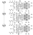
- FIG. 4 is an explanatory diagram showing the contents of a first fuel switching process in an embodiment according to the present disclosure.
- FIG. 11 is an explanatory diagram showing the content of a modified example of the first fuel switching process in an embodiment according to the present disclosure.
- FIG. 4 is an explanatory diagram showing the contents of a second fuel switching process in an embodiment according to the present disclosure.
- FIG. 11 is an explanatory diagram showing the content of a third fuel switching process in an embodiment according to the present disclosure.
- FIG. 11 is an explanatory diagram showing the content of a fourth fuel switching step in an embodiment according to the present disclosure.
- FIG. 4 is an explanatory diagram showing the contents of a fuel switching process in a first comparative example.
- FIG. 11 is an explanatory diagram showing the contents of a fuel switching process in a second comparative example.
- FIG. 2 is an explanatory diagram simply illustrating the contents of a first fuel switching process in an embodiment according to the present disclosure.
- the gas turbine facility in this embodiment includes a gas turbine 1 , a fuel supply system 30 capable of supplying fuel to the gas turbine 1 , and a control device 50 .
- the gas turbine 1 includes a compressor 10 capable of compressing air A to generate compressed air Acom, a combustor 20 capable of burning fuel in the compressed air Acom to generate combustion gas CG, and a turbine 15 capable of being driven by the combustion gas CG.
- the compressor 10 has a compressor rotor 11 that rotates around the rotor axis Ar, and a compressor casing 12 that covers the compressor rotor 11.
- the turbine 15 has a turbine rotor 16 that rotates around the rotor axis Ar, and a turbine casing 17 that covers the turbine rotor 16.
- the direction in which the rotor axis Ar extends is referred to as the rotor axial direction Da
- one of the two sides of this rotor axial direction Da is referred to as the axial upstream side Dau
- the other is referred to as the axial downstream side Dad.
- the compressor 10 is disposed on the axially upstream side Dau relative to the turbine 15.
- the compressor rotor 11 and the turbine rotor 16 are located on the same rotor axis Ar and are connected to each other to form the gas turbine rotor 2.
- the rotor of a generator GEN is connected to this gas turbine rotor 2.
- the gas turbine 1 further includes an intermediate casing 3 disposed between the compressor casing 12 and the turbine casing 17. Compressed air Acom from the compressor 10 flows into the intermediate casing 3. The combustor 20 is attached to the intermediate casing 3.
- the combustor 20 is connected to a fuel supply system 30.
- the combustor 20 can generate combustion gas CG by burning fuel from the fuel supply system 30 in compressed air Acom from the compressor 10.
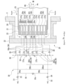
- the combustor 20 has an outer cylinder 21, an end cover 22, an inner cylinder 23, an air hole plate 24, a combustion cylinder 25, and a plurality of burner groups 26.
- the outer cylinder 21, the inner cylinder 23, and the combustion cylinder 25 are all cylindrical around the combustor axis Ac.
- the direction in which the combustor axis Ac extends is the combustor axial direction Dc
- one side of this combustor axial direction Dc is the base end side Dcb
- the other side of this combustor axial direction Dc is the tip side Dct.
- the tip end Dct of the outer cylinder 21 is connected to the intermediate casing 3.
- the base end Dcb of the outer cylinder 21 is blocked by the end cover 22.
- the inner cylinder 23 is arranged on the inner periphery of the outer cylinder 21 with a gap therebetween.
- the space between the inner periphery of the outer cylinder 21 and the outer periphery of the inner cylinder 23 forms a flow path for the compressed air Acom that flows into the intermediate casing 3.
- the air hole plate 24 is arranged on the inner periphery of the inner cylinder 23. This air hole plate 24 is also arranged on the end cover 22 with a gap in the combustor axial direction Dc.
- the space between the end cover 22 and the air hole plate 24 forms a flow path for the compressed air Acom.
- This flow path is connected to the flow path between the inner periphery of the outer cylinder 21 and the outer periphery of the inner cylinder 23.
- the air hole plate 24 is fixed to the end cover 22 via a support or the like.
- the inner cylinder 23 is fixed to the air hole plate 24.
- the air hole plate 24 has multiple air holes 24h that penetrate in the combustor axial direction Dc.
- the combustion cylinder 25 is fixed to the tip side Dct of the inner cylinder 23. The inner circumference of this combustion cylinder 25 forms a combustion space in which fuel is burned.
- the burner groups 26 include an inner burner group 26i and an outer burner group 26o.
- the inner burner group 26i is arranged on the combustor axis Ac.
- the outer burner groups 26o are arranged around the inner burner group 26i.
- Each of the burner groups 26 includes a first burner 27a and a plurality of second burners 27b.
- the second burners 27b are arranged around the first burner 27a.
- the first burner 27a and the second burners 27b each include an air flow path frame 28 through which air can flow and which can inject air into the combustion tube 25, and a nozzle 29 arranged in the air flow path frame 28 and which can inject fuel into the air flow path frame 28.
- the nozzle 29 of the first burner 27a is referred to as the first nozzle 29a
- the nozzle 29 of the second burner 27b is referred to as the second nozzle 29b
- the air flow path frame 28 of the first burner 27a is called the first air flow path frame 28a
- the air flow path frame 28 of the second burner 27b is called the second air flow path frame 28b.
- one burner group 26 is depicted as having one first burner 27a and six second burners 27b. However, in reality, one burner group 26 has several first burners 27a and several tens of second burners 27b. For this reason, the combustor 20 in this embodiment is called a multi-cluster combustor.
- each air flow path frame 28 of each burner 27 is formed by the inner circumferential surface of one of the multiple air holes 24h of the air hole plate 24 described above. Therefore, each air flow path frame 28 is formed by a part of the air hole plate 24.
- the compressed air Acom that flows into the intermediate casing 3 flows into the air flow path frame 28 for each of the multiple burners 27 via the flow path between the inner periphery of the outer cylinder 21 and the outer periphery of the inner cylinder 23, and the flow path between the end cover 22 and the air hole plate 24, as described above.
- the nozzles 29 for each of the multiple burners 27 inject fuel into the air flow path frame 28. Air and fuel are injected from the air flow path frame 28 for each of the multiple burners 27 into the combustion tube 25. The fuel injected into the combustion tube 25 is combusted in the air also injected into the combustion tube 25. The combustion gas formed by this combustion flows into the turbine 15.
- the fuel supply system 30 can supply the first fuel NG and the second fuel HG to the combustor 20.
- the first fuel NG is natural gas
- the second fuel HG is hydrogen gas.
- the fuel supply system 30 has a first fuel line 31, a second fuel line 32, a first fuel valve 33 provided in the first fuel line 31, a second fuel valve 34 provided in the second fuel line 32, a header line 36, a first gate valve 37a and a second gate valve 37b provided in the header line 36, a connecting line 35, a mixture ratio adjustment valve 35v provided in the connecting line 35, branch lines 38 branching off from the header line 36 for each of the multiple burners 27, and nozzle valves 39 provided in the branch lines 38 for each of the multiple burners 27.
- the first fuel line 31 is connected to a supply source of the first fuel NG and is a line through which the first fuel NG can flow.
- the second fuel line 32 is connected to a supply source of the second fuel HG and is a line through which the second fuel HG can flow.
- the first gate valve 37a provided in the header line 36 is capable of dividing the header line 36 into a first header section 36a and a second header section 36b.
- the second gate valve 37b provided in the header line 36 is capable of dividing the second header section 36b into a first side second header section 36bi on the first header section 36a side and a second side second header section 36bo which is the remaining part of the second header section 36b.
- the first fuel line 31 is connected to the first header section 36a in the header line 36.
- the second fuel line 32 is connected to the second side second header section 36bo in the header line 36.
- first branch lines 38a which are a portion of the branch lines 38 for each of the plurality of burners 27, branch out.
- Each of the plurality of first branch lines 38a is connected to a first nozzle 29a, which is a nozzle 29 for each of the plurality of first burners 27a.
- second header section 36b a plurality of second branch lines 38b, which are the branch lines 38 excluding the plurality of first branch lines 38a, branch out.
- Each of the plurality of second branch lines 38b is connected to a second nozzle 29b, which is a nozzle 29 for each of the plurality of second burners 27b.
- first side second header section 36bi which is a portion of the second header section 36b
- first side second branch lines 38bi which are a portion of the second branch lines 38b for each of the plurality of second branch lines 38b
- branch out Each of the plurality of first side second branch lines 38bi is connected to a plurality of first side second nozzles 29bi, which are a portion of the second nozzles 29b for each of the plurality of second nozzles 29b.
- second side second header portion 36bo which is a part of the second header portion 36b
- a plurality of second side second branch lines 38bo which are the second branch lines 38b excluding the plurality of first side second branch lines 38bi, branch out.
- Each of the plurality of second side second branch lines 38bo is connected to a plurality of second side second nozzles 29bo, which are the second nozzles 29b excluding the plurality of first side second nozzles 29bi, among the plurality of second nozzles 29b.
- the first side second nozzle 29bi is the second nozzle 29b of the inner burner group 26i of the multiple burner groups 26.
- the second side second nozzle 29bo is the second nozzle 29b of the outer burner group 26o of the multiple burner groups 26.
- the connecting line 35 connects the first fuel line 31 to a position between the position where the first fuel line 31 is connected to the header line 36 and the position where the first fuel valve 33 is provided, and the second fuel line 32 to a position between the position where the second fuel line 32 is connected to the header line 36 and the position where the second fuel valve 34 is provided.
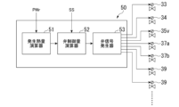
- the control device 50 has a heat generation amount calculator 51, a valve control amount calculator 52, and a valve signal generator 53.
- the required output PWr for the gas turbine 1 is input to the heat generation amount calculator 51 from the outside.
- the heat generation amount calculator 51 calculates the total heat generation amount generated by the combustion of the fuel supplied to the combustor 20 according to this required output PWr.
- the fuel switching command SS is input to the valve control amount calculator 52 from the outside, and the total heat generation amount is input to the valve control amount calculator 52.
- the valve control amount calculator 52 calculates the control amounts of the multiple valves described above according to the switching command SS and the total heat generation amount.
- the valve signal generator 53 receives the control amounts of the multiple valves from the valve control amount calculator 52.
- the valve signal generator 53 creates a valve signal for each valve according to the control amount for each of the multiple valves, and sends this valve signal to the corresponding valve.
- This control device 50 is capable of executing a fuel switching process for switching the fuel supplied to the combustor 20 from the first fuel NG to the second fuel HG.
- This control device 50 is capable of executing a first fuel switching process, a second fuel switching process, a third fuel switching process, and a fourth fuel switching process as fuel switching processes. Note that while these fuel switching processes are being executed, the gas turbine output does not change. In other words, while these fuel switching processes are being executed, the total amount of heat generated by the combustion of the fuel supplied to the combustor 20 does not change.
- This first fuel switching process is a process for switching the fuel from the first fuel NG to the second fuel HG when the gas turbine output is low.
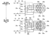
- This first fuel switching process includes a first fuel exclusive combustion process S1, a mixed combustion process S2, a second fuel exclusive combustion preparation process S3, and a second fuel exclusive combustion process S4. Note that for simplification, some of the first nozzles 29a and some of the second nozzles 29b are omitted in FIG. 5.
- the control device 50 opens the first fuel valve 33, closes the second fuel valve 34, closes the first gate valve 37a, opens the second gate valve 37b, and closes the mixture ratio adjustment valve 35v.
- the second fuel HG does not flow into the header line 36, and only the first fuel NG flows into the first header section 36a in the header line 36.
- the first fuel NG that flows into the first header section 36a flows into the first nozzles 29a via the first branch lines 38a branching off from the first header section 36a, and is sprayed from the first nozzles 29a.
- all of the nozzle valves 39 provided in the first branch lines 38a are open.
- the first fuel exclusive combustion step S1 only the first fuel NG is supplied to the first nozzles 29a, and neither the first fuel NG nor the second fuel HG is supplied to the second nozzles 29b. Therefore, in the first fuel exclusive combustion step S1, only the first fuel NG injected from the first nozzle 29a is combusted.
- the heat generation amount calculator 51 of the control device 50 calculates the total amount of heat generated by the combustion of the fuel supplied to the combustor 20 in order to realize this first fuel exclusive combustion process S1 and to reduce the gas turbine output.
- the valve control amount calculator 52 calculates the total flow rate of the first fuel NG corresponding to this total amount of heat generation. From this total flow rate of the first fuel NG, the valve control amount calculator 52 selects the nozzles 29 that supply the first fuel NG from among the multiple nozzles 29 and determines the flow rate of the first fuel NG to be supplied to each nozzle 29. Here, the valve control amount calculator 52 selects multiple first nozzles 29a from among the multiple nozzles 29.
- the valve control amount calculator 52 determines the open/closed states of the first fuel valve 33, the second fuel valve 34, the first gate valve 37a, the second gate valve 37b, and the mixture ratio adjustment valve 35v so that the first fuel NG is supplied only to the multiple first nozzles 29a, and determines the valve opening degree of each nozzle valve 39 provided in the multiple first branch lines 38a.
- the valve signal generator 53 creates valve signals for multiple valves according to the contents determined by the valve control amount calculator 52 for multiple valves, and sends each valve signal to the corresponding valve.
- the control device 50 executes the mixed combustion process S2.
- the control device 50 opens the first fuel valve 33, opens the second fuel valve 34, closes the first gate valve 37a, opens the second gate valve 37b, and closes the mixture ratio control valve 35v.
- the second fuel valve 34 among the multiple valves changes from a closed state to an open state.
- the first fuel NG continues to flow into the first header section 36a in the header line 36
- the second fuel HG flows into the second header section 36b in the header line 36.
- the first fuel NG that has flowed into the first header section 36a flows into the multiple first nozzles 29a via the multiple first branch lines 38a branching off from the first header section 36a, and is sprayed from the multiple first nozzles 29a.
- the second fuel HG that has flowed into the second header portion 36b flows into the second nozzles 29b via the second branch lines 38b that branch off from the second header portion 36b, and is ejected from the second nozzles 29b.
- the number of nozzles 29 that eject the second fuel HG is greater than the number of nozzles 29 that eject the first fuel NG.
- the total cross-sectional area of the air flow path frame 28 from which the second fuel HG is ejected is greater than the total cross-sectional area of the air flow path frame 28 from which the first fuel NG is ejected.
- the valve control amount calculator 52 of the control device 50 calculates the total flow rate of the first fuel NG and the total flow rate of the second fuel HG corresponding to the total heat generation amount previously calculated by the heat generation amount calculator 51. Because the total heat generation amount in the first fuel exclusive combustion process S1 and the total heat generation amount in the mixed combustion process S2 are the same, the total flow rate of the first fuel NG in the mixed combustion process S2 in which the second fuel HG is supplied to the combustor 20 is less than the total flow rate of the first fuel NG in the first fuel exclusive combustion process S1 in which the second fuel HG is not supplied to the combustor 20.
- the valve control amount calculator 52 selects, from the total flow rate of the first fuel NG, a nozzle 29 that supplies the first fuel NG from among the multiple nozzles 29, and determines the flow rate of the first fuel NG to be supplied to each nozzle 29. Furthermore, the valve control amount calculator 52 selects, from the total flow rate of the second fuel HG, a nozzle 29 that supplies the second fuel HG from among the multiple nozzles 29, and determines the flow rate of the second fuel HG to be supplied to each nozzle 29. Here, the valve control amount calculator 52 selects a plurality of first nozzles 29a as nozzles 29 that supply the first fuel NG from among the plurality of nozzles 29.
- the valve control amount calculator 52 also selects a plurality of second nozzles 29b as nozzles 29 that supply the second fuel HG from among the plurality of nozzles 29.
- the valve control amount calculator 52 determines the open/close states of the first fuel valve 33, the second fuel valve 34, the first gate valve 37a, the second gate valve 37b, and the mixture ratio adjustment valve 35v so that the first fuel NG is supplied only to the plurality of first nozzles 29a, and the second fuel HG is supplied only to the plurality of second nozzles 29b.
- the valve control amount calculator 52 determines the valve opening degree of each nozzle valve 39 provided in the plurality of first branch lines 38a, and the valve opening degree of each nozzle 29 provided in the plurality of second branch lines 38b.
- the control device 50 executes the second fuel exclusive combustion preparation process S3.
- the control device 50 closes the first fuel valve 33, opens the second fuel valve 34, closes the first gate valve 37a, opens the second gate valve 37b, and closes the mixture ratio control valve 35v.
- the first fuel valve 33 among the multiple valves changes from an open state to a closed state.
- the second fuel HG continues to flow into the second header section 36b in the header line 36, while the first fuel NG no longer flows into the header line 36.
- the second fuel HG that has flowed into the second header section 36b flows into the multiple second nozzles 29b through the multiple second branch lines 38b branching off from the second header section 36b, as in the mixed combustion process S2, and is sprayed from the multiple second nozzles 29b.
- this second fuel exclusive combustion preparation process S3 the first fuel NG and the second fuel HG are not supplied to the first nozzles 29a, and only the second fuel HG is supplied to the second nozzles 29b. Therefore, in this second fuel exclusive combustion preparation process S3, only the second fuel HG sprayed from the second nozzles 29b is combusted.
- the valve control amount calculator 52 of the control device 50 calculates the total flow rate of the second fuel HG corresponding to the total heat generation amount previously calculated by the heat generation amount calculator 51. Because the total heat generation amount in the mixed combustion process S2 and the total heat generation amount in the second fuel exclusive combustion preparation process S3 are the same, the total flow rate of the second fuel HG in the second fuel exclusive combustion preparation process S3, in which only the second fuel HG is supplied to the combustor 20, is greater than the total flow rate of the second fuel HG in the mixed combustion process S2, in which the first fuel NG and the second fuel HG are supplied to the combustor 20.
- the valve control amount calculator 52 selects, from the multiple nozzles 29, the nozzles 29 that supply the second fuel HG, based on the total flow rate of the second fuel HG, and determines the flow rate of the second fuel HG to be supplied to each nozzle 29.
- the valve control amount calculator 52 selects, from the multiple nozzles 29, the multiple second nozzles 29b as the nozzles 29 that supply the second fuel HG.
- the valve control amount calculator 52 determines the open/close states of the first fuel valve 33, the second fuel valve 34, the first gate valve 37a, the second gate valve 37b, and the mixture ratio control valve 35v so that the second fuel HG is supplied only to the second nozzles 29b. Furthermore, the valve control amount calculator 52 determines the valve opening degree of each nozzle 29 provided in the second branch lines 38b.
- the control device 50 executes the second fuel exclusive combustion process S4.
- the control device 50 closes the first fuel valve 33, opens the second fuel valve 34, opens the first gate valve 37a, opens the second gate valve 37b, and closes the mixture ratio adjustment valve 35v. Therefore, in the process from the second fuel exclusive combustion preparation process S3 to the second fuel exclusive combustion process S4, among the multiple valves, the first gate valve 37a changes from a closed state to an open state. As a result, only the second fuel HG flows into the entire header line 36.
- the second fuel HG that has flowed into the header line 36 flows into the second nozzles 29b through the second branch lines 38b branching from the second header portion 36b in the header line 36, and is ejected from the second nozzles 29b.
- the second fuel HG also flows into the first nozzles 29a through the first branch lines 38a branching from the first header portion 36a in the header line 36, and is ejected from the first nozzles 29a.
- the second fuel HG is not supplied to the first nozzles 29a of the inner burner group 26i among the first nozzles 29a.
- the nozzle valves 39 of the first branch lines 38a connected to the first nozzles 29a of the inner burner group 26i among the nozzle valves 39 provided in the first branch lines 38a are in a closed state.
- the second fuel HG should not be supplied to the first nozzles 29a of the inner burner group 26i due to restrictions on the total flow rate of the second fuel HG supplied to the combustor 20, etc. Therefore, in this second fuel mono-combustion step S4, depending on the total flow rate of the second fuel HG supplied to the combustor 20, as shown in FIG. 6, all of the nozzle valves 39 provided in the multiple first branch lines 38a may be opened to supply the second fuel HG to all of the first nozzles 29a.
- this second fuel exclusive combustion process S4 only the second fuel HG is supplied to all of the nozzles 29 except for the first nozzle 29a of the inner burner group 26i out of the multiple nozzles 29. Therefore, in this second fuel exclusive combustion process S4, only the second fuel HG ejected from the second nozzle 29b and the second fuel HG ejected from some of the first fuel NG are combusted.
- the total flow rate of the second fuel HG in the second fuel exclusive combustion step S4 is the same as the total flow rate of the second fuel HG in the second fuel exclusive combustion preparation step S3.
- the valve control amount calculator 52 selects the nozzles 29 that supply the second fuel HG from among the multiple nozzles 29 based on the total flow rate of the second fuel HG, and determines the flow rate of the second fuel HG to be supplied to each nozzle 29.
- the valve control amount calculator 52 selects the multiple second nozzles 29b and some of the multiple first nozzles 29a as the nozzles 29 that supply the second fuel HG from among the multiple nozzles 29.
- the valve control amount calculator 52 determines the open/close states of the first fuel valve 33, the second fuel valve 34, the first gate valve 37a, the second gate valve 37b, and the mixture ratio adjustment valve 35v so that the second fuel HG is supplied only to the multiple second nozzles 29b and some of the multiple first nozzles 29a. Furthermore, the valve control amount calculator 52 determines the valve opening degree of each nozzle 29 provided in the multiple branch lines 38.
- the fuel supply system 30x in the first comparative example has a first fuel line 31x through which the first fuel NG can flow, a second fuel line 32x through which the second fuel HG can flow, an integrated line 36x through which the first fuel NG and the second fuel HG can flow, and branch lines 38 that branch off from the integrated line 36x and branch off for each of the nozzles 29.
- the first fuel line 31x and the second fuel line 32x are both connected to one end of the integrated line 36x.
- the first fuel line 31x is provided with a first fuel valve 33
- the second fuel line 32x is provided with a second fuel valve 34.
- the branch lines 38 that branch off for each of the nozzles 29 are provided with nozzle valves 39.
- a part of the branch lines 38 that branch off for each of the nozzles 29 constitutes a first branch line 38a that is connected to the first nozzle 29a, and the other branch lines 38 constitute a second branch line 38b that is connected to the second nozzle 29b.
- the fuel supply system 30x in the first comparative example when the first fuel valve 33 and the second fuel valve 34 are opened, the first fuel NG that has passed through the first fuel valve 33 and the second fuel HG that has passed through the second fuel valve 34 will always mix in the integrated line 36x. For this reason, in the fuel supply system 30x in the first comparative example, when the first fuel valve 33 and the second fuel valve 34 are opened, only the first fuel NG is supplied to some of the multiple nozzles 29, and it is not possible to supply only the second fuel HG to the remaining nozzles 29.
- the fuel switching process in the first comparative example includes a first fuel exclusive combustion process S1x, a mixed fuel combustion preparation process S2x, a mixed fuel mixed combustion process S3x, and a second fuel exclusive combustion process S4x. Note that even during the fuel switching process in this first comparative example, the gas turbine output does not change. In other words, during the execution of these fuel switching processes, the total amount of heat generated by the combustion of the fuel supplied to the combustor does not change.
- the first fuel valve 33 is opened, the second fuel valve 34 is closed, the nozzle valve 39 of the first branch line 38a is opened, and the nozzle valve 39 of the second branch line 38b is closed.
- the second fuel HG does not flow into the integrated line 36x, and only the first fuel NG flows into the integrated line 36x.
- the first fuel NG that flows into the integrated line 36x flows only into the first nozzle 29a via the first branch line 38a.
- this first fuel exclusive combustion process S1 only the first fuel NG is supplied to the first nozzle 29a, and the first fuel NG and the second fuel HG are not supplied to the second nozzles 29b. Therefore, in this first fuel exclusive combustion process S1x, only the first fuel NG sprayed from the first nozzle 29a is combusted, similar to the first fuel exclusive combustion process S1 of the first fuel switching process in this embodiment.
- the first fuel valve 33 is open, the second fuel valve 34 is closed, the nozzle valve 39 of the first branch line 38a is open, and the nozzle valve 39 of the second branch line 38b is open. Therefore, in the process from the first fuel exclusive combustion process S1x to the mixed combustion preparation process S2x, the nozzle valve 39 of the second branch line 38b changes from a closed state to an open state. As a result, the first fuel NG that flows into the integrated line 36x flows into the first nozzle 29a via the first branch line 38a, and also flows into the second nozzle 29b via the second branch line 38b.
- the first fuel valve 33 is open, the second fuel valve 34 is open, the nozzle valve 39 of the first branch line 38a is open, and the nozzle valve 39 of the second branch line 38b is open. Therefore, in the process from the mixed fuel combustion preparation process S2x to the mixed fuel combustion process S3x, the second fuel valve 34 changes from a closed state to an open state. As a result, the first fuel NG and the second fuel HG flow into the integrated line 36x. The first fuel NG and the second fuel HG that flow into the integrated line 36x are mixed here to become a mixed fuel.
- the mixed fuel in the integrated line 36x flows into the first nozzle 29a via the first branch line 38a, and also flows into the second nozzle 29b via the second branch line 38b.
- the mixed fuel is supplied to the first nozzle 29a and the multiple second nozzles 29b. Therefore, in this mixed fuel combustion process S3x, the mixed fuel sprayed from the first nozzle 29a and the multiple second nozzles 29b is combusted.
- the first fuel valve 33 In the second fuel exclusive combustion process S4x, the first fuel valve 33 is closed, the second fuel valve 34 is open, the nozzle valve 39 of the first branch line 38a is open, and the nozzle valve 39 of the second branch line 38b is open. Therefore, in the process from the mixed fuel combustion process S3x to the second fuel exclusive combustion process S4x, the first fuel valve 33 changes from an open state to a closed state. As a result, only the second fuel HG flows into the integrated line 36x, and the first fuel NG does not flow in. The second fuel HG that flows into the integrated line 36x flows into the first nozzle 29a via the first branch line 38a, and also flows into the second nozzle 29b via the second branch line 38b.
- this second fuel exclusive combustion process S4x only the second fuel HG is supplied to the first nozzle 29a and the multiple second nozzles 29b. Therefore, in this second fuel exclusive combustion process S4x, similar to the second fuel exclusive combustion process S4 of the first fuel switching process in this embodiment, only the second fuel HG sprayed from the first nozzle 29a and the multiple second nozzles 29b is combusted.
- natural gas which is the first fuel NG
- hydrogen gas which is the second fuel HG
- hydrogen gas which is the second fuel HG
- hydrogen gas has a characteristic that the possibility of backfiring is much higher when the fuel-air ratio is high, compared to natural gas, which is the first fuel NG.
- hydrogen gas does not deteriorate in combustibility even when the fuel-air ratio is low, compared to natural gas.
- natural gas does not have a high possibility of backfiring, compared to hydrogen gas, even when the fuel-air ratio is high.
- natural gas has the characteristic of having poor combustibility when the fuel-air ratio is low, but also has the characteristic of not increasing the possibility of flashback even when the fuel-air ratio is high.
- hydrogen gas has the characteristic of not decreasing its combustibility much even when the fuel-air ratio is low, but has the characteristic of greatly increasing the possibility of flashback when the fuel-air ratio is high.
- the first fuel NG is injected from only the first nozzle 29a, and neither the first fuel NG nor the second fuel HG is injected from the second nozzle 29b.
- the mixed combustion preparation process S2x the first fuel NG is injected from the first nozzle 29a and the multiple second nozzles 29b. That is, in both the first fuel exclusive combustion process S1 and the mixed combustion preparation process S2x, only the first fuel NG is injected.
- the flow rate of the first fuel NG supplied to the combustor in the mixed combustion preparation process S2x is the same as the flow rate of the first fuel NG supplied to the combustor in the first fuel exclusive combustion process S1x.
- the number of nozzles 29 that inject the first fuel NG in the mixed combustion preparation process S2x is greater than the number of nozzles 29 that inject the first fuel NG in the first fuel exclusive combustion process S1x.
- the fuel-air ratio for the first fuel NG in the mixed combustion preparation process S2x is lower than the fuel-air ratio for the first fuel NG in the first fuel exclusive combustion process S1x.
- natural gas which is the first fuel NG, has a characteristic of having poor combustibility when the fuel-air ratio is low. Therefore, the combustibility of the fuel is poor in the mixed combustion preparation process S2x.
- the combustibility of the fuel temporarily deteriorates during the process of switching from the first fuel NG to the second fuel HG.
- the fuel supply system 30z in the second comparative example has a first fuel line 31z through which the first fuel NG can flow, a second fuel line 32z through which the second fuel HG can flow, and second branch lines 38b branching off from the second fuel line 32z for each of the second nozzles 29b.
- the first fuel line 31z is connected to the first nozzle 29a.
- the first fuel line 31z is provided with a first fuel valve 33 and a nozzle valve 39 for the first nozzle 29a.
- the second fuel line 32z is completely independent from the first fuel line 31z.
- the second fuel line 32z is provided with a second fuel valve 34.
- the second branch lines 38b for each of the second nozzles 29b are provided with nozzle valves 39.
- the second fuel line 32z is completely independent of the first fuel line 31z, so even if the first fuel valve 33 and the second fuel valve 34 are open, the first fuel NG and the second fuel HG do not mix. Also, in the fuel supply system 30z in the second comparative example, the first fuel NG can only flow into the first nozzle 29a, and the second fuel HG can only flow into the second nozzle 29b.
- the fuel switching process in the second comparative example includes a first fuel exclusive combustion process S1z, a mixed combustion process S2z, and a second fuel exclusive combustion process S4z.
- the first fuel valve 33 is open, the nozzle valve 39 for the first nozzle 29a is open, the second fuel valve 34 is closed, and the nozzle valve 39 of the second branch line 38b is closed.
- the first fuel NG is supplied to the first nozzle 29a, and neither the first fuel NG nor the second fuel HG is supplied to the second nozzle 29b. Therefore, in this first fuel exclusive combustion process S1z, only the first fuel NG sprayed from the first nozzle 29a is combusted.
- the first fuel valve 33 is open, the nozzle valve 39 for the first nozzle 29a is open, the second fuel valve 34 is open, and the nozzle valve 39 of the second branch line 38b is open. Therefore, in the process from the first fuel exclusive combustion process S1z to the mixed combustion process S2z, the second fuel valve 34 changes from a closed state to an open state, and the nozzle valve 39 of the second branch line 38b changes from a closed state to an open state.
- the first fuel NG is supplied only to the first nozzle 29a
- the second fuel HG is supplied only to the multiple second nozzles 29b. Therefore, in this mixed combustion process S2z, the first fuel NG sprayed from the first nozzle 29a is combusted, and the second fuel HG sprayed from the multiple second nozzles 29b is combusted.
- the first fuel valve 33 In the second fuel exclusive combustion step S3z, the first fuel valve 33 is closed, the nozzle valve 39 for the first nozzle 29a is closed, the second fuel valve 34 is open, and the nozzle valve 39 of the second branch line 38b is open. Therefore, in the process of going from the mixed combustion step S2z to the second fuel exclusive combustion step S3z, the first fuel valve 33 changes from an open state to a closed state, and the nozzle valve 39 for the first nozzle 29a changes from an open state to a closed state. As a result, only the second fuel HG is supplied to the second nozzle 29b, and neither the first fuel NG nor the second fuel HG is supplied to the first nozzle 29a.
- the first fuel NG cannot be supplied to the second nozzle 29b, so the first fuel NG is supplied only to the first nozzle 29a, and the first fuel exclusive combustion step S1z is executed. Therefore, in the second comparative example, even if an attempt is made to increase the gas turbine output only by the exclusive combustion of the first fuel NG, the gas turbine output corresponding to the total number of the nozzles 29 cannot be obtained. Also, in the second comparative example, the second fuel HG cannot be supplied to the first nozzle 29a, so the second fuel HG is supplied only to the second nozzle 29b, and the second fuel exclusive combustion step S3z is executed.
- the gas turbine output corresponding to the total number of the nozzles 29 cannot be obtained.
- the gas turbine output corresponding to the total number of the nozzles 29 cannot be obtained.
- the first fuel exclusive combustion process S1 the first fuel valve 33 is opened, the second fuel valve 34 is closed, and the first gate valve 37a is closed.
- the second fuel HG does not flow into the header line 36, and only the first fuel NG flows into the first header section 36a in the header line 36.
- the first fuel NG that flows into the first header section 36a flows into the first nozzles 29a via the first branch lines 38a branching off from the first header section 36a, and is ejected from the first nozzles 29a.
- this first fuel exclusive combustion process S1 only the first fuel NG is supplied to the first nozzles 29a, and the first fuel NG and the second fuel HG are not supplied to the second nozzles 29b. Therefore, in this first fuel exclusive combustion process S1, only the first fuel NG ejected from the first nozzles 29a is combusted.
- the first fuel valve 33 is opened, the second fuel valve 34 is opened, and the first gate valve 37a is closed.
- the first fuel NG continues to flow into the first header section 36a in the header line 36, while the second fuel HG flows into the second header section 36b in the header line 36.
- the first fuel NG that flows into the first header section 36a flows into the first nozzles 29a through the first branch lines 38a branching off from the first header section 36a, and is sprayed from the first nozzles 29a.
- the second fuel HG that flows into the second header section 36b flows into the second nozzles 29b through the second branch lines 38b branching off from the second header section 36b, and is sprayed from the second nozzles 29b.
- the mixed combustion process S2 only the first fuel NG is supplied to the first nozzles 29a, and only the second fuel HG is supplied to the second nozzles 29b. Therefore, in the mixed combustion step S2, the first fuel NG ejected from the first nozzle 29a is combusted, and the second fuel HG ejected from the second nozzle 29b is combusted. At this time, as described above, the number of nozzles 29 ejecting the second fuel HG is greater than the number of nozzles 29 ejecting the first fuel NG. In other words, the total cross-sectional area of the air flow path frame 28 from which the second fuel HG is ejected is greater than the total cross-sectional area of the air flow path frame 28 from which the first fuel NG is ejected.
- the total heat generation amount in the first fuel exclusive combustion process S1 and the total heat generation amount in the mixed combustion process S2 are the same, the total flow rate of the first fuel NG in the mixed combustion process S2 in which the second fuel HG is supplied to the combustor 20 is smaller than the total flow rate of the first fuel NG in the first fuel exclusive combustion process S1 in which the second fuel HG is not supplied to the combustor 20. Therefore, the fuel-air ratio for the first fuel NG in the mixed combustion process S2 is lower than the fuel-air ratio for the first fuel NG in the first fuel exclusive combustion process S1.
- natural gas which is the first fuel NG, has a characteristic that it has poor combustibility when the fuel-air ratio is low.
- the first fuel valve 33 is closed, the second fuel valve 34 is open, and the first gate valve 37a is closed.
- the second fuel HG continues to flow into the second header section 36b in the header line 36, while the first fuel NG stops flowing into the header line 36.
- the second fuel HG that has flowed into the second header section 36b flows into the multiple second nozzles 29b via the multiple second branch lines 38b branching off from the second header section 36b, as in the mixed combustion step S2, and is sprayed from the multiple second nozzles 29b. Therefore, in this second fuel exclusive combustion preparation step S3, only the second fuel HG sprayed from the second nozzles 29b is combusted.
- the first fuel valve 33 is closed, the second fuel valve 34 is open, and the first gate valve 37a is open.
- the second fuel HG flows into the entire header line 36.
- the second fuel HG that flows into the header line 36 flows into the second nozzles 29b through the second branch lines 38b branching off from the second header section 36b in the header line 36, and is sprayed from the second nozzles 29b.
- the second fuel HG also flows into the first nozzles 29a through the first branch lines 38a branching off from the first header section 36a in the header line 36, and is sprayed from the first nozzles 29a. Therefore, in this second fuel exclusive combustion step S4, only the second fuel HG sprayed from the second nozzle 29b and the first nozzles 29a is combusted.
- the second fuel HG even if the fuel-air ratio for the first fuel NG, which is natural gas, becomes low during the fuel switching process, the second fuel HG also burns while the first fuel NG is burning, so the combustibility of the first fuel NG, which is natural gas, is compensated for, and deterioration of the fuel's combustibility can be suppressed.
- this second fuel switching process is a process of switching the fuel from the first fuel NG to the second fuel HG when the gas turbine output is low.
- the gas turbine output during this second fuel switching process is slightly higher than the gas turbine output during the first fuel switching process.
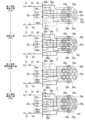
- this second fuel switching process also includes a first fuel exclusive combustion process S1a, a multi-fuel combustion process S2a, a second fuel exclusive combustion preparation process S3a, and a second fuel exclusive combustion process S4a. Note that, for the sake of simplification, some of the first nozzles 29a and some of the second nozzles 29b are also omitted in Fig. 7.
- the first fuel valve 33 is open, the second fuel valve 34 is closed, the first gate valve 37a is open, the second gate valve 37b is closed, and the mixture ratio control valve 35v is closed.
- the first gate valve 37a is closed and the second gate valve 37b is open, but in this first fuel exclusive combustion step S1a, the first gate valve 37a is open and the second gate valve 37b is closed.
- the second fuel HG does not flow into the header line 36, and only the first fuel NG flows into the first header section 36a and the first side second header section 36bi in the header line 36.
- the first fuel NG that flows into the first header section 36a flows into the multiple first nozzles 29a via the multiple first branch lines 38a branching off from the first header section 36a, and is sprayed from the multiple first nozzles 29a.
- the first fuel NG that flows into the first-side second header section 36bi flows into the first-side second nozzles 29bi, which are the second nozzles 29b of the inner burner group 26i, among the second nozzles 29b, via multiple first-side second branch lines 38bi that branch off from the first-side second header section 36bi.
- this first fuel exclusive combustion process S1a only the first fuel NG is supplied to the multiple first nozzles 29a and the first side second nozzles 29bi, and the first fuel NG and the second fuel HG are not supplied to the multiple second side second nozzles 29bo. Therefore, in this first fuel exclusive combustion process S1a, only the first fuel NG sprayed from the first nozzles 29a and the first side second nozzles 29bi is combusted.
- the first fuel valve 33 is opened, the second fuel valve 34 is opened, the first gate valve 37a is closed, the second gate valve 37b is open, and the mixture ratio control valve 35v is closed.
- the first fuel NG continues to flow into the first header section 36a in the header line 36, and the second fuel HG flows into the second header section 36b in the header line 36.
- the first fuel NG that flows into the first header section 36a flows into the first nozzles 29a through the first branch lines 38a branching off from the first header section 36a, and is sprayed from the first nozzles 29a.
- the second fuel HG that flows into the second header section 36b flows into the second nozzles 29b through the second branch lines 38b branching off from the second header section 36b, and is sprayed from the second nozzles 29b.
- the number of nozzles 29 that eject the second fuel HG is greater than the number of nozzles 29 that eject the first fuel NG.
- the total cross-sectional area of the air flow path frame 28 from which the second fuel HG is ejected is greater than the total cross-sectional area of the air flow path frame 28 from which the first fuel NG is ejected.
- the first fuel valve 33 is closed, the second fuel valve 34 is open, the first gate valve 37a is closed, the second gate valve 37b is open, and the mixture ratio control valve 35v is closed.
- the second fuel HG continues to flow into the second header section 36b in the header line 36, while the first fuel NG no longer flows into the header line 36.
- the second fuel HG that has flowed into the second header section 36b flows into the multiple second nozzles 29b via the multiple second branch lines 38b branching off from the second header section 36b, similar to the mixed combustion step S2a, and is sprayed from the multiple second nozzles 29b.
- this second fuel exclusive combustion preparation process S3a the first fuel NG and the second fuel HG are not supplied to the first nozzles 29a, and only the second fuel HG is supplied to the second nozzles 29b. Therefore, in this second fuel exclusive combustion preparation process S3a, only the second fuel HG sprayed from the second nozzles 29b is combusted.
- the first fuel valve 33 is closed, the second fuel valve 34 is open, the first gate valve 37a is open, the second gate valve 37b is open, and the mixture ratio adjustment valve 35v is closed.
- the second fuel HG flows into the entire header line 36.
- the second fuel HG that flows into the header line 36 flows into the multiple second nozzles 29b via the multiple second branch lines 38b branching off from the second header section 36b in the header line 36 and is sprayed from the multiple second nozzles 29b, and also flows into the multiple first nozzles 29a via the multiple first branch lines 38a branching off from the first header section 36a in the header line 36 and is sprayed from the multiple first nozzles 29a.
- the second fuel HG is not supplied to the first nozzles 29a of the inner burner group 26i among the multiple first nozzles 29a, depending on the total flow rate of the second fuel HG supplied to the combustor 20, as described with reference to FIG. 6, all of the nozzle valves 39 provided in the multiple first branch lines 38a may be opened to supply the second fuel HG to all of the first nozzles 29a.
- this second fuel exclusive combustion process S4a only the second fuel HG is supplied to all of the nozzles 29, except for the first nozzles 29a of the inner burner group 26i. Therefore, in this second fuel exclusive combustion process S4a, only the second fuel HG ejected from the second nozzles 29b and the second fuel HG ejected from some of the first nozzles 29a are combusted.
- the fuel-air ratio for the first fuel NG in the mixed combustion step S2a of the second fuel switching step is also lower than the fuel-air ratio for the first fuel NG in the first fuel exclusive combustion step S1a, just like the fuel-air ratio for the first fuel NG in the mixed combustion step S2 of the first fuel switching step.
- hydrogen gas which is the second fuel HG ejected from the second nozzle 29b, is also burning. Therefore, the combustion of hydrogen gas, which is the second fuel HG ejected from the second nozzle 29b, compensates for the combustibility of natural gas, which is the first fuel NG, and deterioration of the combustibility of the fuel can be suppressed.
- the fuel supply system 30 of this embodiment has a first gate valve 37a and a second gate valve 37b as valves that separate the header line 36, so that the position at which the header line 36 is separated into two can be changed. Therefore, the number of nozzles 29 that spray the first fuel NG in the first fuel exclusive combustion step S1a of the second fuel switching step can be changed to the number of nozzles 29 that spray the first fuel NG in the first fuel exclusive combustion step S1 of the first fuel switching step. Therefore, in this embodiment, it is possible to flexibly respond to output changes in the low output range when the first fuel NG is exclusively burned.
- this third fuel switching process is a process of switching the fuel from the first fuel NG to the second fuel HG when the gas turbine output is low.
- this third fuel switching process also includes a first fuel exclusive combustion process S1b, a mixed combustion process S2b, a second fuel exclusive combustion preparation process S3b, and a second fuel exclusive combustion process S4b. Note that, for simplification, some of the first nozzles 29a and some of the second nozzles 29b are also omitted in Fig. 8.
- the first fuel valve 33 is open, the second fuel valve 34 is closed, the first gate valve 37a is open, the second gate valve 37b is closed, and the mixture ratio adjustment valve 35v is closed.
- the second fuel HG does not flow into the header line 36, and only the first fuel NG flows into the first header section 36a and the first-side second header section 36bi in the header line 36.
- the first fuel NG that has flowed into the first header section 36a flows into the multiple first nozzles 29a via the multiple first branch lines 38a branching off from the first header section 36a, and is sprayed from the multiple first nozzles 29a.
- the first fuel NG that has flowed into the first-side second header section 36bi flows into the first-side second nozzle 29bi, which is the second nozzle 29b of the inner burner group 26i, among the second nozzles 29b, through a plurality of first-side second branch lines 38bi that branch off from the first-side second header section 36bi. Therefore, in this first fuel exclusive combustion process S1b, only the first fuel NG ejected from the first nozzle 29a and the first-side second nozzle 29bi is combusted.
- the first fuel valve 33 is open, the second fuel valve 34 is open, the first gate valve 37a is open, the second gate valve 37b is closed, and the mixture ratio control valve 35v is closed.
- the first gate valve 37a is closed and the second gate valve 37b is open, but in this mixed combustion process S2b, the first gate valve 37a is open and the second gate valve 37b is closed.
- the first fuel NG continues to flow into the first header section 36a and the first side second header section 36bi in the header line 36.
- the first fuel NG that has flowed into the first header section 36a flows into the multiple first nozzles 29a via the multiple first branch lines 38a branching off from the first header section 36a, and is sprayed from the multiple first nozzles 29a.
- the first fuel NG that has flowed into the first-side second header section 36bi flows into the first-side second nozzle 29bi, which is the second nozzle 29b of the inner burner group 26i, among the second nozzles 29b, through a plurality of first-side second branch lines 38bi branching from the first-side second header section 36bi.
- the second fuel HG flows into the second-side second header section 36bo in the header line 36.
- the second fuel HG that has flowed into the second-side second header section 36bo flows into the second-side second nozzle 29bo, which is the second nozzle 29b of the outer burner group 26o, among the second nozzles 29b, through a plurality of second-side second branch lines 38bo branching from the second-side second header section 36bo.
- the first fuel NG injected from the plurality of first nozzles 29a and the first-side second nozzle 29bi is combusted
- the second fuel HG injected from the plurality of second-side second nozzles 29bo is combusted.
- the number of nozzles 29 that eject the second fuel HG is greater than the number of nozzles 29 that eject the first fuel NG.
- the total cross-sectional area of the air flow path frame 28 from which the second fuel HG is ejected is greater than the total cross-sectional area of the air flow path frame 28 from which the first fuel NG is ejected.
- the first fuel valve 33 is closed, the second fuel valve 34 is open, the first gate valve 37a is closed, the second gate valve 37b is open, and the mixture ratio control valve 35v is closed.
- the second fuel HG flows into the entire second header section 36b in the header line 36, and the first fuel NG does not flow into the header line 36.
- the second fuel HG that has flowed into the second header section 36b flows into the second nozzles 29b via the second branch lines 38b branching off from the second header section 36b, and is sprayed from the second nozzles 29b.
- this second fuel exclusive combustion preparation step S3b the first fuel NG and the second fuel HG are not supplied to the first nozzles 29a, and only the second fuel HG is supplied to the second nozzles 29b. Therefore, in this second fuel exclusive combustion preparation process S3b, only the second fuel HG ejected from the second nozzle 29b is combusted.
- the first fuel valve 33 is closed, the second fuel valve 34 is open, the first gate valve 37a is open, the second gate valve 37b is open, and the mixture ratio control valve 35v is closed.
- the second fuel HG flows into the entire header line 36.
- the second fuel HG that flows into the header line 36 flows into the multiple second nozzles 29b via the multiple second branch lines 38b branching off from the second header section 36b in the header line 36 and is sprayed from the multiple second nozzles 29b, and also flows into the multiple first nozzles 29a via the multiple first branch lines 38a branching off from the first header section 36a in the header line 36 and is sprayed from the multiple first nozzles 29a.
- this second fuel exclusive combustion step S4b similarly to the second fuel exclusive combustion step S4 of the first fuel switching step and the second fuel exclusive combustion step S4a of the second fuel switching step, the second fuel HG is not supplied to the first nozzles 29a of the inner burner group 26i among the multiple first nozzles 29a due to the relationship with the total flow rate of the second fuel HG supplied to the combustor 20.
- this second fuel exclusive combustion step S4b only the second fuel HG ejected from the second nozzles 29b and the second fuel HG ejected from some of the first nozzles 29a are combusted.
- all of the nozzle valves 39 provided in the multiple first branch lines 38a may be opened to supply the second fuel HG to all of the first nozzles 29a.
- the fuel-air ratio for the first fuel NG in the mixed combustion step S2b of the third fuel switching step is also lower than the fuel-air ratio for the first fuel NG in the first fuel exclusive combustion step S1b, similar to the fuel-air ratios for the first fuel NG in the mixed combustion step S2 of the first fuel switching step and the mixed combustion step S2a of the second fuel switching step.
- this mixed combustion step S2b while natural gas as the first fuel NG ejected from the first nozzle 29a is being burned, hydrogen gas as the second fuel HG ejected from the second nozzle 29b is also burned. Therefore, the combustion of hydrogen gas as the second fuel HG ejected from the second nozzle 29b compensates for the combustibility of natural gas as the first fuel NG, and deterioration of the combustibility of the fuel can be suppressed.
- the fuel supply system 30 of this embodiment has a first gate valve 37a and a second gate valve 37b as valves that separate the header line 36, so that the position at which the header line 36 is separated into two can be changed. Therefore, the number of nozzles 29 that spray the first fuel NG in the mixed combustion process S2b of the third fuel switching process can be changed relative to the number of nozzles 29 that spray the first fuel NG in the mixed combustion process S2b of the second fuel switching process. Therefore, in this embodiment, the amount of effect of the combustion of the second fuel HG on the combustibility of the first fuel NG can be changed in the mixed combustion process S2b.
- This fourth fuel switching process is a process of switching the fuel from the first fuel NG to the second fuel HG when the gas turbine output is high.
- This fourth fuel switching process includes a first fuel exclusive combustion process S1c, a mixed fuel combustion process S2c, and a second fuel exclusive combustion process S4c.
- FIG. 9 also omits some of the first nozzles 29a and some of the second nozzles 29b.
- the high output here is, for example, 50% or more of the rated output of the gas turbine. However, this percentage changes depending on the gas turbine. In other words, in a certain gas turbine, the high output may be, for example, 75% or more of the rated output of the gas turbine.
- the first fuel valve 33 is opened, the second fuel valve 34 is closed, the first gate valve 37a is opened, the second gate valve 37b is opened, and the mixture ratio adjustment valve 35v is closed.
- the second fuel HG does not flow into the header line 36, and only the first fuel NG flows into the header line 36.
- the first fuel NG that flows into the first header section 36a in the header line 36 flows into the first nozzles 29a via the first branch lines 38a branching off from the first header section 36a, and is sprayed from the first nozzles 29a.
- the first fuel NG that flows into the second header section 36b in the header line 36 flows into the second nozzles 29b via the second branch lines 38b branching off from the second header section 36b.
- the first fuel valve 33 is opened, the second fuel valve 34 is closed, the first gate valve 37a is opened, the second gate valve 37b is opened, and the mixture ratio control valve 35v is opened. If the supply pressure of the second fuel HG from the second fuel supply source is higher than the supply pressure of the first fuel NG from the first fuel supply source, the second fuel HG flows from the second fuel line 32 through the connection line 35 and the mixture ratio control valve 35v into the first fuel line 31, where it is mixed with the first fuel NG to become a mixed fuel. This mixed fuel flows into the header line 36.
- the mixed fuel that flows into the first header section 36a in the header line 36 flows into the first nozzles 29a via the first branch lines 38a branching off from the first header section 36a, and is sprayed from the first nozzles 29a.
- the mixed fuel that flows into the second header section 36b in the header line 36 flows into the second nozzles 29b via the second branch lines 38b branching off from the second header section 36b.
- the mixed fuel is supplied to all of the nozzles 29. Therefore, in the mixed fuel combustion step S2c, the mixed fuel ejected from all the nozzles 29 is combusted.
- the first fuel valve 33 is closed, the second fuel valve 34 is open, the first gate valve 37a is open, the second gate valve 37b is open, and the mixture ratio adjustment valve 35v is closed.
- the first fuel NG does not flow into the header line 36, and only the second fuel HG flows into the header line 36.
- the second fuel HG that flows into the first header section 36a in the header line 36 flows into the first nozzles 29a via the first branch lines 38a branching off from the first header section 36a, and is sprayed from the first nozzles 29a.
- the second fuel HG that flows into the second header section 36b in the header line 36 flows into the second nozzles 29b via the second branch lines 38b branching off from the second header section 36b.
- the first fuel NG can be supplied to all of the nozzles 29, and the second fuel HG can be supplied to all of the nozzles 29. Therefore, in this embodiment, unlike the second comparative example described above, a gas turbine output corresponding to the total number of nozzles 29 can be obtained by exclusively burning one of the first fuel NG and the second fuel HG.
- a gas turbine output corresponding to the total number of nozzles 29 can be obtained by burning only one of the first fuel NG and the second fuel HG.
- the fuel switching process can be a first fuel switching process, a second fuel switching process, a third fuel switching process, and a fourth fuel switching process, so the fuel switching mode can be changed as appropriate.
- the fuel supply system 30 of this embodiment has a first gate valve 37a and a second gate valve 37b as valves that separate the header line 36, so that the position at which the header line 36 is separated into two can be changed. Therefore, the number of nozzles 29 that spray the first fuel NG and the number of nozzles 29 that spray the second fuel HG can be changed as appropriate.
- the first fuel NG is natural gas
- the second fuel HG is hydrogen gas
- the combination of the two types of fuel is not limited to the combination of the present embodiment.
- one of the two types of fuel may be natural gas, and the other may be any one of ammonia gas, COG (Coke Oven Gas), propane gas, and coal gasification gas.
- the gas turbine operating method according to the first aspect is applied to the following gas turbines.
- This gas turbine includes a compressor 10 capable of compressing air to generate compressed air Acom, a combustor 20 capable of burning fuel in the compressed air Acom to generate combustion gas, and a turbine 15 capable of being driven by the combustion gas.
- the combustor 20 has a cylinder 25 in which fuel can be burned, and a plurality of burners 27 capable of injecting fuel together with the compressed air Acom into the cylinder 25.
- the plurality of burners 27 includes a first burner 27a and a plurality of second burners 27b excluding the first burner 27a.
- the first burner 27a and the plurality of second burners 27b each have an air flow path frame 28 through which air can flow and which can inject air into the cylinder 25, and a nozzle 29 capable of injecting fuel into the air flow path frame 28.
- a fuel switching step is executed in which the fuel supplied to the combustor 20 is switched from the first fuel NG to the second fuel HG.
- the fuel switching process includes a first fuel exclusive combustion process S1 in which only the first fuel NG is supplied to a first nozzle 29a, which is the nozzle 29 of the first burner 27a, and neither the first fuel NG nor the second fuel HG is supplied to a second nozzle 29b, which is the nozzle 29 of each of the plurality of second burners 27b; a mixed fuel combustion process S2 in which, after the first fuel exclusive combustion process S1, only the first fuel NG is supplied to the first nozzle 29a, and only the second fuel HG is supplied to the second nozzle 29b; a second fuel exclusive combustion preparation process S3 in which, after the mixed fuel combustion process S2, the first fuel NG and the second fuel HG are not supplied to the first nozzle 29a, and the second fuel HG is supplied only to the second nozzle 29b; and a second fuel exclusive combustion process S4 in which, after the second fuel exclusive combustion preparation process S3, only the second fuel HG is supplied to the first nozzle 29a and the second nozzle 29b.
- a second fuel switching step is executed in addition to the first fuel switching step, which is the fuel switching step.
- the second fuel switching step includes a first fuel exclusive combustion step S1a in which only the first fuel NG is supplied to a first-side second nozzle 29bi and the first nozzle 29a, which are some of the second nozzles 29b among the second nozzles 29b of each of the plurality of second burners 27b, and the first fuel NG and the second fuel HG are not supplied to a plurality of second-side second nozzles 29bo excluding the first-side second nozzle 29bi among the second nozzles 29b of each of the plurality of second burners 27b; and a first fuel exclusive combustion step S1a in which the first fuel NG and the second fuel HG are not supplied to the first nozzles 29 a mixed combustion process S2a in which only the first fuel NG is supplied to the first nozzle 29a
- a second fuel switching process can also be performed, and the manner in which fuel is switched can be changed as appropriate.
- a third fuel switching step is executed in addition to the first fuel switching step, which is the fuel switching step.
- the third fuel switching step includes a first fuel exclusive combustion step S1b of supplying only the first fuel NG to a first-side second nozzle 29bi and the first nozzle 29a, which are some of the second nozzles 29b among the second nozzles 29b of each of the plurality of second burners 27b, and not supplying the first fuel NG and the second fuel HG to a plurality of second-side second nozzles 29bo excluding the first-side second nozzle 29bi among the second nozzles 29b of each of the plurality of second burners 27b; and a first fuel exclusive combustion step S1b of supplying only the first fuel NG to the first nozzle 29a and the first-side second nozzle 29b after the first fuel exclusive combustion step S1b.
- the mixed combustion process S2b in which only the first fuel NG is supplied to the nozzle 29bi and only the second fuel HG is supplied to the second-side second nozzle 29bo
- a second-fuel exclusive-combustion preparation process S3b in which, after the mixed combustion process S2b, the first fuel NG and the second fuel HG are not supplied to the first nozzle 29a and the second-side second nozzle 29bo is supplied with the second fuel HG only
- a second-fuel exclusive-combustion process S4b in which, after the second-fuel exclusive-combustion preparation process S3b, only the second fuel HG is supplied to the first nozzle 29a and the second-side second nozzle 29bo.
- a third fuel switching process can also be performed, and the manner in which fuel is switched can be changed as appropriate.
- a method for operating a gas turbine according to a fourth aspect comprising: In the method for operating the gas turbine 1 in any one of the first to third aspects, a fourth fuel switching step is executed in addition to a first fuel switching step which is the fuel switching step.
- the fourth fuel switching process includes a first fuel exclusive combustion process S1c of supplying only the first fuel NG to the first nozzle 29a and the second nozzle 29b, a mixed fuel combustion process S2c of supplying a mixed fuel of the first fuel NG and the second fuel HG to the first nozzle 29a and the second nozzle 29b after the first fuel exclusive combustion process S1c, and a second fuel exclusive combustion process S4c of supplying only the second fuel HG to the first nozzle 29a and the second nozzle 29b after the mixed fuel combustion process S2c.
- a fourth fuel switching process can also be performed, and the fuel switching mode can be changed as appropriate.
- a method for operating a gas turbine according to a fifth aspect comprising the steps of:
- the combustor 20 has a plurality of burner groups 26.
- Each of the plurality of burner groups 26 has the first nozzle 29 a and the second nozzle 29 b arranged around the first nozzle 29 a.
- the first fuel NG is natural gas
- the second fuel HG is hydrogen gas.
- the combustor 20 has a plurality of burner groups 26.
- the plurality of burner groups 26 include an inner burner group 26i and a plurality of outer burner groups 26o arranged around the inner burner group 26i.
- Each of the plurality of burner groups 26 has the first nozzle 29a and the second nozzle 29b arranged around the first nozzle 29a.
- the first side second nozzle 29bi is the second nozzle 29b of the inner burner group 26i.
- the plurality of second side second nozzles 29bo are the second nozzles 29b of the plurality of outer burner groups 26o.
- the first fuel NG is natural gas
- the second fuel HG is hydrogen gas.
- the gas turbine equipment in the above embodiment can be understood, for example, as follows:
- a gas turbine facility includes:
- the combustion apparatus includes a compressor 10 capable of compressing air to generate compressed air Acom, a combustor 20 capable of burning fuel in the compressed air Acom to generate combustion gas, a turbine 15 capable of being driven by the combustion gas, and a fuel supply system 30 capable of supplying a first fuel NG and a second fuel HG to the combustor 20.
- the combustor 20 has a cylinder 25 in which fuel can be burned, and a plurality of burners 27 capable of injecting fuel together with the compressed air Acom into the cylinder 25.
- the plurality of burners 27 includes a first burner 27a and a plurality of second burners 27b excluding the first burner 27a.
- the first burner 27a and the plurality of second burners 27b each have an air flow path frame 28 through which air can flow and which can inject air into the cylinder 25, and a nozzle 29 capable of injecting fuel into the air flow path frame 28.
- the fuel supply system 30 includes a first fuel line 31 connected to a supply source of the first fuel NG and through which the first fuel NG can flow, a second fuel line 32 connected to a supply source of the second fuel HG and through which the second fuel HG can flow, a first fuel valve 33 provided in the first fuel line 31, a second fuel valve 34 provided in the second fuel line 32, a header line 36 through which the first fuel NG and the second fuel HG can flow, branch lines 38 branching from the header line 36 for each of the burners 27, and a gate valve 37a provided in the header line 36 and capable of dividing the header line 36 into a first header section 36a and a second header section 36b.
- a first branch line 38a which is a part of the branch lines 38 for each of the burners 27, branches from the first header section 36a.
- the first branch line 38a is connected to a first nozzle 29a, which is the nozzle 29 of the first burner 27a.
- a plurality of second branch lines 38b excluding the first branch line 38a, branch out from the second header portion 36b.
- Each of the second branch lines 38b is connected to a second nozzle 29b, which is the nozzle 29 for each of the second burners 27b.
- the first fuel line 31 is connected to the first header portion 36a
- the second fuel line 32 is connected to the second header portion 36b.
- the first fuel NG is ejected from the first nozzle 29a, and while the first fuel NG is being combusted, the second fuel HG is ejected from the second nozzle 29b, and the second fuel HG is combusted. Therefore, in this embodiment, even if one of the two types of fuel has inferior fuel characteristics to the other fuel, this can be compensated for by the combustion of the other fuel, and the fuels can be burned stably even during the fuel switching process.
- a gas turbine facility includes: In the gas turbine facility according to the seventh aspect, in addition to the first gate valve 37a, a second gate valve 37b is provided in the second header section 36b and can divide the second header section 36b into a first-side second header section 36bi on the side of the first header section 36a and a second-side second header section 36bo which is the remaining part of the second header section 36b.
- a first-side second branch line 38bi which is a part of the second branch lines 38b of the plurality of second branch lines 38b branches off from the first-side second header section 36bi.
- a first-side second nozzle 29bi which is a part of the second nozzles 29b of the plurality of second burners 27b is connected to the first-side second branch line 38bi.
- a plurality of second-side second branch lines 38bo which are the second branch lines 38b excluding the first-side second branch line 38bi of the plurality of second branch lines 38b branch off from the second-side second header section 36bo.
- the second-side second branch line 38bo is connected to the second-side second nozzles 29bo, which are the second nozzles 29b excluding the first-side second nozzles 29bi among the second nozzles 29b of the second burners 27b.
- the second fuel line 32 is connected to the second-side second header portion 36bo.
- the gas turbine equipment of this embodiment has a first gate valve 37a and a second gate valve 37b as valves that separate the header line 36. This allows the flow path in the header line 36 to be separated at two positions. This allows the number of nozzles 29 into which the first fuel NG flows from the header line 36, and the number of nozzles 29 into which the second fuel HG flows from the header line 36 to be changed as appropriate. This allows the fuel switching mode to be changed as appropriate in this embodiment.
- the gas turbine facility in the seventh or eighth aspect includes a connecting line 35 that connects, in the first fuel line 31, a position between a position where the first fuel line 31 is connected to the header line 36 and a position where the first fuel valve 33 is provided, and, in the second fuel line 32, a position between a position where the second fuel line 32 is connected to the header line 36 and a position where the second fuel valve 34 is provided, and a mixing ratio control valve 35v that is provided in the connecting line 35 and is capable of adjusting a flow rate of fuel flowing through the connecting line 35.
- the first fuel line 31 and the second fuel line 32 are connected by the connecting line 35, so that a mixed fuel of the first fuel NG and the second fuel HG can be made to flow into the header line 36. Therefore, in this embodiment, the mixed fuel can be injected from the nozzles 29 and burned. Furthermore, in this embodiment, the first fuel NG can be made to flow into the entire header line 36 so that the first fuel NG can be ejected from all the nozzles 29, and the second fuel HG can be made to flow into the entire header line 36 so that the second fuel HG can be ejected from all the nozzles 29. Also, in this embodiment, the mixed fuel can be made to flow into the entire header line 36 so that the mixed fuel can be ejected from all the nozzles 29.
- a gas turbine facility includes a control device 50.
- the control device 50 is capable of executing a fuel switching process of switching the fuel supplied to the combustor 20 from the first fuel NG to the second fuel HG by controlling the first fuel valve 33, the second fuel valve 34, and the gate valve 37a.
- the fuel switching process includes a first fuel exclusive combustion process S1 in which the first fuel valve 33 is opened, the second fuel valve 34 is closed, and the gate valve is closed to supply only the first fuel NG to the first nozzle 29a and neither the first fuel NG nor the second fuel HG is supplied to the second nozzle 29b, and a multi-fuel combustion process S2 in which, after the first fuel exclusive combustion process S1, the first fuel valve 33 is opened, the second fuel valve 34 is opened, and the gate valve is closed to supply only the first fuel NG to the first nozzle 29a and supply only the second fuel HG to the second nozzle 29b.
- a second fuel exclusive combustion preparation step S3 in which, after the mixed combustion step S2, the first fuel valve 33 is closed, the second fuel valve 34 is opened, and the gate valve is closed, so that the first fuel NG and the second fuel HG are not supplied to the first nozzle 29a, and the second fuel HG is supplied only to the second nozzle 29b; and a second fuel exclusive combustion step S4 in which, after the second fuel exclusive combustion preparation step S3, the first fuel valve 33 is closed, the second fuel valve 34 is opened, and the gate valve is opened, so that only the second fuel HG is supplied to the first nozzle 29a and the second nozzle 29b.
- the operating method in the first embodiment can be executed. Therefore, in this embodiment, like the operating method in the first embodiment, the fuel can be stably burned during the fuel switching process.
- a gas turbine facility includes: The gas turbine facility in the eighth aspect includes a control device 50.
- the control device 50 is capable of executing a first fuel switching process and a second fuel switching process of switching the fuel supplied to the combustor 20 from the first fuel NG to the second fuel HG by controlling the first fuel valve 33, the second fuel valve 34, the first gate valve 37a, and the second gate valve 37b.
- the first fuel switching process includes a first fuel exclusive combustion process S1 in which the first fuel valve 33 is opened, the second fuel valve 34 is closed, the first gate valve 37a is closed, and the second gate valve 37b is opened, thereby supplying only the first fuel NG to the first nozzle 29a and not supplying the first fuel NG and the second fuel HG to the second nozzle 29b; and a multi-fuel combustion process S2 in which, after the first fuel exclusive combustion process S1, the first fuel valve 33 is opened, the second fuel valve 34 is opened, the first gate valve 37a is closed, and the second gate valve 37b is opened, thereby supplying only the first fuel NG to the first nozzle 29a and supplying only the second fuel HG to the second nozzle 29b.
- a second fuel exclusive combustion preparation step S3 in which, after the mixed combustion step S2, the first fuel valve 33 is closed, the second fuel valve 34 is opened, the first gate valve 37a is closed, and the second gate valve 37b is opened, so that the first fuel NG and the second fuel HG are not supplied to the first nozzle 29a, and the second fuel HG is supplied only to the second nozzle 29b; and a second fuel exclusive combustion step S4 in which, after the second fuel exclusive combustion preparation step S3, the first fuel valve 33 is closed, the second fuel valve 34 is opened, the first gate valve 37a is opened, and the second gate valve 37b is opened, so that only the second fuel HG is supplied to the first nozzle 29a and the second nozzle 29b.
- the second fuel switching step includes a first fuel exclusive combustion step S1a in which the first fuel valve 33 is opened, the second fuel valve 34 is closed, the first gate valve 37a is opened, and the second gate valve 37b is closed, so that only the first fuel NG is supplied to the first nozzle 29a and the first-side second nozzle 29bi, and the first fuel NG and the second fuel HG are not supplied to the second-side second nozzle 29bo; and after the first fuel exclusive combustion step S1a, the first fuel valve 33 is opened, the second fuel valve 34 is opened, the first gate valve 37a is closed, and the second gate valve 37b is opened, so that only the first fuel NG is supplied to the first nozzle 29a, and only the second fuel HG is supplied to the second nozzle 29b.
- the first fuel valve 33 is closed, the second fuel valve 34 is opened, the first gate valve 37a is closed, and the second gate valve 37b is opened after the second fuel combustion process S2a, so that the first fuel NG and the second fuel HG are not supplied to the first nozzle 29a, and the second fuel HG is supplied only to the second nozzle 29b; and the second fuel exclusive combustion process S4a, after the second fuel exclusive combustion preparation process S3a, so that the first fuel valve 33 is closed, the second fuel valve 34 is opened, the first gate valve 37a is opened, and the second gate valve 37b is opened, so that only the second fuel HG is supplied to the first nozzle 29a and the second nozzle 29b.
- a second fuel switching process can also be performed, and the fuel switching mode can be changed as appropriate.
- a gas turbine facility includes: The gas turbine facility according to the tenth or eleventh aspect includes a control device 50.
- the control device 50 is capable of executing a first fuel switching process and a third fuel switching process of switching the fuel supplied to the combustor 20 from the first fuel NG to the second fuel HG by controlling the first fuel valve 33, the second fuel valve 34, the first gate valve 37a, and the second gate valve 37b.
- the first fuel switching process includes a first fuel exclusive combustion process S1 in which the first fuel valve 33 is opened, the second fuel valve 34 is closed, the first gate valve 37a is closed, and the second gate valve 37b is opened, thereby supplying only the first fuel NG to the first nozzle 29a and not supplying the first fuel NG and the second fuel HG to the second nozzle 29b; and a multi-fuel combustion process S2 in which, after the first fuel exclusive combustion process S1, the first fuel valve 33 is opened, the second fuel valve 34 is opened, the first gate valve 37a is closed, and the second gate valve 37b is opened, thereby supplying only the first fuel NG to the first nozzle 29a and supplying only the second fuel HG to the second nozzle 29b.
- a second fuel exclusive combustion preparation step S3 in which, after the mixed combustion step S2, the first fuel valve 33 is closed, the second fuel valve 34 is opened, the first gate valve 37a is closed, and the second gate valve 37b is opened, so that the first fuel NG and the second fuel HG are not supplied to the first nozzle 29a, and the second fuel HG is supplied only to the second nozzle 29b; and a second fuel exclusive combustion step S4 in which, after the second fuel exclusive combustion preparation step S3, the first fuel valve 33 is closed, the second fuel valve 34 is opened, the first gate valve 37a is opened, and the second gate valve 37b is opened, so that only the second fuel HG is supplied to the first nozzle 29a and the second nozzle 29b.
- the third fuel switching step includes a first fuel exclusive combustion step S1b in which the first fuel valve 33 is opened, the second fuel valve 34 is closed, the first gate valve 37a is opened, and the second gate valve 37b is closed, so that only the first fuel NG is supplied to the first nozzle 29a and the first-side second nozzle 29bi, and the first fuel NG and the second fuel HG are not supplied to the second-side second nozzle 29bo; and after the first fuel exclusive combustion step S1b, the first fuel valve 33 is opened, the second fuel valve 34 is opened, the first gate valve 37a is opened, and the second gate valve 37b is closed, so that only the first fuel NG is supplied to the first nozzle 29a and the first-side second nozzle 29bi, and the second fuel HG is not supplied to the second-side second nozzle 29bo.
- the first fuel valve 33 is closed, the second fuel valve 34 is open, the first gate valve 37a is open, and the second gate valve 37b is closed after the second fuel combustion process S2b, so as not to supply the first fuel NG and the second fuel HG to the first nozzle 29a, and to supply the second fuel HG only to the second nozzle 29b; and the second fuel exclusive combustion process S4b after the second fuel exclusive combustion preparation process S3b, so as to close the first fuel valve 33, open the second fuel valve 34, open the first gate valve 37a, and open the second gate valve 37b, so as to supply only the second fuel HG to the first nozzle 29a and the second nozzle 29b.
- a third fuel switching process can also be performed, and the fuel switching mode can be changed as appropriate.
- a gas turbine facility according to a thirteenth aspect,
- the gas turbine facility in the ninth aspect includes a control device 50.
- the control device 50 is capable of executing a first fuel switching process and a fourth fuel switching process in which the fuel supplied to the combustor 20 is switched from the first fuel NG to the second fuel HG by controlling the first fuel valve 33, the second fuel valve 34, the gate valve 37a, and the mixture ratio adjustment valve 35v.
- the first fuel switching process includes a first fuel exclusive combustion process S1 in which the first fuel valve 33 is opened, the second fuel valve 34 is closed, the gate valve 37a is closed, and the mixture ratio adjustment valve 35v is closed, thereby supplying only the first fuel NG to the first nozzle 29a and not supplying the first fuel NG and the second fuel HG to the second nozzle 29b; and a multi-fuel combustion process S2 in which, after the first fuel exclusive combustion process S1, the first fuel valve 33 is opened, the second fuel valve 34 is opened, the gate valve 37a is closed, and the mixture ratio adjustment valve 35v is closed, thereby supplying only the first fuel NG to the first nozzle 29a and supplying only the second fuel HG to the second nozzle 29b.
- a second-fuel exclusive-combustion preparation step S3 of, after the mixed combustion step S2, closing the first fuel valve 33, opening the second fuel valve 34, closing the gate valve 37a, and closing the mixture ratio adjustment valve 35v, so as not to supply the first fuel NG and the second fuel HG to the first nozzle 29a, and supplying the second fuel HG only to the second nozzle 29b; and a second-fuel exclusive-combustion step S4 of, after the second-fuel exclusive-combustion preparation step S3, closing the first fuel valve 33, opening the second fuel valve 34, opening the gate valve 37a, and closing the mixture ratio adjustment valve 35v, so as to supply only the second fuel HG to the first nozzle 29a and the second nozzle 29b.
- the fourth fuel switching step includes a first fuel exclusive combustion step S1c of supplying only the first fuel NG to the first nozzle 29a and the second nozzle 29b by opening the first fuel valve 33, closing the second fuel valve 34, opening the gate valve, and closing the mixture ratio adjustment valve 35v; and after the first fuel exclusive combustion step S1c, supplying only the first fuel NG to the first nozzle 29a and the second nozzle 29b by opening the first fuel valve 33, opening the second fuel valve 34, opening the gate valve, and opening the mixture ratio adjustment valve 35v.
- the method includes a mixed fuel combustion process S2c of supplying a mixed fuel of the first fuel NG and the second fuel HG to the first nozzle 29a and the second nozzle 29b, and a second fuel exclusive combustion process S4c of supplying only the second fuel HG to the first nozzle 29a and the second nozzle 29b after the mixed fuel combustion process S2c by closing the first fuel valve 33, opening the second fuel valve 34, opening the gate valve, and opening the mixture ratio adjustment valve 35v.
- a fourth fuel switching process can also be performed, and the fuel switching mode can be changed as appropriate.
- a gas turbine facility includes: In the gas turbine facility according to any one of the seventh to thirteenth aspects, the combustor 20 has a plurality of burner groups 26. Each of the plurality of burner groups 26 has the first burner 27a and the plurality of second burners 27b arranged around the first burner 27a.
- a gas turbine facility includes:
- the combustor 20 has a plurality of burner groups 26.
- the plurality of burner groups 26 include an inner burner group 26i and a plurality of outer burner groups 26o arranged around the inner burner group 26i.
- Each of the plurality of burner groups 26 includes the first nozzle 29a and the second nozzle 29b arranged around the first nozzle 29a.
- the first-side second nozzle 29bi is the second nozzle 29b included in the inner burner group 26i.
- the second-side second nozzle 29bo is the second nozzle 29b included in each of the plurality of outer burner groups 26o.
- fuel can be burned stably even during the fuel switching process.
Landscapes
- Engineering & Computer Science (AREA)
- Chemical & Material Sciences (AREA)
- Combustion & Propulsion (AREA)
- Mechanical Engineering (AREA)
- General Engineering & Computer Science (AREA)
- Feeding And Controlling Fuel (AREA)
Abstract
Description
本願は、2023年6月12日に、日本国に出願された特願2023-096016号に基づき優先権を主張し、この内容をここに援用する。
このガスタービンは、空気を圧縮して圧縮空気を生成可能な圧縮機と、前記圧縮空気中で燃料を燃焼させて燃焼ガスを生成可能な燃焼器と、前記燃焼ガスにより駆動可能なタービンと、を備える。前記燃焼器は、燃料が燃焼可能な筒と、前記筒内に前記圧縮空気と共に燃料を噴射可能な複数のバーナと、を有する。前記複数のバーナは、第一バーナと、前記第一バーナを除く複数の第二バーナと、を有する。前記第一バーナ及び前記複数の第二バーナは、それぞれ、空気が流通可能で前記筒内に空気を噴射可能な空気流路枠と、前記空気流路枠内に燃料を噴射可能なノズルと、を有する。
このガスタービンの運転方法では、前記燃焼器に供給する燃料を第一燃料から第二燃料に切り替える燃料切替工程を実行する。
前記燃料切替工程は、前記第一バーナの前記ノズルである第一ノズルに、前記第一燃料のみを供給し、前記複数の第二バーナ毎の前記ノズルである第二ノズルには前記第一燃料及び前記第二燃料を供給しない第一燃料専焼工程と、前記第一燃料専焼工程後に、前記第一ノズルに前記第一燃料のみを供給し、前記第二ノズルに前記第二燃料のみを供給する混焼工程と、前記混焼工程後に、前記第一ノズルに前記第一燃料及び前記第二燃料を供給せず、前記第二ノズルのみに前記第二燃料を供給する第二燃料専焼準備工程と、前記第二燃料専焼準備工程後に、前記第一ノズル及び前記第二ノズルに前記第二燃料のみを供給する第二燃料専焼工程と、を含む。
空気を圧縮して圧縮空気を生成可能な圧縮機と、前記圧縮空気中で燃料を燃焼させて燃焼ガスを生成可能な燃焼器と、前記燃焼ガスにより駆動可能なタービンと、前記燃焼器に第一燃料及び第二燃料を供給可能な燃料供給系と、を備える。燃焼器は、燃料が燃焼可能な筒と、前記筒内に圧縮空気と共に燃料を噴射可能な複数のバーナと、を有する。前記複数のバーナは、第一バーナと、前記第一バーナを除く複数の第二バーナと、を有する。前記第一バーナ及び前記複数の第二バーナは、それぞれ、空気が流通可能で前記筒内に空気を噴射可能な空気流路枠と、前記空気流路枠内に燃料を噴射可能なノズルと、を有する。
前記燃料供給系は、前記第一燃料の供給源と接続され、前記第一燃料が流通可能な第一燃料ラインと、前記第二燃料の供給源と接続され、前記第二燃料が流通可能な第二燃料ラインと、前記第一燃料ラインに設けられている第一燃料弁と、前記第二燃料ラインに設けられている第二燃料弁と、前記第一燃料及び前記第二燃料が流通可能なヘッダラインと、前記ヘッダラインから前記複数のバーナ毎に分岐している分岐ラインと、前記ヘッダラインに設けられ、前記ヘッダラインを第一ヘッダ部と第二ヘッダ部に仕切ることができる仕切弁と、を有する。前記第一ヘッダ部からは、前記複数のバーナ毎の分岐ラインのうち、一部の分岐ラインである第一分岐ラインが分岐している。前記第一分岐ラインは、前記第一バーナの前記ノズルである第一ノズルに接続されている。前記第二ヘッダ部からは、前記複数のバーナ毎の分岐ラインのうち、前記第一分岐ラインを除く複数の第二分岐ラインが分岐している。前記複数の第二分岐ラインのそれぞれは、前記複数の第二バーナ毎の前記ノズルである第二ノズルに接続されている。前記第一燃料ラインは、前記第一ヘッダ部に接続され、前記第二燃料ラインは、前記第二ヘッダ部に接続されている。
本実施形態におけるガスタービン設備は、図1に示すように、ガスタービン1と、ガスタービン1に燃料を供給可能な燃料供給系30と、制御装置50と、を備える。
このため、この第一燃料専焼工程S1では、第一ノズル29aから噴出した第一燃料NGのみが燃焼する。
図10~図13を参照して、二つの比較例の作用効果、及び本実施形態における第一燃料切替工程の作用効果について説明する。二つの比較例における燃焼器は、本実施形態における燃焼器20と同じである。一方、三つの比較例における燃料供給系は、本実施形態における燃料供給系30と異なる。また、図10~図12では、説明を簡略化するため、一つの外側バーナ群26oにおける第一ノズル29a及び一部の第二ノズル29bのみを描いている。
図10を参照して、第一比較例について説明する。
一方、第二燃料HGである水素ガスは、第一燃料NGである天然ガスと比べて、燃空比が高い場合、逆火する可能性が非常に高まるという特性がある。但し、水素ガスは、天然ガスと比べて、燃空比が低くても燃焼性が悪化しない。また、天然ガスは、水素ガスと比べて、燃空比が高くても逆火の可能性があまり高くならない。
図11を参照して、第二比較例について説明する。
本実施形態における第一燃料切替工程について、図13を参照して、改めて簡単に説明する。
図7を参照して、本実施形態における第二燃料切替工程について説明する。この第二燃料切替工程も、第一燃料切替工程と同様、ガスタービン出力が低出力のときに、燃料を第一燃料NGから第二燃料HGに切り替える工程である。但し、この第二燃料切替工程の際のガスタービン出力は、第一燃料切替工程の際のガスタービン出力よりも僅かに高い。この第二燃料切替工程も、第一燃料切替工程と同様、第一燃料専焼工程S1aと、混焼工程S2aと、第二燃料専焼準備工程S3aと、第二燃料専焼工程S4aと、を含む。なお、図7でも、簡略化のため、一部の第一ノズル29a、及び一部の第二ノズル29bを省略している。
図8を参照して、本実施形態における第三燃料切替工程について説明する。この第二燃料切替工程も、第二燃料切替工程と同様、ガスタービン出力が低出力のときに、燃料を第一燃料NGから第二燃料HGに切り替える工程である。この第三燃料切替工程も、第一燃料切替工程及び第二燃料切替工程と同様、第一燃料専焼工程S1bと、混焼工程S2bと、第二燃料専焼準備工程S3bと、第二燃料専焼工程S4bと、を含む。なお、図8でも、簡略化のため、一部の第一ノズル29a、及び一部の第二ノズル29bを省略している。
しかしながら、この混焼工程S2bでも、第一ノズル29aから噴出した第一燃料NGである天然ガスが燃焼中に、第二ノズル29bから噴出した第二燃料HGである水素ガスも燃焼する。このため、第二ノズル29bから噴出した第二燃料HGである水素ガスの燃焼により、第一燃料NGである天然ガスの燃焼性が補われ、燃料の燃焼性の悪化を抑えることができる。
図9を参照して、本実施形態における第四燃料切替工程について説明する。この第四燃料切替工程は、ガスタービン出力が高出力のときに、燃料を第一燃料NGから第二燃料HGに切り替える工程である。この第四燃料切替工程は、第一燃料専焼工程S1cと、混合燃料混焼工程S2cと、第二燃料専焼工程S4cと、を含む。なお、図9でも、簡略化のため、一部の第一ノズル29a、及び一部の第二ノズル29bを省略している。また、ここでの高出力は、例えば、ガスタービンの定格出力の50%以上である。但し、このパーセントは、ガスタービンが変われば変わる。つまり、あるガスタービンでは、高出力が、例えば、このガスタービンの定格出力の75%以上である場合もある。
ヘッダライン36中の第一ヘッダ部36aに流入した混合燃料は、第一ヘッダ部36aから分岐している複数の第一分岐ライン38aを介して、複数の第一ノズル29aに流入し、複数の第一ノズル29aから噴出する。また、ヘッダライン36中の第二ヘッダ部36bに流入した混合燃料は、第二ヘッダ部36bから分岐している複数の第二分岐ライン38bを介して、第二ノズル29bに流入する。
このため、この混合燃料混焼工程S2cでは、全てのノズル29から噴出した混合燃料が燃焼する。
以上の実施形態における第一燃料NGは天然ガスであり、第二燃料HGは水素ガスである。しかしながら、二種類の燃料の組み合わせは、本実施形態の組み合わせに限定されない。例えば、二種類の燃料のうち、一方が天然ガスであり、他方がアンモニアガス、COG(Coke Oven Gas)、プロパンガス、及び石炭ガス化ガス等のうちのいずれか一のガスであってもよい。
以上の実施形態におけるガスタービンの運転方法は、例えば、以下のように把握される。
このガスタービンは、空気を圧縮して圧縮空気Acomを生成可能な圧縮機10と、前記圧縮空気Acom中で燃料を燃焼させて燃焼ガスを生成可能な燃焼器20と、前記燃焼ガスにより駆動可能なタービン15と、を備える。前記燃焼器20は、燃料が燃焼可能な筒25と、前記筒25内に前記圧縮空気Acomと共に燃料を噴射可能な複数のバーナ27と、を有する。前記複数のバーナ27は、第一バーナ27aと、前記第一バーナ27aを除く複数の第二バーナ27bと、を有する。前記第一バーナ27a及び前記複数の第二バーナ27bは、それぞれ、空気が流通可能で前記筒25内に空気を噴射可能な空気流路枠28と、前記空気流路枠28内に燃料を噴射可能なノズル29と、を有する。
このガスタービン1の運転方法では、前記燃焼器20に供給する燃料を第一燃料NGから第二燃料HGに切り替える燃料切替工程を実行する。
前記燃料切替工程は、前記第一バーナ27aの前記ノズル29である第一ノズル29aに、前記第一燃料NGのみを供給し、前記複数の第二バーナ27b毎の前記ノズル29である第二ノズル29bには前記第一燃料NG及び前記第二燃料HGを供給しない第一燃料専焼工程S1と、前記第一燃料専焼工程S1後に、前記第一ノズル29aに前記第一燃料NGのみを供給し、前記第二ノズル29bに前記第二燃料HGのみを供給する混焼工程S2と、前記混焼工程S2後に、前記第一ノズル29aに前記第一燃料NG及び前記第二燃料HGを供給せず、前記第二ノズル29bのみに前記第二燃料HGを供給する第二燃料専焼準備工程S3と、前記第二燃料専焼準備工程S3後に、前記第一ノズル29a及び前記第二ノズル29bに前記第二燃料HGのみを供給する第二燃料専焼工程S4と、を含む。
前記第一態様におけるガスタービン1の運転方法において、前記燃料切替工程である第一燃料切替工程の他に、第二燃料切替工程を実行する。
前記第二燃料切替工程は、前記複数の第二バーナ27b毎の前記第二ノズル29bのうち、一部の第二ノズル29bである第一側第二ノズル29bi及び前記第一ノズル29aに、前記第一燃料NGのみを供給し、前記複数の第二バーナ27b毎の前記第二ノズル29bのうち、前記第一側第二ノズル29biを除く複数の第二側第二ノズル29boに、前記第一燃料NG及び前記第二燃料HGを供給しない第一燃料専焼工程S1aと、前記第一燃料専焼工程S1a後に、前記第一ノズル29aに前記第一燃料NGのみを供給し、前記第二ノズル29bに前記第二燃料HGのみを供給する混焼工程S2aと、前記混焼工程S2a後に、前記第一ノズル29aに前記第一燃料NG及び前記第二燃料HGを供給せず、前記第二側第二ノズル29boのみに前記第二燃料HGを供給する第二燃料専焼準備工程S3aと、前記第二燃料専焼準備工程S3a後に、前記第一ノズル29a及び前記第二側第二ノズル29boに前記第二燃料HGのみを供給する第二燃料専焼工程S4aと、を含む。
前記第一態様又は前記第二態様におけるガスタービン1の運転方法において、前記燃料切替工程である第一燃料切替工程の他に、第三燃料切替工程を実行する。
前記第三燃料切替工程は、前記複数の第二バーナ27b毎の前記第二ノズル29bのうち、一部の第二ノズル29bである第一側第二ノズル29bi及び前記第一ノズル29aに、前記第一燃料NGのみを供給し、前記複数の第二バーナ27b毎の前記第二ノズル29bのうち、前記第一側第二ノズル29biを除く複数の第二側第二ノズル29boに、前記第一燃料NG及び前記第二燃料HGを供給しない第一燃料専焼工程S1bと、前記第一燃料専焼工程S1b後に、前記第一ノズル29a及び前記第一側第二ノズル29biに、前記第一燃料NGのみを供給し、前記第二側第二ノズル29boに前記第二燃料HGのみを供給する混焼工程S2bと、前記混焼工程S2b後に、前記第一ノズル29aに前記第一燃料NG及び前記第二燃料HGを供給せず、前記第二側第二ノズル29boのみに前記第二燃料HGを供給する第二燃料専焼準備工程S3bと、前記第二燃料専焼準備工程S3b後に、前記第一ノズル29a及び前記第二側第二ノズル29boに前記第二燃料HGのみを供給する第二燃料専焼工程S4bと、を含む。
前記第一態様から前記第三態様のうちのいずれか一態様におけるガスタービン1の運転方法において、前記燃料切替工程である第一燃料切替工程の他に、第四燃料切替工程を実行する。
前記第四燃料切替工程は、前記第一ノズル29a及び前記第二ノズル29bに、前記第一燃料NGのみを供給する第一燃料専焼工程S1cと、前記第一燃料専焼工程S1c後に、前記第一ノズル29a及び前記第二ノズル29bに、前記第一燃料NGと前記第二燃料HGとが混ざった混合燃料を供給する混合燃料混焼工程S2cと、前記混合燃料混焼工程S2c後に、前記第一ノズル29a及び前記第二ノズル29bに、前記第二燃料HGのみを供給する第二燃料専焼工程S4cと、を含む。
前記第一態様から前記第四態様のうちのいずれか一態様におけるガスタービン1の運転方法において、前記燃焼器20は、複数のバーナ群26を有する。前記複数のバーナ群26は、いずれも、前記第一ノズル29aと、前記第一ノズル29aの周りに配置されている前記第二ノズル29bと、を有する。前記第一燃料NGは、天然ガスであり、前記第二燃料HGは水素ガスである。
前記第二態様又は前記第三態様におけるガスタービン1の運転方法において、前記燃焼器20は、複数のバーナ群26を有する。前記複数のバーナ群26は、内側バーナ群26iと、前記内側バーナ群26iの周りに配置されている複数の外側バーナ群26oと、を有する。前記複数のバーナ群26は、いずれも、前記第一ノズル29aと、前記第一ノズル29aの周りに配置されている前記第二ノズル29bと、を有する。前記第一側第二ノズル29biは、前記内側バーナ群26iが有する前記第二ノズル29bである。前記複数の第二側第二ノズル29boは、前記複数の外側バーナ群26oがそれぞれ有する前記第二ノズル29bである。前記第一燃料NGは、天然ガスであり、前記第二燃料HGは水素ガスである。
空気を圧縮して圧縮空気Acomを生成可能な圧縮機10と、前記圧縮空気Acom中で燃料を燃焼させて燃焼ガスを生成可能な燃焼器20と、前記燃焼ガスにより駆動可能なタービン15と、前記燃焼器20に第一燃料NG及び第二燃料HGを供給可能な燃料供給系30と、を備える。前記燃焼器20は、燃料が燃焼可能な筒25と、前記筒25内に圧縮空気Acomと共に燃料を噴射可能な複数のバーナ27と、を有する。前記複数のバーナ27は、第一バーナ27aと、前記第一バーナ27aを除く複数の第二バーナ27bと、を有する。前記第一バーナ27a及び前記複数の第二バーナ27bは、それぞれ、空気が流通可能で前記筒25内に空気を噴射可能な空気流路枠28と、前記空気流路枠28内に燃料を噴射可能なノズル29と、を有する。前記燃料供給系30は、前記第一燃料NGの供給源と接続され、前記第一燃料NGが流通可能な第一燃料ライン31と、前記第二燃料HGの供給源と接続され、前記第二燃料HGが流通可能な第二燃料ライン32と、前記第一燃料ライン31に設けられている第一燃料弁33と、前記第二燃料ライン32に設けられている第二燃料弁34と、前記第一燃料NG及び前記第二燃料HGが流通可能なヘッダライン36と、前記ヘッダライン36から前記複数のバーナ27毎に分岐している分岐ライン38と、前記ヘッダライン36に設けられ、前記ヘッダライン36を第一ヘッダ部36aと第二ヘッダ部36bに仕切ることができる仕切弁37aと、を有する。前記第一ヘッダ部36aからは、前記複数のバーナ27毎の分岐ライン38のうち、一部の分岐ライン38である第一分岐ライン38aが分岐している。前記第一分岐ライン38aは、前記第一バーナ27aの前記ノズル29である第一ノズル29aに接続されている。前記第二ヘッダ部36bからは、前記複数のバーナ27毎の分岐ライン38のうち、前記第一分岐ライン38aを除く複数の第二分岐ライン38bが分岐している。前記複数の第二分岐ライン38bのそれぞれは、前記複数の第二バーナ27b毎の前記ノズル29である第二ノズル29bに接続されている。前記第一燃料ライン31は、前記第一ヘッダ部36aに接続され、前記第二燃料ライン32は、前記第二ヘッダ部36bに接続されている。
前記第七態様におけるガスタービン設備において、前記仕切弁37aである第一仕切弁の他に、前記第二ヘッダ部36bに設けられ、前記第二ヘッダ部36bを前記第一ヘッダ部36aの側の第一側第二ヘッダ部36biと、前記第二ヘッダ部36bの残りの部分である第二側第二ヘッダ部36boとに仕切ることができる第二仕切弁37bを備える。前記第一側第二ヘッダ部36biからは、前記複数の第二分岐ライン38bのうち、一部の第二分岐ライン38bである第一側第二分岐ライン38biが分岐している。前記第一側第二分岐ライン38biには、前記複数の第二バーナ27b毎の前記第二ノズル29bのうち、一部の第二ノズル29bである第一側第二ノズル29biが接続されている。前記第二側第二ヘッダ部36boからは、前記複数の第二分岐ライン38bのうち、前記第一側第二分岐ライン38biを除く第二分岐ライン38bである複数の第二側第二分岐ライン38boが分岐している。前記第二側第二分岐ライン38boには、前記複数の第二バーナ27b毎の前記第二ノズル29bのうち、前記第一側第二ノズル29biを除く第二ノズル29bである第二側第二ノズル29boが接続されている。前記第二燃料ライン32は、前記第二側第二ヘッダ部36boに接続されている。
前記第七態様又は前記第八態様におけるガスタービン設備において、前記第一燃料ライン31中で、前記第一燃料ライン31が前記ヘッダライン36に接続されている位置と前記第一燃料弁33が設けられている位置との間の位置と、前記第二燃料ライン32中で、前記第二燃料ライン32が前記ヘッダライン36に接続されている位置と前記第二燃料弁34が設けられている位置との間の位置と、を接続する連結ライン35と、前記連結ライン35に設けられ、前記連結ライン35を流れる燃料の流量を調節可能な混合率調節弁35vと、を備える。
前記第七態様から前記第九態様のうちのいずれか一態様におけるガスタービン設備において、制御装置50を備える。前記制御装置50は、前記第一燃料弁33、前記第二燃料弁34、及び前記仕切弁37aを制御して、前記燃焼器20に供給する燃料を前記第一燃料NGから前記第二燃料HGに切り替える燃料切替工程を実行可能である。
前記燃料切替工程は、前記第一燃料弁33を開状態、前記第二燃料弁34を閉状態、前記仕切弁を閉状態にして、前記第一ノズル29aに前記第一燃料NGのみを供給し、前記第二ノズル29bには前記第一燃料NG及び前記第二燃料HGを供給しない第一燃料専焼工程S1と、前記第一燃料専焼工程S1後に、前記第一燃料弁33を開状態、前記第二燃料弁34を開状態、前記仕切弁を閉状態にして、前記第一ノズル29aに前記第一燃料NGのみを供給し、前記第二ノズル29bに前記第二燃料HGのみを供給する混焼工程S2と、前記混焼工程S2後に、前記第一燃料弁33を閉状態、前記第二燃料弁34を開状態、前記仕切弁を閉状態にして、前記第一ノズル29aに前記第一燃料NG及び前記第二燃料HGを供給せず、前記第二ノズル29bのみに前記第二燃料HGを供給する第二燃料専焼準備工程S3と、前記第二燃料専焼準備工程S3後に、前記第一燃料弁33を閉状態、前記第二燃料弁34を開状態、前記仕切弁を開状態にして、前記第一ノズル29a及び前記第二ノズル29bに前記第二燃料HGのみを供給する第二燃料専焼工程S4と、を含む。
前記第八態様におけるガスタービン設備において、制御装置50を備える。前記制御装置50は、前記第一燃料弁33、前記第二燃料弁34、前記第一仕切弁37a、及び前記第二仕切弁37bを制御して、前記燃焼器20に供給する燃料を前記第一燃料NGから前記第二燃料HGに切り替える第一燃料切替工程及び第二燃料切替工程を実行可能である。
前記第一燃料切替工程は、前記第一燃料弁33を開状態、前記第二燃料弁34を閉状態、前記第一仕切弁37aを閉状態、前記第二仕切弁37bを開状態にして、前記第一ノズル29aに前記第一燃料NGのみを供給し、前記第二ノズル29bには前記第一燃料NG及び前記第二燃料HGを供給しない第一燃料専焼工程S1と、前記第一燃料専焼工程S1後に、前記第一燃料弁33を開状態、前記第二燃料弁34を開状態、前記第一仕切弁37aを閉状態、前記第二仕切弁37bを開状態にして、前記第一ノズル29aに前記第一燃料NGのみを供給し、前記第二ノズル29bに前記第二燃料HGのみを供給する混焼工程S2と、前記混焼工程S2後に、前記第一燃料弁33を閉状態、前記第二燃料弁34を開状態、前記第一仕切弁37aを閉状態、前記第二仕切弁37bを開状態にして、前記第一ノズル29aに前記第一燃料NG及び前記第二燃料HGを供給せず、前記第二ノズル29bのみに前記第二燃料HGを供給する第二燃料専焼準備工程S3と、前記第二燃料専焼準備工程S3後に、前記第一燃料弁33を閉状態、前記第二燃料弁34を開状態、前記第一仕切弁37aを開状態、前記第二仕切弁37bを開状態にして、前記第一ノズル29a及び前記第二ノズル29bに前記第二燃料HGのみを供給する第二燃料専焼工程S4と、を含む。
前記第二燃料切替工程は、前記第一燃料弁33を開状態、前記第二燃料弁34を閉状態、前記第一仕切弁37aを開状態、及び前記第二仕切弁37bを閉状態にして、前記第一ノズル29a及び前記第一側第二ノズル29biに前記第一燃料NGのみを供給し、前記第二側第二ノズル29boには、前記第一燃料NG及び前記第二燃料HGを供給しない第一燃料専焼工程S1aと、前記第一燃料専焼工程S1a後に、前記第一燃料弁33を開状態、前記第二燃料弁34を開状態、前記第一仕切弁37aを閉状態、及び第二仕切弁37bを開状態にして、前記第一ノズル29aに前記第一燃料NGのみを供給し、前記第二ノズル29bに前記第二燃料HGのみを供給する混焼工程S2aと、前記混焼工程S2a後に、前記第一燃料弁33を閉状態、前記第二燃料弁34を開状態、前記第一仕切弁37aを閉状態、及び前記第二仕切弁37bを開状態にして、前記第一ノズル29aに前記第一燃料NG及び前記第二燃料HGを供給せず、前記第二ノズル29bのみに前記第二燃料HGを供給する第二燃料専焼準備工程S3aと、前記第二燃料専焼準備工程S3a後に、前記第一燃料弁33を閉状態、前記第二燃料弁34を開状態、前記第一仕切弁37aを開状態、及び前記第二仕切弁37bを開状態にして、前記第一ノズル29a及び前記第二ノズル29bに前記第二燃料HGのみを供給する第二燃料専焼工程S4aと、を含む。
前記第十態様又は前記第十一態様におけるガスタービン設備において、制御装置50を備える。前記制御装置50は、前記第一燃料弁33、前記第二燃料弁34、前記第一仕切弁37a、及び前記第二仕切弁37bを制御して、前記燃焼器20に供給する燃料を前記第一燃料NGから前記第二燃料HGに切り替える第一燃料切替工程及び第三燃料切替工程を実行可能である。
前記第一燃料切替工程は、前記第一燃料弁33を開状態、前記第二燃料弁34を閉状態、前記第一仕切弁37aを閉状態、前記第二仕切弁37bを開状態にして、前記第一ノズル29aに前記第一燃料NGのみを供給し、前記第二ノズル29bには前記第一燃料NG及び前記第二燃料HGを供給しない第一燃料専焼工程S1と、前記第一燃料専焼工程S1後に、前記第一燃料弁33を開状態、前記第二燃料弁34を開状態、前記第一仕切弁37aを閉状態、前記第二仕切弁37bを開状態にして、前記第一ノズル29aに前記第一燃料NGのみを供給し、前記第二ノズル29bに前記第二燃料HGのみを供給する混焼工程S2と、前記混焼工程S2後に、前記第一燃料弁33を閉状態、前記第二燃料弁34を開状態、前記第一仕切弁37aを閉状態、前記第二仕切弁37bを開状態にして、前記第一ノズル29aに前記第一燃料NG及び前記第二燃料HGを供給せず、前記第二ノズル29bのみに前記第二燃料HGを供給する第二燃料専焼準備工程S3と、前記第二燃料専焼準備工程S3後に、前記第一燃料弁33を閉状態、前記第二燃料弁34を開状態、前記第一仕切弁37aを開状態、前記第二仕切弁37bを開状態にして、前記第一ノズル29a及び前記第二ノズル29bに前記第二燃料HGのみを供給する第二燃料専焼工程S4と、を含む。
前記第三燃料切替工程は、前記第一燃料弁33を開状態、前記第二燃料弁34を閉状態、前記第一仕切弁37aを開状態、及び前記第二仕切弁37bを閉状態にして、前記第一ノズル29a及び前記第一側第二ノズル29biに前記第一燃料NGのみを供給し、前記第二側第二ノズル29boには、前記第一燃料NG及び前記第二燃料HGを供給しない第一燃料専焼工程S1bと、前記第一燃料専焼工程S1b後に、前記第一燃料弁33を開状態、前記第二燃料弁34を開状態、前記第一仕切弁37aを開状態、及び前記第二仕切弁37bを閉状態にして、前記第一ノズル29a及び前記第一側第二ノズル29biに前記第一燃料NGのみを供給し、前記第二側第二ノズル29boに前記第二燃料HGのみを供給する混焼工程S2bと、前記混焼工程S2b後に、前記第一燃料弁33を閉状態、前記第二燃料弁34を開状態、前記第一仕切弁37aを開状態、及び前記第二仕切弁37bを閉状態にして、前記第一ノズル29aに前記第一燃料NG及び前記第二燃料HGを供給せず、前記第二ノズル29bのみに前記第二燃料HGを供給する第二燃料専焼準備工程S3bと、前記第二燃料専焼準備工程S3b後に、前記第一燃料弁33を閉状態、前記第二燃料弁34を開状態、前記第一仕切弁37aを開状態、及び前記第二仕切弁37bを開状態にして、前記第一ノズル29a及び前記第二ノズル29bに前記第二燃料HGのみを供給する第二燃料専焼工程S4bと、を含む。
前記第九態様におけるガスタービン設備において、制御装置50を備える。前記制御装置50は、前記第一燃料弁33、前記第二燃料弁34、前記仕切弁37a、及び前記混合率調節弁35vを制御して、前記燃焼器20に供給する燃料を前記第一燃料NGから前記第二燃料HGに切り替える第一燃料切替工程及び第四燃料切替工程を実行可能である。
前記第一燃料切替工程は、前記第一燃料弁33を開状態、前記第二燃料弁34を閉状態、前記仕切弁37aを閉状態、前記混合率調節弁35vを閉状態にして、前記第一ノズル29aに前記第一燃料NGのみを供給し、前記第二ノズル29bには前記第一燃料NG及び前記第二燃料HGを供給しない第一燃料専焼工程S1と、前記第一燃料専焼工程S1後に、前記第一燃料弁33を開状態、前記第二燃料弁34を開状態、前記仕切弁37aを閉状態、前記混合率調節弁35vを閉状態にして、前記第一ノズル29aに前記第一燃料NGのみを供給し、前記第二ノズル29bに前記第二燃料HGのみを供給する混焼工程S2と、前記混焼工程S2後に、前記第一燃料弁33を閉状態、前記第二燃料弁34を開状態、前記仕切弁37aを閉状態、前記混合率調節弁35vを閉状態にして、前記第一ノズル29aに前記第一燃料NG及び前記第二燃料HGを供給せず、前記第二ノズル29bのみに前記第二燃料HGを供給する第二燃料専焼準備工程S3と、前記第二燃料専焼準備工程S3後に、前記第一燃料弁33を閉状態、前記第二燃料弁34を開状態、前記仕切弁37aを開状態、前記混合率調節弁35vを閉状態にして、前記第一ノズル29a及び前記第二ノズル29bに前記第二燃料HGのみを供給する第二燃料専焼工程S4と、を含む。
前記第四燃料切替工程は、前記第一燃料弁33を開状態、前記第二燃料弁34を閉状態、前記仕切弁を開状態、及び前記混合率調節弁35vを閉状態にして、前記第一ノズル29a及び前記第二ノズル29bに、前記第一燃料NGのみを供給する第一燃料専焼工程S1cと、前記第一燃料専焼工程S1c後に、前記第一燃料弁33を開状態、前記第二燃料弁34を開状態、前記仕切弁を開状態、及び前記混合率調節弁35vを開状態にして、前記第一ノズル29a及び前記第二ノズル29bに、前記第一燃料NGと前記第二燃料HGとが混ざった混合燃料を供給する混合燃料混焼工程S2cと、前記混合燃料混焼工程S2c後に、前記第一燃料弁33を閉状態、前記第二燃料弁34を開状態、前記仕切弁を開状態、及び前記混合率調節弁35vを開状態にして、前記第一ノズル29a及び前記第二ノズル29bに、前記第二燃料HGのみを供給する第二燃料専焼工程S4cと、を含む。
前記第七態様から前記第十三態様のうちのいずれか一態様におけるガスタービン設備において、前記燃焼器20は、複数のバーナ群26を有する。前記複数のバーナ群26は、いずれも、前記第一バーナ27aと、前記第一バーナ27aの周りに配置されている前記複数の第二バーナ27bと、を有する。
前記第八態様、前記第十一態様、及び前記第十二態様のうちのいずれか一態様におけるガスタービン設備において、前記燃焼器20は、複数のバーナ群26を有する。前記複数のバーナ群26は、内側バーナ群26iと、前記内側バーナ群26iの周りに配置されている複数の外側バーナ群26oと、を有する。前記複数のバーナ群26は、いずれも、前記第一ノズル29aと、前記第一ノズル29aの周りに配置されている前記第二ノズル29bと、を有する。前記第一側第二ノズル29biは、前記内側バーナ群26iが有する前記第二ノズル29bである。前記第二側第二ノズル29boは、前記複数の外側バーナ群26oがそれぞれ有する前記第二ノズル29bである。
2:ガスタービンロータ
3:中間ケーシング
10:圧縮機
11:圧縮機ロータ
12:圧縮機ケーシング
15:タービン
16:タービンロータ
17:タービンケーシング
20:燃焼器
21:外筒
22:エンドカバー
23:内筒
24;空気孔プレート
24h:空気孔
25:燃焼筒(又は、単に筒)
26:バーナ群
26i:内側バーナ群
26o:外側バーナ群
27:バーナ
27a:第一バーナ
27b:第二バーナ
28:空気流路枠
28a:第一空気流路枠
28b:第二空気流路枠
29:ノズル
29a:第一ノズル
29b:第二ノズル
29bi:第一側第二ノズル
29bo:第二側第二ノズル
30:燃料供給系
31:第一燃料ライン
32:第二燃料ライン
33:第一燃料弁
34:第二燃料弁
34a:下流側第二燃料弁
35:連結ライン
35v:混合率調節弁
36:ヘッダライン
36a:第一ヘッダ部
36b:第二ヘッダ部
36bi:第一側第二ヘッダ部
36bo:第二側第二ヘッダ部
36x:統合ライン
37a:第一仕切弁(又は、単に仕切弁)
37b:第二仕切弁
38:分岐ライン
38a:第一分岐ライン
38b:第二分岐ライン
38bi:第一側第二分岐ライン
38bo:第二側第二分岐ライン
39:ノズル弁
50:制御装置
51:発生熱量演算器
52:弁制御量演算器
53:弁信号発生器
A:空気
Acom:圧縮空気
F:燃料
CG:燃焼ガス
NG:第一燃料
HG:第二燃料
Ar:ロータ軸線
Ac:燃焼器軸線
Da:ロータ軸線方向
Dau:軸線上流側
Dad:軸線下流側
Dc:燃焼器軸線方向
Dcb:基端側
Dct:先端側
Claims (15)
- 空気を圧縮して圧縮空気を生成可能な圧縮機と、
前記圧縮空気中で燃料を燃焼させて燃焼ガスを生成可能な燃焼器と、
前記燃焼ガスにより駆動可能なタービンと、
を備え、
前記燃焼器は、燃料が燃焼可能な筒と、前記筒内に前記圧縮空気と共に燃料を噴射可能な複数のバーナと、を有し、
前記複数のバーナは、第一バーナと、前記第一バーナを除く複数の第二バーナと、を有し、
前記第一バーナ及び前記複数の第二バーナは、それぞれ、空気が流通可能で前記筒内に空気を噴射可能な空気流路枠と、前記空気流路枠内に燃料を噴射可能なノズルと、を有する、
ガスタービンの運転方法において、
前記燃焼器に供給する燃料を第一燃料から第二燃料に切り替える燃料切替工程を実行し、
前記燃料切替工程は、
前記第一バーナの前記ノズルである第一ノズルに、前記第一燃料のみを供給し、前記複数の第二バーナ毎の前記ノズルである第二ノズルには前記第一燃料及び前記第二燃料を供給しない第一燃料専焼工程と、
前記第一燃料専焼工程後に、前記第一ノズルに前記第一燃料のみを供給し、前記第二ノズルに前記第二燃料のみを供給する混焼工程と、
前記混焼工程後に、前記第一ノズルに前記第一燃料及び前記第二燃料を供給せず、前記第二ノズルのみに前記第二燃料を供給する第二燃料専焼準備工程と、
前記第二燃料専焼準備工程後に、前記第一ノズル及び前記第二ノズルに前記第二燃料のみを供給する第二燃料専焼工程と、
を含む、
ガスタービンの運転方法。 - 請求項1に記載のガスタービンの運転方法において、
前記燃料切替工程である第一燃料切替工程の他に、第二燃料切替工程を実行し、
前記第二燃料切替工程は、
前記複数の第二バーナ毎の前記第二ノズルのうち、一部の第二ノズルである第一側第二ノズル及び前記第一ノズルに、前記第一燃料のみを供給し、前記複数の第二バーナ毎の前記第二ノズルのうち、前記第一側第二ノズルを除く複数の第二側第二ノズルに、前記第一燃料及び前記第二燃料を供給しない第一燃料専焼工程と、
前記第一燃料専焼工程後に、前記第一ノズルに前記第一燃料のみを供給し、前記第二ノズルに前記第二燃料のみを供給する混焼工程と、
前記混焼工程後に、前記第一ノズルに前記第一燃料及び前記第二燃料を供給せず、前記第二側第二ノズルのみに前記第二燃料を供給する第二燃料専焼準備工程と、
前記第二燃料専焼準備工程後に、前記第一ノズル及び前記第二側第二ノズルに前記第二燃料のみを供給する第二燃料専焼工程と、
を含む、
ガスタービンの運転方法。 - 請求項1に記載のガスタービンの運転方法において、
前記燃料切替工程である第一燃料切替工程の他に、第三燃料切替工程を実行し、
前記第三燃料切替工程は、
前記複数の第二バーナ毎の前記第二ノズルのうち、一部の第二ノズルである第一側第二ノズル及び前記第一ノズルに、前記第一燃料のみを供給し、前記複数の第二バーナ毎の前記第二ノズルのうち、前記第一側第二ノズルを除く複数の第二側第二ノズルに、前記第一燃料及び前記第二燃料を供給しない第一燃料専焼工程と、
前記第一燃料専焼工程後に、前記第一ノズル及び前記第一側第二ノズルに、前記第一燃料のみを供給し、前記第二側第二ノズルに前記第二燃料のみを供給する混焼工程と、
前記混焼工程後に、前記第一ノズルに前記第一燃料及び前記第二燃料を供給せず、前記第二側第二ノズルのみに前記第二燃料を供給する第二燃料専焼準備工程と、
前記第二燃料専焼準備工程後に、前記第一ノズル及び前記第二側第二ノズルに前記第二燃料のみを供給する第二燃料専焼工程と、
を含む、
ガスタービンの運転方法。 - 請求項1に記載のガスタービンの運転方法において、
前記燃料切替工程である第一燃料切替工程の他に、第四燃料切替工程を実行し、
前記第四燃料切替工程は、
前記第一ノズル及び前記第二ノズルに、前記第一燃料のみを供給する第一燃料専焼工程と、
前記第一燃料専焼工程後に、前記第一ノズル及び前記第二ノズルに、前記第一燃料と前記第二燃料とが混ざった混合燃料を供給する混合燃料混焼工程と、
前記混合燃料混焼工程後に、前記第一ノズル及び前記第二ノズルに、前記第二燃料のみを供給する第二燃料専焼工程と、
を含む、
ガスタービンの運転方法。 - 請求項1から4のいずれか一項に記載のガスタービンの運転方法において、
前記燃焼器は、複数のバーナ群を有し、
前記複数のバーナ群は、いずれも、前記第一ノズルと、前記第一ノズルの周りに配置されている、前記第二ノズルと、を有し、
前記第一燃料は、天然ガスであり、前記第二燃料は水素ガスである、
ガスタービンの運転方法。 - 請求項2又は3に記載のガスタービンの運転方法において、
前記燃焼器は、複数のバーナ群を有し、
前記複数のバーナ群は、内側バーナ群と、前記内側バーナ群の周りに配置されている複数の外側バーナ群と、を有し、
前記複数のバーナ群は、いずれも、前記第一ノズルと、前記第一ノズルの周りに配置されている前記第二ノズルと、を有し、
前記第一側第二ノズルは、前記内側バーナ群が有する前記第二ノズルであり、
前記複数の第二側第二ノズルは、前記複数の外側バーナ群がそれぞれ有する前記第二ノズルであり、
前記第一燃料は、天然ガスであり、前記第二燃料は水素ガスである、
ガスタービンの運転方法。 - 空気を圧縮して圧縮空気を生成可能な圧縮機と、
前記圧縮空気中で燃料を燃焼させて燃焼ガスを生成可能な燃焼器と、
前記燃焼ガスにより駆動可能なタービンと、
前記燃焼器に第一燃料及び第二燃料を供給可能な燃料供給系と、
を備え、
前記燃焼器は、燃料が燃焼可能な筒と、前記筒内に圧縮空気と共に燃料を噴射可能な複数のバーナと、を有し、
前記複数のバーナは、第一バーナと、前記第一バーナを除く複数の第二バーナと、を有し、
前記第一バーナ及び前記複数の第二バーナは、それぞれ、空気が流通可能で前記筒内に空気を噴射可能な空気流路枠と、前記空気流路枠内に燃料を噴射可能なノズルと、を有し、
前記燃料供給系は、
前記第一燃料の供給源と接続され、前記第一燃料が流通可能な第一燃料ラインと、
前記第二燃料の供給源と接続され、前記第二燃料が流通可能な第二燃料ラインと、
前記第一燃料ラインに設けられている第一燃料弁と、
前記第二燃料ラインに設けられている第二燃料弁と、
前記第一燃料及び前記第二燃料が流通可能なヘッダラインと、
前記ヘッダラインから前記複数のバーナ毎に分岐している分岐ラインと、
前記ヘッダラインに設けられ、前記ヘッダラインを第一ヘッダ部と第二ヘッダ部に仕切ることができる仕切弁と、
を有し、
前記第一ヘッダ部からは、前記複数のバーナ毎の分岐ラインのうち、一部の分岐ラインである第一分岐ラインが分岐しており、
前記第一分岐ラインは、前記第一バーナの前記ノズルである第一ノズルに接続され、
前記第二ヘッダ部からは、前記複数のバーナ毎の分岐ラインのうち、前記第一分岐ラインを除く複数の第二分岐ラインが分岐しており、
前記複数の第二分岐ラインのそれぞれは、前記複数の第二バーナ毎の前記ノズルである第二ノズルに接続され、
前記第一燃料ラインは、前記第一ヘッダ部に接続され、前記第二燃料ラインは、前記第二ヘッダ部に接続されている、
ガスタービン設備。 - 請求項7に記載のガスタービン設備において、
前記仕切弁である第一仕切弁の他に、前記第二ヘッダ部に設けられ、前記第二ヘッダ部を前記第一ヘッダ部の側の第一側第二ヘッダ部と、前記第二ヘッダ部の残りの部分である第二側第二ヘッダ部とに仕切ることができる第二仕切弁を備え、
前記第一側第二ヘッダ部からは、前記複数の第二分岐ラインのうち、一部の第二分岐ラインである第一側第二分岐ラインが分岐しており、
前記第一側第二分岐ラインには、前記複数の第二バーナ毎の前記第二ノズルのうち、一部の第二ノズルである第一側第二ノズルが接続され、
前記第二側第二ヘッダ部からは、前記複数の第二分岐ラインのうち、前記第一側第二分岐ラインを除く第二分岐ラインである複数の第二側第二分岐ラインが分岐しており、
前記第二側第二分岐ラインには、前記複数の第二バーナ毎の前記第二ノズルのうち、前記第一側第二ノズルを除く第二ノズルである第二側第二ノズルが接続され、
前記第二燃料ラインは、前記第二側第二ヘッダ部に接続されている、
ガスタービン設備。 - 請求項7に記載のガスタービン設備において、
前記第一燃料ライン中で、前記第一燃料ラインが前記ヘッダラインに接続されている位置と前記第一燃料弁が設けられている位置との間の位置と、前記第二燃料ライン中で、前記第二燃料ラインが前記ヘッダラインに接続されている位置と前記第二燃料弁が設けられている位置との間の位置と、を接続する連結ラインと、
前記連結ラインに設けられ、前記連結ラインを流れる燃料の流量を調節可能な混合率調節弁と、
を備える、
ガスタービン設備。 - 請求項7に記載のガスタービン設備において、
制御装置を備え、
前記制御装置は、前記第一燃料弁、前記第二燃料弁、及び前記仕切弁を制御して、前記燃焼器に供給する燃料を前記第一燃料から前記第二燃料に切り替える燃料切替工程を実行可能であり、
前記燃料切替工程は、
前記第一燃料弁を開状態、前記第二燃料弁を閉状態、前記仕切弁を閉状態にして、前記第一ノズルに前記第一燃料のみを供給し、前記第二ノズルには前記第一燃料及び前記第二燃料を供給しない第一燃料専焼工程と、
前記第一燃料専焼工程後に、前記第一燃料弁を開状態、前記第二燃料弁を開状態、前記仕切弁を閉状態にして、前記第一ノズルに前記第一燃料のみを供給し、前記第二ノズルに前記第二燃料のみを供給する混焼工程と、
前記混焼工程後に、前記第一燃料弁を閉状態、前記第二燃料弁を開状態、前記仕切弁を閉状態にして、前記第一ノズルに前記第一燃料及び前記第二燃料を供給せず、前記第二ノズルのみに前記第二燃料を供給する第二燃料専焼準備工程と、
前記第二燃料専焼準備工程後に、前記第一燃料弁を閉状態、前記第二燃料弁を開状態、前記仕切弁を開状態にして、前記第一ノズル及び前記第二ノズルに前記第二燃料のみを供給する第二燃料専焼工程と、
を含む、
ガスタービン設備。 - 請求項8に記載のガスタービン設備において、
制御装置を備え、
前記制御装置は、前記第一燃料弁、前記第二燃料弁、前記第一仕切弁、及び前記第二仕切弁を制御して、前記燃焼器に供給する燃料を前記第一燃料から前記第二燃料に切り替える第一燃料切替工程及び第二燃料切替工程を実行可能であり、
前記第一燃料切替工程は、
前記第一燃料弁を開状態、前記第二燃料弁を閉状態、前記第一仕切弁を閉状態、前記第二仕切弁を開状態にして、前記第一ノズルに前記第一燃料のみを供給し、前記第二ノズルには前記第一燃料及び前記第二燃料を供給しない第一燃料専焼工程と、
前記第一燃料専焼工程後に、前記第一燃料弁を開状態、前記第二燃料弁を開状態、前記第一仕切弁を閉状態、前記第二仕切弁を開状態にして、前記第一ノズルに前記第一燃料のみを供給し、前記第二ノズルに前記第二燃料のみを供給する混焼工程と、
前記混焼工程後に、前記第一燃料弁を閉状態、前記第二燃料弁を開状態、前記第一仕切弁を閉状態、前記第二仕切弁を開状態にして、前記第一ノズルに前記第一燃料及び前記第二燃料を供給せず、前記第二ノズルのみに前記第二燃料を供給する第二燃料専焼準備工程と、
前記第二燃料専焼準備工程後に、前記第一燃料弁を閉状態、前記第二燃料弁を開状態、前記第一仕切弁を開状態、前記第二仕切弁を開状態にして、前記第一ノズル及び前記第二ノズルに前記第二燃料のみを供給する第二燃料専焼工程と、
を含み、
前記第二燃料切替工程は、
前記第一燃料弁を開状態、前記第二燃料弁を閉状態、前記第一仕切弁を開状態、及び前記第二仕切弁を閉状態にして、前記第一ノズル及び前記第一側第二ノズルに前記第一燃料のみを供給し、前記第二側第二ノズルには、前記第一燃料及び前記第二燃料を供給しない第一燃料専焼工程と、
前記第一燃料専焼工程後に、前記第一燃料弁を開状態、前記第二燃料弁を開状態、前記第一仕切弁を閉状態、及び前記第二仕切弁を開状態にして、前記第一ノズルに前記第一燃料のみを供給し、前記第二ノズルに前記第二燃料のみを供給する混焼工程と、
前記混焼工程後に、前記第一燃料弁を閉状態、前記第二燃料弁を開状態、前記第一仕切弁を閉状態、及び前記第二仕切弁を開状態にして、前記第一ノズルに前記第一燃料及び前記第二燃料を供給せず、前記第二ノズルのみに前記第二燃料を供給する第二燃料専焼準備工程と、
前記第二燃料専焼準備工程後に、前記第一燃料弁を閉状態、前記第二燃料弁を開状態、前記第一仕切弁を開状態、及び前記第二仕切弁を開状態にして、前記第一ノズル及び前記第二ノズルに前記第二燃料のみを供給する第二燃料専焼工程と、
を含む、
ガスタービン設備。 - 請求項8に記載のガスタービン設備において、
制御装置を備え、
前記制御装置は、前記第一燃料弁、前記第二燃料弁、前記第一仕切弁、及び前記第二仕切弁を制御して、前記燃焼器に供給する燃料を前記第一燃料から前記第二燃料に切り替える第一燃料切替工程及び第三燃料切替工程を実行可能であり、
前記第一燃料切替工程は、
前記第一燃料弁を開状態、前記第二燃料弁を閉状態、前記第一仕切弁を閉状態、前記第二仕切弁を開状態にして、前記第一ノズルに前記第一燃料のみを供給し、前記第二ノズルには前記第一燃料及び前記第二燃料を供給しない第一燃料専焼工程と、
前記第一燃料専焼工程後に、前記第一燃料弁を開状態、前記第二燃料弁を開状態、前記第一仕切弁を閉状態、前記第二仕切弁を開状態にして、前記第一ノズルに前記第一燃料のみを供給し、前記第二ノズルに前記第二燃料のみを供給する混焼工程と、
前記混焼工程後に、前記第一燃料弁を閉状態、前記第二燃料弁を開状態、前記第一仕切弁を閉状態、前記第二仕切弁を開状態にして、前記第一ノズルに前記第一燃料及び前記第二燃料を供給せず、前記第二ノズルのみに前記第二燃料を供給する第二燃料専焼準備工程と、
前記第二燃料専焼準備工程後に、前記第一燃料弁を閉状態、前記第二燃料弁を開状態、前記第一仕切弁を開状態、前記第二仕切弁を開状態にして、前記第一ノズル及び前記第二ノズルに前記第二燃料のみを供給する第二燃料専焼工程と、
を含み、
前記第三燃料切替工程は、
前記第一燃料弁を開状態、前記第二燃料弁を閉状態、前記第一仕切弁を開状態、及び前記第二仕切弁を閉状態にして、前記第一ノズル及び前記第一側第二ノズルに前記第一燃料のみを供給し、前記第二側第二ノズルには、前記第一燃料及び前記第二燃料を供給しない第一燃料専焼工程と、
前記第一燃料専焼工程後に、前記第一燃料弁を開状態、前記第二燃料弁を開状態、前記第一仕切弁を開状態、及び前記第二仕切弁を閉状態にして、前記第一ノズル及び前記第一側第二ノズルに前記第一燃料のみを供給し、前記第二側第二ノズルに前記第二燃料のみを供給する混焼工程と、
前記混焼工程後に、前記第一燃料弁を閉状態、前記第二燃料弁を開状態、前記第一仕切弁を開状態、及び前記第二仕切弁を閉状態にして、前記第一ノズルに前記第一燃料及び前記第二燃料を供給せず、前記第二ノズルのみに前記第二燃料を供給する第二燃料専焼準備工程と、
前記第二燃料専焼準備工程後に、前記第一燃料弁を閉状態、前記第二燃料弁を開状態、前記第一仕切弁を開状態、及び前記第二仕切弁を開状態にして、前記第一ノズル及び前記第二ノズルに前記第二燃料のみを供給する第二燃料専焼工程と、
を含む、
ガスタービン設備。 - 請求項9に記載のガスタービン設備において、
制御装置を備え、
前記制御装置は、前記第一燃料弁、前記第二燃料弁、前記仕切弁、及び前記混合率調節弁を制御して、前記燃焼器に供給する燃料を前記第一燃料から前記第二燃料に切り替える第一燃料切替工程及び第四燃料切替工程を実行可能であり、
前記第一燃料切替工程は、
前記第一燃料弁を開状態、前記第二燃料弁を閉状態、前記仕切弁を閉状態、前記混合率調節弁を閉状態にして、前記第一ノズルに前記第一燃料のみを供給し、前記第二ノズルには前記第一燃料及び前記第二燃料を供給しない第一燃料専焼工程と、
前記第一燃料専焼工程後に、前記第一燃料弁を開状態、前記第二燃料弁を開状態、前記仕切弁を閉状態、前記混合率調節弁を閉状態にして、前記第一ノズルに前記第一燃料のみを供給し、前記第二ノズルに前記第二燃料のみを供給する混焼工程と、
前記混焼工程後に、前記第一燃料弁を閉状態、前記第二燃料弁を開状態、前記仕切弁を閉状態、前記混合率調節弁を閉状態にして、前記第一ノズルに前記第一燃料及び前記第二燃料を供給せず、前記第二ノズルのみに前記第二燃料を供給する第二燃料専焼準備工程と、
前記第二燃料専焼準備工程後に、前記第一燃料弁を閉状態、前記第二燃料弁を開状態、前記仕切弁を開状態、前記混合率調節弁を閉状態にして、前記第一ノズル及び前記第二ノズルに前記第二燃料のみを供給する第二燃料専焼工程と、
を含み、
前記第四燃料切替工程は、
前記第一燃料弁を開状態、前記第二燃料弁を閉状態、前記仕切弁を開状態、及び前記混合率調節弁を閉状態にして、前記第一ノズル及び前記第二ノズルに、前記第一燃料のみを供給する第一燃料専焼工程と、
前記第一燃料専焼工程後に、前記第一燃料弁を開状態、前記第二燃料弁を開状態、前記仕切弁を開状態、及び前記混合率調節弁を開状態にして、前記第一ノズル及び前記第二ノズルに、前記第一燃料と前記第二燃料とが混ざった混合燃料を供給する混合燃料混焼工程と、
前記混合燃料混焼工程後に、前記第一燃料弁を閉状態、前記第二燃料弁を開状態、前記仕切弁を開状態、及び前記混合率調節弁を開状態にして、前記第一ノズル及び前記第二ノズルに、前記第二燃料のみを供給する第二燃料専焼工程と、
を含む、
ガスタービン設備。 - 請求項7から13のいずれか一項に記載のガスタービン設備において、
前記燃焼器は、複数のバーナ群を有し、
前記複数のバーナ群は、いずれも、前記第一バーナと、前記第一バーナの周りに配置されている前記複数の第二バーナと、を有する、
ガスタービン設備。 - 請求項8、請求項11及び請求項12のうちのいずれか一項に記載のガスタービン設備において、
前記燃焼器は、複数のバーナ群を有し、
前記複数のバーナ群は、内側バーナ群と、前記内側バーナ群の周りに配置されている複数の外側バーナ群と、を有し、
前記複数のバーナ群は、いずれも、前記第一ノズルと、前記第一ノズルの周りに配置されている前記第二ノズルと、を有し、
前記第一側第二ノズルは、前記内側バーナ群が有する前記第二ノズルであり、
前記第二側第二ノズルは、前記複数の外側バーナ群がそれぞれ有する前記第二ノズルである、
ガスタービン設備。
Priority Applications (4)
| Application Number | Priority Date | Filing Date | Title |
|---|---|---|---|
| KR1020257035810A KR20250168505A (ko) | 2023-06-12 | 2024-05-20 | 가스 터빈의 운전 방법, 및 이 방법을 실행 가능한 가스 터빈 설비 |
| JP2025527593A JPWO2024257554A1 (ja) | 2023-06-12 | 2024-05-20 | |
| DE112024002488.2T DE112024002488T5 (de) | 2023-06-12 | 2024-05-20 | Gasturbinen-betriebsverfahren und gasturbinenausrüstung, die in der lage ist, dasselbe auszuführen |
| CN202480030099.1A CN121175483A (zh) | 2023-06-12 | 2024-05-20 | 燃气涡轮的运行方法及能够执行该方法的燃气涡轮设备 |
Applications Claiming Priority (2)
| Application Number | Priority Date | Filing Date | Title |
|---|---|---|---|
| JP2023-096016 | 2023-06-12 | ||
| JP2023096016 | 2023-06-12 |
Publications (1)
| Publication Number | Publication Date |
|---|---|
| WO2024257554A1 true WO2024257554A1 (ja) | 2024-12-19 |
Family
ID=93851747
Family Applications (1)
| Application Number | Title | Priority Date | Filing Date |
|---|---|---|---|
| PCT/JP2024/018484 Ceased WO2024257554A1 (ja) | 2023-06-12 | 2024-05-20 | ガスタービンの運転方法、及びこの方法を実行可能なガスタービン設備 |
Country Status (5)
| Country | Link |
|---|---|
| JP (1) | JPWO2024257554A1 (ja) |
| KR (1) | KR20250168505A (ja) |
| CN (1) | CN121175483A (ja) |
| DE (1) | DE112024002488T5 (ja) |
| WO (1) | WO2024257554A1 (ja) |
Citations (2)
| Publication number | Priority date | Publication date | Assignee | Title |
|---|---|---|---|---|
| JP2014105601A (ja) * | 2012-11-26 | 2014-06-09 | Hitachi Ltd | ガスタービン燃焼器及びその運転方法 |
| WO2022210710A1 (ja) * | 2021-03-31 | 2022-10-06 | 三菱重工業株式会社 | ボイラの運転方法、及び、ボイラ用の制御装置 |
Family Cites Families (2)
| Publication number | Priority date | Publication date | Assignee | Title |
|---|---|---|---|---|
| JP4979615B2 (ja) | 2008-03-05 | 2012-07-18 | 株式会社日立製作所 | 燃焼器及び燃焼器の燃料供給方法 |
| JP7341024B2 (ja) | 2019-10-04 | 2023-09-08 | 東京瓦斯株式会社 | 音声情報置き換えシステム及びプログラム |
-
2024
- 2024-05-20 JP JP2025527593A patent/JPWO2024257554A1/ja active Pending
- 2024-05-20 KR KR1020257035810A patent/KR20250168505A/ko active Pending
- 2024-05-20 CN CN202480030099.1A patent/CN121175483A/zh active Pending
- 2024-05-20 WO PCT/JP2024/018484 patent/WO2024257554A1/ja not_active Ceased
- 2024-05-20 DE DE112024002488.2T patent/DE112024002488T5/de active Pending
Patent Citations (2)
| Publication number | Priority date | Publication date | Assignee | Title |
|---|---|---|---|---|
| JP2014105601A (ja) * | 2012-11-26 | 2014-06-09 | Hitachi Ltd | ガスタービン燃焼器及びその運転方法 |
| WO2022210710A1 (ja) * | 2021-03-31 | 2022-10-06 | 三菱重工業株式会社 | ボイラの運転方法、及び、ボイラ用の制御装置 |
Also Published As
| Publication number | Publication date |
|---|---|
| DE112024002488T5 (de) | 2026-04-16 |
| KR20250168505A (ko) | 2025-12-02 |
| JPWO2024257554A1 (ja) | 2024-12-19 |
| CN121175483A (zh) | 2025-12-19 |
Similar Documents
| Publication | Publication Date | Title |
|---|---|---|
| KR102218321B1 (ko) | 가스 터빈 연소기 | |
| KR101682870B1 (ko) | 발전 시스템 및 발전 시스템의 구동 방법 및 연소기 | |
| US8572977B2 (en) | Combustor of a gas turbine engine | |
| US10794296B2 (en) | Gas turbine combustor and method of operating the same | |
| CN101424406B (zh) | 用于在燃烧器内燃烧合成气的方法和装置 | |
| CN103443542B (zh) | 燃气涡轮组件和对应的操作方法 | |
| CN104633711A (zh) | 具有顺序燃烧组件的燃气涡轮 | |
| CN103225545A (zh) | 燃气涡轮发动机的燃料输送系统以及相关方法 | |
| CN112594735A (zh) | 燃气轮机燃烧器 | |
| US20210180518A1 (en) | Gas Turbine Combustor | |
| JP2015132462A (ja) | 希釈ガスを用いる2段燃焼配列 | |
| US12398886B2 (en) | Combustor for a gas turbine | |
| CN113357671B (zh) | 一种能够进行扩散和预混燃烧双模式转换的燃气轮机燃烧器 | |
| EP4202308B1 (en) | Gas turbine for power plant comprising a premix burner suitable to be fed with common and highly reactive fuels and method for operating the same | |
| CN108779714A (zh) | 燃气轮机及其控制方法 | |
| JP2013177996A (ja) | ガスタービン燃焼器、ガスタービン燃焼器の運転方法及びガスタービン燃焼器用のバーナ | |
| WO2024257554A1 (ja) | ガスタービンの運転方法、及びこの方法を実行可能なガスタービン設備 | |
| EP4202306B1 (en) | Premix burner for a gas turbine assembly for power plant provided with a pilot lance suitable to be fed with common and highly reactive fuels, method for operating this burner and gas turbine assembly for power plant comprising this burner | |
| JP6004913B2 (ja) | 発電システム、発電システムの駆動方法及び燃焼器 | |
| JP2000097435A (ja) | ガスタービン燃焼器 | |
| JP3620776B2 (ja) | ガス化発電プラント用ガスタービン燃焼器 | |
| CN111623372B (zh) | 运行顺序燃烧器的方法和包括顺序燃烧器的燃气涡轮 | |
| JP7780037B2 (ja) | ガスタービンの運転方法 | |
| JP7731507B2 (ja) | ガスタービン及びガスタービン設備 | |
| EP3702670B1 (en) | Method for operating a sequential combustor of a gas turbine |
Legal Events
| Date | Code | Title | Description |
|---|---|---|---|
| 121 | Ep: the epo has been informed by wipo that ep was designated in this application |
Ref document number: 24823176 Country of ref document: EP Kind code of ref document: A1 |
|
| ENP | Entry into the national phase |
Ref document number: 1020257035810 Country of ref document: KR Free format text: ST27 STATUS EVENT CODE: A-0-1-A10-A15-NAP-PA0105 (AS PROVIDED BY THE NATIONAL OFFICE) |
|
| WWE | Wipo information: entry into national phase |
Ref document number: KR1020257035810 Country of ref document: KR |
|
| ENP | Entry into the national phase |
Ref document number: 2025527593 Country of ref document: JP Kind code of ref document: A |
|
| WWE | Wipo information: entry into national phase |
Ref document number: 112024002488 Country of ref document: DE |