WO2024257560A1 - Système de commande, dispositif de commande, procédé de commande et programme de commande - Google Patents
Système de commande, dispositif de commande, procédé de commande et programme de commande Download PDFInfo
- Publication number
- WO2024257560A1 WO2024257560A1 PCT/JP2024/018613 JP2024018613W WO2024257560A1 WO 2024257560 A1 WO2024257560 A1 WO 2024257560A1 JP 2024018613 W JP2024018613 W JP 2024018613W WO 2024257560 A1 WO2024257560 A1 WO 2024257560A1
- Authority
- WO
- WIPO (PCT)
- Prior art keywords
- autonomous
- posture
- control
- transport device
- power generation
- Prior art date
- Legal status (The legal status is an assumption and is not a legal conclusion. Google has not performed a legal analysis and makes no representation as to the accuracy of the status listed.)
- Ceased
Links
Images




Classifications
-
- B—PERFORMING OPERATIONS; TRANSPORTING
- B60—VEHICLES IN GENERAL
- B60L—PROPULSION OF ELECTRICALLY-PROPELLED VEHICLES; SUPPLYING ELECTRIC POWER FOR AUXILIARY EQUIPMENT OF ELECTRICALLY-PROPELLED VEHICLES; ELECTRODYNAMIC BRAKE SYSTEMS FOR VEHICLES IN GENERAL; MAGNETIC SUSPENSION OR LEVITATION FOR VEHICLES; MONITORING OPERATING VARIABLES OF ELECTRICALLY-PROPELLED VEHICLES; ELECTRIC SAFETY DEVICES FOR ELECTRICALLY-PROPELLED VEHICLES
- B60L15/00—Methods, circuits, or devices for controlling the traction-motor speed of electrically-propelled vehicles
- B60L15/20—Methods, circuits, or devices for controlling the traction-motor speed of electrically-propelled vehicles for control of the vehicle or its driving motor to achieve a desired performance, e.g. speed, torque, programmed variation of speed
-
- B—PERFORMING OPERATIONS; TRANSPORTING
- B60—VEHICLES IN GENERAL
- B60L—PROPULSION OF ELECTRICALLY-PROPELLED VEHICLES; SUPPLYING ELECTRIC POWER FOR AUXILIARY EQUIPMENT OF ELECTRICALLY-PROPELLED VEHICLES; ELECTRODYNAMIC BRAKE SYSTEMS FOR VEHICLES IN GENERAL; MAGNETIC SUSPENSION OR LEVITATION FOR VEHICLES; MONITORING OPERATING VARIABLES OF ELECTRICALLY-PROPELLED VEHICLES; ELECTRIC SAFETY DEVICES FOR ELECTRICALLY-PROPELLED VEHICLES
- B60L8/00—Electric propulsion with power supply from forces of nature, e.g. sun or wind
-
- G—PHYSICS
- G05—CONTROLLING; REGULATING
- G05D—SYSTEMS FOR CONTROLLING OR REGULATING NON-ELECTRIC VARIABLES
- G05D1/00—Control of position, course, altitude or attitude of land, water, air or space vehicles, e.g. using automatic pilots
- G05D1/40—Control within particular dimensions
- G05D1/43—Control of position or course in two dimensions [2D]
-
- G—PHYSICS
- G05—CONTROLLING; REGULATING
- G05D—SYSTEMS FOR CONTROLLING OR REGULATING NON-ELECTRIC VARIABLES
- G05D1/00—Control of position, course, altitude or attitude of land, water, air or space vehicles, e.g. using automatic pilots
- G05D1/40—Control within particular dimensions
- G05D1/49—Control of attitude, i.e. control of roll, pitch or yaw
-
- H—ELECTRICITY
- H02—GENERATION; CONVERSION OR DISTRIBUTION OF ELECTRIC POWER
- H02J—ELECTRIC POWER NETWORKS; CIRCUIT ARRANGEMENTS OR SYSTEMS FOR SUPPLYING OR DISTRIBUTING ELECTRIC POWER; SYSTEMS FOR STORING ELECTRIC ENERGY
- H02J1/00—Circuit arrangements for DC mains or DC distribution networks
Definitions
- This disclosure relates to technology for controlling the autonomous travel of an autonomous transport device.
- Patent Document 1 searches for future routes with high levels of sunlight irradiation for vehicles equipped with solar cells as power generation units that generate electricity from sunlight.
- Patent Document 2 determines a future route for an autonomous transport device that transports items that require refrigeration, in which the temperature of the transport environment will decrease, based on the results of a simulation of sunlight incidence.
- Patent Document 1 if the technology disclosed in Patent Document 1 is used in a device equipped with a solar power generation unit as an autonomous transport device that transports items that require refrigeration, the temperature of the transport environment will increase on the future route. Conversely, if the technology disclosed in Patent Document 2 is used in a device equipped with a solar power generation unit as an autonomous transport device that transports items that require refrigeration, the amount of sunlight irradiation will decrease on the future route.
- the object of this disclosure is to provide a control system that conserves energy. Another object of this disclosure is to provide a control device that conserves energy. Yet another object of this disclosure is to provide a control method that conserves energy. Yet another object of this disclosure is to provide a control program that conserves energy.
- a first aspect of the present disclosure is A control system for controlling the autonomous travel of an autonomous transport device that has a processor and receives power from a power generation unit that receives sunlight and generates power in order to store an item requiring refrigeration in a transport chamber and transport the item by autonomous travel, comprising: The processor Obtaining incidence information regarding incidence of sunlight on the autonomous transport device; The system is configured to adjust the running posture of the autonomous transport device during autonomous traveling to a control posture that positions the transport chamber in a direction opposite to the sun direction with respect to the light receiving surface that is oriented in the sun direction in accordance with incident information to receive sunlight in the power generation unit.
- a second aspect of the present disclosure is A control device having a processor, configured to be mountable on an autonomous transport device that receives power from a power generation unit that generates power by receiving sunlight, in order to store an item requiring refrigeration in a transport chamber and transport the item by autonomous transport, and that controls the autonomous transport device,
- the processor Obtaining incidence information regarding incidence of sunlight on the autonomous transport device;
- the system is configured to adjust the running posture of the autonomous transport device during autonomous traveling to a control posture that positions the transport chamber in a direction opposite to the sun direction with respect to the light receiving surface that is oriented in the sun direction in accordance with incident information to receive sunlight in the power generation unit.
- a third aspect of the present disclosure is A control method executed by a processor, in which an autonomous transport device receives power from a power generation unit that receives sunlight and generates power in order to store an item requiring refrigeration in a transport chamber and transport the item by autonomous transport, comprising: Obtaining incidence information regarding incidence of sunlight on the autonomous transport device; This includes adjusting the traveling posture of the autonomous transport device during autonomous traveling to a controlled posture that positions the transport chamber in a direction opposite to the sun direction with respect to the light receiving surface that is oriented in the sun direction in accordance with incident information to receive sunlight in the power generation unit.
- a fourth aspect of the present disclosure is A control program stored in a storage medium includes instructions to be executed by a processor that controls autonomous travel of an autonomous transport device that receives power from a power generation unit that generates power by receiving sunlight in order to store an item requiring refrigeration in a transport chamber and transport the item by autonomous travel, Obtaining incidence information regarding incidence of sunlight on the autonomous transport device;
- the control posture of the autonomous transport device during autonomous travel is adjusted to a control posture that positions the transport chamber in a direction opposite to the sun direction with respect to the light receiving surface that is oriented in the sun direction according to incident information to receive sunlight in the power generation unit.
- the autonomous transport device in order to store items requiring refrigeration in a transport chamber and transport them by autonomous travel, the autonomous transport device is controlled to receive power from a power generation unit that receives sunlight and generates power, and the autonomous transport device's autonomous travel is controlled.
- incident information regarding the incidence of sunlight on the autonomous transport device is acquired, and the travel posture of the autonomous transport device during autonomous travel is adjusted according to the incident information.
- the travel posture is adjusted to a control posture that positions the transport chamber in the opposite direction to the sun direction, relative to the light receiving surface of the power generation unit that is oriented in the sun direction to receive sunlight according to the incident information. In this way, it is possible to ensure power generation efficiency in the power generation unit whose light receiving surface faces the sun direction, while ensuring cooling efficiency for items in the transport chamber that is oriented in the opposite direction to the sun direction relative to the light receiving surface, thereby saving energy.
- FIG. 2 is a block diagram showing the physical configuration of the control system according to the first embodiment.
- 1 is a perspective view showing a physical configuration of an autonomous driving device to which a first embodiment is applied.
- 1 is a block diagram showing a functional configuration of an autonomous driving device to which a first embodiment is applied.
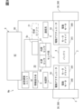
- FIG. 2 is a block diagram showing a functional configuration of the control system according to the first embodiment.
- 4 is a flowchart showing a control flow according to the first embodiment.
- FIG. 4 is a schematic diagram for explaining a control attitude according to the first embodiment.
- FIG. 4 is a schematic diagram for explaining a control attitude according to the first embodiment.
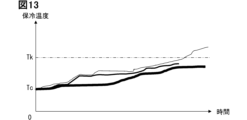
- 1 is a graph for explaining cold insulation efficiency according to the first embodiment.
- 1 is a graph for explaining cold insulation efficiency according to the first embodiment.
- 10 is a flowchart showing a control flow according to a second embodiment.
- 13 is a flowchart showing a control flow according to a third embodiment.
- 13 is a flowchart showing a control flow according to a third embodiment.
- 13 is a graph for explaining the determination of an optimum route according to the third embodiment.
- the control system 1 of the first embodiment shown in FIG. 1 controls the autonomous travel of an autonomous transport device Ma that stores an item Gc in a transport chamber 20 and transports it by autonomous travel, as shown in FIGS. 2 and 3.
- the autonomous transport device Ma is constructed so that it can travel autonomously in any direction along a horizontal plane.
- the autonomous transport device Ma transports items Gc that require refrigeration.
- the items Gc that require refrigeration may be, for example, at least one type of food among refrigerated items, frozen items, and items stored at room temperature.
- the items Gc that require refrigeration may be at least one type of items other than food, such as medicines, feed, solvents, solutions, miscellaneous items, building materials, and electronic devices.
- Such items Gc that require refrigeration may be loaded into the transport chamber 20 in a state where they are packed or wrapped in, for example, at least one type of cardboard box, polystyrene foam case, plastic case, plastic film, and the like.
- the autonomous transport device Ma may transport items Gc that do not require refrigeration, as long as it is constructed to be able to transport items Gc that require refrigeration.
- the autonomous transport device Ma may be a delivery vehicle or a delivery robot that autonomously travels on a travel path (i.e., a road) on an external route as a travel area, or on a travel path inside and outside a building in a smart city as a travel area, to deliver luggage as the item Gc.
- the autonomous transport device Ma may be a transport vehicle or a transport robot that autonomously travels on a travel path inside and outside a warehouse in a logistics facility as a travel area to transport luggage as the item Gc.
- the autonomous transport device Ma may be a food delivery robot that autonomously travels on a travel path in a restaurant or hospital as a travel area to deliver food and drink as the item Gc.
- the autonomous transport device Ma may be a disaster support robot that autonomously travels while searching for a travel path that can be traveled in a disaster area as a travel area, to transport supplies as the item Gc.
- the autonomous transport device Ma may of course be a device other than these.
- any type of autonomous transport device Ma may receive remote travel support or travel control from an external center.
- the autonomous transport device Ma includes a body 2, a drive system 3, a battery 4, a sensor system 5, a communication system 6, a map database 7, and an information presentation system 8.
- the body 2 is hollow and made of, for example, metal.
- the body 2 holds other components of the autonomous transport device Ma inside or across from the inside to the outside.
- the body 2 forms a transport chamber 20 to accommodate the goods Gc loaded from the outside onto the autonomous transport device Ma as the transport target.
- the transport chamber 20 may be configured to exhibit refrigeration performance for the goods Gc by being surrounded in a box shape by walls made of insulating material, for example as the internal space of a refrigerated container.
- the transport chamber 20 may be configured to be able to keep the goods Gc cool at or below a set temperature by the cooling function of a cooling unit 21 (see the two-dot chain line in Figure 3) mounted on the body 2.
- the cooling unit 21 may be an air conditioning unit that adjusts the air conditioning temperature of the transport chamber 20, or a refrigeration unit that refrigerates (or freezes) the goods Gc in the transport chamber 20.
- the drive system 3 includes wheels 30 and an electric actuator 34.
- a number of wheels 30 are supported by the body 2.
- Each wheel 30 is configured to be able to rotate independently.
- a pair of drive wheels 300 are each driven independently by a separate electric actuator 34.
- the running state of the autonomous transport device Ma is switched between straight running and turning running depending on the difference in rotational speed (i.e., the difference in the number of rotations per unit time) between these drive wheels 300.
- the autonomous transport device Ma is driven in a straight line.
- the turning radius of the autonomous transport device Ma when it is turned decreases in accordance with the increase in the rotational speed difference.
- the turning radius means the distance in a plan view between the vertical center line of the body 2 and the turning center of the turning drive, so turning drive in which the turning radius is effectively reduced to zero is point turning drive.
- the multiple wheels 30 may include at least one driven wheel that rotates following the driving wheel 300.
- At least one battery 4 shown in FIG. 3 is mounted on the body 2.
- the battery 4 is mainly composed of a storage battery such as a lithium ion battery.
- the battery 4 stores output power from the power generation unit 9 as power to be supplied to the electrical equipment in the body 2 by discharging.
- the battery 4 may store power to be supplied to the electrical equipment in the body 2 by discharging by charging from an external source.
- the battery 4 may store regenerated power from the electric actuator 34.
- the battery 4 is connected to the electric actuator 34, the sensor system 5, the communication system 6, the map database 7, the information presentation system 8, and the power generation unit 9, which are the destinations of the power supply, via a wire harness so that it can supply power.
- the battery 4 may also be connected to the cooling unit 21, when mounted on the body 2, via a wire harness so that it can supply power.
- a pair of electric actuators 34 are supported by the body 2.
- Each electric actuator 34 one on each side of the body 2, is mainly composed of an electric motor 340 and a motor driver 341.
- the electric motor 340 drives and rotates the corresponding drive wheel 300 independently.
- the motor driver 341 adjusts the current applied to the electric motor 340 of the same pair according to a current command value from the control system 1, thereby controlling the output of drive torque to the corresponding drive wheel 300 according to the current command value.
- Each electric actuator 34 may be equipped with a brake unit that applies braking to the corresponding drive wheel 300 while it is rotating.
- the sensor system 5 shown in Figures 2 and 3 acquires sensing information that can be used by the control system 1 by sensing the external and internal worlds of the autonomous transport device Ma. To that end, the components of the sensor system 5 are mounted in multiple locations on the body 2. Specifically, the sensor system 5 is composed of an external sensor 50 and an internal sensor 51.
- the external sensor 50 acquires external information as sensing information from the external world that is the surrounding environment of the autonomous transport device Ma.
- the external sensor 50 acquires external information by detecting objects that exist in the external world of the autonomous transport device Ma.
- the object detection type external sensor 50 is at least one of the following types: a camera, LiDAR (Light Detection and Ranging/Laser Imaging Detection and Ranging), radar, sonar, an ambient light sensor, and an impact sensor.
- the internal sensor 51 shown in FIG. 3 acquires internal information as sensing information from the internal world, which is the internal environment of the autonomous transport device Ma.
- the internal sensor 51 may be a physical quantity detection type that acquires internal information by detecting a specific physical quantity of motion in the internal world of the autonomous transport device Ma.
- the physical quantity detection type internal sensor 51 is at least one type of sensor, such as a speed sensor, an acceleration sensor, or an inertial sensor.
- the internal sensor 51 may be an indoor detection type that acquires internal information by detecting the inside of the transport chamber 20, which is the internal world of the autonomous transport device Ma.
- the indoor detection type internal sensor 51 is at least one type of sensor, such as a temperature sensor, a weight sensor, a pressure sensor, a camera, or an RFID (Radio Frequency Identifier) reader.
- the communication system 6 transmits and receives communication information usable by the control system 1 via wireless communication between the autonomous transport device Ma and the outside world.
- the communication system 6 may be of a positioning type that acquires communication information by receiving positioning signals from artificial satellites of the Global Navigation Satellite System (GNSS) that exist in the outside world of the autonomous transport device Ma.
- GNSS Global Navigation Satellite System
- the positioning type communication system 6 is, for example, a GNSS receiver.
- the communication system 6 may be of a V2X type that transmits and receives communication information between the autonomous transport device Ma and a V2X system that exists outside the autonomous transport device Ma.
- the V2X type communication system 6 is, for example, at least one of a Dedicated Short Range Communications (DSRC) communication device and a Cellular V2X (C-V2X) communication device.
- the communication system 6 may be of a terminal communication type that transmits and receives communication information between the autonomous transport device Ma and a mobile terminal that exists outside the autonomous transport device Ma.
- the terminal communication type communication system 6 is, for example, at least one of a Bluetooth (registered trademark) device, a Wi-Fi (registered trademark) device, and an infrared communication device.
- the map database 7 stores map information that can be used by the control system 1.
- the map database 7 includes at least one type of non-transitory tangible storage medium, such as a semiconductor memory, a magnetic medium, or an optical medium.
- the map database 7 may be a database of a locator that estimates the self-position of the autonomous transport device Ma.
- the map database 7 may be a database of a planning unit that plans the travel of the autonomous transport device Ma.
- the map database 7 may be composed of a combination of multiple types of these databases.
- the map database 7 acquires and stores the latest map information, for example, by communication with an external center.
- the map information is digitized in two or three dimensions as information representing the travel area of the autonomous transport device Ma.
- the three-dimensional map data it is preferable to adopt digital data of a high-precision map.
- the map information may be acquired as data downloaded to the map database 7 via the communication system 6 from an infrastructure database in an infrastructure system such as an external center.
- the map information may be acquired by associating the travel area with a plurality of three-dimensional voxels (i.e., three-dimensional grids) obtained by virtually dividing the travel area into a three-dimensional array, or by associating the travel area with a plurality of two-dimensional grids obtained by virtually dividing the travel area into two-dimensional tiles, each of which is linked to an individual spatial ID.
- three-dimensional voxels i.e., three-dimensional grids
- the map information stored in the map database 7 may include roadway information that indicates at least one of the following: position coordinates, size, shape, and road surface conditions for the roadway.
- the map information may include stationary object information that indicates at least one of the following: position coordinates, size, and shape for buildings, structures, and plants that face the roadway.
- the map information may include road marking information that indicates at least one of the following: position coordinates, size, and shape for signs, dividing lines, and traffic lights that are attached to the roadway as the roadway.
- the information presentation system 8 presents alarm information to people in the vicinity of the autonomous transport device Ma.
- the information presentation system 8 may present the alarm information by stimulating the vision of the people in the vicinity.
- the visual stimulation type information presentation system 8 is at least one of a monitor unit, a light-emitting unit, etc.
- the information presentation system 8 may present the alarm information by stimulating the hearing of the people in the vicinity.
- the auditory stimulation type information presentation system 8 is at least one of a speaker, a buzzer, a vibration unit, etc.
- the power generation unit 9 is equipped with a solar panel 90.
- the solar panel 90 is, for example, a silicon-based, compound-based, organic-based, or quantum dot-based panel that can convert the energy of received sunlight into electricity and output it.
- the solar panel 90 forms a light-receiving surface 92 for receiving sunlight.
- the solar panel 90 outputs electricity that is temporarily stored in the battery 4 by generating electricity in response to the reception of sunlight on the light-receiving surface 92.
- the output power from the solar panel 90 is used at least to store the item Gc that requires refrigeration in the transport chamber 20 and transport it by autonomous driving.
- the solar panel 90 is supported so that it can be driven freely relative to the body 2.
- at least the elevation angle of the azimuth angle in the horizontal plane and the elevation angle in the vertical plane which are the attitude angles of the solar panel 90 in the autonomous transport device Ma, can be adjusted by the attitude adjustment unit 91 mounted on the power generation unit 9.
- the control system 1 shown in FIG. 1 controls the autonomous driving of the autonomous transport device Ma along a planned future route while recognizing the external environment and the device's own position.
- the control system 1 is composed of at least one dedicated computer, including a computer mounted in the body 2.
- the dedicated computer constituting the control system 1 is connected to the electric actuator 34, battery 4, sensor system 5, communication system 6, map database 7, information presentation system 8, and power generation unit 9 via at least one of, for example, a LAN (Local Area Network) line, a wire harness, an internal bus, and a wireless communication line.
- the dedicated computer constituting the control system 1 may be connected to the cooling unit 21 when mounted in the body 2 via at least one of, for example, a LAN line, a wire harness, and an internal bus.
- the dedicated computer constituting the control system 1 may be a planning ECU (Electronic Control Unit) that plans future routes as a driving plan for the autonomous transport device Ma.
- the dedicated computer constituting the control system 1 may be an actuator ECU that controls the electric actuator 34 of the autonomous transport device Ma.
- the dedicated computer constituting the control system 1 may be a power supply ECU that controls the battery 4 of the autonomous transport device Ma.
- the dedicated computer constituting the control system 1 may be a sensing ECU that controls the sensor system 5 of the autonomous transport device Ma.
- the dedicated computer constituting the control system 1 may be a locator ECU that estimates the self-position of the autonomous transport device Ma based on the map database 7.
- the dedicated computer constituting the control system 1 may be an information presentation ECU that controls the information presentation system 8 of the autonomous transport device Ma.
- the dedicated computer constituting the control system 1 may be a power generation ECU that controls the power generation unit 9 of the autonomous transport device Ma.
- the dedicated computer constituting the control system 1 may be a computer outside the body 2 that constitutes, for example, an external center or mobile terminal capable of communicating via the communication system 6.
- the dedicated computer that constitutes the control system 1 has at least one memory 10 and one processor 12.
- the memory 10 is at least one type of non-transitory tangible storage medium, such as a semiconductor memory, a magnetic medium, or an optical medium, that non-temporarily stores computer-readable programs and data.
- the processor 12 includes at least one type of core, such as a CPU (Central Processing Unit), a GPU (Graphics Processing Unit), a RISC (Reduced Instruction Set Computer)-CPU, a DFP (Data Flow Processor), or a GSP (Graph Streaming Processor).
- the processor 12 executes a plurality of instructions contained in a control program stored in the memory 10 in order to control the autonomous traveling of the autonomous transport device Ma.
- the control system 1 constructs a plurality of functional blocks for controlling the autonomous traveling of the autonomous transport device Ma.
- the multiple functional blocks constructed in the control system 1 include a monitoring block 100 and a control block 110, as shown in FIG. 4.
- control method in which the control system 1 controls the autonomous travel of the autonomous transport device Ma by cooperation of these blocks 100 and 110 is executed according to the control flow shown in FIG. 5.
- the control flow of the first embodiment is executed repeatedly when the autonomous transport device Ma starts to transport an item Gc by autonomous travel after startup, until the device Ma arrives at the destination of the future route.
- each "S" in the control flow represents each step executed by multiple commands included in the control program.
- the monitoring block 100 acquires incident information Is regarding the incidence of sunlight on the autonomous transport device Ma.
- the incident information Is includes the sun direction Ds (see Figures 6 and 7) as the three-dimensional direction in which the sun exists as seen from the autonomous transport device Ma.
- the sun direction Ds is defined by both the azimuth angle in the horizontal plane and the elevation angle in the vertical plane at the control travel point that is the latest control target among the travel points in the future route planned for the autonomous transport device Ma.
- the incident information Is acquired in S10 may include, in addition to the sun direction Ds, at least one of the following: the altitude or position of the sun, the illuminance or amount of sunlight, weather information, and shade information on the future route.
- the incident information Is including at least the sun direction Ds may be acquired based on at least one of the necessary types: sensing information of the ambient light sensor as the external sensor 50, weather information which is communication information of the communication system 6, positioning information which is communication information of the communication system 6, map information of the map database 7, and self-position information of the locator ECU.
- sensing information of the ambient light sensor as the external sensor 50 weather information which is communication information of the communication system 6
- positioning information which is communication information of the communication system 6
- map information of the map database 7 map information of the map database 7
- self-position information of the locator ECU self-position information of the locator ECU.
- S20 is executed following the completion of execution of S10.
- the monitoring block 100 determines whether the environmental state outside the autonomous transport device Ma is in a sunshine state where sunlight is incident on the device Ma. At this time, the determination of the sunshine state is based on the incident information Is acquired by S10.
- S30 is executed.
- the control block 110 plans the driving posture of the autonomous transport device Ma during autonomous driving.
- the driving posture of the autonomous transport device Ma is planned to be an optimized control posture Ac for the control driving point that is the latest control target among the driving points in the future route planned for the autonomous transport device Ma.
- the control attitude Ac is defined as a travel attitude in which the transport chamber 20 is positioned in the opposite direction Dr to the sun direction Ds, with respect to the light receiving surface 92 of the solar panel 90 of the power generation unit 9, which is oriented in the sun direction Ds to receive sunlight, as shown in Figures 6 and 7. Therefore, in the control attitude Ac for which adjustment at the latest control travel point is planned, it is preferable that at least a part of the transport chamber 20 is positioned within the shadow cast in the opposite direction Dr by the solar panel 90, whose light receiving surface 92 is oriented in the sun direction Ds in accordance with the incident information Is acquired by S20.
- the attitude angle of the autonomous transport device Ma on the traveling path may be controlled by each electric actuator 34 in the horizontal plane, so that the light receiving surface 92 faces the sun direction Ds and the transport chamber 20 is positioned in the reverse direction Dr, thereby adjusting the control posture Ac.
- the attitude angle of the solar panel 90 of the autonomous transport device Ma may be controlled by the attitude adjustment unit 91 in at least the vertical plane out of the horizontal plane and the vertical plane, so that the light receiving surface 92 faces the sun direction Ds and the transport chamber 20 is positioned in the reverse direction Dr, thereby adjusting the control posture Ac.
- both the adjustment of the attitude angle of the autonomous transport device Ma on the traveling path and the adjustment of the attitude angle of the solar panel 90 of the autonomous transport device Ma may be considered.
- the control posture Ac which can be said to be a control target of the traveling posture, is set based on the correlation between the power generation efficiency Eg of the solar panel 90 in the power generation unit 9 and the cooling efficiency Ek of the goods Gc in the transport chamber 20 so as to control these efficiencies Eg and Ek. Therefore, the control posture Ac is set as a control target that maximizes the energy efficiency Ee correlated with the efficiencies Eg and Ek according to the following equation 1 using weights ⁇ g and ⁇ k for each of the efficiencies Eg and Ek.
- at least one of the reference posture Ab in which the light receiving surface 92 is perpendicular to the sun direction Ds as shown in Fig. 6 and the inclined posture As in which the light receiving surface 92 is inclined with respect to the sun direction Ds as shown in Fig. 7 is assumed as a candidate for the control posture Ac.
- the power generation efficiency Eg is obtained as a power generation performance index by taking the power generated by the solar panel 90 in each attitude Ab, As as a relative ratio based on the power generated in the reference attitude Ab.
- the power generation efficiency Eg in each attitude Ab is obtained based on power generation related parameters including at least the sun direction Ds, such as the sun direction Ds, the altitude or position of the sun, the illuminance or incidence of sunlight, shade information on the future route, the temperature of the solar panel 90, and the power generation performance of the power generation unit 9. Therefore, when obtaining the power generation efficiency Eg, it is preferable to grasp the power generation related parameters based on at least one of the necessary types, such as the incidence information Is obtained in S10 and the status detection information of the power generation unit 9.
- the cooling efficiency Ek is obtained as a cooling performance index by a relative ratio of the temperature rise time, which is defined as the rise time per unit temperature rise of the item Gc in each posture Ab, As, to the temperature rise time in the reference posture Ab as a reference.
- the cooling efficiency Ek may be obtained by predicting the temperature rise time in each posture Ab, As according to the cooling temperature Tc before loading, as shown in Figures 8 and 9, for the cooling temperature of the item Gc cooled before loading in the transport chamber 20.
- the cooling efficiency Ek may be obtained by predicting the temperature rise time in each posture Ab, As according to the cooling performance of the unit 21, as shown in Figure 9, for the cooling temperature of the item Gc that can be cooled during autonomous driving in the transport chamber 20 when the cooling unit 21 is installed.
- Figures 8 and 9 show a schematic diagram of the correlation between the time and the cold storage temperature, starting from immediately after the loading of the item Gc, but in reality, the change in the cold storage temperature over time according to the control posture Ac according to the previous control flow should be taken into account when predicting the temperature rise time (see Figure 12 in the third embodiment described below).
- the cold storage efficiency Ek in each position Ab As is obtained based on cold storage related parameters including at least the direction Ds or Dr, such as the sun direction Ds or the opposite direction Dr, information on the shadow cast by the solar panel 90, the outside environmental temperature, the initial temperature of the item Gc at the time of loading, the initial temperature inside the transport chamber 20 at the time of loading, the cooling performance in the transport chamber 20, and shade information on the future route. Therefore, when obtaining the cold storage efficiency Ek, the cold storage related parameters may be understood based on at least one of the necessary types, such as the incident information Is obtained by S10, the temperature information of the temperature sensor as the internal sensor 51, and the cooling condition information of the item Gc before loading.
- the energy efficiency Ee based on each of the efficiencies Eg and Ek is obtained for each of the postures Ab and As that are candidates for the control posture Ac.
- the weights ⁇ g and ⁇ k for each of the efficiencies Eg and Ek in Equation 1 that gives the energy efficiency Ee as described above are set on a rule basis using, for example, a simulation model, a function, a map, or a table.
- the weight ⁇ g of the power generation efficiency Eg may be adjusted to be greater than the weight ⁇ k of the cold storage efficiency Ek when a condition is met, such as the stored power in the battery 4 dropping below or below a threshold, or the opposite relationship may be adjusted when the condition is not met.
- the weight ⁇ g of the power generation efficiency Eg may be adjusted to be greater than the weight ⁇ k of the cold storage efficiency Ek when a condition is met, such as the stored power in the battery 4 dropping below or below a threshold, such as the opposite relationship may be adjusted when the condition is not met.
- the weight ⁇ k of the cold storage efficiency Ek may be adjusted to be greater than the weight ⁇ g of the power generation efficiency Eg when a condition is met, such as the temperature in the transport chamber 20 rising above or exceeding a threshold value, or the opposite relationship may be adjusted if the condition is not met.
- the weight ⁇ k of the cold storage efficiency Ek may be adjusted to be greater than the weight ⁇ g of the power generation efficiency Eg when a condition is met, such as the cooling temperature of the goods Gc cooled before loading being above or exceeding a threshold value, or the opposite relationship may be adjusted if the condition is not met.
- the optimal posture that maximizes the energy efficiency Ee is selected as the control posture Ac from among the candidate postures Ab and As.
- the posture Ab or As with the highest possible energy efficiency Ee less than the maximum efficiency may be selected as the optimal control posture Ac based on at least one of the following: continuity from the control posture Ac selected by S30 executed in the previous control flow, and posture restrictions according to the driving environment at each driving point.
- the weights ⁇ g and ⁇ k for each efficiency Eg and Ek may be adjusted by a machine learning model to maximize the energy efficiency Ee, and the control posture Ac corresponding to the maximized energy efficiency Ee may be selected.
- S40 is executed following the completion of execution of S30.
- the control block 110 adjusts the traveling posture of the autonomous transport device Ma at the latest controlled traveling point according to the control posture Ac selected in S30.
- the traveling speed of the autonomous transport device Ma may be increased to allow air cooling of the solar panel 90 by the traveling wind.
- the current execution of the control flow ends upon completion of execution of S40.
- S50 is executed.
- the control block 110 adjusts the running posture of the autonomous transport device Ma at the latest controlled running point.
- the running posture is controlled to the latest posture among the control postures Ac selected by S30 executed in the previous control flow after the device Ma was started, or to the default posture when S30 has never been executed even once in the previous control flow.
- the current execution of the control flow also ends upon completion of execution of S50.
- the autonomous transport device Ma which receives power from the power generation unit 9 that receives sunlight and generates power, is controlled to travel autonomously.
- incident information Is regarding the incidence of sunlight on the autonomous transport device Ma is acquired, and the traveling posture of the autonomous transport device Ma during autonomous travel is adjusted according to the incident information Is.
- the traveling posture is adjusted to a control posture Ac in which the transport chamber 20 is positioned in the opposite direction Dr to the solar direction Ds with respect to the light receiving surface 92 that is oriented in accordance with the incident information Is in the solar direction Ds for receiving sunlight in the power generation unit 9.
- the attitude angle of the autonomous transport device Ma on the travel path may be controlled so that the light receiving surface 92 of the power generation unit 9 is oriented in the solar direction Ds of sunlight.
- This makes it possible to accurately align the light receiving surface 92 with the solar direction Ds to ensure power generation efficiency Eg, and to adjust the position of the transport chamber 20 in the opposite direction Dr to the solar direction Ds with respect to the light receiving surface 92 to ensure cooling efficiency Ek, by controlling the attitude angle of the entire autonomous transport device Ma. This makes it possible to increase the reliability of energy savings.
- the attitude angle of the power generation unit 9 in the autonomous transport device Ma may be controlled so that the light receiving surface 92 of the power generation unit 9 is oriented in the solar direction Ds of the sunlight.
- This allows accurate alignment of the light receiving surface 92 to the solar direction Ds in order to ensure power generation efficiency Eg, and accurate adjustment of the position of the transport chamber 20 in the opposite direction Dr to the solar direction Ds with respect to the light receiving surface 92 in order to ensure cooling efficiency Ek, by individual attitude angle control of the power generation unit 9. This makes it possible to increase the reliability of energy savings.
- the traveling posture of the autonomous transport device Ma may be adjusted to a control posture Ac that controls the cooling efficiency Ek of the cooled item Gc before loading into the transport chamber 20.
- This makes it possible to control the cooling efficiency Ek in the transport chamber 20 in the direction Dr opposite the sun direction Ds with respect to the light receiving surface 92 to the optimal efficiency for the cooled item Gc, thereby saving energy.
- it is also possible to promote energy savings by reducing the cooling temperature and/or cooling time of the item Gc before loading as much as possible, while optimally controlling the cooling efficiency Ek in accordance with this reduction.
- the traveling posture of the autonomous transport device Ma may be adjusted to a control posture Ac that controls the cooling efficiency Ek of the coolable item Gc during autonomous travel in the transport chamber 20.
- a control posture Ac that controls the cooling efficiency Ek of the coolable item Gc during autonomous travel in the transport chamber 20.
- the traveling posture of the autonomous transport device Ma is adjusted to a control posture Ac that maximizes the energy efficiency Ee, which correlates with the power generation efficiency Eg of the power generation unit 9 and the cooling efficiency Ek of the item Gc.
- the power generation efficiency Eg of the power generation unit 9 in which the light receiving surface 92 faces the sun direction Ds, and the cooling efficiency Ek of the transport chamber 20 located in the opposite direction Dr from the sun direction Ds with respect to the light receiving surface 92 can be optimized by adjusting the control posture Ac from the perspective of maximizing the energy efficiency Ee. Therefore, it is possible to achieve energy savings according to the traveling environment of the autonomous transport device Ma.
- the second embodiment is a modification of the first embodiment.
- the control flow of the second embodiment shown in Fig. 10 is executed once after the autonomous transport device Ma is started up.
- the monitoring block 100 selects a planned travel point for which the control posture Ac is planned in advance from among a plurality of travel points that are planned at set distance intervals or set time intervals on the future route of the autonomous transport device Ma.
- the planned travel points are preferably selected one by one in order of furthest or nearest to the destination of the future route each time S200 is executed.
- S210 is executed following the completion of execution of S200.
- the monitoring block 100 predicts the sun direction Ds of sunlight on the solar panel 90 of the power generation unit 9 as the incident information Is for the latest planned travel point selected by S200.
- the sun direction Ds which is defined in the same manner as S20 in the first embodiment, may be predicted based on at least one of the required types, for example, weather information which is communication information of the communication system 6, positioning information which is communication information of the communication system 6, map information of the map database 7, and self-position information of the locator ECU.
- the prediction of the sun direction Ds may be skipped.
- S220 is executed following completion of execution of S210.
- the monitoring block 100 predicts whether the environmental state in the outside world of the autonomous transport device Ma will be a sunlight state in which sunlight is incident on the device Ma, for the planned travel point selected in S200. At this time, the prediction of the sunlight state is based on the incident information Is obtained in S210.
- S230 is executed.
- the control block 110 plans a control posture Ac corresponding to S30 of the first embodiment as the driving posture of the autonomous transport device Ma in autonomous driving for the latest planned driving point selected by S200.
- the driving posture of the autonomous transport device Ma is planned for the latest planned point so that it is adjusted to the control posture Ac that controls the power generation efficiency Eg of the power generation unit 9 and the cooling efficiency Ek of the item Gc according to the prediction result of the sun direction Ds by S210.
- S231 is executed following the completion of execution of S230.
- the monitoring block 100 determines whether or not the planning of the control posture Ac is complete by presetting all travel points in the future route planned for the autonomous transport device Ma as planned travel points. If a negative determination is made as a result, the control flow returns to S200, and the next planned travel point is selected from among the travel points where the planning of the control posture Ac is incomplete.
- control block 110 plans the traveling posture of the autonomous transport device Ma in autonomous traveling to a control posture Ac defined differently from S230 for the planned traveling point selected in S200.
- the control posture Ac in S232 is defined as the selected posture for the planned traveling point closest to this time among the control postures Ac selected by S230 already executed in the current control flow, or as the default posture when S230 has never been executed in the current control flow. Even if S232 is passed through in this way, if a negative judgment is made in S231, the control flow returns to S200.
- S240 is executed.
- the monitoring block 100 determines whether or not the autonomous transport device Ma has started transporting the item Gc by autonomous travel. As a result, execution of S240 is repeated as long as a negative determination is made.
- S241 is executed.
- the control block 110 determines whether the latest controlled driving point by autonomous driving has reached any of the planned driving points of the control posture Ac planned in S230 or S232. As a result, while a negative determination is made, execution of S241 is repeated while maintaining autonomous driving control in the most recently adjusted control posture Ac.
- control block 110 adjusts the traveling posture of the autonomous transport device Ma in accordance with S40 of the first embodiment so that the traveling posture follows the control posture Ac at the planned traveling point corresponding to the most recently reached controlled traveling point.
- S200 to S241 may be re-executed in parallel with S242 to re-plan the control posture Ac for each travel point.
- the machine learning model may be updated based on the optimal value and the observed value.
- the predicted values of each efficiency Eg, Ek in S230 and the optimal value of the energy efficiency Ee based thereon may be obtained and compared for multiple autonomous transport devices Ma by a dedicated computer constituting at least a part of the control system 1, for example, at an external center, to select the autonomous transport device Ma that is optimal for the future route.
- control block 110 determines whether the latest controlled driving point by autonomous driving has reached the destination on the future route. If a negative determination is made as a result, the control flow returns to S241. On the other hand, if a positive determination is made, the current execution of the control flow ends.
- the sun direction Ds for each travel point on the future route of the autonomous transport device Ma is predicted as incident information Is.
- the attitude of the light receiving surface 92 which is adjusted to the predicted result of the sun direction Ds in order to ensure power generation efficiency Eg
- the traveling posture of the autonomous transport device Ma is adjusted to a control posture Ac that controls the power generation efficiency Eg of the power generation unit 9 and the cooling efficiency Ek of the item Gc for each traveling point on the future route of the autonomous transport device Ma according to the predicted result of the sun direction Ds.
- the posture of the light receiving surface 92 that is adjusted to the predicted result of the sun direction Ds in order to control the power generation efficiency Eg to the optimal efficiency, and the position of the transport chamber 20 that is adjusted to the opposite direction Dr from the predicted result of the sun direction Ds with respect to the light receiving surface 92 in order to control the cooling efficiency Ek to the optimal efficiency can be planned in advance for each traveling point on the future route. Therefore, it is possible to increase the reliability of energy saving according to the traveling environment of the autonomous transport device Ma.
- the third embodiment is a modification of the second embodiment.
- the control flow of the third embodiment shown in Fig. 11 and 12 is executed once after the autonomous transport device Ma is started up.
- the monitoring block 100 selects a posture planning route that plans a control posture A for each travel point from among multiple travel routes planned as future routes for the autonomous transport device Ma.
- a posture planning route that plans a control posture A for each travel point from among multiple travel routes planned as future routes for the autonomous transport device Ma.
- S300 when execution of S300 is completed, S200 to S232 of the second embodiment are executed for the posture planning route selected by S300. As a result, if a positive determination is made in S231, S330 is executed. In S330, the monitoring block 100 determines whether or not all future routes planned for the autonomous transport device Ma have been selected as posture planning routes, and the planning of the control posture Ac for each traveling point for all of these routes is complete. As a result, if a negative determination is made, the control flow returns to S300, and the next posture planning route is selected from the future routes for which the planning of the control posture Ac for each traveling point is incomplete.
- S340 the control block 100 determines an optimal route in terms of energy efficiency Ee from among all future routes for which planning of control postures Ac for each driving point has been completed as posture planning routes.
- the optimal route is determined based on, for example, the average value of the energy efficiency Ee corresponding to the control posture Ac for each driving point.
- posture planning routes for which the predicted cold storage temperature of the item Gc before reaching the destination is equal to or exceeds the allowable temperature Tk may be excluded from the optimal route candidates. Note that each line graph of different thickness in FIG. 13 individually indicates the correlation between time and cold storage temperature for each posture planning route.
- a future route (specifically, an optimal route) is determined in which the traveling posture is adjusted to the control posture Ac for each traveling point based on the power generation efficiency Eg of the power generation unit 9 and the cooling efficiency Ek of the goods Gc for each traveling point in each of the multiple planned future routes.
- This allows the posture of the light receiving surface 92 to be aligned with the predicted result of the sun direction Ds, and each of the efficiencies Eg, Ek used to adjust the position of the transport chamber 20 in the opposite direction Dr to the predicted result of the sun direction Ds can also be effectively used in route determination.
- the dedicated computer constituting the control system 1 may have at least one of a digital circuit and an analog circuit as a processor.
- the digital circuit is at least one of the following types: ASIC (Application Specific Integrated Circuit), FPGA (Field Programmable Gate Array), SOC (System on a Chip), PGA (Programmable Gate Array), and CPLD (Complex Programmable Logic Device).
- ASIC Application Specific Integrated Circuit
- FPGA Field Programmable Gate Array
- SOC System on a Chip
- PGA Programmable Gate Array
- CPLD Complex Programmable Logic Device
- the solar panel 90 may be fixed in position relative to the body 2.
- a control posture Ac that controls only one of the efficiencies Eg and Ek may be selected.
- a processing circuit e.g., a processing ECU, etc.
- a semiconductor device e.g., a semiconductor chip, etc.
- a control device that is configured to be mountable on the autonomous transport device Ma and has at least one processor 12 and one memory 10.
- a control system for controlling the autonomous travel of an autonomous transport device (Ma) that receives power from a power generation unit (9) that receives sunlight and generates power in order to store an item (Gc) that requires refrigeration in a transport chamber (20) and transport the item by autonomous travel comprising: The processor, Acquiring incident information (Is) regarding the incidence of the sunlight on the autonomous transport device; and adjusting the driving posture of the autonomous transport device during the autonomous driving to a control posture (Ac) that positions the transport chamber in a direction opposite to the sun direction (Ds) with respect to a light receiving surface (92) that is oriented in accordance with the incident information toward the sun direction (Ds) for receiving the sunlight in the power generation unit.
- the control system according to technical idea 1 includes controlling an attitude angle of the autonomous transport device on a travel path to orient the light receiving surface toward the sun.
- Adjusting the running posture includes:
- the control system according to technical idea 1 or 2 includes controlling the attitude angle of the power generation unit in the autonomous transport device to orient the light receiving surface toward the sun.
- Adjusting the running posture includes: A control system described in any one of technical ideas 1 to 3, which includes adjusting the running posture to the control posture that controls the cooling efficiency of the items that have been cooled before being loaded into the transport chamber.
- Adjusting the running posture includes: A control system described in any one of technical ideas 1 to 4, which includes adjusting the driving posture to the control posture that controls the cooling efficiency of the items that can be cooled during the autonomous driving in the transport chamber.
- Adjusting the running posture includes: A control system described in any one of technical ideas 1 to 5, which includes adjusting the driving posture to the control posture that maximizes energy efficiency that correlates with the power generation efficiency of the power generation unit and the cooling efficiency of the goods.
- the acquiring of the incident information includes: A control system described in any one of technical ideas 1 to 6, which includes predicting the sun direction at each traveling point on the future route of the autonomous transport device as the incidence information.
- Adjusting the running posture includes: A control system as described in technical idea 7, which includes adjusting the driving posture to the control posture that controls the power generation efficiency of the power generation unit and the cooling efficiency of the items at each driving point in accordance with the predicted result of the sun direction.
- Adjusting the running posture includes: A control system as described in technical idea 7 or 8, which includes determining the future route by adjusting the driving posture to the control posture for each driving point based on the power generation efficiency of the power generation unit and the cooling efficiency of the items at each driving point in each of the multiple planned future routes.
Landscapes
- Engineering & Computer Science (AREA)
- Power Engineering (AREA)
- Automation & Control Theory (AREA)
- Remote Sensing (AREA)
- Physics & Mathematics (AREA)
- General Physics & Mathematics (AREA)
- Radar, Positioning & Navigation (AREA)
- Aviation & Aerospace Engineering (AREA)
- Transportation (AREA)
- Mechanical Engineering (AREA)
- Control Of Position, Course, Altitude, Or Attitude Of Moving Bodies (AREA)
- Direct Current Feeding And Distribution (AREA)
- Electric Propulsion And Braking For Vehicles (AREA)
Abstract
Ce système de commande est destiné à commander le déplacement autonome d'un dispositif de transport autonome (Ma), auquel une puissance est fournie afin de recevoir un article nécessitant un stockage à froid dans une chambre de transport (20) et de transporter l'article par un déplacement autonome, la puissance étant fournie à partir d'une unité de génération de puissance (9) qui reçoit la lumière solaire et génère une puissance. Le système de commande comprend un processeur configuré pour exécuter : l'acquisition d'informations d'incidence sur l'incidence de la lumière solaire sur le dispositif de transport autonome (Ma) ; et le réglage d'une posture de déplacement du dispositif de transport autonome (Ma) pendant un déplacement autonome vers une posture de commande (Ac) dans laquelle la chambre de transport (20) est positionnée dans une direction opposée (Dr) à une direction du soleil (Ds) par rapport à une surface de réception de lumière (92) dirigée en fonction des informations d'incidence dans la direction du soleil (Ds) afin de recevoir la lumière solaire dans l'unité de génération de puissance.
Priority Applications (1)
| Application Number | Priority Date | Filing Date | Title |
|---|---|---|---|
| CN202480039410.9A CN121335815A (zh) | 2023-06-16 | 2024-05-21 | 控制系统、控制装置、控制方法、控制程序 |
Applications Claiming Priority (2)
| Application Number | Priority Date | Filing Date | Title |
|---|---|---|---|
| JP2023099403A JP2024180005A (ja) | 2023-06-16 | 2023-06-16 | 制御システム、制御装置、制御方法、制御プログラム |
| JP2023-099403 | 2023-06-16 |
Publications (1)
| Publication Number | Publication Date |
|---|---|
| WO2024257560A1 true WO2024257560A1 (fr) | 2024-12-19 |
Family
ID=93851732
Family Applications (1)
| Application Number | Title | Priority Date | Filing Date |
|---|---|---|---|
| PCT/JP2024/018613 Ceased WO2024257560A1 (fr) | 2023-06-16 | 2024-05-21 | Système de commande, dispositif de commande, procédé de commande et programme de commande |
Country Status (3)
| Country | Link |
|---|---|
| JP (1) | JP2024180005A (fr) |
| CN (1) | CN121335815A (fr) |
| WO (1) | WO2024257560A1 (fr) |
Cited By (1)
| Publication number | Priority date | Publication date | Assignee | Title |
|---|---|---|---|---|
| JP7712640B1 (ja) * | 2025-04-06 | 2025-07-24 | 佑斗 井澤 | 機械、システム |
Citations (3)
| Publication number | Priority date | Publication date | Assignee | Title |
|---|---|---|---|---|
| US10303171B1 (en) * | 2016-09-29 | 2019-05-28 | Amazon Technologies, Inc. | Autonomous ground vehicles providing ordered items in pickup areas |
| CN111412923A (zh) * | 2020-04-10 | 2020-07-14 | 新石器慧通(北京)科技有限公司 | 一种选择行驶路线的方法、装置及无人车 |
| US20210341914A1 (en) * | 2020-04-30 | 2021-11-04 | Roger Flemming | Solar Powered Cooler Assembly |
-
2023
- 2023-06-16 JP JP2023099403A patent/JP2024180005A/ja active Pending
-
2024
- 2024-05-21 WO PCT/JP2024/018613 patent/WO2024257560A1/fr not_active Ceased
- 2024-05-21 CN CN202480039410.9A patent/CN121335815A/zh active Pending
Patent Citations (3)
| Publication number | Priority date | Publication date | Assignee | Title |
|---|---|---|---|---|
| US10303171B1 (en) * | 2016-09-29 | 2019-05-28 | Amazon Technologies, Inc. | Autonomous ground vehicles providing ordered items in pickup areas |
| CN111412923A (zh) * | 2020-04-10 | 2020-07-14 | 新石器慧通(北京)科技有限公司 | 一种选择行驶路线的方法、装置及无人车 |
| US20210341914A1 (en) * | 2020-04-30 | 2021-11-04 | Roger Flemming | Solar Powered Cooler Assembly |
Cited By (1)
| Publication number | Priority date | Publication date | Assignee | Title |
|---|---|---|---|---|
| JP7712640B1 (ja) * | 2025-04-06 | 2025-07-24 | 佑斗 井澤 | 機械、システム |
Also Published As
| Publication number | Publication date |
|---|---|
| JP2024180005A (ja) | 2024-12-26 |
| CN121335815A (zh) | 2026-01-13 |
Similar Documents
| Publication | Publication Date | Title |
|---|---|---|
| US9939284B2 (en) | Autonomous vehicle lane routing and navigation | |
| CN109415122B (zh) | 用于自动化车辆和无人机递送的系统、方法和装置 | |
| US20210229570A1 (en) | Predictive remote thermal managment | |
| US10115305B2 (en) | Optimizing autonomous car's driving time and user experience using traffic signal information | |
| US11820504B2 (en) | Taxi of unmanned aerial vehicles during package delivery | |
| US9776528B2 (en) | Electric vehicle range prediction | |
| CN109564430B (zh) | 移动体引导系统、移动体、引导装置以及计算机程序 | |
| US9550582B2 (en) | Multi-zone battery exchange system | |
| US10095242B1 (en) | Invertible drone for selective power capture | |
| US20190009756A1 (en) | System and Method for Itinerant Power Source for Vehicles | |
| CN116830057A (zh) | 无人机(uav)集群控制 | |
| ES2883847T3 (es) | Prevención de colisiones de vehículos | |
| US20150345971A1 (en) | Synchronously updated vehicle transportation network information for autonomous vehicle routing and navigation | |
| CN115465125B (zh) | 一种基于无线充电技术的auv集群水下能量救援方法 | |
| CN111886611B (zh) | 用于自主运载工具的批路线规划的计算框架 | |
| US20190009916A1 (en) | Invertible Drone for Selective Power Capture | |
| WO2024257560A1 (fr) | Système de commande, dispositif de commande, procédé de commande et programme de commande | |
| US12377881B2 (en) | Delivery hand off procedure when electric vehicle (EV) is about to lose power | |
| Bayramov | Unmanned aerial vehicle reconnaissance flight in the energy saving mode | |
| US20200372417A1 (en) | On-Demand Travel Through a Transportation Network | |
| US20250189984A1 (en) | Navigation system, navigation method, and navigation program | |
| JP2026065551A (ja) | 制御システム、制御方法、制御プログラム | |
| JP2023169034A (ja) | 搬送処理システム、搬送処理装置、自律搬送車両、搬送処理方法、搬送処理プログラム | |
| JP2024053323A (ja) | 無人航空機の制御システム、及び無人航空機の制御プログラム | |
| HK40009443B (en) | Vehicle collision avoidance |
Legal Events
| Date | Code | Title | Description |
|---|---|---|---|
| 121 | Ep: the epo has been informed by wipo that ep was designated in this application |
Ref document number: 24823182 Country of ref document: EP Kind code of ref document: A1 |
|
| NENP | Non-entry into the national phase |
Ref country code: DE |