WO2024257601A1 - 端末装置及び方法 - Google Patents
端末装置及び方法 Download PDFInfo
- Publication number
- WO2024257601A1 WO2024257601A1 PCT/JP2024/019516 JP2024019516W WO2024257601A1 WO 2024257601 A1 WO2024257601 A1 WO 2024257601A1 JP 2024019516 W JP2024019516 W JP 2024019516W WO 2024257601 A1 WO2024257601 A1 WO 2024257601A1
- Authority
- WO
- WIPO (PCT)
- Prior art keywords
- terminal device
- unit
- authentication
- sensor
- authentication process
- Prior art date
- Legal status (The legal status is an assumption and is not a legal conclusion. Google has not performed a legal analysis and makes no representation as to the accuracy of the status listed.)
- Ceased
Links
Images



Classifications
-
- G—PHYSICS
- G06—COMPUTING OR CALCULATING; COUNTING
- G06F—ELECTRIC DIGITAL DATA PROCESSING
- G06F21/00—Security arrangements for protecting computers, components thereof, programs or data against unauthorised activity
- G06F21/30—Authentication, i.e. establishing the identity or authorisation of security principals
- G06F21/31—User authentication
- G06F21/34—User authentication involving the use of external additional devices, e.g. dongles or smart cards
-
- A—HUMAN NECESSITIES
- A61—MEDICAL OR VETERINARY SCIENCE; HYGIENE
- A61B—DIAGNOSIS; SURGERY; IDENTIFICATION
- A61B5/00—Measuring for diagnostic purposes; Identification of persons
-
- A—HUMAN NECESSITIES
- A61—MEDICAL OR VETERINARY SCIENCE; HYGIENE
- A61B—DIAGNOSIS; SURGERY; IDENTIFICATION
- A61B5/00—Measuring for diagnostic purposes; Identification of persons
- A61B5/02—Detecting, measuring or recording for evaluating the cardiovascular system, e.g. pulse, heart rate, blood pressure or blood flow
- A61B5/021—Measuring pressure in heart or blood vessels
- A61B5/0215—Measuring pressure in heart or blood vessels by means inserted into the body
-
- G—PHYSICS
- G06—COMPUTING OR CALCULATING; COUNTING
- G06F—ELECTRIC DIGITAL DATA PROCESSING
- G06F21/00—Security arrangements for protecting computers, components thereof, programs or data against unauthorised activity
- G06F21/30—Authentication, i.e. establishing the identity or authorisation of security principals
- G06F21/31—User authentication
-
- G—PHYSICS
- G06—COMPUTING OR CALCULATING; COUNTING
- G06F—ELECTRIC DIGITAL DATA PROCESSING
- G06F21/00—Security arrangements for protecting computers, components thereof, programs or data against unauthorised activity
- G06F21/30—Authentication, i.e. establishing the identity or authorisation of security principals
- G06F21/31—User authentication
- G06F21/32—User authentication using biometric data, e.g. fingerprints, iris scans or voiceprints
-
- G—PHYSICS
- G06—COMPUTING OR CALCULATING; COUNTING
- G06F—ELECTRIC DIGITAL DATA PROCESSING
- G06F21/00—Security arrangements for protecting computers, components thereof, programs or data against unauthorised activity
- G06F21/30—Authentication, i.e. establishing the identity or authorisation of security principals
- G06F21/45—Structures or tools for the administration of authentication
-
- H—ELECTRICITY
- H04—ELECTRIC COMMUNICATION TECHNIQUE
- H04L—TRANSMISSION OF DIGITAL INFORMATION, e.g. TELEGRAPHIC COMMUNICATION
- H04L63/00—Network architectures or network communication protocols for network security
- H04L63/08—Network architectures or network communication protocols for network security for authentication of entities
- H04L63/0853—Network architectures or network communication protocols for network security for authentication of entities using an additional device, e.g. smartcard, SIM or a different communication terminal
-
- H—ELECTRICITY
- H04—ELECTRIC COMMUNICATION TECHNIQUE
- H04W—WIRELESS COMMUNICATION NETWORKS
- H04W12/00—Security arrangements; Authentication; Protecting privacy or anonymity
- H04W12/06—Authentication
-
- G—PHYSICS
- G06—COMPUTING OR CALCULATING; COUNTING
- G06F—ELECTRIC DIGITAL DATA PROCESSING
- G06F2221/00—Indexing scheme relating to security arrangements for protecting computers, components thereof, programs or data against unauthorised activity
- G06F2221/21—Indexing scheme relating to G06F21/00 and subgroups addressing additional information or applications relating to security arrangements for protecting computers, components thereof, programs or data against unauthorised activity
- G06F2221/2139—Recurrent verification
-
- H—ELECTRICITY
- H04—ELECTRIC COMMUNICATION TECHNIQUE
- H04L—TRANSMISSION OF DIGITAL INFORMATION, e.g. TELEGRAPHIC COMMUNICATION
- H04L63/00—Network architectures or network communication protocols for network security
- H04L63/08—Network architectures or network communication protocols for network security for authentication of entities
- H04L63/0861—Network architectures or network communication protocols for network security for authentication of entities using biometrical features, e.g. fingerprint, retina-scan
-
- H—ELECTRICITY
- H04—ELECTRIC COMMUNICATION TECHNIQUE
- H04W—WIRELESS COMMUNICATION NETWORKS
- H04W12/00—Security arrangements; Authentication; Protecting privacy or anonymity
- H04W12/40—Security arrangements using identity modules
- H04W12/47—Security arrangements using identity modules using near field communication [NFC] or radio frequency identification [RFID] modules
Definitions
- This disclosure relates to a terminal device and method.
- This disclosure therefore provides a mechanism that can prevent unauthorized use of a terminal device that is inserted into the body.
- the terminal device of the present disclosure includes an authentication unit, a communication unit, a detection unit, and a stop processing unit.
- the authentication unit executes authentication processing for communicating with other devices.
- the communication unit communicates with the other devices if the authentication processing is successful.
- the detection unit detects when the device inserted into the body is removed from the body.
- the stop processing unit stops the authentication processing by the authentication unit when the removal from the body is detected.
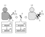
- FIG. 10 is a diagram illustrating an example of a method of using a terminal device.
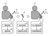
- 11 is a diagram for explaining an example of a stop process according to a proposed technique of the present disclosure.
- FIG. 11 is a diagram for explaining an example of a restart process according to a proposed technique of the present disclosure.
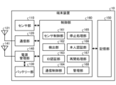
- FIG. FIG. 2 is a block diagram illustrating an example of a functional configuration of a terminal device according to an embodiment of the present disclosure.
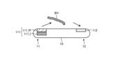
- FIG. 1 illustrates an example PPG sensor according to an embodiment of the present disclosure.
- FIG. 1 illustrates an example of an ECG sensor according to an embodiment of the present disclosure.
- 1 is a block diagram illustrating an example of a functional configuration of a communication device according to an embodiment of the present disclosure.
- 11 is a sequence diagram illustrating an example of a flow of an authentication process according to an embodiment of the present disclosure.
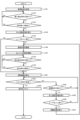
- 11 is a flowchart illustrating an example of a first processing flow according to an embodiment of the present disclosure.
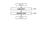
- 11 is a flowchart showing an example of a flow of an identity authentication process according to an embodiment of the present disclosure.
- 11 is a flowchart illustrating an example of a flow of a communication process according to an embodiment of the present disclosure.
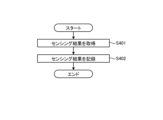
- 11 is a flowchart showing an example of a flow of a sensing process according to an embodiment of the present disclosure.
- 13 is a flowchart illustrating an example of a second processing flow according to an embodiment of the present disclosure.
- One or more of the embodiments (including examples, variations, and application examples) described below can be implemented independently. However, at least a portion of the embodiments described below may be implemented in appropriate combination with at least a portion of another embodiment. These embodiments may include novel features that are different from one another. Thus, these embodiments may contribute to solving different purposes or problems and may provide different effects.
- FIG. 1 is a diagram explaining an example of how to use the terminal device 10a.
- the terminal device 10a As shown in the left diagram of FIG. 1, the terminal device 10a is inserted inside the body of the user U_A (in FIG. 1, the arm, the back of the hand, etc.).
- the terminal device 10a communicates with a communication device 20a located outside the body of the user U_A. This allows the user U_A to perform electronic payments, personal identification, etc. using the terminal device 10a.
- the terminal device 10a is removed from the body of the user U_A.
- the terminal device 10a does not detect that it has been removed. Therefore, even if the terminal device 10a is subsequently inserted into a user U_B different from the user U_A, as shown in the right diagram of Figure 1, the terminal device 10a can communicate with the communication device 20a.
- the terminal device 10a by removing the terminal device 10a from the body and inserting it into the user U_B, the user U_B can pose as the user U_A. It is desirable to prevent such unauthorized use of the terminal device 10a.
- the terminal device detects when it is inserted into the body and when it is removed from the body, and when it is removed from the body, it is made unusable. For example, when the terminal device performs an authentication process for communicating with a communication device, the terminal device is made unusable by making the authentication process unusable.
- FIG. 2 is a diagram for explaining an example of the stop processing related to the proposed technology of the present disclosure.
- the stop processing is executed by the terminal device 10.
- the terminal device 10 is, for example, an implantable device that communicates with the communication device 20 while inserted into the body of the user U_A.
- the terminal device 10 performs wireless communication with the communication device 20. If the terminal device 10 is equipped with an RFID (Radio Frequency Identifier) tag, the communication device 20 has a function such as an IC chip reader or an RFID reader.
- RFID Radio Frequency Identifier
- the terminal device 10 Prior to wireless communication with the communication device 20, the terminal device 10 first executes an authentication process (step S1). For example, the terminal device 10 executes an authentication process based on a public key cryptosystem. Alternatively, the terminal device 10 may execute the authentication process with the communication device 20 using an ID (device identification information) that identifies itself.
- the ID that identifies itself is, for example, a device-specific ID assigned to each terminal device 10.
- the terminal device 10 executes a communication process with the communication device 20 (step S2). Through this communication process, for example, the terminal device 10 performs processes such as electronic payment, user identification, and sending and receiving sensing data with the communication device 20.
- the terminal device 10 detects its own removal (step S3).
- the terminal device 10 detects the removal based on, for example, the sensing results of a sensor mounted on the terminal device 10.
- the terminal device 10 that detects its own removal executes an authentication stop process (step S4).
- the authentication stop process is a process that prevents the authentication process of step S1 from being performed.
- the terminal device 10 can disable the authentication process by stopping the CPU or halting communication processing.
- the terminal device 10 can disable the authentication process by destroying the circuits, etc., that it has installed.
- the terminal device 10 is inserted into a user U_B different from the user U_A.
- the terminal device 10 inserted into the user U_B is executing the authentication stop process, so it cannot execute the authentication process with the communication device 20 and cannot communicate with the communication device 20.
- the terminal device 10 can resume the authentication process by restarting the operation of the CPU or communication process.
- FIG. 3 is a diagram for explaining an example of a restart process according to the proposed technology of the present disclosure.
- the restart process is executed by the terminal device 10 after the stop process is executed. Note that the process shown in the left and center diagrams of FIG. 3 is the same as the stop process in FIG. 2, and therefore a description thereof will be omitted.
- the terminal device 10 that has been reinserted into the body executes a personal authentication process (step S5). For example, the terminal device 10 checks whether it has been reinserted by the person (here, user U_A) depending on whether a predetermined operation has been performed.
- the specified operation may be, for example, a password input by the user U_A or personal authentication using biometric information (fingerprint, pulse, etc.) of the user U_A.
- biometric information fingerprint, pulse, etc.
- a special jig may be used to set the environmental state (electromagnetic field, temperature, pressure, etc.) of the terminal device 10 to a specified state, causing the terminal device 10 to resume the authentication process.
- step S6 the authentication restart process
- the terminal device 10 may determine that it has been reinserted into the correct user U_A and resume the authentication process.
- the authentication stop process that is performed so that the authentication process can be resumed is also referred to as a reversible stop process or a reversible stop process.
- This authentication stop process which makes it impossible to resume the authentication process, i.e., the functions of the terminal device 10 are disabled once it is removed (one-time nature), is also referred to as non-recoverable stop process or irreversible stop process.
- the irreversible stop process includes a process of stopping authentication by software and a process of stopping authentication by hardware. For example, when stopping authentication to make it impossible to return to a software state, the terminal device 10 erases programs and data. Also, when stopping authentication to make it impossible to return to a hardware state, the terminal device 10 destroys at least a part of the circuit, for example, by passing a large current. Alternatively, the terminal device 10 may stop the authentication process by moving the state of the hardware logic that performs the authentication process to a state that cannot be transitioned to in the state machine.
- the above-mentioned authentication stop process is just one example.
- the terminal device 10 detects removal from the body, it only needs to operate in such a way that its own functions are disabled.
- the terminal device 10 may execute the authentication stop process using a OneTimePROM (Programmable Read Only Memory) or the like.
- the terminal device 10 may also operate by switching between restorable stop processing and non-returnable stop processing.
- the terminal device 10 may switch between restorable stop processing and non-returnable stop processing depending on instructions from an external device (user U_A or an administrator of the terminal device 10) or on predetermined conditions (e.g., number of uses, duration of use, purpose, etc.).
- the terminal device 10 can more reliably prevent unauthorized use by impersonating the user U_A. This allows the terminal device 10 to have one-time properties when implanted.
- the terminal device 10 can resume its functions when it is inserted again into the user U_A.
- Fig. 4 is a block diagram showing an example of a functional configuration of the terminal device 10 according to an embodiment of the present disclosure. Note that Fig. 4 conceptually shows the functions of the terminal device 10, and may take various forms depending on the embodiment.
- the terminal device 10 in FIG. 4 includes a sensor unit 110, a communication unit 120, a battery unit 130, a power management unit 140, a memory unit 150, and a control unit 160.
- the sensor unit 110 senses the surrounding state of the terminal device 10. The sensor unit 110 performs sensing under the control of the control unit 160.
- the sensor unit 110 can sense the biometric information of the user U_A, for example, when the terminal device 10 is inserted inside the body of the user U_A.
- the sensor unit 110 may include bioinformation sensors, such as a PPG (PhotoPlethysmoGraphy) sensor (pulse sensor), an ECG (ElectroCardioGram) sensor, a temperature sensor, a blood glucose sensor, and a blood pressure sensor.
- bioinformation sensors such as a PPG (PhotoPlethysmoGraphy) sensor (pulse sensor), an ECG (ElectroCardioGram) sensor, a temperature sensor, a blood glucose sensor, and a blood pressure sensor.
- the terminal device 10 is inserted into the body. Therefore, the biometric sensor of the sensor unit 110 senses inside the body, so it is less susceptible to the effects of noise and can sense with higher accuracy.
- the biometric sensor of the sensor unit 110 is highly accurate, i.e. has high sensing efficiency, so power consumption can be kept low.
- the PPG sensor is a biometric information sensor that detects the pulse wave signal of the user U_A.
- the pulse wave signal is a waveform that appears on the body surface or the like due to the arterial pulsation that occurs when the heart muscle contracts at a constant rhythm (pulsation; the number of times the heart beats per unit time is called the heart rate) to send blood to the entire body through the arteries, causing a change in pressure on the inner wall of the artery.
- the PPG sensor shines light onto the blood vessels in the user's measurement area and detects the light scattered by substances moving through the target user's blood vessels and by stationary biological tissue.
- the irradiated light is absorbed by red blood cells in blood vessels, so the amount of light absorbed is proportional to the amount of blood flowing through the blood vessels at the measurement site. Therefore, the PPG sensor can detect changes in the amount of blood flowing by detecting the intensity of the scattered light. Furthermore, the PPG sensor can detect the pulsation waveform, i.e., the pulse wave signal, from this change in blood flow. This method is called the photoplethysmography (PPG) method.
- PPG photoplethysmography
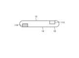
- FIG. 5 is a diagram showing an example of a PPG sensor according to an embodiment of the present disclosure.
- the PPG sensor includes a light source unit 111 (an example of a first sensor) that irradiates light onto a blood vessel BV, and a light receiving unit 112 (an example of a second sensor) that receives light scattered by the blood vessel.
- the PPG sensor includes a red light source unit 111_R that irradiates red light, and an infrared light source unit 111_I that irradiates infrared light.
- the light source unit 111 is disposed at one end 11 of the terminal device 10.
- the light receiving unit 112 is disposed at the other end 12 of the terminal device 10.
- the one end 11 and the other end 12 of the terminal device 10 are ends that face each other.
- the terminal device 10 is considered to be small because it is used by being inserted inside the body, such as under the skin.
- the terminal device 10 may have a cylindrical or flat shape. In this way, the shape of the terminal device 10, which is an implantable device, may be limited.
- the PPG sensor of the sensor unit 110 can suppress crosstalk between the light source unit 111 and the light receiving unit 112. This allows the PPG sensor of the sensor unit 110 to sense biometric information with higher accuracy.
- the ECG sensor is a sensor that detects the electrocardiogram of the user U_A.
- the ECG sensor detects the electrocardiogram of the user U_A via a plurality of electrodes.
- the ECG sensor detects a signal indicating the heartbeat from the potential difference between the plurality of electrodes.
- FIG. 6 is a diagram showing an example of an ECG sensor according to an embodiment of the present disclosure.
- the ECG sensor shown in FIG. 6 includes electrodes 113 and 114 (examples of a third sensor and a fourth sensor).
- the ECG sensor in FIG. 6 includes two electrodes 113 and 114, but the number of electrodes included in the ECG sensor is not limited to two and may be three or more.
- Electrode 113 is, for example, a potential electrode, and electrode 114 is a ground (GND) electrode.
- the ECG sensor detects the electrocardiogram of user U_A according to the potential difference between electrodes 113 and 114.
- the electrode 113 is disposed on the first surface 13 of the terminal device 10.
- the electrode 114 is disposed on the second surface 14 of the terminal device 10.
- the first surface 13 and the second surface 14 of the terminal device 10 face each other.
- the electrodes 113 and 114 are disposed on both ends of the terminal device 10, respectively.
- the ECG sensor can arrange the electrodes 113, 114 at a distance from each other. This allows the ECG sensor to further improve the detection accuracy of the electrocardiogram even if the shape of the terminal device 10 is restricted, for example, to a cylindrical or flat shape.
- the sensor unit 110 also includes a detection sensor that detects at least one of the insertion and removal of the terminal device 10.
- a detection sensor that detects at least one of the insertion and removal of the terminal device 10. Examples of the detection sensor include a capacitance sensor, an impedance sensor, a temperature sensor, a humidity sensor, a pressure sensor, an ultrasonic sensor, and a distortion sensor.
- the sensor unit 110 outputs the sensing results (the sensing results of the bioinformation sensor and the sensing results of the detection sensor) to the control unit 160.
- the communication unit 120 is a wireless communication processing unit that communicates with the communication device 20.
- the communication unit 120 may operate by receiving power supply from the communication device 20 (passive type), or may operate by receiving power supply from the battery unit 130 (active type).
- the communication unit 120 may have a circuit such as a rectifier.
- the communication unit 120 includes an antenna 121.
- the communication unit 120 can perform short-range wireless communication, such as NFC (Near Field Communication) or Bluetooth (registered trademark).
- short-range wireless communication such as NFC (Near Field Communication) or Bluetooth (registered trademark).
- Bluetooth registered trademark
- each component of the communication unit 120 may be configured separately for each wireless access method.
- the battery unit 130 supplies power to each unit of the terminal device 10.
- the battery unit 130 charges or discharges according to the control of the power supply management unit 140.
- the terminal device 10 only needs to have a power supply for driving itself, and may be provided with a capacitor or the like instead of the battery unit 130.
- the power supply management unit 140 manages charging to the battery unit 130 or discharging from the battery unit 130. For example, when the power supply management unit 140 receives power from an external device (not shown) via the antenna 141, The power is used to charge the battery unit 130. The power management unit 140 also supplies the power of the battery unit 130 to each unit of the terminal device 10.
- FIG. 4 shows a case where the antenna 121 for communication and the antenna 141 for wireless charging are different, the terminal device 10 may be configured to perform both communication and wireless charging using a single antenna.
- the storage unit 150 is a data readable/writable storage device such as a dynamic random access memory (DRAM), a static random access memory (SRAM), a flash memory, etc.
- the storage unit 150 stores, for example, the sensing result by the sensor unit 110, etc.
- the control unit 160 is a controller that controls each unit of the terminal device 10.
- the control unit 160 may be realized by a processor such as a central processing unit (CPU) or a micro processing unit (MPU).
- the control unit 160 may be realized by the processor executing various programs stored in a storage device inside the terminal device 10 using a random access memory (RAM) or the like as a working area.
- RAM random access memory
- the control unit 160 may be realized by an integrated circuit such as an ASIC (Application Specific Integrated Circuit) or an FPGA (Field Programmable Gate Array).
- the control unit 160 may also be realized by a GPU (Graphics Processing Unit).
- a CPU, an MPU, an ASIC, an FPGA, and a GPU can all be considered as controllers.
- the control unit 160 may be composed of multiple physically separated objects.
- the control unit 160 may be composed of multiple semiconductor chips.
- the control unit 160 includes a sensor control unit 161, a detection unit 162, an ID authentication unit 163, a communication control unit 164, a stop processing unit 165, an identity authentication unit 166, a restart processing unit 167, and a management unit 168.
- Each block constituting the control unit 160 is a functional block that indicates the function of the control unit 160.
- These functional blocks may be software blocks or hardware blocks.
- each of the above-mentioned functional blocks may be a single software module realized by software (including a microprogram), or a single circuit block on a semiconductor chip (die).
- each functional block may be a single processor or a single integrated circuit.
- the control unit 160 may be configured with functional units different from the above-mentioned functional blocks. The method of configuring the functional blocks is arbitrary.
- the sensor control unit 161 controls the sensor unit 110 to acquire the sensing result. For example, when the insertion detection condition is satisfied after the terminal device 10 receives the management setting from the communication device 20, the sensor control unit 161 controls, for example, the detection sensor of the sensor unit 110 to acquire the sensing result. The sensor control unit 161 outputs the acquired sensing result to the detection unit 162.
- the sensor control unit 161 controls the biometric sensor of the sensor unit 110 at a predetermined cycle to obtain sensing results.
- the sensor control unit 161 stores the obtained sensing results in the storage unit 150.
- ID authentication unit 163 performs authentication processing with the communication device 20 prior to communication processing using the communication unit 120.
- the ID authentication unit 163 performs authentication processing with the communication unit 120 using public key cryptography.
- the ID authentication unit 163 may execute authentication processing with the communication device 20 using identification information (device ID) of the terminal device 10 stored in advance. An example of the authentication processing will be described later with reference to FIG. 8.
- the ID authentication unit 163 obtains the result of the authentication process (authentication success/failure) from the communication device 20 and outputs it to the communication control unit 164.
- Non-returnable stop processing An example of the non-returnable stop process is a process of stopping the authentication process by software.
- the stop processing unit 165 deletes programs that operate the terminal device 10, such as programs related to the authentication process and programs for communication processing.
- the stop processing unit 165 may delete data used to control the terminal device 10, such as data used for the authentication process, such as identification information of the terminal device 10, and data used for communication processing.
- the stop processing unit 165 can also use hardware logic to move the state machine to a state to which it cannot transition, thereby disabling subsequent operations (e.g., authentication processing, communication processing, and other operations).
- the stop processing unit 165 can also stop the authentication process in a hardware manner by writing a Disable flag to the OneTimePROM, thereby preventing the OneTimePROM from being modified thereafter.
- Methods for writing the Disable flag include, for example, burning off the wiring with a high voltage and destroying the insulating film.
- the stop processing unit 165 executes the non-returnable stop processing, so that once the terminal device 10 is removed from the body, it cannot be reused. Since the terminal device 10 is inserted into the body for use, the number of times it can be used may be limited to one time for hygienic reasons.
- the terminal device 10 By constructing the housing of the terminal device 10 using a sterilizable material such as glass, the terminal device 10 may be inserted into the body of the user U_A and used again. In such a case, the stop processing unit 165 performs a returnable stop process.
- the state of the terminal device 10 may be completely reset so that the terminal device 10 can be inserted and used by a user U_B different from the user U_A.
- processing for reuse e.g., sterilization processing, reset processing, etc.
- the stop processing unit 165 also prevents personal information about the user U_A stored in the storage unit 150 from being read out from the storage unit 150. Examples of personal information include the sensing results of the sensor unit 110, and communication history with the communication device 20, such as payment history.
- the stop processing unit 165 executes an authentication stop process, etc., thereby further strengthening the security of the terminal device 10.
- the personal authentication unit 166 executes personal authentication processing to authenticate that the insertion destination of the terminal device 10 is the user U_A.
- the personal authentication unit 166 executes personal authentication processing when the detection unit 162 detects the insertion of the terminal device 10.
- the personal authentication unit 166 may execute personal authentication processing when the authentication processing is executed by the ID authentication unit 163.
- the identity authentication unit 166 performs identity authentication processing by comparing identification information for identifying the individual (hereinafter also referred to as identity information or identity ID) with the determination information.
- the personal information may be information determined in advance by the user U_A, such as a password, or characteristic information of the user U_A.
- the characteristic information of the user U_A may include, for example, information regarding a feature extracted from the biometric information of the user U_A.
- the personal information may be information specifying a specific environmental state.
- the characteristic information of the user U_A may be obtained from the communication device 20, or may be generated by the identity authentication unit 166 based on the sensing results of the sensor unit 110.
- the identity authentication unit 166 acquires determination information for performing identity authentication processing from the communication device 20. Alternatively, the identity authentication unit 166 may acquire the determination information by generating the determination information according to the sensing result by the sensor unit 110.
- the identity authentication unit 166 obtains the password from the communication device 20 as the determination information.
- the identity information is assumed to be characteristic information extracted from biometric information (e.g., fingerprint, iris, face, etc.) using a sensor in the communication device 20.
- the identity authentication unit 166 obtains the biometric information of the user U_A, or information extracted from this biometric information, from the communication device 20 as determination information.
- the terminal device 10 can further improve the security of the personal authentication process.
- the identity information is characteristic information generated by the identity authentication unit 166 based on biometric information (pulse, heart rate, blood pressure, blood glucose, etc.) that is the sensing result by the sensor unit 110.
- biometric information pulse, heart rate, blood pressure, blood glucose, etc.
- the identity authentication unit 166 acquires the sensing result from the sensor unit 110 and generates determination information (characteristic information) from the sensing result.
- the pulse rate and heart rate can be acquired, for example, from a PPG or ECG sensor.
- the blood pressure can be acquired from a pressure sensor or a blood flow rate sensor.
- the blood glucose can be acquired from a sensor that can check bodily fluids.
- the identity authentication unit 166 can perform identity authentication processing without communicating with an external device (e.g., communication device 20). This allows the identity authentication unit 166 to better prevent information leakage during biometric authentication.
- the terminal device 10 may obtain the personal information from the communication device 20.
- the terminal device 10 obtains the generated information obtained by the communication device 20 or an external device, or the feature information extracted from the generated information, as personal information via the communication device 20.
- the identity authentication unit 166 does not need to generate identity information from the sensing results of the sensor unit 110. Therefore, identity authentication processing can be performed even when the identity authentication unit 166 cannot generate identity information, such as when the terminal device 10 is inserted into the body for the first time.
- the identity authentication unit 166 compares the identity information and the judgment information, this comparison may also be performed by an external device (e.g., communication device 20).
- communication device 20 holds identity information in advance and performs the comparison based on the judgment information acquired from user U_A.
- the identity authentication unit 166 may acquire the comparison result from communication device 20 and perform identity authentication based on this comparison result. In this way, at least a part of the identity authentication process may be executed by an external device (e.g., communication device 20).
- the identity information is assumed to be information that specifies a specific environmental state (information regarding the electromagnetic field, temperature, pressure, etc.).
- the identity authentication unit 166 generates determination information based on the sensing results obtained from the sensor unit 110.
- the specific environmental state can be set using a special jig, for example. In this way, the user U_A can perform identity authentication using a dedicated device.
- restart processing unit 167 executes an authentication restart process to restart the authentication process depending on the result of the personal authentication by the personal authentication unit 166.
- restart processing unit 167 when the restart processing unit 167 receives an instruction to execute restart processing from the communication device 20 (an example of an external device), it executes authentication restart processing to restart the authentication processing according to the result of the identity authentication by the identity authentication unit 166.
- the resumption processing unit 167 executes processing to restore the restricted functions.
- the restart processing unit 167 executes an authentication restart process to restart the authentication process, assuming that the correct user U_A has been reinserted. If the personal authentication is unsuccessful, the restart processing unit 167 does not execute the authentication restart process. Alternatively, if the personal authentication is unsuccessful, the restart processing unit 167 may request the stop processing unit 165 to execute an unreturnable stop process, assuming that the device has been inserted by an unauthorized user U_B.
- the restart processing unit 167 notifies the power management unit 140 to supply power to the control unit 160 and the communication unit 120, for example. Alternatively, the restart processing unit 167 notifies the storage unit 150 to permit reading.
- the management unit 168 manages the operation of the control unit 160. For example, the management unit 168 switches between the authentication stop processing performed by the stop processing unit 165 being a restorable stop processing or a non-returnable stop processing according to a predetermined condition. For example, the management unit 168 switches between the restorable stop processing and the non-returnable stop processing according to an instruction from the communication device 20, the usage time of the terminal device 10, the number of times of use, the purpose, and the like.
- the management unit 168 may also execute a reset process to reset the terminal device 10.
- This reset process may be performed simultaneously with the unrecoverable stop process, or may be performed separately from the unrecoverable stop process.
- the reset process includes a process for deleting the identification information, personal information, and other information of the terminal device 10.
- the reset process may include a process for deleting programs executed by the terminal device 10.
- the management unit 168 executes the reset process according to instructions from the communication device 20. At this time, the management unit 168 may request the communication device 20 to perform authentication for executing the reset process, such as inputting a password.
- This password may be a master password of a user with administrator privileges.
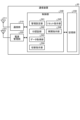
- the communication device 20 (an example of another device) is an information processing device that communicates with the terminal device 10.
- the communication device 20 may be an RFID tag reader, a mobile terminal such as a smartphone or a tablet terminal, a PC, or the like.
- the communication device 20 in FIG. 7 includes a communication unit 210, a power management unit 220, a memory unit 230, and a control unit 240.
- the communication unit 210 is a wireless communication processing unit that communicates with the terminal device 10.
- the communication unit 210 includes an antenna 211.
- the communication unit 210 can perform short-range wireless communication such as Near Field Communication (NFC) or Bluetooth (registered trademark).
- NFC Near Field Communication
- Bluetooth registered trademark
- the power management unit 220 supplies power to the terminal device 10.
- the power management unit 220 transmits power for charging the battery unit 130 of the terminal device 10 via the antenna 221.
- FIG. 7 shows a case where the antenna 211 for communication and the antenna 221 for wireless charging are different, the communication device 20 may perform both communication and wireless charging using a single antenna.
- the storage unit 230 is a data readable/writable storage device such as a DRAM, an SRAM, a flash memory, a hard disk, etc.
- the storage unit 230 stores, for example, the sensing results acquired from the terminal device 10.
- the control unit 240 is a controller that controls each unit of the communication device 20.
- the control unit 240 may be realized by a processor such as a CPU or an MPU.
- the control unit 240 may be realized by the processor executing various programs stored in a storage device inside the communication device 20 using a RAM (Random Access Memory) or the like as a working area.
- RAM Random Access Memory
- Each block constituting the control unit 240 (management setting unit 241 to restart instruction unit 246) is a functional block that indicates the function of the control unit 240.
- These functional blocks may be software blocks or hardware blocks.
- each of the above-mentioned functional blocks may be a single software module realized by software (including a microprogram), or a single circuit block on a semiconductor chip (die).
- each functional block may be a single processor or a single integrated circuit.
- the control unit 160 may be configured with functional units different from the above-mentioned functional blocks. The method of configuring the functional blocks is arbitrary.
- the management setting unit 241 sets the terminal device 10 by transmitting the management setting to the terminal device 10.
- the management setting unit 241 transmits the management setting before the terminal device 10 is inserted into the body of the user U_A. This performs initial settings of the terminal device 10.
- the management settings may include, for example, information for pairing with the terminal device 10 and personal information such as a password.
- pairing processing is performed between the terminal device 10 and the communication device 20, and personal information is set, if necessary.
- ID authentication unit 242 The ID authentication unit 242 authenticates whether or not the terminal device 10 is a valid communication partner prior to communication processing using the communication unit 210.
- the ID authentication unit 242 executes authentication processing with the terminal device 10 using, for example, identification information (device ID) of the terminal device 10 stored in advance.
- the transmission/reception unit 243 transmits and receives data to and from the terminal device 10 via the communication unit 210.
- the transmission/reception unit 243 for example, acquires a sensing result by the sensor unit 110 from the terminal device 10.
- the transmission/reception unit 243 also acquires data used in processing performed with the terminal device 10, such as information necessary for electronic payment.
- the transmission/reception unit 243 may also transmit information regarding the results of processing performed with the terminal device 10, such as balance information and payment history, to the terminal device 10. In this way, the transmission/reception unit 243 exchanges data with the terminal device 10.
- the switching instruction unit 244 instructs the terminal device 10 to switch between the restorable stop processing and the non-returnable stop processing.
- the switching instruction unit 244 switches between the restorable stop processing and the non-returnable stop processing depending on an instruction from the administrator or the user U_A, the usage time of the terminal device 10, the number of times of use, the purpose, and the like.
- the switching instruction unit 244 instructs the terminal device 10 to execute non-recoverable stop processing when, for example, the usage time exceeds a certain time or the number of times of usage exceeds a certain number.
- the switching instruction unit 244 also instructs the terminal device 10 to execute non-recoverable stop processing in the case of an experiment or trial, and to switch to non-recoverable stop processing in the case of actual use.
- the reset instruction unit 245 instructs the execution of a reset process to the terminal device 10.
- the reset instruction unit 245 notifies the execution of a reset process to the terminal device 10 in accordance with an instruction from, for example, an administrator or a user U_A.
- the restart instruction unit 246 instructs the terminal device 10 to execute the authentication restart process. For example, the restart instruction unit 246 sends an execution request for the authentication restart process to the terminal device 10 in accordance with an instruction from an administrator or a user U_A. Notify.
- Authentication process example> A description will be given of an authentication process that is executed prior to communication between the terminal device 10 and the communication device 20. The authentication process is executed in order for the terminal device 10 and the communication device 20 to communicate with each other.
- FIG. 8 is a sequence diagram showing an example of the flow of authentication processing according to an embodiment of the present disclosure. Here, an overview of authentication processing using public key cryptography is described.
- the communication device 20 generates a random number to be used in the authentication process (step S11).
- the communication device 20 transmits random number data including the generated random number to the terminal device 10 (step S12).
- the terminal device 10 that has received the random number data executes a signature process to generate signature data using the random number data and a private key (step S13).
- the private key is, for example, information related to the identification information (device ID) of the terminal device 10.
- the terminal device 10 for example, encrypts the random number data using the private key to generate signature data.
- the terminal device 10 transmits the generated signature data to the communication device 20 (step S14). Having received the signature data, the communication device 20 requests a certificate including public key information regarding the public key from the terminal device 10 (step S15).
- the terminal device 10 transmits a certificate including public key information to the communication device 20 (step S16). Having received the certificate, the communication device 20 verifies the signature data (step S17). For example, the communication device 20 decrypts the signature data using the public key information included in the certificate. For example, the communication device 20 verifies whether the terminal device 10 holds the assigned private key based on the decrypted data of the signature data.
- the communication device 20 determines that the authentication has been successful. On the other hand, if the terminal device 10 does not hold the assigned private key, in other words, if it is verified that the terminal device 10 is not a valid communication partner, the communication device 20 determines that the authentication has failed.
- the terminal device 10 determines whether the user U_A has inserted the card based on the result of the identity authentication process (step S105).
- step S105 If the personal authentication fails and it is determined that the card has not been inserted by user U_A, i.e., that the card has been inserted by a user U_B other than user U_A (step S105; No), the terminal device 10 proceeds to step S110.
- the terminal device 10 communicates with the communication device 20 (step S302).
- FIG. 12 is a flowchart showing an example of the flow of the sensing process according to an embodiment of the present disclosure.
- the sensing process in FIG. 12 is executed by the terminal device 10 at regular intervals, for example. Alternatively, the sensing process may be executed upon request from the communication device 20.
- the terminal device 10 executes the sensing process, for example, at regular intervals or based on a request from the communication device 20. This allows the terminal device 10 to perform sensing with low power consumption.
- the terminal device 10 determines whether the removal detection condition is satisfied (step S108).
- the removal detection condition is the elapsed time since the previous removal detection. For example, if a certain amount of time has elapsed since the previous removal detection, the terminal device 10 determines that the removal detection condition is satisfied.
- step S108 If the removal detection condition is not met (step S108; No), the terminal device 10 returns to step S108.
- step S108 determines whether or not removal from the body has been detected (step S109).
- the terminal device 10 determines whether or not the terminal device 10 itself has been removed from the body based on the sensing result by the sensor unit 110.
- step S109 If removal from the body is not detected (step S109; No), the terminal device 10 returns to step S108.
- step S109 if removal from the body is detected (step S109; Yes), the terminal device 10 stops the authentication function (step S110) and ends the process.
- the terminal device 10 stops the authentication function by executing a non-returnable stop process.
- the terminal device 10 detects removal from the body, for example, at regular intervals. This allows the terminal device 10 to further reduce power consumption due to removal from the body detection.
- FIG. 13 is a flowchart showing an example of the flow of the second process according to an embodiment of the present disclosure. Note that the process up to step S109 is the same as the first process shown in FIG. 12, and therefore a description thereof will be omitted.
- the terminal device 10 stops the authentication function (step S501).
- the terminal device 10 stops the authentication function by executing a return-enabled stop process.
- step S502 If a reset instruction is received (step S502; Yes), the terminal device 10 executes a reset process and resets its own settings (step S503).
- the terminal device 10 deletes, for example, the device ID, personal information, sensing results, etc. Note that, before executing the reset process, the terminal device 10 may request authentication for executing the reset process (for example, input of a master password, etc.) from the communication device 20.
- step S504 determines whether the restart condition is satisfied. For example, if the terminal device 10 detects its own insertion into the body, it determines that the restart condition is satisfied.
- step S504 If the restart condition is not met (step S504; No), the terminal device 10 returns to step S502.
- step S504 if the restart condition is met (step S504; Yes), the terminal device 10 executes the identity authentication process (step S505).
- the terminal device 10 executes the identity authentication process shown in FIG. 10.
- the terminal device 10 determines whether the user U_A has inserted the card based on the result of the identity authentication process (step S506).
- step S506 the terminal device 10 returns to step S502.
- the terminal device 10 may execute a non-returnable stop process and end the process.
- step S506 if the personal authentication is successful and it is determined that the user U_A inserted the card himself (step S506; Yes), the terminal device 10 executes the restart process (step S507) and returns to step S106.
- the terminal device 10 includes an ID authentication unit 163, a communication control unit 164, a detection unit 162, and a stop processing unit 165.
- the ID authentication unit 163 performs authentication using identification information (device ID) that identifies the terminal device 10. If authentication by the ID authentication unit 163 is successful, the communication control unit 164 communicates with the communication device 20.
- the detection unit 162 detects when the terminal device 10 inserted inside the body is removed from the body.
- the stop processing unit 165 stops authentication by the ID authentication unit 163 when removal from the body is detected.
- the authentication stop process when the terminal device 10 is removed from the body, the authentication stop process is executed, but the authentication stop process may not be executed even when the terminal device 10 is removed.
- the terminal device 10 when the terminal device 10 is removed according to a specified procedure, such as when a predetermined signal is received from the communication device 20 or when the terminal device 10 is removed under a specific environmental condition (electromagnetic field, temperature, pressure, etc.), the authentication stop process may not be executed.
- the terminal device 10 may also have a real-time clock.
- the terminal device 10 may record data such as an operation history in the storage unit 150 along with the time of the real-time clock, and may be configured so that past data cannot be deleted. This can further improve the security of the terminal device 10.
- the terminal device 10 periodically senses biometric information (sensing process), but the terminal device 10 may not sense biometric information for purposes other than personal authentication.
- the terminal device 10 may be used for processes that include interactions with the communication device 20, such as electronic payment and personal identification.
- each component of each device shown in the figure is a functional concept, and does not necessarily have to be physically configured as shown in the figure.
- the specific form of distribution and integration of each device is not limited to that shown in the figure, and all or part of them can be functionally or physically distributed and integrated in any unit depending on various loads, usage conditions, etc.
- the processing performed by each functional unit (power management unit 220, control unit 240) of the communication device 20 of the present disclosure may be performed by a dedicated device such as a charging device.
- the present technology can also be configured as follows. (1) an authentication unit that executes an authentication process for communicating with other devices; a communication unit that communicates with the other device when the authentication process is successful; A detection unit that detects removal of the device from the body; a stop processing unit that stops the authentication process by the authentication unit when the removal of the device from the body is detected; A terminal device comprising: (2) The terminal device according to (1), further comprising a restart processing unit that restarts the authentication process by the authentication unit after the authentication process is stopped. (3) The terminal device according to (2), wherein the restart processing unit restarts the authentication process in accordance with an instruction from an external device.
- restart processing unit restarts the authentication process when the instruction from the external device is at least one of input of a password and satisfaction of a specific environmental condition.
- the stop processing unit stops the authentication process by stopping at least one of communication by the communication unit and control by the control unit.
- the stop processing unit stops the authentication process so that the authentication process is not resumed.
- the stop processing unit stops the authentication process so that the authentication process is resumed or not resumed depending on a predetermined condition.
- the predetermined condition is at least one of the usage time, the number of usages, the purpose, and an instruction from the other device of the terminal device.
- the stop processing unit stops the authentication process by erasing at least one of a program and data.
- the stop processing unit stops the authentication process by destroying at least a part of a circuit.
- the stop processing unit stops the authentication processing by moving the state of a hardware logic that performs the authentication processing to a state to which a state machine cannot transition.
- the terminal device according to any one of (1) to (11), further comprising a wearing authentication unit that authenticates a wearer who wears the terminal device. (13) The terminal device according to (12), wherein the wearing authentication unit performs the authentication of the wearer using at least one of a password and biometric information of the wearer. (14) A sensing unit that senses the biological information of the wearer is further provided, The wearing authentication unit performs the authentication of the wearer using sensing information sensed in advance and the biometric information sensed by the sensing unit. A terminal device as described in (13).
- the terminal device 15) The terminal device according to (13) or (14), wherein the wearing authentication unit performs the authentication of the wearer when the detection unit detects the insertion for the first time and/or when the detection unit detects the insertion after the stop processing unit stops the authentication.
- the detection unit detects the insertion after a certain operation is performed on the terminal device, after a certain period of time has elapsed, and in response to at least one of the movement of the terminal device.
- Further comprising a sensor unit that senses biological information of a wearer who wears the terminal device The terminal device according to any one of (1) to (16), wherein the sensor unit senses the biological information at a predetermined period.
- Terminal device 20 Communication device 110 Sensor unit 120, 210 Communication unit 121, 141, 211, 221 Antenna 130 Battery unit 140, 220 Power supply management unit 150, 230 Storage unit 160, 240 Control unit 161 Sensor control unit 162 Detection unit 164 Communication control unit 165 Stop processing unit 166 Personal authentication unit 167 Restart processing unit 168 Management unit 241 Management setting unit 243 Transmission/reception unit 244 Switching instruction unit 245 Reset instruction unit 246 Restart instruction unit
Landscapes
- Engineering & Computer Science (AREA)
- Computer Security & Cryptography (AREA)
- Theoretical Computer Science (AREA)
- Health & Medical Sciences (AREA)
- Life Sciences & Earth Sciences (AREA)
- Physics & Mathematics (AREA)
- Computer Hardware Design (AREA)
- General Engineering & Computer Science (AREA)
- Software Systems (AREA)
- General Physics & Mathematics (AREA)
- Molecular Biology (AREA)
- Heart & Thoracic Surgery (AREA)
- Cardiology (AREA)
- Veterinary Medicine (AREA)
- Public Health (AREA)
- Computer Networks & Wireless Communication (AREA)
- Biophysics (AREA)
- Pathology (AREA)
- Biomedical Technology (AREA)
- Signal Processing (AREA)
- Medical Informatics (AREA)
- General Health & Medical Sciences (AREA)
- Surgery (AREA)
- Animal Behavior & Ethology (AREA)
- Computing Systems (AREA)
- Physiology (AREA)
- Vascular Medicine (AREA)
- Telephone Function (AREA)
Abstract
Description
<1.1.課題>
上述したように、体内に挿入されたマイクロチップを用いて、個人識別や電子決済等を行う技術がある。このマイクロチップを本人の体内から抜き出し、例えば、他人の体内に再挿入することで、不正が行われる恐れがある。
そこで、本開示の提案技術に係る端末装置は、自身が体内に挿入されたこと、及び、体内から抜き出されたことを検出し、体内から抜き出された場合は、自身が使用されないようにする。例えば、端末装置は、通信装置と通信を行うための認証処理を行う場合、この認証処理を行えないようにすることで、端末装置自身を使用できない状態とする。
<2.1.端末装置の構成例>
図4は、本開示の実施形態に係る端末装置10の機能構成例を示すブロック図である。なお、図4は、端末装置10の機能を概念的に示すものであり、実施形態によって様々な態様をとりうる。
センサ部110は、端末装置10の周囲の状態をセンシングする。センサ部110は、制御部160からの制御に従ってセンシングを行う。
PPGセンサは、ユーザU_Aの脈波信号を検出する生体情報センサである。ここで、脈波信号は、心臓の筋肉が一定のリズムで収縮すること(拍動、なお、単位時間の心臓における拍動回数を心拍数と呼ぶ)により、動脈を通じ全身に血液が送られて、動脈内壁に圧力の変化が生じ、体表面等に現れる動脈の拍動による波形のことである。
ECGセンサは、ユーザU_Aの心電図を検出するセンサである。ECGセンサは、複数の電極を介してユーザU_Aの心電図を検出する。ECGセンサは、複数の電極の電位差によって心拍を示す信号を検出する。
通信部120は、通信装置20と通信を行う無線通信処理部である。通信部120は、通信装置20から電力供給を受けて動作してもよく(パッシブタイプ)、あるいは、バッテリー部130から電力供給を受けて動作してもよい(アクティブタイプ)。通信部120は、例えば整流器等の回路を有しうる。
バッテリー部130は、端末装置10の各部に電力を供給する。バッテリー部130は、電源管理部140の制御に従って、充電又は放電を行う。なお、端末装置10は、自身が駆動するための電源を備えていればよく、バッテリー部130の代わりにコンデンサ等を備えていてもよい。
電源管理部140は、バッテリー部130への充電又はバッテリー部130からの放電を管理する。例えば、電源管理部140は、アンテナ141を介して外部装置(図示省略)から電力の供給を受けると、当該電力を用いてバッテリー部130を充電する。また、電源管理部140は、バッテリー部130の電力を端末装置10の各部に供給する。
記憶部150は、DRAM(Dynamic Random Access Memory)、SRAM(Static Random Access Memory)、フラッシュメモリ等のデータ読み書き可能な記憶装置である。記憶部150は、例えば、センサ部110によるセンシング結果等を記憶する。
制御部160は、端末装置10の各部を制御するコントローラ(controller)である。制御部160は、例えば、CPU(Central Processing Unit)またはMPU(Micro Processing Unit)等のプロセッサによって実現されてもよい。詳細には、制御部160は、端末装置10の内部の記憶装置に記憶されている各種プログラムを、プロセッサがRAM(Random Access Memory)等を作業領域として実行することによって実現されてもよい。
センサ制御部161は、センサ部110を制御してセンシング結果を取得する。例えば、センサ制御部161は、端末装置10が通信装置20から管理設定を受信した後に、挿入検出条件を満たす場合、例えば、センサ部110の検出センサを制御して、センシング結果を取得する。センサ制御部161は、取得したセンシング結果を検出部162に出力する。
検出部162は、センサ部110のセンシング結果に応じて、端末装置10の体内への挿入、及び、体外への抜出の少なくとも一方を検出する。例えば、センサ部110の温度センサのセンシング結果を用いる場合、検出部162は、温度センサが検出した温度(体温/環境温度)の変化に応じて、挿入/抜出を検出する。このように、検出部162は、センサ部110のセンシング結果の変化に応じて挿入/抜出を検出する。
ID認証部163は、通信部120を用いた通信処理に先立って、通信装置20との間で認証処理を行う。ID認証部163は、例えば、公開鍵暗号技術を用いた認証処理を通信部120との間で行う。あるいは、ID認証部163は、予め記憶する端末装置10の識別情報(装置ID)を用いて通信装置20との間で認証処理を実行してもよい。認証処理の一例については、図8を用いて後述する。
通信制御部164は、例えば、通信部120を制御して無線通信を行う。通信制御部164は、例えば、ID認証部163による認証処理の結果、認証に成功した場合、通信相手(例えば通信装置20)と通信を行う。
停止処理部165は、検出部162が端末装置10の抜出を検出した場合、認証停止処理を実行する。上述したように、認証停止処理には、端末装置10の機能を復帰させることができる復帰可停止処理と、端末装置10の機能の復帰ができない(認証の再開ができない)復帰不可停止処理とがある。
復帰可停止処理の一例として、制御部160の動作停止が挙げられる。例えば、停止処理部165は、電源管理部140に対して、制御部160への電力供給を停止させる。あるいは、停止処理部165は、制御部160に対して動作停止を指示する。なお、停止処理部165は、復帰に使用する制御部160の一部の機能(後述する検出部162、本人認証部166及び再開処理部167)が停止しないようにしてもよい。
復帰不可停止処理の一例として、ソフトウェア的に認証処理を停止させる処理が挙げられる。ソフトウェア的に認証処理を停止させるために、停止処理部165は、例えば、認証処理に関するプログラムや通信処理のプログラムなどの端末装置10を動作させるプログラムを削除する。あるいは、停止処理部165は、端末装置10の識別情報など認証処理に使用するデータや通信処理に使用するデータなどの端末装置10をどうさせるために使用するデータを削除してもよい。
本人認証部166(装着認証部の一例)は、端末装置10の挿入先がユーザU_Aであることを認証する本人認証処理を実行する。本人認証部166は、検出部162が端末装置10の挿入を検出した場合に、本人認証処理を実行する。あるいは、本人認証部166は、ID認証部163による認証処理が実行された場合に、本人認証処理を実行するようにしてもよい。
再開処理部167は、認証処理が停止されている状態で、検出部162が端末装置10の挿入を検出した場合に、本人認証部166による本人認証の結果に応じて認証処理を再開させる認証再開処理を実行する。
管理部168は、制御部160の動作を管理する。例えば、管理部168は、所定の条件に応じて、停止処理部165が行う認証停止処理が、復帰可停止処理であるか復帰不可停止処理であるかを切り替える。例えば、管理部168は、通信装置20からの指示、端末装置10の使用時間、使用回数、用途等に応じて復帰可停止処理及び復帰不可停止処理を切り替える。
通信装置20(他の装置の一例)は、端末装置10と通信を行う情報処理装置である。通信装置20は、RFIDタグの読み取り装置であってもよく、スマートフォンやタブレット端末などの携帯端末、PC等であってもよい。
通信部210は、端末装置10と通信を行う無線通信処理部である。通信部210は、アンテナ211を備える。通信部210は、例えば、NFC(Near Field Communication)やBluetooth(登録商標)等の近距離無線通信を行いうる。通信部210が複数の無線アクセス方式に対応する場合には、通信部210を構成する各部は、無線アクセス方式毎に個別に構成されてもよい。
電源管理部220は、端末装置10に電力を供給する。電源管理部220は、端末装置10のバッテリー部130を充電するための電力をアンテナ221を介して送信する。
記憶部230は、DRAM、SRAM、フラッシュメモリ、ハードディスク等のデータ読み書き可能な記憶装置である。記憶部230は、例えば、端末装置10から取得したセンシング結果等を記憶する。
制御部240は、通信装置20の各部を制御するコントローラ(controller)である。制御部240は、例えば、CPUまたはMPU等のプロセッサによって実現されてもよい。詳細には、制御部240は、通信装置20の内部の記憶装置に記憶されている各種プログラムを、プロセッサがRAM(Random Access Memory)等を作業領域として実行することによって実現されてもよい。
管理設定部241は、端末装置10に管理設定を送信することで、端末装置10の設定を行う。管理設定部241は、端末装置10がユーザU_Aの体内に挿入される前に管理設定を送信することで、端末装置10の初期設定を行う。管理設定は、例えば、端末装置10とのペアリングを行うための情報やパスワード等の本人情報を含みうる。
ID認証部242は、通信部210を用いた通信処理に先立って、端末装置10が正しい通信相手であるか否かの認証を行う。ID認証部242は、例えば、予め記憶する端末装置10の識別情報(装置ID)を用いて端末装置10との間で認証処理を実行する。
送受信部243は、通信部210を介して端末装置10トの間でデータの送受信を行う。送受信部243は、例えば、端末装置10からセンサ部110によるセンシング結果を取得する。また、送受信部243は、例えば、電子決済に必要な情報など、端末装置10との間で行われる処理に用いられるデータを取得する。
切替指示部244は、復帰可停止処理及び復帰不可停止処理の切り替えを端末装置10に指示する。切替指示部244は、管理者又はユーザU_Aからの指示、端末装置10の使用時間、使用回数、用途等に応じて復帰可停止処理及び復帰不可停止処理を切り替える。
リセット指示部245は、端末装置10に対してリセット処理の実行を指示する。リセット指示部245は、例えば管理者やユーザU_Aからの指示に従って、リセット処理の実行を端末装置10に通知する。
再開指示部246は、端末装置10に対して、認証再開処理の実行を指示する。再開指示部246は、例えば、管理者やユーザU_Aからの指示に従い、認証再開処理の実行要求を端末装置10に通知する。
<3.1.認証処理例>
端末装置10と通信装置20とが通信を行う際に、この通信に先立って実行される認証処理について説明する。認証処理は、端末装置10と通信装置20とが通信を行うために実行される。
認証停止処理が復帰不可停止処理である場合に端末装置10によって実行される第1の処理について説明する。
次に、認証停止処理が復帰可停止処理である場合に、端末装置10によって実行される第2の処理について説明する。
上述した実施形態に係る処理は、上記実施形態以外にも種々の異なる形態にて実施されてよい。
なお、本技術は以下のような構成も取ることができる。
(1)
他の装置との通信を行うための認証処理を実行する認証部と、
前記認証処理に成功した場合に前記他の装置と通信を行う通信部と、
体内へ挿入された自装置の体外への抜出を検出する検出部と、
前記体外への前記抜出が検出された場合に、前記認証部による前記認証処理を停止させる停止処理部と、
を備える端末装置。
(2)
前記認証処理が停止された後に、前記認証部による前記認証処理を再開させる再開処理部をさらに備える、(1)に記載の端末装置。
(3)
前記再開処理部は、外部装置からの指示に従って、前記認証処理を再開させる、(2)に記載の端末装置。
(4)
前記再開処理部は、パスワードが入力されたこと、及び、特定の環境条件が満たされたことの少なくとも一方を前記外部装置からの前記指示として、前記認証処理を再開させる、(3)に記載の端末装置。
(5)
前記停止処理部は、前記通信部による通信、及び、制御部による制御の少なくとも一方を停止させることで前記認証処理を停止させる、(1)~(4)のいずれか1つに記載の端末装置。
(6)
前記停止処理部は、前記認証処理が再開されないように、前記認証処理を停止させる、(1)~(5)のいずれか1つに記載の端末装置。
(7)
前記停止処理部は、所定の条件に応じて、前記認証処理が再開されるように、又は、再開されないように、前記認証処理を停止させる、(6)に記載の端末装置。
(8)
前記所定の条件は、前記端末装置の使用時間、使用回数、用途、及び、前記他の装置からの指示の少なくとも1つである、(7)に記載の端末装置。
(9)
前記停止処理部は、プログラム及びデータの少なくとも一方を消去することで前記認証処理を停止させる、(6)~(8)のいずれか1つに記載の端末装置。
(10)
前記停止処理部は、回路の少なくとも一部を破壊することで前記認証処理を停止させる、(6)~(9)のいずれか1つに記載の端末装置。
(11)
前記停止処理部は、前記認証処理を行うハードウェアロジックのステートを、ステートマシンの遷移できないステートに移動させることで、前記認証処理を停止させる、(6)~(10)のいずれか1つに記載の端末装置。
(12)
前記端末装置を装着する装着者の認証を行う装着認証部をさらに備える、(1)~(11)のいずれか1つに記載の端末装置。
(13)
前記装着認証部は、パスワード及び前記装着者の生体情報の少なくとも一方を用いて前記装着者の前記認証を行う、(12)に記載の端末装置。
(14)
前記装着者の前記生体情報をセンシングするセンシング部をさらに備え、
前記装着認証部は、予めセンシングされたセンシング情報と、前記センシング部がセンシングした前記生体情報と、を用いて前記装着者の前記認証を行う、
(13)に記載の端末装置。
(15)
前記装着認証部は、前記検出部が初めて前記挿入を検出した場合、及び、前記停止処理部が前記認証を停止した後に前記検出部が前記挿入を検出した場合の少なくとも一方の場合に、前記装着者の前記認証を行う、(13)又は(14)に記載の端末装置。
(16)
前記検出部は、前記端末装置に対して所定の操作が行われた後、一定期間の経過、及び、前記端末装置の動きの少なくとも一方に応じて、前記挿入の検出を行う、(1)~(15)のいずれか1つに記載の端末装置。
(17)
前記端末装置を装着する装着者の生体情報をセンシングするセンサ部をさらに備え、
前記センサ部は、所定の周期で前記生体情報をセンシングする、(1)~(16)のいずれか1つに記載の端末装置。
(18)
第1のセンサ及び第2のセンサを用いて前記端末装置を装着する装着者の生体情報をセンシングするセンサ部をさらに備え、
前記第1のセンサは、前記端末装置の第1の端部に配置され、
前記第2のセンサは、前記端末装置の、前記第1の端部と対向する第2の端部に配置される、
(1)~(17)のいずれか1つに記載の端末装置。
(19)
第3のセンサ及び第4のセンサを用いて前記端末装置を装着する装着者の生体情報をセンシングするセンサ部をさらに備え、
前記第3のセンサは、前記端末装置の第1の面に配置され、
前記第4のセンサは、前記端末装置の、前記第1の面と対向する第2の面に配置される、
(1)~(18)のいずれか1つに記載の端末装置。
(20)
他の装置との通信を行うための認証処理を実行することと、
前記認証処理に成功した場合に前記他の装置と通信を行うことと、
体内へ挿入された自装置の体外への抜出を検出することと、
前記体外への前記抜出が検出された場合に、前記認証処理を停止させることと、
を含む方法。
20 通信装置
110 センサ部
120,210 通信部
121,141,211,221 アンテナ
130 バッテリー部
140,220 電源管理部
150,230 記憶部
160,240 制御部
161 センサ制御部
162 検出部
164 通信制御部
165 停止処理部
166 本人認証部
167 再開処理部
168 管理部
241 管理設定部
243 送受信部
244 切替指示部
245 リセット指示部
246 再開指示部
Claims (20)
- 他の装置との通信を行うための認証処理を実行する認証部と、
前記認証処理に成功した場合に前記他の装置と通信を行う通信部と、
体内へ挿入された自装置の体外への抜出を検出する検出部と、
前記体外への前記抜出が検出された場合に、前記認証部による前記認証処理を停止させる停止処理部と、
を備える端末装置。 - 前記認証処理が停止された後に、前記認証部による前記認証処理を再開させる再開処理部をさらに備える、請求項1に記載の端末装置。
- 前記再開処理部は、外部装置からの指示に従って、前記認証処理を再開させる、請求項2に記載の端末装置。
- 前記再開処理部は、パスワードが入力されたこと、及び、特定の環境条件が満たされたことの少なくとも一方を前記外部装置からの前記指示として、前記認証処理を再開させる、請求項3に記載の端末装置。
- 前記停止処理部は、前記通信部による通信、及び、制御部による制御の少なくとも一方を停止させることで前記認証処理を停止させる、請求項1に記載の端末装置。
- 前記停止処理部は、前記認証処理が再開されないように、前記認証処理を停止させる、請求項1に記載の端末装置。
- 前記停止処理部は、所定の条件に応じて、前記認証処理が再開されるように、又は、再開されないように、前記認証処理を停止させる、請求項6に記載の端末装置。
- 前記所定の条件は、前記端末装置の使用時間、使用回数、用途、及び、前記他の装置からの指示の少なくとも1つである、請求項7に記載の端末装置。
- 前記停止処理部は、プログラム及びデータの少なくとも一方を消去することで前記認証処理を停止させる、請求項6に記載の端末装置。
- 前記停止処理部は、回路の少なくとも一部を破壊することで前記認証処理を停止させる、請求項6に記載の端末装置。
- 前記停止処理部は、前記認証処理を行うハードウェアロジックのステートを、ステートマシンの遷移できないステートに移動させることで、前記認証処理を停止させる、請求項6に記載の端末装置。
- 前記端末装置を装着する装着者の認証を行う装着認証部をさらに備える、請求項1に記載の端末装置。
- 前記装着認証部は、パスワード及び前記装着者の生体情報の少なくとも一方を用いて前記装着者の前記認証を行う、請求項12に記載の端末装置。
- 前記装着者の前記生体情報をセンシングするセンシング部をさらに備え、
前記装着認証部は、予めセンシングされたセンシング情報と、前記センシング部がセンシングした前記生体情報と、を用いて前記装着者の前記認証を行う、
請求項13に記載の端末装置。 - 前記装着認証部は、前記検出部が初めて前記挿入を検出した場合、及び、前記停止処理部が前記認証を停止した後に前記検出部が前記挿入を検出した場合の少なくとも一方の場合に、前記装着者の前記認証を行う、請求項13に記載の端末装置。
- 前記検出部は、前記端末装置に対して所定の操作が行われた後、一定期間の経過、及び、前記端末装置の動きの少なくとも一方に応じて、前記挿入の検出を行う、請求項1に記載の端末装置。
- 前記端末装置を装着する装着者の生体情報をセンシングするセンサ部をさらに備え、
前記センサ部は、所定の周期で前記生体情報をセンシングする、請求項1に記載の端末装置。 - 第1のセンサ及び第2のセンサを用いて前記端末装置を装着する装着者の生体情報をセンシングするセンサ部をさらに備え、
前記第1のセンサは、前記端末装置の第1の端部に配置され、
前記第2のセンサは、前記端末装置の、前記第1の端部と対向する第2の端部に配置される、
請求項1に記載の端末装置。 - 第3のセンサ及び第4のセンサを用いて前記端末装置を装着する装着者の生体情報をセンシングするセンサ部をさらに備え、
前記第3のセンサは、前記端末装置の第1の面に配置され、
前記第4のセンサは、前記端末装置の、前記第1の面と対向する第2の面に配置される、
請求項1に記載の端末装置。 - 他の装置との通信を行うための認証処理を実行することと、
前記認証処理に成功した場合に前記他の装置と通信を行うことと、
体内へ挿入された自装置の体外への抜出を検出することと、
前記体外への前記抜出が検出された場合に、前記認証処理を停止させることと、
を含む方法。
Priority Applications (1)
| Application Number | Priority Date | Filing Date | Title |
|---|---|---|---|
| EP24823221.7A EP4730171A4 (en) | 2023-06-15 | 2024-05-28 | TERMINAL DEVICE AND METHOD |
Applications Claiming Priority (2)
| Application Number | Priority Date | Filing Date | Title |
|---|---|---|---|
| JP2023-098715 | 2023-06-15 | ||
| JP2023098715 | 2023-06-15 |
Publications (1)
| Publication Number | Publication Date |
|---|---|
| WO2024257601A1 true WO2024257601A1 (ja) | 2024-12-19 |
Family
ID=93851754
Family Applications (1)
| Application Number | Title | Priority Date | Filing Date |
|---|---|---|---|
| PCT/JP2024/019516 Ceased WO2024257601A1 (ja) | 2023-06-15 | 2024-05-28 | 端末装置及び方法 |
Country Status (2)
| Country | Link |
|---|---|
| EP (1) | EP4730171A4 (ja) |
| WO (1) | WO2024257601A1 (ja) |
Citations (11)
| Publication number | Priority date | Publication date | Assignee | Title |
|---|---|---|---|---|
| JP2002091883A (ja) * | 2000-09-20 | 2002-03-29 | Sanyo Electric Co Ltd | データ配信システムおよびデータ端末装置 |
| JP2003070063A (ja) * | 2001-08-24 | 2003-03-07 | Seiko Epson Corp | 無線通信端末装置のデータ保護装置、無線通信端末装置のデータ保護方法及びそのためのシステム |
| JP2014179105A (ja) | 2014-03-28 | 2014-09-25 | Yoshida Dental Mfg Co Ltd | 口腔内粘膜組織の外科的手術治療の過程で歯周組織内に埋設する無線通信媒体を使った移動体通信端末の制御方法 |
| US8966312B1 (en) * | 2006-02-09 | 2015-02-24 | Virsec Systems, Inc. | System and methods for run time detection and correction of memory corruption |
| WO2017029766A1 (ja) * | 2015-08-20 | 2017-02-23 | 株式会社日立製作所 | 情報処理回路 |
| JP2020171368A (ja) * | 2019-04-08 | 2020-10-22 | Phcホールディングス株式会社 | 人体装着型センサ装置、生体情報測定装置、生体情報測定システムおよび人体装着型センサ装置の制御方法 |
| JP2020181609A (ja) * | 2013-03-15 | 2020-11-05 | プロテウス デジタル ヘルス, インコーポレイテッド | 本人認証装置システムおよび方法 |
| JP2022502201A (ja) * | 2018-10-05 | 2022-01-11 | アライヴコア・インコーポレーテッド | モバイルデバイスを用いたユーザの健康状態の継続的監視 |
| JP2022512392A (ja) * | 2018-12-12 | 2022-02-03 | バイオトロニック エスエー アンド カンパニー カーゲー | Imd通信のための強化された認証 |
| JP2022522193A (ja) * | 2019-02-26 | 2022-04-14 | パーカシスト, インコーポレイテッド | 経皮的空気圧心臓補助のための装置、システム、および方法 |
| JP2023018683A (ja) | 2013-03-14 | 2023-02-08 | スティムウェイブ テクノロジーズ インコーポレイテッド | 無線植込み型電力受信機システム及び方法 |
Family Cites Families (2)
| Publication number | Priority date | Publication date | Assignee | Title |
|---|---|---|---|---|
| US8886316B1 (en) * | 2012-12-18 | 2014-11-11 | Emc Corporation | Authentication of external devices to implantable medical devices using biometric measurements |
| JP7532128B2 (ja) * | 2020-07-21 | 2024-08-13 | 株式会社東芝 | 認証装置 |
-
2024
- 2024-05-28 EP EP24823221.7A patent/EP4730171A4/en active Pending
- 2024-05-28 WO PCT/JP2024/019516 patent/WO2024257601A1/ja not_active Ceased
Patent Citations (11)
| Publication number | Priority date | Publication date | Assignee | Title |
|---|---|---|---|---|
| JP2002091883A (ja) * | 2000-09-20 | 2002-03-29 | Sanyo Electric Co Ltd | データ配信システムおよびデータ端末装置 |
| JP2003070063A (ja) * | 2001-08-24 | 2003-03-07 | Seiko Epson Corp | 無線通信端末装置のデータ保護装置、無線通信端末装置のデータ保護方法及びそのためのシステム |
| US8966312B1 (en) * | 2006-02-09 | 2015-02-24 | Virsec Systems, Inc. | System and methods for run time detection and correction of memory corruption |
| JP2023018683A (ja) | 2013-03-14 | 2023-02-08 | スティムウェイブ テクノロジーズ インコーポレイテッド | 無線植込み型電力受信機システム及び方法 |
| JP2020181609A (ja) * | 2013-03-15 | 2020-11-05 | プロテウス デジタル ヘルス, インコーポレイテッド | 本人認証装置システムおよび方法 |
| JP2014179105A (ja) | 2014-03-28 | 2014-09-25 | Yoshida Dental Mfg Co Ltd | 口腔内粘膜組織の外科的手術治療の過程で歯周組織内に埋設する無線通信媒体を使った移動体通信端末の制御方法 |
| WO2017029766A1 (ja) * | 2015-08-20 | 2017-02-23 | 株式会社日立製作所 | 情報処理回路 |
| JP2022502201A (ja) * | 2018-10-05 | 2022-01-11 | アライヴコア・インコーポレーテッド | モバイルデバイスを用いたユーザの健康状態の継続的監視 |
| JP2022512392A (ja) * | 2018-12-12 | 2022-02-03 | バイオトロニック エスエー アンド カンパニー カーゲー | Imd通信のための強化された認証 |
| JP2022522193A (ja) * | 2019-02-26 | 2022-04-14 | パーカシスト, インコーポレイテッド | 経皮的空気圧心臓補助のための装置、システム、および方法 |
| JP2020171368A (ja) * | 2019-04-08 | 2020-10-22 | Phcホールディングス株式会社 | 人体装着型センサ装置、生体情報測定装置、生体情報測定システムおよび人体装着型センサ装置の制御方法 |
Non-Patent Citations (1)
| Title |
|---|
| See also references of EP4730171A4 |
Also Published As
| Publication number | Publication date |
|---|---|
| EP4730171A1 (en) | 2026-04-22 |
| EP4730171A4 (en) | 2026-04-22 |
Similar Documents
| Publication | Publication Date | Title |
|---|---|---|
| US12061683B2 (en) | Methods for managing user access to computing devices based on evaluation of authentication and maintenance of user control | |
| JP4874956B2 (ja) | 電子パスポート用のスマートカード、電子パスポート、並びにスマートカード又は電子パスポートを所持している人物を認証するための方法、システム及び装置 | |
| CN108874271B (zh) | 包括多个输入设备的电子设备及其控制方法 | |
| US6778066B2 (en) | Personal identification badge that resets on the removal of the badge from the wearer | |
| US20100085160A1 (en) | Systems and Methods for Zero-Power Security | |
| CN110286944B (zh) | 用于在电子装置中处理生物计量信息的方法和设备 | |
| US8866760B2 (en) | User identification based on body-coupled communication | |
| US8899487B2 (en) | Biometric identity verification system and method | |
| JP7026701B2 (ja) | スマートカードおよびスマートカードの制御方法 | |
| JP6380995B2 (ja) | バイオメトリクスによる人物認証 | |
| US20190392436A1 (en) | Fingerprint recognition card and method for operating power source by using fingerprint recognition card | |
| JP2008073462A (ja) | 認証装置、及び認証方法 | |
| JP2019508825A (ja) | 生体特徴識別装置及び方法並びに生体特徴テンプレート登録方法 | |
| JP2022512392A (ja) | Imd通信のための強化された認証 | |
| US20240054196A1 (en) | Transparent authentication using biometric factors | |
| Hei et al. | Security for wireless implantable medical devices | |
| CN106446627A (zh) | 在电子终端进行身份验证的方法和设备 | |
| WO2024257601A1 (ja) | 端末装置及び方法 | |
| Cámara Nuñez et al. | Security and privacy issues in implantable medical devices: A comprehensive survey | |
| US12547711B2 (en) | Out-of-band pairing for wireless neural implant | |
| Núñez et al. | Cybersecurity in implantable medical devices | |
| KR20180082763A (ko) | 심전도 신호를 이용한 사용자 인증방법 | |
| KR20180082762A (ko) | 심전도 신호를 이용한 사용자 인증장치 | |
| KR20230026697A (ko) | 생체인식 기반의 태양광 충전식 otp 생성기 | |
| HK1110972A (en) | Smart card for passport, electronic passport, and method, system, and apparatus for authenticating person holding smart card or electronic passport |
Legal Events
| Date | Code | Title | Description |
|---|---|---|---|
| 121 | Ep: the epo has been informed by wipo that ep was designated in this application |
Ref document number: 24823221 Country of ref document: EP Kind code of ref document: A1 |
|
| WWE | Wipo information: entry into national phase |
Ref document number: 2024823221 Country of ref document: EP |
|
| NENP | Non-entry into the national phase |
Ref country code: DE |
|
| ENP | Entry into the national phase |
Ref document number: 2024823221 Country of ref document: EP Effective date: 20260115 |
|
| ENP | Entry into the national phase |
Ref document number: 2024823221 Country of ref document: EP Effective date: 20260115 |
|
| ENP | Entry into the national phase |
Ref document number: 2024823221 Country of ref document: EP Effective date: 20260115 |
|
| ENP | Entry into the national phase |
Ref document number: 2024823221 Country of ref document: EP Effective date: 20260115 |
|
| WWP | Wipo information: published in national office |
Ref document number: 2024823221 Country of ref document: EP |