WO2024257712A1 - Radiation treatment assistance device, radiation treatment assistance program, and radiation treatment system - Google Patents
Radiation treatment assistance device, radiation treatment assistance program, and radiation treatment system Download PDFInfo
- Publication number
- WO2024257712A1 WO2024257712A1 PCT/JP2024/020982 JP2024020982W WO2024257712A1 WO 2024257712 A1 WO2024257712 A1 WO 2024257712A1 JP 2024020982 W JP2024020982 W JP 2024020982W WO 2024257712 A1 WO2024257712 A1 WO 2024257712A1
- Authority
- WO
- WIPO (PCT)
- Prior art keywords
- image data
- magnetic resonance
- resonance image
- contour
- unit
- Prior art date
- Legal status (The legal status is an assumption and is not a legal conclusion. Google has not performed a legal analysis and makes no representation as to the accuracy of the status listed.)
- Ceased
Links
Images


Classifications
-
- A—HUMAN NECESSITIES
- A61—MEDICAL OR VETERINARY SCIENCE; HYGIENE
- A61B—DIAGNOSIS; SURGERY; IDENTIFICATION
- A61B5/00—Measuring for diagnostic purposes; Identification of persons
- A61B5/05—Detecting, measuring or recording for diagnosis by means of electric currents or magnetic fields; Measuring using microwaves or radio waves
- A61B5/055—Detecting, measuring or recording for diagnosis by means of electric currents or magnetic fields; Measuring using microwaves or radio waves involving electronic [EMR] or nuclear [NMR] magnetic resonance, e.g. magnetic resonance imaging
Definitions
- the present invention relates to a radiation therapy support device, a radiation therapy support program, and a radiation therapy system.
- Radiation therapy is one of the "three pillars of cancer treatment" and plays an important role in cancer treatment. In radiation therapy, it is important to understand the location of the targeted tumor.
- MRI Magnetic Resonance Imaging
- MR Magnetic Resonance Imaging
- X-ray CT X-ray CT
- a linac linear accelerator
- MR linacs can acquire MR images while irradiating the therapeutic radiation beam (during irradiation), making it possible to match the position of the tumor with the planned target volume to which the therapeutic radiation beam is irradiated.
- the spatial extent of the targeted tumor is defined in ICRU (International Commission on Radiation Units and Measurements) Report 83 (Non-Patent Document 1).
- Gross tumor volume is the volume in which the presence of a tumor can be confirmed with the naked eye. The location and size of the gross tumor volume are determined by imaging diagnostics such as endoscopy, X-ray CT scans, MR scans, and ultrasound scans.
- Planning target volume is the target volume that is determined taking into account the uncertainties of radiation therapy.
- MR image-guided immediate adaptive radiation therapy is a type of radiation therapy in which, with the patient positioned on the treatment bed, three-dimensional MR images are acquired on the day of treatment, and based on the images, contours are drawn, a new treatment plan is created, verified, and radiation is administered.
- MR image-guided immediate adaptive radiation therapy using an MR linac in order to confirm that radiation is being administered according to the treatment plan created immediately before treatment, it is important to directly observe the tumor being irradiated with the therapeutic radiation beam using MR images and to appropriately control the therapeutic radiation beam. Specifically, the macroscopic tumor volume is grasped using MR images, and the therapeutic radiation beam of the linac is controlled based on the planned target volume calculated using a treatment planning device.
- Patent Document 1 discloses a method for reconstructing MR images using a B-TFE (Balanced Turbo Field Echo) sequence, which is a high-speed imaging sequence.
- Patent document 2 discloses the configuration of an MR device combined with a linear accelerator.
- the system discloses a system for more quickly acquiring imaging slices by comparing information indicating a portion of a target trajectory that is rapidly acquired from one or more imaging slices with information acquired from a previously acquired volume reference image.
- the tumor which is the target of radiation irradiation, moves with breathing, heart movement, intestinal peristalsis, etc. This can result in the therapeutic radiation beam being significantly displaced from the planned target volume.
- the tumor position significantly shifts from the planned target volume into which the therapeutic radiation beam is to be irradiated, it is necessary to quickly stop the irradiation of the therapeutic radiation beam. This action prevents damage to areas other than the targeted tumor that would otherwise be caused by the irradiation of the therapeutic radiation beam. For this reason, it is important to check the tumor position in real time while the therapeutic radiation beam is being irradiated.
- the present invention was conceived in consideration of the above-mentioned problems, and its purpose is to provide a radiation therapy support device, a radiation therapy support program, and a radiation therapy system that can monitor in real time during irradiation of a therapeutic radiation beam to ensure that a tumor that moves due to breathing, cardiac movement, intestinal peristalsis, etc. remains within the planned target volume of the therapeutic radiation beam.
- the radiation therapy support device is a radiation therapy support device used for MR image-guided real-time adaptive radiation therapy, and includes a magnetic resonance image acquisition unit that acquires magnetic resonance image data of an area including a planned target volume to be irradiated with a therapeutic radiation beam, and an image synthesis unit that synthesizes preset contour image data with the magnetic resonance image data acquired by the magnetic resonance image acquisition unit, the magnetic resonance image acquisition unit acquires first magnetic resonance image data which is a magnetic resonance image when the therapeutic radiation beam is being irradiated, and second magnetic resonance image data which is a magnetic resonance image when the therapeutic radiation beam is not being irradiated, and the image synthesis unit synthesizes the contour image data including image data of the contour of the macroscopic tumor volume and image data of the contour of the planned target volume with the second magnetic resonance image data.
- the radiation therapy support device is the same as the first invention, but is characterized in that the second magnetic resonance image data has a longer update time than the first magnetic resonance image data.
- the radiation therapy support device is the first invention, characterized in that the contour image data includes image data of the contours of risk organs or image data of the contours of dose distribution.
- the radiation therapy support device is the same as the first invention, but is characterized in that the magnetic resonance image acquisition unit alternately switches between acquiring the first magnetic resonance image data and acquiring the second magnetic resonance image data.
- the radiation therapy support device is the first invention, characterized in that the contour image data includes image data in which a contour line is extracted using multi-value information of the image data of the macroscopic tumor volume.
- the radiation therapy support device is the first invention, further comprising a composite image selection unit that distributes or switches the second magnetic resonance image data and inputs it to the image synthesis unit.
- the radiation therapy support program according to the seventh invention is a radiation therapy support program used in MR image-guided real-time adaptive radiation therapy, and causes a computer to execute a magnetic resonance image acquisition function for acquiring magnetic resonance image data of an area including a planned target volume to be irradiated with a therapeutic radiation beam, and an image synthesis function for synthesizing preset contour image data with the magnetic resonance image data acquired by the magnetic resonance image acquisition function, the magnetic resonance image acquisition function acquiring first magnetic resonance image data which is a magnetic resonance image when the therapeutic radiation beam is being irradiated, and second magnetic resonance image data which is a magnetic resonance image when the therapeutic radiation beam is not being irradiated, and the image synthesis function synthesizes the contour image data including image data of the contour of the macroscopic tumor volume and image data of the contour of the planned target volume with the second magnetic resonance image data.
- the radiation therapy system is a radiation therapy system used for MR image-guided real-time adaptive radiation therapy, and includes a treatment planning unit that creates an irradiation plan including a planned target volume to be irradiated with a therapeutic radiation beam, an irradiation unit that irradiates the therapeutic radiation beam based on the irradiation plan created by the treatment planning unit, a magnetic resonance image acquisition unit that acquires magnetic resonance image data of an area including the planned target volume to be irradiated with the therapeutic radiation beam by the irradiation unit, and an image synthesis unit that synthesizes preset contour image data with the magnetic resonance image data acquired by the magnetic resonance image acquisition unit, wherein the magnetic resonance image acquisition unit acquires first magnetic resonance image data which is a magnetic resonance image when the therapeutic radiation beam is being irradiated and second magnetic resonance image data which is a magnetic resonance image when the therapeutic radiation beam is not being irradiated, and the image synthesis unit synthesizes the contour image data including image data of the
- the image synthesis unit synthesizes contour image data including image data of the contour of the macroscopic tumor volume and image data of the contour of the planned target volume with the second magnetic resonance image data. Therefore, an image can be obtained in which spatial resolution (including contrast resolution) is prioritized. This makes it possible to monitor in real time during irradiation of the therapeutic radiation beam whether a tumor that moves due to breathing, cardiac movement, intestinal peristalsis, etc. remains within the planned target volume of the therapeutic radiation beam.
- FIG. 1 is a diagram illustrating an example of a radiation therapy support apparatus.
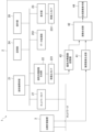
- FIG. 2 is a diagram illustrating an example of a radiation therapy system according to the first embodiment.
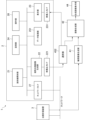
- FIG. 3 is a diagram illustrating an example of a radiation therapy system according to the second embodiment.
- FIG. 4 is a diagram illustrating an example of a radiation therapy system according to the third embodiment.
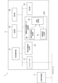
- FIG. 5 is a diagram illustrating an example of a radiation therapy system according to the fourth embodiment.
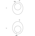
- 6(a) and 6(b) show respiratory-moving tumors during deep expiration.
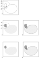
- 7(a)-7(e) show diagrams depicting tumor-bearing organs, organs at risk and planning target volumes.
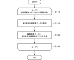
- FIG. 8 is a flowchart showing an example of the operation of the radiation therapy support program.
- the radiation therapy support device 100 is a device used for MR image-guided real-time adaptive radiation therapy.
- the radiation therapy support device 100 includes a magnetic resonance image acquisition unit 46 that acquires magnetic resonance image data of an area including at least one of a planned target volume to be irradiated with a therapeutic radiation beam or an area near the planned target volume, and an image synthesis unit 42 that synthesizes contour image data with the magnetic resonance image data.
- the magnetic resonance image data can be obtained by imaging a patient using an MR device. For example, in the case of a liver cancer patient, magnetic resonance image data is generated by imaging an area including a liver tumor.
- the radiation therapy support device 100 may include, for example, a contour image generation unit 41 that generates contour image data, or may include, for example, a synthetic image display unit 44.
- the magnetic resonance image data acquired by the magnetic resonance image acquisition unit 46 and the contour image data generated by the contour image generation unit 41 from the contour image original data are input to the image synthesis unit 42.
- the contour image original data is generated using, for example, a known treatment planning device.
- the image synthesis unit 42 may also acquire contour image data generated using, for example, a known treatment planning device, and the method of generating and acquiring the contour image data can be set arbitrarily depending on the application.
- the contour image data includes contour images of the macroscopic tumor volume, clinical target volume, planned target volume, organ volume near the target, organ at risk volume, or planned organ at risk volume.
- the magnetic resonance image acquisition unit 46 acquires first magnetic resonance image data, which is a magnetic resonance image when the therapeutic radiation beam is being irradiated, and second magnetic resonance image data, which is a magnetic resonance image when the therapeutic radiation beam is not being irradiated.
- the magnetic resonance image data acquired by the magnetic resonance image acquisition unit 46 is generated, for example, using a known MR linac system.
- the image synthesis unit 42 synthesizes contour image data including image data of the contour of the macroscopic tumor volume and image data of the contour of the planned target volume, which are preset with respect to the second magnetic resonance image data.
- image data obtained by synthesizing the contour image data including image data of the contour of the macroscopic tumor volume and image data of the contour of the planned target volume with respect to the second magnetic resonance image data will be referred to as contour synthesis image data.
- a publicly known image synthesis technique can be used as a method for synthesizing each image data.
- the contour composite image data composited by the image composition unit 42 is displayed on the composite image display unit 44.
- the composite image display unit 44 is, for example, the display of a notebook personal computer.
- the magnetic resonance image data obtained from the MR device is still image data or cine image (moving image) data.
- An MR linac which combines an MR device with a radiation therapy device, has the advantage of being able to acquire magnetic resonance image data while a therapeutic radiation beam is being irradiated.
- Magnetic resonance image data is image data captured, for example, by an MR device mounted on the MR linac.
- the MR linac can acquire magnetic resonance image data not only when a therapeutic radiation beam is not being irradiated, but also when a therapeutic radiation beam is being irradiated.
- the pixel intensity of magnetic resonance image data imaged using the high-speed imaging sequence B-TFE is proportional to the ratio of the transverse relaxation time to the longitudinal relaxation time, but for example, the ratio of relaxation times is almost the same for liver tumors and normal liver tissue. For this reason, it is often the case that there is no contrast between liver tumors and normal liver tissue. Therefore, it is difficult to monitor tumors, such as liver tumors that move due to respiration, in real time during irradiation of the therapeutic radiation beam.
- the radiation therapy support device 100 can display first magnetic resonance image data that prioritizes time resolution during irradiation of a therapeutic radiation beam, while displaying on the composite image display unit 44 contour composite image data that combines contour image data with second magnetic resonance image data that prioritizes spatial resolution captured when irradiation is not occurring.
- the B-TFE high-speed imaging sequence used for the first magnetic resonance image data can display about five images per second, making it possible to monitor the movement of the tumor in almost real time, but there has been a problem with insufficient contrast of the tumor.
- high-speed imaging sequences such as the T1-weighted high-speed imaging sequence or the T2-weighted high-speed imaging sequence used for the second magnetic resonance image data can display about one to three images per second, and although the display speed is inferior, it has the advantage of improving the contrast of the tumor.
- the second magnetic resonance image data can be acquired with a priority on spatial resolution.
- the second magnetic resonance image data with a priority on spatial resolution can be input to the magnetic resonance image acquisition unit 46.
- the second magnetic resonance image data with a priority on spatial resolution is, for example, a two-dimensional T1-weighted cine image or a two-dimensional T2-weighted cine image.
- the original contour image data is image data including image data of the macroscopic tumor volume and image data of the planned target volume.
- the contour image generating unit 41 When the original contour image data is input, the contour image generating unit 41 generates contour image data including image data of the contour of the macroscopic tumor volume and image data of the contour of the planned target volume. Note that the contour image generating unit 41 can generate contour image data including image data of the contour of the macroscopic tumor volume and image data of the contour of the planned target volume using known technology.
- the image synthesis unit 42 synthesizes the second magnetic resonance image data acquired by the magnetic resonance image acquisition unit 46 with the preset contour image data generated by the contour image generation unit 41.
- contour synthesis image data can be acquired that synthesizes an image in which the tumor is visible with priority given to spatial resolution and an image in which the contour image data is superimposed, and the synthesized image can be displayed on the synthetic image display unit 44.
- the radiation therapy support device 100 can acquire second magnetic resonance image data with a priority on spatial resolution, and synthesize contour image data with the second magnetic resonance image data. Therefore, it is possible to obtain contour synthetic image data in which contour image data is synthesized with the second magnetic resonance image data.
- the synthetic image display unit 44 can be checked during irradiation of the therapeutic radiation beam. This makes it possible to monitor in real time during irradiation of the therapeutic radiation beam that a tumor moving due to breathing, cardiac movement, intestinal peristalsis, etc. remains in the planned target volume of the therapeutic radiation beam.
- the contrast of the tumor by the T1-weighted fast imaging sequence or the T2-weighted fast imaging sequence depends on the tumor, so it is possible to alternately display images obtained by both sequences and select and use the sequence that gives better contrast.
- the tumor contour is within the range of respiratory movement, and the volume obtained by adding an irradiation margin (for example, 3 mm to 5 mm) to this tumor contour becomes the planned target volume.
- the planning target volume can be defined by adding an irradiation margin to the contour of the tumor that does not move due to respiration.
- the second magnetic resonance image data may have a longer update time than the first magnetic resonance image data.
- contrast is improved and the target can be seen with the naked eye or detected by image analysis. This improves the accuracy of tumor monitoring during irradiation of the therapeutic radiation beam.
- the first magnetic resonance image data is a cine image captured by B-TFE
- the second magnetic resonance image data is a two-dimensional T1-weighted cine image.
- FIG. 2 is a diagram showing an example of a radiation therapy system 1 according to the first embodiment.
- the radiation therapy system 1 includes an MR linac system 2 and a treatment planning device 3 connected via a network.
- Magnetic resonance image data captured by an MR device mounted on the MR linac system 2 is output from the magnetic resonance image generation unit 22 via the video output I/F 221 and input to the image synthesis unit 42.
- the original contour image data output by the treatment planning device 3 is input to the contour image generation unit 41.
- the output of the contour image generation unit 41 is input to the image synthesis unit 42.
- the contour synthesis image data output from the image synthesis unit 42 is input to the synthesis image display unit 44.
- the MR linac system 2 is a system that combines an MR device and a linac.
- the MR linac system 2 includes a magnetic resonance image generating unit 22 and a radiation irradiation unit 21.
- the magnetic resonance image data generated by the magnetic resonance image generating unit 22 is output as a signal to the outside of the MR linac system 2 via a video output I/F 221.
- the MR linac system 2 also includes a network I/F 27, a memory unit 24, a data processing unit 251, an operation unit 26, a display unit 23, and a video input I/F 231.
- the radiation irradiation unit 21 is, for example, a linear accelerator.
- the magnetic resonance image generating unit 22 is an MR device that generates magnetic resonance image data of an area including a planned target volume to be irradiated with a therapeutic radiation beam.
- the video output I/F 221 is an interface that outputs image data generated by the magnetic resonance image generating unit 22.
- the network I/F 27 is an interface that connects to external devices via a wired LAN or wireless LAN.
- the storage unit 24 is a known storage device in which magnetic resonance image data and the like are stored.
- it may be a volatile storage device such as a dynamic random access memory (DRAM), or a non-volatile storage device such as a flash memory.
- DRAM dynamic random access memory
- flash memory a non-volatile storage device
- the data processing unit 251 is an electronic component that performs data processing using, for example, a microcontroller (Microcontroller Unit). It may be a general-purpose processor such as a CPU (Central Processing Unit), or a dedicated processor using an FPGA (Field Programmable Gate Array).
- a microcontroller Microcontroller Unit
- CPU Central Processing Unit
- FPGA Field Programmable Gate Array
- the operation unit 26 is a device that has an input device such as an operation button or a touch sensor.
- the display unit 23 is a display device that displays the status of the MR linac system 2 and the images captured by the magnetic resonance image generating unit 22.
- the video input I/F 231 is an interface that displays input image data on the display unit 23.
- the image signal that transfers the image data is, for example, a digital signal based on a video standard such as HDMI (registered trademark) (High-Definition Multimedia Interface) or DVI (Digital Visual Interface).
- HDMI registered trademark
- DVI Digital Visual Interface
- connection from the treatment planning device 3 to the contour image generating unit 41 may be a connection based on a video standard such as HDMI (registered trademark), but it may also be a connection based on a network communication standard such as Ethernet.
- the connection for transferring image data may be a connection based on a communication standard such as LAN.
- the image synthesis unit 42 may include a magnetic resonance image acquisition unit 46 that acquires magnetic resonance image data from the video output I/F 221.
- the image synthesis unit 42 may perform synthesis using hardware such as an FPGA or an ASIC (Application Specific Integrated Circuit), or may perform synthesis using software using a microcontroller.
- the composite image display unit 44 displays the input image.
- the composite image display unit 44 may be a display device that projects an image by emitting light from the screen, or may display the image on the screen of a tablet terminal or smartphone via communication.
- FIG. 3 is a diagram showing an example of a radiation therapy system 1 according to the second embodiment.
- the same components and parts as those in the first embodiment described above are denoted by the same reference numerals, and the description thereof will be omitted below.
- the radiation therapy system 1 has a magnetic resonance image storage unit 43.
- the magnetic resonance image storage unit 43 stores second magnetic resonance image data in which spatial resolution is prioritized.
- the magnetic resonance image data generated by the magnetic resonance image generating unit 22 is input to the magnetic resonance image storage unit 43 via the video output I/F 221.
- the output of the magnetic resonance image storage unit 43 is input to the image synthesis unit 42.
- the magnetic resonance image generating unit 22 outputs the first magnetic resonance image data, and the second magnetic resonance image data, which is captured when irradiation is not being performed and prioritizes spatial resolution, can be stored in the magnetic resonance image storage unit 43.
- the contour composite image data which is obtained by combining the second magnetic resonance image data stored in the magnetic resonance image storage unit 43 with the contour image data.
- the magnetic resonance image storage unit 43 stores the magnetic resonance image data generated by the magnetic resonance image generation unit 22.
- the magnetic resonance image storage unit 43 may be a volatile storage device such as a DRAM, or a non-volatile storage device such as a flash memory.
- the magnetic resonance image storage unit 43, the contour image generation unit 41, the image synthesis unit 42, and the synthetic image display unit 44 may also be configured using a notebook personal computer or a desktop personal computer.
- the magnetic resonance image storage unit 43 is the DRAM of the personal computer
- data processing by the contour image generation unit 41 and the image synthesis unit 42 is data processing by the CPU
- the synthetic image display unit 44 is the display of the notebook personal computer.
- FIG. 4 is a diagram showing an example of a radiation therapy system 1 according to the third embodiment.
- the same components and members as those in the first embodiment described above are denoted by the same reference numerals, and the description thereof will be omitted below.
- the third embodiment has a selection unit 452.
- the magnetic resonance image data output by the video output I/F 221 is input to the selection unit 452.
- One output of the selection unit 452 is input to the video input I/F 231 of the MR linearac system 2, and the other output is input to the image synthesis unit 42.
- the selection unit 452 is a composite image selection unit that distributes or switches the second magnetic resonance image data and inputs it to the image synthesis unit.
- the selection unit 452 selectively outputs the input video signal.
- the selection unit 452 outputs to, for example, either the video input I/F 231 or the image synthesis unit 42 of the MR linearac system 2.
- the selection unit 452 can output to the video input I/F 231 when the input video signal is the first magnetic resonance image data, and output to the image synthesis unit 42 when the input video signal is the second magnetic resonance image data.
- the selection unit 452 may have a built-in image storage device. In that case, the input video signal can be passed through to one selected output, and a video signal of an image previously stored in the image storage device can be output to the other output.
- the selection unit 452 may also be configured to distribute the input video signal so that it is passed through and output to both, and the image synthesis unit 42 synthesizes the second magnetic resonance image data.
- the magnetic resonance image data generated by the magnetic resonance image generation unit 22 can be returned to the video input I/F 231. This makes it possible to improve the operability of monitoring tumors during irradiation with therapeutic radiation beams.
- FIG. 5 is a diagram showing an example of a radiation therapy system 1 according to the fourth embodiment.
- the same components and members as those in the third embodiment described above are denoted by the same reference numerals, and the description thereof will be omitted below.
- the radiation therapy system 1 according to the fourth embodiment is equipped with an MR linac system 5 with built-in image synthesis.
- the image synthesis built-in data processing unit 252 includes a magnetic resonance image acquisition unit 46, a contour image generation unit 41, and an image synthesis unit 42.
- the image synthesis built-in data processing unit 252 also includes a contour image generation unit 41 that generates contour image original data.
- the magnetic resonance image data acquired by the magnetic resonance image acquisition unit 46 and the contour image data generated by the contour image generation unit 41 are input to the image synthesis unit 42.
- the magnetic resonance image acquisition unit 46 of the built-in image synthesis data processing unit 252 acquires the magnetic resonance image data generated by the magnetic resonance image generation unit 22. With this configuration, it is possible to display on the display unit 23 contour synthesis image data that synthesizes the contour of the tumor and the contour of the planned target volume inside the built-in image synthesis MR linac system 5.
- the display unit 23 may display the contour synthesis image data as a picture-in-picture display in addition to the first magnetic resonance image data and the second magnetic resonance image data that are displayed in a known MR linac system.
- a risk organ is a normal organ that is located around an organ in which a tumor has developed.
- risk organs are normal organs adjacent to the lungs, such as the trachea and heart. If a therapeutic radiation beam hits a risk organ, there is a risk of complications, etc., so real-time monitoring is required to prevent the therapeutic radiation beam from hitting the risk organ.
- the contour image generator 41 generates image data of the contours of the risk organ from the original contour image data that includes the risk organ. For this reason, contour-synthesized image data can be obtained by synthesizing the contour image data that includes the image data of the contours of the risk organ with the magnetic resonance image data in the image synthesizer 42. This makes it possible to monitor in real-time that the risk organ is not within the planned target volume during irradiation of the therapeutic radiation beam.
- the dose distribution is the distribution of dose planned by the treatment planning device.
- the contour image generating unit 41 generates image data of the dose distribution from the original contour image data including the dose distribution. Therefore, contour synthesized image data can be obtained by synthesizing the contour image data including image data of the dose distribution contour with the magnetic resonance image data in the image synthesis unit 42. This makes it possible to monitor the relative positional relationship between the dose distribution and the planned target volume in real time during irradiation of the therapeutic radiation beam.
- the magnetic resonance image acquisition unit 46 can update the second magnetic resonance image data and synthesize an image reflecting the latest tumor position by alternately switching between acquiring the first magnetic resonance image and acquiring the second magnetic resonance image. This can improve the accuracy of tumor monitoring during irradiation of the therapeutic radiation beam. Furthermore, if imaging using B-TFE, a high-speed imaging sequence of the MR device, is not performed during irradiation of the therapeutic radiation beam, slow but high-contrast T2 cine images can be captured even during irradiation of the therapeutic radiation beam. In that case, the magnetic resonance image acquisition unit 46 may alternate between image data using the high-speed imaging sequence and slow but high-contrast T2 cine image data.
- the image synthesis unit 42 synthesizes the second magnetic resonance image data generated by the magnetic resonance image generation unit 22 with image data in which the contour line is extracted using the multi-value information of the macroscopic tumor volume image data, thereby improving the accuracy of the tumor contour image data and improving the accuracy of tumor monitoring during irradiation with a therapeutic radiation beam.
- multi-value information includes grayscale images and color images for binary information such as black and white image data.
- the accuracy of the tumor contour image data can be improved by using multi-value information including multiple gradations between 0 and 1, rather than only two values such as 0 and 1.
- the resolution of the image data can be increased by using a super-resolution technique that predicts or restores high-frequency components of a low-resolution image.
- the image synthesis unit 42 synthesizes the second magnetic resonance image data generated by the magnetic resonance image generation unit 22 of the MR linac system 2 with the contour image data output via the video output I/F 221.
- the synthesized contour synthesized image data is displayed on the synthesized image display unit 44.
- the display unit 23 of the MR linac system 2 displays the first magnetic resonance image data or the second magnetic resonance image data generated by the magnetic resonance image generation unit 22, while the synthesized image display unit 44 displays the contour synthesized image data in which the contour image data is synthesized with the second magnetic resonance image data.
- the first magnetic resonance image data in which temporal resolution is prioritized is displayed on the display unit 23, while the composite image display unit 44 can display contour composite image data in which preset contour image data is composited with the second magnetic resonance image data in which spatial resolution is prioritized. Therefore, it is possible to monitor in real time during irradiation of the therapeutic radiation beam whether a tumor that moves due to breathing, cardiac movement, etc. remains within the planned target volume.
- the second magnetic resonance image generated by the magnetic resonance image generating unit 22 of the MR linac system 2 is input to and stored in the magnetic resonance image storage unit 43 via the video output I/F 221.
- the data of the second magnetic resonance image can be read out during irradiation of the therapeutic radiation beam.
- This makes it possible to display on the composite image display unit 44 contour composite image data that is a superimposition of an image in which the tumor is visible with a priority given to spatial resolution during irradiation of the therapeutic radiation beam and the contour image data.
- the second magnetic resonance image generated by the magnetic resonance image generating unit 22 of the MR linac system 2 is input to the selection unit 452 via the video output I/F 221.
- the first magnetic resonance image and the second magnetic resonance image are output from the magnetic resonance image generating unit 22, and the selection unit 452 can select the magnetic resonance image to be input to the image synthesis unit 42.
- the selection unit 452 may have an internal storage device, in which case the selection unit 452 outputs the magnetic resonance image data stored in the internal storage device.
- the magnetic resonance image acquisition unit 46 of the data processing unit 252 with built-in image synthesis acquires the second magnetic resonance image data generated by the magnetic resonance image generation unit 22.
- the acquired second magnetic resonance image data and the contour image data generated by the contour image generation unit 41 are synthesized by the image synthesis unit 42.
- the synthesized contour synthesis image data is displayed on the display unit 23.
- the MR linac system 5 with built-in image synthesis may be configured in such a way that the data processing unit 252 with built-in image synthesis has the image synthesis unit 42 built in.
- the radiation therapy support program is explained below.
- FIG. 8 is a flowchart showing an example of the operation of the radiation therapy support program.
- the radiation therapy support program causes the computer to execute a magnetic resonance image generation function for generating magnetic resonance image data of an area including a planned target volume to be irradiated with a therapeutic radiation beam, and an image synthesis function for synthesizing contour image data and magnetic resonance image data.
- the computer is a desktop PC (Personal Computer), a notebook PC, a smartphone, a tablet terminal, or a microcomputer of an embedded system.
- the first step S110 is the start of the loop
- the fourth step S140 is the end of the loop. While the automatic update mode is TRUE, the processing between the first step S110 and the fourth step S140 is repeated.
- the second step S120 is processing performed by a magnetic resonance image acquisition function for acquiring magnetic resonance image data of an area including a planned target volume to be irradiated with a therapeutic radiation beam.
- the magnetic resonance image acquisition function acquires first magnetic resonance image data, which is a magnetic resonance image when the therapeutic radiation beam is irradiated, and second magnetic resonance image data, which is a magnetic resonance image when the therapeutic radiation beam is not irradiated.
- the third step S130 is a process performed by the image synthesis function.
- the image synthesis function synthesizes the second magnetic resonance image data with contour image data including image data of the contour of the macroscopic tumor volume and image data of the contour of the planning target volume, and outputs contour synthesis image data.
- the loop of the fourth step S140 is exited and the process is terminated.
- Figure 6 shows a tumor moving with respiration during deep expiration.
- the planned target volume 61 is the volume to be irradiated with the therapeutic radiation beam calculated by the treatment planning device 3.
- the tumor 62A before deep exhalation moves to the position of the tumor 62B when deep exhalation is performed.
- the treatment planning unit creates an irradiation plan so that a determined amount of radiation is irradiated to the tumor and the amount of radiation irradiated to the surrounding normal tissue is minimized.
- the treatment planning unit is, for example, a known treatment planning device.
- Figure 7 shows the organs in which the tumor is present, the organs at risk, and the planned target volume.
- FIG. 7(a) is an example of a high-speed imaging sequence image in which temporal resolution is prioritized due to irradiation of a therapeutic radiation beam, and the tumor position (see tumor 71 in FIG. 7(b)) cannot be confirmed due to low contrast.
- FIG. 7(b) is a high-contrast two-dimensional T1-weighted cine image and two-dimensional T2-weighted cine image obtained by prioritizing spatial resolution due to not irradiating a therapeutic radiation beam, and shows that the positions of tumor 71 and risk organ 72 in organ 74 in which the tumor is occurring can be clearly confirmed.
- Tumor 71 shows the macroscopic tumor volume.
- FIG. 7(c) shows the contour 741 of the organ in which the tumor is occurring, the tumor contour 711, the contour 721 of the risk organ, and the contour 731 of the planned target volume.
- FIG. 7(d) is contour composite image data obtained by combining FIG. 7(b) and FIG. 7(c).
- tumor 71 and tumor contour 711, and risk organ 72 and risk organ contour 721 are in the same position.
- FIG. 7(e) is a diagram showing movement associated with breathing and cardiac movement. In FIG. 7(e), it can be seen that the tumor 71 and the tumor contour 711, and the organ at risk 72 and the organ at risk contour 721 are in different positions. Also, looking at FIG. 7(d) and FIG.
- Radio therapy system 2 MR linac system 21 Radiation irradiation unit 22 Magnetic resonance image generation unit 221 Video output I/F 23 Display unit 231 Video input I/F 24 Storage unit 251 Data processing unit 252 Image synthesis built-in data processing unit 26 Operation unit 27 Network I/F 3 Treatment planning device 41 Contour image generating unit 42 Image synthesis unit 43 Magnetic resonance image storage unit 44 Synthesized image display unit 452 Selection unit 46 Magnetic resonance image acquisition unit 5 Image synthesis built-in MR linac system 61 Planning target volume 62A Tumor (before deep exhalation) 62B Tumor (moving with respiration when deep exhalation is performed) 71 Tumor 711 Tumor contour 72 Risk organ 721 Risk organ contour 731 Planning target volume contour 74 Organ in which tumor occurs 741 Contour of organ in which tumor occurs 100 Radiation therapy support device
Landscapes
- Health & Medical Sciences (AREA)
- Life Sciences & Earth Sciences (AREA)
- Physics & Mathematics (AREA)
- Nuclear Medicine, Radiotherapy & Molecular Imaging (AREA)
- Heart & Thoracic Surgery (AREA)
- Medical Informatics (AREA)
- Biophysics (AREA)
- Pathology (AREA)
- Engineering & Computer Science (AREA)
- Biomedical Technology (AREA)
- High Energy & Nuclear Physics (AREA)
- Radiology & Medical Imaging (AREA)
- Molecular Biology (AREA)
- Surgery (AREA)
- Animal Behavior & Ethology (AREA)
- General Health & Medical Sciences (AREA)
- Public Health (AREA)
- Veterinary Medicine (AREA)
- Radiation-Therapy Devices (AREA)
- Magnetic Resonance Imaging Apparatus (AREA)
Abstract
Description
本発明は、放射線治療支援装置、放射線治療支援プログラム及び放射線治療システムに関するものである。 The present invention relates to a radiation therapy support device, a radiation therapy support program, and a radiation therapy system.
放射線治療は「がん治療の3本柱」のひとつとして、がん診療における重要な役割を担っている。放射線治療において、標的とする腫瘍の位置の把握は重要である。 Radiation therapy is one of the "three pillars of cancer treatment" and plays an important role in cancer treatment. In radiation therapy, it is important to understand the location of the targeted tumor.
MR(Magnetic Resonance:磁気共鳴)装置により撮像したMRI(Magnetic Resonance Imaging:磁気共鳴画像)は、軟部組織における正常組織と腫瘍のコントラスト分解能がX線CT(Computed Tomography)により撮像した画像よりも優れている。そのため、MR装置は、軟部組織に発生した腫瘍の位置を確認する際に多く用いられる。 MRI (Magnetic Resonance Imaging) images taken with an MR (Magnetic Resonance) device have better contrast resolution between normal tissue and tumors in soft tissue than images taken with an X-ray CT (Computed Tomography). For this reason, MR devices are often used to confirm the location of tumors that have developed in soft tissue.
近年、MR装置とリニアックとを融合したMRリニアックの臨床応用が行われている。リニアック(線形加速器)とは、直線加速させた電子や陽子を金属に衝突させることで、高エネルギーのX線ビームや電子線ビーム等の治療用放射線ビームを発生させる装置である。MRリニアックは、治療用放射線ビームを照射しているとき(照射中)にMR画像を取得できるため、治療用放射線ビームが照射される計画標的体積と腫瘍の位置との位置照合が可能である。 In recent years, MR linacs, which combine MR devices and linacs, have been put to clinical use. A linac (linear accelerator) is a device that generates therapeutic radiation beams such as high-energy X-ray beams and electron beams by colliding linearly accelerated electrons or protons with metal. MR linacs can acquire MR images while irradiating the therapeutic radiation beam (during irradiation), making it possible to match the position of the tumor with the planned target volume to which the therapeutic radiation beam is irradiated.
ICRU(International Commission on Radiation Units and Measurements:国際放射線単位測定委員会)レポート83(非特許文献1)にて、標的とする腫瘍の空間的広がりが定義されている。肉眼的腫瘍体積(Gross Tumor Volume)とは、腫瘍の存在が肉眼的に確認できる体積である。肉眼的腫瘍体積の位置や大きさは、内視鏡、X線CT検査、MR検査、超音波検査等の画像診断によって決定される。計画標的体積(Planning Target Volume)とは、放射線治療の不確実性を考慮して決定される標的体積である。 The spatial extent of the targeted tumor is defined in ICRU (International Commission on Radiation Units and Measurements) Report 83 (Non-Patent Document 1). Gross tumor volume is the volume in which the presence of a tumor can be confirmed with the naked eye. The location and size of the gross tumor volume are determined by imaging diagnostics such as endoscopy, X-ray CT scans, MR scans, and ultrasound scans. Planning target volume is the target volume that is determined taking into account the uncertainties of radiation therapy.
MR画像誘導即時適応放射線治療とは、患者が治療寝台上に配置された状態で、治療当日の三次元MR画像の取得、及びそれを基にした輪郭描出、新たな治療計画の作成、検証、照射を行う放射線治療である。MRリニアックによるMR画像誘導即時適応放射線治療においては、治療直前に作成した治療計画通りに照射されることを確認するために、治療用放射線ビームを照射中の腫瘍をMR画像により直接観察し、適切に治療用放射線ビームを制御することが重要である。具体的には、MR画像により肉眼的腫瘍体積を把握し、治療計画装置を用いて算出した計画標的体積を基にリニアックの治療用放射線ビームを制御する。 MR image-guided immediate adaptive radiation therapy is a type of radiation therapy in which, with the patient positioned on the treatment bed, three-dimensional MR images are acquired on the day of treatment, and based on the images, contours are drawn, a new treatment plan is created, verified, and radiation is administered. In MR image-guided immediate adaptive radiation therapy using an MR linac, in order to confirm that radiation is being administered according to the treatment plan created immediately before treatment, it is important to directly observe the tumor being irradiated with the therapeutic radiation beam using MR images and to appropriately control the therapeutic radiation beam. Specifically, the macroscopic tumor volume is grasped using MR images, and the therapeutic radiation beam of the linac is controlled based on the planned target volume calculated using a treatment planning device.
特許文献1には、MR画像を高速イメージングシーケンスであるB-TFE(Balanced Turbo Field Echo)シーケンスを用いてMR画像を再構成する方法が開示されている。
特許文献2には、線形加速器と組み合わせたMR装置の構成が開示されている。1つまたはそれ以上の撮像スライスから迅速に得られたターゲット軌跡の一部を示す情報を、以前に取得されたボリューム基準画像から得られた情報と比較することにより、撮像スライスのより迅速な取得を行うシステムが開示されている。
放射線照射の標的である腫瘍は、呼吸や心臓の動き、腸管蠕動等に伴って移動する。そのため、治療用放射線ビームが照射される計画標的体積から大きくずれてしまうことがある。 The tumor, which is the target of radiation irradiation, moves with breathing, heart movement, intestinal peristalsis, etc. This can result in the therapeutic radiation beam being significantly displaced from the planned target volume.
治療用放射線ビームが照射される計画標的体積に対し、腫瘍の位置が大きくずれた場合には、迅速に治療用放射線ビームの照射を停止させる必要がある。この行為により、標的とする腫瘍以外の部分が、治療用放射線ビームの照射に伴い損傷することを抑制できる。このため、治療用放射線ビームの照射中に腫瘍の位置をリアルタイムに確認することは重要である。 If the tumor position significantly shifts from the planned target volume into which the therapeutic radiation beam is to be irradiated, it is necessary to quickly stop the irradiation of the therapeutic radiation beam. This action prevents damage to areas other than the targeted tumor that would otherwise be caused by the irradiation of the therapeutic radiation beam. For this reason, it is important to check the tumor position in real time while the therapeutic radiation beam is being irradiated.
そのような理由から、MRリニアックでは、治療用放射線ビームの照射中においては時間分解能を優先させた高速イメージングシーケンスであるB-TFE等が用いられる。しかし、高速イメージングシーケンスは、データ更新時間を短縮していることから低コントラストである。このため、高速イメージングシーケンスでは、呼吸や心臓の動き、腸管蠕動等により移動する腫瘍が治療用放射線ビームの計画標的体積に留まることを治療用放射線ビームの照射中に実時間監視できないという問題があった。この点、特許文献1、特許文献2、及び非特許文献1における開示技術では、上述した問題を解決することが難しい。
For this reason, in the MR linac, a high-speed imaging sequence such as B-TFE that prioritizes time resolution is used during irradiation of the therapeutic radiation beam. However, high-speed imaging sequences have low contrast because the data update time is shortened. For this reason, there is a problem with high-speed imaging sequences in that it is not possible to monitor in real time during irradiation of the therapeutic radiation beam whether a tumor that moves due to breathing, cardiac movement, intestinal peristalsis, etc. remains within the planned target volume of the therapeutic radiation beam. In this regard, the techniques disclosed in
そこで本発明は、上述した問題点に鑑みて案出されたものであり、その目的とするところは、呼吸や心臓の動き、腸管蠕動等により移動する腫瘍が治療用放射線ビームの計画標的体積に留まることを治療用放射線ビーム照射中に実時間監視できる放射線治療支援装置、放射線治療支援プログラム及び放射線治療システムを提供することにある。 The present invention was conceived in consideration of the above-mentioned problems, and its purpose is to provide a radiation therapy support device, a radiation therapy support program, and a radiation therapy system that can monitor in real time during irradiation of a therapeutic radiation beam to ensure that a tumor that moves due to breathing, cardiac movement, intestinal peristalsis, etc. remains within the planned target volume of the therapeutic radiation beam.
第1発明に係る放射線治療支援装置は、MR画像誘導即時適応放射線治療に用いられる放射線治療支援装置であって、治療用放射線ビームが照射される計画標的体積を含む領域の磁気共鳴画像データを取得する磁気共鳴画像取得部と、前記磁気共鳴画像取得部により取得された前記磁気共鳴画像データに対して予め設定された輪郭画像データを合成する画像合成部とを備え、前記磁気共鳴画像取得部は、前記治療用放射線ビームを照射しているときの磁気共鳴画像である第1磁気共鳴画像データと、前記治療用放射線ビームを照射していないときの磁気共鳴画像である第2磁気共鳴画像データとを取得し、前記画像合成部は、前記第2磁気共鳴画像データに対して肉眼的腫瘍体積の輪郭の画像データ及び前記計画標的体積の輪郭の画像データを含む前記輪郭画像データを合成することを特徴とする。 The radiation therapy support device according to the first invention is a radiation therapy support device used for MR image-guided real-time adaptive radiation therapy, and includes a magnetic resonance image acquisition unit that acquires magnetic resonance image data of an area including a planned target volume to be irradiated with a therapeutic radiation beam, and an image synthesis unit that synthesizes preset contour image data with the magnetic resonance image data acquired by the magnetic resonance image acquisition unit, the magnetic resonance image acquisition unit acquires first magnetic resonance image data which is a magnetic resonance image when the therapeutic radiation beam is being irradiated, and second magnetic resonance image data which is a magnetic resonance image when the therapeutic radiation beam is not being irradiated, and the image synthesis unit synthesizes the contour image data including image data of the contour of the macroscopic tumor volume and image data of the contour of the planned target volume with the second magnetic resonance image data.
第2発明に係る放射線治療支援装置は、第1発明において、前記第2磁気共鳴画像データは、前記第1磁気共鳴画像データよりも更新時間が長いことを特徴とする。 The radiation therapy support device according to the second invention is the same as the first invention, but is characterized in that the second magnetic resonance image data has a longer update time than the first magnetic resonance image data.
第3発明に係る放射線治療支援装置は、第1発明において、前記輪郭画像データは、リスク臓器の輪郭の画像データ又は線量分布の輪郭の画像データを含むことを特徴とする。 The radiation therapy support device according to the third invention is the first invention, characterized in that the contour image data includes image data of the contours of risk organs or image data of the contours of dose distribution.
第4発明に係る放射線治療支援装置は、第1発明において、前記磁気共鳴画像取得部は、前記第1磁気共鳴画像データの取得と、前記第2磁気共鳴画像データの取得とを交互に切り替えることを特徴とする。 The radiation therapy support device according to the fourth invention is the same as the first invention, but is characterized in that the magnetic resonance image acquisition unit alternately switches between acquiring the first magnetic resonance image data and acquiring the second magnetic resonance image data.
第5発明に係る放射線治療支援装置は、第1発明において、前記輪郭画像データは、前記肉眼的腫瘍体積の画像データの多値情報を用いて輪郭線を抽出した画像データを含むことを特徴とする。 The radiation therapy support device according to the fifth invention is the first invention, characterized in that the contour image data includes image data in which a contour line is extracted using multi-value information of the image data of the macroscopic tumor volume.
第6発明に係る放射線治療支援装置は、第1発明において、前記第2磁気共鳴画像データを分配又は切替し前記画像合成部に入力させる合成画像選択部をさらに備えることを特徴とする。 The radiation therapy support device according to the sixth invention is the first invention, further comprising a composite image selection unit that distributes or switches the second magnetic resonance image data and inputs it to the image synthesis unit.
第7発明に係る放射線治療支援プログラムは、MR画像誘導即時適応放射線治療に用いられる放射線治療支援プログラムであって、コンピュータに、治療用放射線ビームが照射される計画標的体積を含む領域の磁気共鳴画像データを取得する磁気共鳴画像取得機能と、前記磁気共鳴画像取得機能により取得された前記磁気共鳴画像データに対して予め設定された輪郭画像データを合成する画像合成機能とを実行させ、前記磁気共鳴画像取得機能は、前記治療用放射線ビームを照射しているときの磁気共鳴画像である第1磁気共鳴画像データと、前記治療用放射線ビームを照射していないときの磁気共鳴画像である第2磁気共鳴画像データとを取得し、前記画像合成機能は、前記第2磁気共鳴画像データに対して肉眼的腫瘍体積の輪郭の画像データ及び前記計画標的体積の輪郭の画像データを含む前記輪郭画像データを合成することを特徴とする。 The radiation therapy support program according to the seventh invention is a radiation therapy support program used in MR image-guided real-time adaptive radiation therapy, and causes a computer to execute a magnetic resonance image acquisition function for acquiring magnetic resonance image data of an area including a planned target volume to be irradiated with a therapeutic radiation beam, and an image synthesis function for synthesizing preset contour image data with the magnetic resonance image data acquired by the magnetic resonance image acquisition function, the magnetic resonance image acquisition function acquiring first magnetic resonance image data which is a magnetic resonance image when the therapeutic radiation beam is being irradiated, and second magnetic resonance image data which is a magnetic resonance image when the therapeutic radiation beam is not being irradiated, and the image synthesis function synthesizes the contour image data including image data of the contour of the macroscopic tumor volume and image data of the contour of the planned target volume with the second magnetic resonance image data.
第8発明に係る放射線治療システムは、MR画像誘導即時適応放射線治療に用いられる放射線治療システムであって、治療用放射線ビームが照射される計画標的体積を含む照射計画を作成する治療計画部と、前記治療計画部により作成された前記照射計画に基づいて前記治療用放射線ビームを照射する照射部と、前記照射部により治療用放射線ビームが照射される前記計画標的体積を含む領域の磁気共鳴画像データを取得する磁気共鳴画像取得部と、前記磁気共鳴画像取得部により取得された前記磁気共鳴画像データに対して予め設定された輪郭画像データを合成する画像合成部とを備え、前記磁気共鳴画像取得部は、前記治療用放射線ビームを照射しているときの磁気共鳴画像である第1磁気共鳴画像データと、前記治療用放射線ビームを照射していないときの磁気共鳴画像である第2磁気共鳴画像データとを取得し、前記画像合成部は、前記第2磁気共鳴画像データに対して肉眼的腫瘍体積の輪郭の画像データ及び前記計画標的体積の輪郭の画像データを含む前記輪郭画像データを合成することを特徴とする。 The radiation therapy system according to the eighth invention is a radiation therapy system used for MR image-guided real-time adaptive radiation therapy, and includes a treatment planning unit that creates an irradiation plan including a planned target volume to be irradiated with a therapeutic radiation beam, an irradiation unit that irradiates the therapeutic radiation beam based on the irradiation plan created by the treatment planning unit, a magnetic resonance image acquisition unit that acquires magnetic resonance image data of an area including the planned target volume to be irradiated with the therapeutic radiation beam by the irradiation unit, and an image synthesis unit that synthesizes preset contour image data with the magnetic resonance image data acquired by the magnetic resonance image acquisition unit, wherein the magnetic resonance image acquisition unit acquires first magnetic resonance image data which is a magnetic resonance image when the therapeutic radiation beam is being irradiated and second magnetic resonance image data which is a magnetic resonance image when the therapeutic radiation beam is not being irradiated, and the image synthesis unit synthesizes the contour image data including image data of the contour of the macroscopic tumor volume and image data of the contour of the planned target volume with the second magnetic resonance image data.
上述した構成からなる本発明によれば、画像合成部は、第2磁気共鳴画像データに対して肉眼的腫瘍体積の輪郭の画像データ及び計画標的体積の輪郭の画像データを含む輪郭画像データを合成する。このため、空間分解能(コントラスト分解能を含む。)を優先させた画像を得ることができる。これにより、呼吸や心臓の動き、腸管蠕動等により移動する腫瘍が治療用放射線ビームの計画標的体積に留まることを治療用放射線ビーム照射中に実時間監視できる。 According to the present invention having the above-mentioned configuration, the image synthesis unit synthesizes contour image data including image data of the contour of the macroscopic tumor volume and image data of the contour of the planned target volume with the second magnetic resonance image data. Therefore, an image can be obtained in which spatial resolution (including contrast resolution) is prioritized. This makes it possible to monitor in real time during irradiation of the therapeutic radiation beam whether a tumor that moves due to breathing, cardiac movement, intestinal peristalsis, etc. remains within the planned target volume of the therapeutic radiation beam.
以下、本発明を適用した放射線治療支援装置、放射線治療支援プログラム及び放射線治療システムについて、図面を参照しながら詳細に説明をする。 Below, the radiation therapy support device, radiation therapy support program, and radiation therapy system to which the present invention is applied will be described in detail with reference to the drawings.
図1は、放射線治療支援装置100の一例を示す図である。放射線治療支援装置100は、MR画像誘導即時適応放射線治療に用いられる装置である。放射線治療支援装置100は、治療用放射線ビームが照射される計画標的体積又は計画標的体積の近傍の少なくとも何れかを含む領域の磁気共鳴画像データを取得する磁気共鳴画像取得部46と、磁気共鳴画像データに対して輪郭画像データを合成する画像合成部42とを備える。磁気共鳴画像データは、MR装置により患者を対象に撮像することで得ることができる。例えば肝臓がん患者であれば、肝臓腫瘍を含む領域に対して撮像することで、磁気共鳴画像データが生成される。放射線治療支援装置100は、例えば輪郭画像データを生成する輪郭画像生成部41を備えてもよく、例えば合成画像表示部44を備えてもよい。磁気共鳴画像取得部46が取得した磁気共鳴画像データ、及び輪郭画像生成部41が輪郭画像元データから生成した輪郭画像データは、画像合成部42に入力される。なお、輪郭画像元データは、例えば公知の治療計画装置を用いて生成される。また、画像合成部42は、例えば公知の治療計画装置を用いて生成された輪郭画像データを取得してもよく、輪郭画像データの生成及び取得方法は、用途に応じて任意に設定することができる。輪郭画像データは、肉眼的腫瘍体積、臨床標的体積、計画標的体積、標的近傍の臓器体積、リスク臓器体積又は計画リスク臓器体積の輪郭画像を含む。
1 is a diagram showing an example of a radiation
磁気共鳴画像取得部46は、治療用放射線ビームを照射しているときの磁気共鳴画像である第1磁気共鳴画像データと、治療用放射線ビームを照射していないときの磁気共鳴画像である第2磁気共鳴画像データとを取得する。磁気共鳴画像取得部46が取得する磁気共鳴画像データは、例えば公知のMRリニアックシステムを用いて生成される。
The magnetic resonance
画像合成部42は、第2磁気共鳴画像データに対して予め設定された肉眼的腫瘍体積の輪郭の画像データ及び計画標的体積の輪郭の画像データを含む輪郭画像データを合成する。第2磁気共鳴画像データに対して肉眼的腫瘍体積の輪郭の画像データ及び計画標的体積の輪郭の画像データを含む輪郭画像データを合成した画像データを以下では輪郭合成画像データという。なお、各画像データを合成する方法として、公知の画像合成技術を用いることができる。
The
画像合成部42で合成された輪郭合成画像データは、合成画像表示部44に表示される。合成画像表示部44は、例えばノートブック型パーソナルコンピュータのディスプレイである。
The contour composite image data composited by the
MR装置から取得される磁気共鳴画像データは、静止画像データやシネ画像(動画像)データである。 The magnetic resonance image data obtained from the MR device is still image data or cine image (moving image) data.
次に、図1の放射線治療支援装置100の動作について説明をする。
Next, we will explain the operation of the radiation
放射線治療装置にMR装置を融合したMRリニアックでは、治療用放射線ビームの照射中に磁気共鳴画像データを取得できることが特長である。磁気共鳴画像データは、例えばMRリニアックに搭載されているMR装置が撮像する画像データである。MRリニアックは、治療用放射線ビームを照射していないときに加えて、治療用放射線ビームを照射しているときにも磁気共鳴画像データを取得することができる。 An MR linac, which combines an MR device with a radiation therapy device, has the advantage of being able to acquire magnetic resonance image data while a therapeutic radiation beam is being irradiated. Magnetic resonance image data is image data captured, for example, by an MR device mounted on the MR linac. The MR linac can acquire magnetic resonance image data not only when a therapeutic radiation beam is not being irradiated, but also when a therapeutic radiation beam is being irradiated.
ここで、治療用放射線ビームの照射中には、治療用放射線ビームが照射される計画標的体積に対し、腫瘍の位置が大きくずれた場合には迅速に治療用放射線ビームの照射を停止させる必要がある。このため、時間分解能を優先させた高速イメージングシーケンスによる撮像が用いられる。高速イメージングシーケンスであるB-TFEで撮像された磁気共鳴画像データの画素強度は横緩和時間と縦緩和時間の比に比例することが知られているが、例えば肝臓腫瘍と正常な肝臓組織においては、緩和時間の比がほぼ同一になる。このため、肝臓腫瘍と正常な肝臓組織のコントラストがつかないことが多い。そのため、治療用放射線ビーム照射中において、呼吸性移動する肝臓腫瘍位置等の腫瘍を、照射中に実時間監視することが難しい。 Here, during irradiation of the therapeutic radiation beam, if the position of the tumor significantly shifts from the planned target volume to which the therapeutic radiation beam is irradiated, it is necessary to quickly stop the irradiation of the therapeutic radiation beam. For this reason, imaging using a high-speed imaging sequence that prioritizes time resolution is used. It is known that the pixel intensity of magnetic resonance image data imaged using the high-speed imaging sequence B-TFE is proportional to the ratio of the transverse relaxation time to the longitudinal relaxation time, but for example, the ratio of relaxation times is almost the same for liver tumors and normal liver tissue. For this reason, it is often the case that there is no contrast between liver tumors and normal liver tissue. Therefore, it is difficult to monitor tumors, such as liver tumors that move due to respiration, in real time during irradiation of the therapeutic radiation beam.
これに対し、放射線治療支援装置100では、治療用放射線ビームの照射中において、時間分解能を優先させた第1磁気共鳴画像データを表示しつつ、合成画像表示部44にて、照射していないときに撮像した空間分解能を優先させた第2磁気共鳴画像データに対して輪郭画像データを合成した輪郭合成画像データを表示させることができる。
In response to this, the radiation
第1磁気共鳴画像データに用いるB-TFE高速イメージングシーケンスは毎秒約5枚の画像を表示できるため、ほぼ実時間で腫瘍の動きを監視できるが、腫瘍のコントラストが不十分であることが問題となっていた。他方、第2磁気共鳴画像データに用いるT1強調高速イメージングシーケンスまたはT2強調高速イメージングシーケンスなど高速イメージングシーケンスは、毎秒1~3枚程度の画像を表示でき、表示速度は劣るものの、腫瘍のコントラストが向上する利点がある。治療用放射線ビームを照射していないときには、空間分解能を優先させた第2磁気共鳴画像データを取得できる。そのため、照射していないときには、空間分解能を優先させた第2磁気共鳴画像データを磁気共鳴画像取得部46に入力することができる。空間分解能を優先させた第2磁気共鳴画像データは、例えば、2次元T1強調シネ画像や2次元T2強調シネ画像である。
The B-TFE high-speed imaging sequence used for the first magnetic resonance image data can display about five images per second, making it possible to monitor the movement of the tumor in almost real time, but there has been a problem with insufficient contrast of the tumor. On the other hand, high-speed imaging sequences such as the T1-weighted high-speed imaging sequence or the T2-weighted high-speed imaging sequence used for the second magnetic resonance image data can display about one to three images per second, and although the display speed is inferior, it has the advantage of improving the contrast of the tumor. When the therapeutic radiation beam is not being irradiated, the second magnetic resonance image data can be acquired with a priority on spatial resolution. Therefore, when irradiation is not being performed, the second magnetic resonance image data with a priority on spatial resolution can be input to the magnetic resonance
輪郭画像元データは、肉眼的腫瘍体積の画像データ及び計画標的体積の画像データを含む画像データである。輪郭画像生成部41は、輪郭画像元データが入力されたとき、肉眼的腫瘍体積の輪郭の画像データ及び計画標的体積の輪郭の画像データを含む輪郭画像データを生成する。なお、輪郭画像生成部41は、公知の技術を用いて、肉眼的腫瘍体積の輪郭の画像データ及び計画標的体積の輪郭の画像データを含む輪郭画像データを生成することができる。
The original contour image data is image data including image data of the macroscopic tumor volume and image data of the planned target volume. When the original contour image data is input, the contour
画像合成部42は、磁気共鳴画像取得部46の取得した第2磁気共鳴画像データに対して、輪郭画像生成部41により生成されて予め設定された輪郭画像データを合成する。このように構成することで、空間分解能を優先させた腫瘍が視認できる画像と、輪郭画像データとを重ね合わされた画像とを合成した輪郭合成画像データを取得し、合成画像表示部44に表示することができる。
The
このように、放射線治療支援装置100では、空間分解能を優先させた第2磁気共鳴画像データを取得しておき、第2磁気共鳴画像データに対して輪郭画像データを合成することができる。このため、第2磁気共鳴画像データに対して輪郭画像データを合成した輪郭合成画像データを得ることができる。また、例えば取得した輪郭合成画像データを合成画像表示部44に表示することで、治療用放射線ビームの照射中において、合成画像表示部44を確認することができる。これにより、呼吸や心臓の動き、腸管蠕動等により移動する腫瘍が治療用放射線ビームの計画標的体積に留まることを治療用放射線ビームの照射中に実時間監視することができる。治療用放射線ビームの照射中において、T1強調高速イメージングシーケンスまたはT2強調高速イメージングシーケンスによる腫瘍のコントラストは腫瘍に依存するため、両者のシーケンスにより得られた画像を交互に表示し、より良いコントラストを与えるシーケンスを選択して用いることが可能である。なお、自由呼吸下または腹部圧迫による抑制呼吸下では、腫瘍は呼吸性移動するため、腫瘍の輪郭は呼吸性移動した範囲となり、この腫瘍輪郭に照射マージン(例えば3mmないし5mm)を追加した体積が計画標的体積となる。これに対して、息止め下で照射する場合は、腫瘍は呼吸性移動しないため、腫瘍の輪郭は移動しない状態で輪郭抽出される。この場合の計画標的体積は呼吸性移動しない腫瘍の輪郭に照射マージンを追加して定義すればよい。
In this way, the radiation
ここで、第2磁気共鳴画像データは、第1磁気共鳴画像データよりも更新時間が長くてもよい。この場合、コントラストが向上し前記標的を肉眼的視認可能あるいは画像解析により検出可能となる。これにより、治療用放射線ビーム照射中における腫瘍に対する監視の精度向上を図ることができる。例えば、第1磁気共鳴画像データはB-TFEで撮像されたシネ画像であり、第2磁気共鳴画像データは、2次元T1強調シネ画像である。 Here, the second magnetic resonance image data may have a longer update time than the first magnetic resonance image data. In this case, contrast is improved and the target can be seen with the naked eye or detected by image analysis. This improves the accuracy of tumor monitoring during irradiation of the therapeutic radiation beam. For example, the first magnetic resonance image data is a cine image captured by B-TFE, and the second magnetic resonance image data is a two-dimensional T1-weighted cine image.
図2は、第1実施形態に係る放射線治療システム1の一例を示す図である。放射線治療システム1は、MRリニアックシステム2と、ネットワークを介して接続される治療計画装置3とを備える。MRリニアックシステム2に搭載されているMR装置により撮像された磁気共鳴画像データは磁気共鳴画像生成部22から映像出力I/F221により出力され画像合成部42に入力される。治療計画装置3が出力する輪郭画像元データは輪郭画像生成部41に入力される。輪郭画像生成部41の出力は、画像合成部42に入力される。画像合成部42から出力される輪郭合成画像データは、合成画像表示部44に入力される。
FIG. 2 is a diagram showing an example of a
MRリニアックシステム2は、MR装置とリニアックを融合したシステムである。MRリニアックシステム2は、磁気共鳴画像生成部22と、放射線照射部21とを備える。磁気共鳴画像生成部22が生成した磁気共鳴画像データは、映像出力I/F221により、MRリニアックシステム2の外部に信号を出力する。また、MRリニアックシステム2は、ネットワークI/F27と記憶部24と、データ処理部251と、操作部26と、表示部23、映像入力I/F231を備える。
The
放射線照射部21は、例えば、リニアックである。
The
磁気共鳴画像生成部22は、治療用放射線ビームが照射される計画標的体積を含む領域の磁気共鳴画像データを生成するMR装置である。
The magnetic resonance
映像出力I/F221は、磁気共鳴画像生成部22が生成した画像データを出力するインターフェースである。
The video output I/
ネットワークI/F27は、有線LANや無線LANにより外部の装置と接続するインターフェースである。
The network I/
記憶部24は、磁気共鳴画像データ等が記憶される公知の記憶装置である。例えば、DRAM(Dynamic Random Access Memory)のような揮発性記憶装置であってもよいし、フラッシュメモリのような不揮発性記憶装置であってもよい。
The
データ処理部251は、例えば、マイクロコントローラ(Microcontroller Unit)によるデータ処理を行う電子部品である。CPU(Central Processing Unit)のような汎用的なプロセッサでもよいし、FPGA(Field Programmable Gate Array)による専用のプロセッサでもよい。
The
操作部26は、操作ボタンやタッチセンサによる入力装置を有する装置である。
The
表示部23は、MRリニアックシステム2の状態や、磁気共鳴画像生成部22が撮像した画像を表示する表示装置である。
The
映像入力I/F231は、入力された画像データを表示部23に表示させるインターフェースである。
The video input I/
画像データを転送する画像信号は、例えば、HDMI(登録商標)(High-Definition Multimedia Interface)やDVI(Digital Visual Interface)等の映像規格によるデジタル信号である。 The image signal that transfers the image data is, for example, a digital signal based on a video standard such as HDMI (registered trademark) (High-Definition Multimedia Interface) or DVI (Digital Visual Interface).
ここで、治療計画装置3から輪郭画像生成部41への接続はHDMI(登録商標)等の映像規格による接続であってもよいが、イーサネット(Ethernet)のようなネットワークの通信規格による接続であってもよい。このように、画像データの転送は、LAN等の通信規格による転送に置き換えることが可能であるため、画像データを転送するための接続は、LAN等の通信規格による接続であってもよい。
Here, the connection from the
画像合成部42は、映像出力I/F221から磁気共鳴画像データを取得する磁気共鳴画像取得部46を備えてもよい。画像合成部42は、例えばFPGAやASIC(Application Specific Integrated Circuit)のようなハードウェアによる合成を実施してもよいし、マイクロコントローラによるソフトウェアによる合成を実施してもよい。
The
合成画像表示部44は、入力された画像を表示する。合成画像表示部44は、画面を発光させて像を映し出すディスプレイ装置であってもよいし、通信を介してタブレット端末やスマートフォンの画面に表示させる形態をとってもよい。
The composite
図3は、第2実施形態に係る放射線治療システム1の一例を示す図である。以下、第2実施形態において、上述した第1実施形態と同一の構成要素、部材に関しては同一の符号を付すことにより以下での説明は省略する。
FIG. 3 is a diagram showing an example of a
第2実施形態に係る放射線治療システム1は、磁気共鳴画像記憶部43を有する。磁気共鳴画像記憶部43は、空間分解能を優先させた第2磁気共鳴画像データを記憶する。
The
磁気共鳴画像生成部22が生成した磁気共鳴画像データは、映像出力I/F221を介して磁気共鳴画像記憶部43に入力される。磁気共鳴画像記憶部43の出力は、画像合成部42に入力される。
The magnetic resonance image data generated by the magnetic resonance
治療用放射線ビーム照射中において、磁気共鳴画像生成部22は第1磁気共鳴画像データを出力するところ、照射していないときに撮像した空間分解能を優先させた第2磁気共鳴画像データを磁気共鳴画像記憶部43に記憶しておくことができる。このように構成することで、磁気共鳴画像記憶部43に記憶された第2磁気共鳴画像データに対して輪郭画像データを合成した輪郭合成画像データを合成画像表示部44に表示させることができる。
During irradiation of the therapeutic radiation beam, the magnetic resonance
磁気共鳴画像記憶部43は、磁気共鳴画像生成部22が生成した磁気共鳴画像データを記憶する。磁気共鳴画像記憶部43は、DRAMのような揮発性記憶装置であってもよいし、フラッシュメモリのような不揮発性記憶装置であってもよい。
The magnetic resonance
また、ノートブック型パーソナルコンピュータや、デスクトップ型パーソナルコンピュータにより、磁気共鳴画像記憶部43、輪郭画像生成部41、画像合成部42、合成画像表示部44を構成してもよい。ノートブック型パーソナルコンピュータにより構成した場合には、磁気共鳴画像記憶部43は、パーソナルコンピュータのDRAMであり、輪郭画像生成部41と画像合成部42によるデータ処理はCPUによるデータ処理であり、合成画像表示部44はノートブック型パーソナルコンピュータのディスプレイとなる。
The magnetic resonance
図4は、第3実施形態に係る放射線治療システム1の一例を示す図である。以下、第3実施形態において、上述した第1実施形態と同一の構成要素、部材に関しては同一の符号を付すことにより以下での説明は省略する。
FIG. 4 is a diagram showing an example of a
第3実施形態では、第1実施形態と比べて、選択部452を有する。
Compared to the first embodiment, the third embodiment has a
映像出力I/F221が出力する磁気共鳴画像データは、選択部452に入力される。選択部452の出力の一方は、MRリニアックシステム2の映像入力I/F231に入力され、他方は画像合成部42に入力される。
The magnetic resonance image data output by the video output I/
選択部452は、第2磁気共鳴画像データを分配又は切替し前記画像合成部に入力させる合成画像選択部である。選択部452は、入力された映像信号を選択的に出力する。選択部452は、例えばMRリニアックシステム2の映像入力I/F231又は画像合成部42の何れかに出力する。選択部452は、入力された映像信号が第1磁気共鳴画像データのときは映像入力I/F231に出力し、入力された映像信号が第2磁気共鳴画像データのときは画像合成部42に出力することができる。
The
選択部452は、映像記憶装置を内蔵していてもよい。その場合には、選択された一方の出力には入力された映像信号をスルーさせ、他方の出力には予め映像記憶装置に記憶された映像の映像信号を出力することができる。また、選択部452は、入力された映像信号をスルーさせて両方へ出力する分配を行い、画像合成部42が第2磁気共鳴画像データを合成する構成としてもよい。
The
磁気共鳴画像取得部46の取得する磁気共鳴画像データを分配又は切替し画像合成部42に入力させる選択部452を設けることで、映像入力I/F231に磁気共鳴画像生成部22の生成する磁気共鳴画像データを戻すことができる。これにより、治療用放射線ビーム照射中における腫瘍に対する監視の作業性向上を図ることができる。
By providing a
図5は、第4実施形態に係る放射線治療システム1の一例を示す図である。以下、第4実施形態において、上述した第3実施形態と同一の構成要素、部材に関しては同一の符号を付すことにより以下での説明は省略する。
FIG. 5 is a diagram showing an example of a
第4実施形態に係る放射線治療システム1は、画像合成内蔵MRリニアックシステム5を備える。
The
画像合成内蔵データ処理部252は、磁気共鳴画像取得部46と輪郭画像生成部41と、画像合成部42を備える。また、画像合成内蔵データ処理部252は、輪郭画像元データを生成する輪郭画像生成部41を備える。磁気共鳴画像取得部46が取得した磁気共鳴画像データと輪郭画像生成部41が生成した輪郭画像データは、画像合成部42に入力される。
The image synthesis built-in
画像合成内蔵データ処理部252の磁気共鳴画像取得部46は、磁気共鳴画像生成部22が生成した磁気共鳴画像データを取得する。このように構成することで、画像合成内蔵MRリニアックシステム5の内部にて、腫瘍の輪郭と、計画標的体積の輪郭とを合成した輪郭合成画像データを表示部23に表示することができる。表示部23は、公知のMRリニアックシステムにて表示される第1磁気共鳴画像データ及び第2磁気共鳴画像データに加えて、輪郭合成画像データをピクチャインピクチャ表示としてもよい。
The magnetic resonance
リスク臓器とは、腫瘍が生じている臓器の周囲にある正常な臓器である。リスク臓器とは、例えば肺がんの場合、肺に隣接する気管や心臓などの正常な臓器である。リスク臓器に治療用放射線ビームが当たると合併症等のリスクが生じるため、リスク臓器に治療用放射線ビームが当たらないように実時間監視する必要がある。輪郭画像生成部41は、リスク臓器を含む輪郭画像元データからリスク臓器の輪郭の画像データを生成する。このため、磁気共鳴画像データに対してリスク臓器の輪郭の画像データを含む輪郭画像データを画像合成部42で合成することにより輪郭合成画像データを得ることができる。これにより、リスク臓器が計画標的体積に入っていないことを治療用放射線ビーム照射中に実時間監視できる。
A risk organ is a normal organ that is located around an organ in which a tumor has developed. In the case of lung cancer, for example, risk organs are normal organs adjacent to the lungs, such as the trachea and heart. If a therapeutic radiation beam hits a risk organ, there is a risk of complications, etc., so real-time monitoring is required to prevent the therapeutic radiation beam from hitting the risk organ. The
線量分布とは、治療計画装置で計画された線量の分布である。輪郭画像生成部41は、線量分布を含む輪郭画像元データから線量分布の画像データを生成する。このため、磁気共鳴画像データに対して線量分布の輪郭の画像データを含む輪郭画像データを画像合成部42で合成することにより輪郭合成画像データを得ることができる。これにより、線量分布と計画標的体積との相対的な位置関係を治療用放射線ビーム照射中に実時間監視できる。
The dose distribution is the distribution of dose planned by the treatment planning device. The contour
磁気共鳴画像取得部46は、第1磁気共鳴画像の取得と、第2磁気共鳴画像の取得とを交互に切り替えることにより、第2磁気共鳴画像データを更新し最新の腫瘍位置を反映した画像を合成することができる。これにより、治療用放射線ビーム照射中における腫瘍に対する監視の精度向上を図ることができる。また、治療用放射線ビーム照射中にMR装置の高速イメージングシーケンスであるB-TFEによる撮像をしない場合には、治療用放射線ビーム照射中においても低速ではあるが高コントラストなT2シネ画像が撮像可能である。その場合には、磁気共鳴画像取得部46は、高速イメージングシーケンスによる画像データと、低速ではあるが高コントラストなT2シネ画像データを交互に切り替えてもよい。
The magnetic resonance
画像合成部42は、磁気共鳴画像生成部22が生成した第2磁気共鳴画像データに対して肉眼的腫瘍体積の画像データの多値情報を用いて輪郭線を抽出した画像データを合成することで、腫瘍の輪郭画像データの精度が向上し、治療用放射線ビーム照射中における腫瘍に対する監視の精度向上を図ることができる。ここで、多値情報とは、白黒画像データ等の2値情報に対するグレースケール画像やカラー画像を含む。画像データから輪郭線を抽出する際に、ラプラスフィルタやラプラス・ガウスフィルタなどを用いて2値化を行う公知の技術が多く用いられている。しかしながら、2値化では、画像ノイズなど本来輪郭ではない部分が抽出される場合や、必要な輪郭部分が抽出されない場合がある。そこで、0と1といった2値のみではなく、その間の多階調を含む多値情報を用いることで腫瘍の輪郭画像データの精度向上を行うことができる。また、解像度が低い画像の高周波成分を予測又は復元する超解像技術を用いることで、画像データの解像度を高めることができる。
The
次に、図2を用いて第1実施形態に係る放射線治療システム1の動作について説明をする。
Next, the operation of the
画像合成部42は、MRリニアックシステム2の磁気共鳴画像生成部22で生成された第2磁気共鳴画像データに対して映像出力I/F221を介して出力される輪郭画像データを合成する。合成された輪郭合成画像データは、合成画像表示部44に表示される。ここで、治療用放射線ビーム照射中において、MRリニアックシステム2の表示部23は、磁気共鳴画像生成部22により生成された第1磁気共鳴画像データ又は第2磁気共鳴画像データが表示されるが、合成画像表示部44は、第2磁気共鳴画像データに対して輪郭画像データを合成した輪郭合成画像データを表示する。
The
治療用放射線ビーム照射中において、時間分解能を優先させた第1磁気共鳴画像データを表示部23に表示しつつ、合成画像表示部44には、空間分解能を優先させた第2磁気共鳴画像データに対して予め設定された輪郭画像データを合成した輪郭合成画像データを表示することができる。そのため、呼吸や心臓の動き等により移動する腫瘍が計画標的体積に留まることを治療用放射線ビーム照射中に実時間監視できる。
During irradiation of the therapeutic radiation beam, the first magnetic resonance image data in which temporal resolution is prioritized is displayed on the
次に、図3を用いて第2実施形態に係る放射線治療システム1の動作について説明をする。
Next, the operation of the
MRリニアックシステム2の磁気共鳴画像生成部22で生成された第2磁気共鳴画像は、映像出力I/F221を介して磁気共鳴画像記憶部43に入力されて記憶される。このように構成することで、治療用放射線ビーム照射中において、第2磁気共鳴画像のデータを読み出しすることができる。これにより、治療用放射線ビーム照射中に空間分解能を優先させた腫瘍が視認できる画像と輪郭画像データとを重ね合わされた輪郭合成画像データを合成画像表示部44に表示することができる。
The second magnetic resonance image generated by the magnetic resonance
次に、図4を用いて第3実施形態に係る放射線治療システム1の動作について説明をする。
Next, the operation of the
MRリニアックシステム2の磁気共鳴画像生成部22で生成された第2磁気共鳴画像は、映像出力I/F221を介して選択部452に入力される。磁気共鳴画像生成部22から、第1磁気共鳴画像と第2磁気共鳴画像が出力されるところ、選択部452にて、画像合成部42に入力する磁気共鳴画像を選択することができる。ここで、選択部452は内部に記憶装置を有していてもよく、その場合には、選択部452は内部の記憶装置に記憶された磁気共鳴画像データを出力する。
The second magnetic resonance image generated by the magnetic resonance
次に、図5を用いて第4実施形態に係る放射線治療システム1の動作について説明をする。
Next, the operation of the
画像合成内蔵データ処理部252の磁気共鳴画像取得部46は、磁気共鳴画像生成部22で生成された第2磁気共鳴画像データを取得する。取得された第2磁気共鳴画像データと、輪郭画像生成部41が生成した輪郭画像データは、画像合成部42で合成される。合成された輪郭合成画像データは、表示部23に表示される。このように、画像合成内蔵データ処理部252に画像合成部42を内蔵した画像合成内蔵MRリニアックシステム5としてもよい。
The magnetic resonance
放射線治療支援プログラムについて、下記に説明をする。 The radiation therapy support program is explained below.
図8は、放射線治療支援プログラムの動作の一例を示すフローチャートである。放射線治療支援プログラムは、コンピュータに、治療用放射線ビームが照射される計画標的体積を含む領域の磁気共鳴画像データを生成する磁気共鳴画像生成機能と、輪郭画像データと磁気共鳴画像データとを合成する画像合成機能とを実行させる。コンピュータとは、デスクトップPC(Personal Computer)、ノートPC、スマートフォン、タブレット端末、又は組み込みシステムのマイコン等である。第1ステップS110は、ループの始まりであり、第4ステップS140はループの終わりである。自動更新モードがTRUEの間、第1ステップS110と第4ステップS140の間の処理は繰り返される。第2ステップS120は、治療用放射線ビームが照射される計画標的体積を含む領域の磁気共鳴画像データを取得する磁気共鳴画像取得機能が行う処理である。ここで、磁気共鳴画像取得機能は、治療用放射線ビームを照射しているときの磁気共鳴画像である第1磁気共鳴画像データと、治療用放射線ビームを照射していないときの磁気共鳴画像である第2磁気共鳴画像データとを取得する。第3ステップS130は、画像合成機能が行う処理である。画像合成機能は、第2磁気共鳴画像データに対して肉眼的腫瘍体積の輪郭の画像データ及び計画標的体積の輪郭の画像データを含む輪郭画像データを合成し輪郭合成画像データを出力する。自動更新モードがTRUEで無くなると、第4ステップS140のループを抜け、処理を終了する。 FIG. 8 is a flowchart showing an example of the operation of the radiation therapy support program. The radiation therapy support program causes the computer to execute a magnetic resonance image generation function for generating magnetic resonance image data of an area including a planned target volume to be irradiated with a therapeutic radiation beam, and an image synthesis function for synthesizing contour image data and magnetic resonance image data. The computer is a desktop PC (Personal Computer), a notebook PC, a smartphone, a tablet terminal, or a microcomputer of an embedded system. The first step S110 is the start of the loop, and the fourth step S140 is the end of the loop. While the automatic update mode is TRUE, the processing between the first step S110 and the fourth step S140 is repeated. The second step S120 is processing performed by a magnetic resonance image acquisition function for acquiring magnetic resonance image data of an area including a planned target volume to be irradiated with a therapeutic radiation beam. Here, the magnetic resonance image acquisition function acquires first magnetic resonance image data, which is a magnetic resonance image when the therapeutic radiation beam is irradiated, and second magnetic resonance image data, which is a magnetic resonance image when the therapeutic radiation beam is not irradiated. The third step S130 is a process performed by the image synthesis function. The image synthesis function synthesizes the second magnetic resonance image data with contour image data including image data of the contour of the macroscopic tumor volume and image data of the contour of the planning target volume, and outputs contour synthesis image data. When the automatic update mode is no longer TRUE, the loop of the fourth step S140 is exited and the process is terminated.
図6は、深呼気における呼吸性移動する腫瘍を示す図である。 Figure 6 shows a tumor moving with respiration during deep expiration.
計画標的体積61は、治療計画装置3にて算出した治療用放射線ビームが照射される体積である。深呼気を行う前の腫瘍62Aは、深呼気を行うことで腫瘍62Bの位置に移動する。放射線治療システム1においては、決められた放射線量が腫瘍に照射され、周囲の正常組織に照射される放射線量が最小となるように治療計画部により照射計画が作成される。治療計画部は、例えば公知の治療計画装置である。
The planned
図7は、腫瘍が生じている臓器、リスク臓器及び計画標的体積を示す図である。 Figure 7 shows the organs in which the tumor is present, the organs at risk, and the planned target volume.
図7(a)は、治療用放射線ビームを照射しているため時間分解能を優先させた高速イメージングシーケンス画像の一例であり、低コントラストのため、腫瘍位置(図7(b)の腫瘍71参照。)が確認できない例である。図7(b)は、治療用放射線ビームを照射していないため空間分解能を優先させて得た高コントラストの2次元T1強調シネ画像や2次元T2強調シネ画像であり、腫瘍が生じている臓器74中の腫瘍71及びリスク臓器72の位置が明確に確認できることを示す図である。腫瘍71は、肉眼的腫瘍体積を示す。図7(c)は、腫瘍が生じている臓器の輪郭741、腫瘍の輪郭711、リスク臓器の輪郭721及び計画標的体積の輪郭731である。図7(d)は、図7(b)と図7(c)を合成した輪郭合成画像データである。図7(d)では、腫瘍71と腫瘍の輪郭711、そして、リスク臓器72とリスク臓器の輪郭721は同一の位置にある。図7(e)は、呼吸や心臓の動きに伴う移動を示す図である。図7(e)では、腫瘍71と腫瘍の輪郭711、リスク臓器72とリスク臓器の輪郭721は異なった位置となっていることがわかる。また、計画標的体積731に着目して図7(d)と図7(e)を見ると、図7(e)では、呼吸や心臓の動きに伴ってリスク臓器72が計画標的体積731に入り込んでいることが分かる。このような状況が確認された場合には、治療用放射線ビームの照射を中断する等の判断が必要となる。
7(a) is an example of a high-speed imaging sequence image in which temporal resolution is prioritized due to irradiation of a therapeutic radiation beam, and the tumor position (see
本発明の実施形態において、X線ビームや電子線ビームによる放射線治療としての例を提示したが、ガンマ線治療、陽子線治療及び重粒子線治療にも適応を行うことができる。 In the embodiments of the present invention, examples of radiation therapy using X-ray beams and electron beams are presented, but the present invention can also be applied to gamma ray therapy, proton beam therapy, and heavy particle beam therapy.
本発明の実施形態を説明したが、この実施形態は例として提示したものであり、発明の範囲を限定することは意図していない。このような新規な実施形態は、その他の様々な形態で実施されることが可能であり、発明の要旨を逸脱しない範囲で、種々の省略、置き換え、変更を行うことができる。この実施形態やその変形は、発明の範囲や要旨に含まれるとともに、特許請求の範囲に記載された発明とその均等の範囲に含まれる。 Although an embodiment of the present invention has been described, this embodiment is presented as an example and is not intended to limit the scope of the invention. Such novel embodiments can be implemented in various other forms, and various omissions, substitutions, and modifications can be made without departing from the gist of the invention. This embodiment and its modifications are included within the scope and gist of the invention, and are included in the scope of the invention and its equivalents described in the claims.
1 放射線治療システム
2 MRリニアックシステム
21 放射線照射部
22 磁気共鳴画像生成部
221 映像出力I/F
23 表示部
231 映像入力I/F
24 記憶部
251 データ処理部
252 画像合成内蔵データ処理部
26 操作部
27 ネットワークI/F
3 治療計画装置
41 輪郭画像生成部
42 画像合成部
43 磁気共鳴画像記憶部
44 合成画像表示部
452 選択部
46 磁気共鳴画像取得部
5 画像合成内蔵MRリニアックシステム
61 計画標的体積
62A (深呼気を行う前の)腫瘍
62B (深呼気を行ったときの呼吸性移動する)腫瘍
71 腫瘍
711 腫瘍の輪郭
72 リスク臓器
721 リスク臓器の輪郭
731 計画標的体積の輪郭
74 腫瘍が生じている臓器
741 腫瘍が生じている臓器の輪郭
100 放射線治療支援装置
1
23
24
3
Claims (8)
治療用放射線ビームが照射される計画標的体積を含む領域の磁気共鳴画像データを取得する磁気共鳴画像取得部と、
前記磁気共鳴画像取得部により取得された前記磁気共鳴画像データに対して予め設定された輪郭画像データを合成する画像合成部と
を備え、
前記磁気共鳴画像取得部は、
前記治療用放射線ビームを照射しているときの磁気共鳴画像である第1磁気共鳴画像データと、
前記治療用放射線ビームを照射していないときの磁気共鳴画像である第2磁気共鳴画像データと
を取得し、
前記画像合成部は、前記第2磁気共鳴画像データに対して肉眼的腫瘍体積の輪郭の画像データ及び前記計画標的体積の輪郭の画像データを含む前記輪郭画像データを合成すること
を特徴とする放射線治療支援装置。 A radiation therapy support device for use in MR image-guided real-time adaptive radiation therapy, comprising:
a magnetic resonance image acquisition unit for acquiring magnetic resonance image data of a region including a planned target volume to be irradiated with a therapeutic radiation beam;
an image synthesis unit that synthesizes predetermined contour image data with the magnetic resonance image data acquired by the magnetic resonance image acquisition unit,
The magnetic resonance image acquisition unit includes:
a first magnetic resonance image data set which is a magnetic resonance image obtained while the therapeutic radiation beam is being irradiated;
and acquiring second magnetic resonance image data, which is a magnetic resonance image when the therapeutic radiation beam is not irradiated;
The radiation therapy support device according to claim 1, wherein the image synthesis unit synthesizes the contour image data, which includes image data of a contour of a macroscopic tumor volume and image data of a contour of the planning target volume, with the second magnetic resonance image data.
を特徴とする請求項1に記載の放射線治療支援装置。 The radiation therapy support device according to claim 1 , wherein the second magnetic resonance image data has a longer update time than the first magnetic resonance image data.
を特徴とする請求項1に記載の放射線治療支援装置。 2. The radiation therapy support device according to claim 1, wherein the contour image data includes image data of a contour of an organ at risk or image data of a contour of a dose distribution.
を特徴とする請求項1に記載の放射線治療支援装置。 The radiation therapy support device according to claim 1 , wherein the magnetic resonance image acquisition unit alternately switches between acquisition of the first magnetic resonance image data and acquisition of the second magnetic resonance image data.
を特徴とする請求項1に記載の放射線治療支援装置。 2. The radiation therapy support device according to claim 1, wherein the contour image data includes image data in which a contour line is extracted using multi-value information of the image data of the macroscopic tumor volume.
を特徴とする請求項1に記載の放射線治療支援装置。 The radiation therapy support device according to claim 1 , further comprising a composite image selection unit that distributes or switches the second magnetic resonance image data and inputs it to the image composition unit.
コンピュータに、
治療用放射線ビームが照射される計画標的体積を含む領域の磁気共鳴画像データを取得する磁気共鳴画像取得機能と、
磁気共鳴画像取得機能により取得された前記磁気共鳴画像データに対して予め設定された輪郭画像データを合成する画像合成機能と
を実行させ、
前記磁気共鳴画像取得機能は、
前記治療用放射線ビームを照射しているときの磁気共鳴画像である第1磁気共鳴画像データと、
前記治療用放射線ビームを照射していないときの磁気共鳴画像である第2磁気共鳴画像データと
を取得し、
前記画像合成機能は、前記第2磁気共鳴画像データに対して肉眼的腫瘍体積の輪郭の画像データ及び前記計画標的体積の輪郭の画像データを含む前記輪郭画像データを合成すること
を特徴とする放射線治療支援プログラム。 A radiation therapy support program for use in MR image-guided real-time adaptive radiation therapy, comprising:
On the computer,
a magnetic resonance image acquisition function for acquiring magnetic resonance image data of an area including a planned target volume to be irradiated with the therapeutic radiation beam;
an image synthesis function of synthesizing predetermined contour image data with the magnetic resonance image data acquired by the magnetic resonance image acquisition function;
The magnetic resonance image acquisition function includes:
a first magnetic resonance image data set which is a magnetic resonance image obtained while the therapeutic radiation beam is being irradiated;
and acquiring second magnetic resonance image data, which is a magnetic resonance image when the therapeutic radiation beam is not irradiated;
The radiation therapy support program, wherein the image synthesis function synthesizes the contour image data, including image data of a contour of a macroscopic tumor volume and image data of a contour of the planning target volume, with the second magnetic resonance image data.
治療用放射線ビームが照射される計画標的体積を含む照射計画を作成する治療計画部と、
前記治療計画部により作成された前記照射計画に基づいて前記治療用放射線ビームを照射する照射部と、
前記照射部により前記治療用放射線ビームが照射される前記計画標的体積を含む領域の磁気共鳴画像データを取得する磁気共鳴画像取得部と、
前記磁気共鳴画像取得部により取得された前記磁気共鳴画像データに対して予め設定された輪郭画像データを合成する画像合成部と
を備え、
前記磁気共鳴画像取得部は、
前記治療用放射線ビームを照射しているときの磁気共鳴画像である第1磁気共鳴画像データと、
前記治療用放射線ビームを照射していないときの磁気共鳴画像である第2磁気共鳴画像データと
を取得し、
前記画像合成部は、前記第2磁気共鳴画像データに対して肉眼的腫瘍体積の輪郭の画像データ及び前記計画標的体積の輪郭の画像データを含む前記輪郭画像データを合成すること
を特徴とする放射線治療システム。 1. A radiation therapy system for use in MR image-guided real-time adaptive radiation therapy, comprising:
a treatment planning unit for generating an irradiation plan including a planning target volume to be irradiated with the therapeutic radiation beam;
an irradiation unit that irradiates the therapeutic radiation beam based on the irradiation plan created by the treatment planning unit;
a magnetic resonance image acquisition unit that acquires magnetic resonance image data of a region including the planning target volume to be irradiated with the therapeutic radiation beam by the irradiation unit;
an image synthesis unit that synthesizes predetermined contour image data with the magnetic resonance image data acquired by the magnetic resonance image acquisition unit,
The magnetic resonance image acquisition unit includes:
a first magnetic resonance image data set which is a magnetic resonance image obtained while the therapeutic radiation beam is being irradiated;
and acquiring second magnetic resonance image data, which is a magnetic resonance image when the therapeutic radiation beam is not irradiated;
The radiation therapy system according to claim 1, wherein the image synthesis unit synthesizes the contour image data, which includes image data of a contour of a macroscopic tumor volume and image data of a contour of the planning target volume, with the second magnetic resonance image data.
Applications Claiming Priority (2)
| Application Number | Priority Date | Filing Date | Title |
|---|---|---|---|
| JP2023-096858 | 2023-06-13 | ||
| JP2023096858 | 2023-06-13 |
Publications (1)
| Publication Number | Publication Date |
|---|---|
| WO2024257712A1 true WO2024257712A1 (en) | 2024-12-19 |
Family
ID=93852131
Family Applications (1)
| Application Number | Title | Priority Date | Filing Date |
|---|---|---|---|
| PCT/JP2024/020982 Ceased WO2024257712A1 (en) | 2023-06-13 | 2024-06-10 | Radiation treatment assistance device, radiation treatment assistance program, and radiation treatment system |
Country Status (1)
| Country | Link |
|---|---|
| WO (1) | WO2024257712A1 (en) |
Citations (7)
| Publication number | Priority date | Publication date | Assignee | Title |
|---|---|---|---|---|
| WO2009113069A1 (en) * | 2008-03-12 | 2009-09-17 | Navotek Medical Ltd. | Combination mri and radiotherapy systems and methods of use |
| JP2013059576A (en) * | 2011-09-15 | 2013-04-04 | Toshiba Corp | Radiation therapy information generating device |
| JP2014502541A (en) * | 2010-12-22 | 2014-02-03 | ビューレイ・インコーポレイテッド | System and method for image guidance during medical procedures |
| JP2018516713A (en) * | 2015-06-12 | 2018-06-28 | アキュレイ インコーポレイテッド | Leaf position determination for multi-leaf collimators using multiple verification systems |
| JP2018522683A (en) * | 2015-08-13 | 2018-08-16 | シリス メディカル インコーポレイテッドSiris Medical,Inc. | Radiation therapy treatment plan based on results |
| JP2020509854A (en) * | 2017-03-17 | 2020-04-02 | コーニンクレッカ フィリップス エヌ ヴェKoninklijke Philips N.V. | Image guided radiation therapy |
| JP2021115014A (en) * | 2020-01-22 | 2021-08-10 | キヤノンメディカルシステムズ株式会社 | Radiation therapy apparatus, medical image processing apparatus, and medical image processing method |
-
2024
- 2024-06-10 WO PCT/JP2024/020982 patent/WO2024257712A1/en not_active Ceased
Patent Citations (7)
| Publication number | Priority date | Publication date | Assignee | Title |
|---|---|---|---|---|
| WO2009113069A1 (en) * | 2008-03-12 | 2009-09-17 | Navotek Medical Ltd. | Combination mri and radiotherapy systems and methods of use |
| JP2014502541A (en) * | 2010-12-22 | 2014-02-03 | ビューレイ・インコーポレイテッド | System and method for image guidance during medical procedures |
| JP2013059576A (en) * | 2011-09-15 | 2013-04-04 | Toshiba Corp | Radiation therapy information generating device |
| JP2018516713A (en) * | 2015-06-12 | 2018-06-28 | アキュレイ インコーポレイテッド | Leaf position determination for multi-leaf collimators using multiple verification systems |
| JP2018522683A (en) * | 2015-08-13 | 2018-08-16 | シリス メディカル インコーポレイテッドSiris Medical,Inc. | Radiation therapy treatment plan based on results |
| JP2020509854A (en) * | 2017-03-17 | 2020-04-02 | コーニンクレッカ フィリップス エヌ ヴェKoninklijke Philips N.V. | Image guided radiation therapy |
| JP2021115014A (en) * | 2020-01-22 | 2021-08-10 | キヤノンメディカルシステムズ株式会社 | Radiation therapy apparatus, medical image processing apparatus, and medical image processing method |
Similar Documents
| Publication | Publication Date | Title |
|---|---|---|
| CN112584760B (en) | System and method for object positioning and image guided surgery | |
| US10967202B2 (en) | Adaptive image filtering for volume reconstruction using partial image data | |
| Zhang et al. | Correction of motion artifacts in cone‐beam CT using a patient‐specific respiratory motion model | |
| Keall et al. | Potential radiotherapy improvements with respiratory gating | |
| US6473634B1 (en) | Medical imaging at two temporal resolutions for tumor treatment planning | |
| Keall et al. | Acquiring 4D thoracic CT scans using a multislice helical method | |
| US11617903B2 (en) | System and method for respiratory gated radiotherapy | |
| Koivula et al. | Feasibility of MRI‐only treatment planning for proton therapy in brain and prostate cancers: dose calculation accuracy in substitute CT images | |
| JP5889585B2 (en) | Radiotherapy information generator | |
| Patel et al. | Markerless motion tracking of lung tumors using dual‐energy fluoroscopy | |
| US20070025509A1 (en) | 4-dimensional digital tomosynthesis and its applications in radiation therapy | |
| US12220268B2 (en) | Method for image guidance, medical device and computer-readable storage medium | |
| CN107126634A (en) | System, computer-implemented method and computer program product | |
| US20140243579A1 (en) | Dual-energy image suppression method | |
| Kincaid Jr et al. | Investigation of gated cone‐beam CT to reduce respiratory motion blurring | |
| WO2014034949A1 (en) | Medical image-processing device and radiation therapy apparatus | |
| US12472382B2 (en) | Motion artifact reduction in computed tomography | |
| Groot Koerkamp et al. | Synthetic CT for single-fraction neoadjuvant partial breast irradiation on an MRI-linac | |
| US20130191146A1 (en) | Apparatus for evaluating radiation therapy plan and method therefor | |
| WO2024257712A1 (en) | Radiation treatment assistance device, radiation treatment assistance program, and radiation treatment system | |
| Wang et al. | Reduction of organ motion by combined cardiac gating and respiratory gating | |
| JP7467145B2 (en) | Radiation Therapy Planning Equipment | |
| WO2023176264A1 (en) | Medical image processing device, treatment system, medical image processing method, and program | |
| Peng et al. | Synthesizing decomposed tumor images with a patient-specific conditional diffusion model to enhance tumor contrast for x-ray-guided radiotherapy | |
| Lee et al. | Automatic registration of MR and SPECT images for treatment planning in prostate cancer |
Legal Events
| Date | Code | Title | Description |
|---|---|---|---|
| 121 | Ep: the epo has been informed by wipo that ep was designated in this application |
Ref document number: 24823328 Country of ref document: EP Kind code of ref document: A1 |
|
| DPE1 | Request for preliminary examination filed after expiration of 19th month from priority date (pct application filed from 20040101) | ||
| ENP | Entry into the national phase |
Ref document number: 2025527902 Country of ref document: JP Kind code of ref document: A |
|
| WWE | Wipo information: entry into national phase |
Ref document number: 2025527902 Country of ref document: JP |
|
| NENP | Non-entry into the national phase |
Ref country code: DE |