WO2024257713A1 - 穿刺ガイド及びその製造方法、穿刺ガイド製造装置 - Google Patents
穿刺ガイド及びその製造方法、穿刺ガイド製造装置 Download PDFInfo
- Publication number
- WO2024257713A1 WO2024257713A1 PCT/JP2024/020984 JP2024020984W WO2024257713A1 WO 2024257713 A1 WO2024257713 A1 WO 2024257713A1 JP 2024020984 W JP2024020984 W JP 2024020984W WO 2024257713 A1 WO2024257713 A1 WO 2024257713A1
- Authority
- WO
- WIPO (PCT)
- Prior art keywords
- image
- puncture guide
- puncture
- affected area
- needle
- Prior art date
- Legal status (The legal status is an assumption and is not a legal conclusion. Google has not performed a legal analysis and makes no representation as to the accuracy of the status listed.)
- Ceased
Links
Images



Classifications
-
- A—HUMAN NECESSITIES
- A61—MEDICAL OR VETERINARY SCIENCE; HYGIENE
- A61B—DIAGNOSIS; SURGERY; IDENTIFICATION
- A61B90/00—Instruments, implements or accessories specially adapted for surgery or diagnosis and not covered by any of the groups A61B1/00 - A61B50/00, e.g. for luxation treatment or for protecting wound edges
- A61B90/10—Instruments, implements or accessories specially adapted for surgery or diagnosis and not covered by any of the groups A61B1/00 - A61B50/00, e.g. for luxation treatment or for protecting wound edges for stereotaxic surgery, e.g. frame-based stereotaxis
- A61B90/14—Fixators for body parts, e.g. skull clamps; Constructional details of fixators, e.g. pins
- A61B90/17—Fixators for body parts, e.g. skull clamps; Constructional details of fixators, e.g. pins for soft tissue, e.g. breast-holding devices
-
- A—HUMAN NECESSITIES
- A61—MEDICAL OR VETERINARY SCIENCE; HYGIENE
- A61M—DEVICES FOR INTRODUCING MEDIA INTO, OR ONTO, THE BODY; DEVICES FOR TRANSDUCING BODY MEDIA OR FOR TAKING MEDIA FROM THE BODY; DEVICES FOR PRODUCING OR ENDING SLEEP OR STUPOR
- A61M5/00—Devices for bringing media into the body in a subcutaneous, intra-vascular or intramuscular way; Accessories therefor, e.g. filling or cleaning devices, arm-rests
- A61M5/42—Devices for bringing media into the body in a subcutaneous, intra-vascular or intramuscular way; Accessories therefor, e.g. filling or cleaning devices, arm-rests having means for desensitising skin, for protruding skin to facilitate piercing, or for locating point where body is to be pierced
Definitions
- This disclosure relates to a puncture guide and its manufacturing method, and a puncture guide manufacturing device.
- MRI Magnetic resonance imaging
- CT computed tomography
- the affected area and a 1-1.5 cm area surrounding the affected area are removed.
- the area to be resected is defined by preoperative marking.
- the human chest particularly the female chest, contains soft tissue such as fat and is subject to deformation when force is applied, making accurate marking difficult.
- Patent Document 1 describes a suction molding cup that captures the position of a tumor in soft tissue and reproduces that position during treatment, allowing radiation therapy to be focused on the tumor.
- the suction molding cup sucks the patient's soft tissue, which is fixed along the inner surface shape of the suction molding cup, making it possible to reproduce the position of the tumor at the time of imaging. This makes it easy to identify the tumor position, even in soft tissue that moves, such as the tip of the tongue, and allows radiation to be concentrated on the tumor.
- the suction molding cup itself with a guide that can identify the tumor position and placing the radiation source along this guide, it becomes possible to optimally place the radiation source in three dimensions using only simple equipment.
- Non-Patent Document 1 also describes a 3D (dimensional) printed surgical guide for use in breast-conserving surgery for breast cancer patients.
- a 3D (dimensional) printed surgical guide for use in breast-conserving surgery for breast cancer patients.
- the breast and tumor are modeled in 3D based on MRI images taken in the same position as during surgery, and a surgical guide is manufactured and applied using a 3D printer, allowing the extent of the breast tumor to be accurately marked.
- the suction molding cup in Patent Document 1 is for radiation therapy, and the surgical guide in Non-Patent Document 1 is for marking by injecting dye, but in either case it is not easy to approach the affected area in the soft tissue accurately at the appropriate depth and angle, and further ingenuity is required.
- the objective of this disclosure is to provide a puncture guide that appropriately adjusts the depth and angle of the puncturing needle to accurately and easily puncture the affected area.
- the puncture guide of the present disclosure comprises: a connector having a recess for guiding a base having a needle and adjusting a puncture depth of the needle;
- a puncture guide comprising: a body shaped to fit the contour of a body part.
- the above configuration provides a puncture guide that guides a needle attached to the base to a part of the body at an appropriate depth and angle, allowing the needle to accurately and easily puncture the affected area.
- the main body may be shaped to reproduce the shape of the MRI image, CT image, 3D image, or other image taken.
- the puncture guide of the present disclosure comprises: The body part is characterized in that it is a chest.
- the puncture guide can be applied to soft tissues such as the female breast, and can be used, for example, in the examination, diagnosis, and treatment of breast cancer patients undergoing breast-conserving surgery.
- the puncture guide of the present disclosure comprises: A protrusion or a step is provided inside the recess, The protrusion or step is characterized in that it adjusts the puncture depth of the needle attached to the base.
- the above configuration allows the puncture guide to appropriately adjust its entry position within the base connector, making it possible to puncture the affected area accurately and easily.
- the puncture guide of the present disclosure comprises: The main body is characterized by having projections and recesses representing the blood vessels of the body.
- the above configuration allows the surgeon to predict areas that are likely to bleed and require special attention before proceeding with surgery.
- the puncture guide of the present disclosure comprises: The main body is characterized by having a softness similar to that of the human body.
- the above configuration allows the main body 10 to deform in accordance with the deformation of the body during surgery, so the resection position does not shift.
- the puncture guide of the present disclosure comprises:
- the base is a syringe and is characterized in that it injects dye into the body part.
- the puncture guide can be used for preoperative marking.
- the puncture guide of the present disclosure comprises: The connector and the main body are integrated together.
- the puncture guide has a fixed spatial arrangement of the main body and connector, and the entry angle of the puncture needle can be appropriately adjusted and fixed, allowing the affected area to be punctured accurately and easily.
- the method for manufacturing a puncture guide according to the present disclosure includes: The main body and the connector of the puncture guide are designed using an MRI image, a CT image, a 3D image or other image of the part of the body, and manufactured using a 3D printer.
- a puncture guide can be manufactured using a 3D printer based on MRI images, CT images, 3D images, or other images prior to examination, diagnosis, or treatment.
- the puncture guide manufacturing device of the present disclosure is an image acquisition unit for acquiring an MRI image, a CT image, a 3D image or other image of the affected area of the patient; An automatic detection unit for detecting an affected area by image analysis to detect an affected area from the MRI image, CT image, 3D image, or other image; a 3D model generation unit for the affected area that generates a 3D model of the affected area; an individual design unit for a puncture guide that designs the puncture guide according to claim 1 that guides the puncture of the affected area with a needle; a 3D model generation unit for the puncture guide that generates a 3D model of the puncture guide;
- the puncture guide manufacturing apparatus is equipped with a reproducibility evaluation unit that compares the 3D model of the puncture guide with the MRI image, CT image, 3D image, or other image, and the 3D model of the affected area, and evaluates whether the examination, diagnosis, and treatment are appropriate by image analysis.
- the above configuration provides a puncture guide manufacturing device that manufactures puncture guides that can accurately and easily puncture the affected area by appropriately adjusting and fixing the depth and angle of the puncture needle.
- the MRI image, CT image, 3D image or other image is characterized in that it shows the condition after RFA ablation or chemotherapy treatment.
- the above configuration allows the puncture guide device to be manufactured based on a surgical plan.
- the puncture guide device of the present disclosure is The present invention is characterized in that it includes a 3D image data transmission unit for determining, using the 3D image, whether or not the manufactured puncture guide is appropriately positioned using AR (Augmented Reality).
- the above configuration makes it possible to use AR to indicate the position where the puncture guide should be placed in the real world.
- This disclosure provides a puncture guide that allows the depth and angle of the puncture needle to be appropriately adjusted and fixed, allowing the affected area to be punctured accurately and easily.
- 1 is a schematic diagram of a puncture guide having a plurality of connectors according to an embodiment
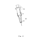
- 1A and 1B are diagrams illustrating a state in which a syringe according to an embodiment is attached to a connector.
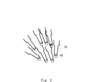
- 1A and 1B are diagrams showing a joint between a connector and a main body according to an embodiment of the present invention.
- 1 is a block diagram showing a configuration of a puncture guide manufacturing device according to an embodiment
- FIG. 13 is a schematic diagram showing a blood vessel pattern transferred onto the puncture guide according to the embodiment.
- Fig. 1 is a schematic diagram of a puncture guide having a plurality of connectors according to the embodiment.
- Fig. 2 is a diagram showing a state in which a syringe according to the embodiment is attached to a connector.
- Fig. 3 is a diagram showing a joint between a connector and a main body according to the embodiment.
- Fig. 5 is a schematic diagram of a puncture guide according to the embodiment in which a blood vessel course is transferred.
- the puncture guide 1 of the present disclosure is used for preoperative marking for a surgical operation such as a resection of a part of a body.
- the puncture guide 1 of the present disclosure is also used for placement of a depot agent, collection of a biopsy tissue, and irradiation of radio waves.
- the puncture guide 1 includes a main body 10 and a connector 20.
- the main body 10 is formed of resin such as plastic.
- the main body 10 has a shape that fits the outer shape of a body part.
- the main body 10 is a member that is shaped so that, when applied to a body part to be examined, diagnosed, or treated, the body part reproduces the shape of the body part when an MRI image, CT image, 3D image, or other image is taken.
- the body part is, for example, a human chest.
- main body 10 that conforms to the external shape of a body part, pressure is applied to the entire soft tissue, such as a human breast, making it less likely to deform during examination, diagnosis, or treatment.
- the main body 10 can be said to fix the shape of the soft tissue, provide strength with less material, and support the connector 20.
- the main body 10 can be made to have excellent strength with less material, for example, by making it a hexagonal mesh structure.
- the material of the main body 10 may be made to have the same softness as the body.
- the material of the main body 10 may be rubber. In this way, the main body 10 will deform in accordance with the deformation of the body during surgery, so the resection position will not shift.
- the main body 10 may be an object that is uniformly formed all over without any holes, or an object with holes arranged in a lattice pattern.
- the main body 10 is fitted with a connector 20 having a recess 21 that guides the base at an appropriate angle and a tip 22 that properly adjusts and fixes the puncture depth of the needle attached to the base.
- the base may be a syringe 30 that administers medicine, a device that collects samples, or a device that generates electromagnetic waves.
- the base of the puncture guide 1 is a syringe for administering medicine, the main body of a biopsy needle, the handle of an electrode needle, etc., and the needle attached to the base punctures the affected area.
- the syringe 30 is used for preoperative marking by injecting a dye.
- the syringe 30 is also used for injecting, for example, an anticancer drug into an appropriate site, for example, for placing a depot drug.
- the base of the puncture guide 1 disclosed herein is a device for collecting samples, it can be used to collect samples from a part of the body through a needle.
- the connector 20 can be used to insert a radio frequency output needle (RFA (Radiofrequency Ablation) needle).
- RFA Radiofrequency Ablation
- the size and shape of the recess 21 of the connector to a size and shape that fits the handle of the RFA needle, the puncture depth and angle of the RFA needle can be adjusted and fixed, allowing radio waves to be applied accurately and easily.
- the main body 10 may be provided with one connector 20 or multiple connectors 20. Multiple connectors 20 allow examination and treatment to be performed on multiple locations on a part of the body.
- the connector 20 has a recess 21 and a tip 22.
- the recess 21 and the tip 22 are distinguished by the difference in shape for fixing the entry position inside the connector 20 of the base.
- the outer cylinder of the syringe 30 is inserted and fixed into the recess 21 of the connector 20.
- the recess 21 of the connector 20 has a size and shape that matches the external shape of the syringe 30. Therefore, the recess 21 is preferably hollow cylindrical or truncated conical so as to fit a typical syringe 30.
- the recess 21 is not limited to this, and the cross section may be triangular, rectangular, or polygonal.
- the tip 22 of the connector 20 is hollow and is the portion through which the needle attached to the syringe 30 passes.
- the tip 22 of the connector 20 is preferably a truncated cone or cylinder with a smaller diameter than the recess 21.
- the shape of the tip 22 is not limited to this, and the cross section may be a triangle, a square, or a polygon.
- the length of the tip 22 of the connector 20 changes depending on the length of the needle of the syringe 30 and the depth to which the drug is to be administered. That is, the length of the tip 22 of the connector 20 changes depending on the length of the needle of the syringe 30 and the depth to which the drug is to be punctured.
- protrusions or steps may be formed in multiple stages inside the recess 21 of the connector 20. When multiple puncture depths are required at the same angle, the recess 21 is provided with protrusions or steps inside so that the base can be fixed at multiple positions. The protrusions or steps act as stoppers for the tip of the outer tube of the syringe 30, and the puncture depth of the needle of the syringe 30 can be adjusted and fixed in multiple stages.
- the puncture angle of the connector 20 is determined in advance when the puncture guide 1 is designed. This is because the affected area, which is the target of puncture, has a three-dimensional shape, and the area is identified by MRI images, CT images, 3D images, or other images taken before examination, diagnosis, and treatment.
- the connector 20 is connected to the main body 10 at an appropriate puncture angle. In this way, the puncture guide 1, which fits the outer shape of the body part, can guide the needle attached to the syringe 30 to the body part at the appropriate depth and angle, making it possible to accurately and easily puncture the affected area.
- the connector 20 may be integral with the main body 10 or may be separate. If the connector 20 is integral with the main body 10 as shown in FIG. 1, the main body 10 and the connector 20 can be molded integrally. Information regarding the size and shape of the connector 20 is stored in advance in an information processing device according to the size and shape of the base to be guided. By acquiring MRI images, CT images, 3D images, or other images of the affected area and part of the body, the puncture depth and angle of the syringe 30 can be determined based on the MRI images, CT images, 3D images, or other images. Therefore, the puncture guide 1 in which the connector 20 and the main body 10 are integrated is designed by acquiring MRI images, CT images, 3D images, or other images. The puncture guide 1 in which the connector 20 and the main body 10 are integrated can be manufactured using a 3D printer based on the design.
- the manufacturing method of the puncture guide 1 is, for example, as follows. First, an MRI image, CT image, 3D image, or other image is taken at a location where there is no manufacturing device for the puncture guide 1, such as a hospital. Then, an information processing device acquires the MRI image, CT image, 3D image, or other image as electronic data by electrical means at a location away from the shooting location, such as the location where a 3D printer is installed. Finally, the puncture guide 1 is manufactured based on the electronic data at the location where the 3D printer is installed.
- the connector 20 can be joined to another main body 10, and the connector 20 can be used with various main bodies 10.
- another connector 20 can be joined to the connector portion of the main body 10, and various connectors 20 can be applied to the connector portion of the main body 10, and the puncture depth of the syringe 30 can be changed by changing the length of the tip 22 of the connector 20.
- the angle between the connector 20 and the main body 10 may be adjusted and fixed in several ways at the joint 40. By changing the angle of the connector 20 using the joint 40 that can be adjusted and fixed, the puncture angle of the syringe 30 can be changed. In this way, by making the joint 40 a separate body that can be adjusted and fixed, the puncture angle at the connector portion can be adjusted.
- Figure 5 shows a puncture guide that omits the connector and adds irregularities 501 that mimic the running of blood vessels.
- the main body 10 of the puncture guide may be provided with irregularities 501 that mimic the running of blood vessels.
- Blood vessels exist inside the body and cannot be seen from the outside, but can be confirmed with MRI images, CT images, etc.
- the irregularities 501 clearly indicate the blood vessels contained in the body's tissues. This allows the surgeon to predict areas that are likely to bleed and require caution before performing surgery.
- the main body 10 may also be provided with an opening such as a window for inserting an ultrasonic examination device.
- the ultrasonic examination device is placed against the affected area to perform an ultrasonic examination of the affected area.
- the three-dimensional size and shape of the target site (e.g., resection area) are taken into consideration, and the puncture depth is shortened as much as possible to reduce the degree of invasiveness, and if there are multiple target sites, the angles of the main body 10 and connector 20 are adjusted by the joint 40 so that the needle paths do not cross and the needle attached to the base reaches the target sites.
- the angles of the connectors 20 are adjusted so that even a single puncture can be performed with minimal invasiveness, and even multiple punctures can be performed three-dimensionally independently with minimal invasiveness.
- the puncture guide 1 is attached to a part of the body, and the base with the needle attached is guided to the connector 20 of the puncture guide, and the needle attached to the base reaches the target site in a fixed manner.
- the size, length and shape of the recess 21 and tip 22 of the connector 20 are adjusted while taking into consideration the thickness of the main body 10 and the joint 40, based on the size and shape of the base and the length of the needle attached to the base, so that the base is smoothly guided and fixed in the recess 21 of the connector 20 and the needle attached to the base reaches the target site (e.g. the resection area).
- the target site e.g. the resection area
- the puncture guide 1, in which the connector 20, joint 40, and main body 10 are separate, is manufactured according to the manufacturing method described above.
- FIG. 4 is a block diagram showing the configuration of a puncture guide manufacturing device according to an embodiment.
- the puncture guide manufacturing device according to an embodiment will be described with reference to FIG. 4.
- the puncture guide manufacturing device 400 is used, for example, to manufacture a puncture guide 1 for applying preoperative marking to an affected area in breast-conserving surgery.
- the puncture guide 1 may guide a needle for placing a depot agent, a needle for collecting a sample, or a needle for outputting radio waves.
- the manufacture of the puncture guide 1 for preoperative marking will be described as an example.
- the puncture guide manufacturing device 400 includes an image acquisition unit 401, an automatic detection unit for the affected area by image analysis 402, a 3D model generation unit for the affected area 403, an automatic design unit for the target area (resection range) 404, a manual adjustment unit for the target area (resection range) 405, an individual design unit for the puncture guide 406, a 3D model generation unit for the puncture guide 407, a storage and editing unit for the surgical plan 408, a reproducibility evaluation unit by image analysis 409, and an information sharing unit between doctors 410.
- the puncture guide manufacturing device 400 may include some of these components, but not all of them.
- the image acquisition unit 401 acquires MRI images, CT images, 3D images, or other images of a patient with an affected area taken at a hospital.
- the image acquisition unit 401 acquires electronic data of the MRI images, CT images, 3D images, or other images via a network such as the Internet or a LAN (Local Area Network) or by using a storage medium such as a memory.
- a network such as the Internet or a LAN (Local Area Network) or by using a storage medium such as a memory.
- the 3D image shows the outer shape of the patient.
- the 3D image can be used to position the puncture guide during surgery.
- AR Augmented Reality
- This AR display is preferably performed on the surgeon's mobile device during surgery.
- the surgeon determines the position of the puncture guide on a mobile device such as a smartphone or tablet.
- the puncture guide manufacturing device 400 is equipped with a 3D image data transmission unit that transmits the 3D image to the mobile device.
- the MRI, CT, 3D or other images may show the condition after RFA ablation or chemotherapy treatment.
- the puncture guide device can be manufactured based on the surgical plan.
- the unit 402 for automatically detecting affected areas through image analysis performs automatic detection of affected areas through image analysis using machine learning artificial intelligence (AI (Artificial Intelligence)).
- AI Artificial Intelligence
- the affected area 3D model generation unit 403 generates a 3D model of the affected area that is automatically detected using technology such as 3D CAD.
- the automatic design unit 404 of the target site (resection range) automatically designs the resection range of the affected area.
- the automatic design unit 404 of the target site (resection range) can design the resection range, for example, by setting the resection range to 1 cm around the affected area. If the puncture guide 1 is not used to resect the affected area, the automatic design unit 404 of the target site (resection range) may not be necessary.
- the manual adjustment unit 405 for the target site (resection range) has a function to manually adjust the resection range of the affected area.
- the affected area calculated by the information processing device may be difficult to resect and may not be appropriate for surgery.
- the affected area detected by the automatic affected area detection unit 402 using image analysis may not be appropriate. Therefore, a function is required for the surgeon or a doctor involved in the surgery to manually adjust the resection range. If the puncture guide 1 is not used to resect the affected area, this manual adjustment unit 405 for the target site (resection range) may not be necessary.
- the individual puncture guide design unit 406 designs the puncture guide 1, which consists of a main body 10 that fits the outer shape of a part of the body, a connector 20 in which the depth and angle of the needle to puncture the affected area are set, and a joint 40. Information regarding the size and shape of the connector 20 is stored in advance in an information processing device according to the size and shape of the guiding base.
- the puncture guide 1 is used to mark the resection area on the patient before surgery.
- the puncture guide 1 may also guide a needle for placing a depot drug, a needle for collecting a sample, or a needle for outputting radio waves.
- the puncture guide 3D model generation unit 407 generates a 3D model so that the puncture guide 1 can be printed by a 3D printer.
- the 3D model generated by the 3D model generation unit is printed by a 3D printer connected to the puncture guide manufacturing device via the Internet, LAN, or directly. Therefore, the puncture guide manufacturing device 400 of the present disclosure may be located away from the hospital and away from the 3D printer.
- the surgical plan storage and editing unit 408 is a part that has the function of allowing the surgeon or a doctor involved in the surgery to store and edit the surgical plan.
- the surgical plan storage and editing unit 408 is preferably provided in the puncture guide manufacturing device 400, but does not have to be included in the manufacturing of the puncture guide 1.
- the repeatability evaluation unit 409 using image analysis is a unit that compares the completed puncture guide 1 3D model with MRI images, CT images, 3D images, or other images, and a 3D model of the affected area, and evaluates whether the surgery is appropriate.
- the repeatability evaluation unit 409 using image analysis may also evaluate whether the position of the preoperative marking is appropriate, whether the placement position of the depot drug is appropriate, whether the position of the sample collection is appropriate, and whether the position of the radio wave output needle is appropriate.
- the information sharing unit 410 between doctors is a section for sharing information between the surgeon and doctors involved in the surgery.
- the information sharing unit 410 between doctors is preferably provided in the puncture guide manufacturing device 400, but does not have to be included in the manufacturing of the puncture guide 1.
- the puncture guide manufacturing device 400 is realized by an information processing device.
- the information processing device includes a processor (e.g., a CPU) that executes a program for processing information, and a memory that stores the program.
- the information processing device may be a single device, or may be configured across multiple devices.
- the information processing device may be configured as a cloud server that executes some or all of its functions in a distributed manner.
- Non-transitory computer-readable media include various types of tangible recording media.
- non-transitory computer-readable media examples include magnetic recording media (e.g., flexible disks, magnetic tapes, hard disk drives), magneto-optical recording media (e.g., magneto-optical disks), CD-ROMs (Read Only Memory), CD-Rs, CD-R/Ws, and semiconductor memories (e.g., mask ROMs, PROMs (Programmable ROMs), EPROMs (Erasable PROMs), flash ROMs, and RAMs (Random Access Memory)).
- the program may be supplied to a computer by various types of temporary computer-readable media. Examples of temporary computer-readable media include electrical signals, optical signals, and electromagnetic waves.
- the temporary computer-readable medium can provide the program to the computer via a wired communication path, such as an electric wire or optical fiber, or via a wireless communication path.
- the puncture guide 1 of the present disclosure is intended to be applied to the chest of a woman, such as a breast cancer patient, but can also be used in other parts of the body that are made of soft tissue.
- the puncture guide disclosed herein can be used in surgical procedures.
- the puncture guide manufacturing device is used to manufacture the puncture guide.
- Puncture guide 10 Main body, 20 Connector, 21 Recess, 22 Tip, 30 Syringe, 40 Joint, 400 Puncture guide manufacturing device, 401 Image acquisition unit, 402 Automatic detection of affected area by image analysis, 403 3D model generation unit of affected area, 404 Automatic design unit of target area (resection range), 405 Manual adjustment unit of target area (resection range), 406 Individual design unit of puncture guide, 407 3D model generation unit of puncture guide, 408 Storage and editing unit of surgical plan, 409 Reproducibility evaluation unit by image analysis, 410 Information sharing unit between doctors, 501 Concave and convex
Landscapes
- Health & Medical Sciences (AREA)
- Life Sciences & Earth Sciences (AREA)
- Veterinary Medicine (AREA)
- Animal Behavior & Ethology (AREA)
- Public Health (AREA)
- Surgery (AREA)
- General Health & Medical Sciences (AREA)
- Engineering & Computer Science (AREA)
- Biomedical Technology (AREA)
- Heart & Thoracic Surgery (AREA)
- Molecular Biology (AREA)
- Oral & Maxillofacial Surgery (AREA)
- Medical Informatics (AREA)
- Nuclear Medicine, Radiotherapy & Molecular Imaging (AREA)
- Pathology (AREA)
- Neurosurgery (AREA)
- Dermatology (AREA)
- Vascular Medicine (AREA)
- Anesthesiology (AREA)
- Hematology (AREA)
- Magnetic Resonance Imaging Apparatus (AREA)
Abstract
穿刺する針の深さ及び角度を調節し、正確にして容易に患部を穿刺するための穿刺ガイド(1)を提供する。針を備える基部を案内し、針が穿刺する深さを調節する凹部(21)を有するコネクタ(20)と、体の一部の外形に適合するように形作られた本体(10)と、を備える穿刺ガイドを提供する。体の一部は、胸部である。また、凹部の内部が段差または突起を備えて、突起または段差により基部に装着された針の穿刺の深さを調節する。基部は、シリンジ(30)であり、体の一部に色素を注入する。穿刺ガイドは、コネクタと本体が一体化されていてもよい。
Description
本開示は穿刺ガイド及びその製造方法、穿刺ガイド製造装置に関する。
人の軟組織に病気や異常が発生することがある。これらの病変(患部)を正確に検査・診断し、適切に治療するには、患部に直接アプローチする必要がある。この検査・診断、治療には、薬剤の投与、試料の採取、電磁波の照射等が挙げられる。MRI(Magnetic Resonance Imaging)画像及びCT(Computed Tomography)画像は患部の位置、大きさ、形状を正確に特定できるため、有力な情報源になる。患部へのアプローチには、侵襲度の低い手法が求められ、例えば穿刺針を用いる方法がある。しかしながら、軟組織は姿勢や体位によって形状が変わるため、患部への正確なアプローチが難しい場合があり、手法の改良が求められている。
乳がん患者の乳房温存手術では、患部と患部の周囲1~1.5cmを切除する。このため、乳房温存手術では、手術前マーキングにより切除範囲を画定することが行われている。しかしながら、人の胸部、特に女性の胸部は、脂肪などの軟組織があり、力が加わると変形するので、正確なマーキングは難しい。
軟部組織中の腫瘍位置を撮像し、治療時にその位置を再現することで、放射線治療を腫瘍部に集中して行うための吸引成型カップが特許文献1に記載されている。撮像時及び治療時に、吸引成型カップが患者の軟部組織を吸引することで軟部組織が吸引成型カップの内面形状に沿って固定されるため、撮像時の腫瘍の位置を再現することができる。これにより、舌先等の動きのある軟部組織であっても、腫瘍位置の特定が容易となり、腫瘍に集中的に放射線を照射することができる。さらに吸引成型カップ自体に腫瘍位置を特定できるガイドを設け、このガイドに沿って線源を設置することで、簡易な器具のみで線源の三次元最適設置が可能になる。
また、非特許文献1には、乳がん患者の乳房温存手術で用いられる3D(Dimension)プリントサージカルガイドが記載されている。化学療法を受けた乳癌患者が乳房温存手術を受けるに当たり、乳房と腫瘍を手術時と同じ体位で撮影したMRI画像に基づいて3Dでモデル化して、3Dプリンタ(3-Dimensional Printer)を用いてサージカルガイドを製造して適用することにより、乳房腫瘍の範囲を正確にマーキングできる。
Zhen-Yu Wu et al. "Breast-conserving surgery with 3D-printed surgical guide: a single-center, prospective clinical study," Sci Rep. 2021 Jan 26;11(1):2252.
特許文献1の吸引成型カップは放射線治療するためのもの、非特許文献1のサージカルガイドは色素注入してマーキングするためのものであるが、いずれも軟組織中の患部に適切な深さ及び角度で正確にアプローチするのは容易でなく、さらに工夫する必要があった。本開示の目的は、穿刺する針の深さ及び角度を適切に調節し、正確にして容易に患部を穿刺するための穿刺ガイドを提供することである。
本開示の穿刺ガイドは、
針を備える基部を案内し、前記針が穿刺する深さを調節する凹部を有するコネクタと、
体の一部の外形に適合するように形作られた本体と、を備える穿刺ガイドである。
針を備える基部を案内し、前記針が穿刺する深さを調節する凹部を有するコネクタと、
体の一部の外形に適合するように形作られた本体と、を備える穿刺ガイドである。
上記構成により、基部に装着された針を体の一部に適切な深さ及び角度で案内し、正確にして容易に患部を穿刺するための穿刺ガイドを提供できる。ここで、本体は、MRI画像、CT画像、3D画像またはその他の画像撮影時の形状を再現するように形作られてもよい。
本開示の穿刺ガイドは、
前記体の一部は、胸部である、ことを特徴とする。
前記体の一部は、胸部である、ことを特徴とする。
上記構成により、穿刺ガイドは、女性の胸部などの軟組織に適用することができ、例えば乳がん患者の乳房温存手術のための検査・診断、治療に用いることができる。
本開示の穿刺ガイドは、
前記凹部の内部に突起または段差を備え、
前記突起または段差により、前記基部に装着された針の穿刺の深さを調節する、ことを特徴とする。
前記凹部の内部に突起または段差を備え、
前記突起または段差により、前記基部に装着された針の穿刺の深さを調節する、ことを特徴とする。
上記構成により、穿刺ガイドは、基部のコネクタ内の進入位置を適切に調節できるので、正確にして容易に患部を穿刺できる。
本開示の穿刺ガイドは、
前記本体は、前記体の血管走行を示す凹凸を有する、ことを特徴とする。
前記本体は、前記体の血管走行を示す凹凸を有する、ことを特徴とする。
上記構成により、手術者は、血液が出やすい注意すべき部位を予測して手術に臨める。
本開示の穿刺ガイドは、
前記本体は、前記体と同程度の軟度を備える、ことを特徴とする。
前記本体は、前記体と同程度の軟度を備える、ことを特徴とする。
上記構成により、手術中、体の変形に合わせて本体10が変形するため切除位置がずれることがない。
本開示の穿刺ガイドは、
前記基部は、シリンジであり、前記体の一部に色素を注入する、ことを特徴とする。
前記基部は、シリンジであり、前記体の一部に色素を注入する、ことを特徴とする。
上記構成により、穿刺ガイドは、手術前マーキングに用いることができる。
本開示の穿刺ガイドは、
前記コネクタと前記本体が一体化されている、ことを特徴とする。
前記コネクタと前記本体が一体化されている、ことを特徴とする。
上記構成により、穿刺ガイドは、本体とコネクタの空間的な配置が固定され、穿刺する針の進入角度を適切に調節して固定できるので、正確にして容易に患部を穿刺できる。
本開示の穿刺ガイドの製造方法は、
上記穿刺ガイドの前記本体と前記コネクタを、前記体の一部のMRI画像、CT画像、3D画像またはその他の画像を用いて設計し、3Dプリンタを用いて製造する、ことを特徴とする。
上記穿刺ガイドの前記本体と前記コネクタを、前記体の一部のMRI画像、CT画像、3D画像またはその他の画像を用いて設計し、3Dプリンタを用いて製造する、ことを特徴とする。
上記構成により、検査・診断、治療前に、MRI画像、CT画像、3D画像またはその他の画像に基づいて3Dプリンタで穿刺ガイドを製造できる。
本開示の穿刺ガイド製造装置は、
患者の患部のMRI画像、CT画像、3D画像またはその他の画像を取得する画像取得部と、
前記MRI画像、CT画像、3D画像またはその他の画像から患部を検出する画像解析による患部の自動検出部と、
前記患部の3Dモデルを生成する患部の3Dモデル生成部と、
前記患部に対する針の穿刺をガイドする請求項1に記載の穿刺ガイドを設計する穿刺ガイドの個別設計部と、
前記穿刺ガイドの3Dモデルを生成する前記穿刺ガイドの3Dモデル生成部と、
前記穿刺ガイドの3Dモデルを前記MRI画像、CT画像、3D画像またはその他の画像、前記患部の3Dモデルと比較し、検査・診断、治療が適当であるか否か評価する画像解析による再現性評価部と、を備える穿刺ガイド製造装置である。
患者の患部のMRI画像、CT画像、3D画像またはその他の画像を取得する画像取得部と、
前記MRI画像、CT画像、3D画像またはその他の画像から患部を検出する画像解析による患部の自動検出部と、
前記患部の3Dモデルを生成する患部の3Dモデル生成部と、
前記患部に対する針の穿刺をガイドする請求項1に記載の穿刺ガイドを設計する穿刺ガイドの個別設計部と、
前記穿刺ガイドの3Dモデルを生成する前記穿刺ガイドの3Dモデル生成部と、
前記穿刺ガイドの3Dモデルを前記MRI画像、CT画像、3D画像またはその他の画像、前記患部の3Dモデルと比較し、検査・診断、治療が適当であるか否か評価する画像解析による再現性評価部と、を備える穿刺ガイド製造装置である。
上記構成により、穿刺する針の深さ及び角度を適切に調節して固定し、正確にして容易に患部を穿刺するための穿刺ガイドを製造する穿刺ガイド製造装置が提供される。
本開示の穿刺ガイド製造装置において、
前記MRI画像、CT画像、3D画像またはその他の画像は、RFAによる焼灼、または化学療法による治療後の状態を示す、ことを特徴とする。
前記MRI画像、CT画像、3D画像またはその他の画像は、RFAによる焼灼、または化学療法による治療後の状態を示す、ことを特徴とする。
上記構成により、手術計画に基づいて、穿刺ガイド装置を製造できる。
本開示の穿刺ガイド装置は、
前記3D画像を用いて、製造された穿刺ガイドが適切に配置されているか否か、AR(Augmented Reality)で判定させるための3D画像データ送信部を備える、ことを特徴とする。
前記3D画像を用いて、製造された穿刺ガイドが適切に配置されているか否か、AR(Augmented Reality)で判定させるための3D画像データ送信部を備える、ことを特徴とする。
上記構成により、ARを用いて、現実世界で穿刺ガイドを配置する位置を示すことができる。
本開示により、穿刺する針の深さ及び角度を適切に調節して固定し、正確にして容易に患部を穿刺するための穿刺ガイドを提供できる。
実施の形態
以下、図面を参照して本発明の実施の形態について説明する。しかしながら、特許請求の範囲にかかる発明を以下の実施の形態に限定するものではない。また、実施の形態で説明する構成の全てが課題を解決するための手段として必須であるとは限らない。説明の明確化のため、以下の記載及び図面は、適宜、省略、及び簡略化がなされている。各図面において、同一の要素には同一の符号が付されており、必要に応じて重複説明は省略されている。
以下、図面を参照して本発明の実施の形態について説明する。しかしながら、特許請求の範囲にかかる発明を以下の実施の形態に限定するものではない。また、実施の形態で説明する構成の全てが課題を解決するための手段として必須であるとは限らない。説明の明確化のため、以下の記載及び図面は、適宜、省略、及び簡略化がなされている。各図面において、同一の要素には同一の符号が付されており、必要に応じて重複説明は省略されている。
(実施の形態にかかる穿刺ガイドの説明)
図1乃至図3及び図5を参照しながら、実施の形態にかかる穿刺ガイドを説明する。図1は、実施の形態にかかる複数のコネクタを備えた穿刺ガイドの概略図である。図2は、実施の形態にかかるシリンジをコネクタに装着した様子を示す図である。図3は、実施の形態にかかるコネクタと本体の接合部を示す図である。図5は、実施の形態にかかる穿刺ガイドに血管走行を転写した概略図である。本開示の穿刺ガイド1は、体の一部の切除術など外科的手術の手術前マーキングに用いられる。また、本開示の穿刺ガイド1は、デポ剤の留置、生検組織の採取、ラジオ波の照射にも用いられる。
図1乃至図3及び図5を参照しながら、実施の形態にかかる穿刺ガイドを説明する。図1は、実施の形態にかかる複数のコネクタを備えた穿刺ガイドの概略図である。図2は、実施の形態にかかるシリンジをコネクタに装着した様子を示す図である。図3は、実施の形態にかかるコネクタと本体の接合部を示す図である。図5は、実施の形態にかかる穿刺ガイドに血管走行を転写した概略図である。本開示の穿刺ガイド1は、体の一部の切除術など外科的手術の手術前マーキングに用いられる。また、本開示の穿刺ガイド1は、デポ剤の留置、生検組織の採取、ラジオ波の照射にも用いられる。
図1に示されるように、実施の形態にかかる穿刺ガイド1は、本体10と、コネクタ20と、を備える。本体10は、例えばプラスチックなどの樹脂で形成される。本体10は、体の一部の外形に適合する形状を有する。言い換えると、本体10は、検査・診断、治療を施す体の一部に適用することにより、当該体の一部がMRI画像、CT画像、3D画像またはその他の画像撮影時の形状を再現するように形作られた部材である。体の一部は例えば人の胸部である。
体の一部の外形に適合する本体10を用いると、圧力が人の乳房など軟組織の全体にかかり、検査・診断、治療を施す際に変形しにくくできる。本体10は、軟組織の形状を固定し、少ない材料で強度を持ち、コネクタ20を支えるものとも言える。図示しないが、本体10は、例えば6角形の網目構造にすることで、より少ない材料で優れた強度を備えることができる。検査・診断、治療時と同じ姿勢、体位でMRI画像、CT画像、3D画像またはその他の画像を撮影して、これに基づいて設計することにより、検査・診断、治療時にMRI画像、CT画像、3D画像またはその他の画像撮影時の体の一部の外形を再現する本体10を製造できる。
本体10の材質を体と同程度の軟度に合わせたものとしてもよい。例えば本体10の材質は、ゴムなどを用いることができる。このようにすると、手術中、体の変形に合わせて本体10が変形するため切除位置がずれることがない。本体10は、穴がなく全体が一様に形成された物体でもよいし、格子状に穴が設けられた物体でもよい。
本体10は、基部を適切な角度で案内する凹部21及び基部に装着された針が穿刺する深さを適切に調節して固定する先端部22を有するコネクタ20が取り付けられる。基部は、薬剤を投与するシリンジ30であってもよいし、試料を採取する装置であってもよいし、電磁波を発生する装置であってもよい。穿刺ガイド1の基部は、薬剤投与用のシリンジ、生検針の本体、電極針のハンドル等であり、当該基部に装着された針が患部を穿刺する。
シリンジ30は、色素を注入する手術前マーキングに用いられる。また、シリンジ30は、例えば抗がん剤の適切な部位への注入、例えばデポ剤の留置に用いられる。
また、本開示の穿刺ガイド1は、基部が試料を採取する装置であれば、針を通して体の一部から試料を採取することができる。
さらに、本開示の穿刺ガイド1は、基部が電磁波を発生する装置であれば、このコネクタ20を利用してラジオ波の出力針(RFA(Radiofrequency Ablation)針)を挿入することもできる。この場合、コネクタの凹部21の大きさと形状をRFA針のハンドルに適合する大きさと形状に設計することで、RFA針の穿刺深さ及び角度を調節して固定し、正確にして容易にラジオ波を照射できる。
ここでは、シリンジ30を例にして基部を説明する。本体10は、1つのコネクタ20が設けられてもよいし、複数のコネクタ20が設けられてもよい。複数のコネクタ20により、体の一部の複数の箇所に検査、治療を施すことができる。
図2に示されるように、コネクタ20は、凹部21と、先端部22と、を備える。凹部21と先端部22は、基部のコネクタ20内の進入位置を固定するための形状の違いにより、区分される。コネクタ20は、シリンジ30の外筒が凹部21に挿入され固定される。コネクタ20の凹部21は、シリンジ30の外形に適合した大きさと形状を有する。したがって、凹部21は、一般的なシリンジ30に適合するよう中空の円筒形または円錐台形であることが好ましい。しかしながら、凹部21は、これに限られず、断面が三角形、四角形、または多角形でもよい。
コネクタ20の先端部22は、中空であり、シリンジ30に装着された針が通過する部分である。コネクタ20の先端部22は、凹部21より径の小さい円錐台形または円筒形であることが好ましい。しかしながら、先端部22の形状は、これに限られず、断面が三角形、四角形、または多角形でもよい。
コネクタ20の先端部22は、シリンジ30の針の長さ及び薬剤を投与する深さに応じて長さを変える。すなわち、コネクタ20の先端部22は、シリンジ30の針の長さ及び穿刺する深さに応じて長さを変える。また、コネクタ20の凹部21の内部に突起または段差を多段階に形成してもよい。同じ角度で複数の深さの穿刺が必要な場合に、凹部21は、基部を複数の位置で固定できるように内部に突起または段差を施される。突起または段差が、シリンジ30の外筒の先端のストッパになり、シリンジ30の針の穿刺の深さを多段階で調節し固定できる。
コネクタ20の穿刺角度は、穿刺ガイド1の設計時に予め決められている。穿刺目標である患部は3次元形状を持ち、検査・診断、治療前に撮影されたMRI画像、CT画像、3D画像またはその他の画像によりその部位が特定されているからである。コネクタ20は、適切な穿刺角度で、本体10と結合されている。このようにして、体の一部の外形に適合した穿刺ガイド1により、シリンジ30に装着された針を体の一部に適切な深さ及び角度で案内して、正確にして容易に患部を穿刺できる。
コネクタ20は、本体10と一体であっても、別体であってもよい。図1に示されるように、コネクタ20が本体10と一体化していれば、本体10とコネクタ20を一体成型できる。コネクタ20の大きさ、形状に関する情報は、案内する基部の大きさ、形状に合わせて、あらかじめ情報処理装置に記憶させておく。患部と体の一部のMRI画像、CT画像、3D画像またはその他の画像を取得することで、MRI画像、CT画像、3D画像またはその他の画像に基づいてシリンジ30の穿刺深さと角度を決めることができる。そのため、コネクタ20と本体10とが一体化した穿刺ガイド1は、MRI画像、CT画像、3D画像またはその他の画像を取得することで設計される。コネクタ20と本体10とが一体化した穿刺ガイド1は、設計に基づいて3Dプリンタを用いて製造されることができる。
穿刺ガイド1の製造方法は、例えば次のようである。まず、穿刺ガイド1の製造装置のない場所、例えば病院でMRI画像、CT画像、3D画像またはその他の画像を撮影する。そして、情報処理装置が、撮影場所から離れた場所、例えば3Dプリンタの設置場所でMRI画像、CT画像、3D画像またはその他の画像を電気的手段により電子データで取得する。最後に、穿刺ガイド1は、3Dプリンタの設置場所で電子データに基づいて製造される。
図3に示されるように、コネクタ20が本体10と別体であれば、コネクタ20を別の本体10と接合でき、コネクタ20をさまざまな本体10に流用できる。言い換えると、本体10のコネクタ部位に別のコネクタ20を接合でき、本体10のコネクタ部位にさまざまなコネクタ20を適用し、コネクタ20の先端部22の長さを変えることで、シリンジ30の穿刺深さを変えることができる。また、コネクタ20と本体10の角度を接合部40で何通りかに調節して固定できるようにしてもよい。調節して固定できる接合部40により、コネクタ20の角度を変えることで、シリンジ30の穿刺角度を変えることができる。このように、接合部40を別体として、調節して固定できるようにすることで、当該コネクタ部位における穿刺角度を調節できる。
図5は、コネクタの記載を省き、血管走行を模した凹凸501を追加した穿刺ガイドを示す。図5に示されるように、穿刺ガイドの本体10は、血管走行を模した凹凸501を備えてもよい。血管は体の内部に存在し、外部から見ることができないが、MRI画像、CT画像などで確認できる。凹凸501は、体の組織に含まれる血管を明示するものである。このため、手術者は、血液が出やすい注意すべき部位を予測して手術に臨める。
また、本体10に、超音波検査装置を挿入するための窓のような開口部を設けてもよい。超音波検査装置を患部に当てることで、患部が超音波検査される。
穿刺ガイドの設計においては、目的部位(例えば切除範囲)の三次元的な大きさと形状を考慮し、できる限り穿刺する深さを短くして侵襲度を減らし、複数の目的部位がある場合には針の経路が交差せずに、基部に装着された針が目的部位に到達するように、接合部40により本体10とコネクタ20との角度を調節する。1つの穿刺であっても低侵襲で施せるように、複数の穿刺であっても三次元的に独立して低侵襲で施せるように、コネクタ20の角度をそれぞれ調節する。上記構成を用いて「針を備える基部を適切な角度で案内」することにより、穿刺ガイド1を体の一部に装着して、針を装着した基部を穿刺ガイドのコネクタ20に案内すると、基部に装着された針が固定的に目的部位に到達する。
穿刺ガイドの設計においては、基部の大きさと形状及び基部に装着された針の長さをもとに、基部がコネクタ20の凹部21で円滑に案内され固定され、基部に装着された針が目的部位(例えば切除範囲)に到達するように、本体10、接合部40の厚みを考慮しつつ、コネクタ20の凹部21及び先端部22の大きさ、長さ、形状を調節する。上記構成を用いて「針が穿刺する深さを適切な深さに調節して固定」することにより、穿刺ガイド1を体の一部に装着して、針を装着した基部を穿刺ガイドのコネクタ20に案内すると、基部に装着された針が固定的に目的部位に到達する。
コネクタ20、接合部40、本体10が別体である穿刺ガイド1は、前述の製造方法に準じて製造される。
(実施の形態にかかる穿刺ガイド製造装置の説明)
図4は、実施の形態にかかる穿刺ガイド製造装置の構成を示すブロック図である。図4を参照しながら、実施の形態にかかる穿刺ガイド製造装置を説明する。穿刺ガイド製造装置400は、例えば乳房温存手術の患部に手術前マーキングを施す穿刺ガイド1の製造に用いられる。また、上記に例示したように、穿刺ガイド1は、デポ剤の留置のための針をガイドしてもよいし、試料採取のための針をガイドしてもよいし、ラジオ波の出力針をガイドしてもよい。ここでは手術前マーキングするための穿刺ガイド1の製造を例にして説明する。
図4は、実施の形態にかかる穿刺ガイド製造装置の構成を示すブロック図である。図4を参照しながら、実施の形態にかかる穿刺ガイド製造装置を説明する。穿刺ガイド製造装置400は、例えば乳房温存手術の患部に手術前マーキングを施す穿刺ガイド1の製造に用いられる。また、上記に例示したように、穿刺ガイド1は、デポ剤の留置のための針をガイドしてもよいし、試料採取のための針をガイドしてもよいし、ラジオ波の出力針をガイドしてもよい。ここでは手術前マーキングするための穿刺ガイド1の製造を例にして説明する。
穿刺ガイド製造装置400は、画像取得部401と、画像解析による患部の自動検出部402と、患部の3Dモデル生成部403と、目的部位(切除範囲)の自動設計部404と、目的部位(切除範囲)の手動調整部405と、穿刺ガイドの個別設計部406と、穿刺ガイドの3Dモデル生成部407と、手術計画の保存及び編集部408と、画像解析による再現性評価部409と、医師間での情報共有部410と、を備える。穿刺ガイド製造装置400は、これらの部分の一部を備え、全部を備えないものでもよい。
画像取得部401は、病院で撮影された患部を有する患者のMRI画像、CT画像、3D画像またはその他の画像を取得する。画像取得部401は、インターネットまたはLAN(Local Area Network)などのネットワークを通じてまたはメモリなどの記憶媒体を用いてMRI画像、CT画像、3D画像またはその他の画像の電子データを取得する。
3D画像は、患者の外形を示すものである。3D画像は、手術の際、穿刺ガイドの位置決めに用いることができる。例えば、AR(Augmented Reality)を用いて、現実世界で穿刺ガイドを配置する位置を示すことができる。このAR表示は、手術中、手術者の携帯端末で行われることが好ましい。手術者は、スマートフォンまたはタブレットなどの携帯端末において、穿刺ガイドの位置を判定する。そのため、穿刺ガイド製造装置400は、3D画像を携帯端末に送信する3D画像データ送信部を備える。
MRI画像、CT画像、3D画像またはその他の画像は、RFAによる焼灼、または化学療法による治療後の状態を示してもよい。このため、手術計画に基づいて、穿刺ガイド装置を製造できる。
画像解析による患部の自動検出部402は、機械学習した人工知能(AI(Artificial Intelligence))を用いた画像解析による患部の自動検出を行う。
患部の3Dモデル生成部403は、3DCADなどの技術を用いて自動検出された患部の3Dモデルを生成する。
目的部位(切除範囲)の自動設計部404は、自動で患部の切除範囲を設計する。目的部位(切除範囲)の自動設計部404は、例えば、切除範囲を患部の周囲1cmなどの設定をすることで、切除範囲を設計できる。穿刺ガイド1が患部の切除に用いられない場合、この目的部位(切除範囲)の自動設計部404はなくてもよい。
目的部位(切除範囲)の手動調整部405は、患部の切除範囲を手動で調整する機能を有する。情報処理装置が計算で導き出した患部範囲は、切除しにくく手術として適切でない場合がある。また、画像解析による患部の自動検出部402で検出した患部が適当でない場合もある。そこで、執刀医または手術に関わる医師が手動で切除範囲を調整する機能が必要である。穿刺ガイド1が患部の切除に用いられない場合、この目的部位(切除範囲)の手動調整部405はなくてもよい。
穿刺ガイドの個別設計部406は、体の一部の外形に適合する本体10、患部に対して穿刺する針の深さ及び角度が設定されたコネクタ20並びに接合部40からなる穿刺ガイド1を設計する。コネクタ20の大きさ、形状に関する情報は、案内する基部の大きさ、形状に合わせて、あらかじめ情報処理装置に記憶させておく。穿刺ガイド1は、患者に切除範囲を手術前マーキングするために用いられる。また、穿刺ガイド1は、デポ剤の留置のための針をガイドしてもよいし、試料採取のための針をガイドしてもよいし、ラジオ波の出力針をガイドしてもよい。
穿刺ガイドの3Dモデル生成部407は、穿刺ガイド1を3Dプリンタで印刷できるように3Dモデルを生成する。3Dモデル生成部で生成された3Dモデルは、穿刺ガイド製造装置とインターネット、LAN、または直接に接続された3Dプリンタで印刷される。したがって、本開示の穿刺ガイド製造装置400は、病院と離れていてもよく、3Dプリンタと離れていてもよい。
手術計画の保存及び編集部408は、執刀医または手術に関わる医師が手術計画を保存及び編集する機能を有する部分である。手術計画の保存及び編集部408は、穿刺ガイド製造装置400に備わっていることが好ましいが、穿刺ガイド1を製造する上ではなくてもよい。
画像解析による再現性評価部409は、出来上がった穿刺ガイド1の3DモデルをMRI画像、CT画像、3D画像またはその他の画像、患部の3Dモデルと比較し、手術が適当であるか否か評価する部分である。また、画像解析による再現性評価部409は、手術前マーキングの位置が適切であるか否か、デポ剤の留置位置が適切であるか否か、試料採取の位置が適切であるか否か、ラジオ波の出力針の位置が適切であるか否か、を評価してもよい。
医師間での情報共有部410は、執刀医及び手術に関わる医師の間で情報共有する部分である。医師間での情報共有部410は、穿刺ガイド製造装置400に備わっていることが好ましいが、穿刺ガイド1を製造する上ではなくてもよい。
穿刺ガイド製造装置400は、情報処理装置によって実現される。情報処理装置は、情報を処理するためのプログラムを実行するプロセッサ(例えばCPU)と、プログラムを記憶するメモリとを備える。情報処理装置は、1つの装置でもよいし、複数の装置に渡って構成されてもよい。情報処理装置は、一部または全部の機能を分散させて実行するクラウドサーバで構成されてもよい。
また、上述した穿刺ガイド製造装置400における処理の一部又は全部は、コンピュータプログラムとして実現可能である。このようなプログラムは、様々なタイプの非一時的なコンピュータ可読媒体を用いて格納され、コンピュータに供給することができる。非一時的なコンピュータ可読媒体は、様々なタイプの実体のある記録媒体を含む。非一時的なコンピュータ可読媒体の例は、磁気記録媒体(例えばフレキシブルディスク、磁気テープ、ハードディスクドライブ)、光磁気記録媒体(例えば光磁気ディスク)、CD-ROM(Read Only Memory)、CD-R、CD-R/W、半導体メモリ(例えば、マスクROM、PROM(Programmable ROM)、EPROM(Erasable PROM)、フラッシュROM、RAM(Random Access Memory))を含む。また、プログラムは、様々なタイプの一時的なコンピュータ可読媒体によってコンピュータに供給されてもよい。一時的なコンピュータ可読媒体の例は、電気信号、光信号、及び電磁波を含む。一時的なコンピュータ可読媒体は、電線及び光ファイバ等の有線通信路、又は無線通信路を介して、プログラムをコンピュータに供給できる。
なお、本発明は上記実施の形態に限られたものではなく、趣旨を逸脱しない範囲で適宜変更することが可能である。例えば、本開示の穿刺ガイド1は、例えば、乳がん患者などの女性の胸部に適用することを想定しているが、軟組織からなる体の一部であれば、そのほかの部分でも用いることができる。
この出願は、2023年6月15日に出願された日本出願特願2023-98361を基礎とする優先権を主張し、その開示の全てをここに取り込む。
本開示の穿刺ガイドは、外科手術に利用できる。穿刺ガイド製造装置は、穿刺ガイドを製造するために用いられる。
1 穿刺ガイド、10 本体、20 コネクタ、21 凹部、22 先端部、30 シリンジ、40 接合部、400 穿刺ガイド製造装置、401 画像取得部、402 画像解析による患部の自動検出部、403 患部の3Dモデル生成部、404 目的部位(切除範囲)の自動設計部、405 目的部位(切除範囲)の手動調整部、406 穿刺ガイドの個別設計部、407 穿刺ガイドの3Dモデル生成部、408 手術計画の保存及び編集部、409 画像解析による再現性評価部、410 医師間での情報共有部、501 凹凸
Claims (11)
- 針を備える基部を案内し、前記針が穿刺する深さを調節する凹部を有するコネクタと、
体の一部の外形に適合するように形作られた本体と、を備える穿刺ガイド。 - 前記体の一部は、胸部である、請求項1に記載の穿刺ガイド。
- 前記凹部の内部は、突起または段差を備え、
前記突起または段差により、前記基部に装着された針の穿刺の深さを調節する、請求項1に記載の穿刺ガイド。 - 前記本体は、前記体の血管走行を示す凹凸を有する、請求項1に記載の穿刺ガイド。
- 前記本体は、前記体と同程度の軟度を備える、請求項1に記載の穿刺ガイド。
- 前記基部は、シリンジであり、前記体の一部に色素を注入する、請求項1に記載の穿刺ガイド。
- 前記コネクタと前記本体が一体化されている、請求項1に記載の穿刺ガイド。
- 請求項7に記載の穿刺ガイドの前記本体と前記コネクタを、前記体の一部のMRI(Magnetic Resonance Imaging)画像、CT(Computed Tomography)画像、3D(Dimension)画像またはその他の画像を用いて設計し、3Dプリンタを用いて製造する、穿刺ガイドの製造方法。
- 患者の患部のMRI画像、CT画像、3D画像またはその他の画像を取得する画像取得部と、
前記MRI画像、CT画像、3D画像またはその他の画像から患部を検出する画像解析による患部の自動検出部と、
前記患部の3Dモデルを生成する患部の3Dモデル生成部と、
前記患部に対する針の穿刺をガイドする請求項1に記載の穿刺ガイドを設計する穿刺ガイドの個別設計部と、
前記穿刺ガイドの3Dモデルを生成する前記穿刺ガイドの3Dモデル生成部と、
前記穿刺ガイドの3Dモデルを前記MRI画像、CT画像、3D画像またはその他の画像、前記患部の3Dモデルと比較し、検査・診断、治療が適当であるか否か評価する画像解析による再現性評価部と、を備える穿刺ガイド製造装置。 - 前記MRI画像、CT画像、3D画像またはその他の画像は、RFAによる焼灼、または化学療法による治療後の状態を示す、請求項9に記載の穿刺ガイド製造装置。
- 前記3D画像を用いて、製造された穿刺ガイドが適切に配置されているか否か、AR(Augmented Reality)で判定させるための3D画像データ送信部を備える、請求項9に記載の穿刺ガイド製造装置。
Priority Applications (1)
| Application Number | Priority Date | Filing Date | Title |
|---|---|---|---|
| JP2025527903A JPWO2024257713A1 (ja) | 2023-06-15 | 2024-06-10 |
Applications Claiming Priority (2)
| Application Number | Priority Date | Filing Date | Title |
|---|---|---|---|
| JP2023098361 | 2023-06-15 | ||
| JP2023-098361 | 2023-06-15 |
Publications (1)
| Publication Number | Publication Date |
|---|---|
| WO2024257713A1 true WO2024257713A1 (ja) | 2024-12-19 |
Family
ID=93851943
Family Applications (1)
| Application Number | Title | Priority Date | Filing Date |
|---|---|---|---|
| PCT/JP2024/020984 Ceased WO2024257713A1 (ja) | 2023-06-15 | 2024-06-10 | 穿刺ガイド及びその製造方法、穿刺ガイド製造装置 |
Country Status (2)
| Country | Link |
|---|---|
| JP (1) | JPWO2024257713A1 (ja) |
| WO (1) | WO2024257713A1 (ja) |
Citations (3)
| Publication number | Priority date | Publication date | Assignee | Title |
|---|---|---|---|---|
| JP2018501879A (ja) * | 2014-12-24 | 2018-01-25 | バイオアルファ コーポレイション | 人工骨組織の製造システム及びその製造方法 |
| US20190365475A1 (en) * | 2011-02-17 | 2019-12-05 | The Trustees Of Dartmouth College | Systems and methods for guiding tissue resection |
| JP2019535413A (ja) * | 2016-11-16 | 2019-12-12 | ジ アサン ファウンデーション | オーダーメイド手術ガイド、オーダーメイド手術ガイド生成方法及び生成プログラム |
-
2024
- 2024-06-10 JP JP2025527903A patent/JPWO2024257713A1/ja active Pending
- 2024-06-10 WO PCT/JP2024/020984 patent/WO2024257713A1/ja not_active Ceased
Patent Citations (3)
| Publication number | Priority date | Publication date | Assignee | Title |
|---|---|---|---|---|
| US20190365475A1 (en) * | 2011-02-17 | 2019-12-05 | The Trustees Of Dartmouth College | Systems and methods for guiding tissue resection |
| JP2018501879A (ja) * | 2014-12-24 | 2018-01-25 | バイオアルファ コーポレイション | 人工骨組織の製造システム及びその製造方法 |
| JP2019535413A (ja) * | 2016-11-16 | 2019-12-12 | ジ アサン ファウンデーション | オーダーメイド手術ガイド、オーダーメイド手術ガイド生成方法及び生成プログラム |
Also Published As
| Publication number | Publication date |
|---|---|
| JPWO2024257713A1 (ja) | 2024-12-19 |
Similar Documents
| Publication | Publication Date | Title |
|---|---|---|
| KR100990553B1 (ko) | 근접 방사선 치료를 위한 장치 | |
| CN111297448B (zh) | 穿刺定位方法、装置及系统 | |
| JP7111680B2 (ja) | デバイス対画像レジストレーションアルゴリズムからの結果の可視化及び操作 | |
| KR101720820B1 (ko) | 수동 조작 의료 기구 시스템 | |
| JP7221190B2 (ja) | 最適化されたデバイス対画像の位置合わせのための構造マスキングまたはアンマスキング | |
| CA3151345A1 (en) | Systems and methods for portable ultrasound guided cannulation | |
| US20150173619A1 (en) | Organ mapping system using an optical coherence tomography probe | |
| US11707259B2 (en) | Wireless needle guidance using encoder sensor and encoder scale to achieve positional sensing between movable components | |
| CN111839730B (zh) | 一种用于引导肿瘤切除的光声成像手术导航平台 | |
| KR102348720B1 (ko) | 니들 가이드 및 이를 포함하는 생검 시술 장치 | |
| CN109893174A (zh) | 一种通过激光引导进行单针或多针穿刺活检的方法 | |
| CN105381534A (zh) | 粒子植入用导板及其制造方法、装置 | |
| JP2015016300A (ja) | 生検支援装置及び生検支援方法 | |
| JP7022723B2 (ja) | マルチプローブ誘導のためのシステムおよび方法 | |
| ES2923501T3 (es) | Dispositivos para guiar procedimientos de tratamiento de tejido y/o extirpación de tejido | |
| CN110731821B (zh) | 基于ct/mri用于肿瘤微创消融术的方法及引导支架 | |
| EP3261550A1 (en) | Apparatus and method for positioning medical instruments assisted by indirect visualization | |
| CN116549116B (zh) | 一种基于3d实时全程量化导航的精准定位系统及方法 | |
| CA2372148A1 (en) | Systems and methods for targeting a breast lesion | |
| WO2024257713A1 (ja) | 穿刺ガイド及びその製造方法、穿刺ガイド製造装置 | |
| JP2022065216A (ja) | 治療方法および治療システム | |
| WO2016135596A1 (en) | Indirect visualization-assisted apparatus and method for positioning medical instruments | |
| CN110664494A (zh) | 一种消融穿刺辅助贴片 | |
| CN113488177A (zh) | 一种基于影像数据的肺部建模方法及系统 | |
| KR102423825B1 (ko) | 환자 맞춤형 정밀 종양 제거 시술을 위한 레이저 정보 연산 방법 및 이를 이용한 자동 레이저 시술 장치 |
Legal Events
| Date | Code | Title | Description |
|---|---|---|---|
| 121 | Ep: the epo has been informed by wipo that ep was designated in this application |
Ref document number: 24823329 Country of ref document: EP Kind code of ref document: A1 |
|
| ENP | Entry into the national phase |
Ref document number: 2025527903 Country of ref document: JP Kind code of ref document: A |
|
| NENP | Non-entry into the national phase |
Ref country code: DE |