WO2024257832A1 - 電極合剤シート、電極、二次電池、及び、電極合剤シートの製造方法 - Google Patents
電極合剤シート、電極、二次電池、及び、電極合剤シートの製造方法 Download PDFInfo
- Publication number
- WO2024257832A1 WO2024257832A1 PCT/JP2024/021514 JP2024021514W WO2024257832A1 WO 2024257832 A1 WO2024257832 A1 WO 2024257832A1 JP 2024021514 W JP2024021514 W JP 2024021514W WO 2024257832 A1 WO2024257832 A1 WO 2024257832A1
- Authority
- WO
- WIPO (PCT)
- Prior art keywords
- electrode mixture
- less
- mixture sheet
- mass
- carbon
- Prior art date
- Legal status (The legal status is an assumption and is not a legal conclusion. Google has not performed a legal analysis and makes no representation as to the accuracy of the status listed.)
- Ceased
Links
Images

Classifications
-
- H—ELECTRICITY
- H01—ELECTRIC ELEMENTS
- H01M—PROCESSES OR MEANS, e.g. BATTERIES, FOR THE DIRECT CONVERSION OF CHEMICAL ENERGY INTO ELECTRICAL ENERGY
- H01M4/00—Electrodes
- H01M4/02—Electrodes composed of, or comprising, active material
- H01M4/13—Electrodes for accumulators with non-aqueous electrolyte, e.g. for lithium-accumulators; Processes of manufacture thereof
- H01M4/131—Electrodes based on mixed oxides or hydroxides, or on mixtures of oxides or hydroxides, e.g. LiCoOx
-
- H—ELECTRICITY
- H01—ELECTRIC ELEMENTS
- H01M—PROCESSES OR MEANS, e.g. BATTERIES, FOR THE DIRECT CONVERSION OF CHEMICAL ENERGY INTO ELECTRICAL ENERGY
- H01M10/00—Secondary cells; Manufacture thereof
- H01M10/05—Accumulators with non-aqueous electrolyte
- H01M10/052—Li-accumulators
- H01M10/0525—Rocking-chair batteries, i.e. batteries with lithium insertion or intercalation in both electrodes; Lithium-ion batteries
-
- H—ELECTRICITY
- H01—ELECTRIC ELEMENTS
- H01M—PROCESSES OR MEANS, e.g. BATTERIES, FOR THE DIRECT CONVERSION OF CHEMICAL ENERGY INTO ELECTRICAL ENERGY
- H01M4/00—Electrodes
- H01M4/02—Electrodes composed of, or comprising, active material
- H01M4/13—Electrodes for accumulators with non-aqueous electrolyte, e.g. for lithium-accumulators; Processes of manufacture thereof
-
- H—ELECTRICITY
- H01—ELECTRIC ELEMENTS
- H01M—PROCESSES OR MEANS, e.g. BATTERIES, FOR THE DIRECT CONVERSION OF CHEMICAL ENERGY INTO ELECTRICAL ENERGY
- H01M4/00—Electrodes
- H01M4/02—Electrodes composed of, or comprising, active material
- H01M4/13—Electrodes for accumulators with non-aqueous electrolyte, e.g. for lithium-accumulators; Processes of manufacture thereof
- H01M4/139—Processes of manufacture
- H01M4/1391—Processes of manufacture of electrodes based on mixed oxides or hydroxides, or on mixtures of oxides or hydroxides, e.g. LiCoOx
-
- H—ELECTRICITY
- H01—ELECTRIC ELEMENTS
- H01M—PROCESSES OR MEANS, e.g. BATTERIES, FOR THE DIRECT CONVERSION OF CHEMICAL ENERGY INTO ELECTRICAL ENERGY
- H01M4/00—Electrodes
- H01M4/02—Electrodes composed of, or comprising, active material
- H01M4/62—Selection of inactive substances as ingredients for active masses, e.g. binders, fillers
- H01M4/621—Binders
- H01M4/622—Binders being polymers
- H01M4/623—Binders being polymers fluorinated polymers
-
- H—ELECTRICITY
- H01—ELECTRIC ELEMENTS
- H01M—PROCESSES OR MEANS, e.g. BATTERIES, FOR THE DIRECT CONVERSION OF CHEMICAL ENERGY INTO ELECTRICAL ENERGY
- H01M4/00—Electrodes
- H01M4/02—Electrodes composed of, or comprising, active material
- H01M4/62—Selection of inactive substances as ingredients for active masses, e.g. binders, fillers
- H01M4/624—Electric conductive fillers
- H01M4/625—Carbon or graphite
-
- H—ELECTRICITY
- H01—ELECTRIC ELEMENTS
- H01M—PROCESSES OR MEANS, e.g. BATTERIES, FOR THE DIRECT CONVERSION OF CHEMICAL ENERGY INTO ELECTRICAL ENERGY
- H01M4/00—Electrodes
- H01M4/02—Electrodes composed of, or comprising, active material
- H01M2004/021—Physical characteristics, e.g. porosity, surface area
-
- H—ELECTRICITY
- H01—ELECTRIC ELEMENTS
- H01M—PROCESSES OR MEANS, e.g. BATTERIES, FOR THE DIRECT CONVERSION OF CHEMICAL ENERGY INTO ELECTRICAL ENERGY
- H01M4/00—Electrodes
- H01M4/02—Electrodes composed of, or comprising, active material
- H01M2004/026—Electrodes composed of, or comprising, active material characterised by the polarity
- H01M2004/028—Positive electrodes
-
- Y—GENERAL TAGGING OF NEW TECHNOLOGICAL DEVELOPMENTS; GENERAL TAGGING OF CROSS-SECTIONAL TECHNOLOGIES SPANNING OVER SEVERAL SECTIONS OF THE IPC; TECHNICAL SUBJECTS COVERED BY FORMER USPC CROSS-REFERENCE ART COLLECTIONS [XRACs] AND DIGESTS
- Y02—TECHNOLOGIES OR APPLICATIONS FOR MITIGATION OR ADAPTATION AGAINST CLIMATE CHANGE
- Y02E—REDUCTION OF GREENHOUSE GAS [GHG] EMISSIONS, RELATED TO ENERGY GENERATION, TRANSMISSION OR DISTRIBUTION
- Y02E60/00—Enabling technologies; Technologies with a potential or indirect contribution to GHG emissions mitigation
- Y02E60/10—Energy storage using batteries
Definitions
- This disclosure relates to an electrode mixture sheet, an electrode, a secondary battery, and a method for manufacturing an electrode mixture sheet.
- Secondary batteries such as lithium-ion secondary batteries are used in small, portable electrical and electronic devices such as notebook computers, mobile phones, smartphones, tablet computers, and ultrabooks because of their high voltage, high energy density, low self-discharge, low memory effect, and the ability to be made extremely lightweight. They are also being put into practical use as a wide range of power sources, including on-board power sources for driving automobiles and large stationary power sources. There is a demand for even higher energy density in secondary batteries, and further improvements in their battery characteristics are required.
- the present disclosure aims to provide an electrode mixture sheet with high tensile strength and low resistance, an electrode and secondary battery using the same, and a method for manufacturing the electrode mixture sheet.
- the present disclosure (1) includes polytetrafluoroethylene, a carbon material, and an electrode active material other than the carbon material and/or a fluororesin other than the polytetrafluoroethylene,
- a value X which is indicated by the interface length/detected amount of carbon, is 2300 or less in an image of a carbon composition distribution obtained by SEM-EDX analysis with a magnification of 2000 times.
- the present disclosure (2) is an electrode mixture sheet according to the present disclosure (1) in which the value X is 300 or more and 2000 or less.
- the present disclosure (3) is an electrode mixture sheet according to the present disclosure (1) or (2), in which the total content of the polytetrafluoroethylene and the fluororesin other than the polytetrafluoroethylene in the electrode mixture sheet is 0.1% by mass or more and 10% by mass or less.
- the present disclosure (5) is an electrode mixture sheet according to any one of the present disclosures (1) to (4), in which the electrode active material other than the carbon material is a positive electrode active material.
- the present disclosure (6) is an electrode mixture sheet according to the present disclosure (5), in which the content of the positive electrode active material is 92% or more and 99% or less by mass relative to the electrode mixture sheet.
- the present disclosure (7) is an electrode including an electrode mixture sheet according to any one of the present disclosures (1) to (6).
- the present disclosure (8) is a secondary battery having the electrode described in the present disclosure (7).
- the present disclosure (9) relates to a process (1) for mixing polytetrafluoroethylene with an electrode active material other than a carbon material and/or a fluororesin other than the polytetrafluoroethylene; Step (2) of mixing the mixture obtained in step (1) with a carbon material.
- the method for producing an electrode mixture sheet includes the steps of:
- the present disclosure (10) is a manufacturing method described in the present disclosure (9) in which fibrils of the polytetrafluoroethylene are generated by shear force in step (1).
- the present disclosure (11) is a manufacturing method described in the present disclosure (9) or (10), in which the mixing in step (2) is performed with a lower shear force than in step (1).
- the present disclosure (12) is a manufacturing method according to any one of the present disclosures (9) to (11), in which all of the components mixed in step (1) are powders, and step (1) is carried out in the absence of a liquid medium.
- the present disclosure (13) is a manufacturing method described in any one of the present disclosures (9) to (12), in which the treatment temperature in step (2) is lower than the treatment temperature in step (1).
- the present disclosure (14) is a manufacturing method described in any one of the present disclosures (9) to (13), in which steps (1) and (2) are performed using the same apparatus.
- the present disclosure provides an electrode mixture sheet with high tensile strength and low resistance, an electrode and secondary battery using the same, and a method for manufacturing the electrode mixture sheet.
- FIG. 1 is a diagram showing an example of spectrum data obtained by SEM-EDX analysis.
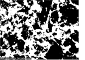
- FIG. 1 is a diagram showing an example of an image of the carbon composition distribution of an electrode mixture sheet obtained by SEM-EDX analysis at a magnification of 2000 times.
- FIG. 1 is a diagram showing an example of an image obtained by binarizing an image obtained by SEM-EDX analysis.
- FIG. 13 is a diagram illustrating a method for calculating an interface length.
- the present disclosure provides an electrode mixture sheet that contains polytetrafluoroethylene (PTFE), a carbon material, and an electrode active material other than the carbon material and/or a fluororesin other than the PTFE, and in an image of the carbon composition distribution obtained by SEM-EDX analysis with a 2000x field of view, the value X shown by the interface length/carbon detection amount is 2300 or less.
- PTFE polytetrafluoroethylene
- the tensile strength of the electrode mixture sheet can be improved and the resistance can be suppressed by setting the value X to 2300 or less. This is considered to be because the dispersion state and shape of the PTFE fibrils located around the carbon material are appropriately controlled.
- the value X is preferably 2000 or less, more preferably 1800 or less, even more preferably 1500 or less, and even more preferably 1300 or less, and is preferably 300 or more, more preferably 450 or more, and even more preferably 750 or more.
- the value X is determined by the following method.
- ⁇ Measurement sample> The electrode mixture sheet is cut into a size of 1 cm x 1 cm (thickness is optional) to prepare a measurement sample.
- the surface containing the electrode mixture is cut into the above size to prepare a measurement sample.
- SEM-EDX scanning electron microscope-energy dispersive X-ray spectroscopy
- the first image is obtained at the center of the measurement sample, and the second and third images are obtained at points shifted 2 mm to the left and right from the center of the measurement sample.
- an SU8000 manufactured by Hitachi High-Tech Corporation can be used to obtain the images.
- the Otsu binarization method is a method for calculating a binarization threshold value in which the point at which the degree of separation between two peaks obtained when a gray-scale histogram is drawn is set as the brightness threshold value.
- the spectrum data used is the spectrum data obtained by measuring with SEM-EDX, with the horizontal axis being X-ray energy [keV] and the vertical axis being X-ray intensity [cps/eV].
- An example of the spectrum data is shown in FIG. 1. From the spectrum data, the maximum value on the vertical axis of the peak appearing near 0.27 keV, which is the specific energy of carbon, is read, and the value thus read is regarded as the amount of carbon detected.
- FIG. 2 shows an example of an image of the carbon composition distribution of an electrode mixture sheet obtained by SEM-EDX analysis at a magnification of 2000 times.
- the image in FIG. 3 is obtained.
- the number of elements whose inter-pixel element difference is not 0 is counted and taken as the interface length.
- the difference between elements between pixels is not 0 means that the colors (white or black) of adjacent pixels (squares) are different, as shown in Figure 4.
- Such edges edges indicated by diagonal lines in the figure
- the number of such elements is 21, and the interface length is 21.
- the electrode mixture sheet of the present disclosure includes PTFE.
- the PTFE may be a homopolymer of tetrafluoroethylene (TFE), or may be a modified PTFE containing a polymerization unit based on TFE (TFE unit) and a polymerization unit based on a modified monomer (hereinafter also referred to as "modified monomer unit").
- TFE unit a polymerization unit based on TFE
- modified monomer unit hereinafter also referred to as "modified monomer unit”
- the modified PTFE may contain 99.0% by mass or more of TFE units and 1.0% by mass or less of modified monomer units.
- the modified PTFE may also be composed of only TFE units and modified monomer units.
- the PTFE is preferably the modified PTFE, which has improved binding power, sheet strength and flexibility.
- the content of modified monomer unit is preferably in the range of 0.00001 to 1.0 mass% based on the total polymerized units, in terms of improving binding force, sheet strength and flexibility.
- the lower limit of the content of modified monomer unit is more preferably 0.0001 mass%, more preferably 0.001 mass%, even more preferably 0.005 mass%, and especially more preferably 0.010 mass%.
- the upper limit of the content of modified monomer unit is preferably 0.90 mass%, more preferably 0.80 mass%, more preferably 0.50 mass%, even more preferably 0.40 mass%, and even more preferably 0.30 mass%.
- the modified monomer unit means a portion of the molecular structure of PTFE that is derived from a modified monomer.
- the modified monomer is not particularly limited as long as it can be copolymerized with TFE, and examples thereof include perfluoroolefins such as hexafluoropropylene [HFP]; hydrogen-containing fluoroolefins such as trifluoroethylene and vinylidene fluoride [VDF]; perhaloolefins such as chlorotrifluoroethylene [CTFE]; perfluorovinyl ethers; perfluoroallyl ethers; (perfluoroalkyl)ethylenes, ethylenes, etc.
- the modified monomers used may be one type or multiple types.
- Rf 1 represents a perfluoro organic group.
- the "perfluoro organic group” refers to an organic group in which all hydrogen atoms bonded to carbon atoms are replaced with fluorine atoms.
- the perfluoro organic group may have an ether oxygen.
- perfluorovinyl ether is perfluoro(alkyl vinyl ether) [PAVE], where Rf 1 in the general formula (A) is a perfluoroalkyl group having 1 to 10 carbon atoms.
- the number of carbon atoms in the perfluoroalkyl group is preferably 1 to 5.
- Examples of the perfluoroalkyl group in the above PAVE include a perfluoromethyl group, a perfluoroethyl group, a perfluoropropyl group, a perfluorobutyl group, a perfluoropentyl group, and a perfluorohexyl group.
- the perfluorovinyl ether further includes those represented by the above general formula (A), in which Rf 1 is a perfluoro(alkoxyalkyl) group having 4 to 9 carbon atoms, and those represented by the following formula:
- Rf 1 is a group represented by the following formula:
- n is an integer from 1 to 4.
- Perfluoroalkyl)ethylenes are not particularly limited, and examples include (perfluorobutyl)ethylene [PFBE] and (perfluorohexyl)ethylene.
- the above Rf2 is preferably a perfluoroalkyl group having 1 to 10 carbon atoms or a perfluoroalkoxyalkyl group having 1 to 10 carbon atoms.
- the above-mentioned perfluoroallyl ether is preferably at least one selected from the group consisting of CF 2 ⁇ CF-CF 2 -O-CF 3 , CF 2 ⁇ CF-CF 2 -O-C 2 F 5 , CF 2 ⁇ CF-CF 2 -O-C 3 F 7 , and CF 2 ⁇ CF-CF 2 -O-C 4 F 9 , more preferably at least one selected from the group consisting of CF 2 ⁇ CF-CF 2 -O-C 2 F 5 , CF 2 ⁇ CF-CF 2 -O-C 3 F 7 , and CF 2 ⁇ CF-CF 2 -O-C 4 F 9 , and even more preferably CF 2 ⁇ CF-CF 2 -O-CF 2 CF 2 CF 3 .
- At least one selected from the group consisting of PAVE, HFP, VDF and CTFE is preferred, as it improves the extensibility, binding strength and flexibility of the composite sheet, and at least one selected from the group consisting of perfluoro(methyl vinyl ether) [PMVE], HFP, VDF and CTFE is more preferred.
- the PTFE may have a core-shell structure.
- An example of a PTFE having a core-shell structure is modified PTFE, which contains a core of high molecular weight PTFE and a shell of lower molecular weight PTFE or modified PTFE in the particle.
- modified PTFE is the PTFE described in JP-A-2005-527652.
- Examples of commonly sold PTFE include F-104, F-106, F-107, F-104C, F-121, F-201, F-205, F-208, and F-302 manufactured by Daikin Industries, 60X, 601X, 602X, 605XTX, 613AX, 62X, 62NX, 62XTX, 640XTX, 641XTX, 650XTX, 669X, 669NX, 6CX, 6CNX, CFP6000X, 6J, 6CJ, 62J, 640J, and 641J manufactured by Chemours, and 3M.
- Examples include TF2029, TF2025Z, TF2053Z, TF2073Z, TF2001Z, TF2071USZ, and TF2072Z; CD145, CD123, CD126E, CD097, CD084E, CD086EL, CD086EH, CD090E, CD122E, CD141E, and CD127E manufactured by AGC; and DF681F, DF680F, DF330F, DF291F, DF230F, DF210F, DF132F, DF130F, and DF120F manufactured by Solvay.
- the PTFE preferably has an endothermic peak temperature of 320° C. or higher, more preferably 325° C. or higher, even more preferably 330° C. or higher, even more preferably 335° C. or higher, even more preferably 340° C. or higher, even more preferably 342° C. or higher, and particularly preferably 344° C. or higher, in that a composite sheet having even greater strength can be formed.
- the endothermic peak temperature is also preferably 350° C. or lower.
- the endothermic peak temperature is the temperature corresponding to the minimum point in the heat of fusion curve obtained by carrying out differential scanning calorimetry (DSC) at a heating rate of 10° C./min on PTFE that has not been heated to a temperature of 300° C. or higher. When there are two or more minimum points in one melting peak, each of them is regarded as an endothermic peak temperature.
- the above PTFE preferably has one or more endothermic peaks in the range of 333 to 347°C in the heat of fusion curve when heated at a rate of 10°C/min using a differential scanning calorimeter [DSC], and the heat of fusion at 290 to 350°C calculated from the heat of fusion curve is 62 mJ/mg or more.
- the PTFE is fibrillated.
- the content of the PTFE in the electrode mixture sheet is preferably 0.1% by mass or more, more preferably 0.2% by mass or more, and even more preferably 0.5% by mass or more, and is preferably 10% by mass or less, more preferably 5% by mass or less, and even more preferably 3% by mass or less.
- the electrode mixture sheet of the present disclosure contains a carbon material.
- the carbon material include a conductive assistant, a carbon-based negative electrode active material, etc.
- the conductive assistant is preferable.
- the content of the carbon material in the electrode mixture sheet is preferably 0.01% by mass or more, more preferably 0.1% by mass or more, and even more preferably 1% by mass or more, and is preferably 99% by mass or less, more preferably 96% by mass or less, and even more preferably 92% by mass or less.
- the conductive additive is not particularly limited, but examples thereof include graphite such as natural graphite and artificial graphite, carbon black such as acetylene black, ketjen black, channel black, furnace black, lamp black, and thermal black, and carbon materials such as needle coke, carbon nanotubes, fullerene, and amorphous carbon such as VGCF. These may be used alone or in any combination and ratio of two or more.
- the content of the conductive assistant in the electrode mixture sheet is preferably 0.01% by mass or more, more preferably 0.1% by mass or more, and even more preferably 1% by mass or more, and is preferably 30% by mass or less, more preferably 15% by mass or less, and even more preferably 5% by mass or less.
- the carbon-based negative electrode active material may be any one selected from artificial graphite, graphite carbon fiber, resin-calcined carbon, pyrolytic vapor-grown carbon, coke, mesocarbon microbeads (MCMB), furfuryl alcohol resin-calcined carbon, polyacene, pitch-based carbon fiber, vapor-grown carbon fiber, natural graphite, and non-graphitizable carbon, or a mixture of two or more of them.
- MCMB mesocarbon microbeads
- the content of the carbon-based negative electrode active material in the electrode mixture sheet is preferably 50% by mass or more, more preferably 60% by mass or more, even more preferably 70% by mass or more, and particularly preferably 75% by mass or more, and is preferably 99% by mass or less, more preferably 96% by mass or less, and even more preferably 92% by mass or less.
- the electrode mixture sheet of the present disclosure contains an electrode active material other than the above carbon material and/or a fluororesin other than the above PTFE (hereinafter also referred to as other fluororesin).
- the content of the electrode active material other than the carbon material and/or the fluororesin other than PTFE is preferably 0.01 mass% or more, more preferably 0.1 mass% or more, and even more preferably 1 mass% or more, relative to the electrode mixture sheet, and is preferably 99 mass% or less, more preferably 96 mass% or less, and even more preferably 92 mass% or less.
- electrode active materials other than the carbon materials include positive electrode active materials and negative electrode active materials other than carbon-based materials. Among these, positive electrode active materials are preferred.
- the positive electrode active material is not particularly limited as long as it can electrochemically absorb and release alkali metal ions, but for example, a material containing an alkali metal and at least one transition metal is preferred. Specific examples include alkali metal-containing transition metal complex oxides and alkali metal-containing transition metal phosphate compounds. Among these, alkali metal-containing transition metal complex oxides that generate high voltage are particularly preferred as the positive electrode active material. Examples of the alkali metal ions include lithium ions, sodium ions, potassium ions, etc., with lithium ions being preferred.
- alkali metal-containing transition metal composite oxide examples include: Formula: M a Mn 2-b M 1 b O 4 (wherein M is at least one metal selected from the group consisting of Li, Na, and K; 0.9 ⁇ a; 0 ⁇ b ⁇ 1.5; M1 is at least one metal selected from the group consisting of Fe, Co, Ni, Cu, Zn, Al, Sn, Cr, V, Ti, Mg, Ca, Sr, B, Ga, In, Si, and Ge), an alkali metal-manganese spinel composite oxide (such as a lithium-manganese spinel composite oxide), Formula : MNi1 - cM2cO2 (wherein M is at least one metal selected from the group consisting of Li, Na, and K; 0 ⁇ c ⁇ 0.5; M2 is at least one metal selected from the group consisting of Fe, Co, Mn, Cu, Zn, Al, Sn, Cr, V, Ti, Mg, Ca, Sr, B, Ga, In, Si, and Ge), or
- MCoO2 , MMnO2 , MNiO2 , MMn2O4 , MNi0.8Co0.15Al0.05O2 , MNi1 /3Co1 / 3Mn1 / 3O2 , or the like is preferred, and a compound represented by the following general formula is preferred.
- M is at least one metal selected from the group consisting of Li, Na, and K
- the transition metal of the lithium-containing transition metal phosphate compound is preferably V, Ti, Cr, Mn, Fe, Co, Ni, Cu, etc., and specific examples thereof include iron phosphates such as LiFePO4 , Li3Fe2 ( PO4 ) 3 , and LiFeP2O7 , cobalt phosphates such as LiCoPO4 , and lithium transition metal phosphate compounds in which a part of the transition metal atoms that constitute the main part of the lithium transition metal phosphate compound is replaced with other elements such as Al, Ti, V, Cr, Mn, Fe, Co, Li, Ni, Cu, Zn, Mg, Ga, Zr, Nb, and Si.
- the lithium-containing transition metal phosphate compound is preferably one having an olivine structure.
- the positive electrode active material include lithium-nickel-based composite oxides.
- the lithium-nickel-based composite oxides are represented by the following general formula: Li y Ni 1-x M x O 2 (wherein x is 0.01 ⁇ x ⁇ 0.7, y is 0.9 ⁇ y ⁇ 2.0, and M is a metal atom (excluding Li and Ni)) is preferred.
- positive electrode active material examples include MFePO 4 , MNi 0.8 Co 0.2 O 2 , M 1.2 Fe 0.4 Mn 0.4 O 2 , MNi 0.5 Mn 1.5 O 2 , MV 3 O 6 , and M 2 MnO 3 .
- positive electrode active materials such as M 2 MnO 3 and MNi 0.5 Mn 1.5 O 2 are preferred in that the crystal structure does not collapse even when the secondary battery is operated at a voltage exceeding 4.4 V or a voltage of 4.6 V or more.
- the positive electrode active material include a solid solution material of M2MnO3 and MM6O2 (wherein M is at least one metal selected from the group consisting of Li, Na, and K, and M6 is a transition metal such as Co, Ni, Mn, or Fe).
- manganese-containing solid solution materials such as Li1.2Mn0.5Co0.14Ni0.14O2 , which are based on Li2MnO3 and contain LiNiO2 or LiCoO2 as a solid solution, are preferred because they can provide an alkali metal ion secondary battery having a high energy density.
- lithium phosphate in the positive electrode active material, since this improves the continuous charging characteristics.
- the amount of lithium phosphate used is preferably 0.1% by mass or more, more preferably 0.3% by mass or more, and even more preferably 0.5% by mass or more, with respect to the total of the positive electrode active material and lithium phosphate, and is preferably 10% by mass or less, more preferably 8% by mass or less, and even more preferably 5% by mass or less.
- a material having a different composition may be attached to the surface of the positive electrode active material.
- surface-attached materials include oxides such as aluminum oxide, silicon oxide, titanium oxide, zirconium oxide, magnesium oxide, calcium oxide, boron oxide, antimony oxide, and bismuth oxide; sulfates such as lithium sulfate, sodium sulfate, potassium sulfate, magnesium sulfate, calcium sulfate, and aluminum sulfate; carbonates such as lithium carbonate, calcium carbonate, and magnesium carbonate; and carbon.
- the content of the positive electrode active material in the electrode mixture sheet is preferably 50% by mass or more, more preferably 60% by mass or more, even more preferably 70% by mass or more, particularly preferably 75% by mass or more, and most preferably 92% by mass or more, and is preferably 99% by mass or less, more preferably 98% by mass or less, and even more preferably 97% by mass or less.
- Examples of the negative electrode active material other than the carbon-based material include any one selected from lithium metal, silicon-containing compounds such as silicon and silicon alloys, Li 4 Ti 5 O 12 , and the like, or a mixture of two or more of them.
- non-carbon-based negative electrode active materials preferably contain silicon as a constituent element.
- a material that contains silicon as a constituent element By using a material that contains silicon as a constituent element, a high-capacity battery can be produced.
- silicon oxide is a general term for amorphous silicon oxide, and silicon oxide before disproportionation is represented by the general formula SiOx (0.5 ⁇ x ⁇ 1.6).
- x is preferably 0.8 ⁇ x ⁇ 1.6, and more preferably 0.8 ⁇ x ⁇ 1.3.
- This silicon oxide can be obtained, for example, by heating a mixture of silicon dioxide and metallic silicon to produce silicon monoxide gas, which is then cooled and precipitated.
- the content of the negative electrode active material other than the carbon material is preferably 1% by mass or more, more preferably 2% by mass or more, even more preferably 5% by mass or more, and particularly preferably 8% by mass or more, relative to the electrode mixture sheet, and is preferably 97% by mass or less, more preferably 90% by mass or less, and even more preferably 80% by mass or less.
- the other fluororesins mentioned above include PTFEs other than the PTFE mentioned above as an essential component (hereinafter, also referred to as other PTFEs), melt-processable fluororesins, etc.
- PTFEs other than the PTFE mentioned above as an essential component
- melt-processable fluororesins etc.
- the other PTFEs mentioned above are preferred in that they can provide higher tensile strength and lower resistance.
- PTFE with different compositions include PTFE with different types of modified monomers copolymerizable with tetrafluoroethylene (TFE) and/or different contents of polymerized units (modified monomer units) based on those modified monomers.
- TFE tetrafluoroethylene
- the combination of PTFE as the essential component and PTFE with a different composition may be, for example, a combination of a homopolymer of TFE and modified PTFE, a combination of two or more modified PTFEs with different types of modified monomers, or a combination of two or more PTFEs having the same modified monomer unit but with different content ratios of the modified monomer unit.
- "Different content ratios of modified monomer units” means that the difference in the content ratios (mass % value) of the modified monomer units in all polymerized units is 0.005 or more.
- the difference in the content ratios is preferably 0.10 or more, more preferably 0.15 or more, even more preferably 0.20 or more, and preferably 0.80 or less, more preferably 0.60 or less, and even more preferably 0.40 or less.
- a particularly preferred combination is a homopolymer of tetrafluoroethylene (TFE) and modified PTFE.
- a homopolymer of TFE refers to one in which the content of modified monomer units relative to the total polymerized units is less than 0.0001% by mass.
- modified PTFE as PTFE with different compositions include the same modified PTFE as described above for PTFE as an essential component.
- the other PTFE may be a PTFE having a different standard specific gravity (SSG) from the PTFE as the essential component.
- SSG standard specific gravity
- "Different SSG” means that the difference in SSG is 0.005 or more.
- the difference in SSG is preferably 0.010 or more, more preferably 0.015 or more, even more preferably 0.020 or more, and is preferably 0.050 or less, more preferably 0.040 or less, and even more preferably 0.030 or less.
- the other PTFE may be a PTFE having a different extrusion pressure from the PTFE as the essential component.
- "Different extrusion pressure” means that the difference in extrusion pressure is 5 MPa or more.
- the difference in extrusion pressure is preferably 10 MPa or more, more preferably 15 MPa or more, even more preferably 20 MPa or more, and is preferably 35 MPa or less, more preferably 30 MPa or less, and even more preferably 25 MPa or less.
- the extrusion pressure is measured by the following method. In the latter half of the extrusion operation in the paste extrusion described below, the load (N) when the pressure reaches an equilibrium state is divided by the cross-sectional area of the cylinder to obtain the extrusion pressure (MPa).
- melt-processable fluororesin examples include tetrafluoroethylene [TFE]/perfluoro(alkyl vinyl ether) [PAVE] copolymer [PFA], TFE/hexafluoropropylene [HFP] copolymer [FEP], ethylene [Et]/TFE copolymer [ETFE], Et/TFE/HFP copolymer [EFEP], polychlorotrifluoroethylene [PCTFE], chlorotrifluoroethylene [CTFE]/TFE copolymer, CTFE/TFE/P
- perfluoroalkyl allyl ether examples include AVE copolymer, Et/CTFE copolymer, polyvinyl fluoride [PVF], polyvinylidene fluoride [PVdF], vinylidene fluoride [VdF]/TFE copolymer, VdF/HFP copolymer, VdF/TFE/HFP copolymer, VdF/HFP/
- the perfluoroalkyl allyl ether is a monomer represented by CF 2 ⁇ CFCF 2 -O-Rf 3 (Rf 3 is a perfluoroalkyl group having 1 to 5 carbon atoms).
- Rf 3 is a perfluoroalkyl group having 1 to 5 carbon atoms.
- PVdF polyvinylidene fluoride
- melt processable means that the polymer is capable of being melted and processed using conventional processing equipment such as extruders and injection molders.
- the melt-processable fluororesin preferably has a melt flow rate (MFR) of 0.1 g/10 min or more, more preferably 0.5 g/10 min or more, and preferably 100 g/10 min or less, more preferably 50 g/10 min or less.
- MFR is a value obtained in accordance with ASTM D1238 using a melt indexer at a measurement temperature determined depending on the type of fluoropolymer (e.g., 372°C for PFA and FEP, and 297°C for ETFE) and a load (e.g., 5 kg for PFA, FEP, and ETFE) as the mass of polymer flowing out per 10 minutes from a nozzle having an inner diameter of 2 mm and a length of 8 mm (g/10 min).
- a load e.g., 5 kg for PFA, FEP, and ETFE
- the mass ratio of PTFE as the essential component to the other fluororesin is preferably 1/99 or more, more preferably 5/95 or more, even more preferably 10/90 or more, even more preferably 15/85 or more, and particularly preferably 20/80 or more, and is preferably 99/1 or less, more preferably 95/5 or less, even more preferably 90/10 or less, even more preferably 85/15 or less, and particularly preferably 80/20 or less.
- the total content of the essential components PTFE and the other fluororesins is preferably 0.1% by mass or more, more preferably 0.2% by mass or more, and even more preferably 0.5% by mass or more, relative to the electrode mixture sheet, and is preferably 10% by mass or less, more preferably 5% by mass or less, and even more preferably 3% by mass or less.
- the electrode mixture sheet of the present disclosure particularly preferably contains PTFE, a carbon material as a conductive assistant, and a positive electrode active material.
- the electrode mixture sheet may be a positive electrode mixture sheet.
- the PTFE, conductive assistant, and positive electrode active material in this embodiment may be the above-mentioned ones.
- the PTFE content in the above embodiment is preferably 0.1 mass% or more, more preferably 0.2 mass% or more, and even more preferably 0.5 mass% or more, relative to the electrode mixture sheet, and is preferably 10 mass% or less, more preferably 5 mass% or less, and even more preferably 3 mass% or less.
- the content of the carbon material (conductive assistant) in the above embodiment is preferably 0.01 mass% or more, more preferably 0.1 mass% or more, and even more preferably 1 mass% or more, relative to the electrode mixture sheet, and is preferably 30 mass% or less, more preferably 15 mass% or less, and even more preferably 5 mass% or less.
- the content of the positive electrode active material in the above embodiment is preferably 50% by mass or more, more preferably 60% by mass or more, even more preferably 70% by mass or more, and particularly preferably 75% by mass or more, relative to the electrode mixture sheet, and is preferably 99% by mass or less, more preferably 98% by mass or less, and even more preferably 97% by mass or less.
- the PTFE as the essential component and the other fluororesin (if present) act as binders, but may further contain other binders.
- the other binder is not particularly limited, and examples thereof include resin-based polymers such as polyethylene, polypropylene, polyethylene terephthalate, polymethyl methacrylate, aromatic polyamide, chitosan, alginic acid, polyacrylic acid, polyimide, cellulose, and nitrocellulose; rubber-like polymers such as SBR (styrene-butadiene rubber), isoprene rubber, butadiene rubber, fluororubber, NBR (acrylonitrile-butadiene rubber), and ethylene-propylene rubber; styrene-butadiene-styrene block copolymers or hydrogenated products thereof; thermoplastic elastomeric polymers such as EPDM (ethylene-propylene-diene terpolymer), styrene-ethylene-butadiene-s
- the content of the other binders is usually 0.01 to 3 mass% of the electrode mixture sheet.
- the electrode mixture sheet of the present disclosure may further include a solid electrolyte. That is, the electrode mixture sheet of the present disclosure may be an electrode mixture sheet for a solid-state battery that includes an electrode active material and a solid electrolyte.
- the solid electrolyte may be a sulfide-based solid electrolyte or an oxide-based solid electrolyte.
- a sulfide-based solid electrolyte when used, there is an advantage in that the flexibility of the sheet is improved.
- the sulfide-based solid electrolyte preferably contains lithium.
- Sulfide-based solid electrolytes containing lithium are used in solid-state batteries that use lithium ions as a carrier, and are particularly preferred in that the electrochemical device has a high energy density.
- the oxide-based solid electrolyte is preferably a compound that contains oxygen atoms (O), has the ionic conductivity of a metal belonging to Group 1 or 2 of the periodic table, and has electronic insulation properties.
- Ceramic materials in which elements have been substituted for LLZ are also known.
- Ceramic materials in which elements have been substituted for LLZ are also known.
- Li6.24La3Zr2Al0.24O11.98 Li6.25Al0.25La3Zr2O12 , Li6.6La3Zr1.6Ta0.4O12, Li6.75La3Zr1.75Nb0.25O12 , etc. , in which LLZ is partially substituted with Al
- Li6.6La3Zr1.6Ta0.4O12 , Li6.75La3Zr1.75Nb0.25O12 , etc. in which LLZ is partially substituted with Ta , etc.
- LLZ-based ceramic materials in which at least one element of Mg (magnesium) and A (A is at least one element selected from the group consisting of Ca ( calcium ) , Sr (strontium), and Ba (barium)) is substituted for LLZ can be mentioned.
- phosphorus compounds containing Li, P, and O are also desirable.
- the lithium phosphate include lithium phosphate (Li 3 PO 4 ), LiPON in which part of the oxygen in lithium phosphate is replaced with nitrogen, LiPOD 1 (D 1 is at least one selected from Ti, V, Cr, Mn, Fe, Co, Ni, Cu, Zr, Nb, Mo, Ru, Ag, Ta, W, Pt, Au, etc.), etc.
- LiA 1 ON is at least one selected from Si, B, Ge, Al, C, Ga, etc.
- Specific examples include Li 2 O-Al 2 O 3 -SiO 2 -P 2 O 5 -TiO 2 -GeO 2 , Li 2 O-Al 2 O 3 -SiO 2 -P 2 O 5 -TiO 2 , etc.
- the oxide-based solid electrolyte preferably contains lithium.
- the oxide-based solid electrolyte containing lithium is used in solid-state batteries that use lithium ions as a carrier, and is particularly preferred in that it is an electrochemical device having a high energy density.
- the oxide-based solid electrolyte is preferably an oxide having a crystalline structure.
- Oxides having a crystalline structure are particularly preferred in terms of good Li ion conductivity.
- Examples of oxides having a crystalline structure include perovskite type (La0.51Li0.34TiO2.94, etc.), NASICON type (Li1.3Al0.3Ti1.7(PO4)3, etc.), and garnet type (Li7La3Zr2O12 ( LLZ ) , etc. ) .
- NASICON type is preferred.
- the volume average particle diameter of the oxide-based solid electrolyte is not particularly limited, but is preferably 0.01 ⁇ m or more, and more preferably 0.03 ⁇ m or more.
- the upper limit is preferably 100 ⁇ m or less, and more preferably 50 ⁇ m or less.
- the average particle diameter of the oxide-based solid electrolyte particles is measured by the following procedure.
- the oxide-based solid electrolyte particles are diluted and adjusted to a 1 mass % dispersion in a 20 ml sample bottle using water (heptane in the case of a substance unstable in water).
- the diluted dispersion sample is irradiated with 1 kHz ultrasound for 10 minutes and used for testing immediately thereafter.
- the content of the solid electrolyte in the electrode mixture sheet is preferably 10% by mass or more, more preferably 15% by mass or more, and even more preferably 20% by mass or more, and is preferably 50% by mass or less, more preferably 40% by mass or less, and even more preferably 35% by mass or less.
- the electrode mixture sheet of the present disclosure preferably has a thickness of 300 ⁇ m or less, more preferably 250 ⁇ m or less, even more preferably 200 ⁇ m or less, even more preferably 180 ⁇ m or less, and particularly preferably 150 ⁇ m or less, and preferably 10 ⁇ m or more, more preferably 15 ⁇ m or more, and even more preferably 20 ⁇ m or more.
- the electrode mixture sheet of the present disclosure preferably has a tensile strength of 0.10 N/mm2 or more , more preferably 0.15 N/mm2 or more , even more preferably 0.20 N/ mm2 or more, even more preferably 0.25 N/ mm2 or more, particularly preferably 0.30 N/mm2 or more , and may be 1.5 N/mm2 or less , or may be 1.0 N/mm2 or less .
- the tensile strength is measured by the following method. The electrode mixture sheet is cut out to prepare a 4 mm wide rectangular test piece. Measurements are performed using a tensile tester (Shimadzu Corporation AGS-100NX) at 100 mm/min. The chuck distance is 40 mm. Displacement is applied until breakage occurs, and the maximum stress of the measurement is taken as the tensile strength.
- the electrode mixture sheet of the present disclosure can be obtained, for example, by a manufacturing method for an electrode mixture sheet including a step (1) of mixing PTFE with an electrode active material other than a carbon material and/or the above-mentioned fluororesin other than PTFE (other fluororesin), and a step (2) of mixing the mixture obtained in the step (1) with a carbon material.
- the present disclosure also relates to such a method of manufacture. It is believed that adding the carbon material later reduces damage to the carbon material caused by shear forces that generate fibrils, making it less likely that the conductive paths will be damaged and reducing resistance.
- the PTFE, the electrode active material other than the carbon material, and the other fluororesin in the above step (1) are the same as those described in the electrode mixture sheet of the present disclosure.
- a solid electrolyte it is preferable to mix it in step (1).
- the components mixed in step (1) above are preferably in the form of powder. In the above step (1), it is preferable not to mix a carbon material.
- the above step (1) is preferably carried out in the absence of a liquid medium.
- the mixing method in the above step (1) includes a method of mixing using a single-shaft kneader, a twin-shaft kneader, a mix muller, a high-speed stirring mixer, a planetary mixer, a jet mill, etc.
- the mixing conditions may be appropriately set to the rotation speed and mixing time.
- the rotation speed is preferably 10,000 rpm or less. It is preferably 500 rpm or more, more preferably 1,000 rpm or more, and even more preferably 1,500 rpm or more, and also preferably 8,000 rpm or less, more preferably 6,000 rpm or less, and even more preferably 5,000 rpm or less.
- the mixing time is preferably 60 minutes or less. It is preferably 1 minute or more, more preferably 2 minutes or more, and even more preferably 3 minutes or more, and is preferably 30 minutes or less, more preferably 20 minutes or less, and even more preferably 10 minutes or less.
- step (1) it is preferable to generate fibrils of the PTFE by shear force.
- the processing temperature may be set appropriately.
- the processing temperature is preferably 150°C or less, more preferably 120°C or less, and even more preferably 100°C or less, and is preferably 30°C or more, more preferably 40°C or more, and even more preferably 50°C or more.
- the materials may be mixed and then molded into a bulk shape.
- Specific methods for molding into a bulk shape include extrusion molding and press molding.
- bulk shape does not specify a particular shape, and may refer to a state in which the material is in the form of a single mass, and includes shapes such as rods, sheets, spheres, and cubes.
- the above step (2) is preferably carried out in the absence of a liquid medium.
- the mixing method in step (2) above can also include mixing methods using a W-type mixer, V-type mixer, drum-type mixer, ribbon mixer, conical screw-type mixer, etc.
- the mixing in the step (2) is preferably performed with a lower shear force than that in the step (1).
- the value X can be more easily adjusted to fall within the above-mentioned range, and an electrode mixture sheet having a higher tensile strength and a lower resistance can be produced.
- the shear force in step (2) can be adjusted to a range lower than that in step (1) by using an apparatus capable of applying a lower shear force than that in step (1) or by setting any one or more of the processing time, the rotation speed of the apparatus, the input amount, and the processing temperature lower than those in step (1).
- the processing time is preferably shorter than that of the above step (1), and is preferably 0.9 times or less, more preferably 0.8 times or less, even more preferably 0.6 times or less, and is preferably 0.1 times or more, more preferably 0.2 times or more, even more preferably 0.3 times or more, based on the above step (1).
- the rotation speed is preferably lower than that in step (1) above, and is preferably 0.9 times or less, more preferably 0.8 times or less, even more preferably 0.7 times or less, and is preferably 0.01 times or more, more preferably 0.05 times or more, even more preferably 0.1 times or more, and even more preferably 0.2 times or more, based on the rotation speed in step (1) above.
- the amount of the compound added is preferably smaller than that in step (1) above, and is preferably 0.9 times or less, more preferably 0.8 times or less, even more preferably 0.6 times or less, and is preferably 0.2 times or more, more preferably 0.3 times or more, even more preferably 0.4 times or more, based on the amount of the compound added in step (1) above.
- the treatment temperature is preferably lower than that in the above step (1), and is preferably at most 10°C lower, more preferably at most 20°C lower, even more preferably at most 30°C lower, and is preferably at least 200°C lower, more preferably at least 150°C lower, even more preferably at least 100°C lower, based on the above step (1). It is preferable that the step (2) is carried out using the same apparatus as the step (1), and it is particularly preferable that the same apparatus as the step (1) is used, but with different rotation speed and processing time.
- the above manufacturing method preferably further includes a step (3) of rolling the electrode mixture obtained in the above step (2) into a sheet.
- the rolling method in the above step (3) include rolling methods using a roll press, a plate press, a calendar roll machine, or the like.
- a roll press machine in which metal rolls are arranged opposite to each other, and a calender roll machine in which a plurality of metal rolls are further arranged are preferable.
- the transport speed of the downstream roll is preferably 1.1 times or more, more preferably 1.3 times or more, and even more preferably 1.5 times or more, based on the transport speed of the upstream roll.
- the upstream roll is moved at a low speed without being stopped.
- a step (4) may be carried out in which a larger load is applied to the obtained rolled sheet to roll it into a thinner sheet, or the step (4) may be carried out repeatedly.
- the number of times of step (4) is preferably 2 to 10 times, more preferably 3 to 9 times.
- Specific rolling methods include, for example, a method in which two or more rolls are rotated and the rolled sheet is passed between them to process it into a thinner sheet.
- the treatment temperature may be appropriately set.
- the treatment temperature is preferably 250° C. or less, more preferably 200° C. or less, and even more preferably 180° C. or less, and is preferably 30° C. or more, more preferably 40° C. or more, and even more preferably 50° C. or more. Heating the material makes it flexible and improves its processability.
- the electrode mixture sheet of the present disclosure can be used as an electrode mixture sheet for a secondary battery. It can be used for either a negative electrode or a positive electrode. In particular, the electrode mixture sheet is suitable for a lithium ion secondary battery.
- the present disclosure also provides an electrode including the electrode mixture sheet of the present disclosure described above.
- the electrode of the present disclosure has high tensile strength and low resistance.
- the electrode of the present disclosure may include the electrode mixture sheet of the present disclosure described above and a current collector.
- the electrodes of the present disclosure may be positive or negative electrodes.
- the positive electrode is preferably composed of a current collector and an electrode mixture sheet containing the positive electrode active material.
- materials for the positive electrode current collector include metals such as aluminum, titanium, tantalum, stainless steel, and nickel, or metal materials such as alloys thereof; and carbon materials such as carbon cloth and carbon paper. Among these, metal materials, particularly aluminum or its alloys, are preferred.
- a conductive assistant is applied to the surface of the current collector in order to reduce the electrical contact resistance between the current collector and the positive electrode active material layer.
- conductive assistants include carbon and precious metals such as gold, platinum, and silver.
- the positive electrode may be manufactured by a conventional method.
- an electrode mixture sheet and a current collector may be laminated with an adhesive and then vacuum dried.
- the density of the positive electrode mixture sheet is preferably 2.80 g/cm 3 or more, more preferably 3.00 g/cm 3 or more, and even more preferably 3.20 g/cm 3 or more, and is preferably 3.80 g/cm 3 or less, more preferably 3.75 g/cm 3 or less, and even more preferably 3.70 g/cm 3 or less. If it exceeds this range, the permeability of the electrolyte solution near the current collector/active material interface decreases, and the charge/discharge characteristics, especially at high current density, may decrease and high output may not be obtained. If it is below this range, the conductivity between the active materials decreases, the battery resistance increases, and high output may not be obtained.
- the negative electrode is preferably composed of a current collector and an electrode mixture sheet containing the negative electrode active material.
- materials for the negative electrode current collector include metals such as copper, nickel, titanium, tantalum, and stainless steel, or metal materials such as alloys thereof; and carbon materials such as carbon cloth and carbon paper. Among these, metal materials, particularly copper, nickel, and alloys thereof, are preferred.
- the shape of the current collector may be metal foil, metal cylinder, metal coil, metal plate, expanded metal, punched metal, foam metal, etc. for metal materials, or carbon plate, carbon thin film, carbon cylinder, etc. for carbon materials. Of these, metal foil is preferred.
- the metal foil may be appropriately formed into a mesh shape.
- the thickness of the metal foil is optional, but is usually 1 ⁇ m or more, preferably 3 ⁇ m or more, more preferably 5 ⁇ m or more, and is usually 1 mm or less, preferably 100 ⁇ m or less, more preferably 50 ⁇ m or less. If the metal foil is thinner than this range, the strength required as a current collector may be insufficient. Conversely, if the metal foil is thicker than this range, handling may be impaired.
- the negative electrode may be manufactured by a conventional method.
- the electrode mixture sheet and the current collector may be laminated with an adhesive and then vacuum dried.
- the density of the negative electrode mixture is preferably 1.3 g/cm 3 or more, more preferably 1.4 g/cm 3 or more, and even more preferably 1.5 g/cm 3 or more, and is preferably 2.0 g/cm 3 or less, more preferably 1.9 g/cm 3 or less, and even more preferably 1.8 g/cm 3 or less. If it exceeds this range, the permeability of the electrolyte solution near the current collector/active material interface decreases, and the charge/discharge characteristics, especially at high current density, may decrease and high output may not be obtained. If it is below this range, the conductivity between the active materials decreases, the battery resistance increases, and high output may not be obtained.
- the present disclosure also provides a secondary battery having the electrode of the present disclosure described above.
- the secondary battery may be a secondary battery that uses an electrolyte solution, or may be a solid-state secondary battery.
- the solid-state secondary battery may be a secondary battery containing a solid electrolyte, and may be a semi-solid secondary battery containing a solid electrolyte and a liquid component as the electrolyte, or may be an all-solid-state secondary battery containing only a solid electrolyte as the electrolyte.
- Secondary batteries using the above electrolyte can use electrolytes, separators, etc. that are used in known secondary batteries. These are described in detail below.
- a non-aqueous electrolyte is preferably used.
- a solution in which a known electrolyte salt is dissolved in a known organic solvent for dissolving electrolyte salts can be used.
- the organic solvent for dissolving the electrolyte salt is not particularly limited, but one or more of the following can be used: known hydrocarbon solvents such as propylene carbonate, ethylene carbonate, butylene carbonate, ⁇ -butyrolactone, 1,2-dimethoxyethane, 1,2-diethoxyethane, dimethyl carbonate, diethyl carbonate, and ethyl methyl carbonate; and fluorine-based solvents such as fluoroethylene carbonate, fluoroether, and fluorinated carbonate.
- hydrocarbon solvents such as propylene carbonate, ethylene carbonate, butylene carbonate, ⁇ -butyrolactone, 1,2-dimethoxyethane, 1,2-diethoxyethane, dimethyl carbonate, diethyl carbonate, and ethyl methyl carbonate
- fluorine-based solvents such as fluoroethylene carbonate, fluoroether, and fluorinated carbonate.
- the electrolyte salt may be a lithium salt, such as LiClO4 , LiAsF6 , LiBF4, LiPF6 , LiN( SO2CF3 ) 2 , or LiN ( SO2C2F5 ) 2 , and is preferably LiPF6 , LiBF4 , LiN(SO2CF3)2, LiN(SO2C2F5 ) 2 , or a combination thereof, because of its excellent cycle characteristics .
- a lithium salt such as LiClO4 , LiAsF6 , LiBF4, LiPF6 , LiN( SO2CF3 ) 2 , or LiN ( SO2C2F5 ) 2 , and is preferably LiPF6 , LiBF4 , LiN(SO2CF3)2, LiN(SO2C2F5 ) 2 , or a combination thereof, because of its excellent cycle characteristics .
- the secondary battery using the above-mentioned electrolyte preferably further comprises a separator.
- the material and shape of the separator are not particularly limited as long as they are stable to the electrolyte and have excellent liquid retention, and any known separator can be used.
- the resin and glass fiber separator for example, polyolefins such as polyethylene and polypropylene, aromatic polyamides, polytetrafluoroethylene, polyethersulfone, glass filters, etc. can be used. These materials may be used alone or in any combination and ratio, such as polypropylene/polyethylene two-layer film and polypropylene/polyethylene/polypropylene three-layer film.
- the separator is preferably a porous sheet or nonwoven fabric made of polyolefins such as polyethylene and polypropylene, because of its good electrolyte permeability and shutdown effect.
- the thickness of the separator is arbitrary, but is usually 1 ⁇ m or more, preferably 5 ⁇ m or more, more preferably 8 ⁇ m or more, and is usually 50 ⁇ m or less, preferably 40 ⁇ m or less, more preferably 30 ⁇ m or less. If the separator is thinner than the above range, the insulating properties and mechanical strength may decrease. Furthermore, if the separator is thicker than the above range, not only may the battery performance such as rate characteristics decrease, but the energy density of the electrolyte battery as a whole may decrease.
- a thin film shape such as a nonwoven fabric, a woven fabric, or a microporous film is used.
- a pore size of 0.01 to 1 ⁇ m and a thickness of 5 to 50 ⁇ m is preferably used.
- a separator can be used in which a composite porous layer containing the above inorganic particles is formed on the surface layer of the positive electrode and/or negative electrode using a resin binder.
- a porous layer can be formed on both sides of the positive electrode using alumina particles with a 90% particle size of less than 1 ⁇ m and a fibrillated resin as a binder.
- the material of the exterior case is not particularly limited as long as it is a substance that is stable against the electrolyte used.
- metals such as nickel-plated steel sheet, stainless steel, aluminum or aluminum alloy, magnesium alloy, etc., or a laminate film of resin and aluminum foil (laminate film) can be used. From the viewpoint of weight reduction, metals such as aluminum or aluminum alloy, and laminate films are preferably used.
- the metals are welded together by laser welding, resistance welding, or ultrasonic welding to form a sealed structure, or the metals are used via a resin gasket to form a crimped structure.
- the resin layers are heat-sealed to form a sealed structure.
- a resin different from the resin used in the laminate film may be interposed between the resin layers.
- the resin layers are heat-sealed via a current collecting terminal to form a sealed structure, a bond is formed between the metal and the resin, so a resin having a polar group or a modified resin into which a polar group has been introduced is preferably used as the interposed resin.
- the shape of the secondary battery using the above electrolyte is arbitrary, and examples of such shapes include cylindrical, square, laminated, coin, large, etc.
- the shapes and configurations of the positive electrode, negative electrode, and separator can be changed according to the shape of each battery.
- the solid-state secondary battery is preferably an all-solid-state secondary battery.
- the solid-state secondary battery is preferably a lithium-ion battery, and is also preferably a sulfide-based all-solid-state secondary battery.
- the solid-state secondary battery preferably comprises a positive electrode, a negative electrode, and a solid electrolyte layer interposed between the positive electrode and the negative electrode.
- the solid electrolyte used in the solid electrolyte layer may be the same as the solid electrolyte that can be used in the electrode mixture sheet of the present disclosure described above.
- the solid secondary battery may include a separator between the positive electrode and the negative electrode.
- the separator include porous membranes such as polyethylene and polypropylene; nonwoven fabrics made of resins such as polypropylene, and nonwoven fabrics such as glass fiber nonwoven fabrics.
- the solid secondary battery may further include a battery case.
- the shape of the battery case is not particularly limited as long as it can accommodate the above-mentioned positive electrode, negative electrode, solid electrolyte layer, etc., but specific examples include a cylindrical type, a square type, a coin type, a laminate type, etc.
- the above-mentioned solid-state secondary battery can be manufactured, for example, by stacking a positive electrode, a solid electrolyte layer sheet, and a negative electrode in that order and pressing them.
- PTFE-1 to PTFE-2 were prepared and analyzed using the following method.
- the CTFE content was determined by producing a thin film disk by press-molding the PTFE powder or composition, measuring the infrared absorbance of the thin film disk by FT-IR, and multiplying the ratio of the absorbance at 957 cm ⁇ 1 to the absorbance at 2360 cm ⁇ 1 by 0.58.
- a white solid A was obtained by the method described in Synthesis Example 1 of WO 2021/045228.
- Preparation Example 1 A 6-liter stainless steel autoclave equipped with a stirring blade and a temperature control jacket was charged with 3480 g of deionized water, 100 g of paraffin wax, and 5.3 g of white solid A, and the inside of the autoclave was replaced with nitrogen gas while heating to 70 ° C. to remove oxygen. TFE was injected to make the system pressure 0.78 MPaG, and the system temperature was kept at 70 ° C. while stirring. Next, an aqueous solution of 15.0 mg of ammonium persulfate dissolved in 20 g of water was injected with TFE to start the polymerization reaction. As the polymerization reaction progressed, the system pressure decreased, but TFE was added to maintain the system temperature at 70 ° C.
- the resulting PTFE aqueous dispersion was diluted to a solids concentration of 13% by mass, and the PTFE was coagulated while stirring in a container, and then the water was filtered off to obtain a wet PTFE powder.
- the resulting wet PTFE powder was dried at 180° C. for 18 hours to obtain PTFE-1.
- the SSG of the obtained PTFE-1 was 2.156.
- Preparation Example 2 In a 6-liter stainless steel autoclave equipped with a stirring blade and a temperature control jacket, 3580 g of deionized water, 100 g of paraffin wax, and 5.4 g of white solid A were charged, and the inside of the autoclave was replaced with nitrogen gas while heating to 80 ° C. to remove oxygen. After adding 1.20 g of CTFE, TFE was further pressed in to make the system pressure 0.78 MPaG, and the system temperature was maintained at 80 ° C. while stirring.
- the aqueous dispersion was taken out and cooled, and the paraffin wax was separated to obtain an aqueous PTFE dispersion.
- the average primary particle size of the obtained aqueous PTFE dispersion was 241nm, and the solid content concentration was 32.0% by mass.
- the resulting aqueous PTFE dispersion was diluted to a solids concentration of 13% by mass, and the mixture was vigorously stirred in a vessel equipped with a stirrer to cause solidification, and then the water was separated by filtration to obtain a wet PTFE powder.
- the resulting wet PTFE powder was dried at 145° C. for 18 hours to obtain PTFE-2.
- the resulting PTFE-2 had a CTFE content of 0.23 mass % and an SSG of 2.170.
- Example 1 The positive electrode active material A and PTFE-1 were weighed and sufficiently heated in a thermostatic bath at 60° C. Then, the mixture was charged into a high-speed stirring mixer and stirred for 1 minute at a blade rotation speed of 6850 rpm to apply shear force, thereby obtaining a mixture in which many fibrils were generated.
- Step 2 After cooling to 25° C., the conductive assistant AB was added to the obtained mixture as a carbon material, and the mixture was treated at 1500 rpm for 1 minute to disperse the carbon material in the mixture, thereby obtaining an electrode mixture.
- Step 3 The electrode mixture was fed into a rolling mill capable of rotating at different peripheral speeds to obtain an electrode mixture sheet (temperature: 60° C., left roll rotation speed: 1 m/min, right roll rotation speed: 0.8 m/min).
- Step 4 The obtained mixture sheet was similarly placed in the rolling machine again and rolled to obtain an electrode mixture sheet having greater sheet strength. Thereafter, the electrode mixture sheet was placed in a roll press machine and the gap was adjusted to a final thickness of 80 ⁇ m.
- Example 3 A mixture sheet was prepared in the same manner as in Example 1, except that the material composition was changed to that shown in Table 1, the rotation speed in [Step 1] was changed to 4,300 rpm, and the treatment time was changed to 3 minutes.
- Example 4 A mixture sheet was prepared in the same manner as in Example 1, except that the material composition was changed to that shown in Table 1.
- Example 5 A mixture sheet was prepared in the same manner as in Example 1, except that the material composition was changed to that shown in Table 1, the rotation speed in [Step 1] was changed to 3000 rpm, and the treatment time was changed to 10 minutes.
- Example 7 A mixture sheet was prepared in the same manner as in Example 1, except that the material composition was changed to that shown in Table 1 and the treatment time in [Step 1] was changed to 3 minutes.
- Example 8 A mixture sheet was prepared in the same manner as in Example 1, except that the material composition was changed to that shown in Table 1 and the treatment time in [Step 1] was changed to 3 minutes.
- Example 9 A mixture sheet was prepared in the same manner as in Example 1, except that the material composition was changed to that shown in Table 1, the rotation speed in [Step 1] was changed to 4,300 rpm, and the treatment time was changed to 3 minutes.
- Example 10 A mixture sheet was prepared in the same manner as in Example 1, except that the material composition was changed to that shown in Table 1 and the treatment time in [Step 1] was changed to 3 minutes.
- Example 11 A mixture sheet was prepared in the same manner as in Example 1, except that the material composition was changed to that shown in Table 1, the rotation speed in [Step 1] was changed to 1500 rpm, and the treatment time was changed to 10 minutes.
- Example 12 A composite sheet was prepared in the same manner as in Example 1, except that in [Step 1], silicon oxide was used as the active material other than carbon, the amount of PTFE-1 was 1 mass %, the amount of PTFE-2 was 1 mass %, the treatment time was 3 minutes, and in [Step 2], graphite was used as the carbon material.
- Example 13 A mixture sheet was prepared in the same manner as in Example 1, except that the material composition was changed to that shown in Table 1, the treatment time in [Step 1] was changed to 3 minutes, and the treatment temperature in [Step 3] was changed to 140°C.
- a Hitachi High-Tech SU8000 was used to obtain the images.
- the number of elements in which the difference between pixels was not 0 was counted, and the resulting value was regarded as the interface length of each image.
- ⁇ Carbon detection amount (cps/eV)> The amount of carbon detected in each image was calculated from the spectral data obtained simultaneously with the image data (i) above.
- the spectral data used was the spectral data obtained by measuring with SEM-EDX, with the horizontal axis being X-ray energy [keV] and the vertical axis being X-ray intensity [cps/eV]. From the spectral data, the maximum value on the vertical axis of the peak appearing near 0.27 keV, which is the inherent energy of carbon, was read, and the value read was taken as the amount of carbon detected.
- the electrode mixture sheet was cut out to prepare a rectangular test piece having a width of 4 mm.
- a tensile tester (Shimadzu Corporation, AGS-100NX) was used to measure at 100 mm/min. The distance between the chucks was 40 mm. Displacement was applied until breakage, and the maximum stress of the measurement results was taken as the strength of each sample. The results are shown in Table 2.
- the electrode mixture sheet was cut into a 5 cm square sample, and the surface resistivity ( ⁇ / ⁇ ) of the mixture layer was measured using a four-terminal four-probe method (Mitsubishi Chemical Analytech: Loresta GP (MCP-T610)). After the measurement, the surface resistivity was multiplied by the thickness of the mixture layer to obtain the volume resistivity ( ⁇ cm) of the electrode mixture sheet. The thickness of the mixture layer was measured at three points in the electrode mixture sheet using a microgauge, and the average value was used. The measured volume resistivity was evaluated as follows. A: less than 100 ⁇ cm B: 100 ⁇ cm or more and less than 150 ⁇ cm C: 150 ⁇ cm or more and less than 200 ⁇ cm D: 200 ⁇ cm or more The results are shown in Table 2.
- Positive electrode active material A Li(Ni 0.6 Mn 0.2 Co 0.2 )O 2
- Positive electrode active material B Li(Ni 0.8 Mn 0.1 Co 0.1 )O 2
Landscapes
- Chemical & Material Sciences (AREA)
- Chemical Kinetics & Catalysis (AREA)
- Electrochemistry (AREA)
- General Chemical & Material Sciences (AREA)
- Engineering & Computer Science (AREA)
- Materials Engineering (AREA)
- Manufacturing & Machinery (AREA)
- Battery Electrode And Active Subsutance (AREA)
Abstract
Description
SEM-EDX分析によって得られる炭素組成分布の2000倍の視野の画像において、界面長/炭素検出量で示される値Xが2300以下である電極合剤シートである。
工程(1)で得られた混合物と炭素材料とを混合する工程(2)
を含む電極合剤シートの製造方法である。
引張強度を一層高く、抵抗を一層低くできる点で、値Xは2000以下であることが好ましく、1800以下であることがより好ましく、1500以下であることが更に好ましく、1300以下であることが更により好ましく、また、300以上であることが好ましく、450以上であることがより好ましく、750以上であることが更に好ましい。
<測定サンプル>
電極合剤シートを1cm×1cm(厚みは任意)のサイズで切り出し、測定サンプルとする。電極から測定サンプルを作製する場合は、電極合剤を含む表面を上記サイズで切り出し、測定サンプルとする。
<界面長(pix)>
(i)測定サンプル毎に、SEM-EDX(走査型電子顕微鏡-エネルギー分散型X線分光法)分析で炭素組成分布の2000倍の視野、加速電圧3000V、画像サイズ1280×960で3箇所の画像を取得する。画像の取得箇所は、例えば1箇所目は測定サンプルの中心を取得し、2箇所目、3箇所目は測定サンプルの中心から左右に2mmずらした地点で画像を取得する。画像の取得には、例えば日立ハイテク社製SU8000を用いることができる。
(ii)(i)で得られた画像の二値化処理を行う。1サンプルに付きN=3で取得した画像を画像毎に0~255段階の輝度で区分し、画像毎に大津の二値化法を用いて閾値を求める。その後、画像毎の二値化閾値の平均値を算出し、サンプルの平均閾値を算出する。平均閾値を用いて、再度、各二値化前の画像を二値化する。
なお、大津の二値化法とは、濃淡ヒストグラムを描いたときに得られる2山のピークの分離度がもっとも高くなる点を輝度の閾値とする二値化閾値の算出方法である。
(iii)(ii)で得られた画像において、ピクセル間の要素の差分が0でない要素数をカウントした数値を各画像の界面長とする。
<炭素検出量(cps/eV)>
上記の(i)の画像データと同時に得られるスペクトルデータより、各画像の炭素検出量を算出する。上記スペクトルデータとしては、SEM-EDXで測定した際に得られる横軸X線のエネルギー[keV]、縦軸X線強度[cps/eV]のスペクトルデータを用いる。図1に、スペクトルデータの一例を示す。上記スペクトルデータから、炭素の固有エネルギーである0.27keV付近で発現しているピークの縦軸の最大値を読み取り、読み取った値を炭素検出量とする。
<界面長÷炭素検出量(値X)>
画像毎に算出した界面長、炭素検出量から界面長÷炭素検出量を1サンプルごとに3点算出し、N=3の平均値を各サンプルの界面長÷炭素検出量(値X)とする。
SEM-EDX分析で得られた、電極合剤シートの炭素組成分布の2000倍の視野の画像の一例を図2に示す。
図2の画像を上記の方法にて二値化処理することで、図3の画像が得られる。
この二値化画像において、ピクセル間の要素の差分が0でない要素数をカウントし、界面長とする。
ここで、ピクセル間の要素の差分が0でないとは、図4に示すように、隣り合うピクセル(マス)の色(白又は黒)が異なっている状態をいう。このような、色の異なるピクセルと接している辺(図中の斜線で示した辺)を、ピクセル間の要素の差分が0でない要素としてカウントする。図4において、当該要素の数は21であり、界面長は21である。
上記PTFEとしては、結着力、シート強度及び柔軟性が向上する点で、上記変性PTFEが好ましい。
本明細書において、上記変性モノマー単位とは、PTFEの分子構造の一部分であって変性モノマーに由来する部分を意味する。
CF2=CF-ORf1 (A)
(式中、Rf1は、パーフルオロ有機基を表す。)で表されるパーフルオロ不飽和化合物等が挙げられる。本明細書において、上記「パーフルオロ有機基」とは、炭素原子に結合する水素原子が全てフッ素原子に置換されている有機基を意味する。上記パーフルオロ有機基は、エーテル酸素を有していてもよい。


CF2=CF-CF2-ORf2 (B)
(式中、Rf2は、パーフルオロ有機基を表す。)で表されるフルオロモノマーが挙げられる。
上記吸熱ピーク温度は、300℃以上の温度に加熱した履歴がないPTFEについて10℃/分の昇温速度で示差走査熱量測定〔DSC〕を行って得られた融解熱曲線における極小点に対応する温度である。1つの融解ピーク中に極小点が2つ以上ある場合は、それぞれを吸熱ピーク温度とする。
上記SSGは、また、2.130以上であることが好ましい。
上記SSGは、ASTM D 4895 89に準拠して成形されたサンプルを用い、ASTM D 792に準拠した水置換法により測定する。
上記炭素材料の含有量は、上記電極合剤シートに対し、好ましくは0.01質量%以上、より好ましくは0.1質量%以上、更に好ましくは1質量%以上であり、また、好ましくは99質量%以下、より好ましくは96質量%以下、更に好ましくは92質量%以下である。
上記炭素材料以外の電極活物質及び/又は上記PTFE以外のフッ素樹脂の含有量は、上記電極合剤シートに対し、好ましくは0.01質量%以上、より好ましくは0.1質量%以上、更に好ましくは1質量%以上であり、また、好ましくは99質量%以下、より好ましくは96質量%以下、更に好ましくは92質量%以下である。
式:MaMn2-bM1 bO4
(式中、Mは、Li、Na及びKからなる群より選択される少なくとも1種の金属であり;0.9≦a;0≦b≦1.5;M1はFe、Co、Ni、Cu、Zn、Al、Sn、Cr、V、Ti、Mg、Ca、Sr、B、Ga、In、Si及びGeからなる群より選択される少なくとも1種の金属)で表されるアルカリ金属・マンガンスピネル複合酸化物(リチウム・マンガンスピネル複合酸化物等)、
式:MNi1-cM2 cO2
(式中、Mは、Li、Na及びKからなる群より選択される少なくとも1種の金属であり;0≦c≦0.5;M2はFe、Co、Mn、Cu、Zn、Al、Sn、Cr、V、Ti、Mg、Ca、Sr、B、Ga、In、Si及びGeからなる群より選択される少なくとも1種の金属)で表されるアルカリ金属・ニッケル複合酸化物(リチウム・ニッケル複合酸化物等)、又は、
式:MCo1-dM3 dO2
(式中、Mは、Li、Na及びKからなる群より選択される少なくとも1種の金属であり;0≦d≦0.5;M3はFe、Ni、Mn、Cu、Zn、Al、Sn、Cr、V、Ti、Mg、Ca、Sr、B、Ga、In、Si及びGeからなる群より選択される少なくとも1種の金属)で表されるアルカリ金属・コバルト複合酸化物(リチウム・コバルト複合酸化物等)が挙げられる。
上記において、Mは、好ましくは、Li、Na及びKからなる群より選択される1種の金属であり、より好ましくはLi又はNaであり、更に好ましくはLiである。
MNihCoiMnjM5 kO2
(式中、Mは、Li、Na及びKからなる群より選択される少なくとも1種の金属であり、M5はFe、Cu、Zn、Al、Sn、Cr、V、Ti、Mg、Ca、Sr、B、Ga、In、Si及びGeからなる群より選択される少なくとも1種を示し、(h+i+j+k)=1.0、0≦h≦1.0、0≦i≦1.0、0≦j≦1.5、0≦k≦0.2である。)
MeM4 f(PO4)g
(式中、Mは、Li、Na及びKからなる群より選択される少なくとも1種の金属であり、M4はV、Ti、Cr、Mn、Fe、Co、Ni及びCuからなる群より選択される少なくとも1種を示し、0.5≦e≦3、1≦f≦2、1≦g≦3である。)で表される化合物が挙げられる。上記において、Mは、好ましくは、Li、Na及びKからなる群より選択される1種の金属であり、より好ましくはLi又はNaであり、更に好ましくはLiである。すなわち、上記アルカリ金属含有遷移金属リン酸化合物としては、リチウム含有遷移金属リン酸化合物が好ましい。
LiyNi1-xMxO2
(式中、xは、0.01≦x≦0.7、yは、0.9≦y≦2.0であり、Mは金属原子(但しLi及びNiを除く)を表す)で表される正極活物質が好ましい。
上記押出圧力は、以下の方法により測定する。
下記ペースト押出における押出操作の後半において、圧力が平衡状態になったときの荷重(N)をシリンダー断面積で除した値を押出圧力(MPa)とする。
(ペースト押出)
PTFE粉末60gと押出助剤としての炭化水素油(商品名:アイソパーG(登録商標)、エクソンモービル社製)12.3gとをポリエチレン容器中で3分間混合する。室温(25±2℃)で押出機のシリンダーに上記混合物を充填し、シリンダーに挿入したピストンに0.47MPaの負荷をかけて1分間保持する。次にラム速度20mm/minでオリフィスから押出する。オリフィスの断面積に対するシリンダーの断面積の比は200である。
なかでも、ポリフッ化ビニリデン[PVdF]が好ましい。
上記溶融加工可能なフッ素樹脂は、メルトフローレート(MFR)が0.1g/10分以上であることが好ましく、0.5g/10分以上であることがより好ましく、また、100g/10分以下であることが好ましく、50g/10分以下であることがより好ましい。
本明細書において、MFRは、ASTM D1238に従って、メルトインデクサーを用いて、フルオロポリマーの種類によって定められた測定温度(例えば、PFAやFEPの場合は372℃、ETFEの場合は297℃)、荷重(例えば、PFA、FEP及びETFEの場合は5kg)において内径2mm、長さ8mmのノズルから10分間あたりに流出するポリマーの質量(g/10分)として得られる値である。
上記形態におけるPTFEの含有量は、上記電極合剤シートに対し、好ましくは0.1質量%以上、より好ましくは0.2質量%以上、更に好ましくは0.5質量%以上であり、また、好ましくは10質量%以下、より好ましくは5質量%以下、更に好ましくは3質量%以下である。
上記形態における炭素材料(導電助剤)の含有量は、上記電極合剤シートに対し、好ましくは0.01質量%以上、より好ましくは0.1質量%以上、更に好ましくは1質量%以上であり、また、好ましくは30質量%以下、より好ましくは15質量%以下、更に好ましくは5質量%以下である。
上記形態における正極活物質の含有量は、上記電極合剤シートに対し、好ましくは50質量%以上、より好ましくは60質量%以上、更に好ましくは70質量%以上、特に好ましくは75質量%以上であり、また、好ましくは99質量%以下、より好ましくは98質量%以下、更に好ましくは97質量%以下である。
上記他のバインダーとしては特に限定されないが、例えば、ポリエチレン、ポリプロピレン、ポリエチレンテレフタレート、ポリメチルメタクリレート、芳香族ポリアミド、キトサン、アルギン酸、ポリアクリル酸、ポリイミド、セルロース、ニトロセルロース等の樹脂系高分子;SBR(スチレン・ブタジエンゴム)、イソプレンゴム、ブタジエンゴム、フッ素ゴム、NBR(アクリロニトリル・ブタジエンゴム)、エチレン・プロピレンゴム等のゴム状高分子;スチレン・ブタジエン・スチレンブロック共重合体又はその水素添加物;EPDM(エチレン・プロピレン・ジエン三元共重合体)、スチレン・エチレン・ブタジエン・スチレン共重合体、スチレン・イソプレン・スチレンブロック共重合体又はその水素添加物等の熱可塑性エラストマー状高分子;シンジオタクチック-1,2-ポリブタジエン、ポリ酢酸ビニル、エチレン・酢酸ビニル共重合体、プロピレン・α-オレフィン共重合体等の軟質樹脂状高分子;アルカリ金属イオン(特にリチウムイオン)のイオン伝導性を有する高分子組成物等が挙げられる。これらは、1種を単独で用いても、2種以上を任意の組み合わせ及び比率で併用してもよい。
上記引張強度は、下記方法により測定する。
電極合剤シートを切り出し4mm幅の短冊状の試験片を作製する。引張試験機(島津製作所社製AGS-100NX)を使用して、100mm/分の条件下にて測定する。チャック間距離は40mmとする。破断するまで変位を与え、測定した結果の最大応力を引張強度とする。
上記抵抗値は、下記方法により測定する。
電極合剤シートを、四端子四探針法(三菱化学アナリテック製:ロレスターGP(MCP-T610))を用いて合剤層の表面抵抗率(Ω/□)を測定する。測定後、合剤層の厚みを乗算し、電極合剤シートの体積抵抗率(Ω・cm)とする。合剤層の厚みは、マイクロゲージを用いて、電極合剤シート中の3点を測定した平均値を用いる。
本開示はまた、当該製造方法に関する。
炭素材料を後入れすることにより、フィブリルを発生させる剪断力による炭素材料の損傷を軽減することができ、導電パスが損なわれにくく抵抗が抑制されると考えられる。
上記工程(1)で混合する成分は、粉末の形態であることが好ましい。
上記工程(1)では、炭素材料を混合しないことが好ましい。
工程(2)における剪断力は、上記工程(1)より低い剪断力を付加し得る装置を用いたり、加工時間、装置の回転速度、投入量、処理温度のいずれか又は複数を上記工程(1)よりも低く設定したりすることにより、上記工程(1)より低い範囲に調整することができる。
加工時間は、上記工程(1)よりも短いことが好ましく、上記工程(1)を基準として、好ましくは0.9倍以下、より好ましくは0.8倍以下、更に好ましくは0.6倍以下であり、また、好ましくは0.1倍以上、より好ましくは0.2倍以上、更に好ましくは0.3倍以上の範囲である。
回転速度は、上記工程(1)よりも低いことが好ましく、上記工程(1)を基準として、好ましくは0.9倍以下、より好ましくは0.8倍以下、更に好ましくは0.7倍以下であり、また、好ましくは0.01倍以上、より好ましくは0.05倍以上、更に好ましくは0.1倍以上、更により好ましくは0.2倍以上の範囲である。
投入量は、上記工程(1)よりも少ないことが好ましく、上記工程(1)を基準として、好ましくは0.9倍以下、より好ましくは0.8倍以下、更に好ましくは0.6倍以下であり、また、好ましくは0.2倍以上、より好ましくは0.3倍以上、更に好ましくは0.4倍以上の範囲である。
処理温度は、上記工程(1)よりも低いことが好ましく、上記工程(1)を基準として、好ましくは10℃低い温度以下、より好ましくは20℃低い温度以下、更に好ましくは30℃低い温度以下であり、また、好ましくは200℃低い温度以上、より好ましくは150℃低い温度以上、更に好ましくは100℃低い温度以上の範囲である。
上記工程(2)は、上記工程(1)と同一装置を用いて行うことが好ましく、特に、上記工程(1)と同一装置を用いて、回転速度と加工時間を変更することが好ましい。
その中でも、金属ロールが対向して配置されているロールプレス機および、さらに複数の金属ロールが配置されているカレンダーロール機が好ましい。
その際に、金属ロール対の速度に速度差があるものが好ましい。下流側ロールの搬送速度は、上流側ロールの搬送速度を基準として、好ましくは1.1倍以上、より好ましくは1.3倍以上、更に好ましくは1.5倍以上の範囲である。上限は特に設けないが、上流側ロールは、停止させずに低速でも動かすことが好ましい。
また、上記工程(3)及び(4)において、処理温度は適宜設定すればよい。例えば、処理温度は、好ましくは250℃以下であり、より好ましくは200℃以下であり、更に好ましくは180℃以下であり、また、好ましくは30℃以上であり、より好ましくは40℃以上であり、更に好ましくは50℃以上である。材料を加温することで柔軟になり、より加工性が向上する。
なお、本明細書において、固体二次電池は、固体電解質を含む二次電池であればよく、電解質として固体電解質及び液体成分を含む半固体二次電池であってもよいし、電解質として固体電解質のみを含む全固体二次電池であってもよい。
PTFE水性分散液を水で固形分濃度が0.15質量%になるまで希釈し、得られた希釈ラテックスの単位長さに対する550nmの投射光の透過率と、透過型電子顕微鏡写真により定方向径を測定して決定した数基準長さ平均一次粒子径とを測定して、検量線を作成した。この検量線を用いて、各試料の550nmの投射光の実測透過率から平均一次粒子径を決定した。
PTFE水性分散液1gを、送風乾燥機中で150℃、60分の条件で乾燥し、水性分散液の質量(1g)に対する、加熱残分の質量の割合を百分率で表した値を採用した。
CTFE含有量は、PTFE粉末又は組成物をプレス成形することで薄膜ディスクを作製し、薄膜ディスクをFT-IR測定した赤外線吸光度から、957cm-1における吸光度/2360cm-1における吸光度の比に0.58を乗じて求めた。
ASTM D4895 89に準拠して成形されたサンプルを用い、ASTM D 792に準拠した水置換法により測定した。
攪拌翼と温度調節用ジャケットを備えた内容量6リットルのステンレススチール製オートクレーブに、脱イオン水3480g、パラフィンワックス100g、及び白色固体A5.3gを仕込み、70℃に加温しながらオートクレーブ内を窒素ガスで置換して酸素を除いた。TFEを圧入して系内圧力を0.78MPaGとし、攪拌しながら系内温度を70℃に保った。次いで、水20gに過硫酸アンモニウム15.0mgを溶解した水溶液をTFEで圧入し、重合反応を開始した。重合反応の進行に伴い系内圧力が低下するがTFEを追加して系内温度を70℃、系内圧力を0.78MPaGに維持した。
重合開始からTFEが400g消費された時点で、ラジカル捕捉剤としてヒドロキノン18.0mgを水20gに溶解した水溶液をTFEで圧入した。重合はその後も継続し、TFEの重合量が重合開始から約1200gになった時点で撹拌及びTFEの供給を止め、直ちに系内のガスを放出して常圧とし、重合反応を終了した。水性分散液を取り出し、冷却後、パラフィンワックスを分離し、PTFE水性分散液を得た。得られたPTFE水性分散液の平均一次粒子径は310nm、固形分濃度は25.3質量%であった。
得られたPTFE湿潤粉末を180℃で18時間乾燥して、PTFE-1を得た。
得られたPTFE-1のSSGは2.156であった。
攪拌翼と温度調節用ジャケットを備えた内容量6リットルのステンレススチール製オートクレーブに、脱イオン水3580g、パラフィンワックス100g、及び白色固体A5.4gを仕込み、80℃に加温しながらオートクレーブ内を窒素ガスで置換して酸素を除いた。CTFE1.20gを加えた後、更にTFEを圧入して系内圧力を0.78MPaGとし、攪拌しながら系内温度を80℃に保った。次いで、水20gにジコハク酸パーオキサイド360mgを溶解した水溶液と、水20gに過硫酸アンモニウム10mgを溶解した水溶液をTFEで圧入し、重合反応を開始した。重合反応の進行に伴い系内圧力が低下するがTFEを追加して系内温度を80℃、系内圧力を0.78MPaGに維持した。重合開始からTFEが1530g消費された(転化率90%)時点で、CTFE4.2gをTFEで圧入した。重合はその後も継続し、TFEの重合量が重合開始から約1700gになった時点で撹拌及びTFEの供給を止め、直ちに系内のガスを放出して常圧とし、重合反応を終了した。水性分散液を取り出し、冷却後、パラフィンワックスを分離し、PTFE水性分散液を得た。得られたPTFE水性分散液の平均一次粒子径は241nm、固形分濃度は32.0質量%であった。
得られたPTFE湿潤粉末を145℃で18時間乾燥し、PTFE-2を得た。
得られたPTFE-2のCTFE含有量は0.23質量%、SSGは2.170であった。
(電極合剤シートの作製)
(実施例1)
[工程1]
正極活物質AとPTFE-1を秤量し60℃の恒温槽にて十分に昇温させた。その後、高速撹拌ミキサーに投入し、羽の回転速度を6850rpmで1分間撹拌処理することでせん断力を与え、多くのフィブリルが発生した混合物を得た。
[工程2]
25℃に冷却した後、得られた混合物に炭素材料として導電助剤ABを加え、1500rpmで1分間処理することで、混合物に炭素材料を分散させ、電極合剤を得た。
[工程3]
異周速で回転可能なロール圧延機に電極合剤を投入し、電極合剤シートを得た(温度:60℃、左ロール回転速度:1m/min、右ロール回転速度:0.8m/min)。
[工程4]
得られた合剤シートを再度同様に圧延機に投入し、圧延することでよりシート強度が強い電極合剤シートを得た。
その後、ロールプレス機に電極合剤シートを投入し、ギャップを調整した。最終的な合剤シートの厚みは80μmになるように調整した。
表1記載の材料構成に変更し、[工程1]の回転速度を1900rpm、処理時間を3分間にした以外は実施例1と同様にして、合剤シートを作製した。
表1記載の材料構成に変更し、[工程1]の回転速度を4300rpm、処理時間を3分間にした以外は実施例1と同様にして、合剤シートを作製した。
表1記載の材料構成に変更した以外は実施例1と同様にして、合剤シートを作製した。
表1記載の材料構成に変更し、[工程1]の回転速度を3000rpm、処理時間を10分間にした以外は実施例1と同様にして、合剤シートを作製した。
表1記載の材料構成に変更し、[工程1]の回転速度を3000rpm、処理時間を20分間にした以外は実施例1と同様にして、合剤シートを作製した。
表1記載の材料構成に変更し、[工程1]の処理時間を3分間にした以外は実施例1と同様にして、合剤シートを作製した。
表1記載の材料構成に変更し、[工程1]の処理時間を3分間にした以外は実施例1と同様にして、合剤シートを作製した。
表1記載の材料構成に変更し、[工程1]の回転速度を4300rpm、処理時間を3分間にした以外は実施例1と同様にして、合剤シートを作製した。
表1記載の材料構成に変更し、[工程1]の処理時間を3分間にした以外は実施例1と同様にして、合剤シートを作製した。
表1記載の材料構成に変更し、[工程1]の回転速度を1500rpm、処理時間を10分間にした以外は実施例1と同様にして、合剤シートを作製した。
[工程1]において、炭素以外の活物質として酸化シリコンを用い、PTFE-1の量を1質量%、PTFE-2の量を1質量%、処理時間を3分間にし、また[工程2]において炭素材料にグラファイトを用いた以外は実施例1と同様にして、合剤シートを作製した。
表1記載の材料構成に変更し、[工程1]の処理時間を3分間に変更し、[工程3]の処理温度を140℃にした以外は実施例1と同様にして、合剤シートを作製した。
[工程1]
正極活物質AとPTFE-1と炭素材料として導電助剤ABを秤量し60℃の恒温槽にて十分に昇温させた。その後、高速撹拌ミキサーに投入し、羽の回転速度を6850rpmで1分間撹拌処理することでせん断力を与え、多くのフィブリルが発生した混合物を得た。
[工程2]
25℃に冷却した後、得られた混合物を1500rpmで1分間処理し、電極合剤を得た。
[工程3][工程4]は実施例1と同様にして、合剤シートを作製した。
[工程1]後の混合物をSEM観察(倍率7000倍)し、フィブリルの発生を確認した。実施例1~12において、複数のフィブリルがPTFEより発生している様子を観察することができた。
<測定サンプル>
電極合剤シートを1cm×1cm(厚みは任意)のサイズで切り出し、測定サンプルとした。
<界面長(pix)>
(i)測定サンプル毎に、SEM-EDX(走査型電子顕微鏡-エネルギー分散型X線分光法)分析で炭素組成分布の2000倍の視野、加速電圧3000V、画像サイズ1280×960で3箇所の画像を取得した。画像の取得箇所は、1箇所目は測定サンプルの中心を取得し、2箇所目、3箇所目は測定サンプルの中心から左右に2mmずらした地点で画像を取得した。画像の取得には、日立ハイテク社製SU8000を用いた。
(ii)(i)で得られた画像の二値化処理を行った。1サンプルに付きN=3で取得した画像を画像毎に0~255段階の輝度で区分し、画像毎に大津の二値化法を用いて閾値を求めた。その後、画像毎の二値化閾値の平均値を算出し、サンプルの平均閾値を算出した。平均閾値を用いて、再度、各二値化前の画像を二値化した。
(iii)(ii)で得られた画像において、ピクセル間の要素の差分が0でない要素数をカウントした数値を各画像の界面長とした。
<炭素検出量(cps/eV)>
上記の(i)の画像データと同時に得られるスペクトルデータより、各画像の炭素検出量を算出した。上記スペクトルデータとしては、SEM-EDXで測定した際に得られる横軸X線のエネルギー[keV]、縦軸X線強度[cps/eV]のスペクトルデータを用いた。上記スペクトルデータから、炭素の固有エネルギーである0.27keV付近で発現しているピークの縦軸の最大値を読み取り、読み取った値を炭素検出量とした。
<界面長÷炭素検出量(値X)>
画像毎に算出した界面長、炭素検出量から界面長÷炭素検出量を1サンプルごとに3点算出し、N=3の平均値を各サンプルの界面長÷炭素検出量(値X)とした。
結果を表2に示す。
上記電極合剤シートを切り出し4mm幅の短冊状の試験片を作製した。引張試験機(島津製作所社製AGS-100NX)を使用して、100mm/分の条件下、にて測定した。チャック間距離は40mmとした。破断するまで変位を与え、測定した結果の最大応力を各サンプルの強度とした。
結果を表2に示す。
上記電極合剤シートを5cm角サンプルに切り出し、四端子四探針法(三菱化学アナリテック製:ロレスターGP(MCP-T610))を用いて合剤層の表面抵抗率(Ω/□)を測定した。測定後、合剤層の厚みを乗算し、電極合剤シートの体積抵抗率(Ω・cm)とした。合剤層の厚みは、マイクロゲージを用いて、電極合剤シート中の3点を測定した平均値を用いた。
体積抵抗の測定値に基づき下記の様に評価した。
A:100Ωcm未満
B:100Ωcm以上~150Ωcm未満
C:150Ωcm以上~200Ωcm未満
D:200Ωcm以上
結果を表2に示す。
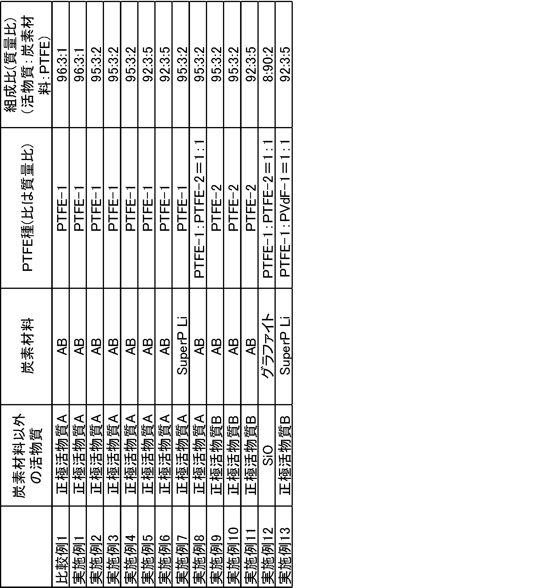
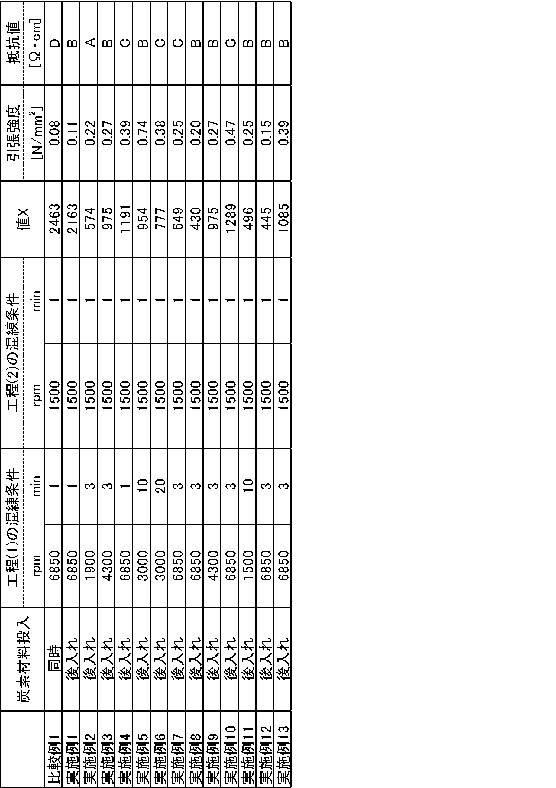
正極活物質A:Li(Ni0.6Mn0.2Co0.2)O2
正極活物質B:Li(Ni0.8Mn0.1Co0.1)O2
AB:Denka社製アセチレンブラックLi-100
SuperP Li:Imerys社製カーボンブラック
PVdF-1:アクリル酸官能基を有する変性PVdF(D50=2.0μm)
Claims (14)
- ポリテトラフルオロエチレンと、炭素材料と、前記炭素材料以外の電極活物質及び/又は前記ポリテトラフルオロエチレン以外のフッ素樹脂とを含み、
SEM-EDX分析によって得られる炭素組成分布の2000倍の視野の画像において、界面長/炭素検出量で示される値Xが2300以下である電極合剤シート。 - 値Xが300以上2000以下である請求項1記載の電極合剤シート。
- 前記電極合剤シートに対する前記ポリテトラフルオロエチレン及び前記ポリテトラフルオロエチレン以外のフッ素樹脂の合計含有量が0.1質量%以上10質量%以下である請求項1又は2記載の電極合剤シート。
- 前記炭素材料が導電助剤である請求項1~3のいずれかに記載の電極合剤シート。
- 前記炭素材料以外の電極活物質が正極活物質である請求項1~4のいずれかに記載の電極合剤シート。
- 前記正極活物質の含有量が前記電極合剤シートに対し、92%以上99質量%以下である請求項5記載の電極合剤シート。
- 請求項1~6のいずれかに記載の電極合剤シートを含む電極。
- 請求項7記載の電極を備える二次電池。
- ポリテトラフルオロエチレンと、炭素材料以外の電極活物質及び/又は前記ポリテトラフルオロエチレン以外のフッ素樹脂とを混合する工程(1)、及び、
工程(1)で得られた混合物と炭素材料とを混合する工程(2)
を含む電極合剤シートの製造方法。 - 工程(1)において、剪断力により前記ポリテトラフルオロエチレンのフィブリルを発生させる請求項9記載の製造方法。
- 工程(2)の混合を、工程(1)より低い剪断力により行う請求項9又は10記載の製造方法。
- 工程(1)で混合する成分がいずれも粉末であり、工程(1)が液体媒体の不存在下に実施される請求項9~11のいずれかに記載の製造方法。
- 工程(2)における処理温度が工程(1)における処理温度よりも低い請求項9~12のいずれかに記載の製造方法。
- 工程(1)と工程(2)は同一装置を用いて行われる請求項9~13のいずれかに記載の製造方法。
Priority Applications (4)
| Application Number | Priority Date | Filing Date | Title |
|---|---|---|---|
| EP24808833.8A EP4521482A4 (en) | 2023-06-13 | 2024-06-13 | Electrode mixture film, electrode, secondary battery and method for producing an electrode mixture film |
| KR1020257041441A KR20250179114A (ko) | 2023-06-13 | 2024-06-13 | 전극 합제 시트, 전극, 이차 전지 및 전극 합제 시트의 제조 방법 |
| CN202480039603.4A CN121311967A (zh) | 2023-06-13 | 2024-06-13 | 电极合剂片、电极、二次电池以及电极合剂片的制造方法 |
| US19/415,916 US20260100376A1 (en) | 2023-06-13 | 2025-12-11 | Electrode mixture sheet, electrode, secondary battery, and method for producing electrode mixture sheet |
Applications Claiming Priority (2)
| Application Number | Priority Date | Filing Date | Title |
|---|---|---|---|
| JP2023-097002 | 2023-06-13 | ||
| JP2023097002 | 2023-06-13 |
Related Child Applications (1)
| Application Number | Title | Priority Date | Filing Date |
|---|---|---|---|
| US19/415,916 Continuation US20260100376A1 (en) | 2023-06-13 | 2025-12-11 | Electrode mixture sheet, electrode, secondary battery, and method for producing electrode mixture sheet |
Publications (1)
| Publication Number | Publication Date |
|---|---|
| WO2024257832A1 true WO2024257832A1 (ja) | 2024-12-19 |
Family
ID=93852191
Family Applications (1)
| Application Number | Title | Priority Date | Filing Date |
|---|---|---|---|
| PCT/JP2024/021514 Ceased WO2024257832A1 (ja) | 2023-06-13 | 2024-06-13 | 電極合剤シート、電極、二次電池、及び、電極合剤シートの製造方法 |
Country Status (6)
| Country | Link |
|---|---|
| US (1) | US20260100376A1 (ja) |
| EP (1) | EP4521482A4 (ja) |
| JP (1) | JP7659216B2 (ja) |
| KR (1) | KR20250179114A (ja) |
| CN (1) | CN121311967A (ja) |
| WO (1) | WO2024257832A1 (ja) |
Citations (7)
| Publication number | Priority date | Publication date | Assignee | Title |
|---|---|---|---|---|
| JP2005527652A (ja) | 2002-01-04 | 2005-09-15 | イー・アイ・デュポン・ドウ・ヌムール・アンド・カンパニー | 濃縮フルオロポリマー分散液 |
| JP2010097817A (ja) * | 2008-10-16 | 2010-04-30 | Toyo Ink Mfg Co Ltd | リチウム二次電池用正極合剤ペースト |
| JP2014194927A (ja) * | 2013-02-26 | 2014-10-09 | Toyo Ink Sc Holdings Co Ltd | 合材スラリーおよびその製造方法とそれを用いた電極、電池 |
| JP2015532519A (ja) * | 2013-03-19 | 2015-11-09 | エルジー・ケム・リミテッド | 低抵抗電気化学素子用電極、その製造方法及び電極を含む電気化学素子 |
| WO2021045228A1 (ja) | 2019-09-05 | 2021-03-11 | ダイキン工業株式会社 | ポリテトラフルオロエチレン水性分散液 |
| KR20220093603A (ko) * | 2020-12-28 | 2022-07-05 | 주식회사 엘지에너지솔루션 | 이차전지용 프리 웨팅 건식 전극, 이의 제조방법, 및 이를 포함하는 이차전지 |
| WO2022163186A1 (ja) | 2021-01-27 | 2022-08-04 | パナソニックIpマネジメント株式会社 | 電極、及び電極の製造方法 |
Family Cites Families (2)
| Publication number | Priority date | Publication date | Assignee | Title |
|---|---|---|---|---|
| CN113937284B (zh) * | 2020-07-14 | 2023-09-22 | 华为技术有限公司 | 用于电池电极的薄膜及其制备方法 |
| WO2023054709A1 (ja) * | 2021-09-30 | 2023-04-06 | ダイキン工業株式会社 | ポリテトラフルオロエチレン粉末、電極用バインダー、電極合剤、電極、及び、二次電池 |
-
2024
- 2024-06-13 JP JP2024095891A patent/JP7659216B2/ja active Active
- 2024-06-13 CN CN202480039603.4A patent/CN121311967A/zh active Pending
- 2024-06-13 WO PCT/JP2024/021514 patent/WO2024257832A1/ja not_active Ceased
- 2024-06-13 KR KR1020257041441A patent/KR20250179114A/ko active Pending
- 2024-06-13 EP EP24808833.8A patent/EP4521482A4/en active Pending
-
2025
- 2025-12-11 US US19/415,916 patent/US20260100376A1/en active Pending
Patent Citations (7)
| Publication number | Priority date | Publication date | Assignee | Title |
|---|---|---|---|---|
| JP2005527652A (ja) | 2002-01-04 | 2005-09-15 | イー・アイ・デュポン・ドウ・ヌムール・アンド・カンパニー | 濃縮フルオロポリマー分散液 |
| JP2010097817A (ja) * | 2008-10-16 | 2010-04-30 | Toyo Ink Mfg Co Ltd | リチウム二次電池用正極合剤ペースト |
| JP2014194927A (ja) * | 2013-02-26 | 2014-10-09 | Toyo Ink Sc Holdings Co Ltd | 合材スラリーおよびその製造方法とそれを用いた電極、電池 |
| JP2015532519A (ja) * | 2013-03-19 | 2015-11-09 | エルジー・ケム・リミテッド | 低抵抗電気化学素子用電極、その製造方法及び電極を含む電気化学素子 |
| WO2021045228A1 (ja) | 2019-09-05 | 2021-03-11 | ダイキン工業株式会社 | ポリテトラフルオロエチレン水性分散液 |
| KR20220093603A (ko) * | 2020-12-28 | 2022-07-05 | 주식회사 엘지에너지솔루션 | 이차전지용 프리 웨팅 건식 전극, 이의 제조방법, 및 이를 포함하는 이차전지 |
| WO2022163186A1 (ja) | 2021-01-27 | 2022-08-04 | パナソニックIpマネジメント株式会社 | 電極、及び電極の製造方法 |
Non-Patent Citations (1)
| Title |
|---|
| See also references of EP4521482A4 |
Also Published As
| Publication number | Publication date |
|---|---|
| KR20250179114A (ko) | 2025-12-29 |
| JP2024178944A (ja) | 2024-12-25 |
| CN121311967A (zh) | 2026-01-09 |
| US20260100376A1 (en) | 2026-04-09 |
| EP4521482A1 (en) | 2025-03-12 |
| EP4521482A4 (en) | 2025-10-15 |
| JP7659216B2 (ja) | 2025-04-09 |
Similar Documents
| Publication | Publication Date | Title |
|---|---|---|
| JP7303470B2 (ja) | ポリテトラフルオロエチレン粉末、電極用バインダー、電極合剤、電極、及び、二次電池 | |
| JP7303468B2 (ja) | ポリテトラフルオロエチレン粉末、電極用バインダー、電極合剤、電極、及び、二次電池 | |
| JP7303469B2 (ja) | ポリテトラフルオロエチレン粉末、電極用バインダー、電極合剤、電極、及び、二次電池 | |
| US20250340683A1 (en) | Tetrafluoroethylene-based polymer, binder for electrochemical devices, electrode mixture, electrode, and secondary battery | |
| JP7653042B2 (ja) | テトラフルオロエチレン系ポリマー組成物、電気化学デバイス用バインダー、電極合剤、電極、及び、二次電池 | |
| JP7492186B1 (ja) | 電気化学デバイス用合剤、電気化学デバイス用合剤シート、電極、及び、電気化学デバイス | |
| JP2024111114A (ja) | 電気化学デバイス用バインダー用フッ素樹脂、電気化学デバイス用バインダー、電極合剤、電極、及び、二次電池 | |
| JP7659216B2 (ja) | 電極合剤シート、電極、二次電池、及び、電極合剤シートの製造方法 | |
| JP7684617B2 (ja) | 電気化学デバイス用合剤シート、電気化学デバイス、及び、電気化学デバイス用合剤シートの製造方法 | |
| JP7583341B2 (ja) | テトラフルオロエチレン系ポリマー組成物、電気化学デバイス用バインダー、電極合剤、電極、及び、二次電池 | |
| JP7583317B2 (ja) | 電気化学デバイス用バインダー用フッ素樹脂、電気化学デバイス用バインダー、電極合剤、電極、及び、二次電池 | |
| JP7684612B2 (ja) | テトラフルオロエチレン系ポリマー組成物、電気化学デバイス用バインダー、電極合剤、電極、及び、二次電池 | |
| JP7804214B2 (ja) | 電気化学デバイス用合剤、電気化学デバイス用合剤シート、電気化学デバイス、及び、電気化学デバイス用合剤シートの製造方法 | |
| WO2024154809A1 (ja) | フッ素系ポリマー組成物、電気化学デバイス用バインダー、電極合剤、電極、及び、二次電池 | |
| JP2024101797A (ja) | ポリテトラフルオロエチレン組成物、電池用バインダー、電極合剤、電極、及び、二次電池 |
Legal Events
| Date | Code | Title | Description |
|---|---|---|---|
| WWE | Wipo information: entry into national phase |
Ref document number: 2024808833 Country of ref document: EP |
|
| ENP | Entry into the national phase |
Ref document number: 2024808833 Country of ref document: EP Effective date: 20241127 |
|
| ENP | Entry into the national phase |
Ref document number: 1020257041441 Country of ref document: KR Free format text: ST27 STATUS EVENT CODE: A-0-1-A10-A15-NAP-PA0105 (AS PROVIDED BY THE NATIONAL OFFICE) |
|
| WWE | Wipo information: entry into national phase |
Ref document number: 1020257041441 Country of ref document: KR |
|
| WWP | Wipo information: published in national office |
Ref document number: 1020257041441 Country of ref document: KR |
|
| WWE | Wipo information: entry into national phase |
Ref document number: 202617000051 Country of ref document: IN |
|
| NENP | Non-entry into the national phase |
Ref country code: DE |
|
| WWP | Wipo information: published in national office |
Ref document number: 202617000051 Country of ref document: IN |