WO2024257851A1 - Gas barrier laminate and packaging - Google Patents
Gas barrier laminate and packaging Download PDFInfo
- Publication number
- WO2024257851A1 WO2024257851A1 PCT/JP2024/021651 JP2024021651W WO2024257851A1 WO 2024257851 A1 WO2024257851 A1 WO 2024257851A1 JP 2024021651 W JP2024021651 W JP 2024021651W WO 2024257851 A1 WO2024257851 A1 WO 2024257851A1
- Authority
- WO
- WIPO (PCT)
- Prior art keywords
- layer
- adhesive layer
- gas barrier
- adhesive
- substrate
- Prior art date
- Legal status (The legal status is an assumption and is not a legal conclusion. Google has not performed a legal analysis and makes no representation as to the accuracy of the status listed.)
- Ceased
Links
Images


Classifications
-
- B—PERFORMING OPERATIONS; TRANSPORTING
- B65—CONVEYING; PACKING; STORING; HANDLING THIN OR FILAMENTARY MATERIAL
- B65D—CONTAINERS FOR STORAGE OR TRANSPORT OF ARTICLES OR MATERIALS, e.g. BAGS, BARRELS, BOTTLES, BOXES, CANS, CARTONS, CRATES, DRUMS, JARS, TANKS, HOPPERS, FORWARDING CONTAINERS; ACCESSORIES, CLOSURES, OR FITTINGS THEREFOR; PACKAGING ELEMENTS; PACKAGES
- B65D65/00—Wrappers or flexible covers; Packaging materials of special type or form
- B65D65/38—Packaging materials of special type or form
- B65D65/40—Applications of laminates for particular packaging purposes
-
- B—PERFORMING OPERATIONS; TRANSPORTING
- B32—LAYERED PRODUCTS
- B32B—LAYERED PRODUCTS, i.e. PRODUCTS BUILT-UP OF STRATA OF FLAT OR NON-FLAT, e.g. CELLULAR OR HONEYCOMB, FORM
- B32B27/00—Layered products comprising a layer of synthetic resin
- B32B27/32—Layered products comprising a layer of synthetic resin comprising polyolefins
-
- B—PERFORMING OPERATIONS; TRANSPORTING
- B32—LAYERED PRODUCTS
- B32B—LAYERED PRODUCTS, i.e. PRODUCTS BUILT-UP OF STRATA OF FLAT OR NON-FLAT, e.g. CELLULAR OR HONEYCOMB, FORM
- B32B7/00—Layered products characterised by the relation between layers; Layered products characterised by the relative orientation of features between layers, or by the relative values of a measurable parameter between layers, i.e. products comprising layers having different physical, chemical or physicochemical properties; Layered products characterised by the interconnection of layers
- B32B7/02—Physical, chemical or physicochemical properties
- B32B7/022—Mechanical properties
Definitions
- This disclosure relates to a gas barrier laminate and a packaging bag.
- Patent Document 1 discloses a gas barrier laminate film that includes a resin substrate, a gas barrier deposition layer that is provided on the resin substrate and mainly contains an inorganic compound, and a gas barrier coating layer that is provided on the gas barrier deposition layer.
- the objective of one aspect of the present disclosure is to provide a gas barrier laminate and a packaging bag that can exhibit good gas barrier properties even after retort treatment.
- a gas barrier laminate is a gas barrier laminate comprising a barrier layer having a substrate on which a barrier coat is provided, a sealant layer overlying a first main surface of the barrier layer, a support layer overlying a second main surface of the barrier layer, a first adhesive layer bonding the barrier layer and the sealant layer, and a second adhesive layer bonding the barrier layer and the support layer, wherein the first adhesive layer contains a two-component curing urethane adhesive, the substrate contains polyolefin, and after performing a retort treatment on the gas barrier laminate, the elastic modulus of the first adhesive layer measured by a scanning probe microscope is 5 MPa or more and less than 53 MPa.
- the elastic modulus of the first adhesive layer measured with a scanning probe microscope (SPM) is 5 MPa or more and less than 53 MPa.
- SPM scanning probe microscope
- the second adhesive layer contains a two-component curing urethane adhesive, and the modulus of elasticity of the second adhesive layer measured with a scanning probe microscope after retort treatment may be 5 MPa or more and less than 53 MPa. In this case, even if the substrate and support layer expand and contract due to retort treatment, the second adhesive layer follows suit well. This makes it possible to suppress damage to the barrier coat due to cracks occurring in the second adhesive layer.
- the barrier layer may further have an anchor coat layer and a deposition layer located between the substrate and the barrier coat, and the anchor coat layer may be located between the substrate and the deposition layer.
- the gas barrier properties of the gas barrier laminate can be improved.
- the thickness of the deposition layer may be 5 nm or more and 80 nm or less. In this case, the gas barrier properties can be improved while preventing cracks in the deposition layer.
- the elastic modulus of the first adhesive layer measured with a scanning probe microscope may be 55 MPa or more.
- the thickness of the first adhesive layer and the thickness of the second adhesive layer may each be 0.5 ⁇ m or more and 10 ⁇ m or less.
- the gas barrier laminate can be easily made into a mono-material while effectively suppressing peeling between the barrier layer and the sealant layer.
- the elastic modulus of the sealant may be 600 MPa or more and 1400 MPa or less. In this case, the moldability of the gas barrier laminate may be improved.
- the substrate and the sealant layer are each a polyolefin film, and the total mass ratio of polyolefin in the gas barrier laminate may be 90 mass% or more. In this case, a mono-material structure is realized.
- the substrate is a stretched polypropylene film
- the sealant layer may be a non-stretched polypropylene film.
- the laminate has excellent heat resistance against retort treatment, etc.
- One aspect of the present disclosure may provide a packaging bag that is a bag made from the gas barrier laminate.
- This disclosure provides a gas barrier laminate and packaging bag that can exhibit good gas barrier properties even after retort processing.
- FIG. 1 is a schematic plan view of a laminate according to one embodiment.
- FIG. 2 is a schematic cross-sectional view showing a laminate according to one embodiment.
- FIG. 3 is a schematic front view of an example of a packaging bag.
- FIG. 4 is a schematic diagram showing a method for measuring the thermal shrinkage rate during heating in an oven.
- Fig. 1 is a schematic plan view of a laminate according to an embodiment.
- Fig. 2 is a schematic cross-sectional view of a laminate according to an embodiment.
- the laminate 1 shown in Figs. 1 and 2 is a sheet-like member (gas barrier laminate) having gas barrier properties, and is, for example, a sheet-like packaging material used in the manufacture of packaging bags and the like.
- the laminate 1 can be suitably used in applications in which a heat treatment such as a retort treatment or a boiling treatment is performed.
- Retort processing is a method of sterilizing microorganisms such as mold, yeast, and bacteria under pressure, generally for the preservation of food, medicine, etc. Normally, the packaging bag containing the food, etc. is sterilized under pressure at 105-140°C, 0.15-0.30 MPa for 10-120 minutes. There are two types of retort equipment: steam type, which uses heated steam, and hot water type, which uses pressurized heated water, and the appropriate type is used depending on the sterilization conditions of the food, etc. that will be contained. Boiling processing is a method of sterilizing food, medicine, etc. by moist heat to preserve it. Normally, depending on the contents, the packaging bag containing the food, etc.
- Boiling processing is usually performed using a hot water bath at 100°C or less.
- a batch type in which the food is immersed in a hot water bath at a constant temperature for a certain period of time and then removed
- a continuous type in which the food is passed through a tunnel-type hot water bath for processing.
- the laminate 1 has a barrier layer 10, a sealant layer 20, a first adhesive layer 30, a support layer 40, and a second adhesive layer 50.
- the sealant layer 20, the first adhesive layer 30, the barrier layer 10, the second adhesive layer 50, and the support layer 40 are laminated in this order.
- the direction MD is defined as the flow direction (longitudinal direction) of the laminate 1
- the direction TD is defined as the width direction (short direction) of the laminate 1.
- the direction perpendicular to both directions MD and TD is defined as the stacking direction of the members included in the laminate 1.
- the barrier layer 10 is a member that functions as an intermediate layer in the laminate 1, and exhibits gas barrier properties against gases such as water vapor and oxygen. As shown in FIG. 2, the barrier layer 10 has a substrate 11, an adhesion layer 12, a deposition layer 13, and a barrier coat 14. In the barrier layer 10, the substrate 11, the adhesion layer 12, the deposition layer 13, and the barrier coat 14 are laminated in this order. Therefore, the adhesion layer 12 and the deposition layer 13 are located between the substrate 11 and the barrier coat 14 in the stacking direction, and the adhesion layer 12 is located between the substrate 11 and the deposition layer 13. In this embodiment, the substrate 11 of the barrier layer 10 is closest to the first adhesive layer 30 in the stacking direction and forms the first main surface 10b of the barrier layer 10. Therefore, the barrier coat 14 of the barrier layer 10 is farthest from the first adhesive layer 30 in the stacking direction and forms the second main surface 10a of the barrier layer 10.
- the substrate 11 is a plastic member that functions as a support layer in the laminate 1.
- the thickness of the substrate 11 is not particularly limited. Depending on the application, the thickness can be 6 to 200 ⁇ m, but from the viewpoint of reducing materials to reduce the environmental load and from the viewpoint of obtaining excellent heat resistance, impact resistance, and excellent gas barrier properties, the thickness may be 9 to 50 ⁇ m, 12 to 38 ⁇ m, or 18 to 30 ⁇ m.
- the substrate 11 is, for example, a polyolefin film.
- the substrate 11 may include a polypropylene film or may be made of a polypropylene film.
- the polypropylene film may be an acid-modified polypropylene film obtained by graft-modifying polypropylene with an unsaturated carboxylic acid, an acid anhydride of an unsaturated carboxylic acid, an ester of an unsaturated carboxylic acid, or the like.
- polypropylene-based resins such as homopolypropylene resin (PP), propylene-ethylene random copolymer, propylene-ethylene block copolymer, and propylene- ⁇ -olefin copolymer can be used.
- PP homopolypropylene resin
- propylene-ethylene random copolymer propylene-ethylene random copolymer
- propylene-ethylene block copolymer propylene-ethylene block copolymer
- propylene- ⁇ -olefin copolymer propylene- ⁇ -olefin copolymer
- the polypropylene film constituting the substrate 11 may contain various additives such as flame retardants, slip agents, antiblocking agents, antioxidants, light stabilizers, tackifiers, and antistatic agents.
- the polypropylene film constituting the substrate 11 may be a stretched film or a non-stretched film. From the viewpoints of impact resistance, heat resistance, water resistance, dimensional stability, etc., the polypropylene film may be a stretched polypropylene film. This can prevent the substrate 11 from thermally fusing during the heat sealing process during bag production.
- the laminate 1 may also be used in applications where a heat treatment such as a retort treatment or boiling treatment is performed.
- the stretching method is not particularly limited, and any method may be used as long as a dimensionally stable film can be supplied, such as stretching by inflation, uniaxial stretching, or biaxial stretching.
- the laminated surface of the substrate 11 may be subjected to various pretreatments such as corona treatment, plasma treatment, and frame treatment, or may be provided with a coating layer such as an easy-adhesion layer, as long as the barrier performance is not impaired.
- the laminated surface may be the surface that forms the first main surface 10b of the barrier layer 10.
- the heat shrinkage rate in the MD direction of the substrate 11 calculated by the following formula (1) is 1% or more.
- the heat shrinkage rate in the MD direction of the substrate 11 calculated by the following formula (1) is 1% or more.
- the heat shrinkage rate in the MD direction is, for example, 12% or less, 11% or less, 10% or less, 9% or less, 8% or less, 7% or less, etc.
- the heat shrinkage rate in the MD direction is 1.2% or more, 1.5% or more, 2% or more, 2.5% or more, 3% or more, etc.
- the heat shrinkage rate in the MD direction is, for example, 1% to 7%, 1% to 6.7%, 1.5% to 4%, 2% to 3.7%, etc.
- the heat shrinkage rate of a biaxially oriented polypropylene film is 1%, whereas the heat shrinkage rate of a PET film is less than 1%.
- Heat shrinkage rate in MD direction (%) (MD length before heating - MD length after heating) / MD length before heating ⁇ 100 ... (1)
- the heat shrinkage rate in the TD direction of the substrate 11 calculated by the following formula (2) is not particularly limited, but is, for example, 1% or more and is equal to or less than the heat shrinkage rate in the MD direction of the substrate 11.
- the heat shrinkage rate in the TD direction is, for example, 12% or less, 11% or less, 10% or less, 9% or less, 8% or less, 7% or less, etc.
- the heat shrinkage rate in the TD direction is 1.2% or more, 1.5% or more, 2% or more, 2.5% or more, 3% or more, etc.
- the heat shrinkage rate in the TD direction is, for example, 1% or more and 7% or less, 1% or more and 6.7% or less, 1.5% or more and 4% or less, 2% or more and 3.7% or less, etc.
- Thermal shrinkage rate in the TD direction (%) (TD length before heating - TD length after heating) / TD length before heating ⁇ 100 ...
- the heat shrinkage rate in the MD direction is greater than the heat shrinkage rate in the TD direction.
- the adhesion layer 12 functions as a layer (anchor coat layer) capable of improving the adhesion performance of the deposition layer 13 on the substrate 11, and is provided directly on the substrate 11. For this reason, the adhesion layer 12 is located between the substrate 11 and the deposition layer 13.
- the smoothness of the surface of the barrier layer 10 on which the deposition layer 13 is provided can be improved. Note that improved smoothness makes it easier to form the deposition layer 13 uniformly without defects, and makes it easier to exhibit high barrier properties.
- the adhesion layer 12 can be formed, for example, using an anchor coat agent.
- anchor coating agents include polyester-based polyurethane resins and polyether-based polyurethane resins. From the viewpoints of heat resistance and interlayer adhesive strength, polyester-based polyurethane resins may be used as the anchor coating agent.
- the thickness of the adhesive layer 12 is not particularly limited, but may be in the range of 0.01 to 5 ⁇ m, 0.03 to 3 ⁇ m, or 0.05 to 2 ⁇ m. If the thickness of the adhesive layer 12 is equal to or greater than the lower limit, there is a tendency for more sufficient interlayer adhesive strength to be obtained, whereas if the thickness is equal to or less than the upper limit, there is a tendency for the desired gas barrier properties to be easily achieved.
- the method for applying the adhesive layer 12 onto the substrate 11 can be any known application method without particular limitation, and examples of such methods include immersion (dipping), spraying, coater, printing machine, brushing, etc.
- examples of the types of coaters and printing machines used in these methods and the application methods thereof include gravure coaters such as direct gravure, reverse gravure, kiss reverse gravure, and offset gravure, reverse roll coaters, microgravure coaters, coaters combined with chamber doctor, air knife coaters, dip coaters, bar coaters, comma coaters, die coaters, etc.
- the coating amount of the adhesion layer 12 may be 0.01 to 5 g/ m2 or 0.03 to 3 g/ m2 in terms of the mass per m2 after the anchor coating agent is applied and dried. If the mass per m2 after the anchor coating agent is applied and dried is equal to or greater than the lower limit, the film tends to be sufficiently formed, whereas if it is equal to or less than the upper limit, the film tends to be sufficiently dried and the solvent tends not to remain.
- the method for drying the adhesion layer 12 is not particularly limited, but examples include natural drying, drying in an oven set at a predetermined temperature, and using a dryer attached to the coater, such as an arch dryer, floating dryer, drum dryer, or infrared dryer. Furthermore, the drying conditions can be appropriately selected depending on the drying method. For example, in the method of drying in an oven, drying may be performed at a temperature of 60 to 100°C for about 1 second to 2 minutes.
- a polyvinyl alcohol resin can be used as the adhesive layer 12.
- the polyvinyl alcohol resin may be any resin that has vinyl alcohol units formed by saponifying vinyl ester units, such as polyvinyl alcohol (PVA) and ethylene-vinyl alcohol copolymer (EVOH).
- PVA examples include resins obtained by polymerizing vinyl esters such as vinyl acetate, vinyl formate, vinyl propionate, vinyl valerate, vinyl caprate, vinyl laurate, vinyl stearate, vinyl pivalate, and vinyl versatate alone and then saponifying them.
- the PVA may be a modified PVA that has been copolymerized or post-modified. Modified PVA can be obtained, for example, by copolymerizing a vinyl ester with an unsaturated monomer that is copolymerizable with the vinyl ester and then saponifying it.
- unsaturated monomers copolymerizable with vinyl esters include olefins such as ethylene, propylene, isobutylene, ⁇ -octene, ⁇ -dodecene, and ⁇ -octadecene; hydroxyl group-containing ⁇ -olefins such as 3-buten-1-ol, 4-pentyn-1-ol, and 5-hexen-1-ol; unsaturated acids such as acrylic acid, methacrylic acid, crotonic acid, maleic acid, maleic anhydride, itaconic acid, and undecylenic acid; nitriles such as acrylonitrile and methacrylonitrile; diacetone acrylamide, acrylic Amides such as amide and methacrylamide; olefin sulfonic acids such as ethylene sulfonic acid, allyl sulfonic acid, and methallyl sulfonic acid; vinyl compounds such as alkyl vinyl ether, di
- the degree of polymerization of PVA is, for example, 300 to 3000. If the degree of polymerization is less than 300, the barrier properties are likely to decrease, and if it exceeds 3000, the viscosity is too high and the coating suitability is likely to decrease.
- the degree of saponification of PVA may be 90 mol% or more, 95 mol% or more, or 99 mol% or more.
- the degree of saponification of PVA may be 100 mol% or less, or 99.9 mol% or less.
- the degree of polymerization and degree of saponification of PVA can be measured in accordance with the method described in JIS K 6726 (1994).
- EVOH is generally obtained by saponifying copolymers of ethylene and vinyl esters such as vinyl acetate, vinyl formate, vinyl propionate, vinyl valerate, vinyl caprate, vinyl laurate, vinyl stearate, vinyl pivalate, and vinyl versatate.
- EVOH has a degree of polymerization of, for example, 300 to 3000. If the degree of polymerization is less than 300, the barrier properties tend to decrease, while if it exceeds 3000, the viscosity is too high and the coating suitability tends to decrease.
- the degree of saponification of the vinyl ester component of EVOH may be 90 mol% or more, 95 mol% or more, or 99 mol% or more.
- the degree of saponification of EVOH may be 100 mol% or less, or 99.9 mol% or less.
- the degree of saponification of EVOH is determined by nuclear magnetic resonance (1H-NMR) measurement, from the peak area of the hydrogen atoms contained in the vinyl ester structure and the peak area of the hydrogen atoms contained in the vinyl alcohol structure.
- the ethylene unit content of EVOH is 10 mol% or more, more preferably 15 mol% or more, even more preferably 20 mol% or more, and particularly preferably 25 mol% or more.
- the ethylene unit content of EVOH is preferably 65 mol% or less, more preferably 55 mol% or less, and even more preferably 50 mol% or less.
- the gas barrier properties or dimensional stability can be maintained well under high humidity.
- the gas barrier properties can be improved.
- the ethylene unit content of EVOH can be determined by the NMR method.
- adhesion layer 12 When a polyvinyl alcohol resin is used as the adhesion layer 12, methods for forming the adhesion layer 12 include coating with a polyvinyl alcohol resin solution, multi-layer extrusion, etc.
- the deposition layer 13 is a layer (gas barrier layer) that exhibits gas barrier properties against water vapor and oxygen, and contains at least one of a metal and an inorganic oxide.
- the deposition layer 13 is provided directly on the adhesive layer 12.
- the deposition layer 13 may have a single layer structure or a laminated structure. Therefore, the deposition layer 13 contains at least one of a metal deposition layer and an inorganic oxide layer.
- examples of the metal contained in the metal deposition layer include aluminum and stainless steel.
- examples of the inorganic oxide contained in the inorganic oxide layer include aluminum oxide, silicon oxide, magnesium oxide, and tin oxide.
- the inorganic oxide may be selected from the group consisting of aluminum oxide, silicon oxide, and magnesium oxide.
- the inorganic oxide layer may contain a layer using silicon oxide.
- the O/Si ratio of the inorganic oxide layer is preferably 1.7 or more.
- the O/Si ratio is 1.7 or more, the content of metal Si is suppressed, and good transparency is easily obtained.
- the O/Si ratio is preferably 2.0 or less.
- the crystallinity of SiO is high, and the inorganic oxide layer can be prevented from becoming too hard, and good tensile resistance can be obtained. This makes it possible to suppress the occurrence of cracks in the inorganic oxide layer when the barrier coat 14 is laminated.
- the substrate 11 may shrink due to heat during boiling or retort treatment, but when the O/Si ratio is 2.0 or less, the inorganic oxide layer easily follows the above shrinkage, and the deterioration of the barrier property can be suppressed.
- the O/Si ratio of the inorganic oxide layer is preferably 1.75 to 1.9, and more preferably 1.8 to 1.85.
- the O/Si ratio of the inorganic oxide layer can be determined by X-ray photoelectron spectroscopy (XPS).
- XPS X-ray photoelectron spectroscopy
- the measurement device is an X-ray photoelectron spectrometer (manufactured by JEOL Ltd., product name: JPS-90MXV)
- the X-ray source is non-monochromated MgK ⁇ (1253.6 eV)
- the measurement can be performed with an X-ray output of 100 W (10 kV-10 mA).
- relative sensitivity factors of 2.28 for O1s and 0.9 for Si2p can be used.
- the thickness of the deposition layer 13 is, for example, 5 nm or more and 80 nm or less. If the thickness of the deposition layer 13 is 5 nm or more, sufficient water vapor barrier properties can be obtained. Furthermore, if the thickness of the deposition layer 13 is 80 nm or less, the occurrence of cracks due to deformation caused by internal stress in the thin film can be suppressed, and a decrease in water vapor barrier properties can be suppressed. Note that if the thickness of the deposition layer 13 exceeds 80 nm, costs tend to increase due to an increase in the amount of material used and a longer film formation time, and this is not preferable from an economic standpoint. From the same standpoint as above, the thickness of the deposition layer 13 may be 20 nm or more and 40 nm or less.
- the deposition layer 13 can be formed, for example, by vacuum deposition.
- vacuum deposition physical vapor deposition or chemical vapor deposition can be used.
- physical vapor deposition include, but are not limited to, vacuum deposition, sputtering, and ion plating.
- chemical vapor deposition include, but are not limited to, thermal CVD, plasma CVD, and photo CVD.
- the resistive heating vacuum deposition method the EB (Electron Beam) heating vacuum deposition method, the induction heating vacuum deposition method, the sputtering method, the reactive sputtering method, the dual magnetron sputtering method, the plasma enhanced chemical vapor deposition method (PECVD method), etc. are particularly preferably used.
- the vacuum deposition method is currently the most superior.
- any of the following methods may be used: the electron beam heating method, the resistive heating method, or the induction heating method.
- the barrier coat 14 is a coating layer having gas barrier properties (gas barrier coating layer) and is provided on the substrate 11.
- the barrier coat 14 is a layer formed using a composition for forming a gas barrier coating layer (hereinafter also referred to as a coating agent) containing at least one selected from the group consisting of a hydroxyl group-containing polymer compound, a metal alkoxide, a silane coupling agent, and hydrolysates thereof, for example.
- the coating agent preferably contains at least a silane coupling agent or a hydrolysate thereof, more preferably contains at least one selected from the group consisting of a hydroxyl-containing polymer compound, a metal alkoxide, and their hydrolysates, and a silane coupling agent or a hydrolysate thereof, and even more preferably contains a hydroxyl-containing polymer compound or a hydrolysate thereof, a metal alkoxide or a hydrolysate thereof, and a silane coupling agent or a hydrolysate thereof.
- the coating agent can be prepared, for example, by mixing a metal alkoxide and a silane coupling agent directly, or after having been previously hydrolyzed, with a solution in which a hydroxyl-containing polymer compound, which is a water-soluble polymer, is dissolved in an aqueous solvent (water or a water/alcohol mixture).
- hydroxyl-containing polymeric compounds used in the coating agent include polyvinyl alcohol, polyvinylpyrrolidone, starch, methyl cellulose, carboxymethyl cellulose, and sodium alginate.
- polyvinyl alcohol (PVA) is preferred when used in the coating agent for the barrier coat 14, as it has particularly excellent gas barrier properties.
- the barrier coat 14 is preferably formed from a composition containing at least one selected from the group consisting of metal alkoxides represented by the following general formula (I) and their hydrolysates.
- M(OR 1 ) m (R 2 ) nm ...(I) R1 and R2 are each independently a monovalent organic group having 1 to 8 carbon atoms, and are preferably an alkyl group such as a methyl group or an ethyl group.
- M represents an n-valent metal atom such as Si, Ti, Al, or Zr.
- m is an integer from 1 to n.
- the R1s or R2s may be the same or different.
- metal alkoxides include tetraethoxysilane [Si(OC 2 H 5 ) 4 ], triisopropoxyaluminum [Al(O-2′-C 3 H 7 ) 3 ], etc. Tetraethoxysilane and triisopropoxyaluminum are preferred because they are relatively stable in aqueous solvents after hydrolysis.
- the silane coupling agent includes a compound represented by the following general formula (II). Si(OR 11 ) p (R 12 ) 3-p R 13 ...(II)
- R 11 represents an alkyl group such as a methyl group or an ethyl group
- R 12 represents a monovalent organic group such as an alkyl group, an aralkyl group, an aryl group, an alkenyl group, an alkyl group substituted with an acryloxy group, or an alkyl group substituted with a methacryloxy group
- R 13 represents a monovalent organic functional group
- p represents an integer of 1 to 3.
- the R 11s or the R 12s may be the same or different.
- the monovalent organic functional group represented by R 13 include a monovalent organic functional group containing a glycidyloxy group, an epoxy group, a mercapto group, a hydroxyl group, an amino group, an alkyl group substituted with a halogen atom, or an isocyanate group.
- silane coupling agents include vinyltrimethoxysilane, ⁇ -chloropropylmethyldimethoxysilane, ⁇ -chloropropyltrimethoxysilane, glycidoxypropyltrimethoxysilane, ⁇ -methacryloxypropyltrimethoxysilane, and ⁇ -methacryloxypropylmethyldimethoxysilane.
- the silane coupling agent may also be a polymer formed by polymerization of the compound represented by the above general formula (II).
- a trimer is preferred, and 1,3,5-tris(3-trialkoxysilylalkyl)isocyanurate is more preferred.
- This is a condensation polymer of 3-isocyanate alkylalkoxysilane. It is known that this 1,3,5-tris(3-trialkoxysilylalkyl)isocyanurate has no chemical reactivity in the isocyanate portion, but the reactivity is ensured by the polarity of the nurate portion.
- 3-isocyanate alkyl alkoxysilanes are highly reactive and have low liquid stability, whereas 1,3,5-tris (3-trialkoxysilyl alkyl) isocyanurates are not water-soluble due to the polarity of the nurate moiety, but are easily dispersed in aqueous solutions and can maintain a stable liquid viscosity.
- the water resistance of 3-isocyanate alkyl alkoxysilanes is equivalent to that of 1,3,5-tris (3-trialkoxysilyl alkyl) isocyanurates.
- 1,3,5-tris(3-trialkoxysilylalkyl)isocyanurates are produced by thermal condensation of 3-isocyanatepropylalkoxysilane, and may contain the raw material 3-isocyanatepropylalkoxysilane, but this does not pose any particular problems. More preferred is 1,3,5-tris(3-trialkoxysilylpropyl)isocyanurate, and even more preferred is 1,3,5-tris(3-trimethoxysilylpropyl)isocyanurate.
- This methoxy group has a fast hydrolysis rate, and those containing propyl groups are relatively inexpensive, so 1,3,5-tris(3-trimethoxysilylpropyl)isocyanurate is advantageous in practical use.
- additives such as isocyanate compounds, dispersants, stabilizers, viscosity adjusters, and colorants can be added to the coating agent as needed, provided that the gas barrier properties are not impaired.
- the thickness of the barrier coat 14 may be 50 to 1000 nm, or 100 to 500 nm. If the thickness of the barrier coat 14 is 50 nm or more, there is a tendency for more sufficient gas barrier properties to be obtained, and if it is 1000 nm or less, there is a tendency for sufficient flexibility to be maintained.
- the coating liquid for forming the barrier coat 14 can be applied by, for example, dipping, roll coating, gravure coating, reverse gravure coating, air knife coating, comma coating, die coating, screen printing, spray coating, gravure offset, etc.
- the coating film obtained by applying this coating liquid can be dried by, for example, hot air drying, hot roll drying, high frequency irradiation, infrared irradiation, UV irradiation, or a combination of these.
- the temperature at which the coating film is dried may be, for example, 50 to 150°C or 70 to 100°C.
- the barrier coat 14 may be formed using a coating agent containing a polyvinyl alcohol resin and a silane compound. If necessary, an acid catalyst, an alkali catalyst, a photopolymerization initiator, etc. may be added to the coating agent.
- the polyvinyl alcohol resin is as described above.
- silane compounds include silane coupling agents, polysilazanes, and siloxanes, and more specifically, tetramethoxysilane, tetraethoxysilane, glycidoxypropyltrimethoxysilane, acryloxypropyltrimethoxysilane, and hexamethyldisilazane.
- the laminate 1 may include a printing layer.
- the printing layer can be provided, for example, on at least one surface of the substrate 11.
- the printing layer is provided at a position visible from the outside of the laminate 1 for the purpose of displaying information about the contents, identifying the contents, improving concealment, or improving the design of the packaging bag.
- the printing method and printing ink are not particularly limited, and are appropriately selected from known printing methods and printing inks in consideration of printability on the film, design such as color tone, adhesion, safety as a food container, and the like. Examples of printing methods that can be used include gravure printing, offset printing, gravure offset printing, flexographic printing, and inkjet printing. Among them, gravure printing can be preferably used from the viewpoints of productivity and high definition of the pattern.
- the surface of the layer on which the printing layer is to be formed may be subjected to various pretreatments such as corona treatment, plasma treatment, and frame treatment, or a coating layer such as an easy-adhesion layer may be formed.
- the sealant layer 20 is a layer that imparts heat-sealing sealability to the laminate 1, and overlaps the first main surface 10b of the barrier layer 10. From the viewpoint of recycling suitability of the laminate 1, the sealant layer 20 is a polyolefin film similar to the substrate 11.
- the sealant layer 20 has a single-layer structure and is a resin layer mainly made of polypropylene, but is not limited thereto.
- the sealant layer 20 may have a laminate structure.
- the sealant layer 20 may include a polypropylene film or may be made of a polypropylene film.
- the polypropylene film may be an acid-modified polypropylene film obtained by graft-modifying polypropylene with an unsaturated carboxylic acid, an acid anhydride of an unsaturated carboxylic acid, an ester of an unsaturated carboxylic acid, or the like.
- a polypropylene-based resin such as homopolypropylene resin (PP), propylene-ethylene random copolymer (random PP), propylene-ethylene block copolymer (block PP), propylene- ⁇ -olefin copolymer, or the like may be used.
- the sealant layer 20 has at least one of a layer containing homopropylene resin, a layer containing random PP, a layer containing block PP, and a layer containing propylene- ⁇ -olefin copolymer.
- a layer containing block PP may be used as an intermediate layer of the sealant layer 20.
- an elastomer may be added to the intermediate layer.
- the amount of elastomer added is, for example, 10% by mass or more and 30% by mass or less.
- a layer containing random PP may constitute the front and back surfaces of the sealant layer 20.
- the polypropylene film constituting the sealant layer 20 may be a non-oriented polypropylene film in order to improve the sealing performance by heat sealing.
- the polypropylene film constituting the sealant layer 20 may contain various additives such as flame retardants, slip agents, antiblocking agents, antioxidants, light stabilizers, tackifiers, and antistatic agents.
- the thickness of the sealant layer 20 is determined by the weight of the contents, the shape of the packaging bag, etc., but may be approximately 30 to 150 ⁇ m, or 50 to 80 ⁇ m.
- the elastic modulus of the sealant layer is, for example, 600 MPa or more, 700 MPa or more, 850 MPa or more, etc.
- the elastic modulus of the sealant layer 20 along the MD direction of the substrate 11 and the elastic modulus of the sealant layer 20 along the TD direction of the substrate 11 are, for example, 600 MPa or more.
- the elastic modulus of the sealant layer 20 along the MD direction of the substrate 11 is 850 MPa or more
- the elastic modulus of the sealant layer 20 along the TD direction of the substrate 11 is 700 MPa or more.
- the elastic modulus of the sealant layer is, for example, 1400 MPa or less, 1100 MPa or less, 1000 MPa or less, etc.
- the elastic modulus of the sealant layer 20 along the MD direction of the substrate 11 is 1100 MPa or less, and the elastic modulus of the sealant layer 20 along the TD direction of the substrate 11 is 1000 MPa or less.
- the elastic modulus of the sealant layer is 600 MPa or more and 1400 MPa or less.
- the elastic modulus of the sealant layer 20 is calculated from the stress measured when a 20 mm square sample of the sealant layer 20 is stretched by 0.05% to 0.25% under the conditions of a gauge length of 250 mm and a tensile speed of 5 m/min.
- the openability of the packaging bag corresponds to the ease of opening the bag. When the openingability of the packaging bag is good, the packaging bag is less likely to fail when filling the contents.
- the sealant layer 20 can be formed by any of the known lamination methods, including the dry lamination method in which the film-like sealant layer made of the above-mentioned polypropylene is bonded with an adhesive such as a one-component curing or two-component curing urethane adhesive, the non-solvent dry lamination method in which the film-like sealant layer is bonded with a solvent-free adhesive, and the extrusion lamination method in which the above-mentioned polypropylene is heated and melted, extruded into a curtain shape, and bonded together.
- an adhesive such as a one-component curing or two-component curing urethane adhesive
- the non-solvent dry lamination method in which the film-like sealant layer is bonded with a solvent-free adhesive
- extrusion lamination method in which the above-mentioned polypropylene is heated and melted, extruded into a curtain shape, and bonded together.
- the dry lamination method is preferred because it has high resistance to retort treatment, especially high-temperature hot water treatment at 120°C or higher.
- the packaging bag is to be used for an application in which it will be treated at a temperature of 85°C or lower, there are no particular limitations on the lamination method.
- the first adhesive layer 30 is a layered member that bonds the barrier layer 10 and the sealant layer 20.
- polyester-isocyanate resin, urethane resin, polyether resin, etc. can be used as the adhesive material contained in the first adhesive layer 30.
- a urethane resin that is resistant to retort (for example, a two-component curing urethane adhesive) may be used as the first adhesive layer 30.
- the adhesive may not contain 3-glycidyloxypropyltrimethoxysilane (GPTMS).
- the first adhesive layer 30 may not contain chlorine. In this case, the adhesive forming the first adhesive layer 30 can suppress coloring of the recycled resin after recycling and the generation of odor due to heat treatment.
- the first adhesive layer 30 may be formed of a biomass material and may not contain a solvent.
- the urethane adhesive is formed from a base agent and a curing agent.
- the base agent is, for example, polyester polyol, polyester polyurethane polyol, etc.
- the polyester polyol is obtained, for example, by polymerizing a diol and a dicarboxylic acid.
- the polyester polyurethane polyol is obtained, for example, by polymerizing a diol, a dicarboxylic acid, and a diisocyanate.
- the diol is, for example, ethylene glycol, neopentyl glycol, 1,6-hexanediol, 2,4-hexylene glycol, etc.
- the dicarboxylic acid is, for example, adipic acid, sebacic acid, isophthalic acid, terephthalic acid, etc.
- the diisocyanate is, for example, isophorone diisocyanate (hereinafter referred to as IPDI).
- the curing agent examples include an adduct of IPDI with trimethylolpropane (hereinafter referred to as TMP), an adduct of xylylene diisocyanate (hereinafter referred to as XDI) with TMP, a mixture of an adduct of IPDI with TMP and an adduct of XDI with TMP, and a biuret of hexamethylene diisocyanate (hereinafter referred to as HDI).
- TMP trimethylolpropane
- XDI xylylene diisocyanate
- HDI biuret of hexamethylene diisocyanate
- Mw weight-average molecular weight of the urethane adhesive is not particularly limited, but is, for example, about 10,000 to 50,000.
- the thickness of the first adhesive layer 30 is 0.5 ⁇ m or more and 10 ⁇ m or less. When the thickness of the first adhesive layer 30 is 0.5 ⁇ m or more, peeling between the barrier layer 10 and the sealant layer 20 can be effectively suppressed. When the thickness of the first adhesive layer 30 is 10 ⁇ m or less, the laminate 1 can be easily made into a mono-material (details will be described later).
- the thickness of the first adhesive layer 30 may be 1 ⁇ m or more, 2 ⁇ m or more, 8 ⁇ m or less, 6 ⁇ m or less, or 5 ⁇ m or less.
- the elastic modulus of first adhesive layer 30 is 5 MPa or more and less than 53 MPa.
- the first adhesive layer 30 can well follow the expansion and contraction of the base material 11 accompanying a heating treatment such as a retort treatment or a boiling treatment. Therefore, even if the above-mentioned heating treatment is performed on the laminate 1 including the base material 11 having the above-mentioned thermal shrinkage rate, peeling between the barrier layer 10 and the sealant layer 20 is unlikely to occur.
- the elastic modulus of the first adhesive layer 30 after the retort treatment may be, for example, 9 MPa or more, 15 MPa or more, 20 MPa or more, 50 MPa or less, 47 MPa or less, or 42 MPa or less.
- the elastic modulus of the first adhesive layer 30 before the retort treatment of the laminate 1 is not particularly limited, but is, for example, 55 MPa or more, or 60 MPa or more.
- the elastic modulus of the first adhesive layer 30 in the laminate 1 can be obtained, for example, by measuring the elastic modulus of a cross section of the portion (exposed portion) exposed from the sealant layer 20.
- the elastic modulus of the cross section can be obtained, for example, by measurement with a scanning probe microscope (SPM).
- the elastic modulus of the first adhesive layer 30 represents the elastic modulus calculated from a force curve measured with a scanning probe microscope (SPM).
- the elastic modulus of the first adhesive layer 30 can be obtained, for example, by the method described in the following examples.
- the elastic modulus of the first adhesive layer 30 that has not been subjected to retort treatment can also be obtained by the method described in the following examples.
- the hardness of the adhesive layer can be controlled by the adhesive material, the amount of hardener, the aging time, etc.
- the narrower the distance between the molecular chains of the adhesive the harder the adhesive layer tends to be.
- the bulkier the adhesive the softer the adhesive layer tends to be.
- An aliphatic adhesive layer tends to be softer than an alicyclic or aromatic adhesive layer.
- An alicyclic adhesive layer tends to be harder than an aromatic adhesive layer.
- the more hardener contained in the adhesive layer the harder the adhesive layer tends to be.
- the harder the adhesive layer the higher its elastic modulus.
- the support layer 40 is a sheet-like plastic member that functions as a support in the laminate 1.
- the support layer 40 may have the same function and performance as the substrate 11.
- the thickness of the support layer 40 may be approximately the same as the thickness of the substrate 11.
- the support layer 40 is, for example, a polyolefin film.
- the support layer 40 may include a polypropylene film or may be made of a polypropylene film.
- Various additives such as a flame retardant, a slip agent, an antiblocking agent, an antioxidant, a light stabilizer, a tackifier, and an antistatic agent may be added to the polypropylene film constituting the support layer 40.
- the polypropylene film constituting the support layer 40 may be a stretched film or a non-stretched film.
- the heat shrinkage rate of the support layer 40 in the MD direction calculated by the above formula (1) is 1% or more.
- the heat shrinkage rate of the support layer 40 in the MD direction calculated by the above formula (1) is 1% or more.
- the heat shrinkage rate in the MD direction is, for example, 12% or less, 11% or less, 10% or less, 9% or less, 8% or less, or 7% or less.
- the heat shrinkage rate in the MD direction is 1.2% or more, 1.5% or more, 2% or more, 2.5% or more, 3% or more, etc.
- the heat shrinkage rate in the MD direction is, for example, 1% or more to 7% or less, 1% or more to 6.7% or less, 1.5% or more to 4% or less, 2% or more to 3.7% or less, etc.
- the thermal shrinkage rate in the TD direction of the support layer 40 calculated by the above formula (2) is not particularly limited, but is, for example, 1% to 12%.
- the thermal shrinkage rate in the TD direction is 1.2% or more, 1.5% or more, 2% or more, 2.5% or more, 3% or more, etc.
- the thermal shrinkage rate in the TD direction is, for example, 1% to 7%, 1% to 6.7%, 1.5% to 4%, 2% to 3.7%, etc.
- the second adhesive layer 50 is a layered member that bonds the barrier layer 10 and the support layer 40.
- the material of the adhesive contained in the second adhesive layer 50 is the same as the material of the adhesive contained in the first adhesive layer 30.
- a urethane resin having retort resistance (for example, a two-component curing urethane adhesive) may be used as the second adhesive layer 50.
- the thickness of the second adhesive layer 50 is the same as the thickness of the first adhesive layer 30, and is 0.5 ⁇ m or more and 10 ⁇ m or less.
- the elastic modulus of second adhesive layer 50 is 5 MPa or more and less than 53 MPa.
- the second adhesive layer 50 can well follow the expansion and contraction of the substrate 11 and the support layer 40 accompanying the heating treatment such as the retort treatment and the boiling treatment. Therefore, even if the above-mentioned heating treatment is performed on the laminate 1 including the substrate 11 and the support layer 40 having the above-mentioned thermal shrinkage rate, peeling between the barrier layer 10 and the support layer 40 is unlikely to occur.
- the elastic modulus of the second adhesive layer 50 after the retort treatment may be, for example, 9 MPa or more, 15 MPa or more, 20 MPa or more, 50 MPa or less, 47 MPa or less, or 42 MPa or less.
- the elastic modulus of the second adhesive layer 50 before the retort treatment is not particularly limited, but is, for example, 55 MPa or more or 60 MPa or more.
- the elastic modulus of the second adhesive layer 50 before the retort treatment is also obtained by the method described in the following examples.
- the hardness of the adhesive layer can be controlled by the adhesive material, the amount of hardener, the aging time, etc.
- the narrower the distance between the molecular chains of the adhesive the harder the adhesive layer tends to be.
- the bulkier the adhesive the softer the adhesive layer tends to be.
- An aliphatic adhesive layer tends to be softer than an alicyclic or aromatic adhesive layer.
- An alicyclic adhesive layer tends to be harder than an aromatic adhesive layer.
- the more hardener contained in the adhesive layer the harder the adhesive layer tends to be.
- the harder the adhesive layer the higher its elastic modulus.
- the total mass ratio of polyolefin (polypropylene in this embodiment) in the laminate 1 is 90 mass% or more.
- the laminate 1 can be said to be a packaging material made of a single material (mono-material), and has excellent recyclability.
- the content of polyolefin in the laminate 1 may be 92.5 mass% or more, or may be 95 mass% or more, based on the total amount of the laminate 1.
- FIG. 3 is a schematic plan view of an example of a packaging bag.
- the packaging bag 100 shown in Fig. 3 is formed into a bag shape by, for example, sealing the ends of the laminate 1 that has been folded in half so as to sandwich the contents therebetween.
- the packaging bag 100 is a three-sided bag having a main body 101 in which the contents are contained, a sealed portion 102 located at the end of the main body 101, and a folded portion 103 in which the laminate 1 is folded.
- the shape of the main body 101 is not particularly limited, and may be rectangular when viewed from a specific direction. At least a portion of the outer surface of the main body 101 may be printed.
- the main body 101 may contain, for example, a specific gas such as nitrogen in addition to the contents.
- the sealed portion 102 is a portion where a part of the sealant layer 20 provided in the laminate 1 and another part are bonded together. In the sealed portion 102, a part of the sealant layer 20 provided in the laminate 1 and another part are in close contact with each other.
- the sealed portion 102 is formed, for example, by heating and compressing (i.e., heat sealing) a part of the sealant layer 20 provided in the laminate 1 and another part, but is not limited to this.
- the sealed portion 102 may be formed by cold sealing or the like.
- the folded portion 103 forms one side of the main body portion 101, and the sealed portion 102 forms the remaining three sides of the main body portion 101. Both ends of the folded portion 103 overlap with the sealed portion 102.
- the elastic modulus of the first adhesive layer 30 measured by a scanning probe microscope (SPM) is 5 MPa or more and less than 53 MPa. This allows the first adhesive layer 30 to follow suit well even if the substrate 11 expands and contracts due to retort treatment. Therefore, even if the laminate 1 contains a substrate 11 with a thermal shrinkage rate of 1% or more in the MD direction, damage to the barrier coat 14 due to cracks occurring in the first adhesive layer 30 can be suppressed. Therefore, it is possible to provide a laminate 1 that can exhibit good gas barrier properties (particularly oxygen permeation prevention performance) even after retort treatment.
- the second adhesive layer 50 contains a two-component curing urethane adhesive, and after the laminate 1 is subjected to retort treatment, the elastic modulus of the second adhesive layer 50 measured with a scanning probe microscope is 5 MPa or more and less than 53 MPa. In this case, even if the substrate 11 and support layer 40 expand and contract due to the retort treatment, not only the first adhesive layer 30 but also the second adhesive layer 50 will follow suit well. Therefore, damage to the barrier coat 14 due to cracks occurring in the second adhesive layer 50 can also be suppressed.
- the barrier layer 10 has an adhesion layer 12 and a deposition layer 13 located between the substrate 11 and the barrier coat 14, and the adhesion layer 12 is located between the substrate 11 and the deposition layer 13. Therefore, the gas barrier properties of the laminate 1 can be improved compared to when the barrier layer has only the substrate 11 and the barrier coat 14.
- the thickness of the deposition layer 13 may be 5 nm or more and 80 nm or less. In this case, the gas barrier properties can be improved while preventing cracking of the deposition layer 13.
- the thickness of the first adhesive layer 30 may be 0.5 ⁇ m or more and 10 ⁇ m or less.
- the laminate 1 can be easily made into a mono-material while effectively suppressing peeling between the barrier layer 10 and the sealant layer 20.
- the substrate 11 and the sealant layer 20 are each a polyolefin film, and the total mass ratio of polyolefin in the laminate 1 may be 90 mass% or more. In this case, a mono-material structure is achieved.
- the substrate 11 is a stretched polypropylene film
- the sealant layer 20 may be a non-stretched polypropylene film.
- the laminate 1 has excellent heat resistance against retort treatment, etc.
- a gas barrier laminate and a packaging bag thereof are as described in, for example, [1] to [10] below, and have been described in detail based on the above embodiment and the above modified examples.
- a barrier layer having a substrate on which a barrier coat is provided; a sealant layer overlying the first major surface of the barrier layer; and a support layer overlying the second major surface of the barrier layer; and a first adhesive layer that adheres the barrier layer and the sealant layer; a second adhesive layer that adheres the barrier layer and the support layer;
- a gas barrier laminate comprising:
- the first adhesive layer includes a two-component curing urethane adhesive,
- the substrate comprises a polyolefin; After performing a retort treatment on the gas barrier laminate, the elastic modulus of the first adhesive layer measured by a scanning probe microscope is 5 MPa or more and less than 53 MPa.
- the second adhesive layer contains a two-component curing urethane adhesive, The gas barrier laminate according to [1], wherein the elastic modulus of the second adhesive layer measured by a scanning probe microscope after the retort treatment is 5 MPa or more and less than 53 MPa.
- the barrier layer further has an anchor coat layer and a deposition layer located between the substrate and the barrier coat, The gas barrier laminate according to [1] or [2], wherein the anchor coat layer is located between the substrate and the deposition layer.
- the gas barrier laminate according to [3], wherein the thickness of the vapor deposition layer is 5 nm or more and 80 nm or less.
- Each of the substrate and the sealant layer is a polyolefin film, The gas barrier laminate according to any one of [1] to [7], wherein the total mass ratio of polyolefins in the gas barrier laminate is 90 mass% or more.
- the substrate is a stretched polypropylene film, The gas barrier laminate according to [8], wherein the sealant layer is a non-oriented polypropylene film.
- one aspect of the present disclosure is not limited to the above embodiment, the above modified example, and the above [1] to [10].
- One aspect of the present disclosure can be further modified without departing from the spirit of the present disclosure.
- the total mass ratio of polypropylene in the laminate may be 90 mass% or more. Therefore, for example, in the laminate according to the above modified example, the mass ratio of polypropylene in either the substrate or the support layer may be less than 90 mass%. Alternatively, in the laminate, the mass ratio of polypropylene in the barrier layer may be less than 90 mass%.
- an anchor coat layer and a vapor deposition layer are provided on the substrate, but this is not limited to the above.
- a vapor deposition layer may be provided on the sealant layer.
- an anchor coat layer may be provided between the sealant layer and the vapor deposition layer.
- the sealant layer and the anchor coat layer may be co-extruded layers.
- an anchor coat layer and a vapor deposition layer may be included on the substrate, and a vapor deposition layer may be provided on the sealant layer.
- ⁇ Substrate, Support Layer, and Sealant Layer> As one combination of the substrate and the support layer (first combination), a biaxially oriented polypropylene (OPP) film (manufactured by Mitsui Chemicals Tocello Co., Ltd., product name: ME-1, MD heat shrinkage rate: 2.0%, thickness: 20 ⁇ m) was prepared. As another combination of the substrate and the support layer (second combination), a biaxially oriented polypropylene (OPP) film (MD heat shrinkage rate: 3.7%, thickness: 20 ⁇ m) was prepared.
- OPP biaxially oriented polypropylene
- a biaxially oriented polypropylene (OPP) film (MD heat shrinkage rate: 6.7%, thickness: 20 ⁇ m) was prepared.
- OPP polypropylene
- the following five types of sealant layers were prepared as the sealant layer.
- First sealant layer non-oriented polypropylene (CPP) film (manufactured by Toray Film Processing Co., Ltd., product name: Torayfan ZK93KM, thickness: 60 ⁇ m)
- Second sealant layer Polypropylene laminate film (1) (thickness: 60 ⁇ m)
- Third sealant layer polypropylene laminate film (2) (thickness: 60 ⁇ m)
- Fourth sealant layer polypropylene laminate film (3) (thickness: 60 ⁇ m)
- Fifth sealant layer polypropylene laminate film (4) (thickness: 60 ⁇ m)
- Each of the polypropylene laminated films (1) to (4) has a three-layer structure of a surface layer (10 ⁇ m)/middle layer (40 ⁇ m)/back layer (10 ⁇ m).
- the surface layer and back surface of the polypropylene laminated film (2) to (3) are each formed from r-PP.
- the middle layer of the polypropylene laminated film (1) to (4) is formed from a propylene-ethylene block copolymer (b-PP).
- the amount of elastomer (Tafmer PN-3560, manufactured by Mitsui Chemicals, Inc.) added to the middle layer of the polypropylene laminated film (1) is 31% by mass.
- No elastomer is added to the middle layer of the polypropylene laminated film (2).
- the amount of elastomer (Tafmer PN-3560, manufactured by Mitsui Chemicals, Inc.) added to the intermediate layer of the polypropylene laminate film (3) is 31% by mass.
- the amount of elastomer (Tafmer PN-3560, manufactured by Mitsui Chemicals, Inc.) added to the intermediate layer of the polypropylene laminate film (4) is 55% by mass.
- Adhesion Layer-Forming Composition A mixed solution was produced by mixing and stirring ⁇ -isocyanatepropyltrimethoxysilane:acrylic polyol at a ratio of 1:5. Next, tolylene diisocyanate (TDI) was added to the mixed solution so that the number of NCO groups in tolylene diisocyanate was equal to the number of OH groups in the acrylic polyol. Then, the mixed solution was diluted with ethyl acetate to 2% by mass. In this way, an adhesion layer forming composition (anchor coating agent) was prepared.
- TDI tolylene diisocyanate
- Liquid A A hydrolysis solution with a solid content of 5 mass % ( SiO2 equivalent) obtained by adding 72.1 g of 0.1N hydrochloric acid to 17.9 g of tetraethoxysilane (Si( OC2H5 ) 4 ) and 10 g of methanol and hydrolyzing the mixture by stirring for 30 minutes.
- Liquid B a 5% by mass water/methanol solution of polyvinyl alcohol (the mass ratio of water:methanol was 95:5).
- Liquid C A hydrolysis solution obtained by diluting 1,3,5-tris(3-trialkoxysilylpropyl)isocyanurate with a mixed liquid of water/isopropyl alcohol (water:isopropyl alcohol mass ratio 1:1) to a solid content of 5 mass%.
- TEOS TEOS hydrolysis solution
- methanol methanol
- 0.1N hydrochloric acid a 5 mass% aqueous solution of polyvinyl alcohol (hereinafter referred to as "PVA")
- PVA polyvinyl alcohol
- IPA 1,3,5-tris(3-methoxysilylpropyl)isocyanurate as a silane coupling agent
- the coating solution ⁇ was prepared so that the mass ratio of the SiO 2 solid content (converted value) of TEOS, the R 2 Si(OH) 3 solid content (converted value) of isocyanurate silane, and the PVA solid content was 40/5/55.
- a coating liquid ⁇ was prepared by blending 40 to 75% by mass of an "aqueous polyurethane resin", 10 to 40% by mass of a “water-soluble polymer”, and 5 to 20% by mass of a "silane coupling agent".
- Aqueous polyurethane resin an aqueous dispersion of an aqueous polyurethane resin containing an acid group-containing polyurethane resin and a polyamine compound, an aqueous polyurethane dispersion "Takelac (registered trademark) WPB-341" manufactured by Mitsui Chemicals, Inc., solid content 30%.
- Water-soluble polymer polyvinyl alcohol with a saponification degree of 98 to 99% and a polymerization degree of 500 (product name: Poval PVA-105, manufactured by Kuraray Co., Ltd.).
- Silane coupling agent 3-glycidoxypropyltriethoxysilane (product name: KBE-403, manufactured by Shin-Etsu Chemical Co., Ltd.).
- Base A A polyester polyol (molecular weight (Mw): 28,000) obtained by polymerizing equal amounts of ethylene glycol and neopentyl glycol as diols and adipic acid as dicarboxylic acid so that the molar ratio of diol to dicarboxylic acid is 1:1.
- Base B A polyester polyurethane polyol (molecular weight (Mw): 27,000) obtained by polymerizing equal amounts of ethylene glycol and 1,6-hexanediol as diols and terephthalic acid as dicarboxylic acid so that the molar ratio of diol to dicarboxylic acid is 1:1.
- a mixture (molar ratio 1:1) of an adduct of isophorone diisocyanate (hereinafter referred to as IPDI) with trimethylolpropane (hereinafter referred to as TMP) and an adduct of xylylene diisocyanate (hereinafter referred to as XDI) with TMP was prepared.
- IPDI isophorone diisocyanate
- TMP trimethylolpropane
- XDI xylylene diisocyanate
- a mixture of a TMP adduct of IPDI and a TMP adduct of XDI (molar ratio 1:1) was prepared.
- the above-mentioned base agent A and the above-mentioned curing agent were mixed so that the NOC/OH ratio was 1.8, thereby obtaining a two-liquid curing type urethane adhesive (b).
- a mixture of a TMP adduct of IPDI and a TMP adduct of XDI (molar ratio 2:1) was prepared.
- the above-mentioned base agent A and the above-mentioned curing agent were mixed so that the NOC/OH ratio was 1.5, thereby obtaining a two-liquid curing type urethane adhesive (c).
- a mixture of a TMP adduct of IPDI and a TMP adduct of XDI (molar ratio 3:1) was prepared.
- the above-mentioned base agent A and the above-mentioned curing agent were mixed so that the NOC/OH ratio was 1.5, thereby obtaining a two-liquid curing type urethane adhesive (d).
- a mixture of a TMP adduct of IPDI and a TMP adduct of XDI (molar ratio 3:1) was prepared.
- the above-mentioned base agent A and the above-mentioned curing agent were mixed so that the NOC/OH ratio was 1.8, thereby obtaining a two-liquid curing type urethane adhesive (e).
- a mixture of a TMP adduct of IPDI and a TMP adduct of XDI (molar ratio 3:1) was prepared.
- the above-mentioned base agent B and the above-mentioned curing agent were mixed so that the NOC/OH ratio was 1.8, thereby obtaining a two-liquid curing type urethane adhesive (f).
- a burette of hexamethylene diisocyanate (hereinafter referred to as HDI) was prepared as the curing agent.
- the base component A and the curing agent were mixed so that the NOC/OH ratio was 1.5 to obtain a two-liquid curing urethane adhesive (g).
- a burette of HDI was prepared as the hardener. Next, the base component A and the hardener were mixed so that the NOC/OH ratio was 1.8, to obtain a two-component hardening urethane adhesive (h).
- An IPDI TMP adduct was prepared as the curing agent. Next, the above base agent A and the above curing agent were mixed so that the NOC/OH ratio was 1.5, to obtain a two-liquid curing urethane adhesive (i).
- An IPDI TMP adduct was prepared as the curing agent. Next, the above base agent A and the above curing agent were mixed so that the NOC/OH ratio was 1.8, to obtain a two-liquid curing urethane adhesive (j).
- An IPDI TMP adduct was prepared as the curing agent. Next, the above base agent B and the above curing agent were mixed so that the NOC/OH ratio was 1.8, to obtain a two-liquid curing urethane adhesive (k).
- Example 1 The adhesive layer-forming composition was applied to the substrate using a bar coater, and the adhesive layer-forming composition was dried at 50° C. This resulted in the formation of an adhesive layer (anchor coat layer) having a thickness of 0.2 ⁇ m. Next, a transparent deposition layer (silica deposition layer) made of silicon oxide having a thickness of 40 nm was formed using a vacuum deposition device using an electron beam heating method.
- coating liquid ⁇ was applied onto the deposition layer using a bar coater, and the coating liquid ⁇ was dried at 60°C for 1 minute. This resulted in a barrier coat with a thickness of 300 nm being formed on the deposition layer. In this way, a barrier layer having a substrate, an adhesion layer, a deposition layer, and a barrier coat was formed.
- a two-component curing urethane adhesive (a) was applied onto the barrier coat of the barrier layer to form a 3 ⁇ m thick adhesive layer (second adhesive layer).
- the support layer was laminated via the adhesive layer by dry lamination.
- a two-component curing urethane adhesive (a) was applied onto the substrate of the barrier layer to form a 3 ⁇ m thick adhesive layer (first adhesive layer).
- the first sealant layer was laminated via the adhesive layer by dry lamination.
- a laminate (gas barrier laminate) having a laminated structure of the support layer, second adhesive layer, barrier coat, deposition layer, adhesion layer, substrate, first adhesive layer, and first sealant layer was produced.
- the polypropylene content in the obtained laminate was 90% by mass or more.
- Laminates of Examples 2 to 8 were produced in the same manner as in Example 1, except that two-component curing urethane adhesives (b) to (h) were used instead of the adhesive (a).
- Example 9 to 16 The laminates of Examples 9 to 16 were produced in the same manner as in Examples 1 to 8, except that the coating liquid ⁇ was used instead of the coating liquid ⁇ .
- Laminates of Examples 17 to 24 were produced in the same manner as in Examples 1 to 8, except that the coating liquid ⁇ was used instead of the coating liquid ⁇ .
- Examples 25 to 32 Except for using the second combination of the combination of the substrate and the support layer and using the coating liquid ⁇ instead of the coating liquid ⁇ , the laminates of Examples 25 to 32 were produced in the same manner as in Examples 1 to 8.
- Examples 33 to 40 Except for using the third combination of the combination of the substrate and the support layer and using the coating liquid ⁇ instead of the coating liquid ⁇ , the laminates of Examples 33 to 40 were produced in the same manner as in Examples 1 to 8.
- Laminates of Examples 41 to 48 were produced in the same manner as in Examples 1 to 8, except that a second sealant layer was used as the sealant layer and that coating liquid ⁇ was used instead of coating liquid ⁇ .
- Laminates of Examples 49 to 56 were produced in the same manner as in Examples 1 to 8, except that a third sealant layer was used as the sealant layer and that coating liquid ⁇ was used instead of coating liquid ⁇ .
- Laminates of Examples 57 to 64 were produced in the same manner as in Examples 1 to 8, except that a fourth sealant layer was used as the sealant layer and that coating liquid ⁇ was used instead of coating liquid ⁇ .
- Laminates of Examples 65 to 72 were produced in the same manner as in Examples 1 to 8, except that the fifth sealant layer was used as the sealant layer and the coating liquid ⁇ was used instead of the coating liquid ⁇ .
- Examples 73 to 80 The laminates of Examples 73 to 80 were produced in the same manner as in Examples 9 to 16, except that the order of lamination was the support layer, the second adhesive layer, the substrate, the adhesion layer, the vapor deposition layer, the barrier coat, the first adhesive layer, and the first sealant layer.
- Comparative Examples 1 to 3 Laminates of Comparative Examples 1 to 3 were produced in the same manner as in Example 1, except that two-component curing urethane adhesives (i) to (k) were used instead of the adhesive (a).
- Comparative Examples 10 to 12 Laminates of Comparative Examples 10 to 12 were produced in the same manner as in Example 25, except that two-component curing urethane adhesives (i) to (k) were used instead of the adhesive (a).
- Comparative Examples 13 to 15 Laminates of Comparative Examples 13 to 15 were produced in the same manner as in Example 33, except that two-component curing urethane adhesives (i) to (k) were used instead of the adhesive (a).
- Comparative Examples 16 to 18 Laminates of Comparative Examples 16 to 18 were produced in the same manner as in Example 41, except that two-component curing urethane adhesives (i) to (k) were used instead of the adhesive (a).
- Comparative Examples 19 to 21 Laminates of Comparative Examples 19 to 21 were produced in the same manner as in Example 49, except that two-component curing urethane adhesives (i) to (k) were used instead of the adhesive (a).
- Comparative Examples 22 to 24 Laminates of Comparative Examples 22 to 24 were produced in the same manner as in Example 57, except that two-component curing urethane adhesives (i) to (k) were used instead of the adhesive (a).
- Comparative Examples 25 to 27 Laminates of Comparative Examples 25 to 27 were produced in the same manner as in Example 65, except that two-component curing urethane adhesives (i) to (k) were used instead of the adhesive (a).
- Comparative Examples 28 to 30 The laminates of Comparative Examples 28 to 30 were produced in the same manner as in Comparative Examples 4 to 6, except that the order of lamination was the support layer, the second adhesive layer, the substrate, the adhesion layer, the vapor deposition layer, the barrier coat, the first adhesive layer, and the first sealant layer.
- the heat shrinkage of the substrate included in the barrier layer was measured according to the following procedure.
- the measurement results of the heat shrinkage of the substrate in Examples 1 to 8 and Comparative Examples 1 to 3 are shown in Table 1 below.
- the measurement results of the heat shrinkage of the substrate in Examples 9 to 16 and Comparative Examples 4 to 6 are shown in Table 2 below.
- the measurement results of the heat shrinkage of the substrate in Examples 17 to 24 and Comparative Examples 7 to 9 are shown in Table 3 below.
- the measurement results of the heat shrinkage of the substrate in Examples 25 to 32 and Comparative Examples 10 to 12 are shown in Table 4 below.
- the measurement results of the heat shrinkage of the substrate in Examples 33 to 40 and Comparative Examples 13 to 15 are shown in Table 5 below.
- the measurement results of the heat shrinkage of the substrate in Examples 41 to 48 and Comparative Examples 16 to 18 are shown in Table 6 below.
- the measurement results of the heat shrinkage of the substrate in Examples 49 to 56 and Comparative Examples 19 to 21 are shown in Table 7 below.
- the measurement results of the heat shrinkage of the substrate in Examples 57 to 64 and Comparative Examples 22 to 24 are shown in Table 8 below.
- the measurement results of the heat shrinkage ratios of the substrates in Examples 65 to 72 and Comparative Examples 25 to 27 are shown in Table 9 below.
- the measurement results of the heat shrinkage ratios of the substrates in Examples 73 to 80 and Comparative Examples 28 to 30 are shown in Table 10 below.
- a single substrate to be measured was cut into a size of 200 mm ⁇ 200 mm to prepare a measurement sample 500.
- two straight lines L1 and L2 each having a length of 120 mm or more and parallel to the TD direction of the measurement sample 500, were drawn with an interval of 100 mm therebetween.
- two straight lines L3 and L4 each having a length of 120 mm or more and parallel to the MD direction of the measurement sample 500, were drawn with an interval of 100 mm therebetween.
- scales N1 to N7 were written at seven points at 20 mm intervals on the line L1. Scales were written similarly on the lines L2 to L4.
- the positions of the scales on the lines L1 and L2 were aligned so that when the scales N1 to N7 on the line L1 and the scales N1 to N7 on the line L2 were connected by straight lines, the straight lines would be parallel to the MD direction. Furthermore, the positions of the scales on the lines L3 and L4 were aligned so that when the scales N1 to N7 on the line L3 and the scales N1 to N7 on the line L4 were connected by straight lines, the straight lines would be parallel to the TD direction.
- the measurement sample 500 placed on a Teflon (registered trademark) sheet was placed on a glass plate in an oven heated to a predetermined temperature (150° C.
- ⁇ Cross-section sample creation> First, the front and back surfaces of the cut laminate were subjected to corona treatment. Then, the laminate was cut into strips of 2 mm x 3 mm with a razor, and the cut film pieces were embedded in resin. A visible light curing resin (manufactured by Toagosei Co., Ltd., "Aronix LCR D-800") was used as the resin. The film pieces were embedded in resin, and then the resin was cured by light irradiation. After the resin was cured, the film pieces embedded in resin were fixed with an insert for an SPM sample holder. Then, trimming and cross-section cutting of the fixed film pieces were performed with a glass knife at room temperature (25°C).
- a visible light curing resin manufactured by Toagosei Co., Ltd., "Aronix LCR D-800
- the cutting speed was set to 3 mm/s
- the cutting film thickness was set to 500 nm
- the cross-section cutting was performed with a diamond knife until a mirror surface was obtained.
- An ultramicrotome manufactured by Leica Microsystems, EM UC7
- the cutting direction was horizontal to the interface of each layer included in the film pieces. Shape measurements and elastic modulus measurements of the sample with the exposed cross section (cross-section sample) were performed while the sample was fixed in an insert for the SPM sample holder.
- the elastic modulus of the first adhesive layer was measured by a scanning probe microscope (SPM) by the following method.
- SPM scanning probe microscope
- the cross-sectional sample was subjected to shape measurement and elastic modulus measurement by SPM (scanning probe microscope).
- SPM scanning probe microscope
- “JupiterXR (trade name)” manufactured by Oxford Instruments was used.
- cantilever (measurement probe) of the SPM “biosphere B30-FM (trade name)” manufactured by nanotools (tip radius: 30 nm, spring constant: 2.8 N/m) was used.
- the tip radius of the cantilever was referenced to the individual characteristic value of the product, and the spring constant and optical lever sensitivity of the cantilever were obtained by the GetReal method, which is a calibration function of the SPM.
- the shape of the cross-sectional sample was measured by scanning perpendicularly to the layer interface using the SPM AC mode (tapping mode) with a field of view of 1 ⁇ m x 1 ⁇ m and a scanning speed of 2 Hz.
- the center of the field of view was set to be the center of the film thickness of the cross section of the first adhesive layer.
- the SPM contact mode was used to obtain a force curve (load displacement curve) when the cantilever was pressed into the first adhesive layer and pulled out under conditions of maximum load: 10 nN and test speed: 500 nm/s. A total of 100 force curves were obtained, 10 points vertically x 10 points horizontally at 100 nm intervals, within the above field of view.
- the obtained force curve was analyzed using the elastic contact model of the Johnson-Kendall-Roberts (JKR) theory to calculate the elastic modulus of the first adhesive layer.
- the elastic modulus was calculated using the JKR theory by fitting analysis using SPM's analysis software with the elastic modulus of the sample, the displacement origin, and the maximum adhesive force as fitting parameters.
- the analysis range for each point on the force curve was set to the range starting from the load and displacement when the load first reached "(maximum load - minimum load) x 0.65 + minimum load” during the load change during pull-out after reaching the maximum load, and ending with the load and displacement when the minimum load was reached.
- the average value of the elastic modulus of 200 force curves obtained for each sample level was calculated.
- the measurement results of the elastic modulus of the first adhesive layer in each example and comparative example are shown in Tables 1 to 10 below. Note that in each example and comparative example, the elastic modulus of the second adhesive layer can be considered to be the same as the elastic modulus of the corresponding first adhesive layer.
- OTR oxygen transmission rate
- OX-TRAN registered trademark 2/20, manufactured by Modern Control
- the OTR measurement method was in accordance with JIS K-7126, Method B (constant pressure method), and ASTM D3985-81, and the measured value of OTR was expressed in units of [cc/ m2 ⁇ day ⁇ atm].
- Tables 1 to 10 The measurement results of OTR for each Example and Comparative Example are shown in Tables 1 to 10 below.
- the oxygen permeability is lower in the examples and comparative examples using coating liquid ⁇ or coating liquid ⁇ than in the examples and comparative examples using coating liquid ⁇ .
- the oxygen permeability of the laminate increases as the elastic modulus of the first adhesive layer increases beyond 43 MPa.
- the oxygen permeability of the laminate when the elastic modulus of the first adhesive layer is 53 MPa or more tends to increase more rapidly than the oxygen permeability of the laminate when the elastic modulus of the first adhesive layer is less than 53 MPa.
- the oxygen permeability of Comparative Example 1 is 1.6 times or more that of Example 6.
- Example 22 is compared with Comparative Example 7, the oxygen permeability of Comparative Example 7 is 1.5 times or more that of Example 22.
- the elastic modulus of the first adhesive layer is less than 10 MPa, the oxygen permeability is relatively high. This is presumably due to the first adhesive layer being too soft. From the above results, it can be presumed that a laminate showing good oxygen permeability can be obtained regardless of the type of coating liquid by adjusting the elastic modulus of the first adhesive layer to an appropriate range.
- a three-sided bag of 95 mm x 140 mm size was produced using the laminate produced in each Example and Comparative Example. After filling this three-sided bag with 70 g of water, the three-sided bag was heat-sealed. Then, a retort sterilization treatment was performed at 128 ° C for 15 minutes to produce a test sample. In each Example and Comparative Example, 100 test samples were produced. Next, in each Example and Comparative Example, the 100 test samples were allowed to freely fall horizontally to the floor from a position 100 cm high from the floor. The free fall was repeated 100 times. Then, the durability of the packaging bag was evaluated based on the survival rate of the test sample that did not burst.
- the packaging bags in Examples 57-72 and Comparative Examples 22-27 had poorer filling suitability than those in Examples 1-56 and 73-80.
- the packaging bags in Examples 65-72 and Comparative Examples 25-27, in which the fifth sealant layer was used had poor filling suitability. This is believed to be due in part to the fact that the fourth sealant layer had a lower MD modulus than the first sealant layer, and that the fifth sealant layer was too soft.
- the packaging bags in Examples 49-56 and Comparative Examples 22-24, in which the third sealant layer was used had poorer durability than those in Examples 1-48 and 57-80. This is believed to be due in part to the fact that the third sealant layer was too hard.
Landscapes
- Engineering & Computer Science (AREA)
- Mechanical Engineering (AREA)
- Laminated Bodies (AREA)
- Wrappers (AREA)
Abstract
Description
本開示は、ガスバリア積層体及び包装袋に関する。 This disclosure relates to a gas barrier laminate and a packaging bag.
従来より、包装材料に包まれる内容物の保護などの観点から、酸素バリア性能、水蒸気バリア性能などのガスバリア性能を付与された積層体(ガスバリア積層体)が利用されている。例えば、下記特許文献1には、樹脂基材と、該樹脂基材上に設けられ、主に無機化合物を含むガスバリア蒸着層と、該ガスバリア蒸着層上に設けられるガスバリア被覆層とを含むガスバリア積層フィルムが開示されている。
Conventionally, laminates (gas barrier laminates) that have been given gas barrier properties such as oxygen barrier properties and water vapor barrier properties have been used from the viewpoint of protecting the contents wrapped in packaging materials. For example, the following
上述したようなガスバリア積層体にレトルト処理を実施した場合、ガスバリア性が劣化しやすい問題があった。 When the gas barrier laminate described above is subjected to retort processing, there is a problem in that the gas barrier properties tend to deteriorate.
本開示の一側面に係る目的は、レトルト処理後においてもガスバリア性を良好に発揮可能なガスバリア積層体及び包装袋の提供である。 The objective of one aspect of the present disclosure is to provide a gas barrier laminate and a packaging bag that can exhibit good gas barrier properties even after retort treatment.
本開示の一側面に係るガスバリア積層体は、バリアコートが設けられる基材を有するバリア層と、バリア層の第1主面に重なるシーラント層と、バリア層の第2主面に重なる支持層と、バリア層及びシーラント層を接着する第1接着層と、バリア層及び支持層を接着する第2接着層と、を備えるガスバリア積層体であって、第1接着層は、2液硬化型のウレタン接着剤を含み、基材はポリオレフィンを含み、ガスバリア積層体に対してレトルト処理を実施した後、走査プローブ顕微鏡で測定された第1接着層の弾性率は、5MPa以上53MPa未満である。 A gas barrier laminate according to one aspect of the present disclosure is a gas barrier laminate comprising a barrier layer having a substrate on which a barrier coat is provided, a sealant layer overlying a first main surface of the barrier layer, a support layer overlying a second main surface of the barrier layer, a first adhesive layer bonding the barrier layer and the sealant layer, and a second adhesive layer bonding the barrier layer and the support layer, wherein the first adhesive layer contains a two-component curing urethane adhesive, the substrate contains polyolefin, and after performing a retort treatment on the gas barrier laminate, the elastic modulus of the first adhesive layer measured by a scanning probe microscope is 5 MPa or more and less than 53 MPa.
このガスバリア積層体によれば、走査プローブ顕微鏡(SPM:Scanning Probe Microscope)で測定された第1接着層の弾性率は、5MPa以上53MPa未満である。この場合、レトルト処理に伴う基材の伸縮が発生したとしても、第1接着層が良好に追従する。このため、第1接着層内のクラック発生に伴うバリアコートの損傷発生などを抑制できる。したがって、レトルト処理後においてもガスバリア性を良好に発揮可能なガスバリア積層体を提供できる。 In this gas barrier laminate, the elastic modulus of the first adhesive layer measured with a scanning probe microscope (SPM) is 5 MPa or more and less than 53 MPa. In this case, even if the base material expands and contracts due to retort treatment, the first adhesive layer follows suit well. This makes it possible to suppress damage to the barrier coat due to cracks occurring in the first adhesive layer. Therefore, it is possible to provide a gas barrier laminate that can exhibit good gas barrier properties even after retort treatment.
第2接着層は、2液硬化型のウレタン接着剤を含み、レトルト処理の実施後、走査プローブ顕微鏡で測定された第2接着層の弾性率は、5MPa以上53MPa未満でもよい。この場合、レトルト処理に伴う基材及び支持層の伸縮が発生したとしても、第2接着層が良好に追従する。このため、第2接着層内のクラック発生に伴うバリアコートの損傷発生なども抑制できる。 The second adhesive layer contains a two-component curing urethane adhesive, and the modulus of elasticity of the second adhesive layer measured with a scanning probe microscope after retort treatment may be 5 MPa or more and less than 53 MPa. In this case, even if the substrate and support layer expand and contract due to retort treatment, the second adhesive layer follows suit well. This makes it possible to suppress damage to the barrier coat due to cracks occurring in the second adhesive layer.
バリア層は、基材とバリアコートとの間に位置するアンカーコート層及び蒸着層をさらに有し、アンカーコート層は、基材と蒸着層との間に位置してもよい。この場合、ガスバリア積層体のガスバリア性を向上できる。 The barrier layer may further have an anchor coat layer and a deposition layer located between the substrate and the barrier coat, and the anchor coat layer may be located between the substrate and the deposition layer. In this case, the gas barrier properties of the gas barrier laminate can be improved.
蒸着層の厚さは、5nm以上80nm以下でもよい。この場合、蒸着層の割れを防ぎつつ、ガスバリア性を向上できる。 The thickness of the deposition layer may be 5 nm or more and 80 nm or less. In this case, the gas barrier properties can be improved while preventing cracks in the deposition layer.
レトルト処理の実施前、走査プローブ顕微鏡で測定された第1接着層の弾性率は、55MPa以上でもよい。 Before retort treatment, the elastic modulus of the first adhesive layer measured with a scanning probe microscope may be 55 MPa or more.
第1接着層の厚さと、第2接着層の厚さとのそれぞれは、0.5μm以上10μm以下でもよい。この場合、バリア層とシーラント層との剥離を良好に抑制しつつ、ガスバリア積層体を容易にモノマテリアル化できる。 The thickness of the first adhesive layer and the thickness of the second adhesive layer may each be 0.5 μm or more and 10 μm or less. In this case, the gas barrier laminate can be easily made into a mono-material while effectively suppressing peeling between the barrier layer and the sealant layer.
シーラントの弾性率は、600MPa以上1400MPa以下でもよい。この場合、ガスバリア積層体の成型性が向上し得る。 The elastic modulus of the sealant may be 600 MPa or more and 1400 MPa or less. In this case, the moldability of the gas barrier laminate may be improved.
基材と、シーラント層とのそれぞれは、ポリオレフィンフィルムであり、ガスバリア積層体におけるポリオレフィンの合計質量の割合は、90質量%以上でもよい。この場合、モノマテリアル化が実現される。 The substrate and the sealant layer are each a polyolefin film, and the total mass ratio of polyolefin in the gas barrier laminate may be 90 mass% or more. In this case, a mono-material structure is realized.
基材は、延伸ポリプロピレンフィルムであり、シーラント層は、無延伸ポリプロピレンフィルムでもよい。この場合、積層体は、レトルト処理等に対する耐熱性に優れている。 The substrate is a stretched polypropylene film, and the sealant layer may be a non-stretched polypropylene film. In this case, the laminate has excellent heat resistance against retort treatment, etc.
本開示の一側面は、上記ガスバリア積層体の製袋物である包装袋を提供してもよい。 One aspect of the present disclosure may provide a packaging bag that is a bag made from the gas barrier laminate.
本開示によれば、レトルト処理後においてもガスバリア性を良好に発揮可能なガスバリア積層体及び包装袋を提供できる。 This disclosure provides a gas barrier laminate and packaging bag that can exhibit good gas barrier properties even after retort processing.
以下、場合により図面を参照しつつ本開示の好適な実施形態について詳細に説明する。なお、図面中、同一又は相当部分には同一符号を付し、重複する説明は省略する。また、図面の寸法比率は図示の比率に限られるものではない。 Below, preferred embodiments of the present disclosure will be described in detail, with reference to the drawings where appropriate. Note that in the drawings, identical or equivalent parts are given the same reference numerals, and duplicate explanations will be omitted. Furthermore, the dimensional ratios of the drawings are not limited to those shown.
<積層体>
図1は、一実施形態に係る積層体の模式平面図である。図2は、一実施形態に係る積層体を示す模式断面図である。図1及び図2に示される積層体1は、ガスバリア性を有するシート状部材(ガスバリア積層体)であり、例えば包装袋などの製造に利用されるシート状の包装材料である。積層体1は、例えば、レトルト処理、ボイル処理などの加熱処理を施す用途に好適に用いることができる。
<Laminate>
Fig. 1 is a schematic plan view of a laminate according to an embodiment. Fig. 2 is a schematic cross-sectional view of a laminate according to an embodiment. The
レトルト処理は、一般に食品、医薬品等を保存するために、カビ、酵母、細菌などの微生物を加圧殺菌する方法である。通常は、食品等を包装した包装袋を、105~140℃、0.15~0.30MPaで10~120分の条件で加圧殺菌処理をする。レトルト装置は、加熱蒸気を利用する蒸気式と加圧加熱水を利用する熱水式があり、内容物となる食品等の殺菌条件に応じて適宜使い分ける。ボイル処理は、食品、医薬品等を保存するため湿熱殺菌する方法である。通常は、内容物にもよるが、食品等を包装した包装袋を、60~100℃、大気圧下で、10~120分の条件で湿熱殺菌処理を行う。ボイル処理は、通常、熱水槽を用いて100℃以下で処理を行う。方法としては、一定温度の熱水槽の中に浸漬し一定時間処理した後に取り出すバッチ式と、熱水槽の中をトンネル式に通して処理する連続式がある。 Retort processing is a method of sterilizing microorganisms such as mold, yeast, and bacteria under pressure, generally for the preservation of food, medicine, etc. Normally, the packaging bag containing the food, etc. is sterilized under pressure at 105-140°C, 0.15-0.30 MPa for 10-120 minutes. There are two types of retort equipment: steam type, which uses heated steam, and hot water type, which uses pressurized heated water, and the appropriate type is used depending on the sterilization conditions of the food, etc. that will be contained. Boiling processing is a method of sterilizing food, medicine, etc. by moist heat to preserve it. Normally, depending on the contents, the packaging bag containing the food, etc. is sterilized by moist heat at 60-100°C, atmospheric pressure, and for 10-120 minutes. Boiling processing is usually performed using a hot water bath at 100°C or less. There are two types of methods: a batch type, in which the food is immersed in a hot water bath at a constant temperature for a certain period of time and then removed, and a continuous type, in which the food is passed through a tunnel-type hot water bath for processing.
積層体1は、バリア層10と、シーラント層20と、第1接着層30と、支持層40と、第2接着層50とを有する。積層体1では、シーラント層20と、第1接着層30と、バリア層10と、第2接着層50と、支持層40とが順に積層される。以下では、図1に示されるように、方向MDを積層体1の流れ方向(長手方向)とし、方向TDを積層体1の巾方向(短手方向)とする。また、方向MD,TDの両方に直交する方向を、積層体1に含まれる部材の積層方向とする。
The
[バリア層10]
バリア層10は、積層体1における中間層として機能する部材であると共に、水蒸気、酸素などの気体(ガス)に対するガスバリア性を示す。図2に示されるように、バリア層10は、基材11と、密着層12と、蒸着層13と、バリアコート14とを有する。バリア層10においては、基材11と、密着層12と、蒸着層13と、バリアコート14とが順に積層される。このため、密着層12と蒸着層13とは、積層方向において基材11とバリアコート14との間に位置し、かつ、密着層12は、基材11と蒸着層13との間に位置する。本実施形態では、バリア層10のうち基材11が、積層方向において最も第1接着層30に近く、バリア層10の第1主面10bを形成する。このため、バリア層10のうちバリアコート14が、積層方向において最も第1接着層30から遠く、バリア層10の第2主面10aを形成する。
[Barrier layer 10]
The
[基材11]
基材11は、積層体1における支持層として機能するプラスチック部材である。基材11の厚さは、特に限定されない。用途に応じ、当該厚さを6~200μmとすることができるが、環境負荷低減のための材料削減の観点、及び、優れた耐熱性、耐衝撃性と優れたガスバリア性とを得る観点から、9~50μmであってよく、12~38μmであってよく、18~30μmであってよい。
[Substrate 11]
The
積層体1のリサイクル適正等の観点から、基材11は、例えばポリオレフィンフィルムである。本実施形態では、基材11は、ポリプロピレンフィルムを含んでいてよく、ポリプロピレンフィルムからなるものであってよい。ポリプロピレンフィルムは、ポリプロピレンを、不飽和カルボン酸、不飽和カルボン酸の酸無水物、不飽和カルボン酸のエステル等を用いてグラフト変性して得られる酸変性ポリプロピレンフィルム等であってもよい。また、ポリプロピレンとしては、ホモポリプロピレン樹脂(PP)、プロピレン-エチレンランダム共重合体、プロピレン-エチレンブロック共重合体、プロピレン-αオレフィン共重合体などのポリプロピレン系樹脂等を使用することができる。
From the viewpoint of the recyclability of the
基材11を構成するポリプロピレンフィルムには、難燃剤、スリップ剤、アンチブロッキング剤、酸化防止剤、光安定剤、粘着付与剤、静電防止剤等の各種添加材が添加されてよい。
The polypropylene film constituting the
基材11を構成するポリプロピレンフィルムは、延伸フィルムであってよく、無延伸フィルムであってよい。耐衝撃性、耐熱性、耐水性、寸法安定性等の観点から、ポリプロピレンフィルムは、延伸ポリプロピレンフィルムでもよい。これにより、製袋時のヒートシール工程において基材11が熱融着することを抑制することができる。また、レトルト処理、ボイル処理などの加熱処理を施す用途に、積層体1が用いられてもよい。延伸方法としては特に限定されず、インフレーションによる延伸、または一軸延伸、二軸延伸など、寸法が安定したフィルムが供給可能であれば、どのような方法でもよい。
The polypropylene film constituting the
基材11には、その積層面に、バリア性能を損なわない範囲でコロナ処理、プラズマ処理、フレーム処理などの各種前処理を施したり、易接着層などのコート層を設けても構わない。当該積層面は、バリア層10の第1主面10bを形成する面でもよい。
The laminated surface of the
[基材11の熱収縮率]
基材11を120℃で15分間さらした後(以下、単に「加熱後」とする)、下記式(1)で求められる基材11のMD方向の熱収縮率が1%以上である。例えば、基材11もしくは基材11を含むバリア層10を120℃で15分間オーブンにて加熱した後、下記式(1)で求められる基材11のMD方向の熱収縮率が1%以上である。製袋時の変形低減、バリア層10とシーラント層20との剥離抑制などの観点から、MD方向における上記熱収縮率は、例えば、12%以下、11%以下、10%以下、9%以下、8%以下、7%以下などである。一例では、MD方向における上記熱収縮率は、1.2%以上、1.5%以上、2%以上、2.5%以上、3%以上などである。MD方向における上記熱収縮率は、例えば、1%以上7%以下、1%以上6.7%以下、1.5%以上4%以下、2%以上3.7%以下などである。なお、例えば、二軸延伸ポリプロピレンフィルムは上記熱収縮率が1%である一方で、PETフィルムは上記熱収縮率が1%未満である。
MD方向の熱収縮率(%)=(加熱前のMD方向長さ-加熱後のMD方向長さ)/加熱前のMD方向長さ×100 …(1)
[Thermal shrinkage rate of base material 11]
After the
Heat shrinkage rate in MD direction (%) = (MD length before heating - MD length after heating) / MD length before heating × 100 ... (1)
上記加熱後、下記式(2)で求められる基材11のTD方向の熱収縮率は、特に限定されないが、例えば1%以上であり、基材11のMD方向の熱収縮率以下である。製袋時の変形低減、バリア層10とシーラント層20との剥離抑制などの観点から、TD方向における上記熱収縮率は、例えば、12%以下、11%以下、10%以下、9%以下、8%以下、7%以下などである。一例では、TD方向における上記熱収縮率は、1.2%以上、1.5%以上、2%以上、2.5%以上、3%以上などである。TD方向における上記熱収縮率は、例えば、1%以上7%以下、1%以上6.7%以下、1.5%以上4%以下、2%以上3.7%以下などである。
TD方向の熱収縮率(%)=(加熱前のTD方向長さ-加熱後のTD方向長さ)/加熱前のTD方向長さ×100 …(2)
After the heating, the heat shrinkage rate in the TD direction of the
Thermal shrinkage rate in the TD direction (%) = (TD length before heating - TD length after heating) / TD length before heating × 100 ... (2)
一般に、二軸延伸フィルムなどの延伸フィルムにおいては、MD方向の熱収縮率は、TD方向の熱収縮率よりも大きい。 In general, in stretched films such as biaxially stretched films, the heat shrinkage rate in the MD direction is greater than the heat shrinkage rate in the TD direction.
[密着層]
密着層12は、基材11上における蒸着層13の密着性能向上を発揮できる層(アンカーコート層)として機能し、基材11の直上に設けられる。このため、密着層12は、基材11と蒸着層13との間に位置する。密着層12が設けられることによって、バリア層10において蒸着層13が設けられる表面の平滑性を向上できる。なお、平滑性が向上することで蒸着層13を欠陥なく均一に成膜し易くなり、高いバリア性を発現し易い。密着層12は、例えばアンカーコート剤を用いて形成することができる。
[Adhesion layer]
The
アンカーコート剤としては、例えば、ポリエステル系ポリウレタン樹脂、ポリエーテル系ポリウレタン樹脂等が挙げられる。アンカーコート剤としては、耐熱性及び層間接着強度の観点から、ポリエステル系ポリウレタン樹脂が用いられてもよい。 Examples of anchor coating agents include polyester-based polyurethane resins and polyether-based polyurethane resins. From the viewpoints of heat resistance and interlayer adhesive strength, polyester-based polyurethane resins may be used as the anchor coating agent.
密着層12の厚さは特に限定されないが、当該厚さは、0.01~5μmの範囲でもよいし、0.03~3μmの範囲でもよいし、0.05~2μmの範囲でもよい。密着層12の厚さが上記下限値以上であると、より十分な層間接着強度が得られる傾向があり、他方、上記上限値以下であると所望のガスバリア性が発現し易い傾向がある。
The thickness of the
密着層12を基材11上に塗工する方法としては、公知の塗工方法が特に制限なく使用可能であり、浸漬法(ディッピング法)、スプレー、コーター、印刷機、刷毛等を用いる方法が挙げられる。また、これらの方法に用いられるコーター及び印刷機の種類並びにそれらの塗工方式としては、ダイレクトグラビア方式、リバースグラビア方式、キスリバースグラビア方式、オフセットグラビア方式等のグラビアコーター、リバースロールコーター、マイクログラビアコーター、チャンバードクター併用コーター、エアナイフコーター、ディップコーター、バーコーター、コンマコーター、ダイコーター等を挙げることができる。
The method for applying the
密着層12の塗布量としては、アンカーコート剤を塗工して乾燥した後の1m2あたりの質量が0.01~5g/m2でもよいし、0.03~3g/m2でもよい。アンカーコート剤を塗工して乾燥した後の1m2あたりの質量が上記下限以上であると、成膜が十分となる傾向があり、他方、上記上限以下であると十分に乾燥し易く溶剤が残留し難い傾向がある。
The coating amount of the
密着層12を乾燥させる方法としては、特に限定されないが、自然乾燥による方法や、所定の温度に設定したオーブン中で乾燥させる方法、上記コーター付属の乾燥機、例えばアーチドライヤー、フローティングドライヤー、ドラムドライヤー、赤外線ドライヤー等を用いる方法を挙げることができる。さらに、乾燥の条件としては、乾燥させる方法により適宜選択することができ、例えばオーブン中で乾燥させる方法においては、温度60~100℃にて、1秒間~2分間程度乾燥してもよい。
The method for drying the
密着層12として、上記ポリウレタン樹脂に代えて、ポリビニルアルコール系樹脂を用いることができる。ポリビニルアルコール系樹脂としては、ビニルエステル単位がケン化されてなるビニルアルコール単位を有するものであればよく、例えば、ポリビニルアルコール(PVA)、エチレン-ビニルアルコール共重合体(EVOH)が挙げられる。
Instead of the polyurethane resin, a polyvinyl alcohol resin can be used as the
PVAとしては、例えば、酢酸ビニル、ギ酸ビニル、プロピオン酸ビニル、バレリン酸ビニル、カプリン酸ビニル、ラウリン酸ビニル、ステアリン酸ビニル、ピバリン酸ビニル、バーサティック酸ビニル等のビニルエステルを、単独で重合し、次いでケン化した樹脂が挙げられる。PVAは、共重合変性又は後変性された変性PVAであってもよい。変性PVAは、例えばビニルエステルと、ビニルエステルと共重合可能な不飽和モノマーを共重合させた後にケン化することで得られる。ビニルエステルと共重合可能な不飽和モノマーとしては、例えばエチレン、プロピレン、イソブチレン、α-オクテン、α-ドデセン、α-オクタデセン等のオレフィン;3-ブテン-1-オール、4-ペンチン-1-オール、5-ヘキセン-1-オール等のヒドロキシ基含有α-オレフィン;アクリル酸、メタクリル酸、クロトン酸、マレイン酸、無水マレイン酸、イタコン酸、ウンデシレン酸等の不飽和酸;アクリロニトリル、メタアクリロニトリル等のニトリル;ジアセトンアクリルアミド、アクリルアミド、メタクリルアミド等のアミド;エチレンスルホン酸、アリルスルホン酸、メタアリルスルホン酸等のオレフィンスルホン酸;アルキルビニルエーテル、ジメチルアリルビニルケトン、N-ビニルピロリドン、塩化ビニル、ビニルエチレンカーボネート、2,2-ジアルキル-4-ビニル-1,3-ジオキンラン、グリセリンモノアリルエーテル、3,4-ジアセトキシ-1-ブテン等のビニル化合物;塩化ビニリデン、1,4-ジアセトキシ-2-ブテン、ビニレンカーボネート等が挙げられる。 Examples of PVA include resins obtained by polymerizing vinyl esters such as vinyl acetate, vinyl formate, vinyl propionate, vinyl valerate, vinyl caprate, vinyl laurate, vinyl stearate, vinyl pivalate, and vinyl versatate alone and then saponifying them. The PVA may be a modified PVA that has been copolymerized or post-modified. Modified PVA can be obtained, for example, by copolymerizing a vinyl ester with an unsaturated monomer that is copolymerizable with the vinyl ester and then saponifying it. Examples of unsaturated monomers copolymerizable with vinyl esters include olefins such as ethylene, propylene, isobutylene, α-octene, α-dodecene, and α-octadecene; hydroxyl group-containing α-olefins such as 3-buten-1-ol, 4-pentyn-1-ol, and 5-hexen-1-ol; unsaturated acids such as acrylic acid, methacrylic acid, crotonic acid, maleic acid, maleic anhydride, itaconic acid, and undecylenic acid; nitriles such as acrylonitrile and methacrylonitrile; diacetone acrylamide, acrylic Amides such as amide and methacrylamide; olefin sulfonic acids such as ethylene sulfonic acid, allyl sulfonic acid, and methallyl sulfonic acid; vinyl compounds such as alkyl vinyl ether, dimethylallyl vinyl ketone, N-vinylpyrrolidone, vinyl chloride, vinyl ethylene carbonate, 2,2-dialkyl-4-vinyl-1,3-dioxane, glycerin monoallyl ether, and 3,4-diacetoxy-1-butene; vinylidene chloride, 1,4-diacetoxy-2-butene, and vinylene carbonate.
PVAの重合度は、例えば300~3000である。重合度が300より小さいとバリア性が低下し易く、また3000超であると粘度が高すぎて塗工適性が低下し易い。PVAのケン化度は90モル%以上でもよく、95モル%以上でもよく、99モル%以上でもよい。また、PVAのケン化度は100モル%以下であっても、99.9モル%以下であってもよい。PVAの重合度及びケン化度は、JIS K 6726(1994)に記載の方法に準拠して測定できる。 The degree of polymerization of PVA is, for example, 300 to 3000. If the degree of polymerization is less than 300, the barrier properties are likely to decrease, and if it exceeds 3000, the viscosity is too high and the coating suitability is likely to decrease. The degree of saponification of PVA may be 90 mol% or more, 95 mol% or more, or 99 mol% or more. The degree of saponification of PVA may be 100 mol% or less, or 99.9 mol% or less. The degree of polymerization and degree of saponification of PVA can be measured in accordance with the method described in JIS K 6726 (1994).
EVOHは、一般にエチレンと、酢酸ビニル、ギ酸ビニル、プロピオン酸ビニル、バレリン酸ビニル、カプリン酸ビニル、ラウリン酸ビニル、ステアリン酸ビニル、ピバリン酸ビニル、バーサティック酸ビニル等のビニルエステルとの共重合体をケン化して得られる。 EVOH is generally obtained by saponifying copolymers of ethylene and vinyl esters such as vinyl acetate, vinyl formate, vinyl propionate, vinyl valerate, vinyl caprate, vinyl laurate, vinyl stearate, vinyl pivalate, and vinyl versatate.
EVOHの重合度は、例えば300~3000である。重合度が300より小さいとバリア性が低下し易く、また3000超であると粘度が高すぎて塗工適性が低下し易い。EVOHのビニルエステル成分のケン化度は90モル%以上でもよく、95モル%以上でもよく、99モル%以上でもよい。また、EVOHのケン化度は100モル%以下であっても、99.9モル%以下であってもよい。EVOHのケン化度は、核磁気共鳴(1H-NMR)測定を行い、ビニルエステル構造に含まれる水素原子のピーク面積と、ビニルアルコール構造に含まれる水素原子のピーク面積とから求められる。 EVOH has a degree of polymerization of, for example, 300 to 3000. If the degree of polymerization is less than 300, the barrier properties tend to decrease, while if it exceeds 3000, the viscosity is too high and the coating suitability tends to decrease. The degree of saponification of the vinyl ester component of EVOH may be 90 mol% or more, 95 mol% or more, or 99 mol% or more. The degree of saponification of EVOH may be 100 mol% or less, or 99.9 mol% or less. The degree of saponification of EVOH is determined by nuclear magnetic resonance (1H-NMR) measurement, from the peak area of the hydrogen atoms contained in the vinyl ester structure and the peak area of the hydrogen atoms contained in the vinyl alcohol structure.
EVOHのエチレン単位含有量は10モル%以上であり、15モル%以上がより好ましく、20モル%以上がさらに好ましく、25モル%以上が特に好ましい。また、EVOHのエチレン単位含有量は65モル%以下が好ましく、55モル%以下がより好ましく、50モル%以下がさらに好ましい。エチレン単位含有量が10モル%以上であると、高湿度下におけるガスバリア性あるいは寸法安定性を良好に保つことができる。一方、エチレン単位含有量が65モル%以下であると、ガスバリア性を高めることができる。EVOHのエチレン単位含有量は、NMR法により求めることができる。 The ethylene unit content of EVOH is 10 mol% or more, more preferably 15 mol% or more, even more preferably 20 mol% or more, and particularly preferably 25 mol% or more. The ethylene unit content of EVOH is preferably 65 mol% or less, more preferably 55 mol% or less, and even more preferably 50 mol% or less. When the ethylene unit content is 10 mol% or more, the gas barrier properties or dimensional stability can be maintained well under high humidity. On the other hand, when the ethylene unit content is 65 mol% or less, the gas barrier properties can be improved. The ethylene unit content of EVOH can be determined by the NMR method.
密着層12としてポリビニルアルコール系樹脂を用いる場合、密着層12の形成方法としては、ポリビニルアルコール系樹脂溶液を用いた塗布、多層押出等が挙げられる。
When a polyvinyl alcohol resin is used as the
[蒸着層13]
蒸着層13は、水蒸気、酸素に対するガスバリア性を示す層(ガスバリア層)であり、金属及び無機酸化物の少なくとも一を含む。蒸着層13は、密着層12の直上に設けられる。蒸着層13は、単層構造でもよいし、積層構造でもよい。このため、蒸着層13は、金属蒸着層及び無機酸化物層の少なくとも一を含む。蒸着層13が金属蒸着層を備える場合、金属蒸着層に含まれる金属としては、例えばアルミニウム、ステンレスなどが挙げられる。蒸着層13が無機酸化物層を備える場合、無機酸化物層に含まれる無機酸化物としては、例えば、酸化アルミニウム、酸化ケイ素、酸化マグネシウム、酸化錫等が挙げられる。透明性及びバリア性の観点から、無機酸化物としては、酸化アルミニウム、酸化ケイ素、及び酸化マグネシウムからなる群より選択されてよい。また、加工時に引っ張り延伸性に優れる観点から、無機酸化物層が、酸化ケイ素を用いた層を含んでもよい。無機酸化物層を用いることにより、積層体1のリサイクル性に影響を与えない範囲のごく薄い層で、高いバリア性を得ることができる。
[Deposition layer 13]
The
蒸着層13が酸化ケイ素を用いた無機酸化物層である場合、当該無機酸化物層のO/Si比は、1.7以上であることが望ましい。O/Si比が1.7以上であると金属Siの含有割合が抑制されて良好な透明性が得られ易い。また、O/Si比は2.0以下であることが好ましい。O/Si比が2.0以下であるとSiOの結晶性が高くなって無機酸化物層が硬くなり過ぎることを防ぐことができ、良好な引張り耐性が得られる。これにより、バリアコート14を積層する際に無機酸化物層にクラックが発生することを抑制できる。また、包装袋に成形後もボイルやレトルト処理時の熱により基材11が収縮することがあるが、O/Si比が2.0以下であることで無機酸化物層が上記収縮に追従し易く、バリア性の低下を抑制することができる。これらの効果をより十分に得る観点から、無機酸化物層のO/Si比は1.75以上1.9以下であることが好ましく、1.8以上1.85以下であることがより好ましい。
When the
蒸着層13が酸化ケイ素を用いた無機酸化物層である場合、当該無機酸化物層のO/Si比は、X線光電子分光法(XPS)により求めることができる。例えば、測定装置はX線光電子分光分析装置(日本電子株式会社製、商品名:JPS-90MXV)にて、X線源は非単色化MgKα(1253.6eV)を使用し、100W(10kV-10mA)のX線出力で測定することができる。O/Si比を求めるための定量分析には、それぞれO1sで2.28、Si2pで0.9の相対感度因子を用いることができる。
When the
蒸着層13の厚さは、例えば、5nm以上80nm以下である。蒸着層13の厚さが5nm以上であると、十分な水蒸気バリア性を得ることができる。また、蒸着層13の厚さが80nm以下であると、薄膜の内部応力による変形によりクラックが発生することを抑制し、水蒸気バリア性の低下を抑制することができる。なお、蒸着層13の厚さが80nmを超えると、材料使用量の増加、及び膜形成時間の長時間化等に起因してコストが増加し易いため、経済的観点からも好ましくない。上記と同様の観点から、蒸着層13の厚さは、20nm以上40nm以下でもよい。
The thickness of the
蒸着層13は、例えば真空成膜で形成することができる。真空成膜では、物理気相成長法あるいは化学気相成長法を用いることができる。物理気相成長法としては、真空蒸着法、スパッタリング法、イオンプレーティング法等を挙げることができるが、これらに限定されるものではない。化学気相成長法としては、熱CVD法、プラズマCVD法、光CVD法等を挙げることができるが、これらに限定されるものではない。
The
上記真空成膜では、抵抗加熱式真空蒸着法、EB(Electron Beam)加熱式真空蒸着法、誘導加熱式真空蒸着法、スパッタリング法、反応性スパッタリング法、デュアルマグネトロンスパッタリング法、プラズマ化学気相堆積法(PECVD法)等が特に好ましく用いられる。但し、生産性を考慮すれば、現時点では真空蒸着法が最も優れている。真空蒸着法の加熱手段としては、電子線加熱方式や抵抗加熱方式、誘導加熱方式のいずれかの方式が用いられてもよい。 In the above vacuum film formation, the resistive heating vacuum deposition method, the EB (Electron Beam) heating vacuum deposition method, the induction heating vacuum deposition method, the sputtering method, the reactive sputtering method, the dual magnetron sputtering method, the plasma enhanced chemical vapor deposition method (PECVD method), etc. are particularly preferably used. However, in terms of productivity, the vacuum deposition method is currently the most superior. As the heating means for the vacuum deposition method, any of the following methods may be used: the electron beam heating method, the resistive heating method, or the induction heating method.
[バリアコート14]
バリアコート14は、ガスバリア性を持った被膜層(ガスバリア性被覆層)であり、基材11上に設けられる。バリアコート14は、例えば、水酸基含有高分子化合物、金属アルコキシド、シランカップリング剤、及び、それらの加水分解物からなる群より選択される少なくとも1種を含有するガスバリア性被覆層形成用組成物(以下、コーティング剤ともいう)を用いて形成された層である。
[Barrier Coat 14]
The
コーティング剤は、レトルト処理等の熱水処理後のガスバリア性をより十分に維持する観点から、少なくともシランカップリング剤又はその加水分解物を含有することが好ましく、水酸基含有高分子化合物、金属アルコキシド及びそれらの加水分解物からなる群より選択される少なくとも1種と、シランカップリング剤又はその加水分解物とを含有することがより好ましく、水酸基含有高分子化合物又はその加水分解物と、金属アルコキシド又はその加水分解物と、シランカップリング剤又はその加水分解物とを含有することが更に好ましい。コーティング剤は、例えば、水溶性高分子である水酸基含有高分子化合物を水系(水或いは水/アルコール混合)溶媒で溶解させた溶液に、金属アルコキシドとシランカップリング剤とを直接、或いは予め加水分解させるなどの処理を行ったものを混合して調製することができる。 From the viewpoint of more adequately maintaining the gas barrier properties after hot water treatment such as retort treatment, the coating agent preferably contains at least a silane coupling agent or a hydrolysate thereof, more preferably contains at least one selected from the group consisting of a hydroxyl-containing polymer compound, a metal alkoxide, and their hydrolysates, and a silane coupling agent or a hydrolysate thereof, and even more preferably contains a hydroxyl-containing polymer compound or a hydrolysate thereof, a metal alkoxide or a hydrolysate thereof, and a silane coupling agent or a hydrolysate thereof. The coating agent can be prepared, for example, by mixing a metal alkoxide and a silane coupling agent directly, or after having been previously hydrolyzed, with a solution in which a hydroxyl-containing polymer compound, which is a water-soluble polymer, is dissolved in an aqueous solvent (water or a water/alcohol mixture).
バリアコート14を形成するためのコーティング剤に含まれる各成分について詳細に説明する。コーティング剤に用いられる水酸基含有高分子化合物としては、ポリビニルアルコール、ポリビニルピロリドン、デンプン、メチルセルロース、カルボキシメチルセルロース、アルギン酸ナトリウム等が挙げられる。これらの中でもポリビニルアルコール(PVA)をバリアコート14のコーティング剤に用いた場合、ガスバリア性が特に優れるので好ましい。
The components contained in the coating agent for forming the
バリアコート14は、優れたガスバリア性を得る観点から、下記一般式(I)で表わされる金属アルコキシド及びその加水分解物からなる群より選択される少なくとも1種を含む組成物から形成されることが好ましい。
M(OR1)m(R2)n-m …(I)
上記一般式(I)中、R1及びR2はそれぞれ独立に炭素数1~8の1価の有機基であり、メチル基、エチル基等のアルキル基であることが好ましい。MはSi、Ti、Al、Zr等のn価の金属原子を示す。mは1~nの整数である。なお、R1又はR2が複数存在する場合、R1同士又はR2同士は同一でも異なっていてもよい。
From the viewpoint of obtaining excellent gas barrier properties, the
M(OR 1 ) m (R 2 ) nm ...(I)
In the above general formula (I), R1 and R2 are each independently a monovalent organic group having 1 to 8 carbon atoms, and are preferably an alkyl group such as a methyl group or an ethyl group. M represents an n-valent metal atom such as Si, Ti, Al, or Zr. m is an integer from 1 to n. When a plurality of R1s or R2s are present, the R1s or R2s may be the same or different.
金属アルコキシドとして具体的には、テトラエトキシシラン〔Si(OC2H5)4〕、トリイソプロポキシアルミニウム〔Al(O-2’-C3H7)3〕などが挙げられる。テトラエトキシシラン及びトリイソプロポキシアルミニウムは、加水分解後、水系の溶媒中において比較的安定であるので好ましい。 Specific examples of metal alkoxides include tetraethoxysilane [Si(OC 2 H 5 ) 4 ], triisopropoxyaluminum [Al(O-2′-C 3 H 7 ) 3 ], etc. Tetraethoxysilane and triisopropoxyaluminum are preferred because they are relatively stable in aqueous solvents after hydrolysis.
シランカップリング剤としては、下記一般式(II)で表される化合物が挙げられる。
Si(OR11)p(R12)3-pR13 …(II)
上記一般式(II)中、R11はメチル基、エチル基等のアルキル基を示し、R12はアルキル基、アラルキル基、アリール基、アルケニル基、アクリロキシ基で置換されたアルキル基、又は、メタクリロキシ基で置換されたアルキル基等の1価の有機基を示し、R13は1価の有機官能基を示し、pは1~3の整数を示す。なお、R11又はR12が複数存在する場合、R11同士又はR12同士は同一でも異なっていてもよい。R13で示される1価の有機官能基としては、グリシジルオキシ基、エポキシ基、メルカプト基、水酸基、アミノ基、ハロゲン原子で置換されたアルキル基、又は、イソシアネート基を含有する1価の有機官能基が挙げられる。
The silane coupling agent includes a compound represented by the following general formula (II).
Si(OR 11 ) p (R 12 ) 3-p R 13 ...(II)
In the above general formula (II), R 11 represents an alkyl group such as a methyl group or an ethyl group, R 12 represents a monovalent organic group such as an alkyl group, an aralkyl group, an aryl group, an alkenyl group, an alkyl group substituted with an acryloxy group, or an alkyl group substituted with a methacryloxy group, R 13 represents a monovalent organic functional group, and p represents an integer of 1 to 3. When a plurality of R 11 or R 12 are present, the R 11s or the R 12s may be the same or different. Examples of the monovalent organic functional group represented by R 13 include a monovalent organic functional group containing a glycidyloxy group, an epoxy group, a mercapto group, a hydroxyl group, an amino group, an alkyl group substituted with a halogen atom, or an isocyanate group.
シランカップリング剤として具体的には、ビニルトリメトキシシラン、γ-クロロプロピルメチルジメトキシシラン、γ-クロロプロピルトリメトキシシラン、グリシドオキシプロピルトリメトキシシラン、γ-メタクリロキシプロピルトリメトキシシラン、γ-メタクリロキシプロピルメチルジメトキシシラン等のシランカップリング剤などが挙げられる。 Specific examples of silane coupling agents include vinyltrimethoxysilane, γ-chloropropylmethyldimethoxysilane, γ-chloropropyltrimethoxysilane, glycidoxypropyltrimethoxysilane, γ-methacryloxypropyltrimethoxysilane, and γ-methacryloxypropylmethyldimethoxysilane.
また、シランカップリング剤は、上記一般式(II)で表される化合物が重合した多量体であってもよい。多量体としては三量体が好ましく、より好ましくは1,3,5-トリス(3-トリアルコキシシリルアルキル)イソシアヌレートである。これは、3-イソシアネートアルキルアルコキシシランの縮重合体である。この1,3,5-トリス(3-トリアルコキシシリルアルキル)イソシアヌレートは、イソシア部には化学的反応性はなくなるが、ヌレート部の極性により反応性は確保されることが知られている。一般的には、3-イソシアネートアルキルアルコキシランと同様に接着剤などに添加され、接着性向上剤として知られている。よって1,3,5-トリス(3-トリアルコキシシリルアルキル)イソシアヌレートを、水酸基含有高分子化合物に添加することにより、水素結合によりガスバリア性被覆層の耐水性を向上させることができる。3-イソシアネートアルキルアルコキシランは反応性が高く、液安定性が低いのに対し、1,3,5-トリス(3-トリアルコキシシリルアルキル)イソシアヌレートは、ヌレート部はその極性により水溶性ではないが、水系溶液中に分散しやすく、液粘度を安定に保つことができる。また、耐水性能は3-イソシアネートアルキルアルコキシランと1,3,5-トリス(3-トリアルコキシシリルアルキル)イソシアヌレートとは同等である。 The silane coupling agent may also be a polymer formed by polymerization of the compound represented by the above general formula (II). As the polymer, a trimer is preferred, and 1,3,5-tris(3-trialkoxysilylalkyl)isocyanurate is more preferred. This is a condensation polymer of 3-isocyanate alkylalkoxysilane. It is known that this 1,3,5-tris(3-trialkoxysilylalkyl)isocyanurate has no chemical reactivity in the isocyanate portion, but the reactivity is ensured by the polarity of the nurate portion. In general, it is added to adhesives, etc., in the same way as 3-isocyanate alkylalkoxysilane, and is known as an adhesion improver. Therefore, by adding 1,3,5-tris(3-trialkoxysilylalkyl)isocyanurate to a hydroxyl group-containing polymer compound, the water resistance of the gas barrier coating layer can be improved by hydrogen bonding. 3-isocyanate alkyl alkoxysilanes are highly reactive and have low liquid stability, whereas 1,3,5-tris (3-trialkoxysilyl alkyl) isocyanurates are not water-soluble due to the polarity of the nurate moiety, but are easily dispersed in aqueous solutions and can maintain a stable liquid viscosity. In addition, the water resistance of 3-isocyanate alkyl alkoxysilanes is equivalent to that of 1,3,5-tris (3-trialkoxysilyl alkyl) isocyanurates.
1,3,5-トリス(3-トリアルコキシシリルアルキル)イソシアヌレートは、3-イソシアネートプロピルアルコキシシランの熱縮合により製造されるものもあり、原料の3-イソシアネートプロピルアルコキシシランが含まれる場合もあるが、特に問題はない。さらに好ましくは、1,3,5-トリス(3-トリアルコキシシリルプロピル)イソシアヌレートであり、より好ましくは1,3,5-トリス(3-トリメトキシシリルプロピル)イソシアヌレートである。このメトキシ基は加水分解速度が速く、またプロピル基を含むものは比較的安価に入手し得ることから1,3,5-トリス(3-トリメトキシシリルプロピル)イソシアヌレートは実用上有利である。 Some 1,3,5-tris(3-trialkoxysilylalkyl)isocyanurates are produced by thermal condensation of 3-isocyanatepropylalkoxysilane, and may contain the raw material 3-isocyanatepropylalkoxysilane, but this does not pose any particular problems. More preferred is 1,3,5-tris(3-trialkoxysilylpropyl)isocyanurate, and even more preferred is 1,3,5-tris(3-trimethoxysilylpropyl)isocyanurate. This methoxy group has a fast hydrolysis rate, and those containing propyl groups are relatively inexpensive, so 1,3,5-tris(3-trimethoxysilylpropyl)isocyanurate is advantageous in practical use.
また、コーティング剤には、ガスバリア性を損なわない範囲で、イソシアネート化合物、あるいは、分散剤、安定化剤、粘度調整剤、着色剤などの公知の添加剤を必要に応じて加えることも可能である。 In addition, known additives such as isocyanate compounds, dispersants, stabilizers, viscosity adjusters, and colorants can be added to the coating agent as needed, provided that the gas barrier properties are not impaired.
バリアコート14の厚さは、50~1000nmでもよく、100~500nmでもよい。バリアコート14の厚さが50nm以上であると、より十分なガスバリア性を得ることができる傾向があり、1000nm以下であると、十分な柔軟性を保持できる傾向がある。
The thickness of the
バリアコート14を形成するためのコーティング液は、例えば、ディッピング法、ロールコート法、グラビアコート法、リバースグラビアコート法、エアナイフコート法、コンマコート法、ダイコート法、スクリーン印刷法、スプレーコート法、グラビアオフセット法等により塗布することができる。このコーティング液を塗布してなる塗膜は、例えば、熱風乾燥法、熱ロール乾燥法、高周波照射法、赤外線照射法、UV照射法、またはそれらの組み合わせにより乾燥させることができる。
The coating liquid for forming the
上記塗膜を乾燥させる際の温度は、例えば、50~150℃でもよいし、70~100℃でもよい。乾燥時の温度を上記範囲内とすることで、蒸着層13及びバリアコート14にクラックが発生することをより一層抑制でき、優れたバリア性を発現することができる。
The temperature at which the coating film is dried may be, for example, 50 to 150°C or 70 to 100°C. By keeping the drying temperature within the above range, the occurrence of cracks in the
バリアコート14は、ポリビニルアルコール系樹脂及びシラン化合物を含むコーティング剤を用いて形成されてよい。コーティング剤には、必要に応じて酸触媒、アルカリ触媒、光重開始剤等を加えてよい。
The
ポリビニルアルコール系樹脂は上記のとおりである。また、シラン化合物としては、シランカップリング剤、ポリシラザン、シロキサン等が挙げられ、具体的には、テトラメトキシシラン、テトラエトキシシラン、グリシドキシプロピルトリメトキシシラン、アクリロキシプロピルトリメトキシシラン、ヘキサメチルジシラザン等が挙げられる。 The polyvinyl alcohol resin is as described above. Examples of silane compounds include silane coupling agents, polysilazanes, and siloxanes, and more specifically, tetramethoxysilane, tetraethoxysilane, glycidoxypropyltrimethoxysilane, acryloxypropyltrimethoxysilane, and hexamethyldisilazane.
[印刷層]
積層体1は、印刷層を備えていてよい。印刷層は、例えば、基材11の少なくとも一方の表面上に設けることができる。印刷層は、内容物に関する情報の表示、内容物の識別、隠蔽性の向上、あるいは包装袋の意匠性向上を目的として、積層体1の外側から見える位置に設けられる。印刷方法及び印刷インキは特に制限されず、既知の印刷方法及び印刷インキの中からフィルムへの印刷適性、色調などの意匠性、密着性、食品容器としての安全性などを考慮して適宜選択される。印刷方法としては、例えば、グラビア印刷法、オフセット印刷法、グラビアオフセット印刷法、フレキソ印刷法、インクジェット印刷法などを用いることができる。中でもグラビア印刷法は生産性や絵柄の高精細度の観点から、好ましく用いることができる。
[Printed layer]
The
印刷層の密着性を高めるため、印刷層を設ける層の表面には、コロナ処理、プラズマ処理、フレーム処理などの各種前処理を施したり、易接着層などのコート層を設けても構わない。 In order to improve the adhesion of the printing layer, the surface of the layer on which the printing layer is to be formed may be subjected to various pretreatments such as corona treatment, plasma treatment, and frame treatment, or a coating layer such as an easy-adhesion layer may be formed.
[シーラント層20]
シーラント層20は、積層体1においてヒートシールによる封止性を付与する層であり、バリア層10の第1主面10bに重なる。積層体1のリサイクル適正等の観点から、シーラント層20は、基材11と同様にポリオレフィンフィルムである。本実施形態では、シーラント層20は、単層構造を有し、かつ、ポリプロピレンを主材料とする樹脂層であるが、これに限られない。シーラント層20は、積層構造を有してもよい。シーラント層20は、ポリプロピレンフィルムを含んでいてよく、ポリプロピレンフィルムからなるものであってよい。
[Sealant layer 20]
The
ポリプロピレンフィルムは、ポリプロピレンを、不飽和カルボン酸、不飽和カルボン酸の酸無水物、不飽和カルボン酸のエステル等を用いてグラフト変性して得られる酸変性ポリプロピレンフィルム等であってもよい。また、ポリプロピレンとしては、ホモポリプロピレン樹脂(PP)、プロピレン-エチレンランダム共重合体(ランダムPP)、プロピレン-エチレンブロック共重合体(ブロックPP)、プロピレン-αオレフィン共重合体などのポリプロピレン系樹脂等を使用することができる。一例では、シーラント層20が積層構造を有する場合、シーラント層20は、ホモプロピレン樹脂を含む層、ランダムPPを含む層、ブロックPPを含む層、及び、プロピレン-αオレフィン共重合体を含む層の少なくとも1つを有する。シーラント層20の形状安定性などの観点から、ブロックPPを含む層がシーラント層20の中間層として用いられてもよい。この場合、当該中間層には、エラストマーが添加されてもよい。後述するシーラント層20の弾性率などの観点から、エラストマーの添加量は、例えば、10質量%以上30質量%以下である。シーラント層20のシール機能などの観点から、ランダムPPを含む層がシーラント層20の表面及び裏面を構成してもよい。
The polypropylene film may be an acid-modified polypropylene film obtained by graft-modifying polypropylene with an unsaturated carboxylic acid, an acid anhydride of an unsaturated carboxylic acid, an ester of an unsaturated carboxylic acid, or the like. In addition, as the polypropylene, a polypropylene-based resin such as homopolypropylene resin (PP), propylene-ethylene random copolymer (random PP), propylene-ethylene block copolymer (block PP), propylene-α-olefin copolymer, or the like may be used. In one example, when the
シーラント層20を構成するポリプロピレンフィルムは、ヒートシールによる封止性を高める観点から、無延伸ポリプロピレンフィルムでもよい。
The polypropylene film constituting the
シーラント層20を構成するポリプロピレンフィルムには、難燃剤、スリップ剤、アンチブロッキング剤、酸化防止剤、光安定剤、粘着付与剤、静電防止剤等の各種添加材が添加されてよい。
The polypropylene film constituting the
シーラント層20の厚さは、内容物の質量、包装袋の形状などにより定められるが、概ね30~150μmでもよく、50~80μmでもよい。
The thickness of the
積層体1によって包装袋などが成型された場合における当該包装袋の開口性などの観点から、シーラント層の弾性率は、例えば600MPa以上、700MPa以上、850MPa以上などである。基材11のMD方向に沿ったシーラント層20の弾性率と、基材11のTD方向に沿ったシーラント層20の弾性率とのそれぞれは、例えば、600MPa以上である。一例では、基材11のMD方向に沿ったシーラント層20の弾性率は、850MPa以上であり、基材11のTD方向に沿ったシーラント層20の弾性率は、700MPa以上である。シーラント層20同士の密着性などの観点から、シーラント層の弾性率は、例えば1400MPa以下、1100MPa以下、1000MPa以下などである。基材11のMD方向に沿ったシーラント層20の弾性率は、1100MPa以下であり、基材11のTD方向に沿ったシーラント層20の弾性率は、1000MPa以下である。一例では、シーラント層の弾性率は、600MPa以上1400MPa以下である。本実施形態では、シーラント層20の弾性率は、シーラント層20の20mm角のサンプルを、標点間距離:250mm、引張速度:5m/分の条件にて0.05%~0.25%伸ばしたときに測定される応力から算出される。なお、包装袋の開口性とは、袋の開きやすさに相当する。包装袋の開口性が良好である場合、当該包装袋への内容物の充填が失敗しにくくなる。
In terms of the opening property of a packaging bag or the like when the
シーラント層20の形成方法としては、上述のポリプロピレンからなるフィルム状のシーラント層を一液硬化型もしくは二液硬化型ウレタン系接着剤等の接着剤で貼り合わせるドライラミネート法、フィルム状のシーラント層を無溶剤接着剤を用いて貼り合わせるノンソルベントドライラミネート法、上述したポリプロピレンを加熱溶融させ、カーテン状に押し出し、貼り合わせるエクストルージョンラミネート法等、いずれも公知の積層方法により形成することができる。
The
上記形成方法の中でも、レトルト処理、特に120℃以上の高温熱水処理に対する耐性が高く好ましいのは、ドライラミネート法である。一方、包装袋を85℃以下の温度で処理する用途に用いるのであれば、ラミネート方式は特に制限されない。 Among the above forming methods, the dry lamination method is preferred because it has high resistance to retort treatment, especially high-temperature hot water treatment at 120°C or higher. On the other hand, if the packaging bag is to be used for an application in which it will be treated at a temperature of 85°C or lower, there are no particular limitations on the lamination method.
[第1接着層30]
第1接着層30は、バリア層10とシーラント層20とを接着する層状部材である。第1接着層30に含まれる接着剤の材料としては、例えば、ポリエステル-イソシアネート系樹脂、ウレタン樹脂、ポリエーテル系樹脂などを用いることができる。包装袋をレトルト用途に使用する観点から、第1接着層30として、レトルト耐性のあるウレタン樹脂(例えば、2液硬化型のウレタン系接着剤)が用いられてもよい。なお、環境配慮の点からは、接着剤は3-グリシジルオキシプロピルトリメトキシシラン(GPTMS)を含まなくてもよい。第1接着層30は、塩素を含まなくてもよい。この場合、第1接着層30を形成する接着剤における、リサイクル後の再生樹脂等の着色、及び加熱処理による臭いの発生を抑制できる。第1接着層30は、環境配慮の観点から、バイオマス材料で形成されていてもよく、溶剤を含まなくてもよい。
[First adhesive layer 30]
The first
第1接着層30として2液硬化型のウレタン系接着剤が用いられる場合、当該ウレタン系接着剤は、主剤と硬化剤とによって形成される。主剤は、例えば、ポリエステルポリオール、ポリエステルポリウレタンポリオールなどである。ポリエステルポリオールは、例えば、ジオールとジカルボン酸とを重合することによって得られる。ポリエステルポリウレタンポリオールは、ジオールとジカルボン酸とジイソシアネートとを重合することによって得られる。ジオールは、例えば、エチレングリコール、ネオペンチルグリコール、1,6ーヘキサンジオール、2,4-へキシレングリコールなどである。ジカルボン酸は、アジピン酸、セバシン酸、イソフタル酸、テレフタル酸などである。ジイソシアネートは、イソホロンジイソシアネート(以下、IPDIと記載)などである。硬化剤は、例えば、IPDIのトリメチロールプロパン(以下、TMPと記載)アダクト体、キシリレンジイソシアネート(以下、XDIと記載)のTMPアダクト体、IPDIのTMPアダクト体とXDIのTMPアダクト体との混合体、ヘキサメチレンジイソシアネート(以下、HDIと記載)のビュレット体などである。上記ウレタン系接着剤の重量平均分子量(Mw)は、特に限定されないが、例えば、10,000~50,000程度である。
When a two-component curing urethane adhesive is used as the first
第1接着層30の厚さは、0.5μm以上10μm以下である。第1接着層30の厚さが0.5μm以上である場合、バリア層10とシーラント層20との剥離を良好に抑制できる。第1接着層30の厚さが10μm以下である場合、積層体1を容易にモノマテリアル化(詳細は後述)できる。第1接着層30の厚さは、1μm以上でもよいし、2μm以上でもよいし、8μm以下でもよいし、6μm以下でもよいし、5μm以下でもよい。
The thickness of the first
[第1接着層30の弾性率]
本実施形態では、積層体1に対してレトルト処理を実施した後、第1接着層30の弾性率は、5MPa以上53MPa未満である。この場合、第1接着層30は、レトルト処理、ボイル処理などの加熱処理に伴う基材11の伸縮に対して良好に追従できる。このため、上述した熱収縮率を有する基材11を含む積層体1に上記加熱処理が実施されても、バリア層10とシーラント層20との間における剥離が発生しにくくなる。加えて、上記加熱処理後の冷却時などにおける第1接着層30のクラック発生、ならびに、当該クラック発生に伴うバリア層10(密着層12、蒸着層13及びバリアコート14の少なくとも一つ)の損傷発生が抑制される。レトルト処理の実施後における第1接着層30の弾性率は、例えば、9MPa以上でもよいし、15MPa以上でもよいし、20MPa以上でもよいし、50MPa以下でもよいし、47MPa以下でもよいし、42MPa以下でもよい。積層体1に対するレトルト処理の実施前における第1接着層30の弾性率は特に限定されないが、例えば55MPa以上もしくは60MPa以上である。
[Elastic modulus of first adhesive layer 30]
In this embodiment, after the retort treatment is performed on the
積層体1における第1接着層30の弾性率は、例えば、シーラント層20から露出される部分(露出部分)の断面の弾性率を測定することによって得られる。当該断面の弾性率は、例えば、走査プローブ顕微鏡(SPM)で測定されることによって得られる。この場合、第1接着層30の弾性率は、例えば走査プローブ顕微鏡(SPM)にて測定されたフォースカーブにより算出された弾性率を表す。第1接着層30の弾性率は、例えば、以下の実施例に記載される手法によって得られる。なお、レトルト処理が実施されていない第1接着層30の弾性率も、以下の実施例に記載される手法によって得られる。
The elastic modulus of the first
接着層の硬さは、接着剤の材料、硬化剤の量、エージング時間等によって制御することができる。接着剤の分子鎖間の距離が狭いほど、接着層は硬くなる傾向がある。接着剤が嵩高いほど、接着層は柔らかくなる傾向がある。脂肪族である接着層の硬さは、脂環族又は芳香族である接着層と比べ、柔らかくなる傾向がある。脂環族である接着層の硬さは、芳香族である接着層と比べ、硬くなる傾向がある。接着層に含まれる硬化剤の量が多いほど、接着層は硬くなる傾向がある。エージング時間が長いほど、接着層は硬くなる傾向がある。接着層が硬いほど接着層の弾性率は高くなる。 The hardness of the adhesive layer can be controlled by the adhesive material, the amount of hardener, the aging time, etc. The narrower the distance between the molecular chains of the adhesive, the harder the adhesive layer tends to be. The bulkier the adhesive, the softer the adhesive layer tends to be. An aliphatic adhesive layer tends to be softer than an alicyclic or aromatic adhesive layer. An alicyclic adhesive layer tends to be harder than an aromatic adhesive layer. The more hardener contained in the adhesive layer, the harder the adhesive layer tends to be. The longer the aging time, the harder the adhesive layer tends to be. The harder the adhesive layer, the higher its elastic modulus.
[支持層40]
支持層40は、積層体1における支持体として機能するシート状のプラスチック部材である。支持層40は、基材11と同様の機能及び性能を有してもよい。支持層40の厚さは、基材11の厚さと同程度でもよい。積層体1のリサイクル適正等の観点から、支持層40は、例えばポリオレフィンフィルムである。耐熱性の観点から、支持層40は、ポリプロピレンフィルムを含んでいてよく、ポリプロピレンフィルムからなるものであってよい。支持層40を構成するポリプロピレンフィルムには、難燃剤、スリップ剤、アンチブロッキング剤、酸化防止剤、光安定剤、粘着付与剤、静電防止剤等の各種添加材が添加されてよい。支持層40を構成するポリプロピレンフィルムは、延伸フィルムであってよく、無延伸フィルムであってよい。
[Support layer 40]
The
本実施形態では、支持層40を120℃で15分間さらした後、上記式(1)で求められる支持層40のMD方向の熱収縮率が1%以上である。例えば、支持層40、もしくは支持層40とバリア層10との積層体を120℃で15分間オーブンにて加熱した後、上記式(1)で求められる支持層40のMD方向の熱収縮率が1%以上である。MD方向における上記熱収縮率は、例えば、12%以下、11%以下、10%以下、9%以下、8%以下、又は、7%以下である。一例では、MD方向における上記熱収縮率は、1.2%以上、1.5%以上、2%以上、2.5%以上、3%以上などである。MD方向における上記熱収縮率は、例えば、1%以上7%以下、1%以上6.7%以下、1.5%以上4%以下、2%以上3.7%以下などである。
In this embodiment, after the
上記加熱後、上記式(2)で求められる支持層40のTD方向の熱収縮率は、特に限定されないが、例えば1%以上12%以下である。一例では、TD方向における上記熱収縮率は、1.2%以上、1.5%以上、2%以上、2.5%以上、3%以上などである。TD方向における上記熱収縮率は、例えば、1%以上7%以下、1%以上6.7%以下、1.5%以上4%以下、2%以上3.7%以下などである。
After the heating, the thermal shrinkage rate in the TD direction of the
[第2接着層50]
第2接着層50は、バリア層10と支持層40とを接着する層状部材である。第2接着層50に含まれる接着剤の材料は、第1接着層30に含まれる接着剤の材料と同様である。包装袋をレトルト用途に使用する観点から、第2接着層50として、レトルト耐性のあるウレタン樹脂(例えば、2液硬化型のウレタン系接着剤)が用いられてもよい。第2接着層50の厚さは、第1接着層30の厚さと同様であり、0.5μm以上10μm以下である。
[Second adhesive layer 50]
The second
[第2接着層50の弾性率]
本実施形態では、積層体1に対してレトルト処理を実施した後、第2接着層50の弾性率は、5MPa以上53MPa未満である。この場合、第2接着層50は、レトルト処理、ボイル処理などの加熱処理に伴う基材11及び支持層40の伸縮に対して良好に追従できる。このため、上述した熱収縮率を有する基材11及び支持層40を含む積層体1に上記加熱処理が実施されても、バリア層10と支持層40との間における剥離が発生しにくくなる。加えて、上記加熱処理後の冷却時などにおける第2接着層50のクラック発生、ならびに、当該クラック発生に伴うバリア層10(密着層12、蒸着層13及びバリアコート14の少なくとも一つ)の損傷発生が抑制される。レトルト処理の実施後における第2接着層50の弾性率は、例えば、9MPa以上でもよいし、15MPa以上でもよいし、20MPa以上でもよいし、50MPa以下でもよいし、47MPa以下でもよいし、42MPa以下でもよい。レトルト処理の実施前における第2接着層50の弾性率は特に限定されないが、例えば55MPa以上もしくは60MPa以上である。なお、レトルト処理が実施されていない第2接着層50の弾性率も、以下の実施例に記載される手法によって得られる。
[Elastic modulus of second adhesive layer 50]
In this embodiment, after the retort treatment is performed on the
接着層の硬さは、接着剤の材料、硬化剤の量、エージング時間等によって制御することができる。接着剤の分子鎖間の距離が狭いほど、接着層は硬くなる傾向がある。接着剤が嵩高いほど、接着層は柔らかくなる傾向がある。脂肪族である接着層の硬さは、脂環族又は芳香族である接着層と比べ、柔らかくなる傾向がある。脂環族である接着層の硬さは、芳香族である接着層と比べ、硬くなる傾向がある。接着層に含まれる硬化剤の量が多いほど、接着層は硬くなる傾向がある。エージング時間が長いほど、接着層は硬くなる傾向がある。接着層が硬いほど接着層の弾性率は高くなる。 The hardness of the adhesive layer can be controlled by the adhesive material, the amount of hardener, the aging time, etc. The narrower the distance between the molecular chains of the adhesive, the harder the adhesive layer tends to be. The bulkier the adhesive, the softer the adhesive layer tends to be. An aliphatic adhesive layer tends to be softer than an alicyclic or aromatic adhesive layer. An alicyclic adhesive layer tends to be harder than an aromatic adhesive layer. The more hardener contained in the adhesive layer, the harder the adhesive layer tends to be. The longer the aging time, the harder the adhesive layer tends to be. The harder the adhesive layer, the higher its elastic modulus.
[ポリオレフィンの含有量]
積層体1におけるポリオレフィン(本実施形態では、ポリプロピレン)の合計質量の割合は、90質量%以上である。これにより、積層体1は、単一素材からなる(モノマテリアルの)包装材料と言うことができ、リサイクル性に優れる。リサイクル性をより向上させる観点から、積層体1におけるポリオレフィンの含有量は、積層体1の全量を基準として92.5質量%以上であってよく、95質量%以上であってよい。
[Polyolefin content]
The total mass ratio of polyolefin (polypropylene in this embodiment) in the
<包装袋>
以下では、図3を参照しながら、積層体1の製袋物である包装袋の例について説明する。図3は、包装袋の一例の概略平面図である。図3に示される包装袋100は、例えば内容物を挟むように二つ折りにした積層体1の端部を封止することによって、袋形状に成形される。
<Packaging bag>
An example of a packaging bag, which is a bag-formed product of the
包装袋100は、内容物が収容される本体部101と、本体部101の端部に位置するシール部102と、積層体1が折り曲げられた折曲部103とを有する三方袋である。本体部101の形状は、特に限定されず、例えば所定の方向から見て矩形状を呈する。本体部101の外表面における少なくとも一部には、印刷が施されていてよい。本体部101には、例えば、内容物に加えて窒素等の特定の気体が収容されてもよい。シール部102は、積層体1が備えるシーラント層20の一部と他部とが貼り合わされる部分である。シール部102においては、積層体1が備えるシーラント層20の一部と他部とが互いに密着している。シール部102は、例えば積層体1が備えるシーラント層20の一部と他部とが加熱及び圧縮される(すなわち、ヒートシールされる)ことによって形成されるが、これに限られない。例えば、シール部102は、コールドシール等によって形成されてもよい。包装袋100では、折曲部103が本体部101の一辺を構成し、シール部102が本体部101の残り三辺を構成する。折曲部103の両端と、シール部102とは重なっている。
The
以上に説明した本実施形態に係る積層体1に対してレトルト処理を実施した後、走査プローブ顕微鏡(SPM)で測定された第1接着層30の弾性率は、5MPa以上53MPa未満である。これにより、レトルト処理に伴う基材11の伸縮が発生したとしても、第1接着層30が良好に追従する。このため、MD方向の熱収縮率が1%以上である基材11が積層体1に含まれる場合であっても、第1接着層30内のクラック発生に伴うバリアコート14の損傷発生などを抑制できる。したがって、レトルト処理後においてもガスバリア性(特に、酸素透過防止性能)を良好に発揮可能な積層体1を提供できる。
After performing retort treatment on the
本実施形態では、第2接着層50は、2液硬化型のウレタン接着剤を含み、積層体1に対するレトルト処理の実施後、走査プローブ顕微鏡で測定された第2接着層50の弾性率は、5MPa以上53MPa未満である。この場合、レトルト処理に伴う基材11及び支持層40の伸縮が発生したとしても、第1接着層30だけでなく第2接着層50も良好に追従する。このため、第2接着層50内のクラック発生に伴うバリアコート14の損傷発生なども抑制できる。
In this embodiment, the second
本実施形態では、バリア層10は、基材11とバリアコート14との間に位置する密着層12及び蒸着層13を有し、密着層12は、基材11と蒸着層13との間に位置する。このため、バリア層が基材11及びバリアコート14のみを有する場合と比較して、積層体1のガスバリア性を向上できる。
In this embodiment, the
本実施形態では、蒸着層13の厚さは、5nm以上80nm以下でもよい。この場合、蒸着層13の割れを防ぎつつ、ガスバリア性を向上できる。
In this embodiment, the thickness of the
本実施形態では、第1接着層30の厚さは、0.5μm以上10μm以下でもよい。この場合、バリア層10とシーラント層20との剥離を良好に抑制しつつ、積層体1を容易にモノマテリアル化できる。
In this embodiment, the thickness of the first
本実施形態では、基材11と、シーラント層20とのそれぞれは、ポリオレフィンフィルムであり、積層体1におけるポリオレフィンの合計質量の割合は、90質量%以上でもよい。この場合、モノマテリアル化が実現される。
In this embodiment, the
本実施形態では、基材11は、延伸ポリプロピレンフィルムであり、シーラント層20は、無延伸ポリプロピレンフィルムでもよい。この場合、積層体1は、レトルト処理等に対する耐熱性に優れている。
In this embodiment, the
本開示の一側面に係るガスバリア積層体及びその包装袋は、例えば以下の[1]~[10]に記載する通りであり、上記実施形態及び上記変形例に基づいてこれらを詳細に説明した。
[1] バリアコートが設けられる基材を有するバリア層と、
前記バリア層の第1主面に重なるシーラント層と、
前記バリア層の第2主面に重なる支持層と、
前記バリア層及び前記シーラント層を接着する第1接着層と、
前記バリア層及び前記支持層を接着する第2接着層と、
を備えるガスバリア積層体であって、
前記第1接着層は、2液硬化型のウレタン接着剤を含み、
前記基材はポリオレフィンを含み、
前記ガスバリア積層体に対してレトルト処理を実施した後、走査プローブ顕微鏡で測定された前記第1接着層の弾性率は、5MPa以上53MPa未満である、
ガスバリア積層体。
[2] 前記第2接着層は、2液硬化型のウレタン接着剤を含み、
前記レトルト処理の実施後、走査プローブ顕微鏡で測定された前記第2接着層の弾性率は、5MPa以上53MPa未満である、[1]に記載のガスバリア積層体。
[3] 前記バリア層は、前記基材と前記バリアコートとの間に位置するアンカーコート層及び蒸着層をさらに有し、
前記アンカーコート層は、前記基材と前記蒸着層との間に位置する、[1]または[2]に記載のガスバリア積層体。
[4] 前記蒸着層の厚さは、5nm以上80nm以下である、[3]に記載のガスバリア積層体。
[5] 前記レトルト処理の実施前、走査プローブ顕微鏡で測定された前記第1接着層の弾性率は、55MPa以上である、[1]~[4]のいずれかに記載のガスバリア積層体。
[6] 前記第1接着層の厚さと、前記第2接着層の厚さとのそれぞれは、0.5μm以上10μm以下である、[1]~[5]のいずれかに記載のガスバリア積層体。
[7] 前記シーラント層の弾性率は、600MPa以上1400MPa以下である、[1]~[6]のいずれかに記載のガスバリア積層体。
[8] 前記基材と、前記シーラント層とのそれぞれは、ポリオレフィンフィルムであり、
前記ガスバリア積層体におけるポリオレフィンの合計質量の割合は、90質量%以上である、[1]~[7]のいずれかに記載のガスバリア積層体。
[9] 前記基材は、延伸ポリプロピレンフィルムであり、
前記シーラント層は、無延伸ポリプロピレンフィルムである、[8]に記載のガスバリア積層体。
[10] [1]~[9]のいずれかに記載のガスバリア積層体の製袋物である、包装袋。
A gas barrier laminate and a packaging bag thereof according to one aspect of the present disclosure are as described in, for example, [1] to [10] below, and have been described in detail based on the above embodiment and the above modified examples.
[1] A barrier layer having a substrate on which a barrier coat is provided;
a sealant layer overlying the first major surface of the barrier layer; and
a support layer overlying the second major surface of the barrier layer; and
a first adhesive layer that adheres the barrier layer and the sealant layer;
a second adhesive layer that adheres the barrier layer and the support layer;
A gas barrier laminate comprising:
The first adhesive layer includes a two-component curing urethane adhesive,
The substrate comprises a polyolefin;
After performing a retort treatment on the gas barrier laminate, the elastic modulus of the first adhesive layer measured by a scanning probe microscope is 5 MPa or more and less than 53 MPa.
Gas barrier laminate.
[2] The second adhesive layer contains a two-component curing urethane adhesive,
The gas barrier laminate according to [1], wherein the elastic modulus of the second adhesive layer measured by a scanning probe microscope after the retort treatment is 5 MPa or more and less than 53 MPa.
[3] The barrier layer further has an anchor coat layer and a deposition layer located between the substrate and the barrier coat,
The gas barrier laminate according to [1] or [2], wherein the anchor coat layer is located between the substrate and the deposition layer.
[4] The gas barrier laminate according to [3], wherein the thickness of the vapor deposition layer is 5 nm or more and 80 nm or less.
[5] The gas barrier laminate according to any one of [1] to [4], wherein the elastic modulus of the first adhesive layer measured by a scanning probe microscope before the retort treatment is 55 MPa or more.
[6] The gas barrier laminate according to any one of [1] to [5], wherein the thickness of the first adhesive layer and the thickness of the second adhesive layer are each 0.5 μm or more and 10 μm or less.
[7] The gas barrier laminate according to any one of [1] to [6], wherein the elastic modulus of the sealant layer is 600 MPa or more and 1400 MPa or less.
[8] Each of the substrate and the sealant layer is a polyolefin film,
The gas barrier laminate according to any one of [1] to [7], wherein the total mass ratio of polyolefins in the gas barrier laminate is 90 mass% or more.
[9] The substrate is a stretched polypropylene film,
The gas barrier laminate according to [8], wherein the sealant layer is a non-oriented polypropylene film.
[10] A packaging bag made of the gas barrier laminate according to any one of [1] to [9].
しかし、本開示の一側面は、上記実施形態、上記変形例及び上記[1]~[10]に限定されない。本開示の一側面は、その要旨を逸脱しない範囲でさらなる変形が可能である。 However, one aspect of the present disclosure is not limited to the above embodiment, the above modified example, and the above [1] to [10]. One aspect of the present disclosure can be further modified without departing from the spirit of the present disclosure.
上記実施形態及び上記変形例では、積層体におけるポリプロピレンの合計質量の割合が、90質量%以上であればよい。このため、例えば、上記変形例に係る積層体において、基材と支持層との一方におけるポリプロピレンの質量比率は、90質量%未満でもよい。もしくは、積層体において、バリア層におけるポリプロピレンの質量比率は、90質量%未満でもよい。 In the above embodiment and the above modified example, the total mass ratio of polypropylene in the laminate may be 90 mass% or more. Therefore, for example, in the laminate according to the above modified example, the mass ratio of polypropylene in either the substrate or the support layer may be less than 90 mass%. Alternatively, in the laminate, the mass ratio of polypropylene in the barrier layer may be less than 90 mass%.
上記実施形態及び上記変形例では、基材上にアンカーコート層及び蒸着層が設けられるが、これに限られない。例えば、シーラント層上に蒸着層が設けられてもよい。この場合、シーラント層と蒸着層との間にアンカーコート層が設けられてもよい。このとき、シーラント層とアンカーコート層とは、共押出層でもよい。もしくは、基材上にアンカーコート層及び蒸着層が含まれ、かつ、シーラント層上に蒸着層が設けられてもよい。 In the above embodiment and modified example, an anchor coat layer and a vapor deposition layer are provided on the substrate, but this is not limited to the above. For example, a vapor deposition layer may be provided on the sealant layer. In this case, an anchor coat layer may be provided between the sealant layer and the vapor deposition layer. In this case, the sealant layer and the anchor coat layer may be co-extruded layers. Alternatively, an anchor coat layer and a vapor deposition layer may be included on the substrate, and a vapor deposition layer may be provided on the sealant layer.
本開示を以下の実施例によりさらに詳細に説明するが、本開示はこれらの例に限定されるものではない。 The present disclosure will be described in further detail with reference to the following examples, but is not limited to these examples.
<基材、支持層及びシーラント層>
基材及び支持層の組み合わせの1つ(第1組み合わせ)として、2軸延伸ポリプロピレン(OPP)フィルム(三井化学東セロ株式会社製、商品名:ME-1、MD熱収縮率:2.0%、厚さ:20μm)を準備した。基材及び支持層の組み合わせの別の1つ(第2組み合わせ)として、2軸延伸ポリプロピレン(OPP)フィルム(MD熱収縮率:3.7%、厚さ:20μm)を準備した。基材及び支持層の組み合わせの更に別の1つ(第3組み合わせ)として、2軸延伸ポリプロピレン(OPP)フィルム(MD熱収縮率:6.7%、厚さ:20μm)を準備した。また、シーラント層として、以下の5種類のシーラント層を準備した。
第1シーラント層:無延伸ポリプロピレン(CPP)フィルム(東レフィルム加工株式会社製、商品名:トレファンZK93KM、厚さ:60μm)
第2シーラント層:ポリプロピレン積層フィルム(1)(厚さ:60μm)
第3シーラント層:ポリプロピレン積層フィルム(2)(厚さ:60μm)
第4シーラント層:ポリプロピレン積層フィルム(3)(厚さ:60μm)
第5シーラント層:ポリプロピレン積層フィルム(4)(厚さ:60μm)
<Substrate, Support Layer, and Sealant Layer>
As one combination of the substrate and the support layer (first combination), a biaxially oriented polypropylene (OPP) film (manufactured by Mitsui Chemicals Tocello Co., Ltd., product name: ME-1, MD heat shrinkage rate: 2.0%, thickness: 20 μm) was prepared. As another combination of the substrate and the support layer (second combination), a biaxially oriented polypropylene (OPP) film (MD heat shrinkage rate: 3.7%, thickness: 20 μm) was prepared. As yet another combination of the substrate and the support layer (third combination), a biaxially oriented polypropylene (OPP) film (MD heat shrinkage rate: 6.7%, thickness: 20 μm) was prepared. In addition, the following five types of sealant layers were prepared as the sealant layer.
First sealant layer: non-oriented polypropylene (CPP) film (manufactured by Toray Film Processing Co., Ltd., product name: Torayfan ZK93KM, thickness: 60 μm)
Second sealant layer: Polypropylene laminate film (1) (thickness: 60 μm)
Third sealant layer: polypropylene laminate film (2) (thickness: 60 μm)
Fourth sealant layer: polypropylene laminate film (3) (thickness: 60 μm)
Fifth sealant layer: polypropylene laminate film (4) (thickness: 60 μm)
ポリプロピレン積層フィルム(1)ないしポリプロピレン積層フィルム(4)のそれぞれは、表層(10μm)/中間層(40μm)/裏層(10μm)の3層構造を有する。ポリプロピレン積層フィルム(1)の表層と裏面とのそれぞれは、ホモポリプロピレン樹脂(h-PP)とプロピレン-エチレンランダム共重合体(r-PP)との混合物(h-PP:r-PP=7:3)から形成される。ポリプロピレン積層フィルム(2)ないしポリプロピレン積層フィルム(3)における表層と裏面とのそれぞれは、r-PPから形成される。ポリプロピレン積層フィルム(1)ないしポリプロピレン積層フィルム(4)の中間層は、プロピレン-エチレンブロック共重合体(b-PP)から形成される。ポリプロピレン積層フィルム(1)の中間層におけるエラストマー(三井化学株式会社製、タフマーPN―3560)の添加量は、31質量%である。ポリプロピレン積層フィルム(2)の中間層には、エラストマーが添加されていない。ポリプロピレン積層フィルム(3)の中間層におけるエラストマー(三井化学株式会社製、タフマーPN―3560)の添加量は、31質量%である。ポリプロピレン積層フィルム(4)の中間層におけるエラストマー(三井化学株式会社製、タフマーPN―3560)の添加量は、55質量%である。 Each of the polypropylene laminated films (1) to (4) has a three-layer structure of a surface layer (10 μm)/middle layer (40 μm)/back layer (10 μm). The surface layer and back surface of the polypropylene laminated film (1) are each formed from a mixture (h-PP) of homopolypropylene resin and propylene-ethylene random copolymer (r-PP) (h-PP:r-PP=7:3). The surface layer and back surface of the polypropylene laminated film (2) to (3) are each formed from r-PP. The middle layer of the polypropylene laminated film (1) to (4) is formed from a propylene-ethylene block copolymer (b-PP). The amount of elastomer (Tafmer PN-3560, manufactured by Mitsui Chemicals, Inc.) added to the middle layer of the polypropylene laminated film (1) is 31% by mass. No elastomer is added to the middle layer of the polypropylene laminated film (2). The amount of elastomer (Tafmer PN-3560, manufactured by Mitsui Chemicals, Inc.) added to the intermediate layer of the polypropylene laminate film (3) is 31% by mass. The amount of elastomer (Tafmer PN-3560, manufactured by Mitsui Chemicals, Inc.) added to the intermediate layer of the polypropylene laminate film (4) is 55% by mass.
<密着層形成用組成物の調製>
γ-イソシアネートプロピルトリメトキシシラン:アクリルポリオール=1:5の比率で混合、撹拌することによって混合溶液を生成した。続いて、トリレンジイソシアネート(TDI)を、アクリルポリオールのOH基の数に対してトリレンジイソシアネートのNCO基の数が等量となるように上記混合溶液に加えた。そして、当該混合溶液を2質量%になるよう酢酸エチルで希釈した。これにより、密着層形成用組成物(アンカーコート剤)を調製した。
<Preparation of Adhesion Layer-Forming Composition>
A mixed solution was produced by mixing and stirring γ-isocyanatepropyltrimethoxysilane:acrylic polyol at a ratio of 1:5. Next, tolylene diisocyanate (TDI) was added to the mixed solution so that the number of NCO groups in tolylene diisocyanate was equal to the number of OH groups in the acrylic polyol. Then, the mixed solution was diluted with ethyl acetate to 2% by mass. In this way, an adhesion layer forming composition (anchor coating agent) was prepared.
<バリアコート用コーティング液αの調製>
下記のA液、B液及びC液を10gずつ準備し、混合することでコーティング液αを調製した。
A液:テトラエトキシシラン(Si(OC2H5)4)17.9gとメタノール10gに0.1N塩酸72.1gを加えて30分間攪拌して加水分解させた固形分5質量%(SiO2換算)の加水分解溶液。
B液:ポリビニルアルコールの5質量%水/メタノール溶液(水:メタノールの質量比は95:5)。
C液:1,3,5-トリス(3-トリアルコキシシリルプロピル)イソシアヌレートを水/イソプロピルアルコールの混合液(水:イソプロピルアルコールの質量比は1:1)で固形分5質量%に希釈した加水分解溶液。
<Preparation of coating solution α for barrier coat>
The following liquids A, B and C were prepared in an amount of 10 g each and mixed together to prepare coating liquid α.
Liquid A: A hydrolysis solution with a solid content of 5 mass % ( SiO2 equivalent) obtained by adding 72.1 g of 0.1N hydrochloric acid to 17.9 g of tetraethoxysilane (Si( OC2H5 ) 4 ) and 10 g of methanol and hydrolyzing the mixture by stirring for 30 minutes.
Liquid B: a 5% by mass water/methanol solution of polyvinyl alcohol (the mass ratio of water:methanol was 95:5).
Liquid C: A hydrolysis solution obtained by diluting 1,3,5-tris(3-trialkoxysilylpropyl)isocyanurate with a mixed liquid of water/isopropyl alcohol (water:isopropyl alcohol mass ratio 1:1) to a solid content of 5 mass%.
<バリアコート用コーティング液βの調製>
まず、TEOSとメタノールと0.1N塩酸とを、質量比が45/15/40となるように混合し、TEOS加水分解溶液を得た。この溶液と、ポリビニルアルコール(以下「PVA」と言う)の5質量%水溶液と、シランカップリング剤としての1,3,5-トリス(3-メトキシシリルプロピル)イソシアヌレートを水/IPA(イソプロピルアルコール)=1/1溶液で固形分5質量%(R2Si(OH)3換算)に希釈した溶液と、の3つの溶液を混合してコーティング液βを調製した。コーティング液βは、TEOSのSiO2固形分(換算値)とイソシアヌレートシランのR2Si(OH)3固形分(換算値)とPVA固形分との質量比率が40/5/55になるように調液した。
<Preparation of coating solution β for barrier coat>
First, TEOS, methanol, and 0.1N hydrochloric acid were mixed in a mass ratio of 45/15/40 to obtain a TEOS hydrolysis solution. This solution, a 5 mass% aqueous solution of polyvinyl alcohol (hereinafter referred to as "PVA"), and a solution in which 1,3,5-tris(3-methoxysilylpropyl)isocyanurate as a silane coupling agent was diluted with a water/IPA (isopropyl alcohol) = 1/1 solution to a solid content of 5 mass% (R 2 Si(OH) 3 conversion) were mixed to prepare a coating solution β. The coating solution β was prepared so that the mass ratio of the SiO 2 solid content (converted value) of TEOS, the R 2 Si(OH) 3 solid content (converted value) of isocyanurate silane, and the PVA solid content was 40/5/55.
<バリアコート用コーティング液γの調製>
以下の「水性ポリウレタン樹脂」:40~75質量%と、「水溶性高分子」:10~40質量%と、「シランカップリング剤」:5~20質量%とを配合することによって、コーティング液γを調製した。
水性ポリウレタン樹脂:酸基含有ポリウレタン樹脂とポリアミン化合物とを含有する水性ポリウレタン樹脂の水性分散体、三井化学株式会社製の水性ポリウレタンディスバージョン「タケラック(登録商標)WPB-341」、固形分率30%。
水溶性高分子:鹸化度98~99%、重合度500のポリビニルアルコール(商品名:ポバールPVA-105、株式会社クラレ製)。
シランカップリング剤:3-グリシドキシプロピルトリエトキシシラン(商品名:KBE-403、信越化学工業株式会社製)。
<Preparation of coating solution γ for barrier coat>
A coating liquid γ was prepared by blending 40 to 75% by mass of an "aqueous polyurethane resin", 10 to 40% by mass of a "water-soluble polymer", and 5 to 20% by mass of a "silane coupling agent".
Aqueous polyurethane resin: an aqueous dispersion of an aqueous polyurethane resin containing an acid group-containing polyurethane resin and a polyamine compound, an aqueous polyurethane dispersion "Takelac (registered trademark) WPB-341" manufactured by Mitsui Chemicals, Inc.,
Water-soluble polymer: polyvinyl alcohol with a saponification degree of 98 to 99% and a polymerization degree of 500 (product name: Poval PVA-105, manufactured by Kuraray Co., Ltd.).
Silane coupling agent: 3-glycidoxypropyltriethoxysilane (product name: KBE-403, manufactured by Shin-Etsu Chemical Co., Ltd.).
<2液硬化型のウレタン接着剤(a)~(k)の調製>
まず、主剤として、以下に示す2種類のポリオールを準備した。なお、いずれの主剤も、溶剤として酢酸エチルを含む。
主剤A:ジオールとしてエチレングリコールとネオペンチルグリコールを等量ずつ用いるとともに、ジカルボン酸としてアジピン酸を用いて、ジオールとジカルボン酸のモル比が1:1となるように重合して得られるポリエステルポリオール(分子量(Mw):28,000)
主剤B:ジオールとしてエチレングリコールと1,6ーヘキサンジオールを等量ずつ用いるとともにと、ジカルボン酸としてテレフタル酸を用いて、ジオールとジカルボン酸のモル比が1:1となるように重合して得られるポリエステルポリウレタンポリオール(分子量(Mw):27,000)
<Preparation of two-component curing urethane adhesives (a) to (k)>
First, the following two types of polyols were prepared as base materials. Both base materials contained ethyl acetate as a solvent.
Base A: A polyester polyol (molecular weight (Mw): 28,000) obtained by polymerizing equal amounts of ethylene glycol and neopentyl glycol as diols and adipic acid as dicarboxylic acid so that the molar ratio of diol to dicarboxylic acid is 1:1.
Base B: A polyester polyurethane polyol (molecular weight (Mw): 27,000) obtained by polymerizing equal amounts of ethylene glycol and 1,6-hexanediol as diols and terephthalic acid as dicarboxylic acid so that the molar ratio of diol to dicarboxylic acid is 1:1.
硬化剤として、イソホロンジイソシアネート(以下、IPDIと記載)のトリメチロールプロパン(以下、TMPと記載)アダクト体と、キシリレンジイソシアネート(以下、XDIと記載)のTMPアダクト体との混合物(モル比1:1)を準備した。次に、上記主剤Aと上記硬化剤とを、NOC/OHが1.5になるように配合することによって、2液硬化型のウレタン接着剤(a)を得た。 As a curing agent, a mixture (molar ratio 1:1) of an adduct of isophorone diisocyanate (hereinafter referred to as IPDI) with trimethylolpropane (hereinafter referred to as TMP) and an adduct of xylylene diisocyanate (hereinafter referred to as XDI) with TMP was prepared. Next, the above-mentioned base agent A and the above-mentioned curing agent were mixed so that the NOC/OH ratio was 1.5, thereby obtaining a two-liquid curing type urethane adhesive (a).
硬化剤として、IPDIのTMPアダクト体と、XDIのTMPアダクト体との混合物(モル比1:1)を準備した。次に、上記主剤Aと上記硬化剤とを、NOC/OHが1.8になるように配合することによって、2液硬化型のウレタン接着剤(b)を得た。 As a curing agent, a mixture of a TMP adduct of IPDI and a TMP adduct of XDI (molar ratio 1:1) was prepared. Next, the above-mentioned base agent A and the above-mentioned curing agent were mixed so that the NOC/OH ratio was 1.8, thereby obtaining a two-liquid curing type urethane adhesive (b).
硬化剤として、IPDIのTMPアダクト体と、XDIのTMPアダクト体との混合物(モル比2:1)を準備した。次に、上記主剤Aと上記硬化剤とを、NOC/OHが1.5になるように配合することによって、2液硬化型のウレタン接着剤(c)を得た。 As a curing agent, a mixture of a TMP adduct of IPDI and a TMP adduct of XDI (molar ratio 2:1) was prepared. Next, the above-mentioned base agent A and the above-mentioned curing agent were mixed so that the NOC/OH ratio was 1.5, thereby obtaining a two-liquid curing type urethane adhesive (c).
硬化剤として、IPDIのTMPアダクト体と、XDIのTMPアダクト体との混合物(モル比3:1)を準備した。次に、上記主剤Aと上記硬化剤とを、NOC/OHが1.5になるように配合することによって、2液硬化型のウレタン接着剤(d)を得た。 As a curing agent, a mixture of a TMP adduct of IPDI and a TMP adduct of XDI (molar ratio 3:1) was prepared. Next, the above-mentioned base agent A and the above-mentioned curing agent were mixed so that the NOC/OH ratio was 1.5, thereby obtaining a two-liquid curing type urethane adhesive (d).
硬化剤として、IPDIのTMPアダクト体と、XDIのTMPアダクト体との混合物(モル比3:1)を準備した。次に、上記主剤Aと上記硬化剤とを、NOC/OHが1.8になるように配合することによって、2液硬化型のウレタン接着剤(e)を得た。 As a curing agent, a mixture of a TMP adduct of IPDI and a TMP adduct of XDI (molar ratio 3:1) was prepared. Next, the above-mentioned base agent A and the above-mentioned curing agent were mixed so that the NOC/OH ratio was 1.8, thereby obtaining a two-liquid curing type urethane adhesive (e).
硬化剤として、IPDIのTMPアダクト体と、XDIのTMPアダクト体との混合物(モル比3:1)を準備した。次に、上記主剤Bと上記硬化剤とを、NOC/OHが1.8になるように配合することによって、2液硬化型のウレタン接着剤(f)を得た。 As a curing agent, a mixture of a TMP adduct of IPDI and a TMP adduct of XDI (molar ratio 3:1) was prepared. Next, the above-mentioned base agent B and the above-mentioned curing agent were mixed so that the NOC/OH ratio was 1.8, thereby obtaining a two-liquid curing type urethane adhesive (f).
硬化剤として、ヘキサメチレンジイソシアネート(以下、HDIと記載)のビュレット体を準備した。次に、上記主剤Aと上記硬化剤とを、NOC/OHが1.5になるように配合することによって、2液硬化型のウレタン接着剤(g)を得た。 A burette of hexamethylene diisocyanate (hereinafter referred to as HDI) was prepared as the curing agent. Next, the base component A and the curing agent were mixed so that the NOC/OH ratio was 1.5 to obtain a two-liquid curing urethane adhesive (g).
硬化剤として、HDIのビュレット体を準備した。次に、上記主剤Aと上記硬化剤とを、NOC/OHが1.8になるように配合することによって、2液硬化型のウレタン接着剤(h)を得た。 A burette of HDI was prepared as the hardener. Next, the base component A and the hardener were mixed so that the NOC/OH ratio was 1.8, to obtain a two-component hardening urethane adhesive (h).
硬化剤として、IPDIのTMPアダクト体を準備した。次に、上記主剤Aと上記硬化剤とを、NOC/OHが1.5になるように配合することによって、2液硬化型のウレタン接着剤(i)を得た。 An IPDI TMP adduct was prepared as the curing agent. Next, the above base agent A and the above curing agent were mixed so that the NOC/OH ratio was 1.5, to obtain a two-liquid curing urethane adhesive (i).
硬化剤として、IPDIのTMPアダクト体を準備した。次に、上記主剤Aと上記硬化剤とを、NOC/OHが1.8になるように配合することによって、2液硬化型のウレタン接着剤(j)を得た。 An IPDI TMP adduct was prepared as the curing agent. Next, the above base agent A and the above curing agent were mixed so that the NOC/OH ratio was 1.8, to obtain a two-liquid curing urethane adhesive (j).
硬化剤として、IPDIのTMPアダクト体を準備した。次に、上記主剤Bと上記硬化剤とを、NOC/OHが1.8になるように配合することによって、2液硬化型のウレタン接着剤(k)を得た。 An IPDI TMP adduct was prepared as the curing agent. Next, the above base agent B and the above curing agent were mixed so that the NOC/OH ratio was 1.8, to obtain a two-liquid curing urethane adhesive (k).
(実施例1)
バーコートを用いて基材に密着層形成用組成物を塗工し、当該密着層形成用組成物を50℃で乾燥させた。これにより、厚さ0.2μmの密着層(アンカーコート層)を形成した。次に、電子線加熱方式による真空蒸着装置により、厚さ40nmの酸化ケイ素からなる透明な蒸着層(シリカ蒸着層)を形成した。
Example 1
The adhesive layer-forming composition was applied to the substrate using a bar coater, and the adhesive layer-forming composition was dried at 50° C. This resulted in the formation of an adhesive layer (anchor coat layer) having a thickness of 0.2 μm. Next, a transparent deposition layer (silica deposition layer) made of silicon oxide having a thickness of 40 nm was formed using a vacuum deposition device using an electron beam heating method.
次に、バーコートを用いて蒸着層上にコーティング液αを塗工し、当該コーティング液αを60℃で1分間乾燥させた。これにより、厚さ300nmのバリアコートを蒸着層上に形成した。以上により、基材、密着層、蒸着層及びバリアコートを有するバリア層を形成した。 Next, coating liquid α was applied onto the deposition layer using a bar coater, and the coating liquid α was dried at 60°C for 1 minute. This resulted in a barrier coat with a thickness of 300 nm being formed on the deposition layer. In this way, a barrier layer having a substrate, an adhesion layer, a deposition layer, and a barrier coat was formed.
次に、バリア層のバリアコート上に、2液硬化型のウレタン接着剤(a)を塗工し、厚さ3μmの接着層(第2接着層)を形成した。次に、当該接着層を介して支持層をドライラミネート法によってラミネートした。次に、バリア層の基材上に、2液硬化型のウレタン接着剤(a)を塗工し、厚さ3μmの接着層(第1接着層)を形成した。次に、当該接着層を介して上記第1シーラント層をドライラミネート法によってラミネートした。これにより、支持層、第2接着層、バリアコート、蒸着層、密着層、基材、第1接着層、及び上記第1シーラント層の積層構造を有する積層体(ガスバリア積層体)を製造した。得られた積層体におけるポリプロピレンの含有量は90質量%以上であった。 Next, a two-component curing urethane adhesive (a) was applied onto the barrier coat of the barrier layer to form a 3 μm thick adhesive layer (second adhesive layer). Next, the support layer was laminated via the adhesive layer by dry lamination. Next, a two-component curing urethane adhesive (a) was applied onto the substrate of the barrier layer to form a 3 μm thick adhesive layer (first adhesive layer). Next, the first sealant layer was laminated via the adhesive layer by dry lamination. In this way, a laminate (gas barrier laminate) having a laminated structure of the support layer, second adhesive layer, barrier coat, deposition layer, adhesion layer, substrate, first adhesive layer, and first sealant layer was produced. The polypropylene content in the obtained laminate was 90% by mass or more.
(実施例2~8)
接着剤(a)の代わりに2液硬化型のウレタン接着剤(b)~(h)を用いたこと以外は、実施例1と同様にして、実施例2~8の積層体をそれぞれ製造した。
(Examples 2 to 8)
Laminates of Examples 2 to 8 were produced in the same manner as in Example 1, except that two-component curing urethane adhesives (b) to (h) were used instead of the adhesive (a).
(実施例9~16)
コーティング液αの代わりにコーティング液βを用いたこと以外は、実施例1~8と同様にして、実施例9~16の積層体をそれぞれ製造した。
(Examples 9 to 16)
The laminates of Examples 9 to 16 were produced in the same manner as in Examples 1 to 8, except that the coating liquid β was used instead of the coating liquid α.
(実施例17~24)
コーティング液αの代わりにコーティング液γを用いたこと以外は、実施例1~8と同様にして、実施例17~24の積層体をそれぞれ製造した。
(Examples 17 to 24)
Laminates of Examples 17 to 24 were produced in the same manner as in Examples 1 to 8, except that the coating liquid γ was used instead of the coating liquid α.
(実施例25~32)
基材と支持層の組み合わせの組み合わせを第2組み合わせとしたこと、及び、コーティング液αの代わりにコーティング液βを用いたこと以外は、実施例1~8と同様にして、実施例25~32の積層体をそれぞれ製造した。
(Examples 25 to 32)
Except for using the second combination of the combination of the substrate and the support layer and using the coating liquid β instead of the coating liquid α, the laminates of Examples 25 to 32 were produced in the same manner as in Examples 1 to 8.
(実施例33~40)
基材と支持層の組み合わせの組み合わせを第3組み合わせとしたこと、及び、コーティング液αの代わりにコーティング液βを用いたこと以外は、実施例1~8と同様にして、実施例33~40の積層体をそれぞれ製造した。
(Examples 33 to 40)
Except for using the third combination of the combination of the substrate and the support layer and using the coating liquid β instead of the coating liquid α, the laminates of Examples 33 to 40 were produced in the same manner as in Examples 1 to 8.
(実施例41~48)
シーラント層として第2シーラント層を用いたこと、及び、コーティング液αの代わりにコーティング液βを用いたこと以外は、実施例1~8と同様にして、実施例41~48の積層体をそれぞれ製造した。
(Examples 41 to 48)
Laminates of Examples 41 to 48 were produced in the same manner as in Examples 1 to 8, except that a second sealant layer was used as the sealant layer and that coating liquid β was used instead of coating liquid α.
(実施例49~56)
シーラント層として第3シーラント層を用いたこと、及び、コーティング液αの代わりにコーティング液βを用いたこと以外は、実施例1~8と同様にして、実施例49~56の積層体をそれぞれ製造した。
(Examples 49 to 56)
Laminates of Examples 49 to 56 were produced in the same manner as in Examples 1 to 8, except that a third sealant layer was used as the sealant layer and that coating liquid β was used instead of coating liquid α.
(実施例57~64)
シーラント層として第4シーラント層を用いたこと、及び、コーティング液αの代わりにコーティング液βを用いたこと以外は、実施例1~8と同様にして、実施例57~64の積層体をそれぞれ製造した。
(Examples 57 to 64)
Laminates of Examples 57 to 64 were produced in the same manner as in Examples 1 to 8, except that a fourth sealant layer was used as the sealant layer and that coating liquid β was used instead of coating liquid α.
(実施例65~72)
シーラント層として第5シーラント層を用いたこと、及び、コーティング液αの代わりにコーティング液βを用いたこと以外は、実施例1~8と同様にして、実施例65~72の積層体をそれぞれ製造した。
(Examples 65 to 72)
Laminates of Examples 65 to 72 were produced in the same manner as in Examples 1 to 8, except that the fifth sealant layer was used as the sealant layer and the coating liquid β was used instead of the coating liquid α.
(実施例73~80)
貼り合わせの順番を、支持層、第2接着層、基材、密着層、蒸着層、バリアコート、第1接着層、及び上記第1シーラント層としたこと以外は、実施例9~16と同様にして、実施例73~80の積層体をそれぞれ製造した。
(Examples 73 to 80)
The laminates of Examples 73 to 80 were produced in the same manner as in Examples 9 to 16, except that the order of lamination was the support layer, the second adhesive layer, the substrate, the adhesion layer, the vapor deposition layer, the barrier coat, the first adhesive layer, and the first sealant layer.
(比較例1~3)
接着剤(a)の代わりに2液硬化型のウレタン接着剤(i)~(k)を用いたこと以外は、実施例1と同様にして、比較例1~3の積層体をそれぞれ製造した。
(Comparative Examples 1 to 3)
Laminates of Comparative Examples 1 to 3 were produced in the same manner as in Example 1, except that two-component curing urethane adhesives (i) to (k) were used instead of the adhesive (a).
(比較例4~6)
接着剤(a)の代わりに2液硬化型のウレタン接着剤(i)~(k)を用いたこと以外は、実施例9と同様にして、比較例4~6の積層体をそれぞれ製造した。
(Comparative Examples 4 to 6)
Laminates of Comparative Examples 4 to 6 were produced in the same manner as in Example 9, except that two-component curing urethane adhesives (i) to (k) were used instead of the adhesive (a).
(比較例7~9)
接着剤(a)の代わりに2液硬化型のウレタン接着剤(i)~(k)を用いたこと以外は、実施例17と同様にして、比較例7~9の積層体をそれぞれ製造した。
(Comparative Examples 7 to 9)
Laminates of Comparative Examples 7 to 9 were produced in the same manner as in Example 17, except that two-component curing urethane adhesives (i) to (k) were used instead of the adhesive (a).
(比較例10~12)
接着剤(a)の代わりに2液硬化型のウレタン接着剤(i)~(k)を用いたこと以外は、実施例25と同様にして、比較例10~12の積層体をそれぞれ製造した。
(Comparative Examples 10 to 12)
Laminates of Comparative Examples 10 to 12 were produced in the same manner as in Example 25, except that two-component curing urethane adhesives (i) to (k) were used instead of the adhesive (a).
(比較例13~15)
接着剤(a)の代わりに2液硬化型のウレタン接着剤(i)~(k)を用いたこと以外は、実施例33と同様にして、比較例13~15の積層体をそれぞれ製造した。
(Comparative Examples 13 to 15)
Laminates of Comparative Examples 13 to 15 were produced in the same manner as in Example 33, except that two-component curing urethane adhesives (i) to (k) were used instead of the adhesive (a).
(比較例16~18)
接着剤(a)の代わりに2液硬化型のウレタン接着剤(i)~(k)を用いたこと以外は、実施例41と同様にして、比較例16~18の積層体をそれぞれ製造した。
(Comparative Examples 16 to 18)
Laminates of Comparative Examples 16 to 18 were produced in the same manner as in Example 41, except that two-component curing urethane adhesives (i) to (k) were used instead of the adhesive (a).
(比較例19~21)
接着剤(a)の代わりに2液硬化型のウレタン接着剤(i)~(k)を用いたこと以外は、実施例49と同様にして、比較例19~21の積層体をそれぞれ製造した。
(Comparative Examples 19 to 21)
Laminates of Comparative Examples 19 to 21 were produced in the same manner as in Example 49, except that two-component curing urethane adhesives (i) to (k) were used instead of the adhesive (a).
(比較例22~24)
接着剤(a)の代わりに2液硬化型のウレタン接着剤(i)~(k)を用いたこと以外は、実施例57と同様にして、比較例22~24の積層体をそれぞれ製造した。
(Comparative Examples 22 to 24)
Laminates of Comparative Examples 22 to 24 were produced in the same manner as in Example 57, except that two-component curing urethane adhesives (i) to (k) were used instead of the adhesive (a).
(比較例25~27)
接着剤(a)の代わりに2液硬化型のウレタン接着剤(i)~(k)を用いたこと以外は、実施例65と同様にして、比較例25~27の積層体をそれぞれ製造した。
(Comparative Examples 25 to 27)
Laminates of Comparative Examples 25 to 27 were produced in the same manner as in Example 65, except that two-component curing urethane adhesives (i) to (k) were used instead of the adhesive (a).
(比較例28~30)
貼り合わせの順番を、支持層、第2接着層、基材、密着層、蒸着層、バリアコート、第1接着層、及び上記第1シーラント層としたこと以外は、比較例4~6と同様にして、比較例28~30の積層体をそれぞれ製造した。
(Comparative Examples 28 to 30)
The laminates of Comparative Examples 28 to 30 were produced in the same manner as in Comparative Examples 4 to 6, except that the order of lamination was the support layer, the second adhesive layer, the substrate, the adhesion layer, the vapor deposition layer, the barrier coat, the first adhesive layer, and the first sealant layer.
<基材の熱収縮率の測定方法>
バリア層に含まれる基材の熱収縮率は、以下の手順に従って測定した。実施例1~8及び比較例1~3における基材の熱収縮率の測定結果は、以下の表1に示す。実施例9~16及び比較例4~6における基材の熱収縮率の測定結果は、以下の表2に示す。実施例17~24及び比較例7~9における基材の熱収縮率の測定結果は、以下の表3に示す。実施例25~32及び比較例10~12における基材の熱収縮率の測定結果は、以下の表4に示す。実施例33~40及び比較例13~15における基材の熱収縮率の測定結果は、以下の表5に示す。実施例41~48及び比較例16~18における基材の熱収縮率の測定結果は、以下の表6に示す。実施例49~56及び比較例19~21における基材の熱収縮率の測定結果は、以下の表7に示す。実施例57~64及び比較例22~24における基材の熱収縮率の測定結果は、以下の表8に示す。実施例65~72及び比較例25~27における基材の熱収縮率の測定結果は、以下の表9に示す。実施例73~80及び比較例28~30における基材の熱収縮率の測定結果は、以下の表10に示す。
<Method for measuring the thermal shrinkage rate of the substrate>
The heat shrinkage of the substrate included in the barrier layer was measured according to the following procedure. The measurement results of the heat shrinkage of the substrate in Examples 1 to 8 and Comparative Examples 1 to 3 are shown in Table 1 below. The measurement results of the heat shrinkage of the substrate in Examples 9 to 16 and Comparative Examples 4 to 6 are shown in Table 2 below. The measurement results of the heat shrinkage of the substrate in Examples 17 to 24 and Comparative Examples 7 to 9 are shown in Table 3 below. The measurement results of the heat shrinkage of the substrate in Examples 25 to 32 and Comparative Examples 10 to 12 are shown in Table 4 below. The measurement results of the heat shrinkage of the substrate in Examples 33 to 40 and Comparative Examples 13 to 15 are shown in Table 5 below. The measurement results of the heat shrinkage of the substrate in Examples 41 to 48 and Comparative Examples 16 to 18 are shown in Table 6 below. The measurement results of the heat shrinkage of the substrate in Examples 49 to 56 and Comparative Examples 19 to 21 are shown in Table 7 below. The measurement results of the heat shrinkage of the substrate in Examples 57 to 64 and Comparative Examples 22 to 24 are shown in Table 8 below. The measurement results of the heat shrinkage ratios of the substrates in Examples 65 to 72 and Comparative Examples 25 to 27 are shown in Table 9 below. The measurement results of the heat shrinkage ratios of the substrates in Examples 73 to 80 and Comparative Examples 28 to 30 are shown in Table 10 below.
(a)図4に示すように、測定対象である基材単体を200mm×200mmに切り出して測定サンプル500とした。
(b)図4に示すように、測定サンプル500のTD方向に平行な120mm以上の長さの2本の直線L1及びL2を、100mmの間隔を空けて書き込んだ。
(c)図4に示すように、測定サンプル500のMD方向に平行な120mm以上の長さの2本の直線L3及びL4を、100mmの間隔を空けて書き込んだ。
(d)図4に示すように、直線L1に20mm間隔で7箇所に目盛りN1~N7を書き込んだ。直線L2~L4にも同様に目盛りを書き込んだ。このとき、直線L1の目盛りN1~N7のそれぞれと、直線L2の目盛りN1~N7のそれぞれとを直線で結んだ場合に、当該直線がMD方向と平行となるように、直線L1,L2の目盛りの位置を合わせた。また、直線L3の目盛りN1~N7のそれぞれと、直線L4の目盛りN1~N7のそれぞれとを直線で結んだ場合に、当該直線がTD方向と平行となるように、直線L3,L4の目盛りの位置を合わせた。
(e)所定の温度(150℃又は160℃)に加熱したオーブン内のガラス板上に、テフロン(登録商標)シートに載せた測定サンプル500を置き、15分間加熱した。加熱後、測定サンプル500をオーブンから取り出し、室温(25℃)で30分間放置した。
(f)直線L1の目盛りN1(L1とN1との交点)と直線L2の目盛りN1(L2とN1との交点)との直線距離をMD方向長さとして加熱前後で測定し、下記式(1)によりMD方向熱収縮率を求めた。同様にして目盛りN1~N7のそれぞれの位置でのMD方向熱収縮率を求め、それらの平均値を測定サンプル500のMD方向熱収縮率とした。
MD方向熱収縮率(%)=(加熱前のMD方向長さ-加熱後のMD方向長さ)/加熱前のMD方向長さ×100 …(1)
As shown in FIG. 4A, a single substrate to be measured was cut into a size of 200 mm×200 mm to prepare a
(b) As shown in FIG. 4, two straight lines L1 and L2, each having a length of 120 mm or more and parallel to the TD direction of the
(c) As shown in FIG. 4, two straight lines L3 and L4, each having a length of 120 mm or more and parallel to the MD direction of the
(d) As shown in Fig. 4, scales N1 to N7 were written at seven points at 20 mm intervals on the line L1. Scales were written similarly on the lines L2 to L4. At this time, the positions of the scales on the lines L1 and L2 were aligned so that when the scales N1 to N7 on the line L1 and the scales N1 to N7 on the line L2 were connected by straight lines, the straight lines would be parallel to the MD direction. Furthermore, the positions of the scales on the lines L3 and L4 were aligned so that when the scales N1 to N7 on the line L3 and the scales N1 to N7 on the line L4 were connected by straight lines, the straight lines would be parallel to the TD direction.
(e) The
(f) The linear distance between the scale N1 of the straight line L1 (intersection of L1 and N1) and the scale N1 of the straight line L2 (intersection of L2 and N1) was measured as the MD length before and after heating, and the MD heat shrinkage was calculated using the following formula (1). Similarly, the MD heat shrinkage was calculated at each of the scales N1 to N7, and the average value was taken as the MD heat shrinkage of the
MD heat shrinkage rate (%) = (MD length before heating - MD length after heating) / MD length before heating × 100 ... (1)
<レトルト処理>
各実施例及び各比較例で作製した積層体を用いて、4辺をシール部とする包装袋を作製した。包装袋には、内容物として水を充填した。その後、130℃、60分のレトルト殺菌処理を行った。
<Retort processing>
Using the laminates produced in each of the Examples and Comparative Examples, packaging bags with four sealed sides were produced. The packaging bags were filled with water as the content. Then, retort sterilization treatment was performed at 130° C. for 60 minutes.
<第1接着層の弾性率測定>
実施例1~80及び比較例1~30のそれぞれにおいて、レトルト処理後の包装袋の一部である積層体を切り出した。そして、切り出した積層体から第1接着層の断面を露出させた断面試料を以下の方法で作製した。
<Measurement of Elastic Modulus of First Adhesive Layer>
In each of Examples 1 to 80 and Comparative Examples 1 to 30, a laminate that was a part of a packaging bag after retort treatment was cut out. Then, a cross-sectional sample in which a cross section of the first adhesive layer was exposed from the cut-out laminate was produced by the following method.
<断面試料作成>
まず、切り出した積層体の表面及び裏面をコロナ処理した。続いて、当該積層体を2mm×3mmの短冊型となるようにカミソリで裁断した後、裁断されたフィルム片を樹脂に包埋した。当該樹脂として、可視光硬化樹脂(東亞合成株式会社製、「アロニックス LCR D-800」)を用いた。上記フィルム片を樹脂にて包埋した後、光照射にて当該樹脂を硬化させた。上記樹脂の硬化後、樹脂に包埋される上記フィルム片をSPM試料ホルダー用インサートで固定した。続いて、常温(25℃)において固定されたフィルム片のトリミング及び断面切削をガラスナイフで行った。続いて、切削スピードを3mm/s、切削膜厚を500nmに設定し、ダイヤモンドナイフで鏡面になるまで断面切削を実施した。断面切削装置として、ウルトラミクロトーム(ライカマイクロシステムズ株式会社製、EM UC7)を用いた。また、切削方向は、上記フィルム片に含まれる各層の界面に対して水平な方向とした。断面が露出した試料(断面試料)の形状測定及び弾性率測定は、SPM試料ホルダー用インサートで固定された状態で実施された。
<Cross-section sample creation>
First, the front and back surfaces of the cut laminate were subjected to corona treatment. Then, the laminate was cut into strips of 2 mm x 3 mm with a razor, and the cut film pieces were embedded in resin. A visible light curing resin (manufactured by Toagosei Co., Ltd., "Aronix LCR D-800") was used as the resin. The film pieces were embedded in resin, and then the resin was cured by light irradiation. After the resin was cured, the film pieces embedded in resin were fixed with an insert for an SPM sample holder. Then, trimming and cross-section cutting of the fixed film pieces were performed with a glass knife at room temperature (25°C). Then, the cutting speed was set to 3 mm/s, the cutting film thickness was set to 500 nm, and the cross-section cutting was performed with a diamond knife until a mirror surface was obtained. An ultramicrotome (manufactured by Leica Microsystems, EM UC7) was used as the cross-section cutting device. The cutting direction was horizontal to the interface of each layer included in the film pieces. Shape measurements and elastic modulus measurements of the sample with the exposed cross section (cross-section sample) were performed while the sample was fixed in an insert for the SPM sample holder.
<弾性率測定>
次に、走査プローブ顕微鏡(SPM)によって第1接着層の弾性率を以下の方法で測定した。上記断面試料に対して、SPM(走査型プローブ顕微鏡)による形状測定および弾性率測定を行った。なお、SPMとして、オックスフォード・インストゥルメンツ製「JupiterXR(商品名)」を用いた。また、SPMのカンチレバー(測定探針)としてnanotools製「biosphere B30-FM(商品名)」(先端半径:30nm、バネ定数:2.8N/m)を用いた。上記断面試料の測定および第1接着層の弾性率の算出においては、カンチレバーの先端半径は製品の個別特性値を参照し、カンチレバーのバネ定数と光てこ感度とは、SPMの校正機能であるGetReal法により取得した値を用いた。
<Elasticity measurement>
Next, the elastic modulus of the first adhesive layer was measured by a scanning probe microscope (SPM) by the following method. The cross-sectional sample was subjected to shape measurement and elastic modulus measurement by SPM (scanning probe microscope). As the SPM, "JupiterXR (trade name)" manufactured by Oxford Instruments was used. As the cantilever (measurement probe) of the SPM, "biosphere B30-FM (trade name)" manufactured by nanotools (tip radius: 30 nm, spring constant: 2.8 N/m) was used. In the measurement of the cross-sectional sample and the calculation of the elastic modulus of the first adhesive layer, the tip radius of the cantilever was referenced to the individual characteristic value of the product, and the spring constant and optical lever sensitivity of the cantilever were obtained by the GetReal method, which is a calibration function of the SPM.
まず、SPMのACモード(タッピングモード)により視野範囲1μm×1μm、走査速度2Hzの条件にて、上記断面試料の層界面と垂直に走査した形状測定を行った。ここで、視野中心が第1接着層の断面の膜厚中央となるように設定した。次に、SPMのコンタクトモードにより、最大荷重:10nN、試験速度:500nm/sの条件にて第1接着層に対してカンチレバーを押し込み、引き抜いた際のフォースカーブ(荷重変位曲線)を取得した。フォースカーブは、上記視野範囲において、100nm間隔で縦10点×横10点の計100点取得した。カンチレバーの押し込みと、引き抜きとのそれぞれにて、変位500nm以上のフォースカーブを取得した。上記断面試料に対しては、試料水準ごとに2箇所行い、合計200点のフォースカーブを取得した。なお、カンチレバーの弾性率を865GPaと仮定し、ポアソン比を0.2と仮定し、第1接着層のポアソン比を0.33と仮定した。 First, the shape of the cross-sectional sample was measured by scanning perpendicularly to the layer interface using the SPM AC mode (tapping mode) with a field of view of 1 μm x 1 μm and a scanning speed of 2 Hz. Here, the center of the field of view was set to be the center of the film thickness of the cross section of the first adhesive layer. Next, the SPM contact mode was used to obtain a force curve (load displacement curve) when the cantilever was pressed into the first adhesive layer and pulled out under conditions of maximum load: 10 nN and test speed: 500 nm/s. A total of 100 force curves were obtained, 10 points vertically x 10 points horizontally at 100 nm intervals, within the above field of view. Force curves with a displacement of 500 nm or more were obtained for each of the cantilever pressing and pulling. For the cross-sectional sample, two tests were performed at each sample level, and a total of 200 force curves were obtained. The elastic modulus of the cantilever was assumed to be 865 GPa, the Poisson's ratio was assumed to be 0.2, and the Poisson's ratio of the first adhesive layer was assumed to be 0.33.
得られたフォースカーブに対してJKR(Johnson-Kendall-Roberts)理論の弾性接触モデルを用いた解析を行い、第1接着層の弾性率を算出した。JKR理論による弾性率の算出は、SPMの解析ソフトウェアにより、試料の弾性率・変位原点・最大凝着力をフィッティングパラメーターとしたフィッティング解析により行った。フォースカーブ1点ごとの解析範囲は、最大荷重到達後の引き抜き時の荷重変化のうち、荷重が最初に「(最大荷重-最小荷重)×0.65+最小荷重」に達した際の荷重および変位を起点とし、最小荷重に達した際の荷重および変位を終点とする範囲とした。 The obtained force curve was analyzed using the elastic contact model of the Johnson-Kendall-Roberts (JKR) theory to calculate the elastic modulus of the first adhesive layer. The elastic modulus was calculated using the JKR theory by fitting analysis using SPM's analysis software with the elastic modulus of the sample, the displacement origin, and the maximum adhesive force as fitting parameters. The analysis range for each point on the force curve was set to the range starting from the load and displacement when the load first reached "(maximum load - minimum load) x 0.65 + minimum load" during the load change during pull-out after reaching the maximum load, and ending with the load and displacement when the minimum load was reached.
以上の手順により、試料水準ごとに取得したフォースカーブ200点の弾性率の平均値を算出した。各実施例及び各比較例における第1接着層の弾性率の測定結果は、以下の表1~10に示す。なお、各実施例及び各比較例において、第2接着層の弾性率は、対応する第1接着層の弾性率と同一とみなすことが可能である。 By using the above procedure, the average value of the elastic modulus of 200 force curves obtained for each sample level was calculated. The measurement results of the elastic modulus of the first adhesive layer in each example and comparative example are shown in Tables 1 to 10 below. Note that in each example and comparative example, the elastic modulus of the second adhesive layer can be considered to be the same as the elastic modulus of the corresponding first adhesive layer.
(酸素透過度測定)
レトルト処理後の積層体に対し、酸素透過度(OTR)の測定を行った。測定は酸素透過度測定装置(Modern Control社製、OX-TRAN(登録商標) 2/20)を用いて、温度30℃、相対湿度70%の条件で行った。OTRの測定方法は、JIS K-7126、B法(等圧法)、及びASTM D3985-81に準拠し、OTRの測定値は単位[cc/m2・day・atm]で表記した。各実施例及び各比較例のOTRの測定結果を下記表1~10に示す。
(Oxygen permeability measurement)
The oxygen transmission rate (OTR) of the laminate after the retort treatment was measured. The measurement was performed using an oxygen transmission rate measuring device (OX-TRAN (registered trademark) 2/20, manufactured by Modern Control) under conditions of a temperature of 30°C and a relative humidity of 70%. The OTR measurement method was in accordance with JIS K-7126, Method B (constant pressure method), and ASTM D3985-81, and the measured value of OTR was expressed in units of [cc/ m2 ·day·atm]. The measurement results of OTR for each Example and Comparative Example are shown in Tables 1 to 10 below.

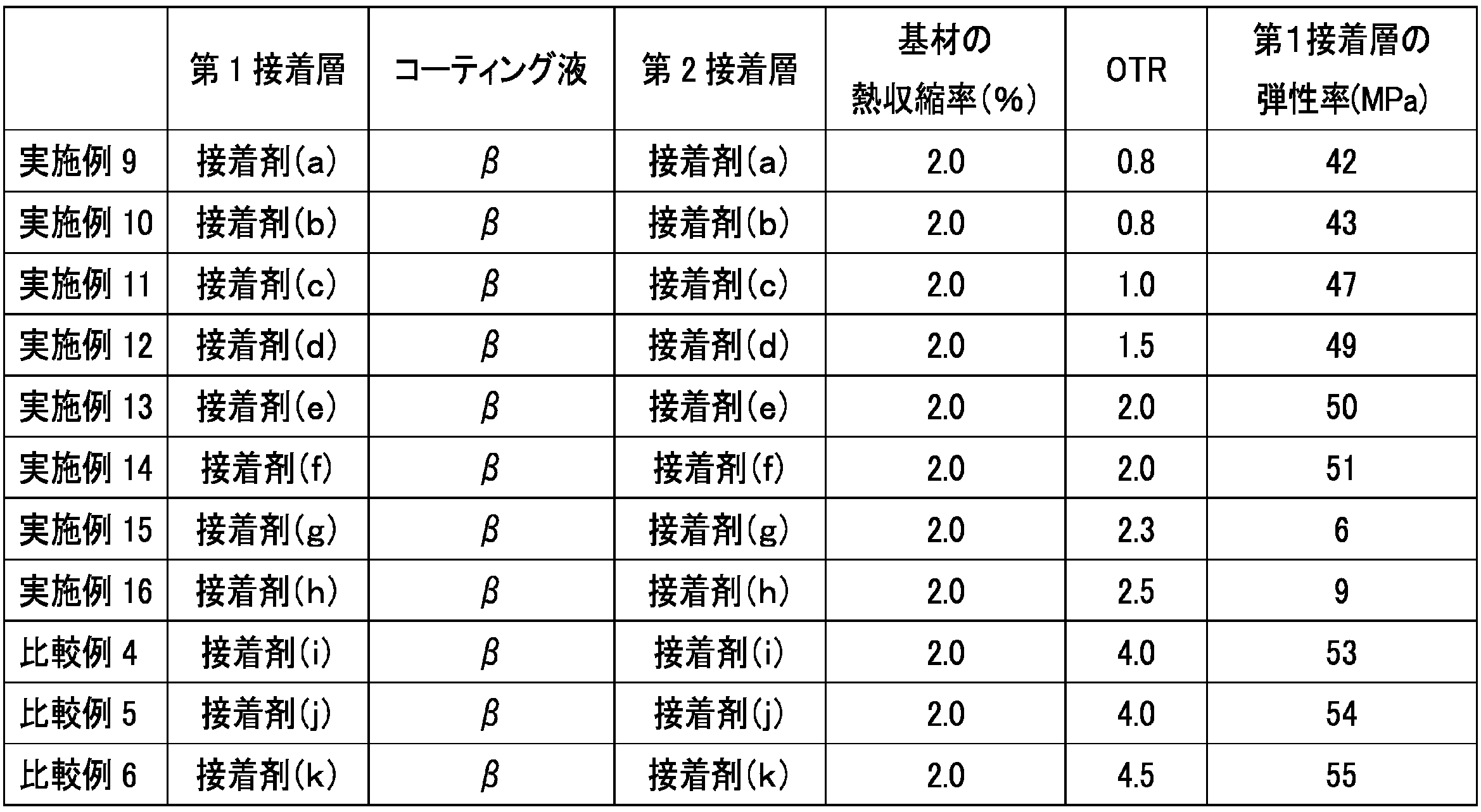
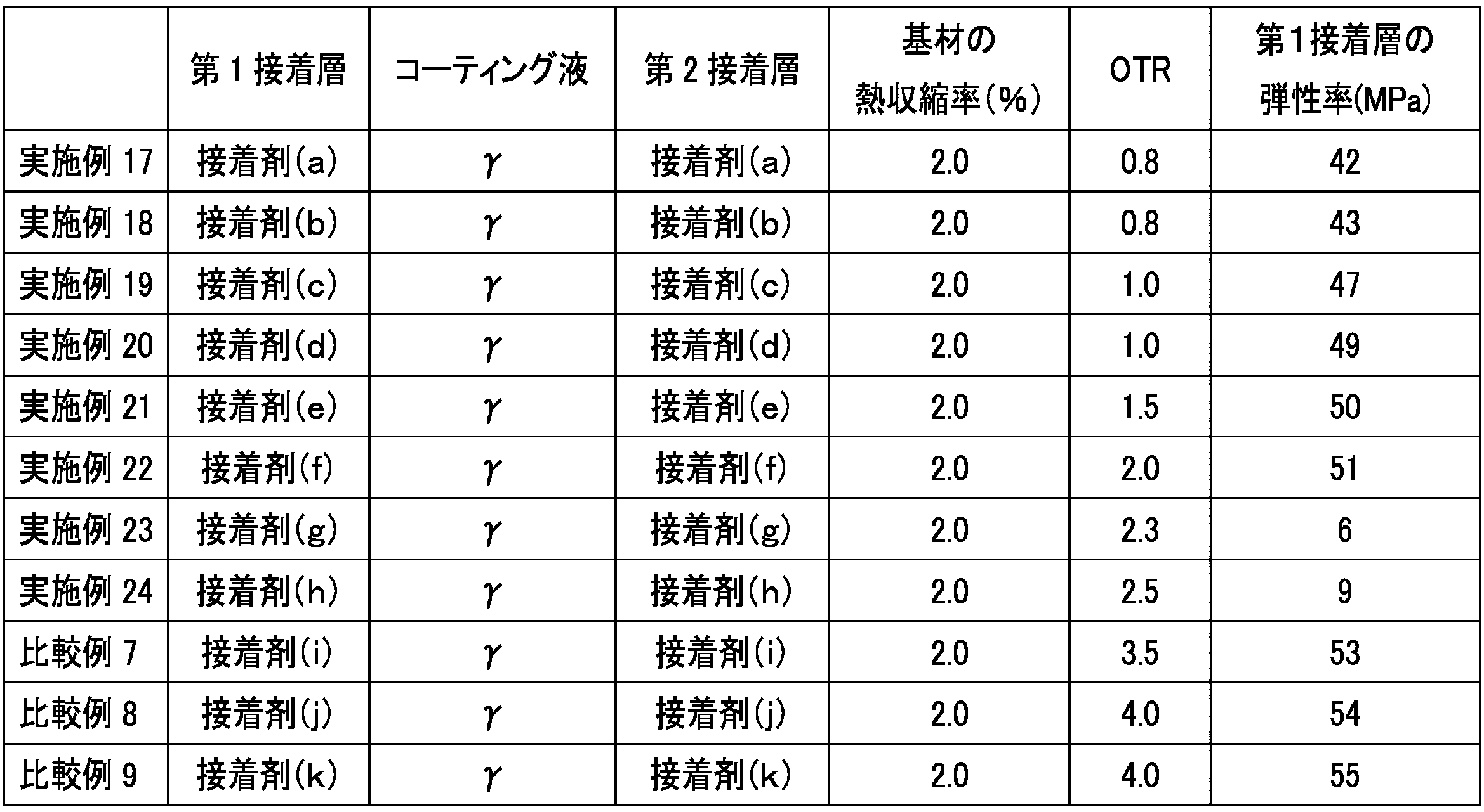
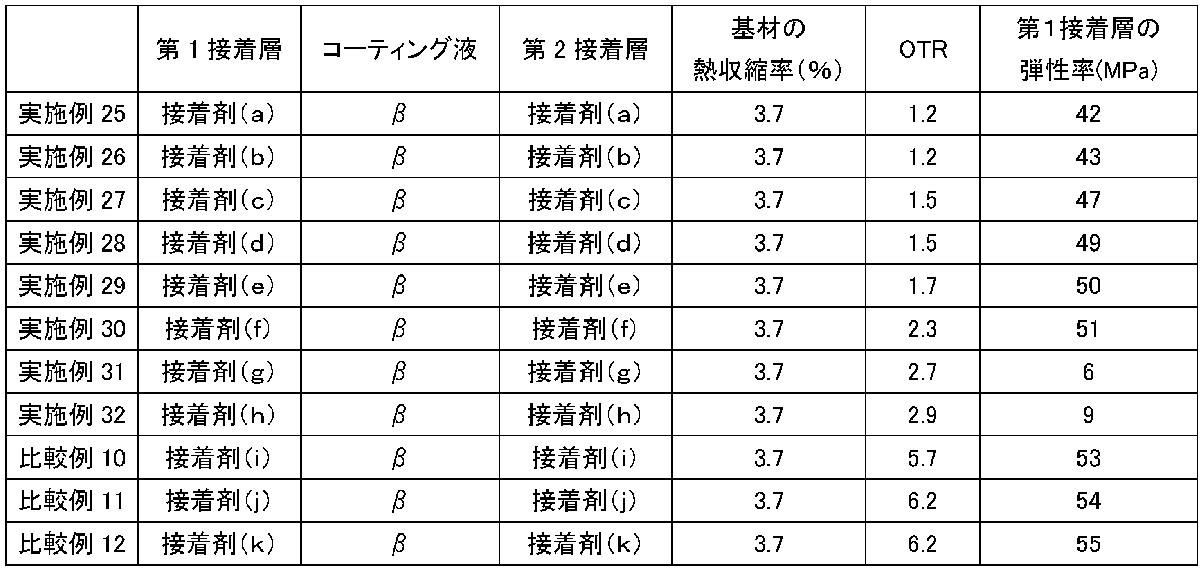

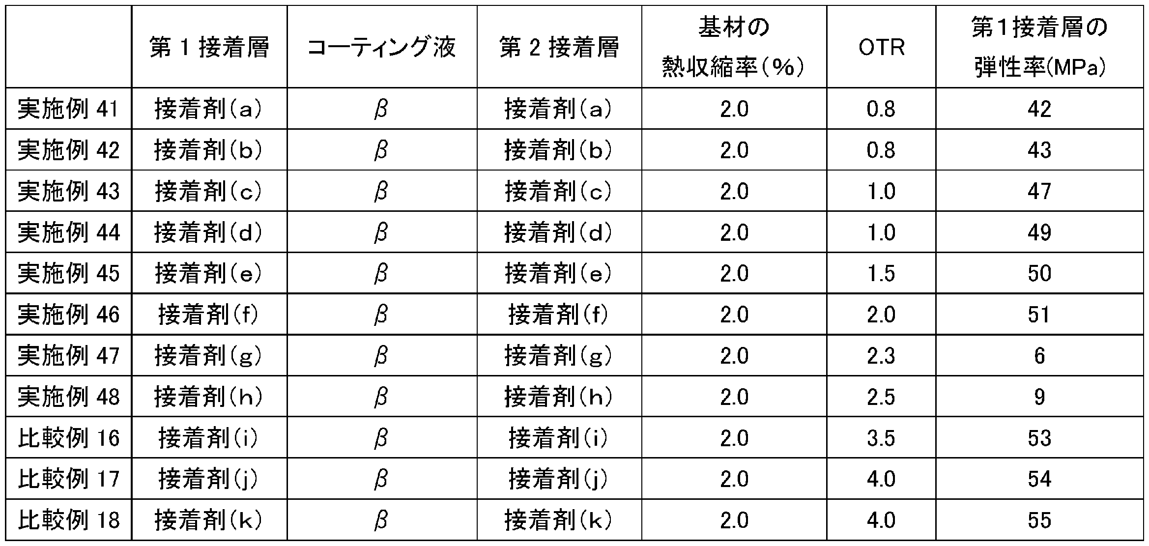
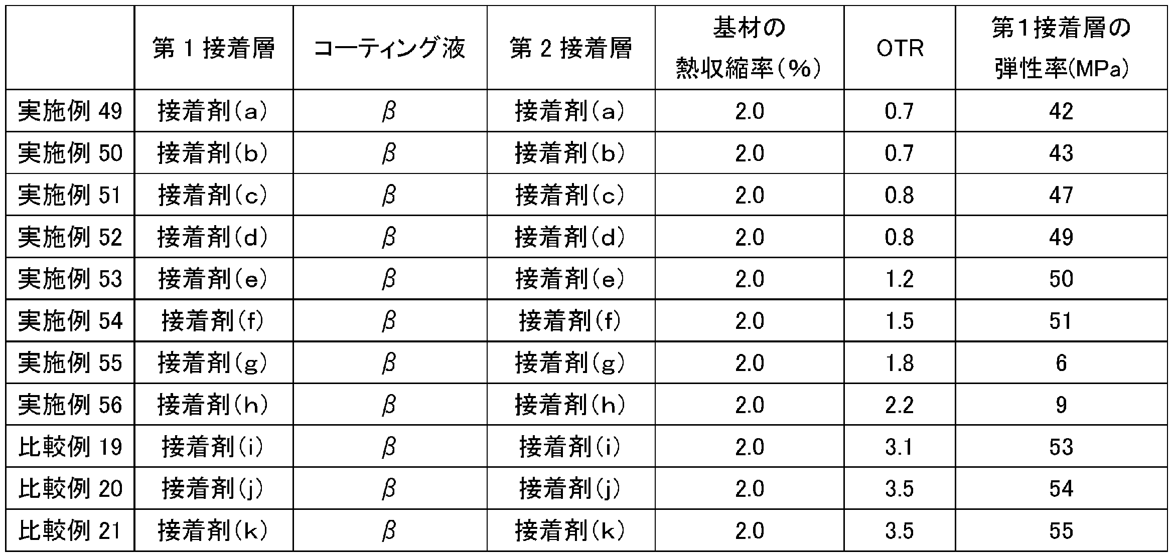


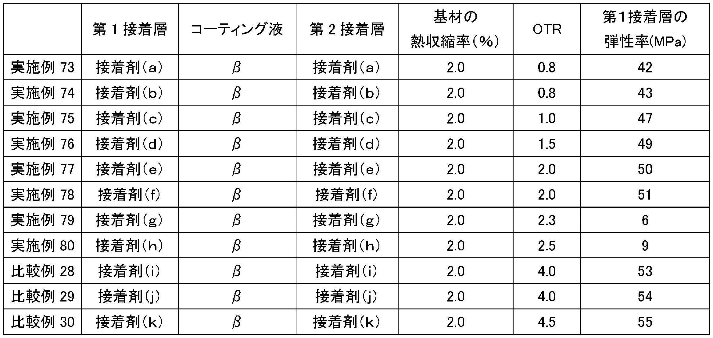
表1~3に示されるように、コーティング液αを用いた実施例及び比較例よりも、コーティング液βもしくはコーティング液γを用いた実施例及び比較例の酸素透過度が低くなっている。 As shown in Tables 1 to 3, the oxygen permeability is lower in the examples and comparative examples using coating liquid β or coating liquid γ than in the examples and comparative examples using coating liquid α.
表1~3に示されるように、基材がOPPフィルムである場合第1接着層の弾性率が43MPaを超えて大きくなるほど、積層体の酸素透過度の測定結果が高くなっている。特に表1~3に示されるように、第1接着層の弾性率が53MPa以上である場合の酸素透過度は、第1接着層の弾性率が53MPa未満である場合の酸素透過度よりも急激に大きくなる傾向がある。例えば、実施例6と比較例1とを比較した場合、比較例1の酸素透過度は、実施例6の酸素透過度の1.6倍以上である。また、実施例22と比較例7とを比較した場合、比較例7の酸素透過度は、実施例22の酸素透過度の1.5倍以上である。また、第1接着層の弾性率が10MPa未満である場合も、酸素透過度が比較的高くなっている。これは、第1接着層が柔らかすぎることによる弊害が出てきているものと推察される。以上の結果より、第1接着層の弾性率を適度な範囲に調整することによって、コーティング液の種類にかかわらず、良好な酸素透過度を示す積層体が得られると推察できる。 As shown in Tables 1 to 3, when the substrate is an OPP film, the oxygen permeability of the laminate increases as the elastic modulus of the first adhesive layer increases beyond 43 MPa. In particular, as shown in Tables 1 to 3, the oxygen permeability of the laminate when the elastic modulus of the first adhesive layer is 53 MPa or more tends to increase more rapidly than the oxygen permeability of the laminate when the elastic modulus of the first adhesive layer is less than 53 MPa. For example, when Example 6 is compared with Comparative Example 1, the oxygen permeability of Comparative Example 1 is 1.6 times or more that of Example 6. Also, when Example 22 is compared with Comparative Example 7, the oxygen permeability of Comparative Example 7 is 1.5 times or more that of Example 22. Also, when the elastic modulus of the first adhesive layer is less than 10 MPa, the oxygen permeability is relatively high. This is presumably due to the first adhesive layer being too soft. From the above results, it can be presumed that a laminate showing good oxygen permeability can be obtained regardless of the type of coating liquid by adjusting the elastic modulus of the first adhesive layer to an appropriate range.
<シーラント層の弾性率>
第1シーラント層ないし第5シーラント層のそれぞれから、20mm角のサンプルを形成した。続いて、卓上形精密万能試験機(株式会社島津製作所製 AUTOGRAPH AGS-X 5kN)を用いて、温度:30℃、湿度:70%、標点間距離:250mm、引張速度:5m/分の条件にて、各サンプルを0.05%~0.25%伸ばしたときに測定される引張応力から、第1シーラント層ないし第5シーラント層の弾性率(MD方向の弾性率、ならびに、TD方向の弾性率)を測定した。第1シーラント層ないし第5シーラント層のそれぞれにおけるMD方向の弾性率とTD方向の弾性率との測定結果は、以下の表11に示す。
<Elastic modulus of sealant layer>
A 20 mm square sample was formed from each of the first to fifth sealant layers. Next, using a bench-top precision universal testing machine (AUTOGRAPH AGS-X 5kN, manufactured by Shimadzu Corporation), the elastic modulus (elastic modulus in the MD direction and elastic modulus in the TD direction) of the first to fifth sealant layers was measured from the tensile stress measured when each sample was stretched by 0.05% to 0.25% under the conditions of temperature: 30°C, humidity: 70%, gauge length: 250 mm, and tensile speed: 5 m/min. The measurement results of the elastic modulus in the MD direction and the elastic modulus in the TD direction of each of the first to fifth sealant layers are shown in Table 11 below.
<充填適性>
各実施例及び各比較例で作製した積層体を用いて、95mm×140mmサイズの短辺の一辺を残して三方袋を作製した。続いて、給袋包装機にて水を70g充填した後に当該三方袋の開口部を加熱封止し、包装袋1000袋を作製した。そして、包装袋が良品かどうかをシール部からの水の漏れの有無によって確認した。各実施例及び各比較例における充填適性の評価は、以下の評価基準に基づいて実施した。各実施例における評価結果を以下の表12に示し、各比較例における評価結果を以下の表13に示す。
〔評価基準〕
A:良品率が98%以上
B:良品率が95%以上98%未満
C:良品率が95%未満
<Filling suitability>
Using the laminates produced in each Example and Comparative Example, a three-sided bag was produced, leaving one short side of 95 mm x 140 mm. Next, 70 g of water was filled in a bag feeder and packaging machine, and the opening of the three-sided bag was heat sealed to produce 1,000 packaging bags. The quality of the packaging bags was then confirmed based on the presence or absence of water leakage from the sealed portion. The filling suitability of each Example and Comparative Example was evaluated based on the following evaluation criteria. The evaluation results for each Example are shown in Table 12 below, and the evaluation results for each Comparative Example are shown in Table 13 below.
[Evaluation Criteria]
A: The rate of non-defective products is 98% or more. B: The rate of non-defective products is 95% or more and less than 98%. C: The rate of non-defective products is less than 95%.
<包装袋の耐久性評価>
各実施例及び各比較例で作製した積層体を用いて、95mm×140mmサイズの三方袋を作製した。この三方袋に水70gを充填した後、当該三方袋を加熱封止した。その後、128℃、15分のレトルト殺菌処理を実施し、試験用サンプルを作製した。各実施例及び各比較例にて、100袋の試験サンプルを作製した。続いて、各実施例及び各比較例にて、上記100袋の試験サンプルを、床面からの高さが100cmとなる位置から試験サンプルを床面に対して水平にして自由落下させた。当該自由落下を100回繰り返して実施した。その後、破裂しなかった試験サンプルの残存率に基づいて、包装袋の耐久性を評価した。各実施例及び各比較例における包装袋の耐久性の評価は、以下の評価基準に基づいて実施した。各実施例における評価結果を以下の表12に示し、各比較例における評価結果を以下の表13に示す。
〔評価基準〕
A:残存率が100%
B:残存率が95%以上100%未満
<Durability evaluation of packaging bags>
A three-sided bag of 95 mm x 140 mm size was produced using the laminate produced in each Example and Comparative Example. After filling this three-sided bag with 70 g of water, the three-sided bag was heat-sealed. Then, a retort sterilization treatment was performed at 128 ° C for 15 minutes to produce a test sample. In each Example and Comparative Example, 100 test samples were produced. Next, in each Example and Comparative Example, the 100 test samples were allowed to freely fall horizontally to the floor from a
[Evaluation Criteria]
A: 100% survival rate
B: Residual rate is 95% or more but less than 100%
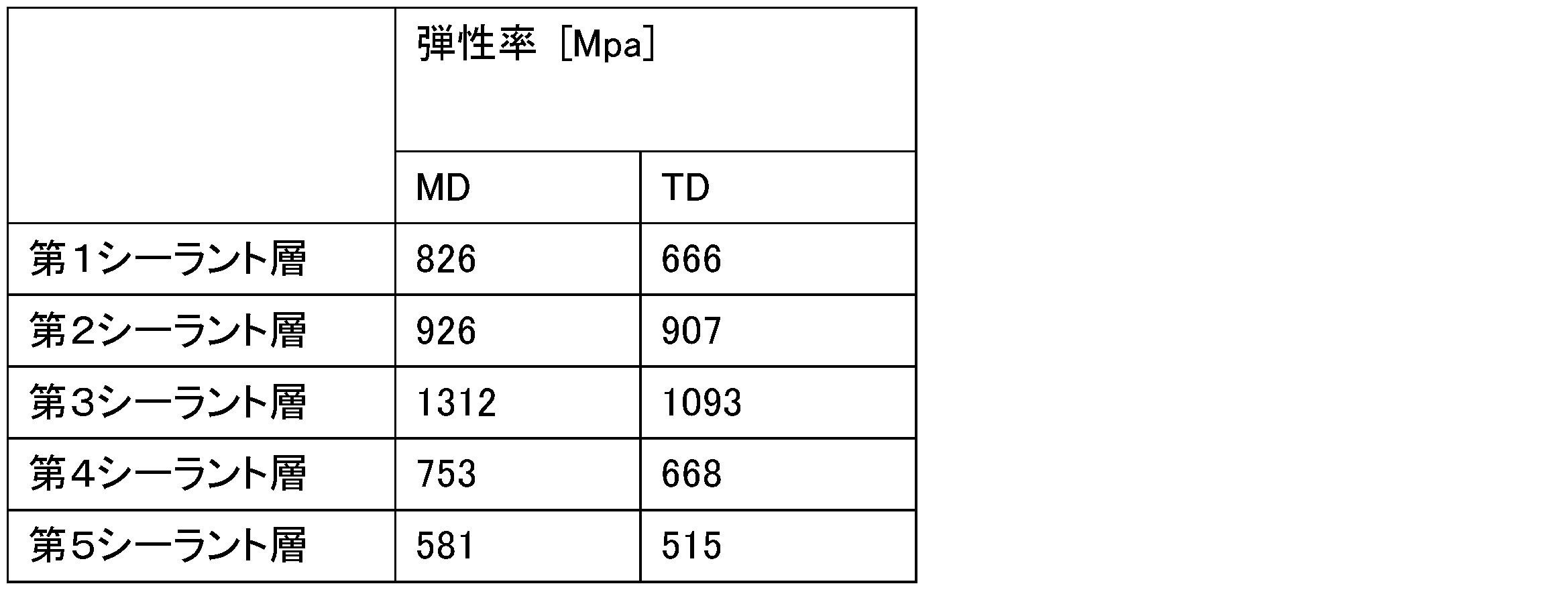


上記表12及び表13より、実施例57~72及び比較例22~27においては、実施例1~56,73~80などと比較して、包装袋の充填適性が低かった。特に、第5シーラント層が用いられている実施例65~72及び比較例25~27における包装袋の充填適性が低かった。これらは、第4シーラント層のMD方向の弾性率が第1シーラント層と比較して低かったこと、ならびに、第5シーラント層が柔らかすぎたことが一因と推察される。第3シーラント層が用いられている実施例49~56及び比較例22~24においては、実施例1~48,57~80などと比較して、包装袋の耐久性が低かった。これは、第3シーラント層が硬すぎたことが一因と推察される。 From Tables 12 and 13 above, the packaging bags in Examples 57-72 and Comparative Examples 22-27 had poorer filling suitability than those in Examples 1-56 and 73-80. In particular, the packaging bags in Examples 65-72 and Comparative Examples 25-27, in which the fifth sealant layer was used, had poor filling suitability. This is believed to be due in part to the fact that the fourth sealant layer had a lower MD modulus than the first sealant layer, and that the fifth sealant layer was too soft. The packaging bags in Examples 49-56 and Comparative Examples 22-24, in which the third sealant layer was used, had poorer durability than those in Examples 1-48 and 57-80. This is believed to be due in part to the fact that the third sealant layer was too hard.
1…積層体、10…バリア層、11…基材、12…密着層、13…蒸着層、14…バリアコート、20…シーラント層、30…第1接着層、40…支持層、50…第2接着層。 1...Laminate, 10...Barrier layer, 11...Substrate, 12...Adhesion layer, 13...Vapor deposition layer, 14...Barrier coat, 20...Sealant layer, 30...First adhesive layer, 40...Support layer, 50...Second adhesive layer.
Claims (10)
前記バリア層の第1主面に重なるシーラント層と、
前記バリア層の第2主面に重なる支持層と、
前記バリア層及び前記シーラント層を接着する第1接着層と、
前記バリア層及び前記支持層を接着する第2接着層と、
を備えるガスバリア積層体であって、
前記第1接着層は、2液硬化型のウレタン接着剤を含み、
前記基材はポリオレフィンを含み、
前記ガスバリア積層体に対してレトルト処理を実施した後、走査プローブ顕微鏡で測定された前記第1接着層の弾性率は、5MPa以上53MPa未満である、
ガスバリア積層体。 a barrier layer having a substrate on which the barrier coat is provided;
a sealant layer overlying the first major surface of the barrier layer; and
a support layer overlying the second major surface of the barrier layer; and
a first adhesive layer that adheres the barrier layer and the sealant layer;
a second adhesive layer that adheres the barrier layer and the support layer;
A gas barrier laminate comprising:
The first adhesive layer includes a two-component curing urethane adhesive,
The substrate comprises a polyolefin;
After performing a retort treatment on the gas barrier laminate, the elastic modulus of the first adhesive layer measured by a scanning probe microscope is 5 MPa or more and less than 53 MPa.
Gas barrier laminate.
前記レトルト処理の実施後、走査プローブ顕微鏡で測定された前記第2接着層の弾性率は、5MPa以上53MPa未満である、請求項1に記載のガスバリア積層体。 The second adhesive layer includes a two-component curing urethane adhesive,
The gas barrier laminate according to claim 1 , wherein the elastic modulus of the second adhesive layer measured by a scanning probe microscope after the retort treatment is 5 MPa or more and less than 53 MPa.
前記アンカーコート層は、前記基材と前記蒸着層との間に位置する、請求項1または2に記載のガスバリア積層体。 The barrier layer further comprises an anchor coat layer and a deposition layer located between the substrate and the barrier coat;
The gas barrier laminate according to claim 1 or 2, wherein the anchor coat layer is located between the substrate and the deposition layer.
前記ガスバリア積層体におけるポリオレフィンの合計質量の割合は、90質量%以上である、請求項1または2に記載のガスバリア積層体。 Each of the substrate and the sealant layer is a polyolefin film;
3. The gas barrier laminate according to claim 1, wherein a total mass ratio of the polyolefins in the gas barrier laminate is 90 mass% or more.
前記シーラント層は、無延伸ポリプロピレンフィルムである、請求項8に記載のガスバリア積層体。 The substrate is a stretched polypropylene film,
The gas barrier laminate according to claim 8 , wherein the sealant layer is a non-oriented polypropylene film.
Priority Applications (4)
| Application Number | Priority Date | Filing Date | Title |
|---|---|---|---|
| EP24823464.3A EP4725695A1 (en) | 2023-06-16 | 2024-06-14 | Gas barrier laminate and packaging |
| CN202480038645.6A CN121335806A (en) | 2023-06-16 | 2024-06-14 | Gas barrier laminates and packaging bags |
| JP2024561590A JP7632775B1 (en) | 2023-06-16 | 2024-06-14 | Gas barrier laminate and packaging bag |
| JP2025013233A JP2025065192A (en) | 2023-06-16 | 2025-01-29 | Gas barrier laminate and packaging bag |
Applications Claiming Priority (2)
| Application Number | Priority Date | Filing Date | Title |
|---|---|---|---|
| JP2023-099482 | 2023-06-16 | ||
| JP2023099482 | 2023-06-16 |
Publications (1)
| Publication Number | Publication Date |
|---|---|
| WO2024257851A1 true WO2024257851A1 (en) | 2024-12-19 |
Family
ID=93852237
Family Applications (1)
| Application Number | Title | Priority Date | Filing Date |
|---|---|---|---|
| PCT/JP2024/021651 Ceased WO2024257851A1 (en) | 2023-06-16 | 2024-06-14 | Gas barrier laminate and packaging |
Country Status (4)
| Country | Link |
|---|---|
| EP (1) | EP4725695A1 (en) |
| JP (2) | JP7632775B1 (en) |
| CN (1) | CN121335806A (en) |
| WO (1) | WO2024257851A1 (en) |
Citations (7)
| Publication number | Priority date | Publication date | Assignee | Title |
|---|---|---|---|---|
| JPH1029264A (en) * | 1996-04-16 | 1998-02-03 | Toyobo Co Ltd | Gas barrier resin film |
| JP2003236972A (en) * | 2002-02-19 | 2003-08-26 | Dainippon Printing Co Ltd | Laminated body for easy opening and retort pouch packaging material |
| JP4200972B2 (en) | 2002-11-22 | 2008-12-24 | 凸版印刷株式会社 | Gas barrier laminated film |
| JP2019217764A (en) * | 2018-06-18 | 2019-12-26 | 大日本印刷株式会社 | Low-solvent odor easily-openable gas barrier laminate using solventless adhesive, and low-solvent odor gas barrier packaging material and packaging bag comprising the laminate |
| JP2021020391A (en) * | 2019-07-29 | 2021-02-18 | 凸版印刷株式会社 | Laminate and packaging bag |
| WO2021230319A1 (en) * | 2020-05-14 | 2021-11-18 | 凸版印刷株式会社 | Gas barrier film |
| JP2023079681A (en) * | 2021-11-29 | 2023-06-08 | 凸版印刷株式会社 | Laminates and packages for packaging materials |
-
2024
- 2024-06-14 EP EP24823464.3A patent/EP4725695A1/en active Pending
- 2024-06-14 CN CN202480038645.6A patent/CN121335806A/en active Pending
- 2024-06-14 WO PCT/JP2024/021651 patent/WO2024257851A1/en not_active Ceased
- 2024-06-14 JP JP2024561590A patent/JP7632775B1/en active Active
-
2025
- 2025-01-29 JP JP2025013233A patent/JP2025065192A/en active Pending
Patent Citations (7)
| Publication number | Priority date | Publication date | Assignee | Title |
|---|---|---|---|---|
| JPH1029264A (en) * | 1996-04-16 | 1998-02-03 | Toyobo Co Ltd | Gas barrier resin film |
| JP2003236972A (en) * | 2002-02-19 | 2003-08-26 | Dainippon Printing Co Ltd | Laminated body for easy opening and retort pouch packaging material |
| JP4200972B2 (en) | 2002-11-22 | 2008-12-24 | 凸版印刷株式会社 | Gas barrier laminated film |
| JP2019217764A (en) * | 2018-06-18 | 2019-12-26 | 大日本印刷株式会社 | Low-solvent odor easily-openable gas barrier laminate using solventless adhesive, and low-solvent odor gas barrier packaging material and packaging bag comprising the laminate |
| JP2021020391A (en) * | 2019-07-29 | 2021-02-18 | 凸版印刷株式会社 | Laminate and packaging bag |
| WO2021230319A1 (en) * | 2020-05-14 | 2021-11-18 | 凸版印刷株式会社 | Gas barrier film |
| JP2023079681A (en) * | 2021-11-29 | 2023-06-08 | 凸版印刷株式会社 | Laminates and packages for packaging materials |
Also Published As
| Publication number | Publication date |
|---|---|
| JPWO2024257851A1 (en) | 2024-12-19 |
| JP7632775B1 (en) | 2025-02-19 |
| JP2025065192A (en) | 2025-04-17 |
| EP4725695A1 (en) | 2026-04-15 |
| CN121335806A (en) | 2026-01-13 |
Similar Documents
| Publication | Publication Date | Title |
|---|---|---|
| US12502877B2 (en) | Laminate and packaging bag | |
| JP7658492B2 (en) | Packaging films and bags | |
| JP7332070B1 (en) | Gas barrier laminate and packaging bag | |
| JP2022034746A (en) | Gas barrier laminate | |
| JP7231095B2 (en) | Laminates and packaging bags | |
| JP7632775B1 (en) | Gas barrier laminate and packaging bag | |
| JP2025001761A (en) | Gas barrier laminate, packaging bag and package | |
| WO2025115849A1 (en) | Laminate for packaging, and packaging bag | |
| JP7673883B1 (en) | Laminate, packaging bag and packaging body | |
| JP7473036B2 (en) | Laminate and packaging bag | |
| EP4559677A1 (en) | Laminate for packaging, method for selecting same, method for evaluating same, packaging bag, and method for producing same | |
| WO2023181852A1 (en) | Packaging laminate and packaging bag | |
| JP2025110394A (en) | Laminate and packaging bag | |
| US20250303678A1 (en) | Laminate and packaging bag | |
| CN122003326A (en) | Packaging laminates and packaging bags | |
| WO2026042584A1 (en) | Laminate and packaging material | |
| JP2023178816A (en) | Packaging laminates and packaging bags | |
| JP2024099158A (en) | Manufacturing method of packaging bag and packaging bag |
Legal Events
| Date | Code | Title | Description |
|---|---|---|---|
| WWE | Wipo information: entry into national phase |
Ref document number: 2024561590 Country of ref document: JP |
|
| 121 | Ep: the epo has been informed by wipo that ep was designated in this application |
Ref document number: 24823464 Country of ref document: EP Kind code of ref document: A1 |
|
| WWE | Wipo information: entry into national phase |
Ref document number: CN2024800386456 Country of ref document: CN |
|
| REG | Reference to national code |
Ref country code: BR Ref legal event code: B01A Ref document number: 112025027949 Country of ref document: BR |
|
| WWE | Wipo information: entry into national phase |
Ref document number: 2024823464 Country of ref document: EP |
|
| NENP | Non-entry into the national phase |
Ref country code: DE |
|
| ENP | Entry into the national phase |
Ref document number: 2024823464 Country of ref document: EP Effective date: 20260112 |
|
| ENP | Entry into the national phase |
Ref document number: 2024823464 Country of ref document: EP Effective date: 20260112 |
|
| ENP | Entry into the national phase |
Ref document number: 2024823464 Country of ref document: EP Effective date: 20260112 |
|
| WWP | Wipo information: published in national office |
Ref document number: 2024823464 Country of ref document: EP |