WO2024257873A1 - 有機物質製造装置、及び有機物質製造方法 - Google Patents
有機物質製造装置、及び有機物質製造方法 Download PDFInfo
- Publication number
- WO2024257873A1 WO2024257873A1 PCT/JP2024/021759 JP2024021759W WO2024257873A1 WO 2024257873 A1 WO2024257873 A1 WO 2024257873A1 JP 2024021759 W JP2024021759 W JP 2024021759W WO 2024257873 A1 WO2024257873 A1 WO 2024257873A1
- Authority
- WO
- WIPO (PCT)
- Prior art keywords
- temperature
- gas
- organic substance
- section
- raw material
- Prior art date
- Legal status (The legal status is an assumption and is not a legal conclusion. Google has not performed a legal analysis and makes no representation as to the accuracy of the status listed.)
- Ceased
Links
Images
Classifications
-
- C—CHEMISTRY; METALLURGY
- C10—PETROLEUM, GAS OR COKE INDUSTRIES; TECHNICAL GASES CONTAINING CARBON MONOXIDE; FUELS; LUBRICANTS; PEAT
- C10K—PURIFYING OR MODIFYING THE CHEMICAL COMPOSITION OF COMBUSTIBLE GASES CONTAINING CARBON MONOXIDE
- C10K1/00—Purifying combustible gases containing carbon monoxide
- C10K1/02—Dust removal
-
- C—CHEMISTRY; METALLURGY
- C10—PETROLEUM, GAS OR COKE INDUSTRIES; TECHNICAL GASES CONTAINING CARBON MONOXIDE; FUELS; LUBRICANTS; PEAT
- C10K—PURIFYING OR MODIFYING THE CHEMICAL COMPOSITION OF COMBUSTIBLE GASES CONTAINING CARBON MONOXIDE
- C10K1/00—Purifying combustible gases containing carbon monoxide
- C10K1/04—Purifying combustible gases containing carbon monoxide by cooling to condense non-gaseous materials
-
- C—CHEMISTRY; METALLURGY
- C12—BIOCHEMISTRY; BEER; SPIRITS; WINE; VINEGAR; MICROBIOLOGY; ENZYMOLOGY; MUTATION OR GENETIC ENGINEERING
- C12M—APPARATUS FOR ENZYMOLOGY OR MICROBIOLOGY; APPARATUS FOR CULTURING MICROORGANISMS FOR PRODUCING BIOMASS, FOR GROWING CELLS OR FOR OBTAINING FERMENTATION OR METABOLIC PRODUCTS, i.e. BIOREACTORS OR FERMENTERS
- C12M1/00—Apparatus for enzymology or microbiology
-
- C—CHEMISTRY; METALLURGY
- C12—BIOCHEMISTRY; BEER; SPIRITS; WINE; VINEGAR; MICROBIOLOGY; ENZYMOLOGY; MUTATION OR GENETIC ENGINEERING
- C12P—FERMENTATION OR ENZYME-USING PROCESSES TO SYNTHESISE A DESIRED CHEMICAL COMPOUND OR COMPOSITION OR TO SEPARATE OPTICAL ISOMERS FROM A RACEMIC MIXTURE
- C12P7/00—Preparation of oxygen-containing organic compounds
- C12P7/02—Preparation of oxygen-containing organic compounds containing a hydroxy group
- C12P7/04—Preparation of oxygen-containing organic compounds containing a hydroxy group acyclic
- C12P7/06—Ethanol, i.e. non-beverage
- C12P7/08—Ethanol, i.e. non-beverage produced as by-product or from waste or cellulosic material substrate
Definitions
- the present invention relates to an organic substance production apparatus and method for producing organic substances from a raw material gas containing carbon monoxide, carbon dioxide, and hydrogen.
- Patent Document 1 considers converting the synthesis gas obtained from waste into organic compounds such as ethanol using gas-utilizing bacteria.
- Patent Document 1 describes how the synthetic gas produced in a gasifier and reformed in a reformer is cooled to 200°C or less in a heat exchanger such as a boiler and a gas cooling tower, and then passed through a filter-type dust collector, scrubber, etc. to remove impurities before being brought into contact with gas-utilizing microorganisms.
- the synthetic gas obtained from waste contains large amounts of soot, tar, and other impurities, so if a gas cooling tower is used to cool the high-temperature synthetic gas to a low temperature, a large amount of soot and tar will be mixed into the cooling water of the gas cooling tower. This makes it easier for blockages to occur in the piping of the water circulation system and drainage system, necessitating frequent maintenance of the equipment. In addition, because large amounts of soot and tar will be mixed into the cooling water, a large-scale drainage treatment facility will be required.
- the present invention aims to provide an organic substance production apparatus and method that can efficiently produce organic substances from raw material gas containing carbon monoxide, hydrogen, and carbon dioxide by efficiently removing impurities while regulating the temperature, without requiring frequent equipment maintenance or large-scale wastewater treatment facilities.
- the present invention provides the following [1] to [10].
- a gas generating unit for generating a raw material gas containing carbon monoxide, carbon dioxide and hydrogen; an organic substance generating section to which the raw material gas is supplied and which generates an organic substance from the raw material gas; a first temperature adjusting unit that adjusts the temperature of the raw material gas discharged from the gas generating unit to a temperature within a range of 350° C. or more and 550° C. or less; A dust removal unit including a dust collector; A second temperature adjusting unit is provided to adjust the temperature of the raw material gas to 200° C. or less, The organic substance producing apparatus, wherein the first temperature adjustment section, the dust removal section, and the second temperature adjustment section are arranged in this order from upstream between the gas production section and the organic substance production section.
- [9] generating a raw material gas containing carbon monoxide, carbon dioxide and hydrogen;
- the generated raw material gas is treated in the following order at least: a step of adjusting the temperature of the raw material gas to within a range of 350° C. or more and 550° C. or less; a step of passing the raw material gas through a dust removing section; and a step of adjusting the temperature of the raw material gas to 200° C. or less;
- a method for producing an organic substance which comprises producing an organic substance from the treated raw material gas.
- the present invention provides an organic substance production apparatus and an organic substance production method that can efficiently produce organic substances from raw material gas without requiring frequent equipment maintenance or large-scale wastewater treatment facilities.
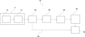
- FIG. 1 is a block diagram showing an organic substance producing apparatus according to a first embodiment
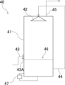
- FIG. 4 is a schematic diagram showing an example of a scrubber used in the second temperature reducing section (second temperature adjusting section).
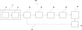
- FIG. 11 is a block diagram showing an organic substance producing apparatus according to a second embodiment.
- an organic substance producing apparatus 10 includes a gas generating section 11 that generates a raw material gas containing carbon monoxide, carbon dioxide, and hydrogen, and an organic substance producing section 50 that is supplied with the raw material gas generated in the gas generating section 11 and produces an organic substance from the raw material gas.
- the organic substance producing apparatus 10 also includes a first temperature adjusting section 20, a dust removing section 30, and a second temperature adjusting section 40, which are arranged in this order from upstream, between the gas generating section 11 and the organic substance producing section 50.
- the raw material gas generated in the gas generating section 11 passes through the first temperature adjusting section 20, the dust removing section 30, and the second temperature adjusting section 40 in this order, and is temperature-adjusted and purified by these sections before being supplied to the organic substance producing section 50.
- upstream and downstream refer to the upstream and downstream along the supply flow of the raw material gas.
- supply flow refers to the flow of the raw material gas generated in the gas generation section until it is introduced into the organic substance generation section.
- the gas generator 11 gasifies waste to generate a raw gas.
- the waste may be industrial waste such as industrial solid waste or general waste such as municipal solid waste (MSW), and may include combustible materials such as plastic waste, food waste, discarded tires, biomass waste, food waste, building materials, wood, wood chips, fiber, and paper.
- MSW municipal solid waste
- fossil fuels LNG, LPG, etc.
- LNG fossil fuels
- the gas generation unit 11 includes a gasification furnace 12 and a reformer furnace 13.
- the gasification furnace 12 is a device that generates waste-derived pyrolysis gas by burning or pyrolyzing waste.
- the gasification furnace 12 is not particularly limited, and examples thereof include a fixed bed gasification furnace such as a shaft furnace, a kiln gasification furnace, a fluidized bed gasification furnace, and a plasma gasification furnace.
- a fixed bed gasification furnace such as a shaft furnace, a kiln gasification furnace, a fluidized bed gasification furnace, and a plasma gasification furnace.
- oxygen or air, and further steam as necessary are fed into the gasification furnace 12.
- the feeding of steam contributes to improving tar reforming or gasification efficiency.
- the gasification furnace 12 pyrolyzes and gasifies the waste in an atmosphere of, for example, 500°C or higher.
- the pyrolysis gas includes not only carbon monoxide, hydrogen, and carbon dioxide, but also tar, soot, char, and the like.
- the pyrolysis gas is supplied to the reforming furnace 13. Note that solids generated as non-combustible materials in the gasification furnace 12 are appropriately recovered.
- the pyrolysis gas obtained in the gasification furnace 12 is reformed, and the content of at least one of hydrogen and carbon monoxide in the pyrolysis gas is increased, and the pyrolysis gas is discharged as a raw material gas.
- tar and char contained in the pyrolysis gas are reformed into hydrogen and carbon monoxide.
- the temperature near the gas outlet in the reformer 13 is not particularly limited, but is, for example, 900°C or higher, preferably 1,000°C to 1,400°C, and more preferably 1,100°C to 1,300°C.
- dioxin precursors for example, chlorides having a benzene ring, etc.
- dioxin resynthesis downstream is suppressed.
- the temperature by setting the temperature to be equal to or higher than the above lower limit, a sufficient reforming effect can be obtained, while by setting the temperature to be equal to or lower than the above upper limit, mechanical durability can be maintained.
- the temperature of the raw gas discharged from the reformer 13 (i.e., the gas generation section 11) and supplied to the temperature adjustment section (temperature reduction section) 20 described below is roughly the same as the temperature near the gas outlet in the reformer 13, and is, for example, 900°C or higher, preferably 1,000°C or higher and 1,400°C or lower, and more preferably 1,100°C or higher and 1,300°C or lower.
- the raw material gas discharged from the reformer 13 is a so-called synthesis gas, and contains carbon monoxide, hydrogen, and carbon dioxide as described above.
- the raw material gas discharged from the reformer 13 may contain, for example, 5 vol% or more of carbon monoxide, 5 vol% or more of hydrogen, and 5 vol% or more of carbon dioxide.
- the carbon monoxide concentration discharged from the reformer 13 is preferably 10% by volume or more and 75% by volume or less, more preferably 20% by volume or more and 70% by volume or less.
- the hydrogen concentration is preferably 10% by volume or more and 60% by volume or less, more preferably 20% by volume or more and 50% by volume or less.
- the carbon dioxide concentration is preferably 30% by volume or less.
- the raw material gas discharged from the reformer 13 may contain nitrogen, oxygen, etc. in addition to hydrogen, carbon monoxide, and carbon dioxide.
- the nitrogen concentration in the raw material gas is usually 40 vol. % or less, and preferably 20 vol. % or less.
- the oxygen concentration in the raw gas is usually less than 5% by volume, taking into consideration the explosion limit of hydrogen in the gas. The lower the oxygen concentration, the better. However, oxygen is often inevitably contained in the raw gas, and the oxygen concentration is substantially 0.01% by volume or more.
- the concentrations of carbon monoxide, carbon dioxide, hydrogen, nitrogen, and oxygen in the raw gas can be set within a predetermined range by appropriately changing the type of waste, the temperatures of the gasifier 12 and the reformer 13, the amount of oxygen or steam as a gasifying agent supplied to the gasifier 12, the concentration conditions, or by additionally feeding fossil fuels (LNG, LPG, etc.).
- LNG fossil fuels
- a large amount of oxygen or the like is supplied to increase the combustion reaction (oxidation reaction) with the raw material in order to raise the gasification temperature.
- the volume percentage of each substance in the raw material gas mentioned above refers to the volume percentage of each substance in the raw material gas discharged from the gas generation section 11, i.e., the reformer furnace 13.
- the raw material gas discharged from the reformer 13 contains soot, char, tar, etc.
- the tar contained in the raw material gas reformed in the reformer 13 is so-called polycyclic aromatic hydrocarbons, etc.
- polycyclic aromatic hydrocarbons include naphthalene (boiling point 218° C.), acenaphthylene (boiling point 280° C.), acenaphthene (boiling point 279° C.), fluorene (boiling point 295° C.), anthracene (boiling point 342° C.), phenanthrene (boiling point 340° C.), fluoranthene (boiling point 375° C.), pyrene (boiling point 404° C.), etc.
- the tar contained in the raw material gas passes through the first temperature adjustment section (first temperature reduction section) 20 and the dust removal section 30 in a generally gaseous state, but is condensed in the second temperature adjustment section (second temperature reduction section) 40, which has a temperature lower than the boiling point temperature described above, and is removed in the second temperature adjustment section (second temperature reduction section) 40.
- “removal” means reducing the concentration of the target substance in the gas by removing at least a portion of the target substance from the gas, and is not limited to completely removing the target substance.
- the gas generation unit 11 is described as having a gasification furnace 12 and a reformer furnace 13, but the gas generation unit 11 is not limited to these as long as it has at least a gasification furnace and is capable of generating raw material gas containing carbon monoxide, carbon dioxide and hydrogen.
- the gas generating unit 11 does not necessarily have to have a gasifier and a reformer separately, and may be an apparatus in which the gasifier 12 and the reformer 13 are integrated. In other words, if it includes a region in which gasification is performed and a region in which the generated gas generated in the region is reformed, it is considered to be equipped with the gasifier 12 and the reformer 13.
- the gas generating unit 11 may be an apparatus in which the gasifier 12 and the reformer 13 are integrated.
- the raw material gas generated in the gas generation unit 11 passes through the first temperature adjustment unit 20, the dust removal unit 30, and the second temperature adjustment unit 40 in this order.
- the first temperature adjustment unit 20 may adjust the temperature of the raw material gas discharged from the gas generation unit 11 to within a range of 350°C to 550°C, but is preferably a temperature reduction unit that reduces the temperature of the raw material gas discharged from the gas generation unit 11 to within a range of 350°C to 550°C.
- the fact that the first temperature adjustment unit is a temperature reduction unit is preferable because it indicates that the temperature of the gas generated in the gas generation unit is high and in a reformed state.
- the first temperature adjustment unit is a temperature reduction unit
- the first temperature adjustment unit may be referred to as the first temperature reduction unit.
- the raw material gas is supplied to the dust removal unit 30 in a state in which the temperature is adjusted to within a temperature range of 350°C to 550°C.
- the raw material gas reformed in the reformer 13 contains tar (particularly polycyclic aromatic hydrocarbons) as described above, and the boiling point of these tars is approximately 200 to 400°C. Therefore, by heating the raw material gas to a temperature of 350°C or higher in the first temperature reducing section (first temperature adjustment section) 20 and then passing it through the dust removal section 30, the tar contained in the raw material gas becomes approximately equal to or higher than the dew point, and the raw material gas can pass through the first temperature reducing section (first temperature adjustment section) 20 and the dust removal section 30 without being condensed in the first temperature reducing section (first temperature adjustment section) 20 and the dust removal section 30.
- tar particularly polycyclic aromatic hydrocarbons
- the high-temperature raw material gas is prevented from passing through the dust removal section 30, thereby reducing the heat resistance of the equipment that constitutes the dust removal section 30 and maintaining the robustness of the dust removal section 30.
- the temperature of the raw material gas is preferably reduced to 350° C. or more and 550° C. or less, and more preferably to 400° C. or more and 450° C. or less.
- the raw material gas is preferably supplied to the dust removing section 30 in a state where the temperature of the raw material gas is reduced to a temperature range of 350° C. or more and 550° C. or less, more preferably to a temperature range of 400° C. or more and 450° C. or less. This is because the heat resistance of the metal structure of the dust removal section becomes poor when the temperature exceeds 550°C, and because resynthesis of dioxin precursors that may be contained in the dust may be promoted when the temperature drops below 350°C.
- the first temperature reducing section 20 may be composed of a boiler.
- the raw material gas which is a gasification gas
- the first temperature reducing section 20 By passing the raw material gas, which is a gasification gas, through the inside of the boiler, heat exchange occurs with the heat transfer section of the boiler, and the water flowing inside is turned into steam or the steam is superheated, and at the same time, the raw material gas is cooled.
- a boiler is used as the first temperature reducing section 20
- heat can be recovered from the high-temperature raw material gas, and the thermal energy of the raw material gas can be effectively utilized, such as by easily heating other devices with the generated steam.
- the steam generated in the boiler is supplied to a separation device 55, which will be described later, through a thermal energy path 25 connecting the first temperature reducing section 20 and the separation device 55, and is used to purify organic substances.
- the temperature at or above the saturation temperature in the first temperature reducing section 20 it is possible to prevent impurities such as soot and tar contained in the raw material gas from migrating into the cooling water, which would cause contaminated wastewater or blockage in the circulating water system. This makes it possible to reduce the frequency of maintenance of this section. Furthermore, the load of treating wastewater containing soot and tar in the first temperature reducing section 20 can also be reduced.
- the dust removal section 30 removes solid substances contained in the raw gas through which the raw gas passes. Specifically, soot and char are mainly removed in the dust removal section 30.
- the dust removal section 30 is not particularly limited as long as it can remove soot, char, etc., and a dust collector may be used, but a device that removes solid substances in a dry state is preferable, and a filter-type dust collector such as a filter is more preferable.
- the filter is preferably a dry filter. A dry filter is preferable because it can suppress pollution of the wastewater and reduce the cost of treating the wastewater.
- the reason why the cost of treating the wastewater can be reduced is that in a wet method using water, soot and dust are mixed into the water during the dust removal process, making the wastewater treatment complicated and expensive, so by using a dry filter, the amount of soot and dust contained in the wastewater can be reduced, which contributes to reducing the cost of treating the wastewater.
- the filter includes a filter material capable of capturing solid substances such as soot and char contained in the raw gas, and a casing that houses the filter material.
- a filter material that has heat resistance specifically a ceramic filter using ceramic as the filter material, or a metal filter using metal as the filter material.
- high-temperature gas in the range of 350 to 550°C is supplied to the dust removal unit 30 and passes through it, but by using a heat-resistant filter material such as ceramic as the filter material, it is possible to continue using the filter-type dust collector for a long period of time.
- the ceramic filter is preferably one that has excellent thermal shock resistance.
- a ceramic filter that has excellent thermal shock resistance is a ceramic filter that is ceramic-coated on a cloth-like material.
- a filter that has excellent thermal shock resistance such as a ceramic-coated cloth-like material, can suppress the occurrence of cracks that may occur due to repeated deformation caused by repeated expansion and contraction due to heat, and can improve durability.
- it is preferable that only the ends of the ceramic filter are fixed. Examples of filters that have only the ends fixed include hanging filters and candle filters. By using a hanging type as described above, the ceramic filter can be designed to be difficult to come off.
- the mesh size of the ceramic filter is, for example, 1 ⁇ m to 100 ⁇ m, preferably 1 ⁇ m to 50 ⁇ m, and more preferably 1 ⁇ m to 10 ⁇ m. If the mesh size is within the above range, dust can be collected efficiently and pressure loss can be reduced. In addition, passing the soot through the filter at a temperature of 350° C. or higher is preferable because the viscosity of the organic substances contained in the soot is unlikely to increase, making it less likely to clog.
- the dust removal section 30 may be other than a filter-type dust collector, for example, a multi-cyclone.
- a multi-cyclone is a device with multiple cyclones arranged in parallel. Each cyclone generates centrifugal force by swirling the raw gas passing through it, and this centrifugal force separates and removes solid materials contained in the raw gas.
- a multi-cyclone can remove fine solid materials by reducing the diameter of each cyclone. There are no particular limitations on the diameter of each cyclone in a multi-cyclone, but it is preferable to select a cyclone diameter that sets the limit particle diameter that can capture the majority of the soot particle size.
- the dust removal section 30 may be configured by combining two or more dust removal devices, or may combine a filter dust collector such as a ceramic filter with a multi-cyclone.
- a filter dust collector such as a ceramic filter
- a multi-cyclone and a filter dust collector may be arranged from upstream.
- the raw gas passes through the filter dust collector after a certain amount of solid matter is removed by the multi-cyclone. Therefore, the raw gas has a lower solid matter content when passing through the filter dust collector, which reduces the frequency of backwashing in the filter material of the filter dust collector and reduces fluctuations in the amount of raw gas caused by the introduction of backwash gas.
- two or more filter dust collectors and multi-cyclones may be used, and multiple filter dust collectors or multiple multi-cyclones may be arranged in series or parallel to the supply flow.
- the dust concentration in the raw gas after passing through the dust removal section 30 is sufficiently lower than the dust concentration in the raw gas before passing through the dust removal section 30, and is, for example, 10 mg/Nm3 or less. Depending on the type of the dust removal section 30, it is also possible to make the dust concentration 5 mg/Nm3 or less .
- the raw material gas also contains tar as described above, and the temperature of the raw material gas when passing through the dust removal section 30 is relatively high as described above.
- the tar contained in the raw material gas is captured by adhering to soot or a powdery adsorbent (such as slaked lime or activated carbon) in the dust removal section 30, but gaseous tar is hardly captured and passes through the dust removal section 30 almost as it is. Therefore, the concentration of tar in the raw material gas after passing through the dust removal section 30 remains almost the same as the concentration at the outlet of the reformer 13, and is then supplied to the second temperature adjustment section (second temperature reduction section) 40.
- the adsorbent is, for example, blown into the raw material gas at the inlet of the filter-type dust collector, and adheres to the filter material to capture tar and the like as the raw material gas passes through.
- the raw gas that has passed through the dust removal section 30 is supplied to the second temperature adjustment section 40, and the temperature of the raw gas that has passed through the dust removal section 30 may be adjusted to 200°C or less in the second temperature adjustment section 40.
- the second temperature adjustment section is preferably a second temperature reduction section that reduces the temperature of the raw gas that has passed through the dust removal section 30 to 200°C or less.
- the second temperature adjustment section will be described as a temperature reduction section, and the second temperature adjustment section may be referred to as a second temperature reduction section.
- the second temperature adjustment section (second temperature reduction section) 40 By adjusting the temperature to 200°C or less in the second temperature adjustment section (second temperature reduction section) 40, tar that has not been removed in the dust removal section 30 is removed in the second temperature reduction section 40 by condensation or the like.
- the temperature to 200°C or less when gas-assimilating bacteria are used in the organic matter production section 50 described later, it is easy to adjust the temperature to a suitable temperature for generating organic matter using gas-assimilating bacteria in the organic matter production section 50.
- by rapidly cooling and reducing the temperature to 200°C or less resynthesis of dioxins can also be suppressed.
- the second temperature reducing section 40 In addition, impurities such as tar are removed in the second temperature reducing section 40, but impurities that are solid even at high temperatures, such as soot and char, are mostly removed in the dust removing section 30, so the amount of impurities removed in the second temperature reducing section 40 is small. Therefore, for example, in one example of the second temperature reducing section 40, the amount of impurities mixed into the cleaning liquid of the gas cleaning temperature reducing tower described below is reduced, and the occurrence of problems such as blockage of the piping of the cleaning liquid circulation equipment in the gas cleaning temperature reducing tower is reduced, and the frequency of equipment maintenance of the gas cleaning temperature reducing tower can be reduced.
- the raw material gas is preferably cooled to 150°C or less in the second temperature reduction section 40, and more preferably cooled to 100°C or less, from the viewpoint of facilitating the removal of tar in the second temperature reduction section 40 and facilitating the production of organic substances by gas-utilizing bacteria in the organic substance production section 50.
- gas-utilizing bacteria it is preferable to further reduce the temperature to 50°C or less.
- the raw material gas is preferably cooled to a temperature of 10°C or more, more preferably cooled to a temperature of 20°C or more, and more preferably cooled to a temperature of 30°C or more.
- the tar concentration is no longer at the dew point at the outlet temperature of the second temperature reduction section 40, and the lower the temperature after temperature reduction, the lower the remaining tar concentration. Normally, if the temperature after temperature reduction is below 100°C, tar is not detected.
- the raw material gas is supplied to the second temperature reducing section 40 with almost no temperature reduction after being temperature-adjusted (preferably reduced) in the first temperature adjustment section (first temperature reducing section) 20. Therefore, the temperature of the raw material gas supplied to the second temperature reducing section 40 is, for example, 350°C or higher and 550°C or lower, but is preferably 400°C or higher and 450°C or lower.
- the second temperature reducing section 40 is preferably one in which the temperature is reduced by direct contact between the gas and a solvent such as water, and is more preferably a gas cleaning temperature reducing tower.
- the gas cleaning temperature reducing tower is a device that brings a cleaning liquid such as water or oil into contact with the raw gas, and removes various impurities while reducing the temperature of the raw gas by the cleaning liquid.
- examples of the impurities to be removed include tar.
- the cleaning liquid may be water alone or oil alone, but a chemical may also be added as appropriate.
- the second temperature reducing section 40 may also remove water-soluble gas components such as acid gases such as hydrogen sulfide, hydrogen chloride, and hydrocyanic acid, basic gases such as ammonia, and oxides such as NOx and SOx. Among these, the second temperature reducing section 40 typically removes at least hydrogen chloride and SOx.
- a scrubber is preferably used as the gas cleaning/desuperheating tower.
- a scrubber is a device that cools the raw gas while cleaning it by bringing a cleaning liquid into contact with the raw gas passing through the tower.
- the scrubber may be an oil scrubber in which the cleaning liquid is oil, but a water scrubber in which the cleaning liquid is water is preferred. By using a water scrubber, the raw gas can be easily cooled to a low temperature at low cost.
- a scrubber is used as the gas cleaning desuperheater.
- Scrubbers can be of either dry or wet type, but a wet scrubber is particularly preferred.
- a wet scrubber is preferred because it can remove water-soluble substances, making it easier to remove impurities.
- the pooled water type scrubber, Moretana type scrubber, and Neobritt type scrubber can efficiently remove impurities, a pressure loss occurs in the introduced gas. When priority is placed on impurity removal, the pooled water type scrubber, Moretana type scrubber, and Neobritt type scrubber are preferable.
- unpacked scrubbers have less pressure loss. When priority is placed on pressure loss, it is more preferable to use an unpacked scrubber. When an unpacked scrubber is used, a process of further removing impurities may be included.
- the wet scrubber is not particularly limited as long as it has a configuration for contacting the raw gas with the cleaning liquid.
- the raw gas passing through the inside of the scrubber 41 from the bottom to the top is contacted with the cleaning liquid sprayed from the top of the scrubber 41, thereby cleaning and cooling the raw gas.
- the cleaning liquid is preferably water.
- the scrubber 41 is preferably provided with an inlet passage 43, a supply passage 44, a discharge passage 45, etc.
- a storage section 46 in which the cleaning liquid is stored is provided at the bottom of the scrubber 41. The cleaning liquid stored in the storage section 46 may be appropriately stirred by a stirring device not shown.
- the inlet passage 43 is a path for introducing the raw gas into the scrubber 41, and the inlet 43A of the inlet passage 43 is provided, for example, above the liquid level of the cleaning liquid stored in the storage section 46 inside the scrubber 41.
- the supply path 44 circulates the cleaning liquid in the scrubber 41 and supplies the cleaning liquid so as to contact the raw material gas. Specifically, the supply path 44 sprays the cleaning liquid stored in the storage section 46 from the nozzle 42 downward inside the scrubber 41 and contacts the raw material gas.
- a pump (not shown) is provided in the supply path 44, and the cleaning liquid is pressure-fed to the nozzle 42 by the pump. Then, the cleaning liquid is sprayed downward from the nozzle 42 inside the scrubber 41.
- the discharge path 45 is provided in the upper part of the scrubber 41 and discharges the raw material gas after contacting the cleaning liquid sprayed from the nozzle 42 to the outside.
- the scrubber 41 may be provided with a removal device 47.
- the removal device 47 is, for example, a device for removing impurities such as tar contained in the cleaning liquid.
- a circulation path for circulating the water in the storage section 46 is provided, and the removal device 47 may be provided in the middle of the path.
- the removal device 47 may remove, for example, oily impurities such as tar contained in the cleaning liquid, solid impurities that do not dissolve in the cleaning liquid, and water-soluble impurities that dissolve in the cleaning liquid. Therefore, the removal device 47 may be an oil-water separation device or the like, a filter that removes solid matter, or a combination of two or more of these, or may have any configuration as long as it can remove impurities contained in the cleaning liquid.
- the removal device 47 is provided in the scrubber 41 to prevent impurities from accumulating in the cleaning liquid. Furthermore, the moisture in the raw gas supplied to the first temperature reducing section 20 is contained in the raw gas at a saturated state at the temperature of the raw gas, but water at the dew point falls into the cleaning liquid side due to temperature reduction in the first temperature reducing section 20. Therefore, in the scrubber 41, the increased and overflowing water is discharged to the outside of the system, but in the present invention, the treatment of this wastewater is simplified because of the small amount of soot.
- the temperature of the cleaning liquid that comes into contact with the raw gas in the scrubber 41 is less than the saturation temperature of 100°C in the case of water, and is preferably between 0°C and 40°C. In the case of water, the temperature of the cleaning liquid is kept within the above range, so that the circulating water is constantly cooled, thereby cooling the raw gas without evaporating more than necessary.
- the raw gas may be cooled to within the temperature range described above in the scrubber 41.
- By cooling the raw gas to a low temperature it is not necessary to provide a separate cooling device downstream of the scrubber 41, and even if a cooling device is provided, the load on the cooling device can be reduced, allowing raw gas at an appropriate temperature to be supplied to the organic matter generation section 50.
- the scrubber 41 is preferably provided with a temperature control device for cooling the circulating cleaning liquid (not shown), and the temperature of the cleaning liquid is preferably controlled by the temperature control device.
- the temperature control device may be attached to the supply path 44, for example, to adjust the temperature of the cleaning liquid passing through the inside of the supply path 44, or may be provided in the storage section 46 to adjust the temperature of the cleaning liquid stored in the storage section 46 of the scrubber 41.
- the temperature control device may cool the cleaning liquid passing through the supply path 44 or the cleaning liquid stored in the storage section 46 to keep the temperature within the above-mentioned range.
- the water stored in the storage section 46 may also be replaced as appropriate to maintain the temperature of the water in contact with the raw material gas within a certain temperature range.
- the scrubber 41 is described as being of a mode in which the raw gas comes into contact with the cleaning liquid sprayed from the nozzle 42, but other modes may also be used.
- the scrubber may be of a Moretana type, in which a plurality of shelves are provided in the scrubber, a layer of cleaning liquid is formed on the shelves, the raw gas is introduced into the layer from the bottom of the scrubber, and the gas rises in the layer, thereby bringing the cleaning liquid into contact with the gas.
- the temperature of the cleaning liquid in contact with the raw material gas and the temperature of the raw material gas i.e., the temperature of the raw material gas introduced into the scrubber 41 and the temperature of the raw material gas after cooling
- the temperature of the raw material gas introduced into the scrubber 41 and the temperature of the raw material gas after cooling are as described above.
- the raw material gas that has passed through the first temperature reducing section 20, the dust removing section 30, and the second temperature reducing section 40 is then supplied to the organic matter generating section 50.
- the raw material gas supplied to the organic matter generating section 50 is brought into contact with a microbial catalyst to generate organic matter.
- the microbial catalyst is a gas-utilizing bacterium.
- the microorganism may be any microorganism that generates organic matter from the raw material gas by the fermentation action of the gas-utilizing bacterium, and is preferably a microorganism having a metabolic pathway for acetyl-COA.
- the gas-utilizing bacterium may be either eubacteria or archaea, but is preferably of the genus Clostridium.
- the organic substance production section 50 includes a fermenter (reactor) filled with a culture solution containing water and gas-utilizing bacteria.
- a raw material gas is supplied to the inside of the fermenter, and the raw material gas is converted into an organic substance inside the fermenter.
- the organic substance is, for example, an alcohol, and preferably includes either ethanol or isopropanol, and more preferably includes ethanol.
- the fermenter is preferably a continuous fermentation apparatus, and may be any of agitation type, airlift type, bubble column type, loop type, open bond type, and photobio type.
- the raw material gas and culture solution may be continuously supplied to the fermenter, but it is not necessary to supply the raw material gas and culture solution simultaneously, and the raw material gas may be supplied to a fermenter to which culture solution has been previously supplied.
- the raw material gas is generally blown into the fermenter through a sparger or the like.
- the raw material gas may also be supplied intermittently to the fermenter.
- the medium used for culturing the microbial catalyst is not particularly limited as long as it has an appropriate composition according to the bacteria, but is a liquid containing water as a main component and nutrients (e.g., vitamins, phosphoric acid, etc.) dissolved or dispersed in the water.
- organic substances are produced by microbial fermentation of the gas-assimilating bacteria, and an organic substance-containing liquid is obtained.
- the temperature of the fermenter is preferably controlled to 40° C. or lower. By controlling the temperature to 40° C. or lower, the microbial catalyst in the fermenter is not killed, and organic substances such as ethanol are efficiently produced by contacting the raw material gas with the gas-utilizing bacteria.
- the temperature of the fermenter is more preferably 38° C. or lower, and in order to enhance catalytic activity, is preferably 10° C. or higher, more preferably 20° C. or higher, and even more preferably 30° C. or higher.
- the organic substance production apparatus preferably includes a separation device 55 for separating organic substances from an organic substance-containing liquid.
- the separation device 55 preferably includes a distillation device, and more preferably includes a solid-liquid separation device in addition to the distillation device.
- the separation device 55 is more preferably a combination of a solid-liquid separation device and a distillation device. The separation process performed by combining a solid-liquid separation device and a distillation device will be specifically described below.
- the organic substance-containing liquid obtained in the organic substance generation section 50 may be separated in a solid-liquid separation device into a solid component mainly consisting of microorganisms and a liquid component containing organic substances.
- the organic substance-containing liquid obtained in the organic substance generation section 50 contains the microorganisms and their corpses contained in the fermentation tank as solid components in addition to the target organic substance, so solid-liquid separation is performed to remove these.
- solid-liquid separation devices include filters, centrifuges, and devices that use a solution precipitation method.
- the solid-liquid separation device may also be a device (e.g., a heat drying device) that evaporates the liquid component containing the organic substance from the organic substance-containing liquid and separates it from the solid component. At this time, all of the liquid component containing the target organic substance may be evaporated, or the liquid component may be partially evaporated so that the target organic substance is preferentially evaporated.
- the distillation apparatus performs distillation to separate the target organic substance.
- the distillation apparatus can purify a large amount of organic substance to a high purity with a simple operation by separation by distillation.
- the distillation apparatus performs distillation to further separate the target organic substance from the liquid component separated by the solid-liquid separation apparatus, thereby purifying a large amount of organic substance to a higher purity.
- a known distillation column or the like can be used as the distillation apparatus.
- the distillation may be operated, for example, so that the distillate contains the target organic substance (e.g., ethanol) at a high purity, while the bottoms (i.e., distillation residue) contains water as a main component (e.g., 70% by mass or more, preferably 90% by mass or more).
- the target organic substance e.g., ethanol
- water e.g., 70% by mass or more, preferably 90% by mass or more.
- the temperature inside the distillation apparatus during distillation of an organic substance is not particularly limited, but is preferably 100° C. or lower, and more preferably about 70° C. or higher and 95° C. or lower.
- the pressure in the distillation apparatus during distillation of the organic substance may be normal pressure, but is preferably less than atmospheric pressure, more preferably about 60 kPa to 95 kPa (absolute pressure).
- the distillation apparatus preferably uses the thermal energy obtained from the raw material gas in the first temperature reduction section 20 for distillation.
- the distillation apparatus can increase the temperature inside the distillation apparatus during distillation of the organic substance by reusing the thermal energy obtained from the raw material gas in the first temperature reduction section 20. In this way, the distillation apparatus can reduce the energy consumption of the entire production process of the organic substance by reusing the thermal energy obtained from the raw material gas in the first temperature reduction section 20.
- the thermal energy obtained from the raw material gas in the first temperature reduction section 20 can be transferred via a thermal energy path 25 connected to the first temperature reduction section 20 and the distillation apparatus.
- the thermal energy path 25 is not particularly limited, and may have any configuration that transfers the thermal energy of the raw material gas from the first temperature reduction section 20 to the distillation apparatus by a heat medium.
- the first temperature reduction section 20 is preferably configured by a boiler, and therefore, steam is preferable as the heat medium. By using steam as the heat medium, it is easy to reuse the thermal energy of the raw material gas.
- the water separated in the separation device 55 may be reused, for example, by being supplied to the gas cleaning and cooling tower of the second cooling section 40 and used as a cleaning liquid in the gas cleaning and cooling tower. In this way, recycling of water is preferable from the viewpoints of environmental protection and economy, since the water no longer needed in the organic substance generation section 50 is not discharged as wastewater.
- the organic substance producing apparatus 10 may have a water supply path (not shown) that connects the separation device 55 and the gas cleaning and cooling tower of the second cooling section 40 and supplies the water obtained in the separation device 55 to the gas cleaning and cooling tower.
- the water supply path is not particularly limited, but may be composed of piping or the like.
- the water separated in the separation device 55 may be further refined to increase its purity and supplied to the gas cleaning and cooling tower.
- the raw gas generated in the gas generation unit 11 is temperature-adjusted to a range of 350°C to 550°C in the first temperature adjustment unit 20 before passing through the dust removal unit.
- soot and char are mostly removed in the dust removal unit 30, but at the same time, the second temperature adjustment unit 40 prevents the soot and char from being mixed into the cleaning liquid, etc.
- the second temperature adjustment unit 40 further removes tar from the raw gas. Therefore, the configuration of the first temperature adjustment unit 20, the dust removal unit 30, and the second temperature adjustment unit in their respective temperature ranges results in an efficient equipment with excellent maintainability and operability.
- an organic substance production apparatus 10A has the same configuration as the organic substance production apparatus in the first embodiment, except that a gas holder 60 is provided upstream of an organic substance generator 50.
- a gas holder 60 is provided upstream of an organic substance generator 50.
- the gas holder 60 is preferably provided upstream of the organic substance generator 50 and downstream of the second temperature adjustment unit 40, and is a device for temporarily storing the source gas supplied from the second temperature adjustment unit 40.
- the source gas is supplied to the organic substance generator 50 via the gas holder 60.
- the raw gas is temporarily stored in the gas holder 60, so that the supply amount (mass flow rate) of the raw gas per unit time to the organic substance generation unit 50 and the fluctuation of the composition can be suppressed and, for example, these can be made approximately constant. Therefore, the amount of organic matter generated per unit time can be increased without inactivating the gas-assimilating bacteria.
- the type of gas holder 60 is not particularly limited as long as it can temporarily store the gas, but it is preferable that the gas holder has a capacity that can stabilize the supply amount per unit time of the source gas or fluctuations in the composition at the outlet. This allows stable generation of organic substances in the organic substance generation section 50. If it is difficult to sufficiently level the gas composition with only space inside, it is advisable to install a stirring device.
- the internal pressure of the gas holder is not particularly limited, but if it is equal to or higher than the pressure (e.g., 500 kPa or higher) that can supply the raw material gas of the organic substance generation unit 50, there is no need to install a booster blower at the gas holder outlet.
- the internal pressure of the gas holder is the required pressure (500 to 700 kPa) at the inlet of the organic substance generation unit 50 + about 100 kPa.
- the first temperature reduction section 20 is configured by a boiler.
- the first temperature reduction section 20 may be configured by something other than a boiler as long as it can reduce the temperature of the raw material gas to 350°C or higher and 550°C or lower.
- a water spray type deheater may be used. Even when a water spray type desuperheater is used, it is preferable to reduce the temperature to the above-mentioned temperature range in the first desuperheater section 20 by the water spray type desuperheater.
- the water spray type desuperheater cools the raw material gas by spraying cooling water at the outlet of the reformer 13.
- the water spray type desuperheater may have one water spray port or multiple water spray ports.
- the water spray port may be provided on the inner circumferential surface of the desuperheater that constitutes the path through which the raw material gas passes, or may be located further inside than the inner circumferential surface, for example, at the center of the path.
- the raw gas supplied to the temperature reduction section 20 (i.e., the water spray type desuperheater) is at a high temperature as described above, while the cooling water sprayed from the water spray nozzle is below 100°C.
- the raw gas is cooled by this temperature difference and also by the heat of vaporization when the water sprayed from the water spray nozzle vaporizes. Note that the water sprayed from the water spray nozzle may already be partially or completely vaporized when sprayed.
- the water mixed into the raw gas as steam in the water spray type desuperheater becomes water and is recovered when it cools below 100°C in the second desuperheater section 40.
- a boiler and a water spray type desuperheater may be used in combination, and the first temperature reduction section 20 may be provided with a desuperheating device other than a boiler or a water spray type desuperheater.
- a heat exchanger other than a boiler or a water spray type desuperheater may be used, and the raw material gas may be desuperheated by the heat exchanger.
- the heat exchanger may be used in combination with both the boiler and the water spray type desuperheater in the first temperature reduction section 20, or may be used alone.
- the organic substance production section uses gas-assimilating bacteria to convert the raw material gas into organic substances through the action of the gas-assimilating bacteria, but the organic substances may be produced using a catalyst other than the gas-assimilating bacteria.
- the catalyst other than the gas-assimilating bacteria include metal catalysts.
- the metal catalyst may be a hydrogenation active metal or a combination of a hydrogenation active metal and a co-active metal.
- the hydrogenation active metal may be any metal known to be capable of synthesizing ethanol from a raw material gas, such as an alkali metal such as lithium or sodium, an element belonging to Group 7 of the periodic table such as manganese or rhenium, an element belonging to Group 8 of the periodic table such as ruthenium, an element belonging to Group 9 of the periodic table such as cobalt or rhodium, or an element belonging to Group 10 of the periodic table such as nickel or palladium.
- These hydrogenation active metals may be used alone or in combination of two or more.
- the hydrogenation active metal from the viewpoint of further improving the CO conversion rate and the ethanol selectivity, a combination of rhodium, manganese, and lithium, or a combination of ruthenium, rhenium, and sodium, or a combination of rhodium or ruthenium with an alkali metal and another hydrogenation active metal is preferred.
- the promoter active metal examples include titanium, magnesium, vanadium, etc. By supporting the promoter active metal in addition to the hydrogenation active metal, it is possible to further increase the CO conversion rate, the ethanol selectivity, and the like.
- the metal catalyst is preferably a rhodium catalyst.
- the rhodium catalyst may be used in combination with a metal catalyst other than the rhodium catalyst.
- the other metal catalyst include a catalyst in which copper alone or copper and a transition metal other than copper are supported on a carrier.
- the organic substance production unit may also include a reactor, and the organic substance may be produced by contacting the raw material gas with the metal catalyst inside the reactor. The temperature inside the reactor may be maintained, for example, in the range of 100° C. to 400° C., preferably 100° C. to 300° C.
- the organic substance production apparatus may include a heater disposed downstream of the second temperature adjustment section (second temperature reduction section) 40 and upstream of the organic substance production section 50, and the raw material gas whose temperature has been reduced in the second temperature reduction section may be heated by the heater before being supplied to the organic substance production section.
- a heater a heat exchanger or a known heater may be used.
- the raw material gas may be heated in the heater to an optimum temperature for the reaction.
- the gas generating unit 11 has been described as producing raw material gas from waste, but as long as the raw material gas contains carbon monoxide, carbon dioxide, and hydrogen, the gas generating unit 11 may produce raw material gas from sources other than waste.
- raw material gas may be produced from fossil resources such as natural gas, coal, heavy oil, petroleum exhaust gas, and oil shale, or biomass other than waste.
- one or more devices may be provided, such as a moisture separation device consisting of a gas chiller or the like, a low-temperature separation type (cryogenic type) separation device, a particulate separation device consisting of various filters, a desulfurization device (sulfide separation device), a membrane separation type separation device, a deoxygenation device, a pressure swing adsorption type separation device (PSA), a temperature swing adsorption type separation device (TSA), a pressure temperature swing adsorption type separation device (PTSA), a separation device using activated carbon, a deoxygenation catalyst, specifically a separation device using a copper catalyst or a palladium catalyst, a shift reaction device, etc.
- a moisture separation device consisting of a gas chiller or the like
- a low-temperature separation type (cryogenic type) separation device such as a desulfurization device (sulfide separation device), a membrane separation type separation device, a deoxygenation device, a pressure swing adsorption
Landscapes
- Chemical & Material Sciences (AREA)
- Engineering & Computer Science (AREA)
- Organic Chemistry (AREA)
- Life Sciences & Earth Sciences (AREA)
- Bioinformatics & Cheminformatics (AREA)
- Combustion & Propulsion (AREA)
- Zoology (AREA)
- Wood Science & Technology (AREA)
- Health & Medical Sciences (AREA)
- Biotechnology (AREA)
- General Chemical & Material Sciences (AREA)
- Chemical Kinetics & Catalysis (AREA)
- Oil, Petroleum & Natural Gas (AREA)
- Microbiology (AREA)
- Biochemistry (AREA)
- General Engineering & Computer Science (AREA)
- General Health & Medical Sciences (AREA)
- Genetics & Genomics (AREA)
- Medicinal Chemistry (AREA)
- Biomedical Technology (AREA)
- Sustainable Development (AREA)
- Industrial Gases (AREA)
Abstract
Description
前記原料ガスが供給され、かつ前記原料ガスから有機物質を生成する有機物質生成部と、
前記ガス生成部から排出された前記原料ガスの温度を350℃以上550℃以下の範囲内に温度調整する第1調温部と、
集塵装置を含む除塵部と、
前記原料ガスの温度を200℃以下に温度調整する第2調温部を備え、
前記第1調温部、前記除塵部、及び前記第2調温部が、前記ガス生成部と前記有機物質生成部の間において、上流からこの順に配置される、有機物質製造装置。
[2]前記有機物質生成部の上流に、ガスホルダを備える、上記[1]に記載の有機物質製造装置。
[3]前記集塵装置が、ろ過式集塵器及びマルチサイクロンの少なくともいずれかを含む、上記[1]又は[2]に記載の有機物質製造装置。
[4]前記第1調温部が、ボイラー及び減温器の少なくともいずれかを含む上記[1]~[3]のいずれかに記載の有機物質製造装置。
[5]前記第2調温部が、スクラバを含む、上記[1]~[4]のいずれかに記載の有機物質製造装置。
[6]前記ガス生成部が、廃棄物から前記原料ガスを生成する、上記[1]~[5]のいずれかに記載の有機物質製造装置。
[7]前記有機物質生成部が、ガス資化性細菌の作用により、有機物質を生成する、上記[1]~[6]のいずれかに記載の有機物質製造装置。
[8]前記第1調温部が前記原料ガスの温度を350℃以上550℃以下の範囲内に減温する第1減温部であり、かつ前記第2調温部が前記原料ガスの温度を200℃以下に減温する第2減温部である上記[1]~[7]のいずれかに記載の有機物質製造装置。
[9]一酸化炭素、二酸化炭素及び水素を含む原料ガスを生成し、
生成された前記原料ガスを、前記原料ガスの温度を350℃以上550℃以下の範囲内に温度調整する工程、前記原料ガスを除塵部を通過させる工程、及び、前記原料ガスの温度を200℃以下に温度調整する工程の順に少なくとも処理し、
処理した前記原料ガスから有機物質を生成する、有機物質製造方法。
[10]前記350℃以上550℃以下の範囲内に温度調整する工程が、350℃以上550℃以下の範囲内に減温する工程であり、かつ前記200℃以下に温度調整する工程が、200℃以下に減温する工程である上記[9]に記載の有機物質製造方法。
本発明の第1の実施形態に係る有機物質製造装置10は、図1に示すように、一酸化炭素、二酸化炭素及び水素を含む原料ガスを生成するガス生成部11と、ガス生成部11で生成された原料ガスが供給され、かつ原料ガスから有機物質を生成する有機物質生成部50とを備える。また、有機物質製造装置10は、ガス生成部11と、有機物質生成部50との間に、上流から第1調温部20、除塵部30、及び第2調温部40がこの順に備える。そして、ガス生成部11で生成された原料ガスは、第1調温部20、除塵部30、及び第2調温部40をこの順に通過し、これらで温度調整され、かつ精製されたうえで有機物質生成部50に供給される。
なお、本明細書において、「上流」および「下流」とは、原料ガスの供給流れに沿う上流、及び下流を意味する。また、原料ガスの「供給流れ」とは、ガス生成部で生成された原料ガスが有機物質生成部に導入するまでの流れを意味する。
ガス生成部11は、廃棄物をガス化して原料ガスを生成する。廃棄物としては、産業固形廃棄物などの産業廃棄物でもよいし、都市固形廃棄物(MSW)などの一般廃棄物でもよく、プラスチック廃棄物、生ゴミ、廃棄タイヤ、バイオマス廃棄物、食料廃棄物、建築資材、木材、木質チップ、繊維、紙類等の可燃性物質が挙げられる。
ガス化炉12としては、特に限定されないが、シャフト炉などの固定床ガス化炉、キルンガス化炉、流動床ガス化炉、プラズマ式ガス化炉等が挙げられる。ガス化炉12には、廃棄物以外にも、酸素又は空気、更には必要に応じて水蒸気が投入される。特に水蒸気の投入は、タール改質あるいはガス化効率の向上に寄与する。ガス化炉12は、廃棄物を例えば500℃以上の雰囲気下で、熱分解させガス化する。熱分解ガスは、一酸化炭素、水素、及び二酸化炭素のみならず、タール、煤塵及びチャー等も含む。熱分解ガスは、改質炉13に供給される。なお、ガス化炉12において不燃物として発生する固形物などは、適宜回収される。
また、改質炉13から排出される一酸化炭素濃度は、好ましくは10体積%以上75体積%以下、より好ましくは20体積%以上70体積%以下である。また、水素濃度は、好ましくは10体積%以上60体積%以下であり、より好ましくは20体積%以上50体積%以下である。また、二酸化炭素濃度は、好ましくは30体積%以下である。
また、原料ガス中の酸素濃度は、ガス中の水素濃度の爆発限界濃度を考慮して通常5体積%未満である。また、酸素濃度は、低ければ低い方がよい。ただし、一般的には不可避的に酸素が含有されることが多く、酸素濃度は実質的には0.01体積%以上である。
なお、上記した原料ガスにおける各物質の体積%は、ガス生成部11、すなわち、改質炉13から排出される原料ガスにおける各物質の体積%を意味する。
原料ガスに含有されるタールは、後述する通り第1調温部(第1減温部)20、及び除塵部30において概ねガス状態のままこれらを通過するが、上記の沸点温度より低い第2調温部(第2減温部)40において凝縮されて、第2調温部(第2減温部)40において除去される。
なお、本明細書において、「除去」とは、ガス中から除去対象物質の少なくとも一部を除去することで、ガス中の対象物質の濃度を低減させることを意味し、除去対象物質を完全に除去することに限定されない。
ガス生成部11は、ガス化炉と改質炉は必ずしも別個に存在しなければならないものではなく、ガス化炉12と改質炉13が一体となった装置であってもよい。言い換えれば、ガス化される領域と、前記領域で生成された生成ガスが改質される領域とを含んでいればガス化炉12及び改質炉13を備えるものとみなす。例えば、ガス化炉12としてシャフト炉などが使用される場合においては、ガス化炉12と改質炉13が一体となった装置であってもよい。
ガス生成部11で生成された原料ガスは、第1調温部20、除塵部30、及び第2調温部40の順に通過する。第1調温部20は、ガス生成部11から排出された原料ガスの温度を350℃以上550℃以下の範囲内に温度調整するとよいが、ガス生成部11から排出された原料ガスの温度を350℃以上550℃以下の範囲内に減温する減温部であることが好ましい。第1調温部が減温部であることはガス生成部で生成されたガスの温度が高く、改質された状態であったことを示すため好ましい。なお、以降の説明においては、第1調温部が減温部である態様を説明するとともに、第1調温部を第1減温部と表記することがある。そして、原料ガスは、350℃以上550℃以下の温度範囲内に温度調整された状態で除塵部30に供給される。
また、原料ガスを第1減温部20において550℃以下に減温することで、高温の原料ガスが除塵部30を通過することを防止して、除塵部30を構成する装置に対する耐熱性を軽減して、除塵部30の堅牢性を維持できる。
これは、550℃を超えると除塵部金属構造物の耐熱性が厳しくなること、350℃より低下すると煤塵中に含まれる可能性のあるダイオキシンの前駆体により再合成が促進される可能性があるためである。
また、第1減温部20で飽和温度以上にしておくことは、原料ガスに含有される煤塵やタールなどの不純物が冷却水に移行して、汚染された排水や循環水系統での閉塞などが発生することを防止できる。そのため、当該部のメンテナンスの頻度を少なくすることができる。また、第1減温部20において、煤塵やタールを含む排水処理負荷も軽減できる。
除塵部30は、原料ガスが通過され、通過された原料ガスに含まれる固体物質を除去する。除塵部30では、具体的には、煤塵、チャーが主に除去される。除塵部30としては、煤塵、チャーなどを除去できるものであれば特に限定されず、集塵装置を使用すればよいが、ドライ状態で固体物質を除去する装置が好ましく、フィルタなどのろ過式集塵器であることがより好ましい。フィルタは乾式フィルタであることが好ましい。乾式フィルタであると排水の汚染が抑制でき、排水の処理コストが低減できるため好ましい。排水コストが低減できるのは、水を使った湿式方式では、除塵過程で煤塵が水中に混入することから、その排水処理が複雑で高価となるため、乾式フィルタを用いることで排水に含まれる煤塵を低減でき、排水コストの低減に寄与できるためである。
また、原料ガスは、上記の通りにタールも含有するが、原料ガスが除塵部30を通過する際の温度は、上記の通り比較的高温である。そのため、原料ガスに含有されるタールは、除塵部30で煤塵あるいは粉末状の吸着剤(消石灰あるいは活性炭など)に付着して捕捉されるが、ガス状のものはほとんど捕捉されることなく、概ねそのまま除塵部30を通過する。したがって、除塵部30通過後の原料ガスにおけるタールの濃度は、改質炉13出口の濃度が概ねそのままであり、その後、第2調温部(第2減温部)40に供給される。なお、上記した吸着剤は、例えば、ろ過式集塵器の入口で原料ガス中に吹き込まれ、ろ過材に付着して原料ガスが通過する際、タールなどが捕捉される。
除塵部30を通過した原料ガスは、第2調温部40に供給され、第2調温部40において200℃以下に温度調整するとよいが、第2調温部は、除塵部30を通過した原料ガスを200℃以下に減温する第2減温部であることが好ましい。なお、以降の説明においては、第2調温部が減温部である態様を説明するとともに、第2調温部を第2減温部と表記することがある。第2調温部(第2減温部)40において200℃以下に温度調整されることで、除塵部30において除去されなかったタールが、凝縮などすることで、第2減温部40で除去される。また、200℃以下に温度調整されることで、後述する有機物質生成部50においてガス資化性細菌を使用する場合に、有機物質生成部50にてガス資化性細菌を使用して有機物質を生成するのに適した温度に調整しやすくなる。さらに、200℃以下に急冷減温することで、ダイオキシンの再合成を抑制することもできる。
また、第2減温部40では、タール以外にも、硫化水素、塩化水素、青酸などの酸性ガス、アンモニアなどの塩基性ガス、NOx、SOxなどの酸化物など水溶性ガス成分が除去されてもよい。第2減温部40では、これらの中でも典型的には少なくとも塩化水素、SOxが取り除かれるとよい。
また、溜水式スクラバやモレタナ式スクラバやネオブリット式スクラバは不純物の除去は効率よくできるが、導入されるガスの圧力損失が発生する。不純物除去を重視する場合には溜水式スクラバやモレタナ式スクラバやネオブリット式スクラバが好ましい。一方、無充填式のスクラバであれば圧力損失が少ない。圧力損失を重視する場合には、無充填式スクラバを用いることがさらに好ましい。無充填式スクラバを用いる場合には不純物をさらに除去する工程を有していてもよい。
供給路44は、スクラバ41において洗浄液を循環させて、原料ガスに接触させるように洗浄液を供給する。具体的には、供給路44は、貯留部46に貯留された洗浄液をノズル42からスクラバ41の内部において下方に向けて噴霧させ、原料ガスに接触させる。ここで、供給路44には、例えばポンプ(図示しない)が設けられ、洗浄液はポンプによってノズル42に圧送される。そして、洗浄液は、スクラバ41の内部において、ノズル42から下方に向けて噴霧される。排出路45は、スクラバ41の上部に設けられ、ノズル42から噴霧された洗浄液に接触した後の原料ガスを外部に排出させる。
また、第1減温部20に供給される原料ガス中の水分は、原料ガス温度の飽和状態で含有されるが、第1減温部20における減温により、露点分の水が洗浄液側に落下する。したがって、スクラバ41では、増加しオーバーフローする水を系外に排出することになるが、この排水の処理でも、本発明では、煤塵が少ないことで簡素化される。
別の態様でも、原料ガスに接触する洗浄液の温度や、原料ガスの温度(すなわち、スクラバ41に導入される原料ガスの温度、冷却後の原料ガスの温度)は上記のとおりである。
第1減温部20、除塵部30、及び第2減温部40を通過した原料ガスは、次いで、有機物質生成部50に供給される。有機物質生成部50に供給される原料ガスは、原料ガスを微生物触媒に接触させて有機物質を生成する。微生物触媒はガス資化性細菌である。微生物は、ガス資化性細菌の発酵作用によって、原料ガスから有機物質を生成するものであればよく、特にアセチルCOAの代謝経路を有する微生物であることが好ましい。ガス資化性細菌は、真性細菌および古細菌のいずれでもよいが、クロストリジウム(Clostridium)属が好ましい。
発酵槽は、連続発酵装置とすることが好ましく、撹拌型、エアリフト型、気泡塔型、ループ型、オープンボンド型、フォトバイオ型のいずれでもよい。発酵槽には、原料ガスと培養液とが連続的に供給されてもよいが、原料ガスと培養液とを同時に供給する必要はなく、予め培養液を供給した発酵槽に原料ガスを供給してもよい。原料ガスは一般的にスパージャーなどを介して発酵槽に吹き込まれる。また、原料ガスは、断続的に発酵槽に供給されてもよい。
発酵槽の温度は、好ましくは40℃以下に制御される。40℃以下に制御されることで発酵槽中の微生物触媒が死滅することなく、原料ガスがガス資化性細菌に接触することでエタノールなどの有機物質が効率良く生成される。
発酵槽の温度は、より好ましくは38℃以下であり、また、触媒活性を高めるために、好ましくは10℃以上、より好ましくは20℃以上、さらに好ましくは30℃以上である。
有機物質製造装置は、有機物質含有液から有機物質を分離する分離装置55を備えることが好ましい。分離装置55としては、蒸留装置を備えることが好ましく、蒸留装置に加えて固液分離装置をさらに備えることがより好ましい。分離装置55は、固液分離装置と蒸留装置とを組み合わせて使用することがさらに好ましい。以下、固液分離装置と蒸留装置を組み合わせて行う分離工程について具体的に説明する。
蒸留装置としては、公知の蒸留塔などを使用することができる。また、蒸留では、例えば、留出液に目的物である有機物質(例えば、エタノール)が高い純度で含まれる一方で、缶出液(すなわち、蒸留残渣)に水が主成分(例えば、70質量%以上、好ましくは90質量%以上)として含まれるように操作するとよい。このように操作することで、目的物である有機物質と、水とを概ね分離することができる。
有機物質(例えば、エタノールやイソプロパノール)の蒸留時における蒸留装置内の温度は、特に限定されないが、100℃以下であることが好ましく、70℃以上95℃以下程度であることがより好ましい。蒸留装置内の温度を上記範囲に設定することにより、必要な有機物質と水などのその他の成分との分離を確実に行うことができる。
有機物質の蒸留時における蒸留装置内の圧力は、常圧であってもよいが、好ましくは大気圧未満、より好ましくは60kPa以上95kPa以下(絶対圧)程度である。蒸留装置内の圧力を上記範囲内に設定することにより、有機物質の分離効率を向上させ、有機物質の収率を向上させることができる。
そして、有機物質製造装置10は、分離装置55と第2減温部40のガス洗浄減温塔を接続し、分離装置55で得られた水をガス洗浄減温塔に供給する水供給経路(図示しない)を有してもよい。水供給経路は特に限定されないが、配管などで構成されるとよい。また、分離装置55において分離された水は、さらに精製され純度が高められて、ガス洗浄減温塔に供給されてもよい。
次に、本発明の第2の実施形態における有機物質製造装置、及び有機物質製造方法について説明する。第2の実施形態において、有機物質製造装置10Aは、有機物質生成部50の上流に、ガスホルダ60を備えること以外は、第1の実施形態における有機物質製造装置と同じ構成を有する。以下、第2の実施形態について、第1の実施形態との相違点を説明する。
廃棄物から原料ガスを生成する場合、ガス生成部11(ガス化炉12)には、廃棄物がバッチ単位で投入されることが一般的である。また、ガス生成部11には、様々が種類及び組成の廃棄物が投入されることが一般的である。したがって、原料ガスの単位時間当たりの生成量、原料ガスの組成が大きく変動することがあるが、そのような場合でも、本実施形態では、ガスホルダ60に原料ガスを一時的に貯留することで、有機物質生成部50に対する原料ガスの単位時間あたりの供給量(質量流量)、及び組成の変動を抑えて、例えばこれらを概ね一定にすることができる。そのため、ガス資化性細菌を失活させることなく、単位時間あたりの有機物質の生成量を増加させることができる。
ガスホルダの内部圧力は、特に限定されないが、有機物質生成部50の原料ガスを供給できる圧力以上(例えば、500kPa以上)であればガスホルダ出口に昇圧ブロアを設置する必要がない。また、内部圧力が高いほど、ガスホルダの必要容積は小さくできるが、ガスホルダの内部圧力は、有機物質生成部50の入口の必要圧(500~700kPa)+100kPa程度が好ましい。
(減温器)
上記第1及び第2の実施形態では、第1減温部20がボイラーにより構成される態様を示したが、第1減温部20は、原料ガスを350℃以上550℃以下に減温できる限り、ボイラー以外を使用してもよく、例えば水噴霧式減温器を使用してもよい。
なお、水噴霧式減温器を使用する場合でも、第1減温部20では、水噴霧式減温器により、上述したとおりの温度範囲に減温されるとよい。上述したとおりの温度範囲に減温することで、上記の通りに第1減温部20及び除塵部30に凝縮したタールが付着することを防止し、また、ダイオキシンが再合成するリスクを低減させることができる。
以上の各実施形態において、有機物質生成部は、ガス資化性細菌を使用して、ガス資化性細菌の作用により原料ガスを有機物質に変換したが、ガス資化性細菌以外の触媒を使用して、有機物質を生成してもよい。ガス資化性細菌以外の触媒としては、金属触媒が挙げられる。
これらの水素化活性金属は、1種を単独で使用してもよく、2種以上を組み合わせて使用してもよい。水素化活性金属としては、CO転化率のさらなる向上、エタノールの選択率が向上する点から、ロジウム、マンガン及びリチウムを組み合わせたものや、ルテニウム、レニウム及びナトリウムを組み合わせたもの等、ロジウム又はルテニウムとアルカリ金属とその他の水素化活性金属とを組み合わせたものが好ましい。
金属触媒としては、ロジウム系触媒が好ましい。ロジウム系触媒は、ロジウム系触媒以外の他の金属触媒を併用してもよい。他の金属触媒としては、銅単独又は銅と銅以外の遷移金属とが担体に担持された触媒が挙げられる。
金属触媒を使用する場合も、有機物質生成部は反応器を備え、反応器内部で原料ガスを金属触媒に接触させることで有機物質を生成するとよい。反応器内部の温度は、例えば100℃以上400℃以下、好ましくは100℃以上300℃以下に維持されるとよい。
11 ガス生成部
12 ガス化炉
13 改質炉
20 第1減温部(第1調温部)
25 熱エネルギー経路
30 除塵部
40 第2減温部(第2調温部)
41 スクラバ
50 有機物質生成部
60 ガスホルダ
Claims (8)
- 一酸化炭素、二酸化炭素及び水素を含む原料ガスを生成するガス生成部と、
前記原料ガスが供給され、かつ前記原料ガスから有機物質を生成する有機物質生成部と、
前記ガス生成部から排出された前記原料ガスの温度を350℃以上550℃以下の範囲内に温度調整する第1調温部と、
集塵装置を含む除塵部と、
前記原料ガスの温度を200℃以下に温度調整する第2調温部を備え、
前記第1調温部、前記除塵部、及び前記第2調温部が、前記ガス生成部と前記有機物質生成部の間において、上流からこの順に配置される、有機物質製造装置。 - 前記有機物質生成部の上流に、ガスホルダを備える、請求項1に記載の有機物質製造装置。
- 前記集塵装置が、ろ過式集塵器及びマルチサイクロンの少なくともいずれかを含む、請求項1又は2に記載の有機物質製造装置。
- 前記第1調温部が、ボイラー及び水噴霧式減温器の少なくともいずれかを含む請求項1又は2に記載の有機物質製造装置。
- 前記第2調温部が、スクラバを含む、請求項1又は2に記載の有機物質製造装置。
- 前記ガス生成部が、廃棄物から前記原料ガスを生成する、請求項1又は2に記載の有機物質製造装置。
- 前記有機物質生成部が、ガス資化性細菌の作用により、有機物質を生成する、請求項1又は2に記載の有機物質製造装置。
- 一酸化炭素、二酸化炭素及び水素を含む原料ガスを生成し、
生成された前記原料ガスを、前記原料ガスの温度を350℃以上550℃以下の範囲内に温度調整する工程、前記原料ガスを除塵部を通過させる工程、及び、前記原料ガスの温度を200℃以下に温度調整する工程の順に少なくとも処理し、
処理した前記原料ガスから有機物質を生成する、有機物質製造方法。
Priority Applications (1)
| Application Number | Priority Date | Filing Date | Title |
|---|---|---|---|
| JP2025528028A JPWO2024257873A1 (ja) | 2023-06-16 | 2024-06-14 |
Applications Claiming Priority (2)
| Application Number | Priority Date | Filing Date | Title |
|---|---|---|---|
| JP2023099502 | 2023-06-16 | ||
| JP2023-099502 | 2023-06-16 |
Publications (1)
| Publication Number | Publication Date |
|---|---|
| WO2024257873A1 true WO2024257873A1 (ja) | 2024-12-19 |
Family
ID=93852210
Family Applications (1)
| Application Number | Title | Priority Date | Filing Date |
|---|---|---|---|
| PCT/JP2024/021759 Ceased WO2024257873A1 (ja) | 2023-06-16 | 2024-06-14 | 有機物質製造装置、及び有機物質製造方法 |
Country Status (2)
| Country | Link |
|---|---|
| JP (1) | JPWO2024257873A1 (ja) |
| WO (1) | WO2024257873A1 (ja) |
Citations (4)
| Publication number | Priority date | Publication date | Assignee | Title |
|---|---|---|---|---|
| JP2000178567A (ja) * | 1998-12-16 | 2000-06-27 | Hitachi Ltd | 石炭ガス化複合発電プラントおよび石炭ガス化ガス精製設備 |
| WO2015037710A1 (ja) * | 2013-09-13 | 2015-03-19 | 積水化学工業株式会社 | 有機物質の製造装置及び有機物質の製造方法 |
| JP2018509520A (ja) * | 2015-03-24 | 2018-04-05 | グッシング リニューアブル エナジー インターナショナル ホールディング ゲーエムベーハー | 高温の合成ガスを冷却する方法 |
| JP2018526478A (ja) * | 2015-06-24 | 2018-09-13 | 武▲漢凱▼迪工程技▲術▼研究▲総▼院有限公司 | 油製造用バイオマス合成ガスの超高圧冷却精製方法および装置 |
-
2024
- 2024-06-14 WO PCT/JP2024/021759 patent/WO2024257873A1/ja not_active Ceased
- 2024-06-14 JP JP2025528028A patent/JPWO2024257873A1/ja active Pending
Patent Citations (4)
| Publication number | Priority date | Publication date | Assignee | Title |
|---|---|---|---|---|
| JP2000178567A (ja) * | 1998-12-16 | 2000-06-27 | Hitachi Ltd | 石炭ガス化複合発電プラントおよび石炭ガス化ガス精製設備 |
| WO2015037710A1 (ja) * | 2013-09-13 | 2015-03-19 | 積水化学工業株式会社 | 有機物質の製造装置及び有機物質の製造方法 |
| JP2018509520A (ja) * | 2015-03-24 | 2018-04-05 | グッシング リニューアブル エナジー インターナショナル ホールディング ゲーエムベーハー | 高温の合成ガスを冷却する方法 |
| JP2018526478A (ja) * | 2015-06-24 | 2018-09-13 | 武▲漢凱▼迪工程技▲術▼研究▲総▼院有限公司 | 油製造用バイオマス合成ガスの超高圧冷却精製方法および装置 |
Also Published As
| Publication number | Publication date |
|---|---|
| JPWO2024257873A1 (ja) | 2024-12-19 |
Similar Documents
| Publication | Publication Date | Title |
|---|---|---|
| CN101970617B (zh) | 用于转化碳质原材料的方法和设备 | |
| KR100569120B1 (ko) | 바이오메스 정제연료의 저온 촉매가스화 장치 및가스제조방법 | |
| KR101622801B1 (ko) | 2 단계의 비말 동반 가스화 시스템 및 처리 | |
| JP7117118B2 (ja) | ガス化装置、有機物質製造装置、合成ガスの製造方法および有機物質の製造方法 | |
| EP1546076A2 (en) | A process for producing ethanol from organic material | |
| JP2009057497A (ja) | ガス化方法、ガス生成装置及びガス化装置 | |
| JP2018102170A (ja) | 廃棄物処理システムおよびガス処理装置 | |
| US20240383749A1 (en) | Synthesis gas production by reverse water gas shift reaction using carbon dioxide and pyrolysis-derived hydrogen | |
| JP2026031820A (ja) | 有機物質の製造方法、及び有機物質製造装置 | |
| JP2026009353A (ja) | 有機物質の製造方法、及び有機物質製造装置 | |
| JP2026015334A (ja) | 熱分解ガス精製冷却装置及び熱分解ガス精製冷却方法、並びに、有機物質製造装置及び有機物質の製造方法 | |
| JP2021170961A (ja) | 有機物質の製造方法、及び有機物質製造装置 | |
| CN204918494U (zh) | 一种固定床和流化床的煤气化生产装置 | |
| EP3366753B1 (en) | Methanation system and method for the conversion of carbonaceous material into methane | |
| JP2022006560A (ja) | 有機物質製造装置及び有機物質製造方法 | |
| JP7708674B2 (ja) | 有機物質の製造方法及び有機物質製造装置 | |
| JP2008308534A (ja) | ガス化ガスの浄化方法及び浄化装置 | |
| US20250188375A1 (en) | Process for the production of hydrogen from biomass | |
| JP2026031731A (ja) | 有機物質の製造方法、及び有機物質製造装置 | |
| JP2008308535A (ja) | ガス化ガスの浄化方法及び浄化装置 | |
| JP2026009079A (ja) | 炭化水素化合物の製造方法、炭化水素化合物の製造装置及び炭化水素化合物の製造システム | |
| CN120944595A (zh) | 生物质裂解气自热式碳催化重整气化炉及合成气生产方法 |
Legal Events
| Date | Code | Title | Description |
|---|---|---|---|
| 121 | Ep: the epo has been informed by wipo that ep was designated in this application |
Ref document number: 24823486 Country of ref document: EP Kind code of ref document: A1 |
|
| ENP | Entry into the national phase |
Ref document number: 2025528028 Country of ref document: JP Kind code of ref document: A |
|
| WWE | Wipo information: entry into national phase |
Ref document number: 2025528028 Country of ref document: JP |
|
| NENP | Non-entry into the national phase |
Ref country code: DE |
|
| 122 | Ep: pct application non-entry in european phase |
Ref document number: 24823486 Country of ref document: EP Kind code of ref document: A1 |