WO2024257880A1 - フィルタ装置 - Google Patents
フィルタ装置 Download PDFInfo
- Publication number
- WO2024257880A1 WO2024257880A1 PCT/JP2024/021795 JP2024021795W WO2024257880A1 WO 2024257880 A1 WO2024257880 A1 WO 2024257880A1 JP 2024021795 W JP2024021795 W JP 2024021795W WO 2024257880 A1 WO2024257880 A1 WO 2024257880A1
- Authority
- WO
- WIPO (PCT)
- Prior art keywords
- space
- filter device
- blood
- inlet
- communication port
- Prior art date
- Legal status (The legal status is an assumption and is not a legal conclusion. Google has not performed a legal analysis and makes no representation as to the accuracy of the status listed.)
- Ceased
Links
Images


Classifications
-
- A—HUMAN NECESSITIES
- A61—MEDICAL OR VETERINARY SCIENCE; HYGIENE
- A61M—DEVICES FOR INTRODUCING MEDIA INTO, OR ONTO, THE BODY; DEVICES FOR TRANSDUCING BODY MEDIA OR FOR TAKING MEDIA FROM THE BODY; DEVICES FOR PRODUCING OR ENDING SLEEP OR STUPOR
- A61M1/00—Suction or pumping devices for medical purposes; Devices for carrying-off, for treatment of, or for carrying-over, body-liquids; Drainage systems
- A61M1/02—Blood transfusion apparatus
- A61M1/029—Separating blood components present in distinct layers in a container, not otherwise provided for
-
- A—HUMAN NECESSITIES
- A61—MEDICAL OR VETERINARY SCIENCE; HYGIENE
- A61M—DEVICES FOR INTRODUCING MEDIA INTO, OR ONTO, THE BODY; DEVICES FOR TRANSDUCING BODY MEDIA OR FOR TAKING MEDIA FROM THE BODY; DEVICES FOR PRODUCING OR ENDING SLEEP OR STUPOR
- A61M1/00—Suction or pumping devices for medical purposes; Devices for carrying-off, for treatment of, or for carrying-over, body-liquids; Drainage systems
- A61M1/02—Blood transfusion apparatus
- A61M1/0281—Apparatus for treatment of blood or blood constituents prior to transfusion, e.g. washing, filtering or thawing
-
- A—HUMAN NECESSITIES
- A61—MEDICAL OR VETERINARY SCIENCE; HYGIENE
- A61M—DEVICES FOR INTRODUCING MEDIA INTO, OR ONTO, THE BODY; DEVICES FOR TRANSDUCING BODY MEDIA OR FOR TAKING MEDIA FROM THE BODY; DEVICES FOR PRODUCING OR ENDING SLEEP OR STUPOR
- A61M1/00—Suction or pumping devices for medical purposes; Devices for carrying-off, for treatment of, or for carrying-over, body-liquids; Drainage systems
- A61M1/02—Blood transfusion apparatus
- A61M1/0272—Apparatus for treatment of blood or blood constituents prior to or for conservation, e.g. freezing, drying or centrifuging
-
- A—HUMAN NECESSITIES
- A61—MEDICAL OR VETERINARY SCIENCE; HYGIENE
- A61M—DEVICES FOR INTRODUCING MEDIA INTO, OR ONTO, THE BODY; DEVICES FOR TRANSDUCING BODY MEDIA OR FOR TAKING MEDIA FROM THE BODY; DEVICES FOR PRODUCING OR ENDING SLEEP OR STUPOR
- A61M1/00—Suction or pumping devices for medical purposes; Devices for carrying-off, for treatment of, or for carrying-over, body-liquids; Drainage systems
- A61M1/36—Other treatment of blood in a by-pass of the natural circulatory system, e.g. temperature adaptation, irradiation ; Extra-corporeal blood circuits
- A61M1/3621—Extra-corporeal blood circuits
- A61M1/3627—Degassing devices; Buffer reservoirs; Drip chambers; Blood filters
- A61M1/3633—Blood component filters, e.g. leukocyte filters
-
- A—HUMAN NECESSITIES
- A61—MEDICAL OR VETERINARY SCIENCE; HYGIENE
- A61M—DEVICES FOR INTRODUCING MEDIA INTO, OR ONTO, THE BODY; DEVICES FOR TRANSDUCING BODY MEDIA OR FOR TAKING MEDIA FROM THE BODY; DEVICES FOR PRODUCING OR ENDING SLEEP OR STUPOR
- A61M1/00—Suction or pumping devices for medical purposes; Devices for carrying-off, for treatment of, or for carrying-over, body-liquids; Drainage systems
- A61M1/36—Other treatment of blood in a by-pass of the natural circulatory system, e.g. temperature adaptation, irradiation ; Extra-corporeal blood circuits
- A61M1/3693—Other treatment of blood in a by-pass of the natural circulatory system, e.g. temperature adaptation, irradiation ; Extra-corporeal blood circuits using separation based on different densities of components, e.g. centrifuging
-
- A—HUMAN NECESSITIES
- A61—MEDICAL OR VETERINARY SCIENCE; HYGIENE
- A61M—DEVICES FOR INTRODUCING MEDIA INTO, OR ONTO, THE BODY; DEVICES FOR TRANSDUCING BODY MEDIA OR FOR TAKING MEDIA FROM THE BODY; DEVICES FOR PRODUCING OR ENDING SLEEP OR STUPOR
- A61M2202/00—Special media to be introduced, removed or treated
- A61M2202/0028—Special media to be introduced, removed or treated fluid entering a filter
-
- A—HUMAN NECESSITIES
- A61—MEDICAL OR VETERINARY SCIENCE; HYGIENE
- A61M—DEVICES FOR INTRODUCING MEDIA INTO, OR ONTO, THE BODY; DEVICES FOR TRANSDUCING BODY MEDIA OR FOR TAKING MEDIA FROM THE BODY; DEVICES FOR PRODUCING OR ENDING SLEEP OR STUPOR
- A61M2202/00—Special media to be introduced, removed or treated
- A61M2202/04—Liquids
- A61M2202/0413—Blood
- A61M2202/0439—White blood cells; Leucocytes
-
- A—HUMAN NECESSITIES
- A61—MEDICAL OR VETERINARY SCIENCE; HYGIENE
- A61M—DEVICES FOR INTRODUCING MEDIA INTO, OR ONTO, THE BODY; DEVICES FOR TRANSDUCING BODY MEDIA OR FOR TAKING MEDIA FROM THE BODY; DEVICES FOR PRODUCING OR ENDING SLEEP OR STUPOR
- A61M2205/00—General characteristics of the apparatus
- A61M2205/33—Controlling, regulating or measuring
- A61M2205/3331—Pressure; Flow
-
- A—HUMAN NECESSITIES
- A61—MEDICAL OR VETERINARY SCIENCE; HYGIENE
- A61M—DEVICES FOR INTRODUCING MEDIA INTO, OR ONTO, THE BODY; DEVICES FOR TRANSDUCING BODY MEDIA OR FOR TAKING MEDIA FROM THE BODY; DEVICES FOR PRODUCING OR ENDING SLEEP OR STUPOR
- A61M2205/00—General characteristics of the apparatus
- A61M2205/75—General characteristics of the apparatus with filters
- A61M2205/7545—General characteristics of the apparatus with filters for solid matter, e.g. microaggregates
-
- A—HUMAN NECESSITIES
- A61—MEDICAL OR VETERINARY SCIENCE; HYGIENE
- A61M—DEVICES FOR INTRODUCING MEDIA INTO, OR ONTO, THE BODY; DEVICES FOR TRANSDUCING BODY MEDIA OR FOR TAKING MEDIA FROM THE BODY; DEVICES FOR PRODUCING OR ENDING SLEEP OR STUPOR
- A61M2206/00—Characteristics of a physical parameter; associated device therefor
- A61M2206/10—Flow characteristics
- A61M2206/12—Flow characteristics the flow being spirally in a plane, e.g. against a plane side of a membrane filter element
Definitions
- the present invention relates to a filter device.
- Patent Publication No. 5223006 describes a blood bag system and a centrifugal separation and transfer device (centrifuge).
- the blood bag system contains blood.
- the centrifuge centrifuges the blood contained in the blood bag system.
- the centrifugal separation results in the centrifugal separation of the blood.
- the centrifuged blood is used for transfusion.
- blood to be transfused does not contain white blood cells. Recently, there has been a demand for a filter device that can more effectively remove white blood cells.
- the present invention aims to solve the above-mentioned problems.
- One aspect of the present invention is a filter device that is attached to a centrifuge, the filter device comprising: a first space formed within a housing into which blood flows in via an inlet; a second space formed within the housing into which blood flows out via an outlet; a partition wall that separates the first space from the second space; a communication port that connects the first space to the second space; and a leukocyte removal filter that is disposed within the second space and removes leukocytes contained in the blood, the second space being located between the first space and the center of rotation of the centrifuge.
- the inlet may be located on one side of the first space in a first direction intersecting a centrifugal direction in which centrifugal force is applied, and the communication port may be located on the other side of the first space in the first direction.
- the outlet may be located on one side of the second space in the first direction, and the communication port may be located on the other side of the second space in the first direction.
- the first space may be provided with a guide wall that guides the blood flowing in through the inlet in a centrifugal direction, which is the direction in which centrifugal force is applied.
- the inlet and the communication port may be located on one side of the first space in a first direction that intersects with a centrifugal direction in which centrifugal force is applied.
- the communication port may be located on one side of the second space in the first direction, and the outlet may be located on the other side of the second space in the first direction.
- the first space may be provided with a curved wall, and the inlet and the communication port may be located between the center of rotation of the centrifuge and the curved wall.
- an inflow passage extending from the inlet to the first space and separated from the second space may be formed in the housing, and the inflow passage may extend along a centrifugal direction in which centrifugal force is applied.
- the present invention makes it possible to effectively remove white blood cells.
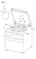
- FIG. 1 is a perspective view showing a centrifuge to which a filter device according to one embodiment is attached.
- FIG. 2 is a perspective view showing the filter device.
- FIG. 3 is a plan view showing the internal structure of the filter device.
- FIG. 4 is a plan view showing the internal structure of a filter device according to a modified example.
- FIG. 1 is a perspective view showing a centrifuge 50 to which a filter device 10 according to the present embodiment is attached.
- the filter device 10, an insert unit 60, and the centrifuge 50 are shown in Fig. 1.
- the centrifuge 50 is a machine that performs centrifugation on blood.
- the centrifuge 50 is equipped with a centrifugal drum 52.
- the centrifuge drum 52 is equipped with a central body 52a and multiple unit insertion portions 52b.
- the multiple unit insertion sections 52b are arranged to surround the central body 52a.
- An insert unit 60 can be inserted into each of the multiple unit insertion sections 52b. By inserting the insert unit 60 into the unit insertion section 52b, the insert unit 60 is attached to the centrifuge 50.
- the insert unit 60 houses a blood bag system (not shown).
- the blood bag system includes a blood bag that contains blood before it is centrifuged.
- the blood contained in this blood bag is, for example, whole blood, but it may also be a buffy coat as described in the above-mentioned Patent Publication No. 5223006.
- the buffy coat contains red blood cells, platelets, white blood cells, etc.
- the centrifuge 50 rotates the insert unit 60 inserted into the unit insertion section 52b around the central body 52a. More specifically, the centrifuge 50 rotates the insert unit 60 inserted into the unit insertion section 52b in the rotation direction DR around the rotation center line (center of rotation) LA shown in FIG. 1. This applies centrifugal force to the entire insert unit 60. This centrifugal force causes the blood to be centrifuged.
- the rotation center line LA is, for example, along the direction of gravity (the second direction D2 described below).
- the filter device 10 is attached to the insert unit 60.
- the filter device 10 is attached to the upper part of the insert unit 60, for example, but is not limited to this.
- the filter device 10 is attached to the insert unit 60, and is then attached to the centrifuge 50 via the insert unit 60.
- the above-mentioned centrifugal force is applied not only to the insert unit 60, but also to the filter device 10.
- the filter device 10 may also be attached directly to the centrifuge 50.
- FIG. 2 is a perspective view showing the filter device 10.
- the filter device 10 can be attached to the centrifuge 50.
- the configuration of the filter device 10 will be described on the assumption that the filter device 10 is attached to the centrifuge 50.
- the centrifugal direction DC, the centripetal direction DC-, the first direction D1, and the second direction D2 are shown in FIG. 2.
- the centrifugal direction DC is the direction of the centrifugal force applied to the filter device 10 by the centrifuge 50.
- the first direction D1 is the direction of the tangential velocity in the circular motion of the filter device 10 performed by the centrifuge 50.
- the first direction D1 is perpendicular (intersects) to the centrifugal direction DC.
- the second direction D2 is the direction of gravity.
- the centrifugal direction DC and the first direction D1 are perpendicular to the second direction D2.
- the centripetal direction DC- is the opposite direction to the centrifugal direction DC.
- the filter device 10 includes a housing 12.
- the housing 12 may be formed, for example, in a box shape.
- the thickness direction of the housing 12 coincides with the second direction D2.
- the housing 12 has an inlet portion 14 and an outlet portion 16.
- the inlet portion 14 has an inlet port 14a.
- the outlet portion 16 has an outlet port 16a.
- the inlet port 14a and the outlet port 16a are each an opening that connects the inside and outside of the housing 12.
- the inlet portion 14 and the outlet portion 16 shown in FIG. 2 protrude from the housing 12, but are not limited to this.
- the blood bag connected to the inlet 14 is a blood bag that already contains blood before it is centrifuged.
- the blood bag connected to the outlet 16 is a blood bag for containing blood (blood components) that has passed through the filter device 10.
- Figure 3 is a plan view showing the internal structure of the filter device 10.
- the housing 12 further includes an inflow passage 25, a first space 18, a second space 20, a partition wall 22, a leukocyte removal filter 24, and a communication port 28.
- the inflow passage 25, the first space 18, the second space 20, the partition wall 22, and the communication port 28 are provided within the housing 12.
- the leukocyte removal filter 24 is disposed in the second space 20.
- the first space 18 is located in the centrifugal direction DC with respect to the inflow passage 25 and the second space 20.
- the inflow passage 25 and the second space 20 are located between the first space 18 and the center of rotation LA ( Figure 1) of the centrifuge 50.
- the second space 20 is located in the first direction D1 with respect to the inflow passage 25.
- the partition 22 separates the first space 18 from the second space 20, and also separates the second space 20 from the inflow passage 25. More specifically, the partition 22 has a first wall portion 221 along the first direction D1 and a second wall portion 222 along the centrifugal direction DC. The first wall portion 221 separates the first space 18 from the second space 20. The second wall portion 222 separates the second space 20 from the inflow passage 25.
- the inflow flow path 25 is a flow path that reaches the first space 18 from the inlet 14a.
- the inflow flow path 25 extends along the centrifugal direction DC. Blood flows into the inflow flow path 25 via the inlet 14a.
- the inlet 14a is formed along the centrifugal direction DC. In this case, the centrifugal force applied by the centrifuge 50 causes the blood to flow smoothly through the inlet 14a and into the first space 18.
- the first space 18 has a first portion 181 and a second portion 182.
- the first portion 181 is located on one side of the center line C18.
- the second portion 182 is located on the other side of the center line C18.
- the center line C18 is an imaginary straight line that passes through the center of the first space 18 in the first direction D1 and is aligned with the centrifugal direction DC.
- the second portion 182 is located in the first direction D1 relative to the first portion 181.
- the first portion 181 of the first space 18 is connected to the inflow channel 25. Blood can flow along the inflow channel 25 into the first portion 181 of the first space 18 (FL1).
- the first space 18 is provided with a curved wall 26.
- the curved wall 26 is a part of the inner wall that defines the first space 18.
- the inlet flow passage 25 (inlet 14a) and the communication port 28 are located between the center of rotation LA ( Figure 1) of the centrifuge 50 and the curved wall 26.
- the curved wall 26 is curved to guide blood from the first portion 181 toward the second portion 182. This allows blood that has flowed into the first portion 181 via the inflow flow path 25 to flow along the curved wall 26 toward the second portion 182 without flowing back toward the inlet 14a (FL2, FL3).
- the blood that has flowed into the first space 18 is centrifuged by the centrifuge 50.
- the blood in the first space 18 forms a layer of supernatant liquid and a layer of sediment liquid.
- the layer of sediment liquid is located in the centrifugal direction DC relative to the layer of supernatant liquid.
- the main component of the sedimentation liquid is white blood cells.
- White blood cells are the main component of the sedimentation liquid because they are a relatively heavy blood component.
- white blood cells are a blood component that settles relatively easily, and therefore are the main component of the sedimentation liquid.
- the supernatant liquid contains blood components that are lighter than white blood cells.
- the supernatant liquid contains a large amount of platelets, etc.
- the white blood cells contained in the blood that has flowed into the first space 18 are collected on the centrifugal direction DC side of the first space 18 by the centrifugal force applied by the centrifuge 50 (FL2). Meanwhile, blood components other than the white blood cells are collected on the centripetal direction DC- side of the first space 18 (FL3).
- the communication opening 28 is an opening that communicates the first space 18 and the second space 20.
- the communication opening 28 is located between the first space 18 and the second space 20. As shown in FIG. 3, the second space 20 is located in the centripetal direction DC- with respect to the first space 18. Therefore, the communication opening 28 is located in the centripetal direction DC- with respect to the first space 18.
- the communication opening 28 is formed, for example, in the first wall portion 221 of the partition wall 22, but is not limited to this.
- the blood that has flowed into the first space 18 can flow into the second space 20 via the communication port 28 (FL4).
- blood components other than white blood cells are collected on the centripetal direction DC- side of the first space 18. Therefore, blood components other than white blood cells tend to flow into the second space 20 via the communication port 28. In other words, white blood cells do not easily flow into the second space 20.
- the inlet 14a (inlet flow passage 25) is connected to the first portion 181 of the first space 18.
- the communication port 28 is connected to the second portion 182 of the first space 18. In this way, blood flowing due to centrifugal force can be prevented from immediately flowing from the inlet 14a to the communication port 28. In other words, it is possible to prevent the blood flowing from the inlet 14a from reaching the communication port 28 before being separated into the sediment and supernatant liquid described above.
- the leukocyte removal filter 24 is disposed in the second space 20.
- the leukocyte removal filter 24 is equipped with a filter material for removing leukocytes from blood.
- the blood that flows into the second space 20 is filtered by the leukocyte removal filter 24.
- the leukocytes are removed by the leukocyte removal filter 24.
- the second space 20 is provided with an outflow section 16.
- the outflow section 16 is provided with an outlet 16a. Therefore, blood in the second space 20 can flow out of the housing 12 via the outlet 16a (FL5).
- the outlet 16a is located between the communication port 28 and the center of rotation LA (FIG. 1) of the centrifuge 50. In this way, it is possible to prevent white blood cells that have flowed into the second space 20 from reaching the outlet 16a. In other words, in order for blood that has flowed into the second space 20 to reach the outlet 16a, it must flow in the centripetal direction DC- from the communication port 28. As described above, when centrifugation is performed by the centrifuge 50, white blood cells are unlikely to flow in the centripetal direction DC-. By making the direction from the outlet 16a toward the communication port 28 the centrifugal direction DC as shown in FIG. 3, it is possible to prevent white blood cells from reaching the outlet 16a. This makes it possible to more suitably reduce the amount of white blood cells contained in the blood taken out from the outlet 16a.
- the second space 20 has a first portion 201 and a second portion 202.
- the first portion 201 is located on one side of the center line C20.
- the second portion 202 is located on the other side of the center line C20.
- the center line C20 is an imaginary straight line that passes through the center of the second space 20 in the first direction D1 and is aligned with the centrifugal direction DC.
- the second portion 202 is located in the first direction D1 relative to the first portion 201.
- the communication port 28 is connected to the second portion 202 of the second space 20.
- the outlet 16a is connected to the first portion 201 of the second space 20. In this way, a sufficiently long blood movement path can be secured within the leukocyte removal filter 24. This makes it possible to more reliably remove leukocytes using the leukocyte removal filter 24.
- the blood that flows into the first space 18 is centrifuged by the centrifuge 50. This reduces the amount of white blood cells contained in the blood that flows into the second space 20.
- the white blood cells remaining in the blood that flows into the second space 20 are removed by the white blood cell removal filter 24.
- FIG. 4 is a plan view showing the internal structure of a modified filter device 10 (10A).
- the first space 18 may be provided with a guide wall 32 that guides blood flowing in through the inlet 14a in the centrifugal direction DC.
- the guide wall 32 is located between the communication port 28 and the inlet 14a (inlet flow path 25) in the first direction D1.
- the guide wall 32 extends, for example, in the centrifugal direction DC and further in the first direction D1.
- the guide wall 32 prevents blood that has flowed into the first space 18 from immediately reaching the communication port 28 along the first direction D1 (FL6). In other words, blood that has flowed into the first space 18 from the inlet 14a cannot reach the communication port 28 unless it detours around the guide wall 32. This makes it possible to prevent blood that has not yet been centrifuged in the first space 18 from immediately reaching the communication port 28.
- the communication port 28 may be located in the first portion 181 of the first space 18.
- the guide wall 32 may prevent blood that has flowed into the first space 18 from immediately reaching the communication port 28 along the first direction D1.
- the communication port 28 located in the first portion 181 of the first space 18 can be connected to the first portion 201 of the second space 20. In such a case, it is preferable to position the outlet 16a in the second portion 202 of the second space 20. In this way, a sufficiently long blood movement path can be secured within the leukocyte removal filter 24. This makes it possible to more reliably remove leukocytes using the leukocyte removal filter 24.
- the present invention is not limited to the above disclosure, and various configurations may be adopted without departing from the gist of the present invention.
Landscapes
- Health & Medical Sciences (AREA)
- Heart & Thoracic Surgery (AREA)
- Vascular Medicine (AREA)
- Engineering & Computer Science (AREA)
- Anesthesiology (AREA)
- Biomedical Technology (AREA)
- Hematology (AREA)
- Life Sciences & Earth Sciences (AREA)
- Animal Behavior & Ethology (AREA)
- General Health & Medical Sciences (AREA)
- Public Health (AREA)
- Veterinary Medicine (AREA)
- Pathology (AREA)
- External Artificial Organs (AREA)
- Centrifugal Separators (AREA)
Abstract
Description
一実施形態によるフィルタ装置について図面を用いて説明する。図1は、本実施形態に係るフィルタ装置10が装着される遠心分離機50を示す斜視図である。フィルタ装置10と、インサートユニット60と、遠心分離機50とが、図1には示されている。
上記実施形態に係る変形例が以下に記載される。ただし、上記実施形態と重複する説明は適宜省略される。上記実施形態で説明済みの要素には、特に断らない限り、上記実施形態と同一の参照符号が付される。
Claims (8)
- 遠心分離機に装着されるフィルタ装置であって、
ハウジング内に形成されるとともに、流入口を介して血液が流入する第1空間と、
前記ハウジング内に形成されるとともに、流出口を介して血液が流出する第2空間と、
前記第1空間と前記第2空間とを隔てる隔壁と、
前記第1空間と前記第2空間とを連通する連通口と、
前記第2空間内に配され、前記血液に含まれる白血球を除去する白血球除去フィルタと、
を備え、
前記第2空間は、前記第1空間と、前記遠心分離機の回転中心との間に位置する、フィルタ装置。 - 請求項1に記載のフィルタ装置において、
前記流入口は、遠心力が付与される方向である遠心方向と交差する第1方向における前記第1空間の一方側に位置しており、
前記連通口は、前記第1方向における前記第1空間の他方側に位置する、フィルタ装置。 - 請求項2に記載のフィルタ装置において、
前記流出口は、前記第1方向における前記第2空間の一方側に位置しており、
前記連通口は、前記第1方向における前記第2空間の他方側に位置する、フィルタ装置。 - 請求項1に記載のフィルタ装置において、
前記第1空間には、前記流入口を介して流入する前記血液を遠心力が付与される方向である遠心方向に案内する案内壁が備えられる、フィルタ装置。 - 請求項4に記載のフィルタ装置において、
前記流入口と前記連通口とは、遠心力が付与される方向である遠心方向と交差する第1方向における前記第1空間の一方側に位置している、フィルタ装置。 - 請求項5に記載のフィルタ装置において、
前記連通口は、前記第1方向における前記第2空間の一方側に位置しており、
前記流出口は、前記第1方向における前記第2空間の他方側に位置する、フィルタ装置。 - 請求項1に記載のフィルタ装置において、
前記第1空間には、曲壁が備えられ、
前記遠心分離機の回転中心と、前記曲壁との間に、前記流入口と前記連通口とが位置する、フィルタ装置。 - 請求項1に記載のフィルタ装置において、
前記流入口から前記第1空間に達するとともに、前記第2空間とは隔てられた流入流路が、前記ハウジング内に形成され、
前記流入流路は、遠心力が付与される方向である遠心方向に沿って延在する、フィルタ装置。
Priority Applications (4)
| Application Number | Priority Date | Filing Date | Title |
|---|---|---|---|
| EP24823493.2A EP4721777A1 (en) | 2023-06-16 | 2024-06-17 | Filter device |
| CN202480028724.9A CN121127282A (zh) | 2023-06-16 | 2024-06-17 | 过滤装置 |
| JP2025528038A JPWO2024257880A1 (ja) | 2023-06-16 | 2024-06-17 | |
| US19/420,209 US20260144919A1 (en) | 2023-06-16 | 2025-12-15 | Filter device |
Applications Claiming Priority (2)
| Application Number | Priority Date | Filing Date | Title |
|---|---|---|---|
| JP2023-099351 | 2023-06-16 | ||
| JP2023099351 | 2023-06-16 |
Related Child Applications (1)
| Application Number | Title | Priority Date | Filing Date |
|---|---|---|---|
| US19/420,209 Continuation US20260144919A1 (en) | 2023-06-16 | 2025-12-15 | Filter device |
Publications (1)
| Publication Number | Publication Date |
|---|---|
| WO2024257880A1 true WO2024257880A1 (ja) | 2024-12-19 |
Family
ID=93852166
Family Applications (1)
| Application Number | Title | Priority Date | Filing Date |
|---|---|---|---|
| PCT/JP2024/021795 Ceased WO2024257880A1 (ja) | 2023-06-16 | 2024-06-17 | フィルタ装置 |
Country Status (5)
| Country | Link |
|---|---|
| US (1) | US20260144919A1 (ja) |
| EP (1) | EP4721777A1 (ja) |
| JP (1) | JPWO2024257880A1 (ja) |
| CN (1) | CN121127282A (ja) |
| WO (1) | WO2024257880A1 (ja) |
Citations (6)
| Publication number | Priority date | Publication date | Assignee | Title |
|---|---|---|---|---|
| JPH01249063A (ja) * | 1988-02-17 | 1989-10-04 | Pall Corp | 血小板濃縮液から白血球を分離する装置および方法 |
| JPH06245998A (ja) * | 1993-02-22 | 1994-09-06 | Asahi Medical Co Ltd | 白血球除去フィルター支持体 |
| JP2005052239A (ja) * | 2003-08-08 | 2005-03-03 | Terumo Corp | 血液成分採取回路 |
| JP2005523080A (ja) * | 2002-04-16 | 2005-08-04 | ガンブロ インコーポレーテッド | 血液成分処理システム、装置、および方法 |
| JP2006158738A (ja) * | 2004-12-08 | 2006-06-22 | Asahi Kasei Medical Co Ltd | 白血球除去システムの遠心方法 |
| JP5223006B2 (ja) | 2008-11-28 | 2013-06-26 | テルモ株式会社 | 血液バッグシステム及びカセット |
-
2024
- 2024-06-17 CN CN202480028724.9A patent/CN121127282A/zh active Pending
- 2024-06-17 JP JP2025528038A patent/JPWO2024257880A1/ja active Pending
- 2024-06-17 EP EP24823493.2A patent/EP4721777A1/en active Pending
- 2024-06-17 WO PCT/JP2024/021795 patent/WO2024257880A1/ja not_active Ceased
-
2025
- 2025-12-15 US US19/420,209 patent/US20260144919A1/en active Pending
Patent Citations (6)
| Publication number | Priority date | Publication date | Assignee | Title |
|---|---|---|---|---|
| JPH01249063A (ja) * | 1988-02-17 | 1989-10-04 | Pall Corp | 血小板濃縮液から白血球を分離する装置および方法 |
| JPH06245998A (ja) * | 1993-02-22 | 1994-09-06 | Asahi Medical Co Ltd | 白血球除去フィルター支持体 |
| JP2005523080A (ja) * | 2002-04-16 | 2005-08-04 | ガンブロ インコーポレーテッド | 血液成分処理システム、装置、および方法 |
| JP2005052239A (ja) * | 2003-08-08 | 2005-03-03 | Terumo Corp | 血液成分採取回路 |
| JP2006158738A (ja) * | 2004-12-08 | 2006-06-22 | Asahi Kasei Medical Co Ltd | 白血球除去システムの遠心方法 |
| JP5223006B2 (ja) | 2008-11-28 | 2013-06-26 | テルモ株式会社 | 血液バッグシステム及びカセット |
Also Published As
| Publication number | Publication date |
|---|---|
| JPWO2024257880A1 (ja) | 2024-12-19 |
| EP4721777A1 (en) | 2026-04-08 |
| CN121127282A (zh) | 2025-12-12 |
| US20260144919A1 (en) | 2026-05-28 |
Similar Documents
| Publication | Publication Date | Title |
|---|---|---|
| JP5546038B2 (ja) | 3−ラインアフェレーシスシステム及び方法 | |
| JP3313572B2 (ja) | 血液処理用遠心分離器ボウル | |
| JP4964627B2 (ja) | 流体成分を分離するための方法 | |
| US8348823B2 (en) | Disposable device for the continuous centrifugal separation of a physiological fluid | |
| CA2547905C (en) | Separation apparatus and method | |
| US8226537B2 (en) | Blood processing apparatus with cell separation chamber with baffles | |
| US5224921A (en) | Small volume collection chamber | |
| AU2008258520B2 (en) | Cartridge and Centrifuge having a Cartridge | |
| EP2717942B1 (en) | System for blood separation with gravity valve for controlling a side-tapped separation chamber | |
| US20080128367A1 (en) | Method and Disposable Device For Blood Centrifugal Separation | |
| JP6708650B2 (ja) | 血小板の採取方法及びその採取システム | |
| JP2010528739A (ja) | カートリッジおよびカートリッジを有する遠心分離器 | |
| US20090065424A1 (en) | Circular centrifugation chamber for separation of blood | |
| CN103974777A (zh) | 可迅速离心分离的离心分离用容器 | |
| EP2590697B1 (en) | System for blood separation with side-tapped separation chamber | |
| WO2024257879A1 (ja) | フィルタ装置 | |
| WO2024257881A1 (ja) | フィルタ装置 | |
| EP4721777A1 (en) | Filter device | |
| US20120015795A1 (en) | Centrifuge for processing blood and blood components | |
| JP7807428B2 (ja) | 血液バッグシステム及び血液の処理方法 | |
| JP7382711B2 (ja) | 細胞成分採取システムおよび細胞成分採取方法 | |
| JPH0236619Y2 (ja) | ||
| JP7140755B2 (ja) | 血小板分離器、血小板回収装置、血小板採取システム及び血小板採取方法 | |
| JP6760944B2 (ja) | 血小板の分離器及び血小板の回収装置 |
Legal Events
| Date | Code | Title | Description |
|---|---|---|---|
| 121 | Ep: the epo has been informed by wipo that ep was designated in this application |
Ref document number: 24823493 Country of ref document: EP Kind code of ref document: A1 |
|
| ENP | Entry into the national phase |
Ref document number: 2025528038 Country of ref document: JP Kind code of ref document: A |
|
| WWE | Wipo information: entry into national phase |
Ref document number: 2025528038 Country of ref document: JP |
|
| WWE | Wipo information: entry into national phase |
Ref document number: 2024823493 Country of ref document: EP |
|
| NENP | Non-entry into the national phase |
Ref country code: DE |
|
| ENP | Entry into the national phase |
Ref document number: 2024823493 Country of ref document: EP Effective date: 20260102 |
|
| ENP | Entry into the national phase |
Ref document number: 2024823493 Country of ref document: EP Effective date: 20260102 |
|
| ENP | Entry into the national phase |
Ref document number: 2024823493 Country of ref document: EP Effective date: 20260102 |
|
| ENP | Entry into the national phase |
Ref document number: 2024823493 Country of ref document: EP Effective date: 20260102 |
|
| WWP | Wipo information: published in national office |
Ref document number: 2024823493 Country of ref document: EP |