WO2024261952A1 - 切削工具 - Google Patents
切削工具 Download PDFInfo
- Publication number
- WO2024261952A1 WO2024261952A1 PCT/JP2023/023097 JP2023023097W WO2024261952A1 WO 2024261952 A1 WO2024261952 A1 WO 2024261952A1 JP 2023023097 W JP2023023097 W JP 2023023097W WO 2024261952 A1 WO2024261952 A1 WO 2024261952A1
- Authority
- WO
- WIPO (PCT)
- Prior art keywords
- layer
- cutting tool
- residual stress
- less
- substrate
- Prior art date
- Legal status (The legal status is an assumption and is not a legal conclusion. Google has not performed a legal analysis and makes no representation as to the accuracy of the status listed.)
- Ceased
Links
Images

Classifications
-
- B—PERFORMING OPERATIONS; TRANSPORTING
- B23—MACHINE TOOLS; METAL-WORKING NOT OTHERWISE PROVIDED FOR
- B23B—TURNING; BORING
- B23B27/00—Tools for turning or boring machines; Tools of a similar kind in general; Accessories therefor
- B23B27/14—Cutting tools of which the bits or tips or cutting inserts are of special material
- B23B27/148—Composition of the cutting inserts
-
- C—CHEMISTRY; METALLURGY
- C23—COATING METALLIC MATERIAL; COATING MATERIAL WITH METALLIC MATERIAL; CHEMICAL SURFACE TREATMENT; DIFFUSION TREATMENT OF METALLIC MATERIAL; COATING BY VACUUM EVAPORATION, BY SPUTTERING, BY ION IMPLANTATION OR BY CHEMICAL VAPOUR DEPOSITION, IN GENERAL; INHIBITING CORROSION OF METALLIC MATERIAL OR INCRUSTATION IN GENERAL
- C23C—COATING METALLIC MATERIAL; COATING MATERIAL WITH METALLIC MATERIAL; SURFACE TREATMENT OF METALLIC MATERIAL BY DIFFUSION INTO THE SURFACE, BY CHEMICAL CONVERSION OR SUBSTITUTION; COATING BY VACUUM EVAPORATION, BY SPUTTERING, BY ION IMPLANTATION OR BY CHEMICAL VAPOUR DEPOSITION, IN GENERAL
- C23C16/00—Chemical coating by decomposition of gaseous compounds, without leaving reaction products of surface material in the coating, i.e. chemical vapour deposition [CVD] processes
- C23C16/22—Chemical coating by decomposition of gaseous compounds, without leaving reaction products of surface material in the coating, i.e. chemical vapour deposition [CVD] processes characterised by the deposition of inorganic material, other than metallic material
- C23C16/30—Deposition of compounds, mixtures or solid solutions, e.g. borides, carbides, nitrides
- C23C16/36—Carbonitrides
-
- C—CHEMISTRY; METALLURGY
- C23—COATING METALLIC MATERIAL; COATING MATERIAL WITH METALLIC MATERIAL; CHEMICAL SURFACE TREATMENT; DIFFUSION TREATMENT OF METALLIC MATERIAL; COATING BY VACUUM EVAPORATION, BY SPUTTERING, BY ION IMPLANTATION OR BY CHEMICAL VAPOUR DEPOSITION, IN GENERAL; INHIBITING CORROSION OF METALLIC MATERIAL OR INCRUSTATION IN GENERAL
- C23C—COATING METALLIC MATERIAL; COATING MATERIAL WITH METALLIC MATERIAL; SURFACE TREATMENT OF METALLIC MATERIAL BY DIFFUSION INTO THE SURFACE, BY CHEMICAL CONVERSION OR SUBSTITUTION; COATING BY VACUUM EVAPORATION, BY SPUTTERING, BY ION IMPLANTATION OR BY CHEMICAL VAPOUR DEPOSITION, IN GENERAL
- C23C16/00—Chemical coating by decomposition of gaseous compounds, without leaving reaction products of surface material in the coating, i.e. chemical vapour deposition [CVD] processes
- C23C16/22—Chemical coating by decomposition of gaseous compounds, without leaving reaction products of surface material in the coating, i.e. chemical vapour deposition [CVD] processes characterised by the deposition of inorganic material, other than metallic material
- C23C16/30—Deposition of compounds, mixtures or solid solutions, e.g. borides, carbides, nitrides
- C23C16/40—Oxides
- C23C16/403—Oxides of aluminium, magnesium or beryllium
-
- C—CHEMISTRY; METALLURGY
- C23—COATING METALLIC MATERIAL; COATING MATERIAL WITH METALLIC MATERIAL; CHEMICAL SURFACE TREATMENT; DIFFUSION TREATMENT OF METALLIC MATERIAL; COATING BY VACUUM EVAPORATION, BY SPUTTERING, BY ION IMPLANTATION OR BY CHEMICAL VAPOUR DEPOSITION, IN GENERAL; INHIBITING CORROSION OF METALLIC MATERIAL OR INCRUSTATION IN GENERAL
- C23C—COATING METALLIC MATERIAL; COATING MATERIAL WITH METALLIC MATERIAL; SURFACE TREATMENT OF METALLIC MATERIAL BY DIFFUSION INTO THE SURFACE, BY CHEMICAL CONVERSION OR SUBSTITUTION; COATING BY VACUUM EVAPORATION, BY SPUTTERING, BY ION IMPLANTATION OR BY CHEMICAL VAPOUR DEPOSITION, IN GENERAL
- C23C16/00—Chemical coating by decomposition of gaseous compounds, without leaving reaction products of surface material in the coating, i.e. chemical vapour deposition [CVD] processes
- C23C16/44—Chemical coating by decomposition of gaseous compounds, without leaving reaction products of surface material in the coating, i.e. chemical vapour deposition [CVD] processes characterised by the method of coating
- C23C16/455—Chemical coating by decomposition of gaseous compounds, without leaving reaction products of surface material in the coating, i.e. chemical vapour deposition [CVD] processes characterised by the method of coating characterised by the method used for introducing gases into reaction chamber or for modifying gas flows in reaction chamber
- C23C16/45502—Flow conditions in reaction chamber
- C23C16/45508—Radial flow
-
- C—CHEMISTRY; METALLURGY
- C23—COATING METALLIC MATERIAL; COATING MATERIAL WITH METALLIC MATERIAL; CHEMICAL SURFACE TREATMENT; DIFFUSION TREATMENT OF METALLIC MATERIAL; COATING BY VACUUM EVAPORATION, BY SPUTTERING, BY ION IMPLANTATION OR BY CHEMICAL VAPOUR DEPOSITION, IN GENERAL; INHIBITING CORROSION OF METALLIC MATERIAL OR INCRUSTATION IN GENERAL
- C23C—COATING METALLIC MATERIAL; COATING MATERIAL WITH METALLIC MATERIAL; SURFACE TREATMENT OF METALLIC MATERIAL BY DIFFUSION INTO THE SURFACE, BY CHEMICAL CONVERSION OR SUBSTITUTION; COATING BY VACUUM EVAPORATION, BY SPUTTERING, BY ION IMPLANTATION OR BY CHEMICAL VAPOUR DEPOSITION, IN GENERAL
- C23C16/00—Chemical coating by decomposition of gaseous compounds, without leaving reaction products of surface material in the coating, i.e. chemical vapour deposition [CVD] processes
- C23C16/56—After-treatment
-
- C—CHEMISTRY; METALLURGY
- C23—COATING METALLIC MATERIAL; COATING MATERIAL WITH METALLIC MATERIAL; CHEMICAL SURFACE TREATMENT; DIFFUSION TREATMENT OF METALLIC MATERIAL; COATING BY VACUUM EVAPORATION, BY SPUTTERING, BY ION IMPLANTATION OR BY CHEMICAL VAPOUR DEPOSITION, IN GENERAL; INHIBITING CORROSION OF METALLIC MATERIAL OR INCRUSTATION IN GENERAL
- C23C—COATING METALLIC MATERIAL; COATING MATERIAL WITH METALLIC MATERIAL; SURFACE TREATMENT OF METALLIC MATERIAL BY DIFFUSION INTO THE SURFACE, BY CHEMICAL CONVERSION OR SUBSTITUTION; COATING BY VACUUM EVAPORATION, BY SPUTTERING, BY ION IMPLANTATION OR BY CHEMICAL VAPOUR DEPOSITION, IN GENERAL
- C23C28/00—Coating for obtaining at least two superposed coatings either by methods not provided for in a single one of groups C23C2/00 - C23C26/00 or by combinations of methods provided for in subclasses C23C and C25C or C25D
- C23C28/04—Coating for obtaining at least two superposed coatings either by methods not provided for in a single one of groups C23C2/00 - C23C26/00 or by combinations of methods provided for in subclasses C23C and C25C or C25D only coatings of inorganic non-metallic material
-
- C—CHEMISTRY; METALLURGY
- C23—COATING METALLIC MATERIAL; COATING MATERIAL WITH METALLIC MATERIAL; CHEMICAL SURFACE TREATMENT; DIFFUSION TREATMENT OF METALLIC MATERIAL; COATING BY VACUUM EVAPORATION, BY SPUTTERING, BY ION IMPLANTATION OR BY CHEMICAL VAPOUR DEPOSITION, IN GENERAL; INHIBITING CORROSION OF METALLIC MATERIAL OR INCRUSTATION IN GENERAL
- C23C—COATING METALLIC MATERIAL; COATING MATERIAL WITH METALLIC MATERIAL; SURFACE TREATMENT OF METALLIC MATERIAL BY DIFFUSION INTO THE SURFACE, BY CHEMICAL CONVERSION OR SUBSTITUTION; COATING BY VACUUM EVAPORATION, BY SPUTTERING, BY ION IMPLANTATION OR BY CHEMICAL VAPOUR DEPOSITION, IN GENERAL
- C23C28/00—Coating for obtaining at least two superposed coatings either by methods not provided for in a single one of groups C23C2/00 - C23C26/00 or by combinations of methods provided for in subclasses C23C and C25C or C25D
- C23C28/04—Coating for obtaining at least two superposed coatings either by methods not provided for in a single one of groups C23C2/00 - C23C26/00 or by combinations of methods provided for in subclasses C23C and C25C or C25D only coatings of inorganic non-metallic material
- C23C28/042—Coating for obtaining at least two superposed coatings either by methods not provided for in a single one of groups C23C2/00 - C23C26/00 or by combinations of methods provided for in subclasses C23C and C25C or C25D only coatings of inorganic non-metallic material including a refractory ceramic layer, e.g. refractory metal oxides, ZrO2, rare earth oxides
-
- C—CHEMISTRY; METALLURGY
- C23—COATING METALLIC MATERIAL; COATING MATERIAL WITH METALLIC MATERIAL; CHEMICAL SURFACE TREATMENT; DIFFUSION TREATMENT OF METALLIC MATERIAL; COATING BY VACUUM EVAPORATION, BY SPUTTERING, BY ION IMPLANTATION OR BY CHEMICAL VAPOUR DEPOSITION, IN GENERAL; INHIBITING CORROSION OF METALLIC MATERIAL OR INCRUSTATION IN GENERAL
- C23C—COATING METALLIC MATERIAL; COATING MATERIAL WITH METALLIC MATERIAL; SURFACE TREATMENT OF METALLIC MATERIAL BY DIFFUSION INTO THE SURFACE, BY CHEMICAL CONVERSION OR SUBSTITUTION; COATING BY VACUUM EVAPORATION, BY SPUTTERING, BY ION IMPLANTATION OR BY CHEMICAL VAPOUR DEPOSITION, IN GENERAL
- C23C28/00—Coating for obtaining at least two superposed coatings either by methods not provided for in a single one of groups C23C2/00 - C23C26/00 or by combinations of methods provided for in subclasses C23C and C25C or C25D
- C23C28/04—Coating for obtaining at least two superposed coatings either by methods not provided for in a single one of groups C23C2/00 - C23C26/00 or by combinations of methods provided for in subclasses C23C and C25C or C25D only coatings of inorganic non-metallic material
- C23C28/044—Coating for obtaining at least two superposed coatings either by methods not provided for in a single one of groups C23C2/00 - C23C26/00 or by combinations of methods provided for in subclasses C23C and C25C or C25D only coatings of inorganic non-metallic material coatings specially adapted for cutting tools or wear applications
-
- C—CHEMISTRY; METALLURGY
- C23—COATING METALLIC MATERIAL; COATING MATERIAL WITH METALLIC MATERIAL; CHEMICAL SURFACE TREATMENT; DIFFUSION TREATMENT OF METALLIC MATERIAL; COATING BY VACUUM EVAPORATION, BY SPUTTERING, BY ION IMPLANTATION OR BY CHEMICAL VAPOUR DEPOSITION, IN GENERAL; INHIBITING CORROSION OF METALLIC MATERIAL OR INCRUSTATION IN GENERAL
- C23C—COATING METALLIC MATERIAL; COATING MATERIAL WITH METALLIC MATERIAL; SURFACE TREATMENT OF METALLIC MATERIAL BY DIFFUSION INTO THE SURFACE, BY CHEMICAL CONVERSION OR SUBSTITUTION; COATING BY VACUUM EVAPORATION, BY SPUTTERING, BY ION IMPLANTATION OR BY CHEMICAL VAPOUR DEPOSITION, IN GENERAL
- C23C30/00—Coating with metallic material characterised only by the composition of the metallic material, i.e. not characterised by the coating process
- C23C30/005—Coating with metallic material characterised only by the composition of the metallic material, i.e. not characterised by the coating process on hard metal substrates
-
- B—PERFORMING OPERATIONS; TRANSPORTING
- B23—MACHINE TOOLS; METAL-WORKING NOT OTHERWISE PROVIDED FOR
- B23B—TURNING; BORING
- B23B2228/00—Properties of materials of tools or workpieces, materials of tools or workpieces applied in a specific manner
- B23B2228/10—Coatings
- B23B2228/105—Coatings with specified thickness
Definitions
- This disclosure relates to cutting tools.
- Patent Documents 1 to 6 cutting tools that have a substrate and a coating disposed on the substrate have been used for cutting.
- the cutting tool of the present disclosure comprises: 1.
- a cutting tool comprising a substrate and a coating disposed on the substrate, the coating includes a first layer disposed on the substrate, a second layer disposed on the first layer, and a third layer disposed on the second layer; the first layer being made of titanium carbonitride; the second layer is made of aluminum oxide; the third layer is made of titanium carbonitride;
- the residual stress X of the first layer and the residual stress Y of the second layer satisfy the relationship of Equation 1
- the residual stress Y of the second layer and the residual stress Z of the third layer satisfy the relationship of Equation 2.
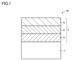
- FIG. 1 is a schematic cross-sectional view illustrating one embodiment of a cutting tool according to the present disclosure.
- FIG. 2 is a schematic cross-sectional view of an example of a CVD (Chemical Vapor Deposition) apparatus used in manufacturing the cutting tool of the present disclosure.
- CVD Chemical Vapor Deposition
- a cutting tool in high-speed turning of steel with a low carbon content, which includes a substrate and a coating disposed on the substrate, the coating including a first layer located on the substrate, a second layer located on the first layer, and a third layer located on the second layer, the first layer being made of titanium carbonitride, the second layer being made of aluminum oxide, and the third layer being made of titanium carbonitride.
- the residual stress of the first layer is difficult to be sufficiently reduced, and therefore the "fracture resistance” may not be sufficient.
- there are cases where wear is easily caused by micro-damage resulting from insufficient "fracture resistance” i.e., there are cases where "wear resistance” is insufficient). Therefore, there is a demand for a tool that combines excellent "wear resistance” and excellent “fracture resistance” to extend tool life, particularly in high-speed turning of steel with a low carbon content.
- the present disclosure therefore aims to provide a cutting tool that has a long tool life, especially in high-speed turning of steels with low carbon content.
- the cutting tool of the present disclosure comprises: 1.
- a cutting tool comprising a substrate and a coating disposed on the substrate, the coating includes a first layer disposed on the substrate, a second layer disposed on the first layer, and a third layer disposed on the second layer; the first layer is made of titanium carbonitride; the second layer is made of aluminum oxide; the third layer is made of titanium carbonitride;
- the residual stress X of the first layer and the residual stress Y of the second layer satisfy the relationship of Equation 1,
- the residual stress Y of the second layer and the residual stress Z of the third layer satisfy the relationship of Equation 2.
- the residual stress X of the first layer is preferably -1.0 GPa or more and -0.3 GPa or less. This makes it possible to provide a cutting tool with a longer tool life, especially in high-speed turning of steel with a low carbon content.
- the residual stress Y of the second layer is preferably -0.5 GPa or more and 0.1 GPa or less. This makes it possible to provide a cutting tool with a longer tool life, especially in high-speed turning of steel with a low carbon content.
- the residual stress Z of the third layer is preferably -1.0 GPa or more and -0.3 GPa or less. This makes it possible to provide a cutting tool with a longer tool life, especially in high-speed turning of steel with a low carbon content.
- the thickness of the first layer is preferably 3 ⁇ m or more and 15 ⁇ m or less. This makes it possible to provide a cutting tool with a longer tool life, especially in high-speed turning of steel with a low carbon content.
- the thickness of the second layer is preferably 3 ⁇ m or more and 15 ⁇ m or less. This makes it possible to provide a cutting tool with a longer tool life, especially in high-speed turning of steel with a low carbon content.
- the thickness of the third layer is preferably 2 ⁇ m or more and 4 ⁇ m or less. This makes it possible to provide a cutting tool with a longer tool life, especially in high-speed turning of steel with a low carbon content.
- a ⁇ B means the upper and lower limits of a range (i.e., greater than or equal to A and less than or equal to B). If no unit is stated for A and only a unit is stated for B, the units of A and B are the same.
- a cutting tool according to an embodiment of the present disclosure will be described with reference to FIG.
- One embodiment of the present disclosure (hereinafter also referred to as “the present embodiment") is A cutting tool 10 comprising a substrate 1 and a coating 2 disposed on the substrate 1,
- the coating 2 includes a first layer 3 located on the substrate 1, a second layer 4 located on the first layer 3, and a third layer 5 located on the second layer 4,
- the first layer 3 is made of titanium carbonitride
- the second layer 4 is made of aluminum oxide
- the third layer 5 is made of titanium carbonitride,
- the residual stress X of the first layer 3 and the residual stress Y of the second layer 4 satisfy the relationship of Equation 1
- the residual stress Y of the second layer 4 and the residual stress Z of the third layer 5 satisfy the relationship of Equation 2.
- the residual stress X of the first layer 3 and the residual stress Y of the second layer 4 satisfy the relationship of Equation 1
- the residual stress Y of the second layer 4 and the residual stress Z of the third layer 5 satisfy the relationship of Equation 2.
- X ⁇ Y Formula 1 Z ⁇ Y Equation 2 This can improve fracture resistance because the residual stress on the substrate 1 side of the coating 2 is relatively low relative to the residual stress on the surface side of the coating 2. Furthermore, because the residual stress in the region sandwiched between the region on the substrate 1 side of the coating 2 and the region on the surface side of the coating 2 is relatively high, it becomes easier to suppress falling off due to welding of the second layer 4, which contributes to suppressing the progress of wear, particularly in high-speed turning of steel with a low carbon content, so that wear resistance can be improved.
- cutting tool 1 can combine excellent "wear resistance” and excellent “fracture resistance,” making it possible to provide a cutting tool with a long tool life, especially in high-speed turning of steel with a low carbon content.
- a cutting tool 10 includes a substrate 1 and a coating 2 disposed on the substrate 1.
- the coating 2 preferably covers the entire surface of the substrate 1, but even if a part of the substrate 1 is not covered with the coating 2 or the configuration of the coating 2 is partially different, this does not deviate from the scope of this embodiment.
- the coating 2 is preferably disposed so as to cover at least the surface of the part of the substrate 1 involved in cutting.
- the part of the substrate 1 involved in cutting means, depending on the size and shape of the substrate 1, a region of the substrate 1 surrounded by the cutting edge ridge and a virtual surface whose distance from the cutting edge ridge to the substrate 1 side along the perpendicular to the tangent to the cutting edge ridge is, for example, 5 mm, 3 mm, 2 mm, 1 mm, or 0.5 mm.
- the cutting tool 10 of this embodiment can be suitably used as a cutting tool 10 such as a drill, an end mill, an indexable cutting tip for a drill, an indexable cutting tip for an end mill, an indexable cutting tip for milling, an indexable cutting tip for turning, a metal saw, a gear cutting tool, a reamer, and a tap.
- a cutting tool 10 such as a drill, an end mill, an indexable cutting tip for a drill, an indexable cutting tip for an end mill, an indexable cutting tip for milling, an indexable cutting tip for turning, a metal saw, a gear cutting tool, a reamer, and a tap.
- the substrate 1 is preferably any of the following: cemented carbide (WC-based cemented carbide, cemented carbide containing WC and Co, cemented carbide containing carbonitrides of Ti, Ta, Nb, etc.), cermet (mainly composed of TiC, TiN, TiCN, etc.), high-speed steel, ceramics (titanium carbide, silicon carbide, silicon nitride, aluminum nitride, aluminum oxide, etc.), cubic boron nitride sintered body, and diamond sintered body.
- cemented carbide WC-based cemented carbide, cemented carbide containing WC and Co, cemented carbide containing carbonitrides of Ti, Ta, Nb, etc.
- cermet mainly composed of TiC, TiN, TiCN, etc.
- high-speed steel ceramics (titanium carbide, silicon carbide, silicon nitride, aluminum nitride, aluminum oxide, etc.), cubic boron nitride sintered body, and diamond
- WC-based cemented carbide and cermets especially TiCN-based cermets.
- These substrates 1 have an excellent balance of hardness and strength, especially at high temperatures, and when used as the substrate 1 of a cutting tool 10, they can contribute to extending the life of the cutting tool 10.
- the coating 2 includes a first layer 3 located on the substrate 1, a second layer 4 located on the first layer 3, and a third layer 5 located on the second layer 4.
- the coating 2 has the effect of improving various properties of the cutting tool 10, such as wear resistance and chipping resistance, and thereby extending the life of the cutting tool 10.
- the coating 2 may include "other layers" (described later) in addition to the first layer 3, second layer 4, and third layer 5, as long as the effects of the present disclosure are not impaired.
- the thickness of the coating 2 is preferably 6 ⁇ m or more and 30 ⁇ m or less. If the thickness of the coating 2 is less than 6 ⁇ m, the life of the cutting tool 10 tends to be shortened due to the coating 2 being too thin. On the other hand, if the thickness of the coating 2 exceeds 30 ⁇ m, chipping of the coating 2 tends to occur in the early stage of cutting, and the life of the cutting tool 10 tends to be shortened.
- the thickness of the coating 3 can be measured by observing the cross section of the coating 2 using a scanning electron microscope (SEM).
- the observation magnification of the cross section sample is set to 5,000 to 10,000 times, the observation area is set to 100 to 500 ⁇ m2 , the thickness width is measured at three points in one field of view, and the average value is taken as the "thickness". The same applies to the thickness of each layer described below unless otherwise specified.
- the first layer 3 is made of titanium carbonitride.
- "made of titanium carbonitride” means that in addition to titanium carbonitride, inevitable impurities can be contained, as long as the effects of the present disclosure are exhibited.
- the inevitable impurities include chlorine atoms (Cl).
- the total content of inevitable impurities in the first layer 3 is preferably greater than 0 mass% and less than 3 mass%.
- the first layer 3 is made of titanium carbonitride is identified by X-ray diffraction (XRD) and energy dispersive X-ray analysis (EDX).
- XRD X-ray diffraction
- EDX energy dispersive X-ray analysis
- SIMS secondary ion mass spectrometry
- the thickness of the first layer 3 is preferably 3 ⁇ m or more and 15 ⁇ m or less. This allows both superior wear resistance and superior chipping resistance to be achieved, and therefore a cutting tool having a longer tool life can be provided, especially in high-speed turning of steel with a low carbon content.
- the lower limit of the thickness of the first layer 3 is preferably 3 ⁇ m or more, more preferably 5 ⁇ m or more, and even more preferably 7 ⁇ m or more.
- the upper limit of the thickness of the first layer 3 is preferably 15 ⁇ m or less, more preferably 13 ⁇ m or less, and even more preferably 11 ⁇ m or less.
- the thickness of the first layer 3 is more preferably 5 ⁇ m or more and 13 ⁇ m or less, and even more preferably 7 ⁇ m or more and 11 ⁇ m or less.
- the residual stress X of the first layer 3 is preferably -1.0 GPa or more and -0.3 GPa or less. This makes it easier to suppress the spread of damage when a minute chip occurs, so that a cutting tool having a longer tool life can be provided, especially in high-speed turning of steel with a low carbon content.
- the lower limit of the residual stress X of the first layer 3 is preferably -1.0 GPa or more, more preferably -0.9 GPa or more, and even more preferably -0.8 GPa or more.
- the upper limit of the residual stress X of the first layer 3 is preferably -0.3 GPa or less, more preferably -0.4 GPa or less, and even more preferably -0.5 GPa or less.
- the residual stress X of the first layer 3 is more preferably -0.9 GPa or more and -0.4 GPa or less, and even more preferably -0.8 GPa or more and -0.5 GPa or less.
- the residual stress X of the first layer 3 can be determined by measuring the first layer 3 using an X-ray residual stress device with the sin2 ⁇ method (see pages 54-66 of "X-Ray Stress Measurement Method" (Japan Society for Materials Science, published by Yokendo Co., Ltd. in 1981). The temperature during the measurement is room temperature (20°C). It has also been confirmed that there is no variation in the measurement results, even if the measurement location is arbitrarily selected, as long as the measurement is performed using the same cutting tool 10.
- the second layer 4 is made of aluminum oxide.
- "made of aluminum oxide” means that in addition to aluminum oxide, inevitable impurities can be contained, as long as the effect of the present disclosure is exhibited.
- the inevitable impurities include chlorine atoms (Cl).
- the total content of inevitable impurities in the second layer 4 is preferably greater than 0 mass% and less than 3 mass%.
- the second layer 4 is made of aluminum oxide is identified by X-ray diffraction (XRD) and energy dispersive X-ray analysis (EDX).
- XRD X-ray diffraction
- EDX energy dispersive X-ray analysis
- SIMS secondary ion mass spectrometry
- the thickness of the second layer 4 is preferably 3 ⁇ m or more and 15 ⁇ m or less. This makes it possible to achieve both better wear resistance and better chipping resistance, and therefore it is possible to provide a cutting tool with a longer tool life, especially in high-speed turning of steel with a low carbon content.
- the lower limit of the thickness of the second layer 4 is preferably 3 ⁇ m or more, more preferably 5 ⁇ m or more, and even more preferably 7 ⁇ m or more.
- the upper limit of the thickness of the second layer 4 is preferably 15 ⁇ m or less, more preferably 13 ⁇ m or less, and even more preferably 11 ⁇ m or less.
- the thickness of the second layer 4 is more preferably 5 ⁇ m or more and 13 ⁇ m or less, and even more preferably 7 ⁇ m or more and 11 ⁇ m or less.
- the residual stress Y of the second layer 4 is preferably -0.5 GPa or more and 0.1 GPa or less.
- the lower limit of the residual stress Y of the second layer 4 is preferably -0.5 GPa or more, more preferably -0.4 GPa or more, and even more preferably -0.3 GPa or more.
- the upper limit of the residual stress Y of the second layer 4 is preferably 0.1 GPa or less, more preferably 0 GPa or less, and even more preferably -0.1 GPa or less.
- the residual stress Y of the second layer 4 is more preferably -0.4 GPa or more and 0 GPa or less, and even more preferably -0.3 GPa or more and -0.1 GPa or less.
- the residual stress Y in the second layer 4 can be determined by a method similar to the method for measuring the residual stress X in the first layer 3, except that the measurement is performed on the second layer 4. It has been confirmed that, as long as the measurement is performed using the same cutting tool 10, there is no variation in the measurement results even if the measurement location is selected arbitrarily.
- the third layer 5 is made of titanium carbonitride.
- "made of titanium carbonitride” means that in addition to titanium carbonitride, inevitable impurities can be contained as long as the effect of the present disclosure is exhibited.
- the inevitable impurities include chlorine atoms (Cl).
- the total content of inevitable impurities in the third layer 5 is preferably greater than 0 mass% and less than 3 mass%.
- the third layer 5 is made of titanium carbonitride is identified by X-ray diffraction (XRD) and energy dispersive X-ray analysis (EDX).
- XRD X-ray diffraction
- EDX energy dispersive X-ray analysis
- SIMS secondary ion mass spectrometry
- the thickness of the third layer 5 is preferably 2 ⁇ m or more and 4 ⁇ m or less. This allows both superior fracture resistance and superior wear resistance to be achieved, and therefore a cutting tool having a longer tool life can be provided, especially in high-speed turning of steel with a low carbon content.
- the lower limit of the thickness of the third layer 5 is preferably 2 ⁇ m or more, and more preferably 2.5 ⁇ m or more.
- the upper limit of the thickness of the third layer 5 is preferably 4 ⁇ m or less, and more preferably 3.5 ⁇ m or less.
- the thickness of the third layer 5 is more preferably 2.5 ⁇ m or more and 3.5 ⁇ m or less.
- the residual stress Z of the third layer 5 is preferably -1.0 GPa or more and -0.3 GPa or less. This makes it possible to suppress the uneven occurrence of minute defects that are the starting points of wear, and therefore it is possible to provide a cutting tool with a longer tool life, especially in high-speed turning of steel with a low carbon content.
- the lower limit of the residual stress Z of the third layer 5 is preferably -1.0 GPa or more, more preferably -0.9 GPa or more, and even more preferably -0.8 GPa or more.
- the upper limit of the residual stress Z of the third layer 5 is preferably -0.3 GPa or less, more preferably -0.4 GPa or less, and even more preferably -0.5 GPa or less.
- the residual stress Z of the third layer 5 is more preferably -0.9 GPa or more and -0.4 GPa or less, and even more preferably -0.8 GPa or more and -0.5 GPa or less.
- the residual stress Z in the third layer 5 can be determined by a method similar to the method for measuring the residual stress X in the first layer 3, except that the measurement is performed on the third layer 5. It has been confirmed that, as long as the measurement is performed using the same cutting tool 10, there is no variation in the measurement results even if the measurement location is selected arbitrarily.
- Y-X is preferably 0.1 or more and 0.6 or less. This makes it more difficult for chipping to occur from the first layer 3 to the second layer 4, and the cutting tool 10 can have better chipping resistance.
- Y-X is more preferably 0.15 or more and 0.55 or less, and even more preferably 0.2 or more and 0.5 or less.
- Y-Z is preferably 0.1 or more and 0.6 or less. This makes it less likely that excessive damage will occur to the second layer 4, and the cutting tool 10 can have better chipping resistance and better wear resistance.
- Y-Z is more preferably 0.15 or more and 0.55 or less, and even more preferably 0.2 or more and 0.5 or less.
- Examples of the other layers include an underlayer (not shown), an intermediate layer (not shown), and a surface layer (not shown).
- the underlayer is a layer disposed between the substrate 1 and the first layer 3.
- the surface layer is a layer located on the surface of the coating 2.
- the intermediate layer is a layer disposed between the first layer 3 and the second layer 4, between the second layer 4 and the third layer 5, or both.
- the intermediate layer is a thin adhesive layer such as TiCNO. Therefore, the intermediate layer does not affect the stress distribution.
- FIG. 2 is a schematic cross-sectional view of an example of a CVD apparatus used in the manufacture of the cutting tool of this embodiment.
- a method for manufacturing a cutting tool according to the present embodiment is the method for manufacturing the cutting tool according to the first embodiment, A first step of preparing a substrate; A second step of forming a coating on the substrate; and a third step of subjecting the coating to a blast treatment to obtain a cutting tool.
- the second step includes, in this order, a step 2A of forming a first layer by a CVD method, a step 2B of forming a second layer by a CVD method, and a step 2C of forming a third layer by a CVD method.
- a substrate is prepared.
- the substrate may be the substrate described in the first embodiment.
- a commercially available substrate may be used, or it may be manufactured by a general powder metallurgy method.
- a general powder metallurgy method for example, WC powder and Co powder are mixed in a ball mill or the like to obtain a mixed powder.
- the mixed powder is dried and then molded into a predetermined shape to obtain a green body.
- the green body is then sintered to obtain a WC-Co-based cemented carbide (sintered body).
- the sintered body is subjected to a predetermined cutting edge processing such as honing to manufacture a substrate made of a WC-Co-based cemented carbide.
- Substrates other than those mentioned above can also be prepared as long as they are conventionally known as substrates of this type.
- a coating is formed on the substrate to obtain a cutting tool.
- the coating is formed, for example, by using a CVD apparatus shown in FIG. 2.
- the CVD apparatus 30 includes a plurality of substrate setting jigs 31 for holding the substrate 1, and a heat-resistant alloy steel reaction vessel 32 that covers the substrate setting jigs 31.
- a temperature control device 33 for controlling the temperature inside the reaction vessel 32 is provided around the reaction vessel 32.
- the reaction vessel 32 is provided with a gas introduction pipe 35 having a gas introduction port 34.
- the gas introduction pipe 35 is arranged to extend vertically in the internal space of the reaction vessel 32 in which the substrate setting jigs 31 are arranged, and is arranged to be rotatable about the vertical axis, and is provided with a plurality of ejection holes (through holes 36) for ejecting gas into the reaction vessel 32.
- the first layer, second layer, and third layer that constitute the coating can be formed as follows.
- the second step includes, in this order, a second step A in which a first layer is formed by a CVD method, a second step B in which a second layer is formed by a CVD method, and a third step C in which a third layer is formed by a CVD method.
- the coating includes the "other layer” described in embodiment 1, the "other layer” can be formed by a conventionally known method.
- Step 2A Step of forming first layer by CVD method>
- the first layer is formed by a CVD method. More specifically, the substrate 1 is first placed in a substrate setting jig 31, and a source gas for the first layer is introduced into the reaction vessel 32 from a gas introduction pipe 35 while controlling the temperature and pressure in the reaction vessel 32 within a predetermined range. As a result, the first layer is formed on the substrate 1.
- a mixed gas of TiCl4 , CH3CN , CO, N2 , HCl, and H2 is used as a source gas for the first layer.
- the TiCl4 content in the mixed gas is preferably 8.0% by volume or more and 9.0% by volume or less.
- the CH3CN content in the mixed gas is preferably 0.2% by volume or more and 1.0% by volume or less.
- the CO content in the mixed gas is preferably 1.3% by volume or more and 2.0% by volume or less.
- the N2 content in the mixed gas is preferably 8.0% by volume or more and 12.0% by volume or less.
- the HCl content in the mixed gas is preferably 1.0% by volume or more and 3.0% by volume or less.
- the temperature inside the reaction vessel 32 is preferably controlled to be between 800°C and 850°C, and the pressure inside the reaction vessel 32 is preferably controlled to be between 100 hPa and 120 hPa. It is preferable to rotate the gas introduction pipe 35 when introducing gas.
- the state of the first layer can be changed by controlling each condition of the CVD method.
- the thickness of the first layer can be controlled by adjusting the deposition time.
- Step 2B Step of forming second layer by CVD method>
- the second layer is formed by a CVD method. More specifically, the first cutting tool precursor having the first layer formed on the substrate is placed in a substrate setting jig 31, and a source gas for the second layer is introduced into the reaction vessel 32 from a gas introduction pipe 35 while controlling the temperature and pressure in the reaction vessel 32 within a predetermined range. This forms the second layer on the first layer.
- a mixed gas of AlCl 3 , CO 2 , H 2 S, and H 2 is used as the source gas for the second layer.
- the content of AlCl3 in the mixed gas is preferably 2.0% by volume or more and 2.5% by volume or less.
- the content of CO2 in the mixed gas is preferably 2.5% by volume or more and 3.5% by volume or less.
- the content of H2S in the mixed gas is preferably 0.5% by volume or more and 1.0% by volume or less.
- the temperature inside the reaction vessel 32 is preferably controlled to be between 980°C and 1015°C, and the pressure inside the reaction vessel 32 is preferably controlled to be between 60 hPa and 75 hPa. It is preferable to rotate the gas introduction pipe 35 when introducing gas.
- the state of the second layer can be changed by controlling each condition of the CVD method.
- the thickness of the second layer can be controlled by adjusting the deposition time.
- step 2C the third layer is formed by a CVD method. More specifically, first, a second cutting tool precursor having a first layer formed on a substrate and a second layer formed on the first layer is placed in a substrate setting jig 31, and a source gas for the third layer is introduced into the reaction vessel 32 from a gas introduction pipe 35 while controlling the temperature and pressure in the reaction vessel 32 within a predetermined range. In this way, the third layer is formed on the second layer.
- a mixed gas of TiCl4 , CH3CN , CO, N2 , HCl, and H2 is used as a source gas for the third layer.
- the TiCl4 content in the mixed gas is preferably 8.0% by volume or more and 9.0% by volume or less.
- the CH3CN content in the mixed gas is preferably 0.2% by volume or more and 0.8% by volume or less.
- the CO content in the mixed gas is preferably 1.3% by volume or more and 2.0% by volume or less.
- the N2 content in the mixed gas is preferably 8.0% by volume or more and 12.0% by volume or less.
- the HCl content in the mixed gas is preferably 1.0% by volume or more and 3.0% by volume or less.
- the temperature inside the reaction vessel 32 is preferably controlled to be between 950°C and 1000°C, and the pressure inside the reaction vessel 32 is preferably controlled to be between 80 hPa and 100 hPa. It is preferable to rotate the gas introduction pipe 35 when introducing gas.
- the state of the third layer can be changed by controlling each condition of the CVD method.
- the thickness of the third layer can be controlled by adjusting the deposition time.
- ⁇ Third step A step of obtaining a cutting tool by subjecting the coating to a blast treatment>
- the coating is subjected to a blasting treatment to obtain a cutting tool.
- blasting refers to a treatment in which a large number of small spheres (media) of steel or non-ferrous metal (e.g., ceramics) are collided (projected) at high speed against the surface of the coating, such as the rake face, to change various properties of the surface, such as residual stress.
- Types of media include, for example, ceramics, zirconia, alumina, etc.
- the average particle size of the media is, for example, 5 ⁇ m or more and 15 ⁇ m or less.
- the density of the projected media is 100 g/min or more and 350 g/min or less. It is preferable that the density of the projected media is 100 g/min or more and 250 g/min or less.
- the distance between the projection unit that projects the media and the surface of the coating (hereinafter referred to as the "projection distance") is 30 mm or more and 55 mm or less. It is preferable that the projection distance is 30 mm or more and 40 mm or less.
- the projection angle of the media is 45° relative to the coating surface.
- the pressure applied to the media when projecting (hereinafter also referred to as "projection pressure") is preferably 0.10 MPa or more and 0.50 MPa or less.
- the blast processing time is preferably between 15 and 30 seconds.
- the above-mentioned blasting conditions can be adjusted appropriately to suit the composition of the coating.
- the cutting tool obtained by the above manufacturing method is a cutting tool comprising a substrate and a coating disposed on the substrate, the coating including a first layer located on the substrate, a second layer located on the first layer, and a third layer located on the second layer, the first layer being made of titanium carbonitride, the second layer being made of aluminum oxide, and the third layer being made of titanium carbonitride, a residual stress X of the first layer and a residual stress Y of the second layer satisfying the relationship of Equation 1, and a residual stress Y of the second layer and a residual stress Z of the third layer satisfying the relationship of Equation 2.
- X ⁇ Y Formula 1 Z ⁇ Y Equation 2 The reasons for this are presumed to be as follows.
- the cutting tool manufacturing method of this embodiment is characterized in that, in particular, in step 2C, a third layer located on the second layer is formed, and in step 3, fine media having an average particle size of 5 to 15 ⁇ m is used, the concentration of the projected media is 100 g/min to 350 g/min, the projection angle is 45° with respect to the surface of the coating, and the projection distance is 30 mm to 55 mm.
- the concentration of the media is low, it is easy to increase the projection speed of the media, and stress is easily introduced to the substrate side of the coating.
- the projection distance is close, it is possible to differentiate the stress of the third layer from the stress of the second layer.
- the residual stress X of the first layer and the residual stress Y of the second layer satisfy the relationship of formula 1 above, and the residual stress Y of the second layer and the residual stress Z of the third layer can satisfy the relationship of formula 2 above.
- a cemented carbide replaceable cutting tip tip (shape: CNMG120408N-UX, manufactured by Sumitomo Electric Hardmetal Corp.) having a composition consisting of TaC (2.0 mass%), Co (11.0 mass%) and WC (balance) (but containing unavoidable impurities) was prepared.
- ⁇ Second step> A first layer was formed on the substrate by CVD under the following conditions so that the composition of the first layer was as shown in Tables 3 and 4 (step 2A). The deposition time was appropriately adjusted so that the first layer had a thickness as shown in Tables 3 and 4. (Conditions of Step 2A) TiCl4 content in mixed gas: 8.0 to 9.0% by volume Content of CH 3 CN in mixed gas: 0.2 to 1.0% by volume CO content in mixed gas: 1.3 to 2.0% by volume N2 content in mixed gas: 8.0 to 12.0% by volume ⁇ HCl content in mixed gas: 1.0 to 3.0% by volume H2 content in mixed gas: balance Temperature: 800-850°C ⁇ Pressure: 100-120hPa
- a second layer was formed on the first layer by CVD under the following conditions so that the composition of the second layer was as shown in Tables 3 and 4 (step 2B).
- the deposition time was appropriately adjusted so that the second layer had a thickness as shown in Tables 3 and 4.
- AlCl3 content in mixed gas 2.0-2.5% by volume ⁇ CO2 content in mixed gas: 2.5-3.5% by volume
- H 2 S content in mixed gas 0.5 to 1.0% by volume H2 content in mixed gas: balance Temperature: 980-1015°C Pressure: 60-75hPa
- a third layer was formed on the second layer by a CVD method under the following conditions so that the composition of the third layer was as shown in Tables 3 and 4 (step 2C).
- the deposition time was appropriately adjusted so that the third layer had a thickness as shown in Tables 3 and 4.
- TiCl4 content in mixed gas 8.0 to 9.0% by volume Content of CH 3 CN in mixed gas: 0.2 to 0.8% by volume CO content in mixed gas: 1.3 to 2.0% by volume N2 content in mixed gas: 8.0 to 12.0% by volume ⁇ HCl content in mixed gas: 1.0 to 3.0% by volume H2 content in mixed gas: balance Temperature: 950-1000°C ⁇ Pressure: 80-100hPa
- ⁇ Third step> A blasting treatment was performed on the surface of the cutting tool on which the first layer, the second layer, and the third layer were formed (in other words, the cutting tool on which the coating was formed) under the conditions shown in Tables 1 and 2.
- composition of the first layer of each sample cutting tool was determined by the method described in embodiment 1. The results obtained are shown in the "Composition” column of the “First Layer” column in Tables 3 and 4. When “TiCN” is written in the “Composition” column of the “First Layer” column in Tables 3 and 4, it means that the first layer is made of titanium carbonitride.
- composition of the second layer was determined by the method described in embodiment 1. The results obtained are shown in the "Composition” column of the “Second Layer” column in Tables 3 and 4. When “Al 2 O 3 " is written in the "Composition” column of the “Second Layer” column in Tables 3 and 4, it means that the second layer is made of aluminum oxide.
- composition of the third layer was determined by the method described in embodiment 1. The results obtained are shown in the "Composition” column of the “Third Layer” column in Tables 3 and 4. When “TiCN” is written in the “Composition” column of the “Third Layer” column in Tables 3 and 4, it means that the third layer is made of titanium carbonitride.
- Cutting tests were performed using the cutting tools of each sample under the following cutting conditions.
- the tool life was measured as the time until damage progressed due to a combination of rake face wear and minor chipping, and chipping due to the progress of rake face wear or chipping from the ridge line occurred.
- the results are shown in the "Tool life [min]" column of Tables 3 and 4.
- Work material SCM420H (round bar) Processing: Round bar external diameter turning Cutting speed: 400 m/min Feed rate: 0.3 mm/rev Depth of cut: 2.0 mm
- Cutting fluid Water-soluble cutting fluid The above cutting conditions correspond to those for high speed turning of steels with low carbon content.
- Cutting tools according to samples 1 to 31 correspond to examples.
- Cutting tools according to samples 101 to 104 correspond to comparative examples. From the results in Tables 3 and 4, it was found that cutting tools according to samples 1 to 31 have a longer tool life than cutting tools according to samples 101 to 104, even in high-speed turning of steel with a low carbon content.
Landscapes
- Chemical & Material Sciences (AREA)
- Engineering & Computer Science (AREA)
- Mechanical Engineering (AREA)
- Chemical Kinetics & Catalysis (AREA)
- Materials Engineering (AREA)
- Metallurgy (AREA)
- Organic Chemistry (AREA)
- Inorganic Chemistry (AREA)
- General Chemical & Material Sciences (AREA)
- Ceramic Engineering (AREA)
- Cutting Tools, Boring Holders, And Turrets (AREA)
- Chemical Vapour Deposition (AREA)
Abstract
Description
基材と、該基材上に配置された被膜と、を備える切削工具であって、
該被膜は、該基材上に位置する第1層と、該第1層上に位置する第2層と、該第2層上に位置する第3層と、を含み、
該第1層は、炭窒化チタンからなり、
該第2層は、酸化アルミニウムからなり、
該第3層は、炭窒化チタンからなり、
該第1層の残留応力Xと、該第2層の残留応力Yとは、式1の関係を満たし、
該第2層の該残留応力Yと、該第3層の残留応力Zとは、式2の関係を満たす。
X<Y 式1
Z<Y 式2
近年、工具寿命の向上への要求が益々高まっており、特に、炭素含有量の少ない鋼の高速旋削加工において、工具寿命の更なる向上が求められている。炭素含有量の少ない鋼の高速旋削加工においての工具寿命の更なる向上に重要な要素として、「耐摩耗性」と「耐欠損性」とが挙げられる。また、耐摩耗性を向上する観点で、炭素含有量の少ない鋼の高速旋削加工において、基材と、該基材上に配置された被膜と、を備える切削工具であって、該被膜は、該基材上に位置する第1層と、該第1層上に位置する第2層と、該第2層上に位置する第3層と、を含み、該第1層は、炭窒化チタンからなり、該第2層は、酸化アルミニウムからなり、該第3層は、炭窒化チタンからなる、切削工具が用いられている。しかしながら、この様な被膜においては、第1層の残留応力が十分に低くなり難い関係で、「耐欠損性」が十分でない場合があった。また、「耐欠損性」が十分でないことに起因して生じる微小な損傷によって、摩耗が生じ易い場合あった(すなわち、「耐摩耗性」が十分でない場合があった)。その為、優れた「耐摩耗性」と優れた「耐欠損性」とを兼備させることにより、特に、炭素含有量の少ない鋼の高速旋削加工においても、工具寿命を延長することが求められている。
本開示によれば、特に炭素含有量の少ない鋼の高速旋削加工においても、長い工具寿命を有する切削工具を提供することが可能である。
最初に本開示の実施態様を列記して説明する。
(1)本開示の切削工具は、
基材と、前記基材上に配置された被膜と、を備える切削工具であって、
前記被膜は、前記基材上に位置する第1層と、前記第1層上に位置する第2層と、前記第2層上に位置する第3層と、を含み、
前記第1層は、炭窒化チタンからなり、
前記第2層は、酸化アルミニウムからなり、
前記第3層は、炭窒化チタンからなり、
前記第1層の残留応力Xと、前記第2層の残留応力Yとは、式1の関係を満たし、
前記第2層の前記残留応力Yと、前記第3層の残留応力Zとは、式2の関係を満たす。
X<Y 式1
Z<Y 式2
本開示の一実施形態(以下、「本実施形態」とも記す。)の切削工具の具体例を、以下に図面を参照しつつ説明する。本開示の図面において、同一の参照符号は、同一部分または相当部分を表すものである。また、長さ、幅、厚さ、深さなどの寸法関係は図面の明瞭化と簡略化のために適宜変更されており、必ずしも実際の寸法関係を表すものではない。
本開示の一実施形態に係る切削工具について、図1を用いて説明する。
本開示の一実施形態(以下、「本実施形態」とも記す。)は、
基材1と、該基材1上に配置された被膜2と、を備える切削工具10であって、
該被膜2は、該基材1上に位置する第1層3と、該第1層3上に位置する第2層4と、該第2層4上に位置する第3層5と、を含み、
該第1層3は、炭窒化チタンからなり、
該第2層4は、酸化アルミニウムからなり、
該第3層5は、炭窒化チタンからなり、
該第1層3の残留応力Xと、該第2層4の残留応力Yとは、式1の関係を満たし、
該第2層4の該残留応力Yと、該第3層5の残留応力Zとは、式2の関係を満たす。
X<Y 式1
Z<Y 式2
該第2層4の該残留応力Yと、第3層5の残留応力Zとは、式2の関係を満たす。
X<Y 式1
Z<Y 式2
これによって、被膜2の基材1側の残留応力と、被膜2の表面側の残留応力とが相対的に低くなる関係で、耐欠損性が向上し得る。また、被膜2の基材1側の領域と、被膜2の表面側の領域とによって挟まれた領域の残留応力が相対的に高くなる関係で、特に炭素含有量の少ない鋼の高速旋削加工において、摩耗進展の抑制に寄与する第2層4の溶着による脱落を抑制し易くなる為、耐摩耗性が向上し得る。
図1に示されるように、本開示の一実施の形態に係る切削工具10は、基材1と、該基材1上に配置された被膜2と、を備える。被膜2は、基材1の全面を被覆することが好ましいが、基材1の一部が該被膜2で被覆されていなかったり、該被膜2の構成が部分的に異なっていたとしても本実施形態の範囲を逸脱するものではない。基材1の一部が該被膜2で被覆されていない場合においては、該被膜2は、基材1の少なくとも切削に関与する部分の表面を覆う様に配置されていることが好ましい。本明細書において、基材1の切削に関与する部分とは、基材1の大きさや形状にもよるが、基材1において、その刃先稜線と、該刃先稜線から基材1側へ、該刃先稜線の接線の垂線に沿う距離が、例えば、5mm、3mm、2mm、1mm、0.5mmのいずれかである仮想の面と、に囲まれる領域を意味する。
基材1としては、この種の基材1として従来公知のものであればいずれのものも使用することができる。例えば、超硬合金(WC基超硬合金、WCおよびCoを含む超硬合金、更にTi、Ta、Nb等の炭窒化物を添加した超硬合金など)、サーメット(TiC、TiN、TiCN等を主成分とするもの)、高速度鋼、セラミックス(炭化チタン、炭化珪素、窒化珪素、窒化アルミニウム、酸化アルミニウム等)、立方晶型窒化硼素焼結体、またはダイヤモンド焼結体のいずれかであることが好ましい。
被膜2は、基材1上に位置する第1層3と、該第1層3上に位置する第2層4と、該第2層4上に位置する第3層5と、を含む。被膜2は、基材1を被覆することにより、切削工具10の耐摩耗性や耐チッピング性等の諸特性を向上させ、切削工具10の長寿命化をもたらす作用を有する。なお、被膜2は、本開示の効果を損なわない範囲で、第1層3、第2層4、および第3層5に加えて、後述する「他の層」を含むことができる。
<第1層の組成>
第1層3は、炭窒化チタンからなる。ここで「炭窒化チタンからなる」とは、本開示の効果を示す限り、炭窒化チタンに加えて、不可避不純物を含むことができることを意味する。該不可避不純物としては、例えば、塩素原子(Cl)等が挙げられる。第1層3における不可避不純物全体の含有率は、0質量%より大きく、3質量%未満であることが好ましい。
第1層3の厚みは、3μm以上15μm以下であることが好ましい。これによって、より優れた耐摩耗性とより優れた耐欠損性とを両立することができる為、特に炭素含有量の少ない鋼の高速旋削加工においても、より長い工具寿命を有する切削工具を提供することができる。第1層3の厚みの下限は、3μm以上であることが好ましく、5μm以上であることがより好ましく、7μm以上であることが更に好ましい。第1層3の厚みの上限は、15μm以下であることが好ましく、13μm以下であることがより好ましく、11μm以下であることが更に好ましい。第1層3の厚みは、5μm以上13μm以下であることがより好ましく、7μm以上11μm以下であることが更に好ましい。
第1層3の残留応力Xは、-1.0GPa以上-0.3GPa以下であることが好ましい。これによって、微小な欠損が発生した際に損傷の拡大を抑制し易くなる為、特に炭素含有量の少ない鋼の高速旋削加工においても、より長い工具寿命を有する切削工具を提供することができる。第1層3の残留応力Xの下限は、-1.0GPa以上であることが好ましく、-0.9GPa以上であることがより好ましく、-0.8GPa以上であることが更に好ましい。第1層3の残留応力Xの上限は、-0.3GPa以下であることが好ましく、-0.4GPa以下であることがより好ましく、-0.5GPa以下であることが更に好ましい。第1層3の残留応力Xは、-0.9GPa以上-0.4GPa以下であることがより好ましく、-0.8GPa以上-0.5GPa以下であることが更に好ましい。
<第2層の組成>
第2層4は、酸化アルミニウムからなる。ここで「酸化アルミニウムからなる」とは、本開示の効果を示す限り、酸化アルミニウムに加えて、不可避不純物を含むことができることを意味する。該不可避不純物としては、例えば、塩素原子(Cl)等が挙げられる。第2層4における不可避不純物全体の含有率は、0質量%より大きく、3質量%未満であることが好ましい。
第2層4の厚みは、3μm以上15μm以下であることが好ましい。これによって、より優れた耐摩耗性とより優れた耐欠損性とを両立することが可能である為、特に炭素含有量の少ない鋼の高速旋削加工においても、より長い工具寿命を有する切削工具を提供することができる。第2層4の厚みの下限は、3μm以上であることが好ましく、5μm以上であることがより好ましく、7μm以上であることが更に好ましい。第2層4の厚みの上限は、15μm以下であることが好ましく、13μm以下であることがより好ましく、11μm以下であることが更に好ましい。第2層4の厚みは、5μm以上13μm以下であることがより好ましく、7μm以上11μm以下であることが更に好ましい。
第2層4の残留応力Yは、-0.5GPa以上0.1GPa以下であることが好ましい。これによって、適度に残留応力が導入されることで、アルミナの組織を破壊され難い関係で、耐欠損性が向上され得る為、特に炭素含有量の少ない鋼の高速旋削加工においても、より長い工具寿命を有する切削工具を提供することができる。第2層4の残留応力Yの下限は、-0.5GPa以上であることが好ましく、-0.4GPa以上であることがより好ましく、-0.3GPa以上であることが更に好ましい。第2層4の残留応力Yの上限は、0.1GPa以下であることが好ましく、0GPa以下であることがより好ましく、-0.1GPa以下であることが更に好ましい。第2層4の残留応力Yは、-0.4GPa以上0GPa以下であることがより好ましく、-0.3GPa以上-0.1GPa以下であることが更に好ましい。
<第3層の組成>
第3層5は、炭窒化チタンからなる。ここで「炭窒化チタンからなる」とは、本開示の効果を示す限り、炭窒化チタンに加えて、不可避不純物を含むことができることを意味する。該不可避不純物としては、例えば、塩素原子(Cl)等が挙げられる。第3層5における不可避不純物全体の含有率は、0質量%より大きく、3質量%未満であることが好ましい。
第3層5の厚みは、2μm以上4μm以下であることが好ましい。これによって、より優れた耐欠損性とより優れた耐摩耗性との両立が可能である為、特に炭素含有量の少ない鋼の高速旋削加工においても、より長い工具寿命を有する切削工具を提供することができる。第3層5の厚みの下限は、2μm以上であることが好ましく、2.5μm以上であることがより好ましい。第3層5の厚みの上限は、4μm以下であることが好ましく、3.5μm以下であることがより好ましい。第3層5の厚みは、2.5μm以上3.5μm以下であることがより好ましい。
第3層5の残留応力Zは、-1.0GPa以上-0.3GPa以下であることが好ましい。これによって、摩耗の起点となる微小な欠損が不均一に発生することを抑制出来る為、特に炭素含有量の少ない鋼の高速旋削加工においても、より長い工具寿命を有する切削工具を提供することができる。第3層5の残留応力Zの下限は、-1.0GPa以上であることが好ましく、-0.9GPa以上であることがより好ましく、-0.8GPa以上であることが更に好ましい。第3層5の残留応力Zの上限は、-0.3GPa以下であることが好ましく、-0.4GPa以下であることがより好ましく、-0.5GPa以下であることが更に好ましい。第3層5の残留応力Zは、-0.9GPa以上-0.4GPa以下であることがより好ましく、-0.8GPa以上-0.5GPa以下であることが更に好ましい。
第1層3の残留応力Xと、第2層4の残留応力Yとは、式1の関係を満たし、
該第2層4の該残留応力Yと、第3層5の残留応力Zとは、式2の関係を満たす。
X<Y 式1
Z<Y 式2
これによって、切削工具10は、優れた耐摩耗性と優れた耐欠損性とを兼備することができる為、特に炭素含有量の少ない鋼の高速旋削加工においても、長い工具寿命を発揮することが可能である。
他の層としては、例えば、下地層(図示なし)、中間層(図示なし)、および表面層(図示なし)等を挙げることができる。下地層は、基材1と第1層3との間に配置される層である。表面層は、被膜2の表面に位置する層である。中間層は、第1層3と第2層4との間、第2層4と第3層5との間、またはその両方に配置される層である。なお、中間層は、TiCNOなどの薄い密着層である。その為、中間層は、応力分布に影響しない。
本実施形態の切削工具の製造方法について図2を用いて説明する。図2は、本実施形態の切削工具の製造に用いられるCVD装置の一例の概略的な断面図である。
基材を準備する第1工程と、
該基材上に被膜を形成する第2工程と、
該被膜に対しブラスト処理を行うことで切削工具を得る第3工程と、を備え、
該第2工程は、CVD法により第1層を形成する第2A工程と、CVD法により第2層を形成する第2B工程と、CVD法により第3層を形成する第2C工程と、をこの順で含む。各工程の詳細について、以下に説明する。
第1工程では、基材を準備する。基材は、実施形態1に記載の基材を用いることができる。
第2工程では、上記基材上に被膜を形成して切削工具を得る。被膜の形成は、例えば図2に示されるCVD装置を用いて行う。CVD装置30は、基材1を保持するための基材セット治具31の複数と、基材セット治具31を覆う耐熱合金鋼製の反応容器32とを備えている。また、反応容器32の周囲には、反応容器32内の温度を制御するための調温装置33が設けられている。反応容器32にはガス導入口34を有するガス導入管35が設けられている。ガス導入管35は、基材セット治具31が配置される反応容器32の内部空間において、鉛直方向に延在し該鉛直方向を軸に回転可能に配置されており、またガスを反応容器32内に噴出するための複数の噴出孔(貫通孔36)が設けられている。このCVD装置30を用いて、次のようにして上記被膜を構成する、第1層、第2層、および第3層を形成することができる。
第2A工程では、CVD法により第1層を形成する。より具体的には、まず、基材1を基材セット治具31に配置し、反応容器32内の温度および圧力を所定の範囲に制御しながら、第1層用の原料ガスをガス導入管35から反応容器32内に導入させる。これにより、基材1上に第1層が形成される。
第2B工程では、CVD法により第2層を形成する。より具体的には、まず、基材上に第1層が形成された第1切削工具前駆体を、基材セット治具31に配置し、反応容器32内の温度および圧力を所定の範囲に制御しながら、第2層用の原料ガスをガス導入管35から反応容器32内に導入させる。これにより、第1層上に第2層が形成される。
第2C工程では、CVD法により第3層を形成する。より具体的には、まず、基材上に第1層が形成され、且つ該第1層上に第2層が形成された第2切削工具前駆体を、基材セット治具31に配置し、反応容器32内の温度および圧力を所定の範囲に制御しながら、第3層用の原料ガスをガス導入管35から反応容器32内に導入させる。これにより、第2層上に第3層が形成される。
第3工程では、被膜に対しブラスト処理を行うことで切削工具を得る。ここで、「ブラスト処理」とは、鋼鉄または非鉄金属(例えば、セラミックス)等の多数の小さな球体(メディア)を高速で、すくい面等の被膜の表面に衝突させる(投射させる)ことで該表面の残留応力等の諸性質を変化させる処理を意味する。
本実施形態に係る製造方法では、上述した工程の他にも、本実施形態の効果を損なわない範囲で追加工程を適宜行ってもよい。
上記の製造方法で得られた切削工具は、基材と、該基材上に配置された被膜と、を備える切削工具であって、該被膜は、該基材上に位置する第1層と、該第1層上に位置する第2層と、該第2層上に位置する第3層と、を含み、該第1層は、炭窒化チタンからなり、該第2層は、酸化アルミニウムからなり、該第3層は、炭窒化チタンからなり、該第1層の残留応力Xと、該第2層の残留応力Yとは、式1の関係を満たし、該第2層の該残留応力Yと、該第3層の残留応力Zとは、式2の関係を満たす、切削工具を製造することができる。
X<Y 式1
Z<Y 式2
その理由は以下の通りと推察される。
以下の様にして、試料1~31、101~104に係る切削工具を作製した。
基材として、TaC(2.0質量%)、Co(11.0質量%)およびWC(残部)からなる組成(ただし不可避不純物を含む)の超硬合金製刃先交換型切削チップ(形状:住友電工ハードメタル株式会社製、CNMG120408N-UX)を準備した。
第1層の組成が表3および表4に記載の通りとなる様に、以下の条件で、CVD法により、上記基材上に第1層を形成した(第2A工程)。成膜時間は、第1層が表3および表4に記載の厚みとなる様に適宜調製した。
(第2A工程の条件)
・混合ガスにおけるTiCl4の含有率:8.0~9.0体積%
・混合ガスにおけるCH3CNの含有率:0.2~1.0体積%
・混合ガスにおけるCOの含有率:1.3~2.0体積%
・混合ガスにおけるN2の含有率:8.0~12.0体積%
・混合ガスにおけるHClの含有率:1.0~3.0体積%
・混合ガスにおけるH2の含有率:残り
・温度:800~850℃
・圧力:100~120hPa
(第2B工程の条件)
・混合ガスにおけるAlCl3の含有率:2.0~2.5体積%
・混合ガスにおけるCO2の含有率:2.5~3.5体積%
・混合ガスにおけるH2Sの含有率:0.5~1.0体積%
・混合ガスにおけるH2の含有率:残り
・温度:980~1015℃
・圧力:60~75hPa
(第2C工程の条件)
・混合ガスにおけるTiCl4の含有率:8.0~9.0体積%
・混合ガスにおけるCH3CNの含有率:0.2~0.8体積%
・混合ガスにおけるCOの含有率:1.3~2.0体積%
・混合ガスにおけるN2の含有率:8.0~12.0体積%
・混合ガスにおけるHClの含有率:1.0~3.0体積%
・混合ガスにおけるH2の含有率:残り
・温度:950~1000℃
・圧力:80~100hPa
第1層、第2層、および第3層が形成された切削工具(言い換えれば、被膜が形成された切削工具)の表面に対し、表1および表2に記載の条件でブラスト処理を実行した。


<第1層の組成>
各試料に係る切削工具について、第1層の組成を実施形態1に記載の方法により求めた。得られた結果を、表3および表4の「第1層」の欄の「組成」の欄に記す。表3および表4の「第1層」の欄の「組成」の欄に、「TiCN」と記載されている場合、第1層は、炭窒化チタンからなることを意味する。
各試料に係る切削工具について、第1層の残留応力Xを実施形態1に記載の方法により求めた。得られた結果を、表3および表4の「X[GPa]」の欄に記す。
各試料に係る切削工具について、第2層の組成を実施形態1に記載の方法により求めた。得られた結果を、表3および表4の「第2層」の欄の「組成」の欄に記す。表3および表4の「第2層」の欄の「組成」の欄に、「Al2O3」と記載されている場合、第2層は、酸化アルミニウムからなることを意味する。
各試料に係る切削工具について、第2層の残留応力Yを実施形態1に記載の方法により求めた。得られた結果を、表3および表4の「Y[GPa]」の欄に記す。
各試料に係る切削工具について、第3層の組成を実施形態1に記載の方法により求めた。得られた結果を、表3および表4の「第3層」の欄の「組成」の欄に記す。表3および表4の「第3層」の欄の「組成」の欄に、「TiCN」と記載されている場合、第3層は、炭窒化チタンからなることを意味する。
各試料に係る切削工具について、第3層の残留応力Zを実施形態1に記載の方法により求めた。得られた結果を、表3および表4の「Z[GPa]」の欄に記す。
各試料に係る切削工具について、被膜の厚みを実施形態1に記載の方法により求めた。得られた結果を、表3および表4の「被膜」の欄の「厚み[μm]」の欄に記す。
各試料に係る切削工具を用いて、以下の切削条件により、切削試験を実行した。すくい面摩耗と軽微な欠損とが複合して損傷が進展し、すくい面摩耗進展による欠損もしくは稜線部分からの欠損が発生する時間を工具寿命として測定した。得られた結果を、表3および表4の「工具寿命[分]」の欄に記す。
(切削条件)
被削材:SCM420H(丸棒)
加工:丸棒外径旋削
切削速度:400m/分
送り量:0.3mm/rev
切り込み量:2.0mm
切削液:水溶性切削液
上記の切削条件は、炭素含有量の少ない鋼の高速旋削加工の切削条件に該当する。
Claims (7)
- 基材と、前記基材上に配置された被膜と、を備える切削工具であって、
前記被膜は、前記基材上に位置する第1層と、前記第1層上に位置する第2層と、前記第2層上に位置する第3層と、を含み、
前記第1層は、炭窒化チタンからなり、
前記第2層は、酸化アルミニウムからなり、
前記第3層は、炭窒化チタンからなり、
前記第1層の残留応力Xと、前記第2層の残留応力Yとは、式1の関係を満たし、
前記第2層の前記残留応力Yと、前記第3層の残留応力Zとは、式2の関係を満たす、切削工具。
X<Y 式1
Z<Y 式2 - 前記第1層の前記残留応力Xは、-1.0GPa以上-0.3GPa以下である、請求項1に記載の切削工具。
- 前記第2層の前記残留応力Yは、-0.5GPa以上0.1GPa以下である、請求項1または請求項2に記載の切削工具。
- 前記第3層の前記残留応力Zは、-1.0GPa以上-0.3GPa以下である、請求項1から請求項3のいずれか1項に記載の切削工具。
- 前記第1層の厚みは、3μm以上15μm以下である、請求項1から請求項4のいずれか1項に記載の切削工具。
- 前記第2層の厚みは、3μm以上15μm以下である、請求項1から請求項5のいずれか1項に記載の切削工具。
- 前記第3層の厚みは、2μm以上4μm以下である、請求項1から請求項6のいずれか1項に記載の切削工具。
Priority Applications (6)
| Application Number | Priority Date | Filing Date | Title |
|---|---|---|---|
| US18/571,261 US12202051B2 (en) | 2023-06-22 | 2023-06-22 | Cutting tool |
| KR1020257012535A KR20250069926A (ko) | 2023-06-22 | 2023-06-22 | 절삭 공구 |
| EP23942385.8A EP4585335A4 (en) | 2023-06-22 | 2023-06-22 | CUTTING TOOL |
| JP2023562713A JP7581588B1 (ja) | 2023-06-22 | 2023-06-22 | 切削工具 |
| PCT/JP2023/023097 WO2024261952A1 (ja) | 2023-06-22 | 2023-06-22 | 切削工具 |
| CN202380073014.3A CN120076888A (zh) | 2023-06-22 | 2023-06-22 | 切削工具 |
Applications Claiming Priority (1)
| Application Number | Priority Date | Filing Date | Title |
|---|---|---|---|
| PCT/JP2023/023097 WO2024261952A1 (ja) | 2023-06-22 | 2023-06-22 | 切削工具 |
Publications (1)
| Publication Number | Publication Date |
|---|---|
| WO2024261952A1 true WO2024261952A1 (ja) | 2024-12-26 |
Family
ID=93429197
Family Applications (1)
| Application Number | Title | Priority Date | Filing Date |
|---|---|---|---|
| PCT/JP2023/023097 Ceased WO2024261952A1 (ja) | 2023-06-22 | 2023-06-22 | 切削工具 |
Country Status (6)
| Country | Link |
|---|---|
| US (1) | US12202051B2 (ja) |
| EP (1) | EP4585335A4 (ja) |
| JP (1) | JP7581588B1 (ja) |
| KR (1) | KR20250069926A (ja) |
| CN (1) | CN120076888A (ja) |
| WO (1) | WO2024261952A1 (ja) |
Citations (5)
| Publication number | Priority date | Publication date | Assignee | Title |
|---|---|---|---|---|
| JPH05177413A (ja) * | 1991-12-26 | 1993-07-20 | Sumitomo Electric Ind Ltd | 被覆サーメット切削工具及びその製造方法 |
| JP2008168365A (ja) * | 2007-01-09 | 2008-07-24 | Sumitomo Electric Ind Ltd | 表面被覆切削工具 |
| WO2019181786A1 (ja) * | 2018-03-20 | 2019-09-26 | 京セラ株式会社 | 被覆工具及びこれを備えた切削工具 |
| JP2020037150A (ja) | 2018-09-04 | 2020-03-12 | 株式会社タンガロイ | 被覆切削工具 |
| JP2020116645A (ja) | 2019-01-18 | 2020-08-06 | 株式会社タンガロイ | 被覆切削工具 |
Family Cites Families (10)
| Publication number | Priority date | Publication date | Assignee | Title |
|---|---|---|---|---|
| US5576093A (en) * | 1992-10-22 | 1996-11-19 | Mitsubishi Materials Corporation | Multilayer coated hard alloy cutting tool |
| KR101168464B1 (ko) * | 2004-12-14 | 2012-07-26 | 스미또모 덴꼬오 하드메탈 가부시끼가이샤 | 표면 피복 절삭 공구 |
| DE102004063816B3 (de) * | 2004-12-30 | 2006-05-18 | Walter Ag | Al2O3-Multilagenplatte |
| WO2009048021A1 (ja) * | 2007-10-10 | 2009-04-16 | Sumitomo Electric Hardmetal Corp. | 刃先交換型切削チップ |
| DE102008009487B4 (de) * | 2008-02-15 | 2022-09-22 | Walter Ag | Strahlbehandelter Schneideinsatz und Verfahren |
| DE102008013966A1 (de) | 2008-03-12 | 2009-09-17 | Kennametal Inc. | Hartstoffbeschichteter Körper |
| WO2021245879A1 (ja) * | 2020-06-04 | 2021-12-09 | 住友電工ハードメタル株式会社 | 切削工具 |
| EP4144466B1 (en) | 2021-05-21 | 2024-06-26 | Sumitomo Electric Hardmetal Corp. | Cutting tool |
| WO2022244241A1 (ja) | 2021-05-21 | 2022-11-24 | 住友電工ハードメタル株式会社 | 切削工具 |
| CN115697600B (zh) | 2021-05-21 | 2025-05-09 | 住友电工硬质合金株式会社 | 切削工具 |
-
2023
- 2023-06-22 US US18/571,261 patent/US12202051B2/en active Active
- 2023-06-22 WO PCT/JP2023/023097 patent/WO2024261952A1/ja not_active Ceased
- 2023-06-22 JP JP2023562713A patent/JP7581588B1/ja active Active
- 2023-06-22 CN CN202380073014.3A patent/CN120076888A/zh active Pending
- 2023-06-22 KR KR1020257012535A patent/KR20250069926A/ko active Pending
- 2023-06-22 EP EP23942385.8A patent/EP4585335A4/en active Pending
Patent Citations (5)
| Publication number | Priority date | Publication date | Assignee | Title |
|---|---|---|---|---|
| JPH05177413A (ja) * | 1991-12-26 | 1993-07-20 | Sumitomo Electric Ind Ltd | 被覆サーメット切削工具及びその製造方法 |
| JP2008168365A (ja) * | 2007-01-09 | 2008-07-24 | Sumitomo Electric Ind Ltd | 表面被覆切削工具 |
| WO2019181786A1 (ja) * | 2018-03-20 | 2019-09-26 | 京セラ株式会社 | 被覆工具及びこれを備えた切削工具 |
| JP2020037150A (ja) | 2018-09-04 | 2020-03-12 | 株式会社タンガロイ | 被覆切削工具 |
| JP2020116645A (ja) | 2019-01-18 | 2020-08-06 | 株式会社タンガロイ | 被覆切削工具 |
Non-Patent Citations (2)
| Title |
|---|
| See also references of EP4585335A4 |
| SOCIETY OF MATERIALS SCIENCE: "X-ray Stress Measurement Method", 1981, YOKENDO LTD. PUBLISHERS |
Also Published As
| Publication number | Publication date |
|---|---|
| CN120076888A (zh) | 2025-05-30 |
| EP4585335A4 (en) | 2026-04-22 |
| EP4585335A1 (en) | 2025-07-16 |
| KR20250069926A (ko) | 2025-05-20 |
| US20240424575A1 (en) | 2024-12-26 |
| US12202051B2 (en) | 2025-01-21 |
| JPWO2024261952A1 (ja) | 2024-12-26 |
| JP7581588B1 (ja) | 2024-11-13 |
Similar Documents
| Publication | Publication Date | Title |
|---|---|---|
| WO2012144088A1 (ja) | 表面被覆切削工具およびその製造方法 | |
| JP6784345B1 (ja) | 切削工具 | |
| JP6912032B2 (ja) | 切削工具 | |
| CN117957079B (zh) | 切削工具 | |
| JP7581588B1 (ja) | 切削工具 | |
| JP7581587B1 (ja) | 切削工具 | |
| JP7679935B1 (ja) | 切削工具 | |
| WO2024261953A1 (ja) | 切削工具 | |
| JP7852829B1 (ja) | 切削工具 | |
| JP7852830B1 (ja) | 切削工具 | |
| JP6926389B2 (ja) | 切削工具 | |
| CN114126789B (zh) | 切削工具 | |
| JP6926387B2 (ja) | 切削工具 | |
| JP7841675B2 (ja) | 切削工具 | |
| JP7750434B1 (ja) | 切削工具 | |
| JP7754348B1 (ja) | 切削工具 | |
| JP7666740B1 (ja) | 切削工具 | |
| CN113905842B (zh) | 切削工具 | |
| JP7043715B1 (ja) | 切削工具 | |
| JP7043714B1 (ja) | 切削工具 | |
| WO2021245782A1 (ja) | 切削工具 |
Legal Events
| Date | Code | Title | Description |
|---|---|---|---|
| WWE | Wipo information: entry into national phase |
Ref document number: 2023562713 Country of ref document: JP |
|
| 121 | Ep: the epo has been informed by wipo that ep was designated in this application |
Ref document number: 23942385 Country of ref document: EP Kind code of ref document: A1 |
|
| WWE | Wipo information: entry into national phase |
Ref document number: 2023942385 Country of ref document: EP |
|
| WWE | Wipo information: entry into national phase |
Ref document number: 202547036290 Country of ref document: IN Ref document number: 202380073014.3 Country of ref document: CN |
|
| ENP | Entry into the national phase |
Ref document number: 20257012535 Country of ref document: KR Kind code of ref document: A |
|
| WWE | Wipo information: entry into national phase |
Ref document number: 1020257012535 Country of ref document: KR |
|
| ENP | Entry into the national phase |
Ref document number: 2023942385 Country of ref document: EP Effective date: 20250407 |
|
| WWP | Wipo information: published in national office |
Ref document number: 202547036290 Country of ref document: IN |
|
| WWP | Wipo information: published in national office |
Ref document number: 202380073014.3 Country of ref document: CN |
|
| WWP | Wipo information: published in national office |
Ref document number: 2023942385 Country of ref document: EP |
|
| NENP | Non-entry into the national phase |
Ref country code: DE |