WO2025004419A1 - Cuiseur chauffant - Google Patents
Cuiseur chauffant Download PDFInfo
- Publication number
- WO2025004419A1 WO2025004419A1 PCT/JP2024/001840 JP2024001840W WO2025004419A1 WO 2025004419 A1 WO2025004419 A1 WO 2025004419A1 JP 2024001840 W JP2024001840 W JP 2024001840W WO 2025004419 A1 WO2025004419 A1 WO 2025004419A1
- Authority
- WO
- WIPO (PCT)
- Prior art keywords
- combustion
- storage chamber
- opening
- burner
- hydrogen gas
- Prior art date
- Legal status (The legal status is an assumption and is not a legal conclusion. Google has not performed a legal analysis and makes no representation as to the accuracy of the status listed.)
- Ceased
Links
Images




Classifications
-
- F—MECHANICAL ENGINEERING; LIGHTING; HEATING; WEAPONS; BLASTING
- F24—HEATING; RANGES; VENTILATING
- F24C—DOMESTIC STOVES OR RANGES ; DETAILS OF DOMESTIC STOVES OR RANGES, OF GENERAL APPLICATION
- F24C3/00—Stoves or ranges for gaseous fuels
- F24C3/02—Stoves or ranges for gaseous fuels with heat produced solely by flame
- F24C3/027—Ranges
-
- A—HUMAN NECESSITIES
- A47—FURNITURE; DOMESTIC ARTICLES OR APPLIANCES; COFFEE MILLS; SPICE MILLS; SUCTION CLEANERS IN GENERAL
- A47J—KITCHEN EQUIPMENT; COFFEE MILLS; SPICE MILLS; APPARATUS FOR MAKING BEVERAGES
- A47J27/00—Cooking-vessels
-
- F—MECHANICAL ENGINEERING; LIGHTING; HEATING; WEAPONS; BLASTING
- F23—COMBUSTION APPARATUS; COMBUSTION PROCESSES
- F23D—BURNERS
- F23D14/00—Burners for combustion of a gas, e.g. of a gas stored under pressure as a liquid
- F23D14/02—Premix gas burners, i.e. in which gaseous fuel is mixed with combustion air upstream of the combustion zone
-
- F—MECHANICAL ENGINEERING; LIGHTING; HEATING; WEAPONS; BLASTING
- F23—COMBUSTION APPARATUS; COMBUSTION PROCESSES
- F23D—BURNERS
- F23D14/00—Burners for combustion of a gas, e.g. of a gas stored under pressure as a liquid
- F23D14/46—Details
- F23D14/84—Flame spreading or otherwise shaping
-
- F—MECHANICAL ENGINEERING; LIGHTING; HEATING; WEAPONS; BLASTING
- F24—HEATING; RANGES; VENTILATING
- F24C—DOMESTIC STOVES OR RANGES ; DETAILS OF DOMESTIC STOVES OR RANGES, OF GENERAL APPLICATION
- F24C3/00—Stoves or ranges for gaseous fuels
- F24C3/02—Stoves or ranges for gaseous fuels with heat produced solely by flame
-
- F—MECHANICAL ENGINEERING; LIGHTING; HEATING; WEAPONS; BLASTING
- F24—HEATING; RANGES; VENTILATING
- F24C—DOMESTIC STOVES OR RANGES ; DETAILS OF DOMESTIC STOVES OR RANGES, OF GENERAL APPLICATION
- F24C3/00—Stoves or ranges for gaseous fuels
- F24C3/08—Arrangement or mounting of burners
-
- F—MECHANICAL ENGINEERING; LIGHTING; HEATING; WEAPONS; BLASTING
- F24—HEATING; RANGES; VENTILATING
- F24C—DOMESTIC STOVES OR RANGES ; DETAILS OF DOMESTIC STOVES OR RANGES, OF GENERAL APPLICATION
- F24C3/00—Stoves or ranges for gaseous fuels
- F24C3/08—Arrangement or mounting of burners
- F24C3/085—Arrangement or mounting of burners on ranges
Definitions
- the present invention relates to a cooking appliance for heating, and more specifically, to an appliance body having an upper storage chamber with an opening at the top into which a cooking container can be stored through the opening, and a lower storage chamber that communicates with the upper storage chamber and in which a burner is disposed.
- the present invention provides a cooking appliance comprising an appliance body having an upper storage chamber having an opening at the top, in which a cooking container can be stored through the opening, and a lower storage chamber communicating with the upper storage chamber and in which a burner is disposed, the burner comprising a burner body into which hydrogen gas is supplied and a combustion plate covering the upper opening of the burner body, and which diffuses and burns the hydrogen gas ejected from the combustion plate, the burner further comprising an intake port opening into the outer surface of an outer wall portion of the appliance body surrounding the lower storage chamber and an exhaust port opening into the inner surface of the outer wall portion, an introduction passage for introducing secondary air toward the hydrogen gas ejected from the combustion plate, and an exhaust port opened in the peripheral wall portion of the appliance body surrounding the upper storage chamber and for exhausting hydrogen combustion gas generated by combustion of the hydrogen gas, and the introduction passages are provided in plurality at circumferential intervals when viewed in a plan view.
- a leg portion protruding downward may be provided on the bottom surface of the appliance body, and the outer surface of the outer wall portion where the air intake is opened may be used as the bottom surface of the appliance body.
- an adjustment means for adjusting the amount of secondary air introduced through the introduction passage which is advantageous in that the amount of secondary air supplied to the hydrogen gas ejected from the combustion plate can be adjusted according to variations in the manufacture of the cooking appliance and the conditions under which the cooking appliance is installed and used.
- the cooking utensil HC will be described using a rice cooker in which rice and water are stored as an example of the cooking utensil.
- the "hydrogen" in the present invention is not limited to pure hydrogen, but also includes, for example, a case in which a small amount of odorant is added to give a smell.
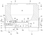
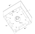
- the cooking utensil HC of this embodiment includes a rectangular parallelepiped utensil body 1.
- the utensil body 1 has an upper opening 11 at the top, an upper storage chamber 12 in which a rice cooker Kt can be stored through the opening 11, and a lower storage chamber 13 in which a burner Bn (described later) for heating the rice cooker Kt is arranged and communicates with the upper storage chamber 12.
- the upper surface of the appliance body 1 has an annular protruding wall 15 which is a part of the peripheral wall of the appliance body 1 surrounding the upper storage chamber 12 and defines the opening 11.
- the flange Kf which protrudes radially from the outer circumferential surface of the rice cooker Kt is seated on the upper surface of the protruding wall 15, and the rice cooker Kt is supported in a state where the part of the rice cooker Kt located below the flange Kf is stored in the upper storage chamber 12.
- a plurality of exhaust ports 16 are formed in the protruding wall 15 at intervals in the circumferential direction, and hydrogen combustion gas generated by the combustion of hydrogen gas is exhausted.
- a lid kd is placed on the upper opening of the rice cooker Kt during cooking.
- the partition plate portion 33 has an inner annular plate portion 33a which is screwed to the upper surface of the inner cylindrical portion 22 with the inner peripheral edge of the main body portion 31 sandwiched between it and an annular inner packing 34a placed on the upper surface of the inner cylindrical portion 22, an outer annular plate portion 33b which is screwed to the upper surface of the outer cylindrical portion 23 with the outer peripheral edge of the main body portion 31 sandwiched between it and an annular outer packing 34b placed on the upper surface of the outer cylindrical portion 23, and a beam plate portion 33c which radially bridges the inner annular plate portion 33a and the outer annular plate portion 33b.
- the beam plate portions 33c are arranged at 90 degree intervals in the circumferential direction, and the four openings defined by the inner annular plate portion 33a, the outer annular plate portion 33b and the beam plate portion 33c each constitute a combustion region 32 of the combustion plate 3.
- the flame color reaction agent there is no particular restriction on the flame color reaction agent as long as it does not cause hygienic problems and expresses chemiluminescence in the visible light region, and for example, compounds such as sodium chloride (yellow), sodium carbonate (yellow), and potassium chloride (reddish purple) can be used.
- compounds such as sodium chloride (yellow), sodium carbonate (yellow), and potassium chloride (reddish purple) can be used.
- the hydrogen flame reacts with the flame color reaction agent to cause a flame color reaction, making it possible to confirm the hydrogen flame.
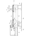
- a plurality of introduction passages 4 for introducing secondary air toward the hydrogen gas ejected from the combustion plate 3 through the flame hole 31a are provided at intervals in the circumferential direction in a plan view.
- four introduction passages 4 extending in the radial direction are provided corresponding to each combustion region 32.
- the introduction passages 4 have an intake port 41 opening on the outer surface 131 of the peripheral wall portion 13b and an exhaust port 42 opening on the inner surface 132 of the peripheral wall portion 13b. As shown in FIG.
- the inner surface region of the peripheral wall portion 13b containing the line Vl is defined as an exhaust port forming region 42a, and at least one exhaust port 42 is formed in the exhaust port forming region 42a.
- a pair of guide rails 5, 5 extending vertically are provided on the outer surface of the appliance body 1, positioned on both sides of the intake port 41 (see FIG. 1).
- a plate-shaped opening/closing door 6 that increases/decreases the opening area of the intake port 41 is engaged with the guide rails 5, 5 so as to be slidable vertically, and the opening/closing door 6 can be positioned and held by a locking device 7.
- the opening/closing door 6 constitutes an adjustment means that increases/decreases the opening area of the intake port 41 to adjust the amount of secondary air introduced into the lower storage chamber 13.
- a control box Cb is provided that incorporates a control board (not shown) that receives power from a battery, for example, and controls the operation of the burner Bn.
- a mounting plate 28 is provided on the bulging portion 23a of the outer cylinder 23, and a pair of rod-shaped electrodes 8a, 8b are attached to the mounting plate 28.
- a high voltage is applied between the pair of rod-shaped electrodes 8a, 8b from an igniter (not shown) controlled by the control board, and the hydrogen gas is ignited by the pyrotechnic discharge generated at that time, and the hydrogen gas is diffused and burned.
- the bottom surface of the rice cooker Kt is heated by the hydrogen flames generated in each combustion region 32, and the rice cooker Kt is heated by the hydrogen combustion gas generated by the combustion of the hydrogen gas while being exhausted to the exhaust port 16 along the outer peripheral wall of the rice cooker Kt.
- the exhaust port 16 is formed to straddle the combustion regions 32 adjacent to each other in a plan view so that the hydrogen combustion gas flows evenly around the rice cooker Kt.
- the amount of hydrogen gas ejected from the combustion area 32 (hereinafter referred to as the "combustion area 32b") of the combustion plate 3 away from the connecting pipe 25 is reduced compared to the amount of hydrogen gas ejected from the combustion area 32 (hereinafter referred to as the "combustion area 32a") close to the connection point of the connecting pipe 25. Therefore, in the introduction passage 4 corresponding to the combustion area 32b, the position of the opening door 6 relative to the intake port 41 is appropriately adjusted to increase the opening area of the intake port 41.
- the amount of secondary air introduced toward the hydrogen gas ejected from the combustion area 32b increases, so that the hydrogen flame can be extended to stand above the secondary air.
- the position of the opening door 6 relative to the intake port 41 is appropriately adjusted to decrease the opening area of the intake port 41.
- the amount of secondary air introduced toward the hydrogen gas decreases, so that the hydrogen flame can be tilted toward the discharge port 42 side.
- the height of the hydrogen flame from the combustion plate 3 can be made uniform in each combustion region 32 .
- the amount of secondary air can be adjusted for each combustion area 32 to make the height of the hydrogen flame in each combustion area 32 uniform, so that the bottom of the rice cooker Kt can be heated evenly by the burner Bn. Moreover, since the position of the opening and closing door 6 relative to the intake port 41 can be appropriately adjusted, even if the amount of hydrogen gas ejected from each combustion area 32 of the combustion plate 3 changes depending on the variation in manufacturing the cooking appliance HC or the situation when the cooking appliance HC is installed and used, the amount of secondary air can be further adjusted to match this change, which is advantageous.
- the present invention is not limited to this.
- four introduction passages 4 are provided corresponding to each combustion region 32 divided into four in the circumferential direction, but the number of divided combustion regions 32 and the number of introduction passages 4 can be set arbitrarily.
- the air intake 41 is provided in the peripheral wall portion 13b, but the present invention is not limited to this.
- the bottom surface of the bottom wall portion 13a of the appliance body 1, i.e., the bottom surface of the appliance body 1, is provided with legs Lp located at the four corners and protruding downward.
- a plurality of air intakes 41 of the introduction passage 4 are provided on the bottom surface of the appliance body 1.
- the rice cooker Kt as a cooking vessel is supported by seating its flange portion Kf on the upper surface of the protruding wall portion 15, but the shape is not important as long as it can support a cooking vessel stored in the upper storage chamber 12 through the opening 11.
- a mesh-like placement stand or trivet may be installed in the upper storage chamber 12 to support a cooking vessel.
- the combustion plate 3 of the burner Bn is described as having a ring-shaped main body portion 31 with a large number of flame holes 31a, but this is not limited to this.
- the combustion plate 3 can be made of a sintered sheet formed by sintering a laminate of metal fibers or metal beads.
- the appliance main body 1 is described as having a rectangular parallelepiped shape, but this is not limited to this, and for example, the appliance main body 1 may be cylindrical.
- the opening and closing door 6 may be shaped to fit the outer surface of the appliance main body 1.
- HC...heating cooking appliance Kt...kettle (cooking container), 1...apparatus body, 11...opening, 12...upper storage chamber, 13...lower storage chamber, 13a...bottom wall portion (outer wall portion of the appliance body surrounding the lower storage chamber), 13b...circumferential wall portion (outer wall portion of the appliance body surrounding the lower storage chamber), 16...exhaust port, Bn...burner, 2...burner body, 3...combustion plate, 32...combustion area, 4...introduction passage, Lp...legs, 41...intake port, 42...exhaust port, 42a...exhaust port forming area, 6...opening/closing door (adjustment means).
Landscapes
- Engineering & Computer Science (AREA)
- Chemical & Material Sciences (AREA)
- Combustion & Propulsion (AREA)
- Mechanical Engineering (AREA)
- General Engineering & Computer Science (AREA)
- Food Science & Technology (AREA)
- Gas Burners (AREA)
- Cookers (AREA)
Abstract
Priority Applications (2)
| Application Number | Priority Date | Filing Date | Title |
|---|---|---|---|
| KR1020257023062A KR20250117437A (ko) | 2023-06-30 | 2024-01-23 | 가열 조리 기구 |
| CN202480005428.7A CN121399416A (zh) | 2023-06-30 | 2024-01-23 | 加热烹调器具 |
Applications Claiming Priority (2)
| Application Number | Priority Date | Filing Date | Title |
|---|---|---|---|
| JP2023108150A JP2025007023A (ja) | 2023-06-30 | 2023-06-30 | 加熱調理器具 |
| JP2023-108150 | 2023-06-30 |
Publications (1)
| Publication Number | Publication Date |
|---|---|
| WO2025004419A1 true WO2025004419A1 (fr) | 2025-01-02 |
Family
ID=93938316
Family Applications (1)
| Application Number | Title | Priority Date | Filing Date |
|---|---|---|---|
| PCT/JP2024/001840 Ceased WO2025004419A1 (fr) | 2023-06-30 | 2024-01-23 | Cuiseur chauffant |
Country Status (4)
| Country | Link |
|---|---|
| JP (1) | JP2025007023A (fr) |
| KR (1) | KR20250117437A (fr) |
| CN (1) | CN121399416A (fr) |
| WO (1) | WO2025004419A1 (fr) |
Citations (7)
| Publication number | Priority date | Publication date | Assignee | Title |
|---|---|---|---|---|
| JPS50139152U (fr) * | 1974-05-07 | 1975-11-15 | ||
| JPS5910723U (ja) * | 1982-07-13 | 1984-01-23 | パロマ工業株式会社 | 保温ジヤ−付きガス炊飯器 |
| JP2005185438A (ja) * | 2003-12-25 | 2005-07-14 | Seiko Kikai Kk | 炊飯装置 |
| JP2006145104A (ja) * | 2004-11-19 | 2006-06-08 | Seiko Kikai Kk | 火炎燃焼バーナとそれを用いる加熱調理装置 |
| JP2007192485A (ja) * | 2006-01-20 | 2007-08-02 | Takuma Co Ltd | ガスバーナ |
| JP2010266160A (ja) * | 2009-05-18 | 2010-11-25 | Dainichi Co Ltd | 燃焼装置 |
| JP2018089101A (ja) * | 2016-12-02 | 2018-06-14 | 株式会社アイホー | 加熱調理装置 |
Family Cites Families (1)
| Publication number | Priority date | Publication date | Assignee | Title |
|---|---|---|---|---|
| JPH11337071A (ja) | 1998-05-28 | 1999-12-10 | Kazuo Kito | 炊飯かまど |
-
2023
- 2023-06-30 JP JP2023108150A patent/JP2025007023A/ja active Pending
-
2024
- 2024-01-23 KR KR1020257023062A patent/KR20250117437A/ko active Pending
- 2024-01-23 WO PCT/JP2024/001840 patent/WO2025004419A1/fr not_active Ceased
- 2024-01-23 CN CN202480005428.7A patent/CN121399416A/zh active Pending
Patent Citations (7)
| Publication number | Priority date | Publication date | Assignee | Title |
|---|---|---|---|---|
| JPS50139152U (fr) * | 1974-05-07 | 1975-11-15 | ||
| JPS5910723U (ja) * | 1982-07-13 | 1984-01-23 | パロマ工業株式会社 | 保温ジヤ−付きガス炊飯器 |
| JP2005185438A (ja) * | 2003-12-25 | 2005-07-14 | Seiko Kikai Kk | 炊飯装置 |
| JP2006145104A (ja) * | 2004-11-19 | 2006-06-08 | Seiko Kikai Kk | 火炎燃焼バーナとそれを用いる加熱調理装置 |
| JP2007192485A (ja) * | 2006-01-20 | 2007-08-02 | Takuma Co Ltd | ガスバーナ |
| JP2010266160A (ja) * | 2009-05-18 | 2010-11-25 | Dainichi Co Ltd | 燃焼装置 |
| JP2018089101A (ja) * | 2016-12-02 | 2018-06-14 | 株式会社アイホー | 加熱調理装置 |
Also Published As
| Publication number | Publication date |
|---|---|
| CN121399416A (zh) | 2026-01-23 |
| JP2025007023A (ja) | 2025-01-17 |
| KR20250117437A (ko) | 2025-08-04 |
Similar Documents
| Publication | Publication Date | Title |
|---|---|---|
| CN101509672B (zh) | 燃气灶 | |
| KR20170043756A (ko) | 가스버너장치 및 이를 포함하는 조리기기 | |
| WO2008033238A2 (fr) | Brûleur à gaz amélioré | |
| US9080774B2 (en) | Cooker | |
| US9702564B2 (en) | Cooker | |
| KR20140137721A (ko) | 이중 버너 형태의 가스 버너 | |
| US20200182474A1 (en) | Gas burner | |
| WO2025004419A1 (fr) | Cuiseur chauffant | |
| US3299941A (en) | Burner | |
| GB2160642A (en) | Gas fire | |
| KR101598625B1 (ko) | 탑버너 및 이를 포함하는 조리기기 | |
| JP2025007024A (ja) | 加熱調理器具 | |
| KR101596497B1 (ko) | 탑버너 및 이를 포함하는 조리기기 | |
| KR20090064606A (ko) | 버너 및 이를 포함하는 조리기기 | |
| TWI850556B (zh) | 加熱調理裝置 | |
| CN116182158A (zh) | 一种三环火燃烧器 | |
| KR20100069015A (ko) | 탑버너 및 이를 포함하는 조리기기 | |
| JP2002181310A (ja) | コンロバーナ | |
| JP2005207668A (ja) | ガスコンロ | |
| JP2025123114A (ja) | ガスバーナ並びに加熱調理器 | |
| CN218583151U (zh) | 一种燃烧器 | |
| KR20100069014A (ko) | 탑버너 및 이를 포함하는 조리기기 | |
| US20250321001A1 (en) | Stacked burner with channel for improved ignition | |
| JP5975765B2 (ja) | 加熱調理装置 | |
| KR100763571B1 (ko) | 적열식 휴대용 가스렌지 |
Legal Events
| Date | Code | Title | Description |
|---|---|---|---|
| 121 | Ep: the epo has been informed by wipo that ep was designated in this application |
Ref document number: 24831300 Country of ref document: EP Kind code of ref document: A1 |
|
| ENP | Entry into the national phase |
Ref document number: 1020257023062 Country of ref document: KR Free format text: ST27 STATUS EVENT CODE: A-0-1-A10-A15-NAP-PA0105 (AS PROVIDED BY THE NATIONAL OFFICE) |
|
| WWE | Wipo information: entry into national phase |
Ref document number: 1020257023062 Country of ref document: KR |
|
| WWP | Wipo information: published in national office |
Ref document number: 1020257023062 Country of ref document: KR |
|
| NENP | Non-entry into the national phase |
Ref country code: DE |