WO2025004494A1 - Armoire - Google Patents
Armoire Download PDFInfo
- Publication number
- WO2025004494A1 WO2025004494A1 PCT/JP2024/014401 JP2024014401W WO2025004494A1 WO 2025004494 A1 WO2025004494 A1 WO 2025004494A1 JP 2024014401 W JP2024014401 W JP 2024014401W WO 2025004494 A1 WO2025004494 A1 WO 2025004494A1
- Authority
- WO
- WIPO (PCT)
- Prior art keywords
- recess
- cabinet
- reinforcing member
- abutment
- cabinet body
- Prior art date
- Legal status (The legal status is an assumption and is not a legal conclusion. Google has not performed a legal analysis and makes no representation as to the accuracy of the status listed.)
- Ceased
Links
Images


Classifications
-
- A—HUMAN NECESSITIES
- A47—FURNITURE; DOMESTIC ARTICLES OR APPLIANCES; COFFEE MILLS; SPICE MILLS; SUCTION CLEANERS IN GENERAL
- A47B—TABLES; DESKS; OFFICE FURNITURE; CABINETS; DRAWERS; GENERAL DETAILS OF FURNITURE
- A47B67/00—Chests; Dressing-tables; Medicine cabinets or the like; Cabinets characterised by the arrangement of drawers
- A47B67/02—Cabinets for shaving tackle, medicines, or the like
-
- A—HUMAN NECESSITIES
- A47—FURNITURE; DOMESTIC ARTICLES OR APPLIANCES; COFFEE MILLS; SPICE MILLS; SUCTION CLEANERS IN GENERAL
- A47K—SANITARY EQUIPMENT; ACCESSORIES THEREFOR, e.g. TOILET ACCESSORIES
- A47K1/00—Wash-stands; Appurtenances therefor
- A47K1/02—Portable toilet tables; Wash cabinets or stands
Definitions
- This disclosure relates to a cabinet, and more specifically, to a cabinet with a storage recess on the front.
- the reinforcing back plate is attached to the inner periphery of the outer frame of the cabinet body. Therefore, a large component that covers the entire opening on the back side of the cabinet body is required as the reinforcing back plate.
- the problem that this disclosure aims to solve is to provide a cabinet that is effectively reinforced without requiring large components.
- a cabinet comprises a cabinet body having a front and a back, and a reinforcing member attached to the back of the cabinet body.
- the front of the cabinet body includes a storage recess used for storage.
- the back of the cabinet body includes a back protrusion that constitutes the back side of the storage recess, and a back recess formed around the back protrusion.
- the reinforcing member is a member that is fitted into the back recess, and has an abutment surface that conforms to the back recess.
- FIG. 1 is a front view of a cabinet body provided in a cabinet according to a first embodiment.
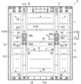
- FIG. 2 is a rear view of the cabinet body with the reinforcing member attached thereto.
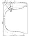
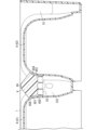
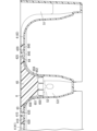
- FIG. 3 is a cross-sectional view taken along line AA of FIG.
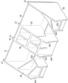
- FIG. 4 is a perspective view of a main part of the cabinet body.
- FIG. 5 is a rear view of the reinforcing member.
- FIG. 6 is a perspective view of the reinforcing member.
- FIG. 7 is a rear view of the cabinet body according to the second embodiment with the reinforcing members attached thereto.
- FIG. 8 is a cross-sectional view taken along line BB in FIG.
- FIG. 9 is a rear view of the reinforcing member.
- FIG. 1 is a front view of a cabinet body provided in a cabinet according to a first embodiment.
- FIG. 2 is a rear view of the cabinet body with the reinforcing member attached thereto.
- FIG. 3 is
- FIG. 10 is a perspective view of the reinforcing member.
- FIG. 11 is a rear view of the cabinet body according to the third embodiment with the reinforcing members attached thereto.
- FIG. 12 is a cross-sectional view taken along line CC of FIG.
- FIG. 13 is a rear view of the cabinet body according to the fourth embodiment with the reinforcing members attached thereto.
- FIG. 14 is a cross-sectional view taken along line DD in FIG.
- FIG. 15 is a rear view of the cabinet body according to the fifth embodiment with the reinforcing members attached thereto.
- FIG. 16 is a cross-sectional view taken along line E--E of FIG.
- FIG. 17 is a perspective view of the reinforcing member.
- FIG. 18 is a cross-sectional view of a main part of a cabinet body according to the sixth embodiment with a reinforcing member attached thereto.
- a cabinet 9 according to a first embodiment will be described with reference to Fig. 1 to Fig. 6.
- the cabinet 9 according to the first embodiment is, for example, a washstand cabinet to be installed on a washstand. Each direction used in the following description is based on a state in which the cabinet 9 is installed.
- the cabinet 9 of the first embodiment includes a cabinet body 1 constituting the main body of the cabinet 9, and a reinforcing member 6 attached to the cabinet body 1.
- the cabinet body 1 has a front surface 10 and a back surface 15.
- a mirror cabinet is formed by attaching appropriate components to the front surface 10 of the cabinet body 1. Suitable components include, for example, a mirrored door (not shown) that is rotatably attached to the front surface 10 of the cabinet body 1, and a shelf that is attached to the front surface 10 of the cabinet body 1.
- a cabinet body 1 constituting the main body of the cabinet 9 is formed using a thin resin plate.
- the cabinet body 1 is given an uneven structure including a plurality of storage recesses 2 used to store items and an outer frame 3 constituting the outer periphery of the cabinet body 1.
- a plurality of storage recesses 2 are provided on a front surface 10 of a cabinet main body 1.
- the plurality of storage recesses 2 are three storage recesses 2 arranged side by side in the left-right direction.
- the three storage recesses 2 are positioned at a distance from each other in the left-right direction.
- the three storage recesses 2 are independent from each other.
- the three storage recesses 2 are composed of a first storage recess 21 located in the center in the left-right direction, and a second storage recess 22 and a third storage recess 23 located on either side of the first storage recess 21 in the left-right direction.
- the vertical dimensions (in other words, the height dimensions) of the first storage recess 21, the second storage recess 22, and the third storage recess 23 are the same.
- the left-right dimension (in other words, the width dimension) of the first storage recess 21 is greater than the left-right dimension of the second storage recess 22, and is also greater than the left-right dimension of the third storage recess 23.
- the left-right dimensions of the second storage recess 22 and the third storage recess 23 are the same.
- the dimensions in the front-to-rear direction (in other words, the depth dimensions) of the first storage recess 21, the second storage recess 22, and the third storage recess 23 are the same.
- the first storage recess 21, the second storage recess 22, and the third storage recess 23 each have a rectangular shape that is long vertically when viewed from the front.
- Each of the first storage recess 21, the second storage recess 22, and the third storage recess 23 has a plurality of grooves 25 for attaching shelves (not shown). Each groove 25 extends horizontally.
- each groove 25 is provided over the entire area in the horizontal direction.
- the outer frame 3 constituting the outer periphery of the cabinet body 1 protrudes rearward from the outer periphery of the rear surface 15 of the cabinet body 1.
- the outer frame 3 has a rectangular shape in rear view.
- the outer frame 3 includes a first frame 31, a second frame 32, a third frame 33, and a fourth frame 34.
- the first frame 31 and the second frame 32 are positioned apart from each other in the left-right direction, and each has a linear outer shape extending in the up-down direction.
- the first frame 31 and the second frame 32 form both left and right end edges of the cabinet body 1.
- the third frame 33 and the fourth frame 34 are positioned apart from each other in the up-down direction, and each has a linear outer shape extending in the left-right direction.
- the third frame 33 and the fourth frame 34 form both upper and lower end edges of the cabinet body 1.
- the first frame 31, the second frame 32, the third frame 33, and the fourth frame 34 are continuous throughout the entire circumference of the cabinet body 1.
- the rectangular outer frame 3 is positioned to surround a number of rear convex portions 4 and rear concave portions 5 (described below) included in the rear surface 15 of the cabinet body 1.
- a plurality of rear protrusions 4 are formed on the rear surface 15 of the cabinet body 1.
- the plurality of rear protrusions 4 form the rear sides of the plurality of storage recesses 2 on the rear surface 15 of the cabinet body 1.
- these multiple rear protrusions 4 are recesses formed on the rear surface 15 of the cabinet body 1 when a thin resin plate is vacuum-molded to form multiple storage recesses 2 on the front surface 10 of the cabinet body 1.
- the multiple rear protrusions 4 on the front surface 10 of the cabinet body 1 and the multiple storage recesses 2 on the rear surface 15 of the cabinet body 1 are in a one-to-one relationship.
- the multiple rear protrusions 4 are three rear protrusions 4 positioned at a distance from each other in the left-right direction.
- the three rear protrusions 4 are independent of each other.
- the three rear protrusions 4 are composed of a first rear protrusion 41 located in the center in the left-right direction, and a second rear protrusion 42 and a third rear protrusion 43 located on either side of the first rear protrusion 41 in the left-right direction.
- the first rear convex portion 41 is on the opposite side to the first storage recess 21 molded in the front face 10 of the cabinet body 1.
- the first rear convex portion 41 is a convex portion molded in the rear face 15 of the cabinet body 1 as a result of the first storage recess 21 being vacuum molded in the front face 10 of the cabinet body 1.
- the second rear convex portion 42 is on the opposite side to the second storage recess 22 molded in the front face 10 of the cabinet body 1.
- the second rear convex portion 42 is a convex portion molded in the rear face 15 of the cabinet body 1 as a result of the second storage recess 22 being vacuum molded in the front face 10 of the cabinet body 1.
- the third rear convex portion 43 is on the opposite side to the third storage recess 23 molded in the front face 10 of the cabinet body 1.
- the third rear convex portion 43 is a convex portion molded in the rear face 15 of the cabinet body 1 as a result of the third storage recess 23 being vacuum molded in the front face 10 of the cabinet body 1.
- first rear convex portion 41, second rear convex portion 42, and third rear convex portion 43 have the same vertical dimensions (in other words, height dimensions).
- the left-right dimension of the first rear convex portion 41 is greater than the left-right dimension of the second rear convex portion 42, and is also greater than the left-right dimension of the third rear convex portion 43.
- the left-right dimensions of the second rear convex portion 42 and the third rear convex portion 43 are identical to each other.
- the front-rear dimensions (in other words, protruding dimensions toward the back) of the first rear convex portion 41, second rear convex portion 42, and third rear convex portion 43 are identical to each other.
- the first rear protrusion 41, the second rear protrusion 42, and the third rear protrusion 43 each have a rectangular shape that is long in the vertical direction when viewed from the rear.
- Each of the first rear protrusion 41, the second rear protrusion 42, and the third rear protrusion 43 is provided with a plurality of ribs 45.
- Each rib 45 is a linear rib that extends in the horizontal direction.
- the multiple ribs 45 are protruding parts that form the back side of the multiple grooves 25 provided on the front face 10 of the cabinet body 1.
- these multiple ribs 45 are convex parts formed on the back face 15 of the cabinet body 1 when a thin resin plate is vacuum-formed to form the multiple grooves 25 on the front face 10 of the cabinet body 1.
- the multiple grooves 25 on the front face 10 of the cabinet body 1 and the multiple ribs 45 on the back face 15 of the cabinet body 1 are in a one-to-one relationship, back-to-back.
- each rib 45 is arranged in parallel with a distance in the up-down direction.
- each rib 45 is provided across the entire area in the left-right direction.
- a rear recess 5 is further formed on the rear surface 15 of the cabinet body 1.
- the rear recess 5 is formed around each rear protrusion 4 (i.e., each of the first rear protrusion 41, the second rear protrusion 42, and the third rear protrusion 43).
- the rear recess 5 is a portion that is recessed relatively with respect to each rear protrusion 4.
- the rear recess 5 of the cabinet body 1 includes an outer recess 51 and an inner recess 53 located inside the outer recess 51.
- the outer recess 51 is formed between the outer frame 3 of the cabinet main body 1 and the multiple rear protrusions 4 of the cabinet main body 1.
- the outer recess 51 is a portion that is relatively recessed with respect to the outer frame 3 and the multiple rear protrusions 4.
- the outer recess 51 includes a first outer recess 511, a second outer recess 512, a third outer recess 513, and a fourth outer recess 514.
- the first outer recess 511 and the second outer recess 512 are located apart from each other in the left-right direction, and each is a linear recess extending in the up-down direction.
- the first outer recess 511 and the second outer recess 512 are parallel grooves, and each is open to the rear.
- the left-right dimensions (in other words, width dimensions) of the first outer recess 511 and the second outer recess 512 are the same.
- the up-down dimensions of the first outer recess 511 and the second outer recess 512 are the same.
- the third outer recess 513 and the fourth outer recess 514 are located apart from each other in the up-down direction, and each is a linear recess extending in the left-right direction.
- the third outer recess 513 and the fourth outer recess 514 are parallel grooves, and each is open to the rear.
- the up-down dimensions (in other words, width dimensions) of the third outer recess 513 and the fourth outer recess 514 are the same.
- the left-right dimensions of the third outer recess 513 and the fourth outer recess 514 are the same.
- the first outer recess 511, the second outer recess 512, the third outer recess 513, and the fourth outer recess 514 are continuous together to form a rectangular frame as a whole.
- the inner recess 53 is a relative recess formed between two of the three rear protrusions 4 (i.e., the first rear protrusion 41, the second rear protrusion 42, and the third rear protrusion 43) that are positioned next to each other in the left-right direction.
- the inner recess 53 includes a first inner recess 531 and a second inner recess 532.
- the first inner recess 531 and the second inner recess 532 are positioned apart from each other in the left-right direction, sandwiching the first rear protrusion 41.
- the first inner recess 531 is a linear recess formed between the first rear protrusion 41 and the second rear protrusion 42, which are positioned next to each other in the left-right direction.
- the first inner recess 531 is configured as a linear groove extending in the up-down direction.
- the second inner recess 532 is a linear recess formed between the first rear protrusion 41 and the third rear protrusion 43, which are positioned next to each other in the left-right direction.
- the second inner recess 532 is configured as a linear groove extending in the up-down direction.
- the first inner recess 531 and the second inner recess 532 are parallel grooves, each of which is open to the rear.
- the left-right dimensions (in other words, width dimensions) of the first inner recess 531 and the second inner recess 532 are identical.
- the up-down dimensions of the first outer recess 511 and the second outer recess 512 are identical.
- the outer recess 51 and the inner recess 53 constituting the rear recess 5 are formed as one continuous unit. Specifically, the third outer recess 513 and the fourth outer recess 514 included in the outer recess 51, and the first inner recess 531 and the second inner recess 532 included in the inner recess 53 are formed as one continuous unit.
- the upper end of the first inner recess 531 extending in the vertical direction is connected to a portion of the left-right direction of the third outer recess 513 located above, and the lower end of the first inner recess 531 is connected to a portion of the left-right direction of the fourth outer recess 514 located below.
- the upper end of the second inner recess 532 extending in the vertical direction is connected to a portion of the left-right direction of the third outer recess 513 located above, and the lower end of the second inner recess 532 is connected to a portion of the left-right direction of the fourth outer recess 534 located below.
- the reinforcing member 6 is attached to the back surface 15 of the cabinet body 1 in order to suppress deformation of the cabinet body 1, which is molded from a thin resin plate.
- the back surface 15 of the cabinet body 1 and the reinforcing member 6 attached thereto are covered and hidden by the outer frame 3.
- the reinforcing member 6 is fitted into a part of the rear recess 5 of the cabinet body 1 from the rear side of the cabinet body 1.
- the part of the rear recess 5 into which the reinforcing member 6 is fitted is part of the outer recess 51 included in the rear recess 5.
- the reinforcing member 6 is fitted into each of the first outer recess 511 and the second outer recess 512 which form part of the outer recess 51.
- the reinforcing member 6 is a resin molded product that includes a main body portion 65 that constitutes the main body of the reinforcing member 6, and a contact portion 61 that is integral with the main body portion 65.
- the main body 65 of the reinforcing member 6 has a rectangular shape that is long in the vertical direction when viewed from the rear, and has a pair of recesses 655 that are open toward the same side in the horizontal direction (see FIG. 5, etc.).
- the pair of recesses 655 are positioned at a distance in the vertical direction and have the same dimensions and shape.
- Each recess 655 is open toward one side in the horizontal direction, and is also open in the front-rear direction.
- the one side in the horizontal direction where each recess 655 is open is referred to as the first side in the horizontal direction, and the opposite side is referred to as the second side in the horizontal direction.
- the end face of the main body 65 on the first side in the left-right direction forms an abutment surface 650 for abutting against the inner side of the rear recess 5.
- the abutment surface 650 abuts against the inner side of the outer recess 51 that constitutes part of the rear recess 5, and more specifically, abuts against the inner side of the first outer recess 511 or the second outer recess 512.
- the abutment surface 650 of the main body 65 includes an end face of a rib 653 that protrudes to a first side in the left-right direction.
- a plurality of the ribs 653 are provided at intervals in the up-down direction.
- the plurality of ribs 653 are four ribs 653 that are positioned parallel to each other at intervals in the up-down direction.
- Each rib 653 has a shape that extends linearly in the front-rear direction.
- the four ribs 653 are composed of two ribs 653 located at both ends of the main body 65 in the up-down direction, and two other ribs 653 located between a pair of recesses 655 in the up-down direction.
- the end faces of the four ribs 653 each have a concave curved shape.
- the end faces of the four ribs 653 have the same shape.
- the abutment surface 650 of the main body 65 composed of the end faces of the four ribs 653 has a concave curved shape that follows the convex inner surface of the outer recess 51.
- the abutment surface 650 of the main body 65 of the reinforcing member 6 abuts against the convex curved portion of the inner surface of the first outer recess 511.
- the abutment surface 650 of the main body 65 has a shape that follows the convex curved portion of the inner surface of the first outer recess 511.
- each rib 653 included in the main body 65 each abut against the convex side surface of the second rear convex portion 42.
- the end face of each rib 653 has a shape that follows the convex surface of the second rear convex portion 42.
- the convex surface of the second rear convex portion 42 is a curved surface that has an arc-shaped horizontal cross section.
- the reinforcing member 6 is fitted between a pair of upper and lower ribs 516 provided in the first outer recess 511.
- the pair of ribs 516 are ribs that protrude from the inner surface of the first frame 31 of the outer frame 3 (see Figure 4).
- Each of the pair of ribs 516 is a rib that extends linearly in the front-to-rear direction and is parallel to each other.
- Each rib 516 is provided so that it protrudes more from the outer frame 3 the further back it is.
- the reinforcing member 6 When the reinforcing member 6 is fitted into the first outer recess 511, the reinforcing member 6 is pressed between the pair of ribs 516. In addition, the main body 65 of the reinforcing member 6 is pressed and fixed between the first frame 31 and the second rear protrusion 42 (i.e., the first outer recess 511).
- the abutment surface 650 of the main body 65 of the reinforcing member 6 abuts against the convex portion of the inner surface of the second outer recess 512.
- the abutment surface 650 of the main body 65 has a shape that conforms to the convex portion of the inner surface of the second outer recess 512.
- each rib 653 included in the main body 65 each abut against the convex side surface of the third rear convex portion 43.
- the end face of each rib 653 has a shape that follows the convex surface of the third rear convex portion 43.
- the convex surface of the third rear convex portion 43 is a curved surface that has an arc-shaped horizontal cross section, similar to the second rear convex portion 42.
- the reinforcing member 6 is fitted between a pair of upper and lower ribs 517 provided in the second outer recess 512.
- the pair of ribs 517 are ribs that protrude from the inner surface of the second frame 32 of the outer frame 3.
- Each of the pair of ribs 517 is a rib that extends linearly in the front-rear direction and is parallel to each other.
- the reinforcing member 6 When the reinforcing member 6 is fitted into the second outer recess 512, the reinforcing member 6 is pressed between the pair of ribs 517. In addition, the main body 65 of the reinforcing member 6 is pressed and fixed between the second frame 32 and the third rear protrusion 43 (i.e., the second outer recess 512).
- the abutment portion 61 of the reinforcing member 6 is a portion that abuts against the inner surface of the outer frame 3.
- a plurality of ribs 67 protruding from the main body portion 65 to the second side in the left-right direction constitute the abutment portion 61 (see FIGS. 5 and 6 ).
- the multiple ribs 67 are four ribs 67 that are positioned parallel to each other and spaced apart in the vertical direction. Each rib 67 has a linear shape that extends in the front-to-rear direction.
- the flat surfaces at the tips of the four ribs 67 form abutment surfaces 610 that abut against the inner surface of the outer frame 3. More specifically, the abutment surfaces 610 abut against the inner surface of the first frame 31 or the second frame 32.
- the four ribs 67 that make up the abutment portion 61 correspond one-to-one with the four ribs 653 provided on the main body portion 65.
- the main body portion 65 is provided with four flat connecting portions 68 that connect the one-to-one corresponding ribs 653, 67 to each other.
- the four connecting portions 68 are positioned parallel to one another and spaced apart in the vertical direction.
- the four ribs 67 are arranged so that they protrude more from the main body 65 toward the rear.
- the surfaces of the tips of the four ribs 67 i.e., the abutment surfaces 610) are slightly inclined so as to push the outer frame 3 outward when the reinforcing member 6 is inserted into the outer recess 51.
- the abutment surface 610 of the abutment portion 61 of the reinforcing member 6 abuts against the flat inner surface of the first frame 31.
- the tip surfaces of the four ribs 67 slide against the inner surface of the first frame 31, pushing the first frame 31 slightly outward, and acting to correct the shape of the first frame 31 outward.
- the abutment surface 610 of the abutment portion 61 of the reinforcing member 6 abuts against the flat inner surface of the second frame 32.
- the tip surfaces of the four ribs 67 slide against the inner surface of the second frame 32, pushing the second frame 32 slightly outward, thereby correcting the shape of the second frame 32.
- the cabinet body 1 is effectively reinforced and the shape of the cabinet body 1 is corrected by inserting the small reinforcing member 6 into the cabinet body 1 molded using a thin resin plate. Therefore, a cabinet 9 that is effectively reinforced and has a corrected shape can be obtained without requiring a large member as in the conventional technology.
- the reinforcing member 6 of the first embodiment can be attached to a cabinet body 1 of a different size than the cabinet body 1 of the first embodiment, for example. By sharing the reinforcing member 6 with cabinet bodies 1 of different sizes, costs can be reduced.
- Second embodiment A cabinet 9 according to a second embodiment will be described with reference to Fig. 7 to Fig. 10. Note that the same components as those in the above-described embodiment are denoted by the same reference numerals, and detailed description thereof will be omitted.
- a reinforcing member 6 of a different shape is inserted into the cabinet body 1 that has a common configuration with the first embodiment.
- the reinforcing member 6 provided in the cabinet 9 of the second embodiment includes a main body portion 65, an abutment portion 61, and an abutment portion 62.
- the abutment portion 61 of the reinforcing member 6 is referred to as the first abutment portion 61
- the abutment portion 62 is referred to as the second abutment portion 62.
- the main body portion 65 is the portion of the reinforcing member 6 that abuts against the rear recess 5, and more specifically, the portion that abuts against the first outer recess 511 or the second outer recess 512 of the outer recess 51.
- the abutment portion 61 is the portion of the reinforcing member 6 that abuts against the inner surface of the outer frame 3.
- the second abutment portion 62 is a portion that abuts against the rear-facing surface 40 of the rear convex portion 4, and more specifically, is a portion that abuts against the rear-facing flat surface 420 of the second rear convex portion 42, or abuts against the rear-facing flat surface 430 of the third rear convex portion 43.
- the portion protruding from the main body 65 to the first side in the left-right direction constitutes the second abutment portion 62.
- the second abutment portion 62 is a protruding piece-like portion that extends linearly in the left-right direction, and has an abutment surface 620 shaped along the surface 40 of the rear protrusion 4.
- the second contact portion 62 is located on the opposite side of the main body portion 65 from the first contact portion 61.
- the second contact portion 62 protrudes from a portion of the main body portion 65 that is located between a pair of recesses 655 in the up-down direction to the first side in the left-right direction.
- the two ribs 653 located between the pair of recesses 655 in the vertical direction are continuous with the second abutment portion 62.
- the concave end faces of the two ribs 653 i.e., the concave abutment surface 650 of the main body portion 65
- the contact surface 620 of the second contact portion 62 is a flat surface that contacts the surface 40 of the rear convex portion 4, and more specifically, is a flat surface configured to contact the surface 420 of the second rear convex portion 42 or the surface 430 of the third rear convex portion 43.
- the second abutment portion 62 which has a rectangular flat plate-like outer shape, is provided with a locking portion 625.
- the locking portion 625 is configured to lock onto a part of the rear protrusion 4, and more specifically, is configured to lock onto a locking body 423 that constitutes a part of the second rear protrusion 42, or to lock onto a locking body 433 that constitutes a part of the third rear protrusion 43.
- the locking body 423 of the second rear protrusion 42 and the locking body 433 of the third rear protrusion 43 both have a cylindrical boss shape.
- the engaging portion 625 of the reinforcing member 6 includes a hole 626 that penetrates the second abutment portion 62 in the front-rear direction, and a number of ribs 627 that protrude from the inner peripheral surface of the hole 626.
- the multiple ribs 627 are positioned in a line in the circumferential direction of the hole 626.
- the multiple ribs 627 are positioned at equal intervals in the circumferential direction of the hole 626, and each protrudes toward the center of the hole 626.
- the abutment surface 650 of the main body 65 of the reinforcing member 6 i.e., the end faces of the four ribs 653 abuts against the convex curved portion of the first outer recess 511.
- the abutment surface 610 of the first abutment portion 61 of the reinforcing member 6 i.e., the protruding surfaces of the four ribs 67 that constitute the first abutment portion 61
- the abutment surface 620 of the second abutment portion 62 of the reinforcing member 6 abuts against the flat surface 420 facing the rear of the second rear convex portion 42.
- a boss-shaped locking body 423 protruding from the surface 420 of the second rear convex portion 42 is inserted into the locking portion 625 of the second abutment portion 62.
- the tips of multiple ribs 627 included in the locking portion 625 are pressed against the outer peripheral surface of the boss-shaped locking body 423.
- the locking body 423 of the second rear convex portion 42 is pressed into the locking portion 625 of the second abutment portion 62, and the reinforcing member 6 is fixed more firmly.
- being pressed in includes engaging with each other and stopping, i.e., being locked.
- the abutment surface 650 of the main body 65 of the reinforcing member 6 abuts against the convex curved portion of the second outer recess 512.
- the abutment surface 610 of the first abutment portion 61 of the reinforcing member 6 abuts against the inner surface of the second frame 32.
- the abutment surface 620 of the second abutment portion 62 of the reinforcing member 6 abuts against the flat surface 430 facing the rear of the third rear convex portion 43.
- a boss-shaped locking body 433 protruding from the surface 430 of the third rear convex portion 43 is inserted into the locking portion 625 of the second abutment portion 62.
- the tips of the multiple ribs 627 included in the locking portion 625 are pressed against the outer peripheral surface of the boss-shaped locking body 433.
- the locking body 433 of the second rear convex portion 42 is pressed into the locking portion 625 of the second abutment portion 62, and the reinforcing member 6 is fixed more firmly.
- the locking bodies 423, 433 of the rear convex portion 4 instead of the locking bodies 423, 433 of the rear convex portion 4 having a boss shape, it is also preferable that the locking portion 625 of the second abutment portion 62 has a boss shape.
- the locking bodies 423, 433 of the rear convex portion 4 include, for example, a hole and a number of ribs protruding from the inner peripheral surface of the hole. In other words, it is sufficient that one of the locking bodies 423, 433 of the rear convex portion 4 and the locking portion 625 of the second abutment portion 62 has a boss shape and the other has a rib that is press-fitted and fixed thereto.
- a reinforcing member 6 of a different shape is inserted into the cabinet body 1 that has a common configuration with the first embodiment.
- the part of the rear recess 5 into which the reinforcing member 6 is fitted is not a part of the outer recess 51 included in the rear recess 5, but a part of the inner recess 53 included in the rear recess 5.
- the reinforcing member 6 is fitted into a part of the first inner recess 531 included in the inner recess 53 and a part of the second inner recess 532 included in the inner recess 53.
- the main body portion 65 constituting the main body of the reinforcing member 6 has a rectangular shape that is long in the vertical direction when viewed from behind, and has a pair of recesses 656 that open toward one side in the horizontal direction, and a pair of recesses 657 that open toward the other side in the horizontal direction.
- the one side in the horizontal direction where each recess 656 is open is referred to as the first side in the horizontal direction
- the other side in the horizontal direction where each recess 657 is open is referred to as the second side in the horizontal direction.
- the pair of recesses 656 are positioned at a distance in the up-down direction. Each recess 656 is open toward a first side in the left-right direction, and is also open in the front-to-rear direction. Similarly, the pair of recesses 657 are positioned at a distance in the up-down direction. Each recess 657 is open toward a second side in the left-to-right direction, and is also open in the front-to-rear direction.
- an end face 651 on a first left-right side of the main body 65 and an end face 652 on a second left-right side of the main body 65 form an abutment surface 650.
- the end faces 651 and 652 of the main body 65 abut against the inner surface of the inner recess 53 included in the rear recess 5, and more specifically, abut against the inner surface of the first inner recess 531 or the second inner recess 532.
- the end face 651 of the main body 65 includes an end face of a rib 658 that protrudes to a first side in the left-right direction.
- a plurality of ribs 658 are provided at intervals in the up-down direction.
- the end face of each rib 658 has a concave curved shape.
- the end face 651 of the main body 65 formed by the end faces of these ribs 658 has a concave curved shape.
- the end face 652 of the main body 65 includes an end face of a rib 659 that protrudes to the second side in the left-right direction.
- a plurality of ribs 659 are provided at intervals in the up-down direction.
- the end face of each rib 659 has a concave curved shape.
- the end face 652 of the main body 65 formed by the end faces of these ribs 659 has a concave curved shape.
- the end faces 651 and 652 of the main body 65 of the reinforcing member 6 abut against the convex portion of the inner surface of the first inner recess 531.
- the end faces 651 and 652 of the main body 65 have a shape that follows the convex portion of the inner surface of the first outer recess 511.
- each rib 658 included in the main body 65 abut against the convex side surface of the first rear convex portion 41.
- the end faces of each rib 658 have a shape that follows the convex surface of the first rear convex portion 41.
- one of the multiple ribs 45 provided on the first rear convex portion 41 is inserted into one of the pair of recesses 656 of the reinforcing member 6.
- each rib 659 included in the main body 65 abut against the convex curved side of the second rear convex portion 42.
- the end faces of each rib 659 have a shape that conforms to the convex curved surface of the second rear convex portion 42.
- two ribs 45 positioned next to each other in the vertical direction are inserted one-to-one into a pair of recesses 657 of the reinforcing member 6.
- the main body 65 of the reinforcing member 6 is pressed and fixed between the first rear convex portion 41 and the second rear convex portion 42 (i.e., the first inner recess 531).
- the end faces 651 and 652 of the main body 65 of the reinforcing member 6 abut against the convex portion of the inner surface of the second inner recess 532.
- the end faces 651 and 652 of the main body 65 have a shape that follows the convex portion of the inner surface of the second outer recess 512.
- each rib 658 included in the main body 65 abut against the convex side surface of the first rear convex portion 41.
- the end faces of each rib 658 have a shape that follows the convex surface of the first rear convex portion 41.
- one of the multiple ribs 45 provided on the first rear convex portion 41 is inserted into one of the pair of recesses 656 of the reinforcing member 6.
- each rib 659 included in the main body 65 abut against the convex curved side of the third rear convex portion 43.
- the end faces of each rib 659 have a shape that conforms to the convex curved surface of the third rear convex portion 43.
- two ribs 45 positioned next to each other in the vertical direction are inserted one-to-one into a pair of recesses 657 of the reinforcing member 6.
- a reinforcing member 6 of a different shape is inserted into the cabinet body 1 that has a common configuration with the first to third embodiments.
- a portion of the rear recess 5 into which the reinforcing member 6 is fitted is formed between two rear protrusions 4 positioned next to each other in the left-right direction, as in the third embodiment.
- the reinforcing member 6 is fitted into the first inner recess 531 formed between the first rear protrusion 41 and the second rear protrusion 42, and into the second inner recess 532 formed between the first rear protrusion 41 and the third rear protrusion 43.
- the reinforcing member 6 includes a main body 65 similar to that of the third embodiment, as well as two abutment portions 63, 64.
- the abutment portion 63 of the reinforcing member 6 is referred to as the third abutment portion 63
- the abutment portion 64 is referred to as the fourth abutment portion 64.
- the third abutment portion 63 is a portion that abuts against the surface 40 facing rearward of the rear convex portion 4, and more specifically, is a portion that abuts against the flat surface 410 facing rearward of the first rear convex portion 41.
- the portion protruding from the main body 65 to the first side in the left-right direction constitutes the third abutment portion 63.
- the third abutment portion 63 is a protruding piece-like portion that extends linearly in the left-right direction, and has an abutment surface 630 shaped along the surface 410 of the first rear convex portion 41.
- the abutment surface 630 of the third abutment portion 63 is a flat surface that abuts against the surface 410 of the first rear convex portion 41.
- the third contact portion 63 which has a rectangular flat plate-like outer shape, is provided with a locking portion 635.
- the locking portion 635 is configured to lock onto one of the locking bodies 415 and 417 that form part of the first rear convex portion 41.
- the locking bodies 415 and 417 of the first rear convex portion 41 both have cylindrical boss shapes that protrude from the surface 410.
- the locking bodies 415 and 417 are positioned with a distance between them in the left-right direction. It is preferable that the locking portion 635 of the third contact portion 63 has a structure similar to that of the locking portion 625 of the third embodiment.
- the fourth abutment portion 64 is a portion that abuts against the rear-facing surface 40 of the rear convex portion 4, and more specifically, is a portion that abuts against the rear-facing flat surface 420 of the second rear convex portion 42, or abuts against the rear-facing flat surface 430 of the third rear convex portion 43.
- the portion protruding from the main body 65 to the second side in the left-right direction constitutes the fourth abutment portion 64.
- the fourth abutment portion 64 is a protruding piece-like portion that extends linearly in the left-right direction, and has an abutment surface 640.
- the abutment surface 640 is a flat surface configured to abut against the surface 420 of the second rear convex portion 42 or the surface 430 of the third rear convex portion 43.
- the fourth abutment portion 64 which has a rectangular flat outer shape, is provided with a locking portion 645.
- the locking portion 645 is configured to lock onto a locking body 425 constituting a part of the second rear convex portion 42, or to lock onto a locking body 435 constituting a part of the third rear convex portion 43.
- the locking body 425 of the second rear convex portion 42 and the locking body 435 of the third rear convex portion 43 each have a cylindrical boss shape. It is preferable that the locking portion 645 of the fourth abutment portion 64 has a structure similar to that of the locking portion 635 of the third abutment portion 63.
- the abutment surface 630 of the third abutment portion 63 of the reinforcing member 6 abuts against the flat surface 410 facing the rear of the first rear convex portion 41.
- the boss-shaped locking body 415 protruding from the surface 410 of the first rear convex portion 41 is pressed into the locking portion 635 of the third abutment portion 63.
- the boss-shaped locking body 435 protruding from the surface 430 of the third rear convex portion 43 is pressed into the locking portion 645 of the fourth abutment portion 64.
- the abutment surface 630 of the third abutment portion 63 of the reinforcing member 6 abuts against the flat surface 410 facing the rear of the first rear convex portion 41.
- the boss-shaped locking body 417 protruding from the surface 410 of the first rear convex portion 41 is pressed into the locking portion 635 of the third abutment portion 63.
- the boss-shaped locking body 425 protruding from the surface 420 of the second rear convex portion 42 is pressed into the locking portion 645 of the fourth abutment portion 64.
- the locking bodies 415, 417, 425, 435 of the rear convex portion 4 instead of the locking bodies 415, 417, 425, 435 of the rear convex portion 4 having a boss shape, it is also preferable that the locking portions 635, 645 of the reinforcing member 6 have a boss shape.
- the locking bodies 415, 417, 425, 435 of the rear convex portion 4 include, for example, a hole and a number of ribs protruding from the inner peripheral surface of the hole.
- it is sufficient that one of the locking bodies 415, 417, 425, 435 of the rear convex portion 4 and the locking portions 635, 645 of the reinforcing member 6 has a boss shape and the other has a rib that is press-fitted and fixed thereto.
- the portion of the rear recess 5 into which the reinforcing member 6 is fitted is formed between the outer frame 3 of the cabinet body 1 and the rear protrusion 4, as in the first and second embodiments, and more specifically is the first outer recess 511 or the second outer recess 512.
- the reinforcing member 6 is a resin molded product including a main body 65 having an abutment surface 650 for abutting the inner side of the rear recess 5, a first abutment portion 61 configured to abut the inner side of the outer frame 3, and a second abutment portion 62 configured to abut the rear-facing surface 40 of the rear protrusion 4.
- the main body 65 includes a rib 654, and the end face of the rib 654 forms the abutment surface 650 of the main body 65.
- a plurality of the ribs 654 are provided at a distance in the vertical direction.
- the plurality of ribs 654 are two ribs 654 positioned parallel to each other at a distance in the vertical direction.
- the end faces of the two ribs 654 each have a concave curved shape.
- the shapes of the end faces of the two ribs 654 are identical to each other. In other words, the end faces of the two ribs 654 each have a concave curved shape that follows the convex inner surface of the outer recess 51.
- each rib 654 included in the main body 65 each abut against the convex side surface of the second rear protrusion 42.
- the end face of each rib 654 has a shape that follows the convex surface of the second rear protrusion 42.
- each rib 654 included in the main body 65 When the reinforcing member 6 is fitted into the second outer recess 512, the end faces of the two ribs 654 included in the main body 65 each abut against the convex side surface of the third rear protrusion 43.
- the end face of each rib 654 has a shape that follows the convex surface of the third rear protrusion 43.
- the first abutment portion 61 is configured to abut against the inner side of the first frame 31 or the inner side of the second frame 32.
- one left-right end of a plate-shaped portion 69 included in the reinforcing member 6 constitutes the first abutment portion 61.
- the plate-shaped portion 69 is a rectangular flat portion that is long in the left-right direction.
- One left-right end face of the plate-shaped portion 69 constitutes the abutment surface 610 of the first abutment portion 61.
- the second contact portion 62 is configured to contact the flat surface 420 facing the rear of the second rear convex portion 42, or the flat surface 430 facing the rear of the third rear convex portion 43.
- the other end in the left and right direction of the plate-shaped portion 69 included in the reinforcing member 6 constitutes the second contact portion 62.
- the second abutment portion 62 is provided with a flat abutment surface 620 that abuts against the surface 40 of the rear convex portion 4.
- the abutment surface 620 is a flat surface configured to abut against the surface 420 of the second rear convex portion 42 or the surface 430 of the third rear convex portion 43.
- the concave curved end faces of the two ribs 654 (i.e., the abutment surface 650 of the main body portion 65) and the flat abutment surface 620 of the second abutment portion 62 are smoothly continuous.
- the second abutment portion 62 is provided with a locking portion 625 similar to that of the second embodiment.
- the first abutment portion 61 and the second abutment portion 62 of the plate-shaped portion 69 are provided on opposite sides of each other in the left-right direction.
- Two ribs 654 having arc-shaped curved end faces protrude from a flat intermediate portion 693 of the plate-shaped portion 69 provided between the first abutment portion 61 and the second abutment portion 62.
- the first abutment portion 61, the intermediate portion 693, and the second abutment portion 62 of the plate-shaped portion 69 are connected in a straight line in the left-right direction.
- the abutment surface 650 i.e., the arc-shaped end surfaces of the two ribs 654
- the abutment surface 610 i.e., one end surface in the left-right direction of the plate-shaped portion 69
- the first abutment portion 61 of the reinforcing member 6 abuts against the inner surface of the first frame 31.
- the abutment surface 620 of the second abutment portion 62 of the reinforcing member 6 abuts against the flat surface 420 facing the rear of the second rear convex portion 42.
- a boss-shaped locking body 423 protruding from the surface 420 of the second rear convex portion 42 is pressed into the locking portion 625 of the second abutment portion 62.
- the abutment surface 650 of the main body 65 of the reinforcing member 6 abuts against the convex curved side surface of the third rear convex portion 43.
- the abutment surface 610 of the first abutment portion 61 of the reinforcing member 6 abuts against the inner surface of the second frame 32.
- the abutment surface 620 of the second abutment portion 62 of the reinforcing member 6 abuts against the flat surface 430 facing backward of the third rear convex portion 43.
- a boss-shaped locking body 433 protruding from the surface 430 of the third rear convex portion 43 is pressed into the locking portion 625 of the second abutment portion 62.
- the reinforcing member 6 is fitted into one of the outer recess 51 and the inner recess 53 included in the rear recess 5, but it is also possible to fit the reinforcing member 6 into both the outer recess 51 and the inner recess 53. In this case, it is preferable to use both a reinforcing member 6 of the type that fits into the outer recess 51 and a reinforcing member 6 of the type that fits into the inner recess 53. It is also possible to prepare two reinforcing members 6 of the type that fits into the outer recess 51 and combine them back to back to form a reinforcing member 6 of the type that fits into the inner recess 53.
- the cabinet body 1 has an outer frame 3, but it is also possible to fit the reinforcing member 6 into a cabinet body 1 that does not have an outer frame 3. In this case, the reinforcing member 6 is fitted into an appropriate location of the inner recess 53.
- the cabinet body 1 is provided with three storage recesses 2 and three rear convex portions 4, but the number of storage recesses 2 and rear convex portions 4 is not limited to this. There may be one or two storage recesses 2 and rear convex portions 4, or there may be four or more storage recesses 2 and rear convex portions 4.
- the locking portion 625 of the reinforcing member 6 is configured to abut against the outer peripheral surface of the cylindrical locking bodies 423, 433, but this is not limited thereto, and the locking portion 625 of the reinforcing member 6 may be configured to abut against the inner peripheral surface of the cylindrical locking bodies 423, 433.
- the locking portion 625 is, for example, a cross rib that is press-fitted into the locking bodies 423, 433.
- the locking portions 635, 645 of the reinforcing member 6 are configured to abut against the outer peripheral surfaces of the cylindrical locking bodies 415, 417, 425, 427, but this is not limited thereto, and the locking portions 635, 645 of the reinforcing member 6 may be configured to abut against the inner peripheral surfaces of the cylindrical locking bodies 415, 417, 425, 427.
- the locking portions 635, 645 are, for example, cross ribs that are pressed into the locking bodies 415, 417, 425, 427.
- the cabinet 9 in each of the above-mentioned embodiments is a mirror cabinet that is installed on a washstand, but the location where it is installed is not limited to the washstand and it may be installed in another location, such as a bathroom. It is also possible that components such as a mirrored door or a shelf board are not attached to the cabinet body 1.
- the second abutment portion 62 is provided with a locking portion 625, but it is not essential that the locking portion 625 is provided.
- the locking portion 625 of the second abutment portion 62 is locked to a portion of the rear convex portion 4 by press-fitting, but the locking portion 625 of the second abutment portion 62 may be locked to a portion of the rear convex portion 4 in a manner other than press-fitting.
- the third contact portion 63 is provided with a locking portion 635
- the fourth contact portion 64 is provided with a locking portion 645, but it is not essential that these locking portions 635, 645 are provided.
- the locking portion 635 of the third contact portion 63 is locked to a portion of the rear convex portion 4 by press-fitting, but the locking portion 635 of the third contact portion 63 may be locked to a portion of the rear convex portion 4 in a manner other than press-fitting.
- the locking portion 645 of the fourth contact portion 64 is locked to a portion of the rear convex portion 4 by press-fitting, but the locking portion 645 of the fourth contact portion 64 may be locked to a portion of the rear convex portion 4 in a manner other than press-fitting.
- the portion of the rear recess 5 into which the reinforcing member 6 is fitted is a part of the inner recess 53, as in the third and fourth embodiments, and more specifically, the reinforcing member 6 is fitted into the first inner recess 531 and the second inner recess 532 included in the inner recess 53.
- the reinforcing member 6 has a main body portion 65 having an abutment surface 650 for abutting against the inner surface of the rear recess 5, and a third abutment portion 63 and a fourth abutment portion 64.
- the main body 65 includes ribs 6541, 6542, and the end faces of these ribs 6541, 6542 form the abutment surface 650 of the main body 65.
- the ribs 6541 are provided in a plurality of pairs spaced apart in the vertical direction.
- the plurality of ribs 6541 are two ribs 6541 positioned parallel to each other and spaced apart in the vertical direction.
- the rib 6542 is provided in a plurality of pairs spaced apart in the vertical direction.
- the plurality of ribs 6541 are two ribs 6541 positioned parallel to each other and spaced apart in the vertical direction.
- the end faces of each of the ribs 6541, 6542 each have a concave curved shape.
- the third contact portion 63 and the fourth contact portion 64 are portions that contact the rearward facing surface 40 of the rear convex portion 4. More specifically, the third contact portion 63 is a portion that contacts the rearward facing flat surface 410 of the first rear convex portion 41, and the fourth contact portion 64 is a portion that contacts the rearward facing flat surface 420 of the second rear convex portion 42 or the rearward facing flat surface 430 of the third rear convex portion 43.
- one left-right end of the plate-shaped portion 69 included in the reinforcing member 6 constitutes the third abutment portion 63
- another left-right end of the plate-shaped portion 69 constitutes the fourth abutment portion 64.
- the third abutment portion 63 and the fourth abutment portion 64 of the plate-shaped portion 69 are provided on opposite sides of each other in the left-right direction.
- Ribs 6541 and 6542 each having an end surface curved in an arc protrude from a flat intermediate portion 693 of the plate-shaped portion 69 provided between the third abutment portion 63 and the fourth abutment portion 64.
- the third abutment portion 63, the intermediate portion 693, and the fourth abutment portion 64 of the plate-shaped portion 69 are connected in a straight line in the left-right direction.
- the cabinet (9) of the first embodiment comprises a cabinet body (1) having a front surface (10) and a rear surface (15), and a reinforcing member (6) attached to the rear surface (15) of the cabinet body (1).
- the front surface (10) of the cabinet body (1) includes a storage recess (2) used for storage.
- the rear surface (15) of the cabinet body (1) includes a rear protrusion (4) constituting the back side of the storage recess (2) and a rear recess (5) formed around the rear protrusion (4).
- the reinforcing member (6) is a member that is fitted into the rear recess (5) and has an abutment surface (650) that is aligned with the rear recess (5).
- the cabinet body (1) can be effectively reinforced by inserting the reinforcing member (6) into the rear recess (5) of the cabinet body (1). Therefore, an effectively reinforced cabinet (9) can be obtained without the need for large members as in the conventional technology.
- the cabinet body (1) in the first embodiment has an outer frame (3) that surrounds the rear protrusion (4) and protrudes backward.
- the rear recess (5) into which the reinforcing member (6) is fitted is formed between the outer frame (3) and the rear protrusion (4).
- the reinforcing member (6) is inserted into the rear recess (5) formed between the outer frame (3) and the rear protrusion (4), effectively reinforcing the outer frame (3), which is prone to deformation.
- the front surface (10) of the cabinet body (1) includes a plurality of storage recesses (2).
- the rear surface (15) of the cabinet body (1) includes a plurality of rear protrusions (4) that form the rear sides of the plurality of storage recesses (2).
- the rear recess (5) into which the reinforcing member (6) is fitted is formed between two of the rear protrusions (4) that are positioned side by side.
- the two rear protrusions (4) can be effectively reinforced, and thus the two storage recesses (2) that are on opposite sides of the two rear protrusions (4) can also be effectively reinforced.
- the reinforcing member (6) includes a first abutment portion (61) and a second abutment portion (62).
- the first abutment portion (61) has an abutment surface (610) that abuts against the inner surface of the outer frame (3).
- the second abutment portion (62) has an abutment surface (620) that abuts against the rear surface (40) of the rear protrusion portion (4).
- the outer frame (3) and the rear convex portion (4) can be reinforced more effectively by inserting the reinforcing member (6) into the rear concave portion (5) formed between the outer frame (3) and the rear convex portion (4).
- the second contact portion (62) in the fourth embodiment is provided with a locking portion (625) that locks onto a portion of the rear protrusion (4).
- the reinforcing member (6) can be fixed to the cabinet body (1) using the locking portion (625), and the outer frame (3) and rear protrusion (4) can be reinforced more effectively.
- one of a part of the rear convex portion (4) and the locking portion (625) of the second abutment portion (62) has a boss shape.
- the reinforcing member (6) can be fixed to the cabinet body (1) using a simple boss shape.
- the reinforcing member (6) includes a third abutment portion (63) and a fourth abutment portion (64).
- the third abutment portion (63) has an abutment surface (630) that abuts against a rearward facing surface of one rear convex portion (4) included in the two rear convex portions (4).
- the fourth abutment portion (64) has an abutment surface (640) that abuts against a rearward facing surface of another rear convex portion (4) included in the two rear convex portions (4).
- This embodiment effectively reinforces the two rear convex parts (4), and furthermore effectively reinforces the two storage recesses (2) that are opposite to them.
- the third abutment portion (63) is provided with a locking portion (635) that locks onto a portion of one rear protrusion (4).
- the fourth abutment portion (64) is provided with a locking portion (645) that locks onto a portion of another rear protrusion (4).
- the reinforcing member (6) is fixed to the cabinet body (1) using the locking portions (635, 645), effectively reinforcing the two rear protrusions (4), and further effectively reinforcing the two storage recesses (2) that are on the opposite sides of these.
- one of a part of one rear convex portion (4) and the locking portion (635) of the third abutment portion (63) has a boss shape.
- One of a part of another rear convex portion (4) and the locking portion (645) of the fourth abutment portion (64) has a boss shape.
- the reinforcing member (6) can be fixed to the cabinet body (1) using a simple boss shape.
Landscapes
- Health & Medical Sciences (AREA)
- Public Health (AREA)
- Casings For Electric Apparatus (AREA)
- Assembled Shelves (AREA)
Abstract
L'invention concerne une armoire efficacement renforcée sans nécessiter d'élément de grande taille. L'armoire (9) comprend un corps d'armoire (1) doté d'une surface avant (10) et d'une surface arrière (15), et un élément de renforcement (6) fixé à la surface arrière (15) du corps d'armoire (1). La surface avant (10) du corps d'armoire (1) comprend un renfoncement de réception (2) utilisé à des fins de réception. La surface arrière (15) du corps d'armoire (1) comprend une saillie de surface arrière (4) constituant l'envers du renfoncement de réception (2), et un renfoncement de surface arrière (5) formé autour de la saillie de surface arrière (4). L'élément de renforcement (6) est inséré dans le renfoncement de surface arrière (5) et présente une surface de contact (650) qui suit le renfoncement de surface arrière (5).
Priority Applications (1)
| Application Number | Priority Date | Filing Date | Title |
|---|---|---|---|
| JP2025529459A JPWO2025004494A1 (fr) | 2023-06-27 | 2024-04-09 |
Applications Claiming Priority (2)
| Application Number | Priority Date | Filing Date | Title |
|---|---|---|---|
| JP2023-105411 | 2023-06-27 | ||
| JP2023105411 | 2023-06-27 |
Publications (1)
| Publication Number | Publication Date |
|---|---|
| WO2025004494A1 true WO2025004494A1 (fr) | 2025-01-02 |
Family
ID=93938574
Family Applications (1)
| Application Number | Title | Priority Date | Filing Date |
|---|---|---|---|
| PCT/JP2024/014401 Ceased WO2025004494A1 (fr) | 2023-06-27 | 2024-04-09 | Armoire |
Country Status (3)
| Country | Link |
|---|---|
| JP (1) | JPWO2025004494A1 (fr) |
| TW (2) | TWI879523B (fr) |
| WO (1) | WO2025004494A1 (fr) |
Citations (4)
| Publication number | Priority date | Publication date | Assignee | Title |
|---|---|---|---|---|
| JPS6385133U (fr) * | 1986-11-25 | 1988-06-03 | ||
| JPH0161141U (fr) * | 1987-10-15 | 1989-04-18 | ||
| JP3066681U (ja) * | 1999-08-18 | 2000-03-03 | 株式会社ノーリツ | 洗面化粧台 |
| JP2003159131A (ja) * | 2001-11-27 | 2003-06-03 | Matsushita Electric Works Ltd | 洗面化粧台 |
Family Cites Families (3)
| Publication number | Priority date | Publication date | Assignee | Title |
|---|---|---|---|---|
| CN105120715B (zh) * | 2013-04-17 | 2019-03-01 | 松下知识产权经营株式会社 | 柜 |
| WO2017069212A1 (fr) * | 2015-10-23 | 2017-04-27 | 株式会社イトーキ | Dispositif d'assemblage de matériau lamellaire et boîtier de type assemblé |
| CN111990790A (zh) * | 2020-09-15 | 2020-11-27 | 辽宁申洁家居有限公司 | 组合式壁挂柜 |
-
2024
- 2024-04-09 TW TW113113072A patent/TWI879523B/zh active
- 2024-04-09 WO PCT/JP2024/014401 patent/WO2025004494A1/fr not_active Ceased
- 2024-04-09 TW TW114105698A patent/TWI901521B/zh active
- 2024-04-09 JP JP2025529459A patent/JPWO2025004494A1/ja active Pending
Patent Citations (4)
| Publication number | Priority date | Publication date | Assignee | Title |
|---|---|---|---|---|
| JPS6385133U (fr) * | 1986-11-25 | 1988-06-03 | ||
| JPH0161141U (fr) * | 1987-10-15 | 1989-04-18 | ||
| JP3066681U (ja) * | 1999-08-18 | 2000-03-03 | 株式会社ノーリツ | 洗面化粧台 |
| JP2003159131A (ja) * | 2001-11-27 | 2003-06-03 | Matsushita Electric Works Ltd | 洗面化粧台 |
Also Published As
| Publication number | Publication date |
|---|---|
| TWI901521B (zh) | 2025-10-11 |
| JPWO2025004494A1 (fr) | 2025-01-02 |
| TW202500054A (zh) | 2025-01-01 |
| TW202521035A (zh) | 2025-06-01 |
| TWI879523B (zh) | 2025-04-01 |
Similar Documents
| Publication | Publication Date | Title |
|---|---|---|
| RU2516151C2 (ru) | Выдвижной ящик | |
| WO2025004494A1 (fr) | Armoire | |
| WO2019058509A1 (fr) | Clayette en verre pour réfrigérateurs et réfrigérateur | |
| EP1721083B1 (fr) | Procede permettant l'assemblage d'elements de plastique avec des feuille metalliques | |
| JP4446147B2 (ja) | 組電池 | |
| US20100265416A1 (en) | Flat panel display device | |
| US6769940B2 (en) | Connector | |
| US12013576B2 (en) | Optical fiber adapter | |
| JP5962031B2 (ja) | 車両用フレームモール取付構造 | |
| JP6358102B2 (ja) | コネクタ | |
| US11553793B2 (en) | Mounting device for a drawer front | |
| JP5068525B2 (ja) | 椅子における背板の取付装置 | |
| US9692177B2 (en) | Electrical connector assembly and connecting member thereof | |
| US20210332839A1 (en) | Multidirectionally-engageable column combination structure | |
| JP5767096B2 (ja) | 薄板収納容器 | |
| JP2639778B2 (ja) | 引出しにおける正面板取付装置 | |
| JP2020102333A (ja) | 分割コネクタ | |
| JP2023110334A (ja) | サイドモール | |
| CN111913537A (zh) | 服务器 | |
| CN112401620A (zh) | 架子系统 | |
| JP5344345B2 (ja) | シリンダ錠 | |
| JP2014064658A (ja) | 組立棚 | |
| US20250215911A1 (en) | Tool-free cabinet device | |
| JP2009006075A (ja) | 便座 | |
| US10635144B2 (en) | Power distribution assembly with attachment modules |
Legal Events
| Date | Code | Title | Description |
|---|---|---|---|
| 121 | Ep: the epo has been informed by wipo that ep was designated in this application |
Ref document number: 24831369 Country of ref document: EP Kind code of ref document: A1 |
|
| ENP | Entry into the national phase |
Ref document number: 2025529459 Country of ref document: JP Kind code of ref document: A |
|
| NENP | Non-entry into the national phase |
Ref country code: DE |