WO2025004541A1 - Système de réglage pour pression de terre gérée - Google Patents
Système de réglage pour pression de terre gérée Download PDFInfo
- Publication number
- WO2025004541A1 WO2025004541A1 PCT/JP2024/017058 JP2024017058W WO2025004541A1 WO 2025004541 A1 WO2025004541 A1 WO 2025004541A1 JP 2024017058 W JP2024017058 W JP 2024017058W WO 2025004541 A1 WO2025004541 A1 WO 2025004541A1
- Authority
- WO
- WIPO (PCT)
- Prior art keywords
- pressure
- displacement
- earth pressure
- ground
- mud
- Prior art date
- Legal status (The legal status is an assumption and is not a legal conclusion. Google has not performed a legal analysis and makes no representation as to the accuracy of the status listed.)
- Ceased
Links
Images


Classifications
-
- E—FIXED CONSTRUCTIONS
- E21—EARTH OR ROCK DRILLING; MINING
- E21D—SHAFTS; TUNNELS; GALLERIES; LARGE UNDERGROUND CHAMBERS
- E21D9/00—Tunnels or galleries, with or without linings; Methods or apparatus for making thereof; Layout of tunnels or galleries
- E21D9/06—Making by using a driving shield, i.e. advanced by pushing means bearing against the already placed lining
- E21D9/093—Control of the driving shield, e.g. of the hydraulic advancing cylinders
Definitions
- the present invention relates to a system for controlling and setting the mud pressure in a chamber used in a shield tunneling machine.
- the controlled earth pressure of muddy soil pressure inside the chamber is set within the following range. (Passive earth pressure + water pressure) > Muddy earth pressure in chamber (controlled earth pressure) > (Active earth pressure + water pressure) If the mud pressure in the chamber is kept within the above range, the stability of the face is theoretically ensured, but since high mud pressure in the chamber leads to increased cutter torque and jack thrust, resulting in inefficiency in construction, it is desirable to set the controlled earth pressure low within the range where the stability of the face is ensured.
- the lower limit to a value obtained by adding ⁇ to (active earth pressure + water pressure), and the upper limit to a value that further takes into account the above lower limit (active earth pressure + water pressure + ⁇ ) and the range of construction fluctuations, or to (static earth pressure + water pressure).
- passive earth pressure, active earth pressure, and earth pressure at rest refer to the effective earth pressure transmitted between soil particles, and do not include pore water pressure.
- muddy earth pressure in the chamber refers to the total earth pressure considering the soil particles and pore water in the chamber as a whole, and includes pore water pressure.
- Conventional methods for controlling mud pressure inside a chamber in an earth pressure shield include the following two methods 1) and 2).
- 2) A method of setting the controlled earth pressure based on the muddy earth pressure in the chamber measured when the shield is stopped see, for example, non-patent document 1).
- JP 2012-233372 A "Guidelines for safe and secure construction of shield tunnels" Shield Tunnel Construction Technology Review Committee, December 2021, p. 19
- a preliminary soil survey is usually carried out by boring, and is often carried out at intervals of about 200 (m) along the length of the line. Therefore, if the soil conditions change between survey points, it may not be possible to calculate the appropriate control earth pressure.
- the calculation formula for earth pressure is a theoretical one based only on the balance of forces simplified to two dimensions, it is not necessarily possible to accurately calculate the earth pressure on the shield face ground in an actual three-dimensional state.
- ⁇ Challenges regarding management method 2) The mud pressure at stop measured when the shield is stopped is thought to reflect the earth pressure acting on the face relatively accurately if the shield itself is not moving and the cutter head does not have a face plate, but if these conditions are not maintained, the mud pressure at stop does not necessarily represent the static earth pressure of the ground or the active earth pressure plus water pressure.
- the present invention aims to provide a system for setting the controlled earth pressure of a shield tunneling machine that sets the controlled earth pressure by directly measuring the relationship between the mud pressure in the chamber and the displacement near the tunnel face, rather than setting the controlled earth pressure based on assumptions or estimates.
- the controlled earth pressure setting system for the shield tunneling machine of the present invention comprises a pressure gauge that measures the mud pressure in the chamber, a mud pressure changing means that changes the mud pressure in the chamber, a displacement measuring means that measures the displacement of the tunnel face, an analysis unit that analyzes the deformation characteristics of the ground based on the measured mud pressure and the measured displacement of the tunnel face, and a setting unit that sets the controlled earth pressure based on the analyzed deformation characteristics.
- the controlled earth pressure setting system for the shield tunneling machine of the present invention comprises a pressure gauge that measures the mud pressure in the chamber, a mud pressure changing means that changes the mud pressure in the chamber, a displacement measuring means that measures the displacement of the face, an analysis unit that analyzes the deformation characteristics of the ground based on the measured mud pressure and the measured displacement of the face, and a setting unit that sets the controlled earth pressure based on the analyzed deformation characteristics. Because of this configuration, the controlled earth pressure can be set by directly measuring the relationship between the mud pressure in the chamber and the face displacement, rather than setting the controlled earth pressure based on assumptions or estimates.
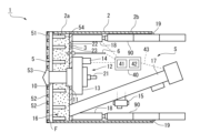
- FIG. 2 is a cross-sectional view illustrating the internal structure of a shield tunneling machine.
- 4 is a cross-sectional view illustrating the configuration of an exploration jig and a measurement sensor.
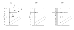
- FIG. 1 is an explanatory diagram of a face displacement measurement method using an in-machine measurement method, in which (a) is an explanatory diagram during excavation, (b) is an explanatory diagram of insertion of the detection tool, and (c) is an explanatory diagram during displacement measurement.
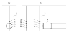
- 1 is an explanatory diagram of a pre-installation type face displacement measurement method, in which (a) is a horizontal cross-sectional view and (b) is a vertical cross-sectional view.
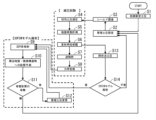
- 10 is a flowchart illustrating the procedure of a system for setting controlled earth pressure. 1 is a graph showing the relationship between mud pressure and horizontal displacement in a depressurization test.
- FIG. 2 is an explanatory diagram for explaining the concept of an FEM model.
- FIG. 1 is a vertical cross-sectional side view showing an embodiment of the present invention.
- an earth pressure shield 1 as a shield tunneling machine of this embodiment includes a skin plate (shield body tube) 2, a bulkhead 3, a cutter head 5, a cutter rotating shaft 10, a cutter driving unit 12, a chamber 16, an earth removal device 17, a shield propulsion jack 18, a mud material supply pipe 21, a pressure gauge 22, a water pressure gauge 23, and a control unit 40 including an analysis unit 41 and a setting unit 42 arranged inside an operation room or the like.
- the cutter head 5 has cutter spokes 51, a number of cutter bits 52, etc. provided on the front surface of the cutter spokes 51, a fishtail bit 53 provided in the center of the front surface of the cutter spokes 51, and a number of stirring blades 54, etc. provided on the back surface of the cutter spokes 51.
- the cutter head 5 is attached integrally to the cutter shaft 10.
- the cutter shaft 10 is rotatably supported by a bearing 11 provided in the partition 3 and a bearing provided at the rear of a gear box 13 described below.
- the cutter shaft 10 is connected to a cutter drive unit 12.
- the cutter drive unit 12 has a gear box 13 installed on the rear side of the partition 3, a rotary drive source 14 connected to the gear box 13, and a reduction gear (placed in the gear box 13; not shown) interposed between the output shaft of the rotary drive source 14 and the cutter shaft 10.
- the chamber 16 is formed in a space surrounded by the hood portion 2a of the skin plate 2, the partition wall 3, and the face F.
- a screw conveyor for example, is used as the soil discharge device 17.
- the mud intake port of the soil discharge device 17 is opened and installed so as to face the chamber 16.
- the soil discharge device 17 also functions as a mud pressure changing means.
- an erector 15 for assembling the segments 90 is installed in the tail portion 2b of the skin plate 2. Furthermore, multiple shield propulsion jacks 18 are installed at required intervals in the circumferential direction inside the skin plate 2. In addition, a tail seal 19 is provided at the rear end of the skin plate 2.
- the earth pressure shield 1 as the shield tunneling machine of this embodiment further includes displacement measurement means 6, 7 for measuring the displacement of the tunnel face or the area around the tunnel face.
- displacement measurement means 6, 7 for measuring the displacement of the tunnel face or the area around the tunnel face.
- the on-board displacement measuring means 6 is composed of a rod-shaped probe 61 that is long enough to penetrate the bulkhead 3 and have its tip 61a reach the face F, a hydraulic chuck 63 that grips and releases the probe 61, thereby moving and releasing it as the jacks 62, 62 extend and retract, a detection unit 64 that is attached integrally to the end of the probe 61, a guide 65 that supports the sliding movement of the detection unit 64, a displacement sensor 66 that measures the amount of displacement of the probe 61 by measuring the distance from the detection unit 64, a water stop device 67 for the probe 61, and water stop valves 68, 68.
- the exploration jig 61 retreats when the jacks 62, 62 extend, and advances when the jack 62 retracts.
- the exploration jig 61 is free. Therefore, in the open state (where the exploration jig 61 can move freely), if the tip 61a of the exploration jig 61 is in contact with the face F, the exploration jig 61 moves (in the tunnel longitudinal direction) in accordance with the displacement of the face F.
- the mud pressure in the chamber 16 is reduced, causing the face F to protrude slightly, and the exploration jig 61 moves in the tunnel longitudinal direction toward the tunnel entrance.
- the operation procedure of the displacement measuring means 6 having the detection jig 61 and the displacement sensor 66 in the reduced pressure test of this embodiment will be described with reference to FIG. 2 and FIGS. 1.
- the exploration tool 61 is retracted to the partition wall 3 position (FIG. 3(a)).
- the detection jig 61 is gripped by the hydraulic chuck 63 and slid to a position where the tip 61a contacts the face F (see FIG. 3(b)).
- the jack 62 is retracted. 3.
- the hydraulic chuck 63 is released. 4.
- the soil removal means is operated at a slow speed to gradually reduce the soil pressure in the chamber 16. 5.
- the displacement pushes the detection jig 61 into the shield (see FIG. 3(c)).
- a measuring device (a detection unit 64 and a displacement sensor 66) is attached inside the shield of the detection jig 61. The amount of displacement is measured by the displacement sensor 66 through the detection unit 64. 7. The measured value is sent from the displacement sensor 66 to the PC.
- the mud pressure in the chamber 16 is measured by the pressure gauge 22 provided in the bulkhead 3. 8. Using the above procedure, the relationship between the mud pressure in the chamber 16 and the face F displacement is obtained. 9.
- the decompression test shall be stopped when all or part of the transition region in the face displacement (including the yield point) has become apparent.
- the soil discharge means is reversed to return the soil to the chamber 16, thereby increasing the soil pressure to the initial state.
- the detection jig 61 is gripped by the hydraulic chuck 63, and the detection jig 61 is pulled back by operating the jack 62 to retract the detection jig 61 to the partition wall 3 position (FIG. 3(a)).
- the jack 62 is extended.
- the configuration of the on-board displacement measurement means 6 described above, which measures displacement, can be replaced with pre-installed multi-stage inclinometers (or layer-specific settlement gauges) 71-74, 75-78, which are installed in advance from the ground. That is, the pre-installed displacement measurement means 7 is configured by installing multiple multi-stage inclinometers 71-74, 75-78 at a predetermined depth from the ground surface, as shown in FIG. 4.
- the installation positions preferably include, for example, in addition to the vicinity of the face of the planned tunnel excavation position, directly above it and positions shifted to the left and right (and directly above it).
- multi-stage inclinometers 71-74 and layer-by-layer settlement meters in advance from the ground in the cross section where the shield is scheduled to pass, temporarily halting shield excavation just before the measuring device, and conducting a decompression test.
- These multi-stage inclinometers 71-74 are preferably buried at a specified interval in the area where the shield is scheduled to pass. In this case, it is preferable to bury them at intervals narrower than the conventional boring interval (200 (m)).
- the earth pressure shield 1 further includes a control unit 40.
- the control unit 40 is, for example, a general-purpose personal computer having a memory, a CPU, an SSD, and the like.
- the control unit 40 sets the managed earth pressure of the earth pressure shield 1 and controls the excavation. That is, during excavation, the earth pressure is changed by discharging the mud using the soil discharge device 17 (screw conveyor) as a mud pressure changing means while the earth pressure is changed by discharging the mud using the soil discharge device 17 (screw conveyor), and at the same time the mud pressure is measured using the pressure gauge 22. Furthermore, the water pressure is measured using the water pressure gauge 23.
- control unit processing unit 40 that controls the excavation of the earth pressure shield 1.
- control unit can also be called a "computing unit”.
- the control unit 40 of this embodiment further has a function as an analysis unit 41 that analyzes the deformation characteristics of the ground based on the measured mud pressure and the measured displacement of the face (e.g. horizontal displacement), and a function as a setting unit 42 that sets the controlled earth pressure based on the analyzed deformation characteristics.
- the control unit 40 is connected to input means such as a keyboard and a mouse, as well as inputs of the mud pressure value from the pressure gauge 22, the water pressure value from the water pressure gauge 23, and the input value (displacement) from the displacement sensor 66 via a communication cable 43. Furthermore, the control unit 40 is connected to a monitor or a separate PC for excavation management as output means.
- the functions of the analysis unit 41 and the setting unit 42 will be explained in the control flow explained next.
- the above-mentioned pressure gauge 22, the soil removal device 17 as a mud pressure changing means, the displacement measuring means 6 (7), and the control unit 40 including the analysis unit 41 and the setting unit 42 constitute the controlled soil pressure setting system S of the present invention.
- a water pressure gauge 23 is provided.
- step S1 First, based on the initial calculated earth pressure set by a boring test or the like (step S1), an initial value of the controlled earth pressure is set (step S2). Then, the shield is advanced according to this initial value of the controlled earth pressure (step S3). That is, in the initial stage after the shield starts advancing (before the decompression test is performed), the controlled earth pressure is set based on the theoretical earth pressure calculated from the soil constants obtained by the preliminary soil survey. Alternatively, the mechanical constants of the ground obtained by the preliminary soil survey are given to the 3D-FEM model, and the controlled earth pressure is set from the relationship between the earth pressure and the displacement of the ground.
- step S4 the mud pressure in the chamber is reduced. That is, when excavation is stopped, such as when assembling the segments 90, the screw conveyor is rotated at a slow speed to gradually discharge the mud in the chamber 16 and reduce the pressure.
- the mud pressure is measured by the pressure gauge 22.
- the water pressure is measured by the water pressure gauge 23.
- step S5 the displacement of the face F is directly measured by the displacement measuring means 6, 7 (step S5).
- step S6 Based on the measured mud pressure and face displacement (e.g. horizontal displacement), the deformation characteristics are grasped (step S6). That is, the mud pressure-face displacement is plotted on a graph to obtain the deformation characteristics.
- the mechanical constants of the ground are analyzed by back analysis (step S7) (step S8).
- step S9 uses the mechanical constants of the ground analyzed by the depressurization test, a 3D-FEM analysis is performed as shown in Fig. 7 (step S9). Then, by this 3D-FEM model analysis, the effects on the surrounding ground and adjacent structures are predicted (step S10).
- step S8 the mechanical constants of the ground are calculated (step S8) by back analysis of a ground model based on the in-situ boundary conditions such as the ground structure assumed from boring surveys and the measured water pressure (step S7).
- a 3D-FEM analysis is performed as shown in Figure 7 (step S9).
- step S11 the presence or absence of harmful effects is determined by judging whether the amount of ground surface subsidence, etc. is below the allowable displacement amount (step S11). If harmful effects are found ("Yes” in step S11), the controlled earth pressure is changed (step S12) and the analysis is repeated (steps S9 to S11). On the other hand, if harmless ("No" in step S11), the process returns to step S2 and the controlled earth pressure setting system S is executed at the next position and time.
- mechanical constants include, for example, Young's modulus, Poisson's ratio, internal friction angle, and cohesion.
- a rational simulation of behavior is possible by performing a simulation using an FEM model based on the ground characteristics obtained based on this on-site behavior.
- a rational simulation based on the above-mentioned on-site behavior makes it possible to predict surface subsidence and the impact on adjacent structures in advance and more accurately, minimizing the impact on the surrounding area or setting managed earth pressure that corresponds to regulatory values for ground displacement, etc.
- step S13 the yield point earth pressure is obtained by analysis from the mud earth pressure-displacement graph as shown in FIG. 6 (step S13). That is, the analysis unit 41 of the control unit 40 finds the point where the gradient suddenly increases, regards this point as the yield point, and obtains the active earth pressure. For example, an approximation line can be obtained from multiple plots in the elastic region by the least squares method, and an approximation line can be obtained from multiple plots in the plastic region by the least squares method, and the intersection of these can be regarded as the yield point.
- step S14 it can be estimated that the transition region has been entered by the appearance of consecutive plots that are significantly different from the moving average. Then, if a 3D-FEM model analysis is required due to the presence of buildings nearby ("required” in step S14), the impact on the surrounding ground and adjacent structures is predicted by the 3D-FEM analysis (step S10). If a 3D-FEM model analysis is not required ("not required” in step S14), the controlled earth pressure is reset based on the active earth pressure (step S2). Specifically, since it is necessary to ensure that the controlled earth pressure in the chamber 16 during excavation does not fall below the active earth pressure plus water pressure, the lower limit of the controlled earth pressure is set to the calculated active earth pressure plus water pressure plus ⁇ (0-20 kN/ m2 ).
- the upper limit of the controlled earth pressure may be theoretically calculated using C and ⁇ calculated backward from the active earth pressure (yield point earth pressure), or may be set to a value that further takes into account the above lower limit and the range of construction fluctuations.
- the 3D-FEM model analysis is carried out (step S9).
- the observed digital values are compared with the digital values (analytical values) obtained by analysis using a model ground, and the model is constantly corrected to create a model ground that is consistent with changes in the ground as the shield face advances (the so-called "digital twin").
- the controlled earth pressure setting system S of this embodiment is a controlled earth pressure setting system S for an earth pressure shield 1 as a shield tunneling machine, and includes a pressure gauge 22 that measures the mud pressure in the chamber 16, an earth removal device 17 as a mud pressure changing means for changing the mud pressure in the chamber 16, displacement measuring means 6, 7 that measure the displacement of the face F, an analysis unit 41 that analyzes the deformation characteristics of the ground based on the measured mud pressure and the measured displacement of the face, and a setting unit 42 that sets the controlled earth pressure based on the analyzed deformation characteristics. Because of this configuration, the controlled earth pressure setting system S can set the controlled earth pressure by directly measuring the relationship between the mud pressure in the chamber and the displacement of the face, rather than setting the controlled earth pressure based on assumptions or estimates.
- the mud pressure in the chamber 16 is reduced by discharging a small amount of mud using the soil discharge device 17, which serves as a mud pressure changing means, and the active earth pressure can be found from the deformation of the ground by the analysis unit 41. Therefore, when the shield machine stops excavating - for example, when the segments are being assembled - the pressure in the chamber 16 is slightly reduced to slightly displace the face F toward the chamber 16, and the active earth pressure can be directly found by analyzing the yield point from the transition region in the graph showing the relationship between the mud pressure and the face displacement.
- the displacement measuring means 6 also includes an exploration tool 61 that penetrates the bulkhead 3 to reach the face F, and a displacement sensor 66 that measures the displacement of the exploration tool 61 on the minehead side of the bulkhead 3. Therefore, the exploration tool 61 and the displacement sensor 66 can directly measure the displacement of the face F from inside the machine. Therefore, the displacement sensor 66 itself is less likely to become dirty and less likely to break down.
- the displacement measuring means 6 may be structured so as not to penetrate the bulkhead 3 by installing the exploration tool, displacement sensor, etc. in the chamber 16 in front of the bulkhead.
- the multi-stage inclinometer and/or layer-specific settlement meter 71-78 are installed in advance as the displacement measurement means 7 in the ground to be excavated, it is possible to directly measure the displacement over a wide area, not only around the face F but also to the measurement point near the ground surface.
- the analysis unit 41 estimates the mechanical constants of the ground by inverse analysis based on the analyzed deformation characteristics of the ground, updates the FEM model using the estimated mechanical constants of the ground, and uses the updated FEM model to predict the impact on the surrounding ground and/or structures. Therefore, although it is not completely real-time, by updating the FEM model at intervals that are close to real-time updates and much shorter than conventional intervals, it is possible to bring the ground characteristics much closer to the actual characteristics. This makes it possible to realize predictions and impact assessments using the FEM model with extremely high accuracy.
- the detection tool 61 penetrates the bulkhead 3 to reach the face F, but this is not limited thereto, and the detection tool 61 does not have to penetrate the bulkhead 3 as long as it is configured to be able to move back and forth within the chamber 16.
- the water pressure gauge 23 is attached to the bulkhead 3, but this is not limited thereto, and it may be attached to the skin plate 2, cutter head 5, etc., for example.
- control flow is divided into processes according to whether 3D-FEM model analysis is required or not, but this is not limited to this, and it is of course possible to configure the system so that 3D-FEM model analysis is always performed.
Landscapes
- Engineering & Computer Science (AREA)
- Mining & Mineral Resources (AREA)
- Environmental & Geological Engineering (AREA)
- Life Sciences & Earth Sciences (AREA)
- General Life Sciences & Earth Sciences (AREA)
- Geochemistry & Mineralogy (AREA)
- Geology (AREA)
- Excavating Of Shafts Or Tunnels (AREA)
Abstract
L'invention concerne un système de réglage pour une pression de terre gérée d'un bouclier excavateur, qui règle la pression de terre gérée non pas par le biais d'hypothèses ou d'estimations, mais en mesurant directement la relation entre le déplacement du front de taille et la pression de la boue dans une chambre. Il en est de même d'un système de réglage pour une pression de terre gérée dans, comme un bouclier excavateur, un bouclier à pression de terre (1). Ce système de réglage pour une pression de terre gérée comprend : un manomètre (22) pour mesurer la pression de la boue dans une chambre (16) ; un appareil d'élimination de terre (17) en tant que moyen de modification de pression de la boue pour modifier la pression de la boue dans la chambre (16) ; un moyen de mesure de déplacement (6, 7) pour mesurer le déplacement d'un front de taille F ; une unité d'analyse (41) qui analyse une caractéristique de déformation du sol sur la base de la pression de la boue mesurée et du déplacement mesuré du front de taille ; et une unité de réglage (42) pour régler la pression de terre gérée sur la base de la caractéristique de déformation analysée.
Applications Claiming Priority (2)
| Application Number | Priority Date | Filing Date | Title |
|---|---|---|---|
| JP2023107921A JP7496916B1 (ja) | 2023-06-30 | 2023-06-30 | 管理土圧の設定システム |
| JP2023-107921 | 2023-06-30 |
Publications (1)
| Publication Number | Publication Date |
|---|---|
| WO2025004541A1 true WO2025004541A1 (fr) | 2025-01-02 |
Family
ID=91332587
Family Applications (1)
| Application Number | Title | Priority Date | Filing Date |
|---|---|---|---|
| PCT/JP2024/017058 Ceased WO2025004541A1 (fr) | 2023-06-30 | 2024-05-08 | Système de réglage pour pression de terre gérée |
Country Status (3)
| Country | Link |
|---|---|
| JP (1) | JP7496916B1 (fr) |
| TW (1) | TW202517892A (fr) |
| WO (1) | WO2025004541A1 (fr) |
Families Citing this family (1)
| Publication number | Priority date | Publication date | Assignee | Title |
|---|---|---|---|---|
| JP7557644B1 (ja) * | 2024-03-22 | 2024-09-27 | 大豊建設株式会社 | 管理土圧の逐次更新システム |
Citations (9)
| Publication number | Priority date | Publication date | Assignee | Title |
|---|---|---|---|---|
| JPS58207492A (ja) * | 1982-05-28 | 1983-12-02 | 石川島播磨重工業株式会社 | シ−ルド掘進機の切羽安定制御方法 |
| JPS6032493U (ja) * | 1983-08-12 | 1985-03-05 | 三菱重工業株式会社 | 障害物探査装置 |
| JP2002147170A (ja) * | 2000-11-15 | 2002-05-22 | Ishikawajima Harima Heavy Ind Co Ltd | シールド掘進機の掘削管理装置 |
| JP2003013687A (ja) * | 2001-06-28 | 2003-01-15 | Daiho Constr Co Ltd | シールド掘進時における地表面ないしは路盤の変位を測定する方法および路盤変位管理方法ならびに路盤変位管理装置 |
| JP2006233677A (ja) * | 2005-01-27 | 2006-09-07 | Kajima Corp | 掘進機および計測装置 |
| JP2008031703A (ja) * | 2006-07-27 | 2008-02-14 | Ohbayashi Corp | 土圧式シールド機による小土被り区間の掘進方法及びチャンバ内の圧力管理方法 |
| JP2017014878A (ja) * | 2015-07-07 | 2017-01-19 | 三井住友建設株式会社 | シールド掘進機、及びトンネルの構築方法 |
| JP2021067059A (ja) * | 2019-10-21 | 2021-04-30 | 株式会社奥村組 | シールド掘進機 |
| JP2021188294A (ja) * | 2020-05-27 | 2021-12-13 | 鹿島建設株式会社 | シールド掘進機の制御システム |
-
2023
- 2023-06-30 JP JP2023107921A patent/JP7496916B1/ja active Active
-
2024
- 2024-05-08 WO PCT/JP2024/017058 patent/WO2025004541A1/fr not_active Ceased
- 2024-06-20 TW TW113122893A patent/TW202517892A/zh unknown
Patent Citations (9)
| Publication number | Priority date | Publication date | Assignee | Title |
|---|---|---|---|---|
| JPS58207492A (ja) * | 1982-05-28 | 1983-12-02 | 石川島播磨重工業株式会社 | シ−ルド掘進機の切羽安定制御方法 |
| JPS6032493U (ja) * | 1983-08-12 | 1985-03-05 | 三菱重工業株式会社 | 障害物探査装置 |
| JP2002147170A (ja) * | 2000-11-15 | 2002-05-22 | Ishikawajima Harima Heavy Ind Co Ltd | シールド掘進機の掘削管理装置 |
| JP2003013687A (ja) * | 2001-06-28 | 2003-01-15 | Daiho Constr Co Ltd | シールド掘進時における地表面ないしは路盤の変位を測定する方法および路盤変位管理方法ならびに路盤変位管理装置 |
| JP2006233677A (ja) * | 2005-01-27 | 2006-09-07 | Kajima Corp | 掘進機および計測装置 |
| JP2008031703A (ja) * | 2006-07-27 | 2008-02-14 | Ohbayashi Corp | 土圧式シールド機による小土被り区間の掘進方法及びチャンバ内の圧力管理方法 |
| JP2017014878A (ja) * | 2015-07-07 | 2017-01-19 | 三井住友建設株式会社 | シールド掘進機、及びトンネルの構築方法 |
| JP2021067059A (ja) * | 2019-10-21 | 2021-04-30 | 株式会社奥村組 | シールド掘進機 |
| JP2021188294A (ja) * | 2020-05-27 | 2021-12-13 | 鹿島建設株式会社 | シールド掘進機の制御システム |
Also Published As
| Publication number | Publication date |
|---|---|
| TW202517892A (zh) | 2025-05-01 |
| JP2025006882A (ja) | 2025-01-17 |
| JP7496916B1 (ja) | 2024-06-07 |
Similar Documents
| Publication | Publication Date | Title |
|---|---|---|
| KR101745153B1 (ko) | 토압 균형식 tbm 설계, 연구를 위한 굴착과 배토과정 모사 시험장치,시험방법 및 분석 시스템 | |
| CN111946356B (zh) | 超长距离硬岩顶管施工方法 | |
| JP7496916B1 (ja) | 管理土圧の設定システム | |
| CN112101621A (zh) | 一种基于离散变量的软土地层盾构施工地表变形预测方法 | |
| JP7648811B1 (ja) | 管理土圧の設定システム | |
| CN114645715B (zh) | 一种区间盾构始发及接收施工方法 | |
| JP7557644B1 (ja) | 管理土圧の逐次更新システム | |
| CN113653496B (zh) | 一种泥水盾构隧道掘进全过程稳定方法 | |
| JP7624543B1 (ja) | 管理土圧の設定システム | |
| JP7648810B1 (ja) | 切羽近傍性状計測装置 | |
| JP5048601B2 (ja) | チャンバ内土砂流動計測装置及びシールド掘進機 | |
| JP2017190640A (ja) | 切羽押圧力制御回転掘進機 | |
| CN107461208B (zh) | 一种用于倾斜矿体上的联络管线井及施工方法 | |
| JPS6220359B2 (fr) | ||
| JP4973051B2 (ja) | 土圧式シールド機による小土被り区間の掘進方法及びチャンバ内の圧力管理方法 | |
| JPH0452397A (ja) | シールド機の掘進制御方法 | |
| KR20230016946A (ko) | 장거리 시공이 가능한 터널 굴진 장치 및 방법 | |
| JP2019143383A (ja) | 操作推定装置 | |
| JP2022134426A (ja) | 裏込注入システム | |
| JP2022144160A (ja) | トンネル構築時の地盤が受ける影響の評価方法 | |
| JP7712503B1 (ja) | 土圧の管理システム | |
| CN204646225U (zh) | 盾构地层适应性测试仪 | |
| CN111693675A (zh) | 可模拟穿越既有构筑物的隧道非开挖施工试验装置及方法 | |
| CN119437543B (zh) | 一种盾构机掘进水土荷载的测试平台及综合评估方法 | |
| JP2024168123A (ja) | 土層分布検知方法 |
Legal Events
| Date | Code | Title | Description |
|---|---|---|---|
| 121 | Ep: the epo has been informed by wipo that ep was designated in this application |
Ref document number: 24831414 Country of ref document: EP Kind code of ref document: A1 |
|
| NENP | Non-entry into the national phase |
Ref country code: DE |
|
| 122 | Ep: pct application non-entry in european phase |
Ref document number: 24831414 Country of ref document: EP Kind code of ref document: A1 |