WO2025004614A1 - Substrat fibreux renforcé - Google Patents
Substrat fibreux renforcé Download PDFInfo
- Publication number
- WO2025004614A1 WO2025004614A1 PCT/JP2024/018649 JP2024018649W WO2025004614A1 WO 2025004614 A1 WO2025004614 A1 WO 2025004614A1 JP 2024018649 W JP2024018649 W JP 2024018649W WO 2025004614 A1 WO2025004614 A1 WO 2025004614A1
- Authority
- WO
- WIPO (PCT)
- Prior art keywords
- resin
- fiber
- reinforced
- thermoplastic resin
- fiber substrate
- Prior art date
- Legal status (The legal status is an assumption and is not a legal conclusion. Google has not performed a legal analysis and makes no representation as to the accuracy of the status listed.)
- Ceased
Links
Images


Classifications
-
- B—PERFORMING OPERATIONS; TRANSPORTING
- B29—WORKING OF PLASTICS; WORKING OF SUBSTANCES IN A PLASTIC STATE IN GENERAL
- B29B—PREPARATION OR PRETREATMENT OF THE MATERIAL TO BE SHAPED; MAKING GRANULES OR PREFORMS; RECOVERY OF PLASTICS OR OTHER CONSTITUENTS OF WASTE MATERIAL CONTAINING PLASTICS
- B29B11/00—Making preforms
- B29B11/14—Making preforms characterised by structure or composition
- B29B11/16—Making preforms characterised by structure or composition comprising fillers or reinforcement
-
- B—PERFORMING OPERATIONS; TRANSPORTING
- B32—LAYERED PRODUCTS
- B32B—LAYERED PRODUCTS, i.e. PRODUCTS BUILT-UP OF STRATA OF FLAT OR NON-FLAT, e.g. CELLULAR OR HONEYCOMB, FORM
- B32B5/00—Layered products characterised by the non- homogeneity or physical structure, i.e. comprising a fibrous, filamentary, particulate or foam layer; Layered products characterised by having a layer differing constitutionally or physically in different parts
- B32B5/22—Layered products characterised by the non- homogeneity or physical structure, i.e. comprising a fibrous, filamentary, particulate or foam layer; Layered products characterised by having a layer differing constitutionally or physically in different parts characterised by the presence of two or more layers which are next to each other and are fibrous, filamentary, formed of particles or foamed
- B32B5/24—Layered products characterised by the non- homogeneity or physical structure, i.e. comprising a fibrous, filamentary, particulate or foam layer; Layered products characterised by having a layer differing constitutionally or physically in different parts characterised by the presence of two or more layers which are next to each other and are fibrous, filamentary, formed of particles or foamed one layer being a fibrous or filamentary layer
- B32B5/26—Layered products characterised by the non- homogeneity or physical structure, i.e. comprising a fibrous, filamentary, particulate or foam layer; Layered products characterised by having a layer differing constitutionally or physically in different parts characterised by the presence of two or more layers which are next to each other and are fibrous, filamentary, formed of particles or foamed one layer being a fibrous or filamentary layer another layer next to it also being fibrous or filamentary
-
- B—PERFORMING OPERATIONS; TRANSPORTING
- B32—LAYERED PRODUCTS
- B32B—LAYERED PRODUCTS, i.e. PRODUCTS BUILT-UP OF STRATA OF FLAT OR NON-FLAT, e.g. CELLULAR OR HONEYCOMB, FORM
- B32B5/00—Layered products characterised by the non- homogeneity or physical structure, i.e. comprising a fibrous, filamentary, particulate or foam layer; Layered products characterised by having a layer differing constitutionally or physically in different parts
- B32B5/22—Layered products characterised by the non- homogeneity or physical structure, i.e. comprising a fibrous, filamentary, particulate or foam layer; Layered products characterised by having a layer differing constitutionally or physically in different parts characterised by the presence of two or more layers which are next to each other and are fibrous, filamentary, formed of particles or foamed
- B32B5/24—Layered products characterised by the non- homogeneity or physical structure, i.e. comprising a fibrous, filamentary, particulate or foam layer; Layered products characterised by having a layer differing constitutionally or physically in different parts characterised by the presence of two or more layers which are next to each other and are fibrous, filamentary, formed of particles or foamed one layer being a fibrous or filamentary layer
- B32B5/28—Layered products characterised by the non- homogeneity or physical structure, i.e. comprising a fibrous, filamentary, particulate or foam layer; Layered products characterised by having a layer differing constitutionally or physically in different parts characterised by the presence of two or more layers which are next to each other and are fibrous, filamentary, formed of particles or foamed one layer being a fibrous or filamentary layer impregnated with or embedded in a plastic substance
-
- D—TEXTILES; PAPER
- D04—BRAIDING; LACE-MAKING; KNITTING; TRIMMINGS; NON-WOVEN FABRICS
- D04H—MAKING TEXTILE FABRICS, e.g. FROM FIBRES OR FILAMENTARY MATERIAL; FABRICS MADE BY SUCH PROCESSES OR APPARATUS, e.g. FELTS, NON-WOVEN FABRICS; COTTON-WOOL; WADDING ; NON-WOVEN FABRICS FROM STAPLE FIBRES, FILAMENTS OR YARNS, BONDED WITH AT LEAST ONE WEB-LIKE MATERIAL DURING THEIR CONSOLIDATION
- D04H3/00—Non-woven fabrics formed wholly or mainly of yarns or like filamentary material of substantial length
- D04H3/005—Synthetic yarns or filaments
- D04H3/009—Condensation or reaction polymers
- D04H3/011—Polyesters
-
- D—TEXTILES; PAPER
- D04—BRAIDING; LACE-MAKING; KNITTING; TRIMMINGS; NON-WOVEN FABRICS
- D04H—MAKING TEXTILE FABRICS, e.g. FROM FIBRES OR FILAMENTARY MATERIAL; FABRICS MADE BY SUCH PROCESSES OR APPARATUS, e.g. FELTS, NON-WOVEN FABRICS; COTTON-WOOL; WADDING ; NON-WOVEN FABRICS FROM STAPLE FIBRES, FILAMENTS OR YARNS, BONDED WITH AT LEAST ONE WEB-LIKE MATERIAL DURING THEIR CONSOLIDATION
- D04H3/00—Non-woven fabrics formed wholly or mainly of yarns or like filamentary material of substantial length
- D04H3/08—Non-woven fabrics formed wholly or mainly of yarns or like filamentary material of substantial length characterised by the method of strengthening or consolidating
- D04H3/16—Non-woven fabrics formed wholly or mainly of yarns or like filamentary material of substantial length characterised by the method of strengthening or consolidating with bonds between thermoplastic filaments produced in association with filament formation, e.g. immediately following extrusion
-
- D—TEXTILES; PAPER
- D06—TREATMENT OF TEXTILES OR THE LIKE; LAUNDERING; FLEXIBLE MATERIALS NOT OTHERWISE PROVIDED FOR
- D06M—TREATMENT, NOT PROVIDED FOR ELSEWHERE IN CLASS D06, OF FIBRES, THREADS, YARNS, FABRICS, FEATHERS OR FIBROUS GOODS MADE FROM SUCH MATERIALS
- D06M17/00—Producing multi-layer textile fabrics
-
- B—PERFORMING OPERATIONS; TRANSPORTING
- B29—WORKING OF PLASTICS; WORKING OF SUBSTANCES IN A PLASTIC STATE IN GENERAL
- B29K—INDEXING SCHEME ASSOCIATED WITH SUBCLASSES B29B, B29C OR B29D, RELATING TO MOULDING MATERIALS OR TO MATERIALS FOR MOULDS, REINFORCEMENTS, FILLERS OR PREFORMED PARTS, e.g. INSERTS
- B29K2105/00—Condition, form or state of moulded material or of the material to be shaped
- B29K2105/06—Condition, form or state of moulded material or of the material to be shaped containing reinforcements, fillers or inserts
- B29K2105/08—Condition, form or state of moulded material or of the material to be shaped containing reinforcements, fillers or inserts of continuous length, e.g. cords, rovings, mats, fabrics, strands or yarns
Definitions
- the present invention relates to a reinforcing fiber substrate and a manufacturing method thereof.
- the present invention also relates to a preform material and a fiber-reinforced composite material having this reinforcing fiber substrate, and to manufacturing methods thereof.
- Fiber-reinforced composite materials are lightweight, strong, and rigid, and are therefore used in a wide range of fields, including sports and leisure applications such as fishing rods and golf shafts, and industrial applications such as automobiles and aircraft.
- Fiber-reinforced composite materials can be manufactured, for example, by impregnating a reinforced fiber substrate (particularly a reinforced fiber substrate made of carbon fiber) with a matrix resin and then curing the substrate.
- Methods for molding fiber-reinforced composite materials include a method in which a reinforced fiber substrate is impregnated with resin in advance and formed into a sheet-like prepreg (intermediate substrate), as well as a method in which a reinforced fiber substrate placed in a mold is impregnated with liquid resin (i.e., uncured curable resin or molten thermoplastic resin) and cured or solidified to obtain a fiber-reinforced composite material (resin transfer molding method, RTM method).
- liquid resin i.e., uncured curable resin or molten thermoplastic resin
- Reinforced fiber substrates often have multiple reinforcing fiber layers (particularly reinforcing fiber sheets).
- reinforcing fiber layers include fabrics woven with reinforcing fibers as warp and weft threads in a plain weave or satin weave. In such fabrics, for example, the reinforcing fibers as warp threads and the reinforcing fibers as weft threads run perpendicular to each other.
- Non-crimp fabric can also be used as the reinforcing fiber substrate.
- non-crimp fabric multiple reinforcing fiber layers made of reinforcing fibers aligned in one direction are stacked, and these stacked reinforcing fiber layers are sewn together with a stitch thread as an auxiliary thread.
- non-crimp fabric a stack of reinforcing fiber sheets made of reinforcing fibers aligned in one direction is integrated by being sewn together with an auxiliary thread (particularly called a stitch thread) that penetrates the stack in the thickness direction.
- a resin material layer such as a nonwoven fabric.
- the resin material layer is generally composed of thermoplastic resin fibers.
- a nonwoven fabric containing thermoplastic resin fibers as a resin material layer can be disposed on and/or between the reinforced fiber layers.
- This resin material layer can provide advantageous effects in terms of interlaminar fracture toughness, impact resistance, resin permeability, and dimensional stability of the substrate.
- Patent document 2 describes an intermediate material intended to be combined with a thermosetting resin to produce a composite part.
- This intermediate material consists of a unidirectional layer of carbon fibres combined on each side with a web of thermoplastic fibres having a specific thickness.
- Patent Document 3 describes a reinforced fiber substrate, which has a reinforcing fiber assembly and a mesh-like resin material arranged on at least one surface thereof, the resin material being a copolymer polyamide containing at least two polyamide components selected from polyamide 6, polyamide 6-6, polyamide 6-10, polyamide 12, and polyamide 6-I, and the melting point of the resin material being within the range of 80 to 180°C.
- Fiber-reinforced substrates are required to have excellent microcrack resistance and sufficient mechanical strength for the fiber-reinforced composite materials produced from the fiber-reinforced substrate, as well as good molding robustness.
- the present invention aims to provide a reinforced fiber substrate having a resin material layer, which exhibits excellent microcrack resistance and sufficient mechanical strength, as well as good molding robustness.
- the present invention also aims to provide a preform material and a fiber-reinforced composite material having such a reinforced fiber substrate, as well as methods for producing these.
- Microcracks are small cracks of several to several tens of ⁇ m that can occur in fiber-reinforced composite materials used in aerospace applications. These microcracks tend to occur in environments where several hundred cycles of thermal shock are repeated, with rapid temperature changes from high temperatures of about 70 to 100°C to low temperatures of about -50 to -60°C.
- the matrix resin contained in the fiber-reinforced composite material tends to shrink as the temperature drops from high to low, but the deformation of the matrix resin is suppressed by the reinforcing fibers, which have a relatively low coefficient of linear thermal expansion compared to the matrix resin, and as a result, residual thermal stress accumulates inside the matrix resin. In this way, fatigue stress accumulates due to thermal shock cycles, and microcracks tend to occur.
- auxiliary threads and nonwoven fibers contained in reinforcing fiber substrates often have a different coefficient of linear thermal expansion from the matrix resin, and residual thermal stress concentrates at the interface of fiber-reinforced composite materials containing them, which tends to cause interfacial peeling and microcracks originating from the interface.
- ⁇ Aspect 1> One or more reinforcing fiber layers containing reinforcing fibers, and one or more resin material layers containing thermoplastic resin fibers, A reinforcing fiber substrate having The melting point of the thermoplastic resin is higher than 180°C and not higher than 250°C, and the weight average molecular weight Mw of the thermoplastic resin is 15,000 to 28,000. Reinforced fiber substrate.
- thermoplastic resin is a polyamide resin or a polyester resin.
- thermoplastic resin is a polyamide resin.
- thermoplastic resin is a polyamide resin.
- thermoplastic resin is a polyamide resin.
- 5 The reinforcing fiber substrate according to any one of aspects 1 to 4, wherein the average fiber diameter of the thermoplastic resin fibers is 1 ⁇ m to 60 ⁇ m.
- 6 The reinforcing fiber substrate according to any one of aspects 1 to 5, wherein the one or more resin material layers are made of a nonwoven fabric containing thermoplastic resin fibers.
- the reinforcing fiber substrate includes at least two reinforcing fiber layers that are stacked on top of each other, and the at least two reinforcing fiber layers are each composed of the reinforcing fibers aligned in one direction, and the at least two reinforcing fiber layers are sewn together by a stitch yarn as an auxiliary yarn.
- a preform material comprising the reinforcing fiber substrate according to any one of aspects 1 to 11 and a binder resin.
- ⁇ Aspect 13> A method for producing a preform material, comprising heating a composite comprising the reinforcing fiber substrate according to any one of aspects 1 to 11 and a binder resin under pressure.
- ⁇ Aspect 14> A fiber reinforced resin composite material having the reinforcing fiber substrate according to any one of aspects 1 to 11, and a matrix resin impregnated in the reinforcing fiber substrate.
- ⁇ Aspect 15> Impregnating the reinforcing fiber substrate according to any one of aspects 1 to 11 with a matrix resin; and The reinforcing fiber substrate impregnated with the matrix resin is subjected to a heat curing treatment to obtain a fiber reinforced composite material.
- the present invention provides a reinforced fiber substrate having a resin material layer, which exhibits excellent microcrack resistance, sufficient mechanical strength, and good molding robustness.
- the present invention also makes it possible to provide a preform material and a fiber-reinforced composite material having such a reinforcing fiber substrate, and further provides a method for producing these.
- FIG. 1 shows a schematic cross-sectional view of a reinforcing fiber substrate according to one embodiment of the present invention.
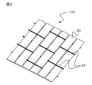
- FIG. 2 shows a schematic perspective view of the reinforcing fiber layer of FIG.
- FIG. 3 shows a schematic cross-sectional view of a reinforcing fiber substrate according to another embodiment of the present invention.
- FIG. 4 shows a perspective view of a plurality of reinforcing fiber layers of FIG.
- the reinforcing fiber substrate according to the present disclosure is One or more reinforcing fiber layers containing reinforcing fibers, and one or more resin material layers containing thermoplastic resin fibers, It has The melting point of the thermoplastic resin is higher than 180° C. and not higher than 250° C., and the weight average molecular weight Mw of the thermoplastic resin is 15,000 to 28,000.
- the reinforcing fiber substrate according to the present invention has one or more reinforcing fiber layers and one or more resin material layers.
- the reinforcing fiber substrate has a resin material layer, which can have advantageous effects on the interlaminar fracture toughness and impact resistance of the fiber-reinforced composite material.
- the reinforcing fiber substrate according to the present invention can be manufactured, for example, by a method including disposing a resin material layer on the surface of the reinforcing fiber layer based on the description of the present disclosure and known techniques.
- the reinforcing fiber substrate according to the present disclosure preferably has a basis weight of 100 to 2000 g/m 2 , more preferably 150 to 1500 g/m 2.
- the thickness of the reinforcing fiber substrate according to the present disclosure can be appropriately selected depending on the application of the molded product, and may be 0.1 to 2 mm, or 0.5 to 1.5 mm.
- the reinforced fiber substrate 10 includes a resin material layer 110 and a reinforced fiber layer 130, which are stacked on top of each other.
- the resin material layer 110 is disposed on the surface of the reinforced fiber layer 130.
- the resin material layer 110 includes thermoplastic resin fibers (fibers of a thermoplastic resin).
- the resin material layer 110 may be a nonwoven fabric made of thermoplastic resin fibers.
- the reinforced fiber layer 130 is made of reinforced fibers aligned in one direction. Although not shown, the reinforced fibers and/or the reinforced fiber layers may be connected to each other by auxiliary threads, thereby maintaining the integrity of the reinforced fiber layers and/or the reinforced fiber substrate.
- FIG. 2 shows a schematic perspective view of the reinforcing fiber layer 130 of FIG. 1.
- the resin material layer 110 is not shown.
- the reinforcing fiber layer 130 is a unidirectional woven fabric (UD-woven fabric).
- the unidirectional fabric is a so-called "blind fabric” and is composed of reinforcing fibers (particularly bundles of reinforcing fibers) 22 aligned in one direction and auxiliary threads 24.
- the reinforcing fibers 22 as warp threads and the auxiliary threads 24 as weft threads intertwine with each other to form the fabric.
- the reinforced fiber substrate may have multiple reinforcing fiber layers and/or resin material layers.
- the resin material layer may be laminated between multiple reinforcing fiber layers.
- FIG. 3 shows a cross-sectional schematic diagram of a reinforcing fiber substrate 30 according to another embodiment of the present invention.
- the reinforcing fiber substrate 30 includes a plurality of laminated resin material layers 310-316 and a plurality of reinforcing fiber layers 330, 340, and 350.
- the resin material layers 312 and 314 are disposed between the reinforcing fiber layers 330, 340, and 350, respectively.
- the resin material layers 310 and 316 are disposed in the outermost layers.
- the resin material layers 310-316 may be nonwoven fabrics composed of thermoplastic resin fibers.
- the reinforcing fiber layers 330, 340, and 350 are composed of reinforcing fibers aligned in one direction.
- the reinforcing fibers of the reinforcing fiber layers 330, 340, and 350 may be connected to each other by auxiliary threads, and/or the reinforcing fiber layers 330, 340, and 350 may be connected to each other by auxiliary threads, thereby maintaining the shape (particularly the sheet shape) of the reinforcing fiber layers 330, 340, and 350 and the integrity of the reinforcing fiber substrate 30.
- FIG. 4 is a perspective view corresponding to the reinforced fiber substrate of FIG. 3.
- the resin material layers 310 to 316 are not shown.
- the multiple reinforced fiber layers 330, 340, and 350 in FIG. 4 constitute a non-crimp fabric 40. That is, the reinforced fiber layers 330, 340, and 350 are each formed from reinforced fibers 42 aligned in one direction, and these laminated reinforced fiber layers are integrated by being sewn together with a stitch thread 44 as an auxiliary thread.
- the stitch thread 44 as an auxiliary thread can extend continuously in the thickness direction of the laminate across the multiple reinforced fiber layers. For simplicity, only a portion of the auxiliary thread is shown in FIG. 4. In the non-crimp fabric, bending of the reinforced fibers is less likely to occur, and the mechanical properties of the fiber-reinforced composite material manufactured from the reinforced fiber substrate can be further improved.
- the reinforcing fibers constituting each of the multiple reinforcing fiber layers extend in different directions. That is, the reinforcing fibers constituting the reinforcing fiber layer 330 extend along the direction L shown in FIG. 4, the reinforcing fibers constituting the reinforcing fiber 340 extend at an angle of approximately 90° to the direction L, and the reinforcing fibers constituting the reinforcing fiber 450 extend at an angle of approximately 45° to the direction L.
- the resin material layers 310-316 arranged on the reinforcing fiber layers can also be sewn together with the multiple reinforcing fiber layers using auxiliary thread 44.
- the reinforcing fiber layer includes reinforcing fibers.
- a reinforced fiber sheet can be used as the reinforced fiber layer, and in particular, a reinforced fiber sheet formed by processing continuous fiber bundles of reinforced fibers into a sheet shape can be used.
- the reinforced fiber layer is unidirectional (UD: Uni-directional). In other words, the reinforced fiber layer is formed from reinforced fibers aligned in one direction.
- the reinforcing fiber layer is a unidirectional woven fabric (UD-woven fabric) having reinforcing fibers aligned in one direction as warp threads and auxiliary threads as weft threads (see Figure 2 above).
- UD-woven fabric unidirectional woven fabric
- the reinforcing fiber substrate is a non-crimp fabric (NCF) (see FIG. 4 above).
- NCF non-crimp fabric
- the non-crimp fabric includes at least two reinforcing fiber layers that are stacked on top of each other, and each of the at least two reinforcing fiber layers is made of reinforcing fibers that are aligned in one direction, and the at least two reinforcing fiber layers are sewn together with a stitch thread that serves as an auxiliary thread.
- the extending direction of the reinforcing fibers in one of the at least two reinforcing fiber layers is different from the extending direction of the reinforcing fibers in the other reinforcing fiber layer.
- a plurality of reinforcing fiber layers made of reinforcing fibers aligned in one direction are stacked in sequence with the fiber axis directions changed from one another. This embodiment is preferable because it improves the isotropy of the reinforced fiber substrate.
- reinforcing fibers include carbon fibers, glass fibers, aramid fibers, boron fibers, metal fibers, etc.
- the reinforcing fibers are preferably carbon fibers.
- the average length of the reinforcing fibers is not particularly limited, but may be, for example, 5 cm to 100 m.
- the reinforcing fiber layer according to the present disclosure may have auxiliary yarns.
- the auxiliary yarns can serve to maintain the integrity of the reinforcing fiber layer and/or the reinforcing fiber substrate by connecting the reinforcing fibers and/or the reinforcing fiber layers to each other.
- the auxiliary yarns form wefts to the reinforcing fibers that serve as warp threads.
- the auxiliary yarns as wefts cross the reinforcing fibers that are aligned in one direction at an angle of approximately 90° to form a unidirectional fabric (see Figure 2 above).
- the auxiliary thread is a stitch thread.
- the stitch thread for example, sews together multiple reinforced fiber layers in a laminate in which multiple reinforced fiber layers made of reinforced fibers aligned in one direction are stacked (see FIG. 4 above).
- the auxiliary yarn preferably has a fineness of 1 dtex to 75 dtex, more preferably 15 dtex to 40 dtex.
- the auxiliary yarn comprises a fiber of polyolefin fiber, polyamide resin, polyester resin, cellulose fiber, polyethersulfone (PES) resin, or polyetherimide (PEI) resin, or a mixture thereof.
- the auxiliary yarn may be composed of at least one of these.
- the resin material layer can be laminated together with the reinforcing fiber layer to form a laminate, for example as illustrated in Figures 1 and 3.
- the resin material layer can be disposed between the reinforcing fiber layers.
- the resin material layer is adjacent to the reinforcing fiber layer, and in particular disposed on the surface of the reinforcing fiber layer.
- the resin material layer may be disposed, for example, on a major surface of the unidirectional fabric.
- the resin material layer may be disposed in the outermost layer (i.e., for example, on one or both main surfaces of a laminate consisting of multiple reinforced fiber layers) and/or may be disposed between multiple reinforced fiber layers that make up the non-crimp fabric.
- the resin material layer (particularly the nonwoven fabric) preferably has a thickness of 1 ⁇ m to 50 ⁇ m, more preferably 2 ⁇ m to 40 ⁇ m, and even more preferably 3 ⁇ m to 35 ⁇ m.
- the resin material layer has a basis weight of preferably 1 g/m 2 to 15 g/m 2 , more preferably 2 g/m 2 to 10 g/m 2 , and particularly preferably 4 g/m 2 to 6 g/m 2 .
- a resin material layer is disposed on the surface of the reinforced fiber layer. More specifically, one resin material layer or each of multiple resin material layers is disposed on the surface of one reinforced fiber layer or on the surface of any of the multiple reinforced fiber layers.
- the resin material layer is a sheet containing thermoplastic resin fibers, in particular a nonwoven fabric containing thermoplastic resin fibers.
- the resin material layer is a nonwoven fabric containing thermoplastic resin fibers, and more preferably, a nonwoven fabric made of thermoplastic resin fibers.
- the nonwoven fabric can be manufactured by the meltblowing method or the spunbonding method. By using the meltblowing method, a thinner nonwoven fabric containing thermoplastic resin fibers with a smaller fiber diameter can be manufactured compared to when the spunbonding method is used. On the other hand, when the spunbonding method is used, the fiber diameter is larger than that of the fibers manufactured by the meltblowing method, and therefore the strength and handling of the nonwoven fabric are excellent.
- the resin material layer is made of a long-fiber nonwoven fabric containing thermoplastic resin fibers.
- a long-fiber nonwoven fabric refers to one made of continuous thermoplastic resin fibers having a length of 1 m or more.
- the resin material layer includes fibers of a thermoplastic resin (also referred to as thermoplastic resin fibers).
- the mass ratio of the thermoplastic resin fibers to the resin material layer is preferably 50 mass% or more, more preferably 80 mass% or more, and particularly preferably 90 mass% or more.
- the resin material layer is made of thermoplastic resin fibers.
- thermoplastic resin constituting the thermoplastic resin fiber according to the present disclosure has a melting point of more than 180° C. and not more than 250° C. As described above, this makes it possible to provide a reinforcing fiber substrate having good molding robustness.
- the melting point of the thermoplastic resin may be 181°C or more, 182°C or more, or 183°C or more, and/or 245°C or less, 240°C or less, 235°C or less, 230°C or less, 225°C or less, or 220°C or less.
- the melting point of the thermoplastic resin is preferably 180°C to 240°C, more preferably 181°C to 230°C, and even more preferably 182°C to 220°C.
- the melting point of the thermoplastic resin fiber can be measured by a differential scanning calorimeter according to the standard JIS K7121 under the following conditions: Measurement temperature range: Room temperature to 250°C Heating rate: 5°C/min
- thermoplastic resin constituting the thermoplastic resin fiber according to the present invention has a weight average molecular weight (Mw) of 15,000 to 28,000. As described above, by limiting the molecular weight of the resin of the thermoplastic resin fiber to a relatively low range, the affinity (adhesion) with the matrix resin in the composite material is improved, and thereby good microcrack resistance is obtained.
- the thermoplastic resin constituting the thermoplastic resin fiber according to the present disclosure preferably has a number average molecular weight (Mn) of 10,000 to 15,000.
- the number average molecular weight (Mn) of the thermoplastic resin is more preferably 10,500 to 15,000, and particularly preferably 11,000 to 14,500.
- the polydispersity (Mw/Mn) of the thermoplastic resin constituting the thermoplastic resin fiber according to the present disclosure may be 1.00 to 2.50. This polydispersity is preferably 1.30 to 2.00, more preferably 1.40 to 1.80, and even more preferably 1.45 to 1.75.
- the polydispersity (Mw/Mn) of a thermoplastic resin can be calculated from the weight average molecular weight and number average molecular weight of the thermoplastic resin, which are determined by the GPC method.
- the present disclosure also includes an embodiment in which the resin material layer includes fibers of a thermoplastic resin that does not have a melting point, or is even constituted by a thermoplastic resin that does not have a melting point.
- the thermoplastic resin that does not have a melting point has a glass transition temperature of 180 to 230°C. That is, in one aspect included in the present disclosure, for the thermoplastic resin fibers of the resin material layer, the melting point of the thermoplastic resin is greater than 180°C and not greater than 250°C, and/or the thermoplastic resin has a glass transition temperature of 180 to 230°C.
- the glass transition temperature of a thermoplastic resin can be measured by a differential scanning calorimeter according to the standard JIS K7121 under the following conditions: Measurement temperature range: -50 to 300°C Heating rate: 10°C/min
- thermoplastic resins constituting the thermoplastic resin fibers include polyamide, polyimide, polyamide-imide, polyester, polybutadiene, polyurethane, polypropylene, polyetherimide (PEI), polysulfone, polyethersulfone (PES), polyphenylsulfone, polyphenylene sulfide (PPS), polyetherketone, polyetheretherketone (PEEK), polyarylamide, polyketone, polyphthalamide (PPA), polyphenylene ether, polybutylene terephthalate, polyethylene terephthalate, polyester-polyarylate, aramid, polybenzoxazole, and viscose.
- the thermoplastic resin fibers can include at least one of these thermoplastic resins, and are particularly formed from at least one of these thermoplastic resins.
- the thermoplastic resin constituting the thermoplastic resin fiber includes a polyamide resin or a polyester resin, and more preferably includes a polyamide resin (PA resin), and is particularly preferably a polyamide resin or a polyester resin, and more preferably is a polyamide resin (PA resin).
- PA resin polyamide resin
- PA resin polyamide resin
- PA11 and PA612 are more preferred, and PA11 is the most preferred.
- PA11 is the most preferred.
- the average fiber diameter of the thermoplastic resin fibers is 1 ⁇ m to 60 ⁇ m.
- the average fiber diameter of the thermoplastic resin fibers is within this range, a reinforcing fiber substrate having further improved resistance to microcracks can be obtained.
- the average fiber diameter is preferably 2 ⁇ m to 58 ⁇ m, more preferably 3 ⁇ m to 55 ⁇ m, particularly preferably 4 ⁇ m to 45 ⁇ m or even 5 ⁇ m to 42 ⁇ m. In one particularly preferred embodiment, the average fiber diameter is 1 ⁇ m to 12 ⁇ m, 3 ⁇ m to 10 ⁇ m, or even 4 ⁇ m to 8 ⁇ m.
- the average fiber diameter of a thermoplastic resin fiber can be determined by averaging the fiber diameter values measured for at least 30 fibers using an optical microscope.
- the present disclosure also includes a preform material having the reinforcing fiber substrate according to the present invention.
- the reinforcing fiber substrate can be used as is, but from the viewpoint of handling and workability, it is preferable to use a preform material preformed by stacking reinforcing fiber substrates.
- the preform material according to the present disclosure may contain the reinforcing fiber substrate according to the present invention and a binder resin.
- the resin material used as the binder resin is not particularly limited, and thermosetting resins such as epoxy resins and vinyl ester resins, thermoplastic resins such as polyamides and polyethersulfones, and mixtures thereof can be appropriately used. These resins may be used by scattering powders, or may be formed into sheets, nonwoven fabrics, etc. and laminated on the reinforcing fiber substrate of the present invention. Alternatively, they may be attached in advance to each thread constituting the reinforcing fiber substrate of the present invention.
- the amount of binder resin constituting the preform material is preferably 1 to 20 parts by mass, and more preferably 5 to 10 parts by mass, per 100 parts by mass of the reinforcing fiber substrate of the present invention.
- the preform material contains the reinforcing fiber substrate of the present disclosure and 1 to 20 parts by mass of binder resin per 100 parts by mass of the reinforcing fiber substrate.
- the thickness of the preform material varies depending on the intended use, but a thickness of 1 to 40 mm is preferable.
- the method for producing the preform material according to the present disclosure is not particularly limited, but it can be preferably produced by a method including heating under pressure a composite (precursor composite) containing a reinforcing fiber substrate and a binder resin (particularly a composite (precursor composite) composed of these).
- the preform material is manufactured by stacking the reinforcing fiber substrate of the present invention, or the reinforcing fiber substrate of the present invention and another reinforcing fiber substrate, on one side of a preform mold until the desired thickness is reached, and if necessary, scattering powder of a resin (binder resin) that serves as a binder or laminating a resin sheet, and preforming by heating under pressure using a press using a heating plate or the like.
- the resin melts when heated, and the reinforcing fiber substrates of the present invention, or the reinforcing fiber substrate of the present invention and another reinforcing fiber sheet, are molded to imitate the mold, resulting in a preform material that retains the shape of the mold.
- the conditions for heating under pressure can be set appropriately depending on the type of constituent elements of the preform material (e.g., binder resin), etc.
- the preform material can be made into a fiber-reinforced composite material by a known molding method such as the RTM method or RFI method.
- the preform material produced by the above method retains its three-dimensional shape even after preforming. For this reason, it is possible to move the preform material from the preform production mold to the fiber-reinforced composite material production mold without losing its shape. Therefore, there is no need to stack it directly on the mold used to produce the fiber-reinforced composite material, which reduces the time the mold is occupied and improves the productivity of the fiber-reinforced composite material.
- the present disclosure also includes a fiber-reinforced composite material (fiber-reinforced plastic, FRP; also called a composite) having the reinforcing fiber substrate according to the present disclosure.
- FRP fiber-reinforced plastic
- the fiber-reinforced composite material has the reinforcing fiber substrate according to the present disclosure and a matrix resin impregnated into the reinforcing fiber substrate.
- thermosetting resin As the matrix resin, a thermosetting resin or a thermoplastic resin is used.
- the content of the thermosetting resin may be 30% by mass or more, 40% by mass or more, or 50% by mass or more, and/or 100% by mass or less, 90% by mass or less, 80% by mass or less, or 70% by mass or less, based on the matrix resin.
- Thermosetting resins include epoxy resins, unsaturated polyester resins, phenolic resins, melamine resins, polyurethane resins, silicone resins, maleimide resins, vinyl ester resins, cyanate ester resins, resins obtained by prepolymerizing maleimide resins and cyanate ester resins, urethane acrylate resins, phenoxy resins, alkyd resins, urethane resins, bismaleimide resins, polyimide resins and polyisoimide resins having acetylene terminals, polyimide resins having Nadic acid terminals, etc. These can also be used alone or as a mixture of two or more types. Among them, epoxy resins, vinyl ester resins, bismaleimide resins, and polyimide resins, which have excellent heat resistance, elastic modulus, and chemical resistance, are particularly preferred.
- the epoxy resin usable as the thermosetting resin in the present invention is not particularly limited, and examples thereof include tetrafunctional glycidylamine type epoxy resins such as tetraglycidyl-4,4'-diaminodiphenylmethane, tetraglycidyl-4,4'-diaminodiphenylsulfone, tetraglycidyl-3,3'-diaminodiphenylsulfone, tetraglycidyl-4,4'-diaminodiphenylether, and tetraglycidyl-3,4'-diaminodiphenylether; trifunctional epoxy resins such as triglycidyl-m-aminophenol, triglycidyl-p-aminophenol, and triglycidyl isocyanurate; Examples of the epoxy resin include diglycidyl aniline and its derivatives such as diglycidyl-o-to
- thermosetting resin that can be used in the present invention.
- an amine-based curing agent from the viewpoint of the mechanical properties of the cured product.
- the thermosetting resin that can be used in the present invention may or may not contain the curing agent in advance.
- the thermosetting resin that does not contain a curing agent is in a state that can be mixed with the curing agent before or during curing.
- amine-based hardeners examples include latent hardeners such as dicyandiamide, aliphatic polyamines, various isomers of aromatic polyamine-based hardeners, aminobenzoic acid esters, and acid anhydrides. Dicyandiamide is preferred because it provides excellent storage stability to the reinforcing fiber substrate impregnated with the matrix resin.
- a curing agent suitable for the RTM molding method may be any polyamine having the structure described above, and specific examples include 4,4'-diaminodiphenylmethane and its derivatives, and phenylenediamine and its derivatives.
- the total amount of curing agent contained in the thermosetting resin that can be used in the present invention is an amount suitable for curing all of the thermosetting resins (particularly all of the epoxy compounds) blended in the matrix resin, and is adjusted appropriately depending on the type of thermosetting resin (particularly the epoxy compound) and curing agent used.
- the ratio of the number of epoxy groups contained in the epoxy compound in the matrix resin to the number of active hydrogens contained in the curing agent is preferably 0.7 to 1.3, more preferably 0.8 to 1.2, and particularly preferably 0.9 to 1.1. If this ratio is less than 0.7 or exceeds 1.3, the molar balance between epoxy groups and active hydrogens will be lost, and the crosslink density of the resulting cured resin may be insufficient, resulting in reduced heat resistance and mechanical properties such as elastic modulus and fracture toughness.
- the matrix resin may contain colorants, fillers, various additives, etc. in addition to the curing agent and curing accelerator.
- the matrix resin contains a thermoplastic resin component or resin particles.
- thermoplastic resin particles, thermosetting resin particles, and rubber particles can be used as the resin particles, and rubber particles are preferably used.
- rubber particles include silicone rubber, polybutadiene rubber, and styrene butadiene rubber.
- One type of resin particle may be used alone, or two or more types may be used in combination.
- the average particle diameter of the resin particles may be 0.01 ⁇ m to 1.0 ⁇ m or less, or even 0.03 ⁇ m to 0.3 ⁇ m.
- the average particle diameter of the resin particles can be obtained by observing the cross section of the fiber-reinforced composite material with a scanning electron microscope or a transmission electron microscope, measuring the diameters of at least 50 resin particles, and averaging them. Observation can be performed at a magnification of 25,000 times. If the resin particles are not perfectly circular, i.e., if the resin particles are elliptical, the maximum diameter of the resin particles can be regarded as the particle diameter of the resin particles.
- the matrix resin may further contain a thermoplastic resin in addition to the thermosetting resin.
- a thermoplastic resin include an epoxy resin-soluble thermoplastic resin and an epoxy resin-insoluble thermoplastic resin.
- the epoxy resin-soluble thermoplastic resin adjusts the viscosity of the matrix resin and improves the impact resistance of the resulting fiber-reinforced composite material.
- This epoxy resin-soluble thermoplastic resin is a thermoplastic resin that can be partially or completely dissolved in epoxy resin at or below the temperature at which the fiber-reinforced composite material is molded.
- epoxy resin-insoluble thermoplastic resin refers to a thermoplastic resin that is not substantially soluble in epoxy resin at or below the temperature at which fiber-reinforced composite materials are molded.
- it refers to a thermoplastic resin whose particle size does not change by 10% or more when 10 parts by mass of a thermoplastic resin with an average particle size of 20 to 50 ⁇ m is mixed with 100 parts by mass of epoxy resin and stirred at 190°C for 1 hour.
- the temperature at which fiber-reinforced composite materials are molded is 100 to 190°C.
- the particle size is measured visually using a microscope, and the average particle size refers to the average particle size of 100 randomly selected particles.
- the epoxy resin-soluble thermoplastic resin If the epoxy resin-soluble thermoplastic resin is not completely dissolved, it will dissolve in the epoxy resin when heated during the epoxy resin curing process, increasing the viscosity of the matrix resin. This makes it possible to prevent flow of the matrix resin (the phenomenon in which the matrix resin flows out from within the reinforcing fiber substrate impregnated with the matrix resin) caused by a decrease in viscosity during the curing process.
- the epoxy resin-soluble thermoplastic resin is preferably a resin that dissolves in epoxy resin at 80% by mass or more at 190°C.
- epoxy resin-soluble thermoplastic resins include polyethersulfone, polysulfone, polyetherimide, polycarbonate, etc. These may be used alone or in combination of two or more types.
- the content of the epoxy resin-soluble thermoplastic resin exceeds 90 parts by mass, the viscosity increases significantly, which is not preferable, as the handleability of the reinforcing fiber substrate impregnated with the matrix resin may be significantly deteriorated.
- the average particle size of the epoxy resin-soluble thermoplastic resin is preferably 1 to 50 ⁇ m, and more preferably 3 to 30 ⁇ m. If it is less than 1 ⁇ m, the viscosity of the matrix resin will increase significantly, making it difficult to add a sufficient amount of epoxy resin-soluble thermoplastic resin to the matrix resin, which is not preferred. On the other hand, if it exceeds 50 ⁇ m, it may be difficult to obtain a sheet of uniform thickness when processing the matrix resin into a sheet, and the dissolution rate in the epoxy resin will be slow, making the obtained fiber-reinforced composite material non-uniform, which is also not preferred.
- epoxy resin-insoluble thermoplastic resins include polyamide, polyacetal, polyphenylene oxide, polyphenylene sulfide, polyester, polyamideimide, polyimide, polyether ketone, polyether ether ketone, polyethylene naphthalate, polyether nitrile, and polybenzimidazole.
- polyamide, polyamideimide, and polyimide are preferred because of their high toughness and heat resistance.
- Polyamides and polyimides are particularly effective in improving the toughness of fiber-reinforced composite materials. These may be used alone or in combination of two or more. Copolymers of these may also be used.
- the heat resistance of the resulting fiber-reinforced composite material can be improved by using polyamides such as amorphous polyimide, nylon 6 (registered trademark) (a polyamide obtained by ring-opening polycondensation of caprolactam), nylon 11 (a polyamide obtained by ring-opening polycondensation of undecane lactam), nylon 12 (a polyamide obtained by ring-opening polycondensation of lauryl lactam), nylon 1010 (a polyamide obtained by copolymerization of sebacic acid and 1,10-decanediamine), and amorphous nylon (also called transparent nylon, which does not crystallize or has an extremely slow crystallization rate).
- polyamides such as amorphous polyimide, nylon 6 (registered trademark) (a polyamide obtained by ring-opening polycondensation of caprolactam), nylon 11 (a polyamide obtained by ring-opening polycondensation of undecane lactam), nylon 12 (a polyamide obtained by ring-open
- the content of the epoxy resin-insoluble thermoplastic resin in the matrix resin that can be used in the present invention is adjusted appropriately according to the viscosity of the matrix resin. From the viewpoint of the processability of the prepreg and/or fiber-reinforced composite material, it is preferably 5 to 50 parts by mass, more preferably 10 to 45 parts by mass, and particularly preferably 20 to 40 parts by mass, per 100 parts by mass of the epoxy resin contained in the matrix resin. If it is less than 5 parts by mass, the impact resistance of the resulting fiber-reinforced composite material may be insufficient, which is not preferable. On the other hand, if it exceeds 50 parts by mass, it may decrease the impregnation of the matrix resin and the drapeability of the reinforcing fiber substrate impregnated with the matrix resin, which is not preferable.
- the preferred average particle size and morphology of the epoxy resin-insoluble thermoplastic resin are the same as those of the epoxy resin-soluble thermoplastic resin.
- the method for producing the fiber-reinforced composite material is not particularly limited, and a prepreg may be formed by previously impregnating a reinforcing fiber substrate with a matrix resin, or the reinforcing fiber substrate and matrix resin may be compounded at the same time as molding by a resin transfer molding method (RTM method) or a resin film infusion molding method (RFI method).
- RTM method resin transfer molding method
- RFI method resin film infusion molding method
- the reinforcing fiber substrate of the present invention is used in a molding method using the RTM method or the RFI method.
- the fiber-reinforced composite material according to the present disclosure can be preferably produced by a method comprising the following steps: (a) impregnating the reinforcing fiber substrate according to the present disclosure with a matrix resin (impregnation step); And, (b) The reinforcing fiber substrate impregnated with the matrix resin is subjected to a heat curing treatment to obtain a fiber-reinforced composite material (heat curing step).
- the reinforcing fiber substrate according to the present disclosure is impregnated with a matrix resin.
- the reinforcing fiber substrate is impregnated with a liquid resin (i.e., for example, an uncured curable resin or a molten thermoplastic resin) and then cured or solidified to obtain the resin.
- a liquid resin i.e., for example, an uncured curable resin or a molten thermoplastic resin
- the reinforcing fiber substrate impregnated with the matrix resin is heat cured to obtain a fiber-reinforced composite material.
- the following description of the RTM method can be referred to, for example.
- the fiber-reinforced composite material according to the present disclosure is preferably obtained by the RTM method (resin transfer molding method).
- the RTM method includes a step of impregnating a reinforcing fiber substrate placed in a mold with a liquid thermosetting resin before curing or a molten thermoplastic resin as a matrix resin, and a step of curing or solidifying the matrix resin to obtain a fiber-reinforced composite material.
- the mold used in the RTM method may be a closed mold made of a rigid material, or an open mold made of a rigid material and a flexible film (bag). In the latter case, a reinforcing fiber substrate can be placed between the open mold made of a rigid material and the flexible film.
- rigid materials various existing materials such as metals such as steel and aluminum, fiber reinforced plastics (FRP), wood, and gypsum can be used.
- FRP fiber reinforced plastics
- materials for the flexible film polyamide, polyimide, polyester, fluororesin, silicone resin, etc. can be used.
- suction may be performed and the matrix resin may be injected at atmospheric pressure alone without using any special pressurizing means.
- the matrix resin may be injected at atmospheric pressure alone without using any special pressurizing means.
- it is effective to use a resin diffusion medium.
- it is preferable to apply a gel coat to the surface of the rigid material prior to installation of the reinforcing fiber substrate.
- the impregnation pressure when impregnating the epoxy resin into the reinforced fiber substrate by the RTM method is determined appropriately taking into consideration the viscosity and resin flow of the resin.
- a specific impregnation pressure is 0.001 to 10 MPa, and preferably 0.01 to 1 MPa.
- the viscosity of the epoxy resin at 100°C is preferably less than 5000 mPa ⁇ s, and more preferably 1 to 1000 mPa ⁇ s.
- the matrix resin is impregnated into the reinforced fiber substrate, and then heat curing is performed.
- the mold temperature during heat curing is usually selected to be higher than the mold temperature during injection of the thermosetting resin.
- the mold temperature during heat curing is preferably 80 to 200°C.
- the heat curing time is preferably 1 minute to 20 hours.
- the fiber reinforced composite material is removed from the mold.
- the obtained fiber reinforced composite material may then be post-cured by heating at a higher temperature.
- the post-curing temperature is preferably 150 to 200°C, and the time is preferably 1 minute to 4 hours.
- the amount of matrix resin is preferably 20 to 60 parts by mass, and more preferably 30 to 40 parts by mass, per 100 parts by mass of the reinforcing fiber substrate.
- the fiber reinforced composite material according to the present disclosure has a reinforcing fiber substrate according to the present disclosure, and therefore has a reduced crack density.
- the crack density after a thermal shock test is preferably less than 0.5 cracks/(cm ply), more preferably 0.4 cracks/(cm ply) or less, and even more preferably 0.3 cracks/(cm ply) or less.
- the thermal shock test for measuring the crack density after the thermal shock test can be carried out as follows: Using a thermal shock tester, the fiber-reinforced composite material is subjected to 1000 thermal cycles, with each cycle consisting of a 15-minute plateau at 55°C, followed by a 15-minute temperature change region reaching a temperature of 70°C, followed by a 15-minute plateau at 70°C, followed by a 15-minute temperature change region returning to a temperature of -55°C, and this cycle is repeated 1000 times.
- the crack density after thermal shock testing can be measured as follows: The number of cracks in the cross section inside the test piece of the fiber-reinforced resin composite material after the above-mentioned thermal shock test is measured by 200 times magnification observation with a microscope. More specifically, the test piece after the thermal shock test (width 80 mm ⁇ length 50 mm ⁇ thickness 5 mm) is cut into four equal parts of width 40 mm ⁇ length 25 mm, the cut surface in the thickness direction is mirror polished, and each of the long side and short side is used as the observation surface. The observation range of the microcracks in the microscope observation is 50 mm2 or more, and the crack density value is calculated by dividing the measured crack number by the number of layers and the width of the observation surface. The unit of crack density is pieces / (cm ⁇ ply). The crack density values obtained from the observation of the long side and short side are averaged to obtain the final crack density.
- Applications of the reinforcing fiber substrate and preform material, as well as the fiber-reinforced composite material (composite) according to the present disclosure include, for example, structural materials for aircraft, automobiles, railroad vehicles, and ships. That is, the reinforcing fiber substrate according to the present disclosure and the composite produced using the same can be used as materials constituting the bodies of aircraft, automobiles, railroad vehicles, ships, and the like.
- the melting point of the thermoplastic resin of the thermoplastic resin fiber constituting the nonwoven fabric as the resin material layer (veil layer) was measured according to JIS K7121. Specifically, 3 mg of the nonwoven fabric was weighed into an aluminum pan and used as a sample. The temperature at the apex of the melting endothermic peak was measured as the melting point of the nonwoven fabric using a DSC (NETZSCH DSC3500 Sirius). When there were multiple melting endothermic peaks, the value measured on the lowest temperature side was used as the melting point of the nonwoven fabric. [Measurement conditions] Measurement temperature range: Room temperature to 250°C Heating rate: 5°C/min
- thermoplastic resin fibers The average fiber diameter ( ⁇ m) of the thermoplastic resin fibers constituting the nonwoven fabric as the resin material layer was measured by averaging the fiber diameter values measured for at least 30 fibers using an optical microscope (Keyence Corporation VHX-5000) at 300 times magnification.
- thermoplastic resin The molecular weights (number average molecular weight Mn and weight average molecular weight Mw) of the thermoplastic resin constituting the thermoplastic resin fiber were measured by the GPC method. Specifically, the nonwoven fabric sample was dissolved overnight in HFIP (hexafluoroisopropanol) to a concentration of 1 mg/mL, and the next day, filtered through a 0.5 ⁇ m membrane filter, and the filtrate was measured under the following conditions.
- Apparatus Tosoh Corporation HPLC-8320GPC EcoSEC Column: TSK-gel Super HM-M x 2 Mobile phase: HFIP with 5 mM sodium trifluoroacetate Flow rate: 0.3 mL/min Column temperature: 40° C. Injection volume: 20 ⁇ L Standard PMMA: EasiVial PM Measured concentration: 1mg/mL Detector: RI (Refractive Index Detector)
- the polydispersity Mw/Mn of the thermoplastic resin constituting the thermoplastic resin fiber was calculated from the number average molecular weight Mn and the weight average molecular weight Mw calculated by the GPC method.
- the fiber-reinforced composite material was subjected to 1000 thermal cycles using a thermal shock tester (TSA-73EH-W manufactured by Espec Corp.).
- TSA-73EH-W Thermal shock tester
- One thermal cycle was set to consist of a plateau at -55°C for 15 minutes, followed by a temperature change period of 15 minutes to reach a temperature of 70°C, followed by a plateau at 70°C for 15 minutes, followed by a temperature change period of 15 minutes to return to a temperature of -55°C, and this cycle was repeated 1000 times.
- crack density The number of cracks in the cross section inside the fiber-reinforced composite test piece after the thermal shock test was measured by microscopic observation. A VHX-5000 manufactured by Keyence Corporation was used as the microscope, and observation was performed at 200 times magnification. Specifically, the test piece after the thermal shock test (width 80 mm ⁇ length 50 mm ⁇ thickness 5 mm) was cut into four equal parts of width 40 mm ⁇ length 25 mm, the cut surface in the thickness direction was mirror-polished, and each of the long side and short side was used as the observation surface.
- the unit of crack density is pieces / (cm ⁇ ply).
- the crack density values obtained from the observation of the long side and short side were averaged to obtain the final crack density.
- microcrack resistance in Table 1 below are as follows: “Good”: The crack density was less than 0.5 cracks/(cm ⁇ ply). “X”: The crack density was 0.5 cracks/(cm ⁇ ply) or more.
- CAI Compressive strength after impact
- the carbon fiber reinforced resin composite material was cut to a size of 101.6 mm wide x 152.4 mm long to obtain a test piece for compression after impact (CAI) test.
- This test piece was subjected to an impact of 30.5 J according to SACMA SRM 2R-94 to damage it, and then the compressive strength after impact CAI (unit: MPa) was measured.
- the crosshead speed of the test piece compression tester was set to 1 mm/min, and five test pieces were measured.
- the molding robustness of carbon fiber reinforced plastic composite material was evaluated based on the difference in panel thickness when CFRP was molded using matrix resins with different curing times. Specifically, the thicknesses of CFRP molded using matrix resin M-1 (curing conditions: 180°C, 120 minutes) described below and CFRP molded using matrix resin M-2 (curing conditions: 180°C, 30 minutes) described below were measured, and the molding robustness of CFRP was evaluated based on the absolute value of the difference between them (absolute value of thickness difference). The panel thickness of CFRP was measured using a micrometer.
- MVR Melt volume rate
- This reinforcing fiber substrate (unidirectional fabric S-1) is a fabric composed of the above-mentioned carbon fiber bundles HTS45-12K as reinforcing fibers aligned in one direction as warp threads, and the following auxiliary yarns as weft threads, and is a so-called reed fabric.
- thermosetting resin As the matrix resin of the carbon fiber reinforced resin composite material (composite), a liquid thermosetting resin, epoxy resin, was used.
- the compositions (M-1 and M-2) are as follows:
- Matrix resin M-1 (curing conditions: 180°C, 120 minutes): (Epoxy resin) Tetraglycidyl-4,4'-diaminodiphenylmethane (Araldite (registered trademark) MY721, manufactured by Huntsman Japan Co., Ltd.) 56 parts by mass N,N-diglycidylaniline (GAN (product name), manufactured by Nippon Kayaku Co., Ltd.) 30 parts by mass (resin particle component) MX-414 (MX-414 (product name) manufactured by Kaneka Corporation, average particle size 0.11 ⁇ m, master batch in which particulate polybutadiene rubber component is dispersed in glycidylamine type tetrafunctional epoxy resin to a concentration of 25% by mass) 19 parts by mass (curing agent) 4,4'-diamino-3,3'-diisopropyl-5,5'-dimethyldiphenylmethane (Lonzacure (registered trademark) M-MIPA
- Matrix resin M-2 (curing conditions: 180°C, 30 minutes): (Epoxy resin) Tetraglycidyl-4,4'-diaminodiphenylmethane (Araldite (registered trademark) MY721, manufactured by Huntsman Japan Co., Ltd.) 17.5 parts by mass N,N-diglycidylaniline (GAN (product name), manufactured by Nippon Kayaku Co., Ltd.) 11.4 parts by mass (resin particle component) MX-414 (MX-414 (product name) manufactured by Kaneka Corporation, average particle size 0.11 ⁇ m, master batch in which particulate polybutadiene rubber component is dispersed in glycidylamine type tetrafunctional epoxy resin to a concentration of 25% by mass) 12.1 parts by mass (curing agent) 4,4'-diamino-3,3'-diisopropyl-5,5'-dimethyldiphenylmethane (Lonzacure (registered trademark) M-
- thermoplastic resin fibers constituting the resin material layer The following thermoplastic resins were used for the thermoplastic resin fibers constituting the resin material layer.
- Polyamide 11 PA11, melting point 184-187°C, manufactured by ARKEMA Co., Ltd., product name Rilsan
- Polyamide 612 PA612, melting point 216°C, manufactured by Daicel-Evonik Ltd., product name VESTAMID DX9308
- Polyamide 12 PA6/PA12 copolymer, melting point 197°C, manufactured by EMS-CHEMIE, product name Grilon K-203
- Polyamide 12 PA12, melting point 177°C, manufactured by Daicel-Evonik Ltd., product name: Daiamide L1640
- Polyamide 1010 PA12, melting point 199°C, manufactured by Daicel-Evonik Ltd., product name VESTAMID TERRA DS16
- Polyamide 610 PA610, melting point 222°C, manufactured by Daicel-Evonik
- Nonwoven fabric B-7 Polyamide PA11, average fiber diameter 38.0 ⁇ m, basis weight 6 g/ m2
- Nonwoven fabric B-8 Polyamide PA6/PA12 copolymer, average fiber diameter 42.9 ⁇ m, basis weight 4 g/m 2
- Nonwoven fabric B-9 Polyamide PA12, average fiber diameter 49.5 ⁇ m, basis weight 6 g/ m2
- a carbon fiber reinforced composite material was produced by the resin transfer molding method (RTM method) using the obtained reinforcing fiber substrate and liquid thermosetting resin.
- RTM method resin transfer molding method
- a peel cloth Release Ply C manufactured by AIRTECH which is a substrate with a releasability function and a resin diffusion substrate Resin Flow 90HT (manufactured by AIRTECH) were laminated on the substrate.
- a hose for forming a resin inlet and a resin outlet was arranged, the whole was covered with a nylon bag film, and the inside was evacuated with a sealant tape.
- thermosetting resin M-1 matrix resin M-1
- CFRP carbon fiber reinforced composite material
- thermosetting resin M-2 When matrix resin M-2 was used as the liquid thermosetting resin, the liquid thermosetting resin was injected in the same manner as above, and the temperature was raised to 180°C. After that, the thermosetting resin was hardened by holding it at 180°C for 30 minutes to obtain a carbon fiber reinforced composite material (CFRP).
- CFRP carbon fiber reinforced composite material
- Example 2 A reinforcing fiber substrate and a carbon fiber reinforced composite material according to Example 2 were produced and evaluated in the same manner as in Example 1, except that the thermoplastic resin fiber constituting the resin material layer had the properties shown in the following Table 1. The evaluation results are shown in the following Table 1.
- Example 3 A reinforcing fiber substrate and a carbon fiber reinforced composite material according to Example 3 were produced and evaluated in the same manner as in Example 1, except that the thermoplastic resin fiber constituting the resin material layer had the properties shown in the following Table 1. The evaluation results are shown in the following Table 1.
- Example 4 and 5 reinforcing fiber substrates having a unidirectional weave (UD) were produced.
- the nonwoven fabric B-1 or B-7 was placed on the surface of the unidirectional woven fabric S-1 to prepare reinforcing fiber substrates according to Examples 4 and 5.
- the reinforcing fiber substrates and carbon fiber reinforced composite materials according to Examples 4 and 5 were produced and evaluated in the same manner as in Example 1, except that the reinforcing fiber substrate obtained in this manner was used. The evaluation results are shown in Table 1 below.
- thermoplastic resin fiber that constitutes the resin material layer was 184°C to 216°C and the molecular weight Mw was 18,900 to 24,000, and good microcrack resistance, mechanical strength (CAI), and molding robustness were confirmed.
- the melting point of the resin of the thermoplastic resin fiber that constitutes the veil layer was excessively high at 268°C, so although the molding robustness was good, the CAI (compressive strength after impact) and microcrack resistance were poor. If the melting point of the resin of the thermoplastic resin fiber is excessively high, even if the molecular weight is relatively low, the entanglement of the molecular chains of the resin that constitutes the veil layer is unlikely to loosen when subjected to heat treatment during the curing process, and the affinity (adhesion) between the thermoplastic resin fiber that constitutes the veil layer and the matrix resin is reduced, which is thought to result in microcracks.
Landscapes
- Engineering & Computer Science (AREA)
- Textile Engineering (AREA)
- Chemical & Material Sciences (AREA)
- Chemical Kinetics & Catalysis (AREA)
- Mechanical Engineering (AREA)
- Reinforced Plastic Materials (AREA)
Abstract
Priority Applications (1)
| Application Number | Priority Date | Filing Date | Title |
|---|---|---|---|
| JP2025529521A JPWO2025004614A1 (fr) | 2023-06-30 | 2024-05-21 |
Applications Claiming Priority (2)
| Application Number | Priority Date | Filing Date | Title |
|---|---|---|---|
| JP2023-108287 | 2023-06-30 | ||
| JP2023108287 | 2023-06-30 |
Publications (1)
| Publication Number | Publication Date |
|---|---|
| WO2025004614A1 true WO2025004614A1 (fr) | 2025-01-02 |
Family
ID=93938462
Family Applications (1)
| Application Number | Title | Priority Date | Filing Date |
|---|---|---|---|
| PCT/JP2024/018649 Ceased WO2025004614A1 (fr) | 2023-06-30 | 2024-05-21 | Substrat fibreux renforcé |
Country Status (2)
| Country | Link |
|---|---|
| JP (1) | JPWO2025004614A1 (fr) |
| WO (1) | WO2025004614A1 (fr) |
Citations (9)
| Publication number | Priority date | Publication date | Assignee | Title |
|---|---|---|---|---|
| JP2008531867A (ja) * | 2005-03-07 | 2008-08-14 | クーチェル・ケネス | 均一な厚さを有する熱可塑性ナイロン接着マトリックス及びそれから形成した複合材料積層体 |
| JP2008540766A (ja) | 2005-05-09 | 2008-11-20 | サイテク・テクノロジー・コーポレーシヨン | 複合材料用樹脂可溶熱可塑性ベール |
| JP2012506499A (ja) | 2008-10-23 | 2012-03-15 | ヘクセル ランフォルセマン | 複合部品の作製に適した新規な補強材料 |
| JP2018035274A (ja) * | 2016-08-31 | 2018-03-08 | 王子ホールディングス株式会社 | 繊維強化熱可塑性プラスチック作製用プレシートおよびその製造方法、ならびに繊維強化熱可塑性プラスチック成形品 |
| JP2018531307A (ja) * | 2015-10-01 | 2018-10-25 | トウホウ テナックス ユーロップ ゲゼルシャフト ミット ベシュレンクテル ハフツングToho Tenax Europe GmbH | 強化繊維製のテキスタイル基材 |
| JP2019099987A (ja) | 2017-11-29 | 2019-06-24 | 東レ株式会社 | 強化繊維基材、強化繊維積層体および繊維強化樹脂 |
| JP2021504513A (ja) * | 2017-11-22 | 2021-02-15 | ヘクセル ランフォルセマン | 部分的に架橋された熱可塑性ポリマーで作製された多孔質層を含む強化材料及び関連する方法 |
| JP6956300B1 (ja) * | 2020-02-28 | 2021-11-02 | 帝人株式会社 | 強化繊維ステッチ基材、プリフォーム材、及び繊維強化複合材料、並びにこれらの製造方法 |
| WO2023189755A1 (fr) * | 2022-03-29 | 2023-10-05 | 帝人株式会社 | Substrat renforcé par des fibres |
-
2024
- 2024-05-21 JP JP2025529521A patent/JPWO2025004614A1/ja active Pending
- 2024-05-21 WO PCT/JP2024/018649 patent/WO2025004614A1/fr not_active Ceased
Patent Citations (9)
| Publication number | Priority date | Publication date | Assignee | Title |
|---|---|---|---|---|
| JP2008531867A (ja) * | 2005-03-07 | 2008-08-14 | クーチェル・ケネス | 均一な厚さを有する熱可塑性ナイロン接着マトリックス及びそれから形成した複合材料積層体 |
| JP2008540766A (ja) | 2005-05-09 | 2008-11-20 | サイテク・テクノロジー・コーポレーシヨン | 複合材料用樹脂可溶熱可塑性ベール |
| JP2012506499A (ja) | 2008-10-23 | 2012-03-15 | ヘクセル ランフォルセマン | 複合部品の作製に適した新規な補強材料 |
| JP2018531307A (ja) * | 2015-10-01 | 2018-10-25 | トウホウ テナックス ユーロップ ゲゼルシャフト ミット ベシュレンクテル ハフツングToho Tenax Europe GmbH | 強化繊維製のテキスタイル基材 |
| JP2018035274A (ja) * | 2016-08-31 | 2018-03-08 | 王子ホールディングス株式会社 | 繊維強化熱可塑性プラスチック作製用プレシートおよびその製造方法、ならびに繊維強化熱可塑性プラスチック成形品 |
| JP2021504513A (ja) * | 2017-11-22 | 2021-02-15 | ヘクセル ランフォルセマン | 部分的に架橋された熱可塑性ポリマーで作製された多孔質層を含む強化材料及び関連する方法 |
| JP2019099987A (ja) | 2017-11-29 | 2019-06-24 | 東レ株式会社 | 強化繊維基材、強化繊維積層体および繊維強化樹脂 |
| JP6956300B1 (ja) * | 2020-02-28 | 2021-11-02 | 帝人株式会社 | 強化繊維ステッチ基材、プリフォーム材、及び繊維強化複合材料、並びにこれらの製造方法 |
| WO2023189755A1 (fr) * | 2022-03-29 | 2023-10-05 | 帝人株式会社 | Substrat renforcé par des fibres |
Also Published As
| Publication number | Publication date |
|---|---|
| JPWO2025004614A1 (fr) | 2025-01-02 |
Similar Documents
| Publication | Publication Date | Title |
|---|---|---|
| CA2798826C (fr) | Thermoplastique structure dans des intercalaires composites | |
| TWI701131B (zh) | 混合紗面及其應用以及用於製造經改質預浸體及複合結構之方法 | |
| CN103429371B (zh) | 预浸料坯、纤维增强复合材料及纤维增强复合材料的制造方法 | |
| US9770844B2 (en) | Fibre reinforced composites | |
| TWI670169B (zh) | 樹脂供給材料、強化纖維之使用方法、預形體、及纖維強化樹脂之製造方法 | |
| EP2607411A1 (fr) | Améliorations de ou associées aux matériaux renforcés par des fibres | |
| US20250214317A1 (en) | Fiber-reinforced substrate | |
| EP3263630B1 (fr) | Matériau de fourniture de résine, préforme, et procédé de fabrication de résine renforcée par des fibres | |
| US20160185072A1 (en) | Moulding materials | |
| JPWO2018181254A1 (ja) | プリプレグおよび繊維強化複合材料 | |
| JP6956300B1 (ja) | 強化繊維ステッチ基材、プリフォーム材、及び繊維強化複合材料、並びにこれらの製造方法 | |
| CN111989359B (zh) | 预浸料坯、层合体、纤维增强复合材料及纤维增强复合材料的制造方法 | |
| JP6956301B1 (ja) | 強化繊維ステッチ基材、プリフォーム材、及び繊維強化複合材料、並びにこれらの製造方法 | |
| EP3086923B1 (fr) | Perfectionnements apportés à des stratifiés ou s'y rapportant | |
| JP7143473B2 (ja) | プリプレグ及びその製造方法、並びに繊維強化複合材料 | |
| US10065393B2 (en) | Structured thermoplastic in composite interleaves | |
| WO2025004614A1 (fr) | Substrat fibreux renforcé | |
| GB2508078A (en) | Non-woven moulding reinforcement material | |
| JP7581739B2 (ja) | 繊維強化樹脂 | |
| WO2024005111A1 (fr) | Substrat cousu de fibres de renforcement, matériau de préforme, matériau composite renforcé par des fibres, et procédés de fabrication de ceux-ci |
Legal Events
| Date | Code | Title | Description |
|---|---|---|---|
| 121 | Ep: the epo has been informed by wipo that ep was designated in this application |
Ref document number: 24831486 Country of ref document: EP Kind code of ref document: A1 |
|
| ENP | Entry into the national phase |
Ref document number: 2025529521 Country of ref document: JP Kind code of ref document: A |
|
| WWE | Wipo information: entry into national phase |
Ref document number: 2025529521 Country of ref document: JP |
|
| WWE | Wipo information: entry into national phase |
Ref document number: 2024831486 Country of ref document: EP |
|
| NENP | Non-entry into the national phase |
Ref country code: DE |
|
| ENP | Entry into the national phase |
Ref document number: 2024831486 Country of ref document: EP Effective date: 20260130 |
|
| ENP | Entry into the national phase |
Ref document number: 2024831486 Country of ref document: EP Effective date: 20260130 |