WO2025004630A1 - Conduit de câblage et système de conduit de câblage - Google Patents
Conduit de câblage et système de conduit de câblage Download PDFInfo
- Publication number
- WO2025004630A1 WO2025004630A1 PCT/JP2024/018874 JP2024018874W WO2025004630A1 WO 2025004630 A1 WO2025004630 A1 WO 2025004630A1 JP 2024018874 W JP2024018874 W JP 2024018874W WO 2025004630 A1 WO2025004630 A1 WO 2025004630A1
- Authority
- WO
- WIPO (PCT)
- Prior art keywords
- voltage
- wiring duct
- conductor
- pair
- conductors
- Prior art date
- Legal status (The legal status is an assumption and is not a legal conclusion. Google has not performed a legal analysis and makes no representation as to the accuracy of the status listed.)
- Ceased
Links
Images

Classifications
-
- H—ELECTRICITY
- H01—ELECTRIC ELEMENTS
- H01R—ELECTRICALLY-CONDUCTIVE CONNECTIONS; STRUCTURAL ASSOCIATIONS OF A PLURALITY OF MUTUALLY-INSULATED ELECTRICAL CONNECTING ELEMENTS; COUPLING DEVICES; CURRENT COLLECTORS
- H01R25/00—Coupling parts adapted for simultaneous co-operation with two or more identical counterparts, e.g. for distributing energy to two or more circuits
- H01R25/14—Rails or bus-bars constructed so that the counterparts can be connected thereto at any point along their length
- H01R25/145—Details, e.g. end pieces or joints
-
- H—ELECTRICITY
- H02—GENERATION; CONVERSION OR DISTRIBUTION OF ELECTRIC POWER
- H02G—INSTALLATION OF ELECTRIC CABLES OR LINES, OR OF COMBINED OPTICAL AND ELECTRIC CABLES OR LINES
- H02G3/00—Installations of electric cables or lines or protective tubing therefor in or on buildings, equivalent structures or vehicles
- H02G3/36—Installations of cables or lines in walls, floors or ceilings
- H02G3/38—Installations of cables or lines in walls, floors or ceilings the cables or lines being installed in preestablished conduits or ducts
Definitions
- Patent document 1 discloses a wiring duct having power conductors and communication conductors.
- This disclosure has been made in consideration of the above reasons, and aims to provide a wiring duct and wiring duct system that can improve the freedom of installation location.
- a wiring duct includes a first conductor to which a first voltage is supplied from a power source, a second conductor to which a load is supplied with a second voltage lower than the first voltage, a main body that holds the first conductor and the second conductor, and an insulating member.
- the first conductor is held by the main body while being covered by the insulating member.
- the second conductor is held by the main body while at least a portion of the second conductor is exposed.
- the second voltage is a DC voltage equal to or lower than a predetermined value.
- the wiring duct system includes the wiring duct, another wiring duct electrically connected to the first conductor, and a power supply member that supplies the first voltage from the power source to the first conductor.
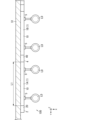
- FIG. 1 is an external view showing an example of use of a wiring duct system according to an embodiment of the present disclosure.
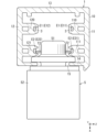
- FIG. 2 is a cross-sectional view of a wiring duct included in the wiring duct system.
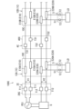
- FIG. 3 is a schematic wiring diagram of the above wiring duct system.
- FIG. 4 is a schematic wiring diagram of a wiring duct system of a comparative example.
- the wiring duct 1 according to the embodiment of the present disclosure will be described in detail with reference to the drawings.
- the wiring duct 1 described below that is, the "wiring duct”
- the wiring duct 1 described below is also called a power supply track.
- the "wiring duct” is also called a wiring duct rail.
- the embodiment and modified examples described below are merely examples of the present disclosure, and the present disclosure is not limited to the embodiment and modified examples. Even if it is not this embodiment and modified example, various modifications are possible according to the design, etc., as long as it does not deviate from the technical idea of the present disclosure.
- the following embodiments may be realized in appropriate combinations.
- FIG. 1 An overview of a wiring duct 1 and a wiring duct system 100 according to the present embodiment will be described with reference to FIGS. 1 to 3.
- FIG. 1 An overview of a wiring duct 1 and a wiring duct system 100 according to the present embodiment will be described with reference to FIGS. 1 to 3.
- FIG. 1 An overview of a wiring duct 1 and a wiring duct system 100 according to the present embodiment will be described with reference to FIGS. 1 to 3.
- the wiring duct system 100 is installed on the construction surface S1 of the facility. Although not shown in FIG. 1, it is preferable that the wiring duct system 100 is housed in a connecting member and installed on the construction surface S1 via the connecting member.
- the wiring duct system 100 has a wiring duct 1 (1A), another wiring duct (wiring duct 1 (1B)), and a power supply member 2 that supplies voltage to the wiring duct 1 from a power source PS1 (see Figure 3).
- the second conductor E2 supplies a second voltage V2, which is lower than the first voltage V1, to the load LD.
- the main body 10 holds the first conductor E1 and the second conductor E2.
- the first conductor E1 is held in the main body 10 while being covered with the insulating member 3.
- the second conductor E2 is held in the main body 10 with at least a portion of it exposed.
- the second voltage V2 is a DC voltage that is equal to or lower than a predetermined value.
- the first conductor E1 that supplies the first voltage V1 is held in the main body 10 while being covered by the insulating member 3.
- the second voltage V2 that is supplied by the exposed second conductor E2 is a DC voltage lower than the first voltage V1. Therefore, with the above configuration, the wiring duct 1 and the wiring duct system 100 can be installed in a location where a part of the user's body (e.g., a finger) may come into contact with the first conductor E1. Therefore, with the above configuration, the freedom of installation location of the wiring duct system 100 can be improved.
- the direction perpendicular to the wall surface is defined as the "front-rear direction” and the normal direction of the wall surface is defined as the "forward direction”.
- the longitudinal direction of the wiring duct 1 is defined as the "left-right direction”
- the direction perpendicular to the "front-rear direction” and "left-right direction” is defined as the "up-down direction”.
- the positive direction in the X-axis direction is defined as the "forward direction”
- the positive direction in the Y-axis direction is defined as the "left”
- the positive direction in the Z-axis direction is defined as the "upward direction”.
- the "orthogonal" direction does not mean only the strict 90° direction, but also includes directions that can be regarded as equivalent to the 90° direction in light of common technical knowledge, as long as the present embodiment achieves the intended effect.
- the wiring duct system 100 comprises a wiring duct 1 (1A), another wiring duct (wiring duct 1 (1B)), and a power supply member 2.
- the wiring duct system 100 further comprises a relay member 4 for connecting the wiring duct 1 (1A) to the other wiring duct (wiring duct 1 (1B)).
- the other wiring duct connected to the wiring duct 1 may be another wiring duct 1, or may be a wiring duct having a different configuration from the wiring duct 1.
- the wiring duct 1 comprises a main body 10, a pair of first conductors E1, a pair of second conductors E2, and a pair of insulating members 3.
- the main body 10 has an elongated shape that extends in one direction (the left-right direction in this embodiment).
- the length L1 along the left-right direction of the main body 10 is, for example, 3 m.
- the length L1 is not limited to 3 m, and may be 1 m, 1.5 m, 2 m, etc.
- the length L1 may be an integer multiple of 1 m, 1.5 m, 2 m, or 3 m. However, it is preferable that the length L1 is 6 m or less.
- the wiring duct system 100 may have multiple types of wiring ducts 1 with different lengths L1.
- the main body 10 has walls 11, 12 that face each other in the up-down direction, and walls 13, 14 that face each other in the front-rear direction.
- Wall 13 mechanically connects the rear ends of walls 11, 12.
- the main body 10 has a U-shaped cross section formed by wall 13 and walls 11, 12 that protrude forward from both ends of wall 13.
- the wall 14 of the main body 10 has an opening 15 extending in the left-right direction.
- a load LD can be connected to any position in the left-right direction of the opening 15 via a connection device 5, which will be described later.
- the main body 10 holds a pair of first conductors E1 and a pair of second conductors E2 arranged along the left-right direction.
- the pair of first conductors E1 and the pair of second conductors E2 are held in the main body 10 along the left-right direction.
- one of the pair of first conductors E1, the first conductor E11 is held by the wall portion 11.
- the other of the pair of first conductors E1, the first conductor E12 is held by the wall portion 12.
- one of the pair of first conductors E1, the first conductor E11 is held by the tip of the protrusion 110 of the wall portion 11
- the other of the pair of first conductors E12 is held by the tip of the protrusion 120 of the wall portion 12.
- the pair of first conductors E1 are covered by a pair of insulating members 3 and are held by the protrusions 110 and 120, respectively.
- the pair of insulating members 3 are made of an insulating material such as synthetic resin.
- the pair of insulating members 3 are formed integrally with the protrusions 110 and 120, respectively.
- the pair of insulating members 3 may also be formed separately from the protrusions 110 and 120, respectively.
- a first voltage V1 is supplied from a power source PS1 to the pair of first conductors E1 via a power supply member 2.
- the power source PS1 that supplies power to the pair of first conductors E1 is a single-phase two-wire commercial AC power source.
- the first voltage V1 is an AC voltage.
- the power source PS1 may be a single-phase three-wire commercial AC power source, or a three-phase three-wire commercial AC power source.
- the first voltage V1 is an AC voltage with a power source frequency of 50 Hz or 60 Hz and an effective value of 100 V.
- the first voltage V1 may also be an AC voltage with an effective value of 200 V.
- the wiring duct system 100 can be installed not only on a construction surface S1 (such as a ceiling) that the user's body cannot reach, but also on a construction surface S1 such as a wall or bottom where the user's body may come into contact with the first conductor E1.
- the wiring duct system 100 can also be installed in a place on a piece of furniture such as a desk that the user's body can reach.
- the power supply member 2 is a so-called feed-in cap, and as shown in FIG. 1, is connected to the left-right end (e.g., the left end) of the main body 10.
- the power supply member 2 has a main body 20 and a pair of connection terminals T1 held by the main body 20.
- a pair of electric wires connected to a power source PS1 is connected to each of the pair of connection terminals T1.
- a pair of first conductors E1 is also connected to each of the pair of connection terminals T1.
- a first voltage V1 is supplied from the power source PS1 to the pair of first conductors E1 via the power supply member 2.
- the power supply member 2 supplies the first voltage V1 from the power source PS1 to the pair of first conductors E1.
- One second conductor E21 of the pair of second conductors E2 is held by the wall portion 11 as shown in FIG. 2.
- the other second conductor E22 of the pair of second conductors E2 is held by the wall portion 12.
- one second conductor E21 of the pair of second conductors E2 is held by the tip of a protrusion 111 of the wall portion 11, and the other second conductor E22 is held by the tip of a protrusion 121 of the wall portion 12.
- the protrusions 111 and 121 are provided below the protrusions 110 and 120.
- the pair of second conductors E2 is located in front of the pair of first conductors E1.
- the pair of second conductors E2 are held by the protrusions 111 and 121, respectively, with at least a portion of them exposed. Specifically, the second conductor E2 held by the protrusion 111 is exposed downward. Furthermore, the second conductor E2 held by the protrusion 121 is exposed upward.
Landscapes
- Engineering & Computer Science (AREA)
- Architecture (AREA)
- Civil Engineering (AREA)
- Structural Engineering (AREA)
- Details Of Indoor Wiring (AREA)
Abstract
Priority Applications (3)
| Application Number | Priority Date | Filing Date | Title |
|---|---|---|---|
| JP2025529531A JPWO2025004630A1 (fr) | 2023-06-26 | 2024-05-22 | |
| CN202480037430.2A CN121241491A (zh) | 2023-06-26 | 2024-05-22 | 配线槽和配线槽系统 |
| EP24831501.2A EP4734298A1 (fr) | 2023-06-26 | 2024-05-22 | Conduit de câblage et système de conduit de câblage |
Applications Claiming Priority (2)
| Application Number | Priority Date | Filing Date | Title |
|---|---|---|---|
| JP2023-104491 | 2023-06-26 | ||
| JP2023104491 | 2023-06-26 |
Publications (1)
| Publication Number | Publication Date |
|---|---|
| WO2025004630A1 true WO2025004630A1 (fr) | 2025-01-02 |
Family
ID=93938102
Family Applications (1)
| Application Number | Title | Priority Date | Filing Date |
|---|---|---|---|
| PCT/JP2024/018874 Ceased WO2025004630A1 (fr) | 2023-06-26 | 2024-05-22 | Conduit de câblage et système de conduit de câblage |
Country Status (4)
| Country | Link |
|---|---|
| EP (1) | EP4734298A1 (fr) |
| JP (1) | JPWO2025004630A1 (fr) |
| CN (1) | CN121241491A (fr) |
| WO (1) | WO2025004630A1 (fr) |
Citations (3)
| Publication number | Priority date | Publication date | Assignee | Title |
|---|---|---|---|---|
| JPS5187296U (fr) * | 1975-01-06 | 1976-07-13 | ||
| JPS60189973U (ja) * | 1984-05-25 | 1985-12-16 | 松下電工株式会社 | 配線ダクト用給電装置 |
| JP2012009258A (ja) | 2010-06-24 | 2012-01-12 | Panasonic Electric Works Co Ltd | 配線ダクト、配線ダクト接続部材、配線ダクト用の電気機器および配線ダクトを用いた配電システム |
-
2024
- 2024-05-22 WO PCT/JP2024/018874 patent/WO2025004630A1/fr not_active Ceased
- 2024-05-22 CN CN202480037430.2A patent/CN121241491A/zh active Pending
- 2024-05-22 JP JP2025529531A patent/JPWO2025004630A1/ja active Pending
- 2024-05-22 EP EP24831501.2A patent/EP4734298A1/fr active Pending
Patent Citations (3)
| Publication number | Priority date | Publication date | Assignee | Title |
|---|---|---|---|---|
| JPS5187296U (fr) * | 1975-01-06 | 1976-07-13 | ||
| JPS60189973U (ja) * | 1984-05-25 | 1985-12-16 | 松下電工株式会社 | 配線ダクト用給電装置 |
| JP2012009258A (ja) | 2010-06-24 | 2012-01-12 | Panasonic Electric Works Co Ltd | 配線ダクト、配線ダクト接続部材、配線ダクト用の電気機器および配線ダクトを用いた配電システム |
Also Published As
| Publication number | Publication date |
|---|---|
| JPWO2025004630A1 (fr) | 2025-01-02 |
| CN121241491A (zh) | 2025-12-30 |
| EP4734298A1 (fr) | 2026-04-29 |
Similar Documents
| Publication | Publication Date | Title |
|---|---|---|
| AU2007313159B2 (en) | Electrified ceiling framework connectors | |
| US9469988B2 (en) | Grid framework accessories | |
| US8770993B2 (en) | Connector assembly with polarity correction/protection | |
| US8469728B1 (en) | Polarity protection for electrified grid and mating connector | |
| US20120184132A1 (en) | Direct current outlet | |
| MX2014005043A (es) | Receptaculo electrico de bajo voltaje para sistemas electricos modulares. | |
| US6666713B1 (en) | Ganged receptacle fixture apparatus | |
| CN114556716B (zh) | 承载轨和具有承载轨的承载轨系统 | |
| EP4734298A1 (fr) | Conduit de câblage et système de conduit de câblage | |
| US20200218214A1 (en) | Multiple location electrical control system with synchronizing buttons | |
| CN117239495A (zh) | 一种轨道插座及轨道插座的配电系统 | |
| JPH09247828A (ja) | 配線構造 | |
| JP3458672B2 (ja) | 配線ダクト | |
| JP2008251510A (ja) | 配線システム | |
| CN219535561U (zh) | 一种天花板吊顶走线管组件 | |
| WO2021086853A1 (fr) | Système électriques pour bâtiments | |
| AU2014101063B4 (en) | Power charger | |
| JP7390572B2 (ja) | 制御装置及び電力変換システム | |
| AU2016203455B2 (en) | Power charger | |
| JP2024069052A (ja) | 配線ダクトシステム及び支持部材 | |
| JP3304127B2 (ja) | スイッチ | |
| CN118263814A (zh) | 一种面板盒及电线暗盒 | |
| JP2557683Y2 (ja) | 中継端子を有するスイッチを備えた照明器具及びコンセントへの結線構造 | |
| KR20240009235A (ko) | 전기차 충전기 | |
| JP3125998U (ja) | 屋内用照明装置 |
Legal Events
| Date | Code | Title | Description |
|---|---|---|---|
| 121 | Ep: the epo has been informed by wipo that ep was designated in this application |
Ref document number: 24831501 Country of ref document: EP Kind code of ref document: A1 |
|
| ENP | Entry into the national phase |
Ref document number: 2025529531 Country of ref document: JP Kind code of ref document: A |
|
| WWE | Wipo information: entry into national phase |
Ref document number: 2025529531 Country of ref document: JP |
|
| ENP | Entry into the national phase |
Ref document number: 2024831501 Country of ref document: EP Effective date: 20260126 |
|
| WWE | Wipo information: entry into national phase |
Ref document number: 2024831501 Country of ref document: EP |
|
| NENP | Non-entry into the national phase |
Ref country code: DE |
|
| ENP | Entry into the national phase |
Ref document number: 2024831501 Country of ref document: EP Effective date: 20260126 |
|
| ENP | Entry into the national phase |
Ref document number: 2024831501 Country of ref document: EP Effective date: 20260126 |
|
| WWP | Wipo information: published in national office |
Ref document number: 2024831501 Country of ref document: EP |