WO2025004792A1 - Dispositif de prélèvement de sang - Google Patents
Dispositif de prélèvement de sang Download PDFInfo
- Publication number
- WO2025004792A1 WO2025004792A1 PCT/JP2024/021211 JP2024021211W WO2025004792A1 WO 2025004792 A1 WO2025004792 A1 WO 2025004792A1 JP 2024021211 W JP2024021211 W JP 2024021211W WO 2025004792 A1 WO2025004792 A1 WO 2025004792A1
- Authority
- WO
- WIPO (PCT)
- Prior art keywords
- finger
- puncture
- puncturing
- module
- blood collection
- Prior art date
- Legal status (The legal status is an assumption and is not a legal conclusion. Google has not performed a legal analysis and makes no representation as to the accuracy of the status listed.)
- Pending
Links
Images


Classifications
-
- A—HUMAN NECESSITIES
- A61—MEDICAL OR VETERINARY SCIENCE; HYGIENE
- A61B—DIAGNOSIS; SURGERY; IDENTIFICATION
- A61B5/00—Measuring for diagnostic purposes; Identification of persons
- A61B5/15—Devices for taking samples of blood
- A61B5/151—Devices specially adapted for taking samples of capillary blood, e.g. by lancets, needles or blades
Definitions
- the present invention relates to a blood sampling device that automatically samples blood from the subject's fingers.
- blood collection devices have been developed that automatically collect blood from the subject's fingers.
- the subject's fingers are placed in a designated finger placement area, a needle is automatically inserted into the finger, and blood that flows out from the puncture site is collected in a blood collection tube.
- Patent Document 1 describes a blood collection device that automatically collects blood from the subject's fingers.
- This blood collection device is configured so that a perforator holder containing a puncture needle is raised from below the finger, causing the puncture needle to puncture the finger.
- the perforator holder is pushed by the push rod part, the perforator comes into contact with the finger, and the perforator punctures the finger when it receives a certain amount of load.
- Patent Document 2 describes a blood testing device that punctures a finger with laser light to supply blood to a blood sensor.
- This blood testing device is equipped with a finger restriction member that restricts the position of the finger. By restricting the position of the finger with the finger restriction member, it becomes easier to store blood flowing out of the finger in the storage section.
- Patent Document 3 describes a bodily fluid collection aid used when collecting bodily fluids from a puncture site on the surface of a living body. This bodily fluid collection aid is configured to adjust the puncture depth of the puncture needle into the fingertip with a dial-type adjustment unit. The puncture depth of the puncture needle into the fingertip is set according to the individual differences of the blood collector and the puncture site.
- the needle When collecting blood from the subject's fingers in an automatic blood collection device, the needle must be inserted just deep enough into the finger. If the needle is inserted too far, the vein may not be reached or the required amount of blood may not be collected, so it is necessary to ensure a sufficient puncture depth. On the other hand, if the needle is inserted too far, it may cause severe pain, so a puncture deeper than necessary should be avoided.
- the puncture unit to which the puncture needle is attached is automatically controlled to move from an initial position to a position where it will puncture the recipient's finger.
- a function is required to ensure an appropriate puncture depth in order to puncture the finger without over or underdoing it.
- Some blood collection devices automatically collect blood by inserting a puncture needle into the subject's finger and automatically collecting the blood that flows down from the puncture site into a blood collection tube.
- the finger holder may be provided with a window-like opening that penetrates from top to bottom. The subject's finger is placed on the finger holder so that the ventral side is exposed downward through the opening.
- the puncture part to which the puncture needle is attached is raised from below the finger placed on the finger holder to puncture the puncture needle. Therefore, the puncture part is driven to rise so that the tip of the puncture needle is within a predetermined puncture depth range.
- Patent Document 1 simply pushes up the perforator holder with a push rod part, so there is room for improvement in terms of this type of problem of individual variability.
- Patent Document 2 uses a laser to perform the puncture, and does not take measures to address this type of problem of individual variability.
- Patent Document 3 uses a dial-type adjustment, which makes it difficult to apply to a blood collection device that automatically collects blood.
- Possible methods for adjusting the puncture depth include sensing the distance to the blood vessels of each individual's fingers, or measuring the fingers of each individual person beforehand. Based on these measurement results, it is possible to control the puncture part to which the puncture needle is attached to a target movement amount according to the measurement results. However, such methods have the problem of increasing the effort required for blood collection and the cost of the equipment.
- the present invention aims to provide a blood sampling device that can efficiently and inexpensively puncture the subject's fingers to an appropriate depth, regardless of the characteristics of the subject's fingers.
- the blood collection device of the present invention is a blood collection device that includes a puncture unit having a puncture needle, a puncture mechanism that moves the puncture unit to puncture the puncture needle into a finger of a person to be blood-collected, and a control unit that controls the operation of the puncture mechanism, where the puncture mechanism raises the puncture unit from below the finger to puncture the puncture needle into the finger, and the control unit controls the operation of the puncture mechanism to drive the puncture unit to rise and fall, and stops the raising of the puncture unit by the puncture mechanism upon detection of contact of the puncture unit with the finger.
- the present invention provides a blood sampling device that can efficiently and at low cost puncture the subject's fingers to the appropriate depth, regardless of the characteristics of the subject's fingers.
- FIG. 1 is an external view of a blood sampling device according to an embodiment of the present invention.
- FIG. 2 is a cross-sectional view showing a schematic example of a puncture mechanism of a blood sampling device according to an embodiment of the present invention.
- 11 is a cross-sectional view illustrating an individual difference in the distance between the finger of a blood sample recipient and a puncture needle.
- 5A to 5C are cross-sectional views illustrating the operation of the detection mechanism.
- 5A to 5C are cross-sectional views illustrating the operation of the detection mechanism.
- 13A and 13B are diagrams showing application examples of a puncture mechanism and a detection mechanism.
- 13A and 13B are diagrams showing application examples of a puncture mechanism and a detection mechanism.
- 13A and 13B are diagrams showing application examples of a puncture mechanism and a detection mechanism.
- 13A and 13B are diagrams showing application examples of a puncture mechanism and a detection mechanism.
- 13A and 13B are diagrams showing application examples of
- FIG. 1 is an external view of a blood sampling device according to an embodiment of the present invention.
- FIG. 1 shows a finger blood sampling device that automatically samples blood from the subject's finger.
- the symbol P in FIG. 1 is an enlarged partial view showing the area around the finger placement area of the blood sampling device as viewed from below.
- the blood collection device 1 includes a housing 10, a turntable 11, a number of holders 110 in which blood collection tubes are placed, a number of modules 120 to which a puncture device, hemostatic material, etc. are attached, a cuff mechanism 130, a rotation drive mechanism (not shown) that rotates the turntable 11, a lift drive mechanism (not shown) that raises and lowers the holders 110 and modules 120, a pressure adjustment mechanism (not shown) that drives the cuff mechanism 130, etc.
- the housing 10 is formed from multiple structural materials, decorative panels, etc. Inside the housing 10, a turntable 11, a rotation drive mechanism, an elevation drive mechanism, a pressure adjustment mechanism, etc. are built in. On the top surface of the housing 10, there is a hand placement area where the hand of the person to be blood-collected is placed, and a circular opening adjacent to the hand placement area. The turntable 11 is located below the opening.
- a cuff mechanism 130 and a finger rest area 131 are provided on the opening side of the hand rest area.
- the cuff mechanism 130 is installed above the finger rest area 131 so as to surround the finger 134 of the person to be blood-collected, which is placed on the finger rest area 131.
- a disposable finger rest part 132 is attached to the finger rest area 131.
- a blood collection window 133 which is a through-hole, opens in the center of the finger rest part 132.
- the finger 134 of the person to be blood-collected is placed on the blood collection window 133 of the finger rest part 132.
- the cuff mechanism 130 is a mechanism that tightens the periphery of the subject's finger (the subject's hand) 134.
- a cuff is placed on the finger placement area 131 so as to surround the subject's finger 134 placed there.
- the cuff is, for example, in the form of a flexible bag, and is connected to a valve and a pump via a tube.
- the valve and pump constitute a pressure adjustment mechanism that drives the cuff mechanism 130.
- the internal pressure of the cuff is controlled by the pressure adjustment mechanism, thereby adjusting the tightening pressure on the subject's finger 134.
- the turntable 11 is generally disk-shaped and is supported inside the housing 10 with its main surfaces facing up and down.
- the turntable 11 is provided with a number of portions for holding the holders 110 and various modules 120.
- a number of holding holes are provided that penetrate the turntable 11 from top to bottom.
- the holders 110 and modules 120 are held by being inserted from top to bottom into the holding holes.
- the portions for holding the holders 110 and modules 120 are regularly spaced apart along the circumferential direction of the turntable 11.
- the holder 110 is where the blood collection tubes are placed, and various types of blood collection tubes, such as blood collection tubes for blood count tests and blood collection tubes for biochemistry and immunological tests, are placed in it. Blood collection tubes of a specified size and outer tubes that contain blood collection tubes can be placed in the holder 110. The outer tubes are used for purposes such as adjusting the size of the object to be placed in relation to the placement location of the blood collection tube.
- the holder 110 and the module 120 can be attached and detached to the turntable 11.
- the holder 110 and the module 120 are formed with a flange-shaped portion whose diameter is larger than the inner diameter of the holding hole of the turntable 11.
- the holder 110 and the module 120 can be inserted into the holding hole and the flange-shaped portion is supported from below, so that the holder 110 and the module 120 can be held in a state in which they can be raised and lowered within the holding hole.
- modules 120 can be attached as module 120, such as a module for puncturing, a module for stopping bleeding, etc.
- a puncture device is attached to the module for puncturing.
- the puncture device has a built-in puncture needle (lancet).
- a hemostatic material such as gauze or a protective material such as a bandage is attached to the module for stopping bleeding.
- the puncture needle When the lancing device is pressed against the subject's finger, the puncture needle extends and punctures the subject's finger.
- a hemostatic material such as gauze is pressed against the puncture site on the subject to stop the bleeding by absorbing blood that has bled from the puncture site.
- a protective material such as a bandage is pressed against the puncture site on the subject and applied to cover the puncture site to seal the puncture site, stop the bleeding, and protect it.
- the bandage is attached to the module 120 with the adhesive side facing upwards.
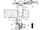
- FIG. 2 is a cross-sectional view showing an example of a puncture mechanism of a blood sampling device according to an embodiment of the present invention.
- FIG. 2 shows a cross-sectional structure of a turntable 11 and its surroundings installed inside the blood sampling device 1.
- a turntable 11 As shown in FIG. 2, in blood sampling device 1, below the opening of housing 10, a turntable 11, lifting member 12, base member 20, movable support member 30, etc. are built in.
- a compression coil spring 21 and a detection sensor 22 are attached to the base member 20.
- a movable support member 30 is supported on the upper end side of the compression coil spring 21.
- a detection target portion 31 that is detected by the detection sensor 22 is formed on the movable support member 30.
- the upper end side of the movable support member 30 is a portion that pushes up the puncture module 120 and the like that are installed on the turntable 11.
- a shaft (not shown) is connected to the center of the turntable 11.
- the other end of the shaft is connected to the output shaft of a motor via a power transmission mechanism.
- the power transmission mechanism transmits the rotational motion of the motor to the shaft by a specified mechanical mechanism.
- the turntable 11 can rotate in both clockwise and counterclockwise directions with the shaft as the rotation axis by the rotation of the shaft by the motor.
- the turntable 11 is controlled to rotate at a predetermined step angle around the shaft as the axis of rotation in accordance with the blood collection operation or treatment operation.
- the holder 110 and the module 120 are each transported sequentially to the blood collection position where the finger placement area 131 is formed by the rotation of the turntable 11.
- the puncture needle is inserted by the puncture module 120, the hemostasis module 120 stops the bleeding using gauze, and the hemostasis module 120 applies a bandage, in that order.
- the subject's finger 134 is compressed by the cuff 136, and then punctured with the puncture needle by the puncture module 120.
- the blood that flows out from the puncture site is collected in a blood collection tube that has been moved to the blood collection position on the turntable 11.
- the puncture module 120 is shown transported to the blood collection position.
- a puncture device 122 incorporating a puncture needle 121 is attached to the puncture module 120.
- the puncture module 120 constitutes a removable puncture section that has the puncture needle 121. By pushing up the puncture module 120, which is the puncture section, the puncture needle punctures the finger 134 of the person to be blood-collected.
- the operation of the puncturing module 120 is driven by a puncturing mechanism.
- the puncturing mechanism moves the puncturing module 120, which is the puncturing part, to puncture the puncturing needle 121 into the finger 134 of the person to be drawn.
- the puncturing mechanism raises the puncturing module 120, which is the puncturing part, from below the finger 134 of the person to be drawn, to puncture the puncturing needle 121 into the finger 134 of the person to be drawn.
- the puncturing mechanism is composed of the lifting member 12, base member 20, movable support member 30, and a lifting drive mechanism that lifts and lowers these members up and down.
- the lifting member 12 is positioned below the blood collection position.
- the lifting member 12 is supported by a lifting drive mechanism (not shown) so that it can move up and down freely.
- the lifting drive mechanism is composed of a motor and a power transmission mechanism.
- the power transmission mechanism connects the output shaft of the motor and the lifting member 12 via a specific mechanical mechanism.
- the rotational motion of the motor is converted into vertical linear motion by the power transmission mechanism.
- the lifting member 12 is driven to move up and down by such a mechanism.
- a base member 20 is supported on the lifting member 12.
- the base member 20 connects the lifting member 12 and the movable support member 30, and supports the compression coil spring 21 and the detection sensor 22.
- the base member 20 supports the compression coil spring 21 and the detection sensor 22 at a predetermined relative position to the lifting member 12.
- the base member 20, the compression coil spring 21, the detection sensor 22, and the movable support member 30 can move up and down integrally with the lifting member 12.
- the movable support member 30 rises together with the lifting member 12, and pushes up from below the holder 110 and the module 120 that have been transported to the blood collection position.
- the puncture module 120 which is the puncture section, comes into contact with the subject's finger 134, and the puncture needle punctures the subject's finger 134.
- the blood collection tube held by the holder 110 and the module 120 to which the hemostatic material and protective material are attached are pressed against the subject's finger 134, and procedures such as blood collection and hemostasis are performed.
- the blood sampling device 1 is equipped with a control unit (not shown) that controls the operation of the puncturing mechanism.
- the control unit controls the operation of the puncturing mechanism, which is composed of a lifting drive mechanism, etc., and drives the raising and lowering of the puncturing module 120, which is the puncturing part, relative to the finger placement area 131.
- the control unit is composed of a controller such as a PLC (Programmable Logic Controller).
- the raising of the puncturing module 120, which is the puncturing part, relative to the finger 134 of the person to be blood sampled, is driven by a control input from the control unit.
- the detection mechanism is structured to utilize the elastic contraction of the compression coil spring 21, and is configured to detect the puncture using a mechanical mechanism.
- the detection target 31 is formed in the middle of the movable support member 30 in the vertical direction.
- a detection mechanism detects contact of the puncturing module 120, which is the puncturing part, with the subject's finger 134, and adjusts the puncturing depth into the subject's finger 134 within an appropriate range.
- the puncturing depth By adjusting the puncturing depth within an appropriate range, it becomes possible to perform puncturing with minimal over- or under-doing, even if there are individual differences in the subject's finger 134. This makes it possible to stably ensure the required amount of blood to be collected, while avoiding puncturing pain caused by the puncturing needle 121.
- Figure 3 is a cross-sectional view illustrating the individual differences in the distance between the subject's finger and the puncture needle.
- Figure 3 shows a schematic cross-sectional structure around the turntable 11 installed inside the blood sampling device 1 with some components omitted.
- the solid line indicating the subject's finger 134 shows an example of the finger position when the finger is of standard thickness.
- the dashed line shows an example of the finger position when the finger is thicker than standard.
- the dotted line shows an example of the finger position when the finger is thinner than standard.
- the symbol D indicates the distance between the finger placement area 131 and the reference position on the puncture module 120 stopped at the initial position.
- the reference position is a position that serves as a reference for controlling the amount of movement, such as the height of the top end of the module 120.
- the symbol D- A indicates the distance between a finger of standard thickness and the reference position on the puncture module 120 in the initial position
- the symbol D- S indicates the distance between a finger of thicker than standard thickness and the reference position on the puncture module 120 in the initial position
- the symbol D- L indicates the distance between a finger of thinner than standard thickness and the reference position on the puncture module 120 in the initial position.
- the distance between the subject's finger 134 placed in the finger holder 131 of the blood sampling device 1 and the puncture needle 121 of the puncture module 120 in the initial position may differ for each subject due to individual differences in the subject's finger 134. Therefore, in order to adjust the puncture depth of the subject's finger 134 within an appropriate range, it is necessary to appropriately control the amount of upward movement of the puncture module 120, which is the puncture part having the puncture needle 121, relative to the subject's finger 134.
- the puncture device 122 has a system in which the puncture needle 121 is protruded by a spring.
- the puncture needle 121 is fixed to a holding hub built into the puncture device 122.
- a drive spring is built into the lower part of the puncture needle 121 and the holding hub.
- a retraction spring is built into the upper part of the puncture needle 121.
- the holding hub is structured so that it begins to deform when the puncture device 122 comes into contact with the subject's finger 134, and releases the puncture needle 121 when a predetermined deformation occurs.
- the puncture depth must be adjusted mainly by the amount of upward movement of the puncture module 120, which is the puncture section.
- the puncture module 120 When raising the puncture module 120, at least an external force is required to activate the holding hub and drive spring, and a minimum external force is required due to contact between the puncture device 122 attached to the puncture module 120 and the subject's finger 134.
- the thickness and other characteristics of the subject's finger 134 may vary from person to person. Furthermore, the way in which the subject's finger 134 is placed on the finger holder 131 of the blood sampling device 1 and the response to pressure from the cuff 136 may differ from person to person. When the subject's finger 134 is placed on the finger holder 131 or is compressed by the cuff 136, there may be individual differences in the distance from the surface of the finger pad to the blood vessels, the degree of expansion when blood is stagnant, etc.
- the distance D S between the subject's finger 134 and the reference position on the puncturing module 120 in the initial position is shorter than the standard distance D A.
- the puncturing needle 121 may not reach the blood vessel, or the puncturing needle 121 may not damage the blood vessel wall sufficiently, making it impossible to ensure the required amount of blood to be collected.
- the distance D L between the subject's finger 134 and the reference position on the puncturing module 120 in the initial position becomes longer than the standard distance D A.
- the puncturing depth is not appropriately adjusted, the subject's finger 134 is likely to be punctured excessively. This may cause severe puncturing pain due to the puncture of the puncture needle 121, or the puncture site may be difficult to heal.
- the amount of movement by which the puncturing module 120 is raised from the initial position toward the subject's finger 134 is controlled to a predetermined amount of movement that is set in advance for multiple subjects whose fingers vary in size and thickness.
- the amount of movement by which the puncturing module 120 is raised from the initial position toward the subject's finger 134 is set to a movement amount (D+ ⁇ ) that is a predetermined amount ⁇ greater than the distance D between the finger placement area 131 and the reference position on the puncturing module 120 in the initial position.
- a target movement amount (D+ ⁇ ) with a margin of the predetermined amount ⁇ added is preset in the control unit as a control target value for the puncturing mechanism.
- the ascent of the puncturing module 120 relative to the subject's finger 134 is stopped upon detection of contact of the puncturing module 120 with the subject's finger 134.
- the control unit controls the lifting drive mechanism that lifts the puncturing module 120, which is the puncturing unit, to a preset target movement amount (D+ ⁇ ), but stops the ascent of the puncturing module 120 upon detection of contact of the puncturing module 120 with the subject's finger 134.
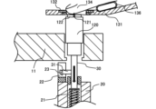
- FIGS. 4A and 4B are cross-sectional views explaining the operation of the detection mechanism.
- the operation of the detection mechanism that detects contact of the puncturing module 120 with the subject's finger 134 is shown diagrammatically with some components around the turntable 11 omitted.
- FIG. 4A shows the state before the puncturing module 120 comes into contact with the subject's finger 134.
- FIG. 4B shows the state after the puncturing module 120 has come into contact with the subject's finger 134.
- the contact of the puncture module 120 with the subject's finger 134 is detected by the compression coil spring 21, which is an elastic member constituting the detection mechanism, the detection sensor 22, and the detection target 31.
- the detection target 31 is a non-light-transmitting member that can be formed into an appropriate shape such as a plate or rod.
- the compression coil spring 21 elastically supports the movable support member 30 so that it can rise and fall freely relative to the base member 20.
- the compression coil spring 21 is arranged so that the direction of expansion and contraction is parallel to the vertical direction.
- the lower end side of the compression coil spring 21 is fixed in a relative position to the lifting member 21 side.
- the upper end side of the compression coil spring 21 is fixed to the lower end side of the movable support member 30.
- the compression coil spring 21 biases the movable support member 30 upward, and when the movable support member 30 receives a downward force, it elastically contracts in the vertical direction.
- the compression coil spring 21 is set to a spring constant such that, in its initial elastic displacement, it balances with the load caused by the weight of the movable support member 30, but contracts when the puncture module 120 receives an external force from the subject's finger 134. If the puncture device 122 is protruded by a drive spring, the compression coil spring 21 must be set to a spring constant such that it contracts when an external force greater than the external force that activates the retaining hub or drive spring is applied.
- the detection sensor 22 detects that the detection target 31 has moved to a specified position.
- the detection sensor 22 has a fixed position relative to the base member 20 and the lifting member 12.
- the detection sensor 22 is positioned near the movable support member 30 and below the detection target 31, which moves up and down.
- the detection sensor 22 can be supported on the upper part of the base member 20, etc.
- a photointerrupter is provided as the detection sensor 22.
- the photointerrupter has a light-emitting element and a light-receiving element as the detection unit 23 that detects the detection target 31.
- the light-emitting element and the light-receiving element are arranged on the lower side of the upper and lower tracks of the detection target 31 so as to face each other at a predetermined height.
- a gap is formed between the light-emitting element and the light-receiving element, through which the detection target 31 formed on the movable support member 30 can move forward and backward.
- the light-emitting element of the photointerrupter is formed of a light-emitting diode that emits infrared light or the like.
- the light-receiving element is formed of a photodiode, phototransistor, or the like that detects the light emitted by the light-emitting element.
- the detection sensor 22 can detect that the detection target 31 has descended to a predetermined height when the movable support member 30 receives a downward force and the compression coil spring 21 contracts. Therefore, by detecting the detection target 31, it can indirectly detect that the puncturing module 120 has come into contact with the subject's finger 134. Since the amount of movement of the puncturing module 120 can be limited without sensing the distance with an optical sensor or the like, the cost of the equipment can be reduced compared to a method of sensing the distance to the blood vessels of the finger.
- the base member 20 and the lifting member 12 are driven to rise.
- the movable support member 30 supported by the base member 20 also rises, and the puncture module 120, which is the puncture section, is pushed up to a height where it comes into contact with the finger 134 of the person to be sampled that is placed on the finger holder 131.
- the compression coil spring 21 is in an extended state, and the relative position of the movable support member 30 with respect to the base member 20 is on the upper side.
- the detection target portion 31 formed on the movable support member 30 is located above the detection portion 23, and is not detected by the detection sensor 22.
- the puncture needle 121 protrudes from the puncture device 122 and punctures the subject's finger 134.
- the puncture needle 121 punctures the subject's finger 134 while the movable support member 30 is biased in an upward direction by the compression coil spring 21. Therefore, if the puncture device 122 is protruded by a drive spring, the external force that activates the retaining hub and drive spring can be easily secured.
- the puncturing module 120 when the puncturing module 120 comes into contact with the subject's finger 134, it receives a downward external force from the subject's finger 134. This external force stops the puncturing module 120 and the movable support member 30 from rising, and the compression coil spring 21 contracts. After the puncturing portion comes into contact with the subject's finger 134, the compression coil spring 21 becomes compressed, and the relative position of the movable support member 30 to the base member 20 moves downward. The detection target portion 31 formed on the movable support member 30 descends to the height of the detection portion 23 and is detected by the detection sensor 22.
- Such a detection mechanism detects the contact of the puncturing module 120, which is the puncturing part, with the subject's finger 134 while the base member 20 and the lifting member 12 are being driven to rise.
- a detection signal is transmitted from the detection sensor 22 to the control unit, and the control unit stops the lifting of the lifting member 12. By stopping the lifting of the lifting member 12, excessive puncturing of the subject's finger 134 can be prevented.
- the amount of movement of the puncturing module 120 from the initial position toward the subject's finger 134 can be controlled to a preset constant amount of movement (D+ ⁇ ) for a plurality of subjects whose fingers vary in size, thickness, etc.
- the predetermined amount ⁇ is set to a length that makes the amount of movement (D+ ⁇ ) longer than the standard distance D A so that insufficient puncturing due to individual differences does not occur even when the subject's finger 134 is thin. For example, a margin longer than the difference between the distance D L corresponding to a predetermined standard deviation and the standard distance D A can be set.
- one method of adjusting the puncture depth is to control the amount of movement of the puncture needle relative to the subject's finger to a target amount of movement that matches the actual measurement results.
- Measurements for setting the target amount of movement include measuring the distance between the puncture needle and the blood vessels in the subject's finger for each individual using a distance measuring sensor, or manually measuring the size of the subject's finger in advance for each individual.
- the contact of the puncturing module 120, which is the puncturing part, with the subject's finger 134 is detected by a detection mechanism using a mechanical mechanism, so that the puncturing depth of the subject's finger 134 can be adjusted efficiently and at low cost within a range that is neither too deep nor too deep.
- a target movement amount (D+ ⁇ ) with a predetermined margin of ⁇ added is set in advance, and the movement of the puncturing part is stopped when the contact of the puncturing module 120, which is the puncturing part, with the subject's finger 134 is detected.
- the required amount of blood can be stably secured while avoiding puncture pain caused by the puncturing needle 121. Since appropriate blood collection can be automatically performed, a blood collection device 1 that is highly reliable for automatically collecting blood from the subject's finger can be obtained.
- the contact of the puncturing module 120 (the puncturing part) with the subject's finger 134 is detected by detecting the descent of the movable support member 30 against the force of the compression coil spring 21, which is an action caused by the puncturing module 120 (the puncturing part) coming into contact with the finger. Therefore, the contact of the puncturing module 120 with the subject's finger 134 can be detected using a mechanical mechanism by adjusting the spring constant of the compression coil spring 21.
- the descent of the movable support member 30 is detected by the detection target 31, which rises and falls together with the movable support member 30 relative to the base member 20, and the detection sensor 22, which detects that the detection target 31 has moved to a specified position. This makes it possible to detect the operation that utilizes the mechanical mechanism of the compression coil spring 21 with equipment that is less expensive than optical displacement sensors, etc.
- a photointerrupter is provided as the detection sensor 22, but the detection sensor 22 may also be a mechanical switch such as a microswitch, or a non-contact proximity sensor that utilizes eddy current, magnetism, electromagnetic induction, etc. These detection sensors 22 can be used to detect the detection target part 31 that has descended against the force of the compression coil spring 21.
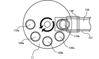
- FIGS. 5A and 5B are diagrams showing an example of application of the puncture mechanism and detection mechanism.
- FIG. 5A and FIG. 5B an example of application of the puncture mechanism and detection mechanism to a turntable 11 is shown diagrammatically with some components around the turntable 11 omitted.
- FIG. 5A is a plan view of the periphery of the turntable 11 as viewed from above.
- FIG. 5B is a partial cross-sectional view of the periphery of the turntable 11 as viewed from the side.
- the blood collection device 1 can be equipped with multiple holders 110 for holding blood collection tubes and multiple modules 120.
- the puncture mechanism and detection mechanism can also be used to adjust the amount of movement relative to the subject's finger 134 during blood collection operations using the holders 110 performed on the turntable 11, and during treatment operations using modules 120 other than the puncture module 120.
- the holders 110 for holding blood collection tubes include a first holder 110a for holding a first blood collection tube and a second holder 110b for holding a second blood collection tube, which are installed on the turntable 11.
- these blood collection tubes for example, blood collection tubes coated with an anticoagulant for blood count tests, blood collection tubes containing a separating agent for biochemistry and immunological tests, etc. can be installed.
- the modules 120 are mounted on the turntable 11 and include a puncture module 120a which is the puncture section, a hemostasis module 120b which holds a protective material such as a bandage, and a hemostasis module 120c which holds a hemostatic material such as gauze.
- the puncturing mechanism When adjusting the amount of movement relative to the subject's finger 134 during a blood sampling operation using the holder 110 or a treatment operation using a module 120 other than the puncturing module 120, the puncturing mechanism functions as a moving mechanism that moves the holder 110 or module 120 to press the blood collection tube, hemostatic material, or protective material against the subject's finger.
- the moving mechanism is composed of the lifting member 12, base member 20, movable support member 30, and a lifting drive mechanism that raises and lowers these members up and down.
- the operation of the moving mechanism composed of the lifting drive mechanism is controlled by a control unit composed of a controller.
- the holder 110 and the module 120 are transported sequentially to the blood collection position where the finger rest 131 is installed by the rotation of the turntable 11, and then are driven to rise by being pushed up by the movable support member 30.
- the blood collection tube is pressed against the subject's finger 134, and blood flowing out from the puncture site is collected.
- the protective material and hemostatic material are pressed against the subject's finger 134, and blood flowing out from the puncture site is stopped.
- the holder 110 and the module 120 may have different heights.
- the symbol d1 indicates the distance between the finger rest 131 and the reference position on the puncture module 120a in the initial position
- the symbol d2 indicates the distance between the finger rest 131 and the reference position on the blood collection tube placed on the holder 110a in the initial position
- the symbol d3 indicates the distance between the finger rest 131 and the reference position on the hemostasis module 120b in the initial position.
- these distances have a relationship of d1 ⁇ d2 ⁇ d3 .
- the amount of movement of the puncturing module 120 can be controlled to be a preset target amount of movement (D+ ⁇ ).
- the amount of movement of the holder 110 and modules 120 other than the puncturing module 120, which is the puncturing part can be set to match the distance between the subject's finger 134 and the reference position on the holder 110 or module 120 in its initial position, based on the measurement result of the amount of movement of the puncturing module 120 measured when the puncturing module 120 is raised.
- the puncturing operation is performed by raising and lowering the puncturing module 120a, which is the puncturing section, among the multiple holders 110 and multiple modules 120.
- the puncturing module 120 is driven to rise to a preset target movement amount (D+ ⁇ ), and then the rise is stopped when contact with the subject's finger 134 is detected.
- the actual amount of movement of the puncturing module 120 until it comes into contact with the subject's finger 134 and stops can be measured by a displacement sensor or the like that measures the amount of displacement of the movable support member 30.
- Data on the actual amount of movement of the puncturing module 120 is stored in the memory or the like of the blood sampling device 1.
- the blood collection operation is performed by raising and lowering the holder 110 in which the blood collection tube is placed.
- the holder 110 in which the blood collection tube is placed is transported to the blood collection position in which the finger rest area 131 is placed by the rotation of the turntable 11, and then is driven upward by being pushed up by the movable support member 30.
- the amount of movement of the holder 110 in which the blood collection tube is placed can be set to a target amount of movement according to the height of the holder 110, based on the measurement results of the amount of movement of the puncturing module 120 measured when the puncturing module 120 is raised.
- the control unit can acquire data on the actual amount of movement of the puncturing module 120 measured during the puncturing operation, correct it with data on the height of the holder 110 specified in advance, and output a control target value for the amount of movement of the holder 110 to the movement mechanism.
- the difference (d 2 -d 1 ) between the distance d 2 between the finger placement area 131 and the reference position on the blood collection tube placed in holder 110a in the initial position and the distance d 1 between the finger placement area 131 and the reference position on the puncturing module 120a in the initial position can be set as the target movement amount added to the actual movement amount of the puncturing module 120.
- a treatment operation is performed by raising and lowering the hemostasis module 120 to which the hemostasis material is attached. Also, a treatment operation is performed by raising and lowering the hemostasis module 120 to which the protective material is attached.
- the hemostasis module 120 is transported to a blood sampling position where a finger rest 131 is installed by the rotation of the turntable 11, and then is driven to rise by being pushed up by the movable support member 30.
- the amount of movement of the hemostasis module 120 can be set to a target amount of movement according to the height of the hemostasis module 120, based on the measurement results of the amount of movement of the puncture module 120 measured when the puncture module 120 is raised.
- the control unit can acquire data on the actual amount of movement of the puncture module 120 measured during the puncture operation, correct it with data on the height of the hemostasis module 120 specified in advance, and output a control target value of the amount of movement of the hemostasis module 120 to the movement mechanism.
- the difference (d 3 -d 1 ) between the distance d 3 between the finger holder 131 and the reference position on the hemostasis module 120b in its initial position and the distance d 1 between the finger holder 131 and the reference position on the puncture module 120a in its initial position can be set as the target movement amount added to the actual movement amount of the puncture module 120.
- the movement amount of the holder 110 and the modules 120 other than the puncturing module 120, which is the puncturing section, is set based on the measurement results of the movement amount of the puncturing module 120. Therefore, even if there are individual differences in the subject's finger 134 and the holder 110 and the module 120 are at different heights, procedures such as blood collection and hemostasis after puncturing can be performed appropriately. Since the blood collection tube, hemostatic material, and protective material can be appropriately pressed against the subject's finger 134, excessive or insufficient pressure on the subject's finger 134 can be avoided.
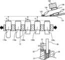
- FIGS. 6A and 6B are diagrams showing an example of application of the puncture mechanism and detection mechanism.
- FIG. 6A and FIG. 6B an example of application of the puncture mechanism and detection mechanism to a rack on which the holder 110 and the module 120 are installed is shown, with some of the surrounding components omitted.
- FIG. 6A is a plan view of the periphery of the rack 12 as seen from above.
- FIG. 6B is a partial cross-sectional view of the periphery of the rack 12 as seen from the side.
- the blood collection device 1 can also be provided with a rack 12 instead of a turntable 11 as a place to place the holder 110 and the module 120.
- the puncturing mechanism and the detection mechanism can also be used to adjust the amount of movement relative to the subject's finger 134 in the puncturing operation performed on the rack 12, the blood collection operation using the holder 110, and the treatment operation using a module 120 other than the puncturing module 120.
- the rack 12 is arranged in a line with a roughly rectangular parallelepiped shape.
- the rack 12 is provided with a number of portions that support the holders 110 in which the blood collection tubes are placed, and various modules 120.
- the portions that support the holders 110 and modules 120 are regularly spaced apart along the longitudinal direction of the rack 12.
- the rack 12 can be moved in both directions parallel to the longitudinal direction by a drive mechanism (not shown).
- the stepping motion of the rack 12 to the blood collection position where the finger placement area 131 is formed is controlled according to the blood collection operation or treatment operation.
- the holder 110 and the module 120 are each transported sequentially to the blood collection position where the finger placement area 131 is formed by the movement of the rack 12.
- the puncture mechanism and detection mechanism can be installed below the rack 12, as in the case of the turntable 11.
- the holders 110 for holding blood collection tubes include a first holder 110a for holding a first blood collection tube and a second holder 110b for holding a second blood collection tube, which are installed in the rack 12.
- these blood collection tubes for example, blood collection tubes coated with an anticoagulant for blood count tests, blood collection tubes containing a separating agent for biochemistry and immunological tests, etc. can be installed.
- the modules 120 are installed on the rack 12 and include a puncture module 120a which is the puncture section, a hemostatic module 120b which holds a protective material such as a bandage, and a hemostatic module 120c which holds a hemostatic material such as gauze.
- the puncturing mechanism When adjusting the amount of movement relative to the subject's finger 134 during a blood sampling operation using the holder 110 or a treatment operation using a module 120 other than the puncturing module 120, the puncturing mechanism functions as a moving mechanism that moves the holder 110 or the module 120 to press the blood collection tube, hemostatic material, or protective material against the subject's finger.
- the moving mechanism is composed of the lifting member 12, the base member 20, the movable support member 30, and a lifting drive mechanism that raises and lowers these members up and down.
- the holder 110 and the module 120 are transported sequentially to the blood collection position where the finger rest 131 is installed by the movement of the rack 12, and then are driven to rise by being pushed up by the movable support member 30.
- the blood collection tube is pressed against the subject's finger 134, and blood flowing out from the puncture site is collected.
- the protective material and hemostatic material are pressed against the subject's finger 134, and blood flowing out from the puncture site is stopped.
- the holder 110 and the module 120 may have different heights.
- the symbol d1 indicates the distance between the finger rest 131 and the reference position on the puncture module 120a in the initial position
- the symbol d2 indicates the distance between the finger rest 131 and the reference position on the blood collection tube placed on the holder 110a in the initial position
- the symbol d3 indicates the distance between the finger rest 131 and the reference position on the hemostasis module 120b in the initial position.
- these distances have a relationship of d1 ⁇ d2 ⁇ d3 .
- the amount of movement of the puncturing module 120 can be controlled to a preset target amount of movement (D+ ⁇ ), as in the case of the turntable 11.
- the amount of movement of the holder 110 and modules 120 other than the puncturing module 120, which is the puncturing part can be set to match the distance between the subject's finger 134 and the reference position on the holder 110 or module 120 in the initial position, based on the measurement result of the amount of movement of the puncturing module 120 measured when the puncturing module 120 is raised.
- the holder 110 and the module 120 can be transported in one axial direction by the rack 12, so that blood collection operations at the blood collection position and blood measurement operations at other than the blood collection position can be performed efficiently at each location. Since surrounding equipment and wiring do not interfere with the shaft or are not affected by the rotation of the turntable 11, the freedom of equipment installation and wiring can be improved in some cases.
- the present invention is not limited to the above-described embodiments, and various modifications are possible without departing from the spirit of the present invention.
- the present invention is not necessarily limited to having all of the configurations of the above-described embodiments. It is possible to replace part of the configuration of an embodiment with another configuration, add part of the configuration of an embodiment to another form, or omit part of the configuration of an embodiment.
Landscapes
- Health & Medical Sciences (AREA)
- Life Sciences & Earth Sciences (AREA)
- Heart & Thoracic Surgery (AREA)
- Medical Informatics (AREA)
- Biophysics (AREA)
- Pathology (AREA)
- Engineering & Computer Science (AREA)
- Biomedical Technology (AREA)
- Hematology (AREA)
- Physics & Mathematics (AREA)
- Molecular Biology (AREA)
- Surgery (AREA)
- Animal Behavior & Ethology (AREA)
- General Health & Medical Sciences (AREA)
- Public Health (AREA)
- Veterinary Medicine (AREA)
- Measurement Of The Respiration, Hearing Ability, Form, And Blood Characteristics Of Living Organisms (AREA)
Abstract
Priority Applications (2)
| Application Number | Priority Date | Filing Date | Title |
|---|---|---|---|
| CN202480015755.0A CN120813301A (zh) | 2023-06-28 | 2024-06-11 | 采血装置 |
| JP2025529613A JPWO2025004792A1 (fr) | 2023-06-28 | 2024-06-11 |
Applications Claiming Priority (2)
| Application Number | Priority Date | Filing Date | Title |
|---|---|---|---|
| JP2023106161 | 2023-06-28 | ||
| JP2023-106161 | 2023-06-28 |
Publications (1)
| Publication Number | Publication Date |
|---|---|
| WO2025004792A1 true WO2025004792A1 (fr) | 2025-01-02 |
Family
ID=93938750
Family Applications (1)
| Application Number | Title | Priority Date | Filing Date |
|---|---|---|---|
| PCT/JP2024/021211 Pending WO2025004792A1 (fr) | 2023-06-28 | 2024-06-11 | Dispositif de prélèvement de sang |
Country Status (3)
| Country | Link |
|---|---|
| JP (1) | JPWO2025004792A1 (fr) |
| CN (1) | CN120813301A (fr) |
| WO (1) | WO2025004792A1 (fr) |
Citations (8)
| Publication number | Priority date | Publication date | Assignee | Title |
|---|---|---|---|---|
| JP2001245872A (ja) * | 2000-03-02 | 2001-09-11 | Midori Nishikawa | 補助具 |
| JP2006223320A (ja) | 2005-01-21 | 2006-08-31 | Terumo Corp | 体液採取補助具および体液採取具 |
| JP2007054407A (ja) * | 2005-08-25 | 2007-03-08 | Terumo Corp | 穿刺装置及び穿刺針チップ |
| JP2008531156A (ja) * | 2005-03-03 | 2008-08-14 | エフ ホフマン−ラ ロッシュ アクチェン ゲゼルシャフト | 体液採取用穿刺システム |
| JP2008289939A (ja) * | 2001-06-12 | 2008-12-04 | Pelikan Technologies Inc | 皮膚の性状の一時的変化に対する適応手段を備えた自動最適化形切開器 |
| JP2009089818A (ja) | 2007-10-05 | 2009-04-30 | Panasonic Corp | 血液検査装置とその検査方法 |
| JP2017225519A (ja) | 2016-06-21 | 2017-12-28 | 株式会社日立ハイテクノロジーズ | 採血装置および採血方法 |
| JP2019047893A (ja) * | 2017-09-08 | 2019-03-28 | 株式会社日立ハイテクノロジーズ | 指採血装置 |
-
2024
- 2024-06-11 WO PCT/JP2024/021211 patent/WO2025004792A1/fr active Pending
- 2024-06-11 JP JP2025529613A patent/JPWO2025004792A1/ja active Pending
- 2024-06-11 CN CN202480015755.0A patent/CN120813301A/zh active Pending
Patent Citations (8)
| Publication number | Priority date | Publication date | Assignee | Title |
|---|---|---|---|---|
| JP2001245872A (ja) * | 2000-03-02 | 2001-09-11 | Midori Nishikawa | 補助具 |
| JP2008289939A (ja) * | 2001-06-12 | 2008-12-04 | Pelikan Technologies Inc | 皮膚の性状の一時的変化に対する適応手段を備えた自動最適化形切開器 |
| JP2006223320A (ja) | 2005-01-21 | 2006-08-31 | Terumo Corp | 体液採取補助具および体液採取具 |
| JP2008531156A (ja) * | 2005-03-03 | 2008-08-14 | エフ ホフマン−ラ ロッシュ アクチェン ゲゼルシャフト | 体液採取用穿刺システム |
| JP2007054407A (ja) * | 2005-08-25 | 2007-03-08 | Terumo Corp | 穿刺装置及び穿刺針チップ |
| JP2009089818A (ja) | 2007-10-05 | 2009-04-30 | Panasonic Corp | 血液検査装置とその検査方法 |
| JP2017225519A (ja) | 2016-06-21 | 2017-12-28 | 株式会社日立ハイテクノロジーズ | 採血装置および採血方法 |
| JP2019047893A (ja) * | 2017-09-08 | 2019-03-28 | 株式会社日立ハイテクノロジーズ | 指採血装置 |
Also Published As
| Publication number | Publication date |
|---|---|
| JPWO2025004792A1 (fr) | 2025-01-02 |
| CN120813301A (zh) | 2025-10-17 |
Similar Documents
| Publication | Publication Date | Title |
|---|---|---|
| JP4086859B2 (ja) | 採血システム | |
| US7749174B2 (en) | Method and apparatus for lancet launching device intergrated onto a blood-sampling cartridge | |
| EP1765152B1 (fr) | Appareil jetable pour analyse et capture d'echantillon integre | |
| US9744312B2 (en) | Methods and apparatus for lancet actuation | |
| US9839386B2 (en) | Body fluid sampling device with capacitive sensor | |
| US7141058B2 (en) | Method and apparatus for a body fluid sampling device using illumination | |
| JP6994910B2 (ja) | 採血装置および採血装置の作動方法 | |
| US20070064516A1 (en) | Methods and apparatus for lancet actuation | |
| US20090069716A1 (en) | Method and apparatus for a fluid sampling device | |
| JP7526681B2 (ja) | 採血装置 | |
| EP2838429B1 (fr) | Procédés et structures d'assemblage d'ensembles boîtier de lancettes pour dispositifs manuels de diagnostic médical | |
| JP2005504564A (ja) | 皮膚の性状の一時的変化に対する適応手段を備えた自動最適化形切開器具 | |
| CN201481407U (zh) | 脉象采集装置 | |
| WO2025004792A1 (fr) | Dispositif de prélèvement de sang | |
| CN111432725A (zh) | 传感器插入装置 | |
| JP4954999B2 (ja) | 小型容器からの液体吸引を最大限にする方法および装置 | |
| WO2025150395A1 (fr) | Dispositif de collecte de sang et procédé de collecte de sang | |
| JP2024168144A (ja) | 手指採血装置及び穿刺方法 | |
| CN213688767U (zh) | 小型飞行器主轴轴承装配预紧力自动检测校准装置 | |
| JPWO2025004792A5 (fr) | ||
| CN223828069U (zh) | 一种用于采血管的扫码装置 | |
| EP4659671A1 (fr) | Dispositif de collecte de sang | |
| EP1726259B1 (fr) | Dispositif de collecte des fluides corporels | |
| CN221903768U (zh) | 一种吸取皮肤分泌物质的吸取装置 | |
| CN218002478U (zh) | 涡盘检测设备 |
Legal Events
| Date | Code | Title | Description |
|---|---|---|---|
| 121 | Ep: the epo has been informed by wipo that ep was designated in this application |
Ref document number: 24827710 Country of ref document: EP Kind code of ref document: A1 |
|
| ENP | Entry into the national phase |
Ref document number: 2025529613 Country of ref document: JP Kind code of ref document: A |
|
| WWE | Wipo information: entry into national phase |
Ref document number: 2025529613 Country of ref document: JP |
|
| WWE | Wipo information: entry into national phase |
Ref document number: 202480015755.0 Country of ref document: CN |
|
| WWP | Wipo information: published in national office |
Ref document number: 202480015755.0 Country of ref document: CN |
|
| WWE | Wipo information: entry into national phase |
Ref document number: 2024827710 Country of ref document: EP |
|
| NENP | Non-entry into the national phase |
Ref country code: DE |
|
| ENP | Entry into the national phase |
Ref document number: 2024827710 Country of ref document: EP Effective date: 20260128 |
|
| ENP | Entry into the national phase |
Ref document number: 2024827710 Country of ref document: EP Effective date: 20260128 |