WO2025004847A1 - Procédé de production d'un article en verre - Google Patents
Procédé de production d'un article en verre Download PDFInfo
- Publication number
- WO2025004847A1 WO2025004847A1 PCT/JP2024/021625 JP2024021625W WO2025004847A1 WO 2025004847 A1 WO2025004847 A1 WO 2025004847A1 JP 2024021625 W JP2024021625 W JP 2024021625W WO 2025004847 A1 WO2025004847 A1 WO 2025004847A1
- Authority
- WO
- WIPO (PCT)
- Prior art keywords
- glass ribbon
- glass
- manufacturing
- conveying
- glass article
- Prior art date
- Legal status (The legal status is an assumption and is not a legal conclusion. Google has not performed a legal analysis and makes no representation as to the accuracy of the status listed.)
- Ceased
Links
Images



Classifications
-
- C—CHEMISTRY; METALLURGY
- C03—GLASS; MINERAL OR SLAG WOOL
- C03B—MANUFACTURE, SHAPING, OR SUPPLEMENTARY PROCESSES
- C03B17/00—Forming molten glass by flowing-out, pushing-out, extruding or drawing downwardly or laterally from forming slits or by overflowing over lips
- C03B17/06—Forming glass sheets
-
- C—CHEMISTRY; METALLURGY
- C03—GLASS; MINERAL OR SLAG WOOL
- C03B—MANUFACTURE, SHAPING, OR SUPPLEMENTARY PROCESSES
- C03B33/00—Severing cooled glass
- C03B33/02—Cutting or splitting sheet glass or ribbons; Apparatus or machines therefor
Definitions
- This disclosure relates to a method for manufacturing glass articles.
- Patent Document 1 discloses an example of a method for manufacturing a glass roll from a glass ribbon.
- a glass ribbon is continuously formed from molten glass using the down-draw method.
- the conveying direction of the formed glass ribbon is changed from vertical to horizontal.
- unnecessary portions on one side and the other side of the width of the glass ribbon are cut off and removed from the glass ribbon.
- the glass ribbon from which the unnecessary portions have been removed is wound up in a roll around a winding core to form a glass roll.
- defective cracks When manufacturing glass articles from glass ribbons as described above, production losses of glass articles can occur due to unintentional cracks that occur in the glass ribbon (hereinafter referred to as "defective cracks").
- production loss may occur when glass ribbon 100 transported in direction A is repeatedly cut at the downstream end of the transport path to continuously cut glass sheets 200 from the glass ribbon 100.
- the glass ribbon 100 may break, causing a defective crack C.
- the defective crack C advances toward the upstream side (direction B) of the glass ribbon 100, opposite to the transport direction (direction A) of the glass ribbon 100. Note that one side portion 101 and the other side portion 102 in the width direction of the glass ribbon 100 shown in the figure are separated by the defective crack C as a boundary.
- the defective crack C When the above-mentioned defective crack C occurs, it becomes impossible to cut out a new glass sheet 200 from the glass ribbon 100 until the defective crack C is removed from the glass ribbon 100.
- the defective crack C does not stop progressing upstream and continues to exist on the glass ribbon 100 unless it is deflected to the widthwise edge 100a of the glass ribbon 100. Therefore, cutting of the glass sheet 200 has to be stopped until the defective crack C accidentally deflects to the widthwise edge 100a. This causes a production loss of the glass sheet 200. Therefore, there has been a demand for the establishment of a technology that can quickly remove the defective crack C from the glass ribbon 100 when the defective crack C occurs in the glass ribbon 100.
- the technical problem to be solved is to be able to quickly remove defective cracks from a glass ribbon when the defective cracks occur in the glass ribbon when a glass article is manufactured from the glass ribbon.
- the first method for manufacturing a glass article to solve the above problem includes a conveying step of conveying a glass ribbon along a conveying path, and an acquisition step of acquiring a glass article from the glass ribbon at the downstream end of the conveying path, and further includes a guide step of guiding a defective crack that propagates toward the upstream side of the glass ribbon to a widthwise edge of the glass ribbon when the defective crack occurs in the glass ribbon, and is characterized in that in the guide step, a tension difference is provided between the tension generated in one side portion of the glass ribbon in the width direction and the tension generated in the other side portion separated by the defective crack.
- the induction process As the induction process is performed, a tension difference occurs between the tension generated in one side portion of the glass ribbon in the width direction and the tension generated in the other side portion separated by the defective crack (hereinafter, the portion with the greater tension is referred to as the "high tension portion"). Due to the occurrence of this tension difference, the defective crack advances toward one of the two width direction edges of the glass ribbon that is included in the high tension portion, and quickly reaches that edge. As a result, the defective crack can be removed from the glass ribbon. Thus, according to this manufacturing method, when a defective crack occurs in the glass ribbon, it becomes possible to quickly remove the defective crack from the glass ribbon.
- the second method for manufacturing a glass article is the same as the first manufacturing method described above, except that in the induction step, the conveying speed of one of the sections on one side and the other side is accelerated to create a tension difference.
- the tension difference is created by accelerating the conveying speed of one of the two sections, so that a tension difference can be created quickly and reliably between the two sections.
- the conveying speed is accelerated, unlike when the conveying speed is decelerated, the risk of wrinkles or sagging in the glass ribbon occurring during the induction process can be eliminated.
- the third method for manufacturing a glass article is the first or second manufacturing method described above, in which in the induction step, a tension difference is created by applying to one of the one side portion and the other side portion (1) an external force directed downstream in the conveying direction of the glass ribbon, or (2) an external force having a component directed downstream in the conveying direction of the glass ribbon and a component directed outward from the center in the width direction.
- the above-mentioned external force (1) or (2) is applied to one of the two portions.
- Both of the external forces (1) and (2) have a component oriented toward the downstream side of the conveying direction of the glass ribbon. This has the effect of reliably creating a tension difference between the two portions as the external force is applied, and the effect of making it easier for bad cracks to progress toward the widthwise edge of the glass ribbon.
- the fourth method for manufacturing a glass article is the third manufacturing method described above, but in a different form, an external force is applied to a portion of the glass ribbon that is located between the widthwise edge and the defective crack.
- an external force is applied to a portion of the glass ribbon that is on the inside of the widthwise edge. This makes it possible to avoid applying a load to the widthwise edge, which is a portion of the glass ribbon that has low strength, when the guidance process is performed. This makes it possible to eliminate the risk of new defective cracks occurring from the widthwise edge that is subjected to the load.
- the fifth method for manufacturing a glass article is the third or fourth manufacturing method described above, except that an external force is applied to the portion having the smaller width dimension between the one side portion and the other side portion.
- the defective crack propagates toward one of the two widthwise edges of the glass ribbon that is closer to the defective crack. This shortens the time it takes for the defective crack to reach the widthwise edge, making it possible to more quickly remove the defective crack from the glass ribbon.
- the sixth method for manufacturing a glass article is any one of the third to fifth manufacturing methods described above, in which, when applying an external force, a feed member having a feed direction that is the same as the direction of the external force is brought into contact with the glass ribbon.
- an external force is applied by bringing a feed member into contact with the glass ribbon, so that the external force can be applied stably.
- the seventh method for manufacturing a glass article is the sixth method described above, except that the feed member is a roller.
- a roller is used as the feed member, making it possible to apply an external force with a simple configuration.
- the eighth method for manufacturing a glass article is the seventh method described above, except that the peripheral speed of the roller is faster than the conveying speed of the glass ribbon when the roller comes into contact with the glass ribbon.
- an external force can be applied by the frictional force between the peripheral surface of the roller and the surface of the glass ribbon (one of the one side portion and the other side portion).
- the ninth method for manufacturing a glass article is any one of the third to fifth manufacturing methods described above, in which the external force is applied by spraying gas toward the glass ribbon.
- an external force is applied by spraying gas, so that it is easy to apply an external force even if the width dimension of the area to which the external force is to be applied (one of the area on one side and the area on the other side) is small.
- the tenth method for manufacturing a glass article is any one of the first to ninth manufacturing methods described above, in which the induction step involves capturing an image of the glass ribbon and processing the image to detect the occurrence of defective cracks.
- the tenth method for manufacturing a glass article uses images of the glass ribbon and image processing, making it possible to accurately detect defective cracks that have occurred in the glass ribbon.
- the eleventh method for manufacturing a glass article is any one of the first to tenth manufacturing methods described above, in which the obtaining step involves repeatedly cutting the glass ribbon in the width direction to continuously obtain a glass plate as the glass article.
- the glass ribbon is repeatedly cut in the width direction, which makes it easier for defective cracks to occur at the ends (cut ends) formed in the glass ribbon as a result of cutting. Therefore, this manufacturing method makes it possible to advantageously enjoy the effect of being able to quickly remove defective cracks from the glass ribbon.
- the twelfth method for manufacturing a glass article is any one of the first to eleventh manufacturing methods described above, in which the glass ribbon has a thickness of 200 ⁇ m or less, and is subjected to a forming process, a conveying direction changing process after the forming process, and a cutting process of unnecessary parts after the conveying direction changing process, and then is supplied to a conveying process, in which the glass ribbon is drawn out vertically from the molten glass supplied to the forming body and formed, in which the conveying direction changing process changes the conveying direction of the glass ribbon after the forming process from the vertical direction to the horizontal direction, and in which the cutting process of unnecessary parts removes the unnecessary parts present on one side and the other side of the width direction of the glass ribbon by cutting them from the glass ribbon.
- the glass ribbon is extremely thin at 200 ⁇ m or less, and an unnecessary portion cutting process is performed, so that defective cracks are more likely to occur in the glass ribbon that has undergone the unnecessary portion cutting process. Therefore, with this manufacturing method, it is possible to more effectively enjoy the effect of being able to quickly remove defective cracks from the glass ribbon.
- the thirteenth method for manufacturing a glass article for solving the above problem is a method for manufacturing a glass article comprising a conveying step of conveying a glass ribbon along a conveying path, and an acquisition step of acquiring a glass article from the glass ribbon at the downstream end of the conveying path, and further comprises a guiding step of guiding a defective crack to a widthwise edge of the glass ribbon when a defective crack that propagates toward the upstream side of the glass ribbon occurs in the glass ribbon, and is characterized in that in the guiding step, an external force for guiding is applied to one of one side portion and the other side portion in the widthwise direction of the glass ribbon separated by the defective crack.
- the thirteenth method for manufacturing a glass article can achieve the same effects and advantages as the first method for manufacturing the glass article.
- the method for manufacturing a glass article according to the present disclosure makes it possible to quickly remove defective cracks from a glass ribbon when the glass ribbon is used to manufacture a glass article.
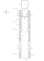
- FIG. 2 is a side view showing a method for manufacturing a glass article.
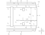
- FIG. 2 is a plan view showing a method for manufacturing a glass article.
- FIG. FIG. FIG. 11 is a side view showing a modified example of the guiding step.
- FIG. 11 is a plan view for explaining a problem in the conventional art.
- a glass sheet Gs is cut out as a glass article from a glass ribbon G formed using a downdraw method (overflow downdraw method in the illustrated example).
- This manufacturing method includes, as main steps, a forming step P1, a conveying direction changing step P2, an unnecessary part cutting step P3, a conveying step P4, and an acquisition step P5.
- the glass ribbon G is formed by drawing it out in the vertical direction (Z direction) from the molten glass MG supplied to the forming body 1.
- a roller group 2 arranged in multiple layers above and below is used to draw out the glass ribbon G.
- the roller group 2 includes edge rollers 3, annealer rollers 4, and support rollers 5.
- the edge rollers 3 contact the widthwise ends of the glass ribbon G directly below the forming body 1 to suppress shrinkage of the glass ribbon G in the widthwise direction (X direction).
- the annealer rollers 4 guide the downward movement of the glass ribbon G, which is slowly cooled to a temperature below the strain point in an annealing furnace (not shown).
- the support rollers 5 support and pull downward the glass ribbon G, whose temperature has been reduced to near room temperature in a cooling chamber (not shown).
- Unwanted parts Gx are present on one side and the other side of the formed glass ribbon G in the width direction (in Figure 2, the boundary between the unwanted parts Gx and other parts is shown by a two-dot chain line).
- the unwanted parts Gx are parts that are cut off and removed from the glass ribbon G in the unwanted part cutting process P3, which is performed downstream of the forming process P1.
- the unwanted parts Gx include ears that are thicker than other parts of the glass ribbon G.
- the thickness of the glass ribbon G is, for example, 200 ⁇ m or less, 100 ⁇ m or less, or 50 ⁇ m or less.
- the conveying direction of the glass ribbon G after the forming process P1 is changed from the vertical direction to the horizontal direction (Y direction).
- a roller conveyor 6 consisting of multiple rollers is used to change the conveying direction of the glass ribbon G.
- the glass ribbon G is transported downstream by a belt conveyor 7 and a strip-shaped protective sheet 9 (e.g., a strip-shaped resin sheet) moving on a support table 8, and sent to the unnecessary portion cutting process P3.
- a strip-shaped protective sheet 9 e.g., a strip-shaped resin sheet
- the unnecessary portion Gx is cut and removed from the glass ribbon G.
- a laser cutting device 10 is used to cut off the unnecessary portion Gx.
- a laser L is irradiated from the device 10 toward the glass ribbon G, and the unnecessary portion Gx is cut off by continuously cutting the glass ribbon G along the longitudinal direction (Y direction). After cutting, the unnecessary portion Gx is removed from the glass ribbon G transport path 11 downstream of the unnecessary portion cutting process P3 and discarded.
- the glass ribbon G after the unnecessary portion cutting process P3 (the glass ribbon G from which the unnecessary portion Gx has been removed) is transported along the transport path 11 and sent to the acquisition process P5.
- a strip-shaped protective sheet 9 moving on a belt conveyor 12 and a board 13 is used to transport the glass ribbon G in the transport process P4.
- an imaging device 14 and a pair of rollers 15, 15 are arranged, which are used in the guidance process P6 described below.
- the pair of rollers 15, 15 are arranged corresponding to one side and the other side of the width direction of the glass ribbon G, respectively. Each roller 15 is located between the width direction center and the width direction edge Ge of the glass ribbon G when viewed from the Z direction. Both of the pair of rollers 15, 15 are located above the board 13. Each roller 15 can move in the vertical direction, and can contact and move away from the surface of the glass ribbon G as it moves. Each roller 15 contacts the surface of the glass ribbon G when used in the guiding process P6, and moves away from the surface when not in use. The function of the imaging device 14 and the operation of the pair of rollers 15, 15 in the guiding process P6 will be described in detail later.
- the glass ribbon G is repeatedly cut in the width direction (X direction) at the downstream end 11e of the transport path 11 to continuously obtain glass sheets Gs from the glass ribbon G.
- the cutting of the glass ribbon G in the width direction can be performed using a known cutting device or by cutting work performed by an operator.
- the multiple glass sheets Gs obtained from the glass ribbon G are packaged after being stacked alternately with buffer sheets, for example.
- this manufacturing method further includes the induction step P6 shown in Figures 3, 4a, and 4b.
- the guiding process P6 is a process that is executed when a defective crack C that progresses toward the upstream side (D1 direction) of the glass ribbon G occurs, as shown in FIG. 3.
- the defective crack C is guided to the widthwise edge Ge of the glass ribbon G, and the defective crack C is removed from the glass ribbon G.
- an example is given of a defective crack C occurring from the cut end (the leading end of the glass ribbon G) when the glass ribbon G is cut in the width direction in the acquiring process P5.
- the acquiring process P5 is interrupted to stop acquiring the glass sheet Gs from the glass ribbon G.
- the glass ribbon G that has reached the downstream end 11e of the transport path 11 is continuously discarded.
- the image processing device can detect defective cracks C based on the image captured by the imaging device 14, for example by using a differential image (imaging the difference in pixel values between the captured image and an image captured in the past).
- a differential image imaging the difference in pixel values between the captured image and an image captured in the past.
- other image processing may be used to detect defective cracks C as long as it is possible to determine the presence or absence of defective cracks C.
- the one roller 15 is the roller 15 arranged above the one side portion G1, which is the portion of the glass ribbon G that has a smaller width dimension, of the one side portion G1 and the other side portion G2.
- the roller 15 is brought into contact with the one side portion G1 to apply an external force F to the one side portion G1 in the downstream direction of the conveying direction of the glass ribbon G.
- the feed direction of the roller 15 is the same direction as the direction of the external force F to be applied, and further, the peripheral speed V1 of the roller 15 is made faster than the conveying speed V2 of the glass ribbon G.
- the position where the external force F is applied is between the widthwise edge Ge and the defective crack C in the X direction.
- the one-side portion G1 When the roller 15 is brought into contact with the one-side portion G1, the one-side portion G1 is sandwiched in the thickness direction (Z direction) between the roller 15 and the board 13.
- the board 13 functions as a support member that supports the roller 15 via the glass ribbon G (one-side portion G1).
- the conveying speed of the one-side portion G1 is accelerated.
- This causes a tension difference between the one-side portion G1 and the other-side portion G2.
- the tension T1 acting on the one-side portion G1 becomes greater than the tension T2 acting on the other-side portion G2.
- This tension difference causes the defective crack C to advance (advance in the D2 direction) toward the edge Ge included in the one-side portion G1 of both widthwise ends Ge, Ge of the glass ribbon G, and quickly reaches the edge Ge.
- the defective crack C reaches the widthwise edge Ge, the progression of the defective crack C to the upstream side is stopped.
- the part of the glass ribbon G upstream of the defective crack C is cut in the width direction. This separates the section in the longitudinal direction of the glass ribbon G where the defective crack C exists from the section where the defective crack C does not exist. Accordingly, the defective crack C is removed from the glass ribbon G, and the induction process P6 is completed. After the induction process P6 is completed, the execution of the interrupted acquisition process P5 is resumed.
- a pair of rollers 15, 15 is arranged, and one of the rollers 15 is used to guide the defective crack C that occurs in the glass ribbon G to the widthwise edge Ge.
- one of the pair of rollers 15, 15 does not necessarily have to be present, and only a single roller 15 may be arranged. This single roller 15 may be arranged corresponding to either one side or the other side in the width direction of the glass ribbon G.
- the defective crack C can be guided to the widthwise edge Ge regardless of the position where the defective crack C occurs (whether it is closer to one side or the other side in the width direction).
- the manner in which the defective cracks C occur is exemplified by the case in which the defective cracks C occur from the cut end (the leading end of the glass ribbon G) when the glass ribbon G is cut in the width direction in the acquisition process P5.
- the manner in which the defective cracks C occur is not limited to this, and there are also cases in which the defective cracks C occur from the width direction edge Ge of the glass ribbon G after the unnecessary portion cutting process P3, and cases in which the defective cracks C occur in the glass ribbon G upstream of the unnecessary portion cutting process P3.
- the guiding process P6 may be executed. Even in these cases, by executing the guiding process P6 with the same arrangement of the imaging device 14 and the pair of rollers 15, 15 as in the above embodiment, the defective cracks C that have occurred in the glass ribbon G can be guided to the width direction edge Ge.
- the external force F is applied by contacting the roller 15 with one side portion G1 of the glass ribbon G.
- the external force F may be applied by air A (gas) sprayed from the spray nozzle 16 toward the glass ribbon G on the board 13.
- the spray nozzle 16 is directed toward the downstream side of the conveying direction of the glass ribbon G from above the conveying path 11.
- the external force F may be applied manually by an operator.
- the conveying speed of one side portion G1 is accelerated.
- this is not limited to the above, and a tension difference may be created between one side portion G1 and the other side portion G2 by decelerating the conveying speed of one side portion G1.
- the glass sheet Gs serving as the glass article is cut out from the glass ribbon G, but the glass ribbon G may also be wound into a roll to produce a glass roll.
Landscapes
- Chemical & Material Sciences (AREA)
- Engineering & Computer Science (AREA)
- Materials Engineering (AREA)
- Organic Chemistry (AREA)
- Re-Forming, After-Treatment, Cutting And Transporting Of Glass Products (AREA)
Abstract
L'invention concerne un procédé de production d'un article en verre, le procédé comprenant : une étape de transport P4 pour transporter un ruban de verre G le long d'un trajet de transport 11 ; et une étape d'acquisition P5 pour acquérir une plaque de verre Gs à partir du ruban de verre G au niveau d'une extrémité aval 11e du trajet de transport 11. Le procédé comprend en outre une étape de guidage P6 lors de laquelle, lorsqu'une fissure défectueuse C progressant en amont dans le ruban de verre G apparaît dans le ruban de verre G, la fissure défectueuse C est guidée vers un bord d'extrémité dans le sens de la largeur Ge du ruban de verre G. Lors de l'étape de guidage P6, une différence de tension est créée entre une partie latérale G1 et l'autre partie latérale G2 dans la direction de la largeur du ruban de verre G, la partie latérale G1 et l'autre partie latérale G2 étant divisées au niveau de la fissure défectueuse C qui sert de limite.
Applications Claiming Priority (2)
| Application Number | Priority Date | Filing Date | Title |
|---|---|---|---|
| JP2023-105995 | 2023-06-28 | ||
| JP2023105995A JP2025005704A (ja) | 2023-06-28 | 2023-06-28 | ガラス物品の製造方法 |
Publications (1)
| Publication Number | Publication Date |
|---|---|
| WO2025004847A1 true WO2025004847A1 (fr) | 2025-01-02 |
Family
ID=93938902
Family Applications (1)
| Application Number | Title | Priority Date | Filing Date |
|---|---|---|---|
| PCT/JP2024/021625 Ceased WO2025004847A1 (fr) | 2023-06-28 | 2024-06-14 | Procédé de production d'un article en verre |
Country Status (2)
| Country | Link |
|---|---|
| JP (1) | JP2025005704A (fr) |
| WO (1) | WO2025004847A1 (fr) |
Citations (2)
| Publication number | Priority date | Publication date | Assignee | Title |
|---|---|---|---|---|
| JP2017534557A (ja) * | 2014-10-10 | 2017-11-24 | コーニング インコーポレイテッド | ガラスの切断を誘導してクラックアウトを防止する熱障壁 |
| WO2021149519A1 (fr) * | 2020-01-20 | 2021-07-29 | 日本電気硝子株式会社 | Procédé de production d'un film de verre |
-
2023
- 2023-06-28 JP JP2023105995A patent/JP2025005704A/ja active Pending
-
2024
- 2024-06-14 WO PCT/JP2024/021625 patent/WO2025004847A1/fr not_active Ceased
Patent Citations (2)
| Publication number | Priority date | Publication date | Assignee | Title |
|---|---|---|---|---|
| JP2017534557A (ja) * | 2014-10-10 | 2017-11-24 | コーニング インコーポレイテッド | ガラスの切断を誘導してクラックアウトを防止する熱障壁 |
| WO2021149519A1 (fr) * | 2020-01-20 | 2021-07-29 | 日本電気硝子株式会社 | Procédé de production d'un film de verre |
Also Published As
| Publication number | Publication date |
|---|---|
| JP2025005704A (ja) | 2025-01-17 |
Similar Documents
| Publication | Publication Date | Title |
|---|---|---|
| JP6796282B2 (ja) | ガラスフィルムの製造方法 | |
| CN103347827B (zh) | 板状玻璃的切断方法及其切断装置 | |
| JP6924379B2 (ja) | ガラスフィルムの製造方法 | |
| WO2012157639A1 (fr) | Procédé et appareil de production d'un rouleau de verre | |
| KR20160048718A (ko) | 유리 필름 리본 제조 방법 및 유리 필름 리본 제조 장치 | |
| CN112074476B (zh) | 玻璃卷的制造方法 | |
| KR20150087277A (ko) | 유리 리본으로부터 유리 시트를 분리하는 분리 장치 및 방법 | |
| TW201838902A (zh) | 玻璃卷之製造方法 | |
| WO2018070209A1 (fr) | Procédé de production d'une couche vitreuse | |
| WO2017208677A1 (fr) | Procédé de production de film de verre | |
| WO2018168381A1 (fr) | Procédé de fabrication de film de verre | |
| WO2022114021A1 (fr) | Procédé de fabrication de film de verre | |
| JP6136070B2 (ja) | ガラスフィルムリボン製造方法及びガラスフィルムリボン製造装置 | |
| JP2025005704A (ja) | ガラス物品の製造方法 | |
| JP6056710B2 (ja) | 薄板ガラスの搬送方法および搬送装置 | |
| JP7415265B2 (ja) | ガラスロールの製造方法 | |
| TW202239721A (zh) | 卷體的製造方法 | |
| WO2021149519A1 (fr) | Procédé de production d'un film de verre | |
| CN115996895B (zh) | 玻璃物品的制造方法 | |
| TWI832089B (zh) | 玻璃卷的製造方法 | |
| JP2025053925A (ja) | ガラス物品の製造装置および製造方法、並びに搬送装置 | |
| CN114929605A (zh) | 玻璃膜的制造方法以及玻璃膜的制造装置 | |
| WO2025100098A1 (fr) | Appareil de production d'article en verre |
Legal Events
| Date | Code | Title | Description |
|---|---|---|---|
| 121 | Ep: the epo has been informed by wipo that ep was designated in this application |
Ref document number: 24831712 Country of ref document: EP Kind code of ref document: A1 |
|
| NENP | Non-entry into the national phase |
Ref country code: DE |