WO2025004882A1 - Ressort hélicoïdal et procédé de fabrication de ressort hélicoïdal - Google Patents
Ressort hélicoïdal et procédé de fabrication de ressort hélicoïdal Download PDFInfo
- Publication number
- WO2025004882A1 WO2025004882A1 PCT/JP2024/021863 JP2024021863W WO2025004882A1 WO 2025004882 A1 WO2025004882 A1 WO 2025004882A1 JP 2024021863 W JP2024021863 W JP 2024021863W WO 2025004882 A1 WO2025004882 A1 WO 2025004882A1
- Authority
- WO
- WIPO (PCT)
- Prior art keywords
- coil spring
- wire
- coating layer
- coating
- manufacturing
- Prior art date
- Legal status (The legal status is an assumption and is not a legal conclusion. Google has not performed a legal analysis and makes no representation as to the accuracy of the status listed.)
- Ceased
Links
Images


Classifications
-
- F—MECHANICAL ENGINEERING; LIGHTING; HEATING; WEAPONS; BLASTING
- F16—ENGINEERING ELEMENTS AND UNITS; GENERAL MEASURES FOR PRODUCING AND MAINTAINING EFFECTIVE FUNCTIONING OF MACHINES OR INSTALLATIONS; THERMAL INSULATION IN GENERAL
- F16F—SPRINGS; SHOCK-ABSORBERS; MEANS FOR DAMPING VIBRATION
- F16F1/00—Springs
- F16F1/02—Springs made of steel or other material having low internal friction; Wound, torsion, leaf, cup, ring or the like springs, the material of the spring not being relevant
- F16F1/04—Wound springs
- F16F1/06—Wound springs with turns lying in cylindrical surfaces
-
- F—MECHANICAL ENGINEERING; LIGHTING; HEATING; WEAPONS; BLASTING
- F16—ENGINEERING ELEMENTS AND UNITS; GENERAL MEASURES FOR PRODUCING AND MAINTAINING EFFECTIVE FUNCTIONING OF MACHINES OR INSTALLATIONS; THERMAL INSULATION IN GENERAL
- F16F—SPRINGS; SHOCK-ABSORBERS; MEANS FOR DAMPING VIBRATION
- F16F1/00—Springs
- F16F1/02—Springs made of steel or other material having low internal friction; Wound, torsion, leaf, cup, ring or the like springs, the material of the spring not being relevant
- F16F1/04—Wound springs
- F16F1/12—Attachments or mountings
Definitions
- the present invention relates to a coil spring and a method for manufacturing a coil spring.
- Coil springs have been used as spring components in vehicle suspension systems and the like.
- Coil springs are generally formed by winding a wire rod with a circular cross section (see, for example, Patent Document 1).
- these coil springs are provided with a covering tube to suppress abnormal noises that occur when the wire rods come into contact with each other (inter-wire contact) when compressed by vibration, impact, etc.
- coil springs are also required to be resistant to wear caused by such contact.
- the present invention has been made in consideration of the above, and aims to provide a coil spring and a method for manufacturing a coil spring that can ensure wear resistance even when there are narrow gaps between the wires.
- the coil spring of the present invention is a coil spring formed by winding a wire in a spiral shape, and is characterized in that a coating layer is provided on at least a portion of the surface of the wire in the portion where the gap between the wires is narrower than the wire diameter of the wire, and the coating layer contains a slip agent.
- the coil spring according to the present invention is characterized in that, in the above invention, the wire is coated with a coating film, and the coating layer is provided on the coating film.
- the coil spring according to the present invention is characterized in that the coating layer contains a rust inhibitor.
- the method for manufacturing a coil spring according to the present invention is a method for manufacturing a coil spring by spirally winding a wire, and is characterized in that a coating layer is formed by applying a coating agent containing a slip agent to at least a portion of the surface of the wire in the portion where the gap between the wires is narrower than the wire diameter of the wire.
- the method for manufacturing a coil spring according to the present invention is characterized in that, in the above invention, the coating layer is formed by immersing the wire in the liquid coating agent.
- the method for manufacturing a coil spring according to the present invention is characterized in that, in the above invention, the coating layer is formed by spraying the coating agent onto the wire.
- the method for manufacturing a coil spring according to the present invention is characterized in that, in the above invention, the wire is coated with a coating film, and the coating layer is formed on the coating film.
- the method for manufacturing a coil spring according to the present invention is characterized in that in the above invention, the coating film is subjected to a surface treatment, and the coating layer is formed on the coating film that has been subjected to the surface treatment.
- the present invention has the effect of ensuring wear resistance even when there are narrow gaps between wires.
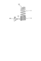
- FIG. 1 is a plan view showing the configuration of a coil spring according to an embodiment of the present invention.
- FIG. 2 is a diagram (part 1) for explaining an example of a method for forming a coating layer in a coil spring according to an embodiment of the present invention.
- FIG. 3 is a diagram (part 2) for explaining an example of a method for forming a coating layer in a coil spring according to an embodiment of the present invention.
- FIG. 1 is a plan view showing the configuration of a coil spring according to an embodiment of the present invention.
- the coil spring 1 is formed by, for example, winding a wire made of spring steel in a spiral shape around a predetermined axis. In this embodiment, an example will be described in which the predetermined axis coincides with the central axis N of the coil spring 1.
- the coil spring 1 is used, for example, as a suspension spring, an engine valve spring, a drive system component (clutch) spring, a tensioner spring, etc.
- the coil spring 1 is formed by winding a wire in a spiral shape around a central axis N.
- the wire is formed using, for example, spring steel or other metal materials. Examples of other metal materials include materials made of a single metal and materials made of an alloy.
- a wire formed using a resin or the like may be used.
- FIG. 1 a configuration is shown in which the diameter (the diameter of the circle formed by the wire when viewed from the direction of the central axis N) due to the winding (winding) is partially different in the direction of the central axis N, but this is not limited to this, and the diameter can be appropriately changed in design.
- FIG. 1 a configuration is shown in which the diameter (the diameter of the circle formed by the wire when viewed from the direction of the central axis N) due to the winding (winding) is partially different in the direction of the central axis N, but this is not limited to this, and the diameter can be appropriately changed in design.
- FIG. 1 a configuration is shown in which the diameter (
- the coil spring may also be, for example, a coil spring in which a wire is wound around a center line that is at least partially curved.
- the coil spring 1 has a pitch that is different in parts along the central axis N, which corresponds to the distance between the central axes of the wire rods. Therefore, in the coil spring 1, the gap between the wire rods is different in parts along the central axis N.
- the gap between the wire rods corresponds to the distance between the wire rods in the central axis N direction (gap distance Is (see Figure 1)), and for example, in the example shown in Figure 1, the gap on the right side of Figure 1 is smaller than the gap on the left side.
- the coil spring 1 has a first winding portion 11 and a second winding portion 12 that is continuous with the first winding portion 11.
- the gap distance of the second winding portion 12 is relatively narrower than the gap distance of the first winding portion 11.
- the gap distance Is of the second winding portion 12 is smaller than the wire diameter Rr of the wire constituting the coil spring 1.
- the wire diameter Rr corresponds to the diameter of the wire cross section when the wire cross section is circular in a cross section cut on a plane perpendicular to the longitudinal direction of the wire.
- the wire diameter corresponds to, for example, the length of one side forming the outer edge or the length of the diagonal in the cross section cut on a plane perpendicular to the longitudinal direction of the wire.
- the length of the cross section of this angular wire corresponds to the "wire diameter".
- the gap distance of the first winding portion 11 is described as being larger than the wire diameter Rr even at its narrowest gap.
- a coating layer 12a is provided on the second winding portion 12. This coating layer 12a is formed on the outermost surface of the coil spring 1.
- the coating layer 12a is, for example, a film formed by a coating agent in which a polymeric material or an inorganic material is mixed with a slip agent, that is, a polymeric film containing a slip agent, or an inorganic film containing a slip agent.
- the polymer material can be selected from thermoplastic resins, thermoplastic elastomers, thermosetting resins, thermosetting elastomers, etc.
- Thermoplastic resins include various resins such as polyolefin resin, polyvinyl chloride resin, polyvinylidene chloride resin, polystyrene resin, polyester resin, polyamide resin, polycarbonate resin, polyvinyl acetate resin, polyurethane resin, polytetrafluoroethylene resin, and polyacrylic resin.
- Thermoplastic elastomers include various elastomers such as styrene-based thermoplastic elastomers, olefin-based thermoplastic elastomers, vinyl chloride-based thermoplastic elastomers, urethane-based thermoplastic elastomers, and amide-based thermoplastic elastomers.
- Thermosetting resins include various resins such as phenolic resins, epoxy resins, melamine resins, urea resins, unsaturated polyester resins, alkyd resins, polyurethanes, and thermosetting polyimides.
- Thermosetting elastomers include various resins such as isoprene rubber, butadiene rubber, styrene-butadiene rubber, acrylonitrile-butadiene rubber, chloroprene rubber, nitrile rubber, butyl rubber, ethylene propylene rubber, chlorosulfonated polyethylene, acrylic rubber, fluororubber, epichlorohydrin rubber, urethane rubber, and silicone rubber.
- Ceramics include oxides such as aluminum oxide, magnesium oxide, zinc oxide, titanium oxide, and silicon oxide, nitrides such as boron nitride, aluminum nitride, and silicon nitride, carbides such as silicon carbide and boron carbide, and composites of these.
- Slip agents include, for example, hydrocarbon compounds, oxyfatty acids or their metal salts, fatty alcohols, silicone compounds, and fluorine compounds.
- hydrocarbon compounds examples include low molecular weight waxes, paraffin waxes, polyethylene waxes, and chlorinated hydrocarbons.
- oxyfatty acids or metal salts thereof include higher fatty acids such as lauric acid, stearic acid, and behenic acid, hydroxystearic acid, and metal salts thereof (metal salts such as zinc), etc.
- fatty alcohols examples include stearyl alcohol, lauryl alcohol, palmityl alcohol, etc.
- silicone compounds examples include polydimethylsiloxane, polyether-modified polydimethylsiloxane, polymethylalkylsiloxane, etc.
- fluorine-based compounds include polytetrafluoroethylene (PTFE); tetrafluoroethylene-perfluoromethyl vinyl ether copolymer (MFA), tetrafluoroethylene-perfluoroethyl vinyl ether copolymer (EFA), tetrafluoroethylene-perfluoropropyl vinyl ether copolymer, and other tetrafluoroethylene-perfluoroalkyl vinyl ether copolymers (PFAs).
- PTFE polytetrafluoroethylene
- MFA tetrafluoroethylene-perfluoromethyl vinyl ether copolymer
- EDA tetrafluoroethylene-perfluoroethyl vinyl ether copolymer
- PFAs tetrafluoroethylene-perfluoropropyl vinyl ether copolymer
- Slip agents also include inorganic fillers (calcium carbonate, talc, kaolin clay, silica, mica, calcium silicate, aluminum hydroxide, alumina, barium sulfate, titanium dioxide, zinc oxide, etc.).
- inorganic fillers calcium carbonate, talc, kaolin clay, silica, mica, calcium silicate, aluminum hydroxide, alumina, barium sulfate, titanium dioxide, zinc oxide, etc.
- a rust inhibitor or a material having wear resistance may be added to the slip agent.
- the rust inhibitor include amine-based organic compounds, condensed aluminum phosphate, and fatty acid salts.
- examples of the amine-based organic compounds include nitrites, carbonates, and carboxylates of amines.
- materials that function as lubricants or surfactants can also be used as the slip agent.
- the slip agent may be contained in the polymeric material film or inorganic film in a molecular dispersed state or in a particulate form.
- a method for forming the coating layer 12a in the second winding portion 12 will be described with reference to Figures 2 and 3.
- Examples of methods for forming the coating layer 12a include application methods such as dipping and spraying. Below, the dipping and spraying methods will be described, but other known methods such as application with a brush or nozzle can also be used.
- FIG. 2 is a diagram for explaining an example of a method for forming a coating layer in a coil spring according to an embodiment of the present invention.
- the immersion method as shown in Fig. 2, in a coil spring 100 having a first winding portion 111 whose winding pattern of the wire corresponds to the first winding portion 11 and a second winding portion 112 whose winding pattern of the wire corresponds to the second winding portion 12, the second winding portion 112 is placed in a container 200 containing the above-mentioned coating agent 201 and is held for a predetermined time or held in the liquid while being rocked.
- the coating agent adheres to the surface of the second winding portion 112, and the coating layer 12a is formed by drying and solidifying it.
- FIG. 3 is a diagram for explaining an example of a method for forming a coating layer in a coil spring according to an embodiment of the present invention.
- a spray 300 is used to spray the above-mentioned coating agent 301 in a mist form onto the second winding portion 112, and the sprayed coating agent is sprayed onto the second winding portion 112.
- the spray causes the coating agent to adhere to the surface of the second winding portion 112, and the coating layer 12a is formed by drying and solidifying the coating agent.
- a coating layer 12a is formed in the portion where the gap distance is narrower than the wire diameter (wire diameter Rr), thereby suppressing wear when the wires come into contact with each other. According to this embodiment, by forming this coating layer 12a, wear resistance can be ensured even in the coil spring where the gap between the wires is narrow in some portions.
- a coating is applied to the surface of the wire that constitutes the coil spring 1. This coating is applied to improve the corrosion resistance of the wire, and covers the entire wire.
- Coating materials include known corrosion-resistant materials such as polyurethane resin and acrylic resin. The coating is applied by a known coating method such as powder coating.
- the coil spring 1 is produced by forming a coating layer 12a on the second winding portion 112 of the coil spring 100 (see FIG. 2, for example) to which the above-mentioned coating film has been applied. That is, the coating layer 12a is provided on the coating film.
- the second winding portion 112 it is preferable to subject the second winding portion 112 to a surface treatment before forming the coating layer 12a.
- a surface treatment known treatments such as plasma treatment, blast treatment, primer treatment, corona treatment, and flame treatment can be used.
- a surface treatment is performed on the second winding portion 112 of the coil spring 100.
- a plasma treatment is performed to form minute irregularities on the surface (coating surface) of the second winding portion 112, which can increase the adhesive strength of the coating layer 12a.
- a coating layer 12a is formed in the portion where the gap distance is narrower than the wire diameter (wire diameter Rr) to suppress wear when the wires come into contact with each other. According to this modified example, the formation of this coating layer 12a ensures wear resistance even when the coil spring has a portion where the gap between the wires is narrow.
- coating layer 12a to coil spring 100 in which a coating film is applied to the wire, it is possible to provide wear resistance while ensuring the corrosion resistance of the wire. Furthermore, according to this modified example, by performing a surface treatment on the coating film, it is possible to further strengthen the adhesion of coating layer 12a to the wire (coating film).
- the present invention should not be limited to only the above-mentioned embodiment.
- the coating layer 12a is applied at least to positions where the wires can come into contact with each other due to deformation of the coil spring 1.
- the coating layer 12a may be formed on the portion of the second winding portion 12 where the wires face each other in the direction of the central axis N.
- the coating layer is also formed intermittently to match the gaps.
- the present invention may include various embodiments not described here, and various design changes may be made without departing from the technical ideas defined by the claims.
- the coating layer of the present invention can also be applied to, for example, stacked leaf springs formed by stacking multiple leaf springs.
- stacked leaf springs when a load is applied from the stacking direction (thickness direction of the leaf springs), the leaf springs are deflected and deformed, which may cause the end regions of the leaf springs to come into contact with each other, resulting in the generation of abnormal noise.
- a sound-absorbing member called a silencer may be provided in advance at the end region of the leaf spring.
- the coating layer of the present invention can be provided at least in part of the end regions where the leaf springs may come into contact when activated, thereby improving wear resistance. By doing so, the durability of the stacked leaf springs can be improved.
- the coil spring and the manufacturing method of the coil spring according to the present invention are suitable for ensuring wear resistance even when there are narrow gaps between the wires.
Landscapes
- Engineering & Computer Science (AREA)
- General Engineering & Computer Science (AREA)
- Mechanical Engineering (AREA)
- Springs (AREA)
Abstract
Un ressort hélicoïdal selon la présente invention est formé par enroulement d'un matériau de fil en spirale, une couche de revêtement étant disposée sur au moins une partie de la surface d'une partie du matériau de fil dans laquelle l'espace entre les boucles du matériau de fil est plus étroit que le diamètre de fil du matériau de fil, et la couche de revêtement comprenant un agent de glissement.
Applications Claiming Priority (2)
| Application Number | Priority Date | Filing Date | Title |
|---|---|---|---|
| JP2023-104519 | 2023-06-26 | ||
| JP2023104519 | 2023-06-26 |
Publications (1)
| Publication Number | Publication Date |
|---|---|
| WO2025004882A1 true WO2025004882A1 (fr) | 2025-01-02 |
Family
ID=93938918
Family Applications (1)
| Application Number | Title | Priority Date | Filing Date |
|---|---|---|---|
| PCT/JP2024/021863 Ceased WO2025004882A1 (fr) | 2023-06-26 | 2024-06-17 | Ressort hélicoïdal et procédé de fabrication de ressort hélicoïdal |
Country Status (1)
| Country | Link |
|---|---|
| WO (1) | WO2025004882A1 (fr) |
Citations (4)
| Publication number | Priority date | Publication date | Assignee | Title |
|---|---|---|---|---|
| JP2016060916A (ja) * | 2014-09-16 | 2016-04-25 | 常木鍍金工業株式会社 | 絶縁皮膜の形成方法及びその絶縁皮膜を形成した機構部品 |
| JP2017082967A (ja) * | 2015-10-29 | 2017-05-18 | 日本発條株式会社 | コイルばね用線材およびコイルばね |
| WO2017163877A1 (fr) * | 2016-03-25 | 2017-09-28 | 中央発條株式会社 | Ressort hautement durable et son procédé de revêtement |
| JP2017180537A (ja) * | 2016-03-28 | 2017-10-05 | 株式会社ミクロ発條 | 樹脂コーティングばねの製造方法及び樹脂コーティングばね |
-
2024
- 2024-06-17 WO PCT/JP2024/021863 patent/WO2025004882A1/fr not_active Ceased
Patent Citations (4)
| Publication number | Priority date | Publication date | Assignee | Title |
|---|---|---|---|---|
| JP2016060916A (ja) * | 2014-09-16 | 2016-04-25 | 常木鍍金工業株式会社 | 絶縁皮膜の形成方法及びその絶縁皮膜を形成した機構部品 |
| JP2017082967A (ja) * | 2015-10-29 | 2017-05-18 | 日本発條株式会社 | コイルばね用線材およびコイルばね |
| WO2017163877A1 (fr) * | 2016-03-25 | 2017-09-28 | 中央発條株式会社 | Ressort hautement durable et son procédé de revêtement |
| JP2017180537A (ja) * | 2016-03-28 | 2017-10-05 | 株式会社ミクロ発條 | 樹脂コーティングばねの製造方法及び樹脂コーティングばね |
Similar Documents
| Publication | Publication Date | Title |
|---|---|---|
| TWI707525B (zh) | 交流發電機總成 | |
| JP3631084B2 (ja) | 塗装品およびその製造方法および塗装装置 | |
| US20230030203A1 (en) | Tolerance ring | |
| WO2025004882A1 (fr) | Ressort hélicoïdal et procédé de fabrication de ressort hélicoïdal | |
| RU2719496C1 (ru) | Способ изготовления упругого элемента транспортного средства и упругий элемент транспортного средства | |
| US20220049749A1 (en) | Friction device with bonding inserts | |
| JP2023081996A (ja) | 押し込み式締結具、アセンブリ、ならびにその製造および使用方法 | |
| JP7266088B2 (ja) | トレランスリング、及びトレランスリングをもつアセンブリ | |
| EP0568322A2 (fr) | Ustensil de cuisson et méthode de son façonnage | |
| JP2024525060A (ja) | 導電性ファスナ | |
| JP3974909B2 (ja) | 塗装品の製造方法および塗装品 | |
| US20160138652A1 (en) | Device and method of anchoring a polymer to a substrate | |
| US20150274990A1 (en) | Abrasion Resistant Superhydrophobic Coatings | |
| CN108698800A (zh) | 用于电梯的具有减摩涂层的滑轮及其制造方法 | |
| WO2004009871A1 (fr) | Parties plaquees multicouches de conduites de carburant pour automobile | |
| US10125277B2 (en) | Sliding member | |
| KR20250003512A (ko) | 토크 성능 베어링, 및 이를 제조하고 사용하는 방법 | |
| WO2020130476A3 (fr) | Procédé de fabrication de soudures pour tôles d'acier revêtues ayant de bonnes propriétés de résistance à la corrosion et de fatigue | |
| CA2186519A1 (fr) | Tube metallique a revetement polymere multicouche | |
| US12259009B2 (en) | Tolerance ring, assembly, and method of making and using the same | |
| WO2020235390A1 (fr) | Joint d'étanchéité | |
| JP2003194288A (ja) | 金属管の表面処理構造および表面処理方法 | |
| JPH01120447A (ja) | 熱収縮性樹脂管被覆金属コイルばね | |
| JP4953222B2 (ja) | 球帯状シール体 | |
| EP0878637A3 (fr) | Ressort hélicoidal revêtu, en particulier pour suspensions de véhicule |
Legal Events
| Date | Code | Title | Description |
|---|---|---|---|
| 121 | Ep: the epo has been informed by wipo that ep was designated in this application |
Ref document number: 24831745 Country of ref document: EP Kind code of ref document: A1 |
|
| NENP | Non-entry into the national phase |
Ref country code: DE |