WO2025004954A1 - Phare de véhicule - Google Patents
Phare de véhicule Download PDFInfo
- Publication number
- WO2025004954A1 WO2025004954A1 PCT/JP2024/022365 JP2024022365W WO2025004954A1 WO 2025004954 A1 WO2025004954 A1 WO 2025004954A1 JP 2024022365 W JP2024022365 W JP 2024022365W WO 2025004954 A1 WO2025004954 A1 WO 2025004954A1
- Authority
- WO
- WIPO (PCT)
- Prior art keywords
- light
- light source
- distribution pattern
- light distribution
- source unit
- Prior art date
- Legal status (The legal status is an assumption and is not a legal conclusion. Google has not performed a legal analysis and makes no representation as to the accuracy of the status listed.)
- Ceased
Links
Images




Classifications
-
- F—MECHANICAL ENGINEERING; LIGHTING; HEATING; WEAPONS; BLASTING
- F21—LIGHTING
- F21S—NON-PORTABLE LIGHTING DEVICES; SYSTEMS THEREOF; VEHICLE LIGHTING DEVICES SPECIALLY ADAPTED FOR VEHICLE EXTERIORS
- F21S41/00—Illuminating devices specially adapted for vehicle exteriors, e.g. headlamps
- F21S41/10—Illuminating devices specially adapted for vehicle exteriors, e.g. headlamps characterised by the light source
- F21S41/14—Illuminating devices specially adapted for vehicle exteriors, e.g. headlamps characterised by the light source characterised by the type of light source
- F21S41/141—Light emitting diodes [LED]
- F21S41/147—Light emitting diodes [LED] the main emission direction of the LED being angled to the optical axis of the illuminating device
- F21S41/148—Light emitting diodes [LED] the main emission direction of the LED being angled to the optical axis of the illuminating device the main emission direction of the LED being perpendicular to the optical axis
-
- F—MECHANICAL ENGINEERING; LIGHTING; HEATING; WEAPONS; BLASTING
- F21—LIGHTING
- F21S—NON-PORTABLE LIGHTING DEVICES; SYSTEMS THEREOF; VEHICLE LIGHTING DEVICES SPECIALLY ADAPTED FOR VEHICLE EXTERIORS
- F21S41/00—Illuminating devices specially adapted for vehicle exteriors, e.g. headlamps
- F21S41/10—Illuminating devices specially adapted for vehicle exteriors, e.g. headlamps characterised by the light source
- F21S41/14—Illuminating devices specially adapted for vehicle exteriors, e.g. headlamps characterised by the light source characterised by the type of light source
- F21S41/141—Light emitting diodes [LED]
- F21S41/151—Light emitting diodes [LED] arranged in one or more lines
-
- F—MECHANICAL ENGINEERING; LIGHTING; HEATING; WEAPONS; BLASTING
- F21—LIGHTING
- F21S—NON-PORTABLE LIGHTING DEVICES; SYSTEMS THEREOF; VEHICLE LIGHTING DEVICES SPECIALLY ADAPTED FOR VEHICLE EXTERIORS
- F21S41/00—Illuminating devices specially adapted for vehicle exteriors, e.g. headlamps
- F21S41/20—Illuminating devices specially adapted for vehicle exteriors, e.g. headlamps characterised by refractors, transparent cover plates, light guides or filters
- F21S41/25—Projection lenses
- F21S41/26—Elongated lenses
-
- F—MECHANICAL ENGINEERING; LIGHTING; HEATING; WEAPONS; BLASTING
- F21—LIGHTING
- F21S—NON-PORTABLE LIGHTING DEVICES; SYSTEMS THEREOF; VEHICLE LIGHTING DEVICES SPECIALLY ADAPTED FOR VEHICLE EXTERIORS
- F21S41/00—Illuminating devices specially adapted for vehicle exteriors, e.g. headlamps
- F21S41/30—Illuminating devices specially adapted for vehicle exteriors, e.g. headlamps characterised by reflectors
- F21S41/32—Optical layout thereof
- F21S41/36—Combinations of two or more separate reflectors
-
- F—MECHANICAL ENGINEERING; LIGHTING; HEATING; WEAPONS; BLASTING
- F21—LIGHTING
- F21S—NON-PORTABLE LIGHTING DEVICES; SYSTEMS THEREOF; VEHICLE LIGHTING DEVICES SPECIALLY ADAPTED FOR VEHICLE EXTERIORS
- F21S41/00—Illuminating devices specially adapted for vehicle exteriors, e.g. headlamps
- F21S41/60—Illuminating devices specially adapted for vehicle exteriors, e.g. headlamps characterised by a variable light distribution
- F21S41/65—Illuminating devices specially adapted for vehicle exteriors, e.g. headlamps characterised by a variable light distribution by acting on light sources
- F21S41/663—Illuminating devices specially adapted for vehicle exteriors, e.g. headlamps characterised by a variable light distribution by acting on light sources by switching light sources
-
- F—MECHANICAL ENGINEERING; LIGHTING; HEATING; WEAPONS; BLASTING
- F21—LIGHTING
- F21W—INDEXING SCHEME ASSOCIATED WITH SUBCLASSES F21K, F21L, F21S and F21V, RELATING TO USES OR APPLICATIONS OF LIGHTING DEVICES OR SYSTEMS
- F21W2102/00—Exterior vehicle lighting devices for illuminating purposes
- F21W2102/10—Arrangement or contour of the emitted light
- F21W2102/13—Arrangement or contour of the emitted light for high-beam region or low-beam region
- F21W2102/135—Arrangement or contour of the emitted light for high-beam region or low-beam region the light having cut-off lines, i.e. clear borderlines between emitted regions and dark regions
- F21W2102/14—Arrangement or contour of the emitted light for high-beam region or low-beam region the light having cut-off lines, i.e. clear borderlines between emitted regions and dark regions having vertical cut-off lines; specially adapted for adaptive high beams, i.e. wherein the beam is broader but avoids glaring other road users
-
- F—MECHANICAL ENGINEERING; LIGHTING; HEATING; WEAPONS; BLASTING
- F21—LIGHTING
- F21W—INDEXING SCHEME ASSOCIATED WITH SUBCLASSES F21K, F21L, F21S and F21V, RELATING TO USES OR APPLICATIONS OF LIGHTING DEVICES OR SYSTEMS
- F21W2102/00—Exterior vehicle lighting devices for illuminating purposes
- F21W2102/10—Arrangement or contour of the emitted light
- F21W2102/13—Arrangement or contour of the emitted light for high-beam region or low-beam region
- F21W2102/135—Arrangement or contour of the emitted light for high-beam region or low-beam region the light having cut-off lines, i.e. clear borderlines between emitted regions and dark regions
- F21W2102/155—Arrangement or contour of the emitted light for high-beam region or low-beam region the light having cut-off lines, i.e. clear borderlines between emitted regions and dark regions having inclined and horizontal cutoff lines
-
- F—MECHANICAL ENGINEERING; LIGHTING; HEATING; WEAPONS; BLASTING
- F21—LIGHTING
- F21Y—INDEXING SCHEME ASSOCIATED WITH SUBCLASSES F21K, F21L, F21S and F21V, RELATING TO THE FORM OR THE KIND OF THE LIGHT SOURCES OR OF THE COLOUR OF THE LIGHT EMITTED
- F21Y2115/00—Light-generating elements of semiconductor light sources
- F21Y2115/10—Light-emitting diodes [LED]
Definitions
- the present invention relates to a vehicle headlamp.
- Vehicle headlamps are known that change the light distribution pattern of the emitted light based on information from a detection device that detects other vehicles located in front of the vehicle. Such a vehicle headlamp is described in Patent Document 1 below.
- the vehicle headlamp described in Patent Document 1 listed below prevents high beam light from being emitted to other vehicles located in front of the vehicle by individually changing the amount of light emitted from multiple LEDs (Light Emitting Diodes) arranged in a horizontal row in each of the left and right vehicle headlamp.
- This technology which irradiates high beam light to areas other than other vehicles located in front of the vehicle while preventing high beam light from being emitted to those other vehicles, is sometimes called ADB (Adaptive Driving Beam).
- a high beam light distribution pattern is formed by adding to the low beam light distribution pattern the light distribution pattern of the additional high beam portion that is illuminated above and at the top end of the low beam light distribution pattern.
- the light distribution pattern of the additional high beam portion is formed by light from multiple LEDs arranged in a horizontal row as described above, adjacent light distribution patterns of adjacent LEDs may be partially overlapped to prevent gaps from occurring in the light distribution pattern.
- there is a demand to adjust the brightness of a desired position in the left-right direction in the light distribution pattern by setting the overlap amount of adjacent light distribution patterns to a desired amount.
- the present invention aims to provide a vehicle headlamp that can illuminate a desired position in the left-right direction in the light distribution pattern of the additional high beam portion that forms part of the high beam.
- the vehicle headlamp of the present invention includes a low beam light source unit that emits light forming a low beam light distribution pattern, and a first light source unit that emits light forming a first additional light distribution pattern in an area including the upper end of the low beam light distribution pattern and above the low beam light distribution pattern
- the first light source unit includes an upper light source unit in which a plurality of light source units including a light emitting element and a reflector that reflects the light emitted from the light emitting element are arranged side by side, and the light distribution patterns of the light emitted from the light source units are arranged side by side in the left-right direction, and a lower light source unit that is arranged below the upper light source unit and in which a plurality of light source units including a light emitting element and a reflector that reflects the light emitted from the light emitting element are arranged side by side, and the light distribution pattern of the light emitted from the light source units is arranged side by side in the left-right direction
- the first additional light distribution pattern can be at least a part of the light distribution pattern of the additional high beam portion that forms a high beam light distribution pattern in combination with the low beam light distribution pattern.
- the light source portion of the first light source unit that emits light of a light distribution pattern that overlaps in the left-right direction is divided into an upper light source portion and a lower light source portion.
- the position where the light distribution patterns of the light emitted from each of the light source portions located on the upper and lower sides overlap in the left-right direction can be set to a desired position. Therefore, according to this vehicle headlamp, a desired position in the left-right direction in the first additional light distribution pattern above the low beam can be brightened.
- the light distribution patterns of the light emitted from one of the upper light source unit and the lower light source unit are spaced apart in the left-right direction, and the light distribution pattern of the light emitted from a part of the light source unit in the other of the upper light source unit and the lower light source unit overlaps at least a part of each of the spaced light distribution patterns of the light emitted from one of the upper light source unit and the lower light source unit, and fills in the gaps between each of the spaced light distribution patterns.
- the light distribution pattern of the light emitted from the lower light source unit is positioned between the spaced apart light distribution patterns of the light emitted from the upper light source unit, and the light distribution pattern of the light emitted from the upper light source unit is positioned between the spaced apart light distribution patterns of the light emitted from the lower light source unit, thereby making it possible to brighten positions other than the left and right ends of the first additional light distribution pattern.
- the respective light distribution patterns of the light emitted from the two or more light source units in the upper light source unit and the respective light distribution patterns of the light emitted from the two or more light source units in the lower light source unit are arranged alternately in the left-right direction while partially overlapping each other.
- a predetermined light distribution pattern due to light irradiated by a specific light-emitting element and a light distribution pattern due to light emitted by a part of the light-emitting element other than the specific light-emitting element are positioned on the left-right end side of the first additional light distribution pattern based on the left-right central axis of the low-beam light distribution pattern, and that a predetermined light distribution pattern due to light irradiated by a specific light-emitting element and a light distribution pattern due to light emitted by a part of the light-emitting element other than the specific light-emitting element are positioned closer to the central axis in the first additional light distribution pattern than the predetermined light distribution pattern, and that a specific light distribution pattern due to light irradiated by a specific light-emitting element and a light distribution pattern due to light emitted by a part of the light-emitting element other than the specific
- the area of a predetermined light distribution pattern located on the left-right end side of the first additional light distribution pattern can be made brighter than the area of a specific light distribution pattern located closer to the central axis in the left-right direction than the predetermined light distribution pattern. Therefore, this vehicle headlamp can make it easier for occupants of the vehicle to recognize oncoming vehicles and pedestrians that are positioned offset left-right from the front of the vehicle.
- one of the upper light source unit and the lower light source unit includes the specified light-emitting element
- the other of the upper light source unit and the lower light source unit includes a light-emitting element that emits light that forms a light distribution pattern that overlaps with the specified light distribution pattern.
- the amount of overlap in the predetermined light distribution pattern can be increased, making the predetermined light distribution pattern brighter.
- the second additional light distribution pattern together with the first additional light distribution pattern, can become part of the light distribution pattern of the additional high beam portion, making the upper area including the central axis in the left-right direction of the low beam light distribution pattern brighter.
- any of the above vehicle headlamps may further include a projection lens through which the light emitted from the upper light source unit and the light emitted from the lower light source unit transmit, and in the light source unit of the upper light source unit, the light emitting element emits light upward and the reflector reflects the light toward the projection lens, and in the light source unit of the lower light source unit, the light emitting element emits light downward and the reflector reflects the light toward the projection lens.
- the light source portion of the upper light source portion and the light source portion of the lower light source portion are misaligned in the left-right direction.
- the light distribution pattern of the light emitted from the light source section of the upper light source section and the light distribution pattern of the light emitted from the light source section of the lower light source section can be easily shifted in the left-right direction.
- the present invention provides a vehicle headlamp that can illuminate a desired position in the left-right direction in the light distribution pattern of the additional high beam portion that forms part of the high beam.
- FIG. 1 is a schematic diagram showing a vehicle equipped with a vehicle headlamp set according to the present invention
- 11 is a diagram showing a light distribution pattern formed by light emitted from a left vehicle headlamp
- FIG. FIG. 2 is an exploded perspective view of the first light source unit.
- FIG. 4 is a cross-sectional view of a first light source unit.
- 11 is a diagram showing a relationship between first additional light distribution patterns emitted from left and right vehicle headlights;
- FIG. 4 is a flowchart showing the operation of a vehicle headlamp.
- FIG. 13 is a diagram showing a light distribution pattern in a first dimming state.
- FIG. 13 is a diagram showing a light distribution pattern in a second dimming state.
- 13A and 13B are diagrams illustrating modified examples of light distribution patterns formed by light emitted by a left vehicle headlamp.
- 13A and 13B are diagrams illustrating a relationship between first additional light distribution patterns in a modified example emitted from left and right vehicle headlights.
- FIG. 1 is a schematic diagram showing a vehicle equipped with a vehicle headlamp set according to this embodiment.
- the vehicle VE is equipped with a vehicle headlamp set 1, an ECU (Electronic Control Unit) 3, and a detection device 4.
- ECU Electronic Control Unit
- the vehicle headlamp set 1 includes a right vehicle headlamp 1R that is disposed in front of the vehicle VE, and a left vehicle headlamp 1L that is disposed in front of the vehicle VE.
- the right vehicle headlamp 1R and the left vehicle headlamp 1L have roughly the same configuration, except that they are roughly symmetrical to each other in the left-right direction. For this reason, the following will mainly describe the left vehicle headlamp 1L.
- the right side and the left side refer to the right side and the left side when facing in the direction of travel of the vehicle VE.
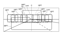
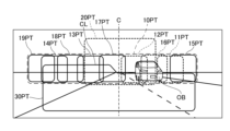
- FIG. 2 is a diagram showing a light distribution pattern formed by light emitted by the left vehicle headlight 1L in this embodiment.
- a low beam light distribution pattern 30PT is a light distribution pattern formed by light irradiated to the lower front side of the vehicle VE, and has a cut line CL which is the upper end of the low beam light distribution pattern 30PT.
- the first additional light distribution pattern 10PT is a light distribution pattern located at the upper end of the low beam light distribution pattern 30PT and in an area above the low beam light distribution pattern 30PT.
- the second additional light distribution pattern 20PT is a light distribution pattern that overlaps with a part of the first additional light distribution pattern 10PT, and is located in an area including the upper end of the low beam light distribution pattern 30PT and the central axis C of the low beam light distribution pattern 30PT in the left-right direction above the low beam light distribution pattern 30PT.
- the first additional light distribution pattern 10PT and the second additional light distribution pattern 20PT form a light distribution pattern of the additional high beam part.
- the light distribution pattern of this additional high beam part forms a high beam light distribution pattern by being added to the low beam light distribution pattern 30PT.
- the entire light distribution pattern shown in FIG. 2 is an example of a high beam light distribution pattern.
- the light distribution pattern is, for example, a light pattern drawn by light irradiated from each vehicle headlight 1L, 1R on a vertical surface located in front of the vehicle, and includes the light intensity distribution in addition to the outer shape of the light.
- the surface onto which the light from each vehicle headlight 1L, 1R is irradiated is, for example, located 25 m ahead of the vehicle.
- the vehicle headlamp 1L includes a low beam light source unit 30 that emits light forming a low beam light distribution pattern, a first light source unit 10 that emits light of a first additional light distribution pattern, a second light source unit 20 that emits light of a second additional light distribution pattern, a control unit 40, and a housing 50.
- the housing 50 includes a lamp housing 51 and a front cover 52 as main components.
- the front of the lamp housing 51 is open, and the front cover 52 is fixed to the lamp housing 51 so as to cover the opening.
- the low beam light source unit 30, the first light source unit 10, and the second light source unit 20 are accommodated in a space formed by the lamp housing 51 and the front cover 52 that covers the front opening of the lamp housing 51.
- the control unit 40 may or may not be arranged in the space of the housing 50.
- the low beam light source unit 30, the first light source unit 10, and the second light source unit 20 are accommodated in the space of the housing 50, but the low beam light source unit 30, the first light source unit 10, and the second light source unit 20 may each be accommodated in a different housing.
- the low beam light source unit 30 is, for example, a PES (Projector Ellipsoid System) type light source unit, and has a low beam light source section 30LS and a projection lens 30PL.
- the low beam light source section 30LS has, for example, a light emitting element, a reflector that reflects the light emitted from the light emitting element, and a shade.
- the light emitting element emits light, for example, upward, the reflector reflects the light toward the forward projection lens 30PL, and the shade cuts off part of the reflected light to form a cut line CL of the low beam light distribution pattern.
- the projection lens 30PL adjusts the divergence angle of the incident light and emits light that forms the low beam light distribution pattern 30PT.
- the low beam light source unit 30 is not limited to the PES type, and may be a direct type or a parabolic type.
- the low beam light source section 30LS has, for example, a light emitting element and a shade, and part of the light emitted from the light emitting element is cut by the shade, and the other light is incident on the projection lens 30PL.
- the low beam light source unit 30 is a parabolic type, the low beam light source unit 30 does not need to have a projection lens 30PL.
- the low beam light source unit 30 has a light emitting element and a reflector that reflects the light emitted from the light emitting element, and the reflector reflects the light so as to generate, for example, a cut line.
- the low beam light source unit 30 may have a configuration other than the above configuration, as long as it emits light of the low beam distribution pattern 30PT.
- the second light source unit 20 has a similar configuration to the low beam light source unit 30, for example, in that it does not have a portion that generates a cut line such as a shade, and in the example of FIG. 1, the second light source unit 20 has a second light source section 20LS and a projection lens 20PL.
- the optical design of the second light source unit 20 differs from that of the low beam light source unit 30 in that it emits light of the second additional light distribution pattern 20PT.
- the second light source unit 20 may have a different configuration from the low beam light source unit 30, so long as it emits light of the second additional light distribution pattern 20PT.
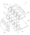
- FIG. 3 is an exploded perspective view of the first light source unit 10.
- the first light source unit 10 has a first light source section 10LS and a projection lens 10PL.
- the first light source section 10LS has an upper light source section 10U and a lower light source section 10L.
- the upper light source section 10U has a substrate 10UC and a plurality of light source sections 11-14 that are provided on the upper surface of the substrate 10UC and arranged side by side in the left-right direction.
- the light source section 11 has a light-emitting element 11L and a reflector 11R.
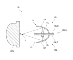
- Figure 4 is a cross-sectional view of the first light source unit 10. As shown in Figure 4, the light-emitting element 11L emits light upward, and the reflector 11R reflects the light from the light-emitting element 11L toward the projection lens 10PL. At this time, the light from the reflector 11R is focused at the focal point F of the projection lens 10PL. The reflective surface of the reflector 11R is formed so that the light propagates in this manner.
- the other light source sections 12-14 have light-emitting elements 12L-14L and reflectors 12R-14R, and are configured similarly to the light source section 11.
- the upper light source unit 10U includes multiple PES-type light sources including light-emitting elements 11L to 14L and reflectors 11R to 14R that cover the light-emitting elements 11L to 14L from above.
- the projection lens 10PL transmits the light emitted from the upper light source unit 10U.
- the lower light source unit 10L has a substrate 10LC and a plurality of light source units 15-19 arranged side by side in the left-right direction on the lower surface of the substrate 10UC.
- the light source unit 15 has a light-emitting element 15L and a reflector 15R. As shown in FIG. 4, the light-emitting element 15L emits light downward, and the reflector 15R reflects the light from the light-emitting element 15L toward the projection lens 10PL. At this time, the light from the reflector 15R is focused at the focal point F of the projection lens 10PL. The reflecting surface of the reflector 15R is formed so that the light propagates in this manner.
- the light source units 11-14 of the upper light source unit 10U and the light source units 15-19 of the lower light source unit 10L are offset in the left-right direction.
- the light source unit 19 is located at the leftmost position
- the light source unit 15 is located at the rightmost position.
- the light source units 11-14 of the upper light source unit 10U and the light source units 15-19 of the lower light source unit 10L are arranged alternately in the left-right direction with their positions offset in the up-down direction.
- the light-emitting element 14L is located between the light-emitting elements 19L and 18L in the left-right direction
- the light-emitting element 13L is located between the light-emitting elements 18L and 17L in the left-right direction
- the light-emitting element 12L is located between the light-emitting elements 17L and 16L in the left-right direction
- the light-emitting element 11L is located between the light-emitting elements 16L and 15L in the left-right direction.
- control unit 40 is electrically connected to the low beam light source unit 30LS of the low beam light source unit 30, the second light source unit 20LS of the second light source unit 20, and the first light source unit 10LS of the first light source unit 10.
- the control unit 40 is composed of, for example, a microcontroller, an integrated circuit such as an IC (Integrated Circuit), an LSI (Large-scale Integrated Circuit), or an ASIC (Application Specific Integrated Circuit), or an NC (Numerical Control) device.
- the control unit 40 may or may not use a machine learning device.
- the control unit 40 is also electrically connected to the ECU 3.
- the ECU 3 has a configuration similar to that of the control unit 40, for example, and supplies information to the vehicle headlights 1L and 1R.
- the ECU 3 may also perform engine control, airbag control, transmission control, etc.
- the detection device 4 has an image acquisition unit 4A and a judgment unit 4D, and is a device that detects objects such as pedestrians and other vehicles located in front of the vehicle VE. Other vehicles include vehicles in front and oncoming vehicles.
- the image acquisition unit 4A is composed of, for example, a LiDAR (Light Detection And Ranging) or a camera.
- the image acquisition unit 4A scans, for example, the front of the vehicle VE with a laser light, receives the laser light reflected back, generates a signal related to the image based on the received laser light, and outputs the signal to the judgment unit 4D.
- the image acquisition unit 4A When the image acquisition unit 4A is composed of a camera, examples of the camera include a CCD (Charged Coupled Device) camera and a CMOS (Complementary Metal Oxide Semiconductor) camera.
- the image acquisition unit 4A captures an image in front of the vehicle VE and outputs a signal related to the captured image to the judgment unit 4D.
- the determination unit 4D is electrically connected to the ECU 3 and has a configuration similar to that of the control unit 40, for example, and determines whether the image-related signal input from the image acquisition unit 4A contains an image of an object. If the image-related signal contains an image of an object, the determination unit 4D calculates the position coordinates of the object. If the image of the object is contained, the determination unit outputs a signal containing data related to the position coordinates of the object to the ECU 3.
- the light distribution pattern 11PT of the first additional light distribution pattern 10PT shown in FIG. 2 is a light distribution pattern due to the light emitted from the light source unit 11, and similarly, the light distribution patterns 12PT to 19PT are light distribution patterns due to the light emitted from the light source units 12 to 19, respectively.
- the center of the first additional light distribution pattern 10PT due to the light emitted from the first light source unit 10 of the vehicle headlamp 1L is shifted to the left of the central axis C in the left-right direction of the low beam light distribution pattern 30PT.
- light distribution patterns 11PT-14PT formed by light emitted from light source units 11-14 of upper light source unit 10U and transmitted through projection lens 10PL and light distribution patterns 15PT-19PT formed by light emitted from light source units 15-19 of lower light source unit 10L and transmitted through projection lens 10PL partially overlap in the left-right direction.
- light distribution patterns 11PT-19PT are arranged in the same manner as light source units 11-19 are arranged in the left-right direction.
- light distribution patterns 11PT-14PT formed by light emitted from light source units 11-14 of upper light source unit 10U and light distribution patterns 15PT-19PT formed by light emitted from light source units 15-19 of lower light source unit 10L are arranged alternately in the left-right direction while partially overlapping each other.
- light distribution patterns 11PT to 19PT are arranged alternately, so that light distribution patterns 11PT to 14PT formed by light emitted from the upper light source unit 10U are spaced apart in the left-right direction, and light distribution patterns 16PT to 18PT formed by light emitted from the lower light source unit 10L overlap at least a portion of the spaced light distribution patterns 11PT to 14PT formed by light emitted from the upper light source unit 10U and fill in the gaps between each of the spaced light distribution patterns 11PT to 14PT.
- the light distribution pattern of the light emitted from the lower light source unit 10L is positioned between the spaced light distribution patterns of the light emitted from the upper light source unit 10U, or the light distribution pattern of the light emitted from the upper light source unit 10U is positioned between the spaced light distribution patterns of the light emitted from the lower light source unit 10L, thereby making it possible to brighten positions other than the left-right ends of the first additional light distribution pattern 10PT.
- the light distribution pattern 14PT located on the left-right end side of the first additional light distribution pattern 10PT with respect to the central axis C of the low beam light distribution pattern 30PT is defined as the predetermined light distribution pattern 14PT
- the light source unit that emits light forming the predetermined light distribution pattern 14PT is defined as the predetermined light source unit 14
- the light-emitting element of the predetermined light source unit 14 is defined as the predetermined light-emitting element 14L.
- the predetermined light distribution pattern 14PT overlaps in the left-right direction with the light distribution patterns 19PT, 18PT formed by the light emitted by the light-emitting elements 19L, 18L other than the predetermined light-emitting element 14L.
- the predetermined light distribution pattern is light distribution pattern 18PT or light distribution pattern 16PT
- the specific light distribution pattern is light distribution pattern 17PT, light distribution pattern 13PT, or light distribution pattern 12PT. That is, in the case of the first additional light distribution pattern 10PT of this embodiment, the amount of overlap between a predetermined light distribution pattern located on the left and right end sides of the first additional light distribution pattern 10PT and a light distribution pattern due to light emitted by some of the light-emitting elements other than the predetermined light-emitting element is greater than the amount of overlap between a specific light distribution pattern located closer to the central axis C than the predetermined light distribution pattern and a light distribution pattern due to light emitted by some of the light-emitting elements other than the specific light-emitting element. Therefore, the area of the specific light distribution pattern can be brighter than the area of the predetermined light distribution pattern.
- the predetermined light distribution pattern is light distribution pattern 14PT and the specific light distribution pattern is light distribution pattern 17PT or light distribution pattern 13PT
- the predetermined light distribution pattern 14PT does not overlap with the second additional light distribution pattern 20PT
- the specific light distribution patterns 17PT and 13PT overlap with the second additional light distribution pattern 20PT.
- the second additional light distribution pattern 20PT overlaps with at least a portion of the specific light distribution patterns 17PT and 13PT and does not overlap with the predetermined light distribution pattern 14PT
- the second additional light distribution pattern 20PT can brighten the specific light distribution patterns 17PT and 13PT, which may be darker than the predetermined light distribution pattern 14PT.
- the predetermined light distribution pattern is light distribution pattern 16PT
- both the predetermined light distribution pattern 16PT and the specific light distribution patterns 12PT and 17PT overlap with the second additional light distribution pattern 20PT.
- the second additional light distribution pattern 20PT is preferably formed in an area above the first additional light distribution pattern 10PT, in addition to an area overlapping with the first additional light distribution pattern 10PT. In this case, it is possible to brighten a marker lamp installed at a high position in front of the vehicle.
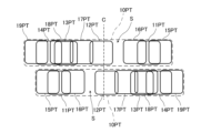
- FIG. 5 is a diagram showing the relationship between the first additional light distribution pattern 10PT emitted from the left and right vehicle headlights 1L, 1R. Note that in this diagram, to avoid complicating the diagram, the first additional light distribution pattern 10PT emitted from the left vehicle headlight 1L is drawn above the first additional light distribution pattern 10PT emitted from the right vehicle headlight 1R, but the first additional light distribution pattern 10PT emitted from the left vehicle headlight 1L and the first additional light distribution pattern 10PT emitted from the right vehicle headlight 1R are formed at approximately the same height.
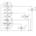
- Step S1 This step is a step in which the next step is different depending on whether an on signal is input from a light switch (not shown).
- the control unit 40 advances the control flow to step S2 if an on signal is not input from the light switch, and advances the control flow to step S3 if an on signal is input.
- the on signal from the light switch may be input to the control unit 40 directly or via the ECU 3.
- Step S4 This step is a step in which the next step is different depending on whether an on signal is input from a high beam switch (not shown).
- the control unit 40 advances the control flow to step S5 if an on signal is not input from the high beam switch, and advances the control flow to step S6 if an on signal is input from the high beam switch.
- the on signal from the high beam switch may be input to the control unit 40 directly or via the ECU 3.
- Step S8 This step is a step in which the next step is different depending on whether or not the object is located at a position overlapping with the second additional light distribution pattern 20PT.
- a signal including data related to the position coordinates of the object is input to the control unit 40 from the detection device 4. Therefore, when the coordinates of the object are located at a position overlapping with the second additional light distribution pattern 20PT, the control unit 40 advances the control flow to step S9, and when the coordinates of the object are not located at a position overlapping with the second additional light distribution pattern 20PT, the control unit 40 advances the control flow to step S10.
- Step S9 This step is a step of putting the vehicle headlamp 1L into a first dimming state.
- the first dimming state the light forming the second additional light distribution pattern 20PT is dimmed or turned off, and the light forming the light distribution pattern overlapping the object in the first additional light distribution pattern 10PT is dimmed or turned off.
- FIG. 7 is a diagram showing a light distribution pattern in the first dimming state.
- the control unit 40 controls the second light source unit 20LS of the second light source unit 20 to dim or turn off the second light source unit 20LS, and controls the first light source unit 10LS of the first light source unit 10 to dim or turn off the light source unit forming the light distribution pattern overlapping the object OB.
- the object OB is an oncoming vehicle, and the position of the object OB overlaps with the light distribution patterns 12PT, 16PT, and 11PT formed by the light from the light source units 12, 16, and 11. Therefore, the control unit 40 dims or turns off the light emitting elements 12L, 16L, and 11L of the light source unit 12.
- the position where the light distribution patterns of the light emitted from each of the light source sections located on the upper and lower sides overlap in the left-right direction can be set to a desired position. Therefore, according to this vehicle headlamp 1L, 1R, it is possible to brighten a desired position in the left-right direction in the first additional light distribution pattern 10PT above the low-beam light distribution pattern 30PT.
- the vehicle headlamps 1L, 1R of this embodiment also include a second light source unit 20 that emits light that overlaps with a portion of the first additional light distribution pattern 10PT and forms a second additional light distribution pattern 20PT in an area including the central axis C at the upper end of the low beam light distribution pattern 30PT and above the low beam light distribution pattern 30PT.
- the second additional light distribution pattern 20PT can be part of the light distribution pattern of the additional high beam portion together with the first additional light distribution pattern 10PT, and can brighten the upper area including the central axis C in the left-right direction of the low beam light distribution pattern 30PT.
- the vehicle headlamp set 1 of this embodiment also includes a vehicle headlamp 1L arranged on the left side of the vehicle VE and a vehicle headlamp 1R arranged on the right side of the vehicle VE, and the first additional light distribution pattern 10PT formed by the light emitted by the left vehicle headlamp 1L and the first additional light distribution pattern 10PT formed by the light emitted by the right vehicle headlamp 1R overlap with each other. Therefore, the left and right vehicle headlamp 1L, 1R can make the first additional light distribution pattern 10PT brighter than the overlapping area.
Landscapes
- Engineering & Computer Science (AREA)
- General Engineering & Computer Science (AREA)
- Physics & Mathematics (AREA)
- Microelectronics & Electronic Packaging (AREA)
- Optics & Photonics (AREA)
- Non-Portable Lighting Devices Or Systems Thereof (AREA)
Abstract
L'invention concerne un phare de véhicule (1L), (1R) comprenant une unité de source de lumière de feu de croisement (30), et une première unité de source de lumière (10) qui émet de la lumière formant un premier motif de distribution de lumière supplémentaire (10 PT) dans une région comprenant l'extrémité supérieure d'un motif de distribution de lumière de feu de croisement et son côté supérieur. La première unité de source de lumière (10) comprend : une unité de source de lumière supérieure (10U) dans laquelle une pluralité de parties de source de lumière (11)- (14) sont disposées côte à côte, et des motifs de distribution de lumière (11 PT)- (14 PT) formés par la lumière émise par les parties de source de lumière (11)- (14) sont alignés dans la direction gauche-droite ; et une unité de source de lumière inférieure (10L) qui est disposée au-dessous de l'unité de source de lumière supérieure (10U), et dans laquelle une pluralité de parties de source de lumière (15) à (19) sont disposées côte à côte et des motifs de distribution de lumière (15 PT)- (19 PT) formés par la lumière émise par les parties de source de lumière (15)- (19) sont alignés dans la direction gauche-droite. Les motifs de distribution de lumière (11 PT)- (14 PT) et les motifs de distribution de lumière (15 PT)- (19 PT) se chevauchent dans la direction gauche-droite.
Priority Applications (1)
| Application Number | Priority Date | Filing Date | Title |
|---|---|---|---|
| JP2025529698A JPWO2025004954A1 (fr) | 2023-06-27 | 2024-06-20 |
Applications Claiming Priority (2)
| Application Number | Priority Date | Filing Date | Title |
|---|---|---|---|
| JP2023105297 | 2023-06-27 | ||
| JP2023-105297 | 2023-06-27 |
Publications (1)
| Publication Number | Publication Date |
|---|---|
| WO2025004954A1 true WO2025004954A1 (fr) | 2025-01-02 |
Family
ID=93938453
Family Applications (1)
| Application Number | Title | Priority Date | Filing Date |
|---|---|---|---|
| PCT/JP2024/022365 Ceased WO2025004954A1 (fr) | 2023-06-27 | 2024-06-20 | Phare de véhicule |
Country Status (2)
| Country | Link |
|---|---|
| JP (1) | JPWO2025004954A1 (fr) |
| WO (1) | WO2025004954A1 (fr) |
Citations (1)
| Publication number | Priority date | Publication date | Assignee | Title |
|---|---|---|---|---|
| JP2011020559A (ja) * | 2009-07-15 | 2011-02-03 | Koito Mfg Co Ltd | 車両用前照灯装置 |
-
2024
- 2024-06-20 WO PCT/JP2024/022365 patent/WO2025004954A1/fr not_active Ceased
- 2024-06-20 JP JP2025529698A patent/JPWO2025004954A1/ja active Pending
Patent Citations (1)
| Publication number | Priority date | Publication date | Assignee | Title |
|---|---|---|---|---|
| JP2011020559A (ja) * | 2009-07-15 | 2011-02-03 | Koito Mfg Co Ltd | 車両用前照灯装置 |
Also Published As
| Publication number | Publication date |
|---|---|
| JPWO2025004954A1 (fr) | 2025-01-02 |
Similar Documents
| Publication | Publication Date | Title |
|---|---|---|
| US10895357B2 (en) | Vehicle lamp | |
| JP7140559B2 (ja) | 車両用ランプ | |
| CN115362086B (zh) | 车辆用前照灯 | |
| US7510310B2 (en) | Vehicle lighting device | |
| EP2103867B1 (fr) | Appareil de phare de véhicule | |
| JP7201425B2 (ja) | 車両用灯具システム、車両用灯具の制御装置および車両用灯具の制御方法 | |
| JP5199798B2 (ja) | 車両用前照灯装置 | |
| JP6889588B2 (ja) | 車両用灯具 | |
| US20070041207A1 (en) | Vehicle lamp | |
| US20120140503A1 (en) | Head Lamp for Vehicle | |
| JP7487822B2 (ja) | 車両用灯具 | |
| US20170232882A1 (en) | Vehicle lamp | |
| JPWO2019021914A1 (ja) | 灯具ユニットおよび車両用前照灯 | |
| JP7289388B2 (ja) | 光学ユニット | |
| WO2025004953A1 (fr) | Phare pour véhicule, et ensemble de phares pour véhicule | |
| US20250222856A1 (en) | Vehicle headlamp | |
| WO2024142734A1 (fr) | Phare de véhicule | |
| WO2025004954A1 (fr) | Phare de véhicule | |
| JP2021195014A (ja) | 車両用灯具 | |
| JP7542051B2 (ja) | 車両用前照灯 | |
| WO2024214471A1 (fr) | Phare de véhicule | |
| US12066161B2 (en) | Vehicle headlamps | |
| WO2025182833A1 (fr) | Phare de véhicule | |
| WO2026079131A1 (fr) | Phare de véhicule | |
| US20250381907A1 (en) | Vehicular headlamp |
Legal Events
| Date | Code | Title | Description |
|---|---|---|---|
| 121 | Ep: the epo has been informed by wipo that ep was designated in this application |
Ref document number: 24831816 Country of ref document: EP Kind code of ref document: A1 |
|
| ENP | Entry into the national phase |
Ref document number: 2025529698 Country of ref document: JP Kind code of ref document: A |
|
| WWE | Wipo information: entry into national phase |
Ref document number: 2025529698 Country of ref document: JP |
|
| NENP | Non-entry into the national phase |
Ref country code: DE |