WO2025005016A1 - Dispositif de transport et de distribution de médicaments - Google Patents
Dispositif de transport et de distribution de médicaments Download PDFInfo
- Publication number
- WO2025005016A1 WO2025005016A1 PCT/JP2024/022658 JP2024022658W WO2025005016A1 WO 2025005016 A1 WO2025005016 A1 WO 2025005016A1 JP 2024022658 W JP2024022658 W JP 2024022658W WO 2025005016 A1 WO2025005016 A1 WO 2025005016A1
- Authority
- WO
- WIPO (PCT)
- Prior art keywords
- cassette
- dispensing device
- tablet
- unit
- transport
- Prior art date
- Legal status (The legal status is an assumption and is not a legal conclusion. Google has not performed a legal analysis and makes no representation as to the accuracy of the status listed.)
- Ceased
Links
Images













Classifications
-
- A—HUMAN NECESSITIES
- A61—MEDICAL OR VETERINARY SCIENCE; HYGIENE
- A61J—CONTAINERS SPECIALLY ADAPTED FOR MEDICAL OR PHARMACEUTICAL PURPOSES; DEVICES OR METHODS SPECIALLY ADAPTED FOR BRINGING PHARMACEUTICAL PRODUCTS INTO PARTICULAR PHYSICAL OR ADMINISTERING FORMS; DEVICES FOR ADMINISTERING FOOD OR MEDICINES ORALLY; BABY COMFORTERS; DEVICES FOR RECEIVING SPITTLE
- A61J3/00—Devices or methods specially adapted for bringing pharmaceutical products into particular physical or administering forms
-
- B—PERFORMING OPERATIONS; TRANSPORTING
- B65—CONVEYING; PACKING; STORING; HANDLING THIN OR FILAMENTARY MATERIAL
- B65B—MACHINES, APPARATUS OR DEVICES FOR, OR METHODS OF, PACKAGING ARTICLES OR MATERIALS; UNPACKING
- B65B1/00—Packaging fluent solid material, e.g. powders, granular or loose fibrous material, loose masses of small articles, in individual containers or receptacles, e.g. bags, sacks, boxes, cartons, cans, or jars
- B65B1/30—Devices or methods for controlling or determining the quantity or quality or the material fed or filled
Definitions
- the present invention relates to a drug delivery and dispensing device that includes a tablet packaging machine equipped with a cassette and a transport unit that grasps and moves the cassette.
- Tablet packaging machines are widely known, which include a cassette for storing tablets therein and a packaging device for packaging tablets dispensed one by one from the cassette in accordance with prescription data.
- a tablet packaging machine is used by an operator replacing cassettes or refilling the cassettes with tablets.
- a fully automatic tablet packaging machine equipped with a storage shelf for storing a large number of cassettes and a mechanism for dispensing tablets from the storage shelf has also been considered as one type of such device (see, for example, Patent Document 1, etc.).
- a fully automatic powder medicine packaging machine that moves a cassette used for powder medicine stored in a storage section to a position where it can be dispensed and then dispenses the medicine (see, for example, Patent Documents 2 and 3).
- a fully automatic tablet dispensing machine it is advantageous to store many cassettes in the storage shelves so that it can handle a variety of prescriptions, but on the other hand, it is not preferable to make it possible to dispense tablets from cassettes placed in all storage shelves, as this would lead to a complicated drop path to the packaging device and would increase the cost of the entire machine.
- a fully automatic tablet packaging machine equipped with a conveying means for moving the cassette itself has also been considered (see, for example, Patent Documents 4 and 5).
- the present invention has a transport unit capable of gripping and transporting a cassette containing medicine, a first storage shelf capable of storing a plurality of cassettes by attaching them to a cassette base and capable of dispensing the medicine from the stored cassette, a second storage shelf capable of storing a plurality of cassettes, a packaging device for packaging the medicine dispensed from the first storage shelf, and a medicine transport path connecting the first storage shelf and the packaging device, and is characterized in that the packaging device, the first storage shelf, and the second storage shelf are arranged in the stated order along the movable direction of the transport unit.
- the present invention provides a new type of drug delivery and dispensing device that ensures a sufficient number of cassettes can be stored while simplifying the tablet dispensing mechanism.
- FIG. 2 is a diagram showing an example of the configuration of a medicine delivering and dispensing device.
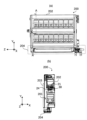
- FIG. 2 is a side view showing an example of the configuration of the medicine transporting and dispensing device shown in FIG. 1 .
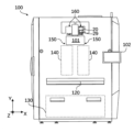
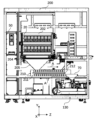
- FIG. 2 is a front view showing an example of the configuration of a medicine delivering and dispensing device.
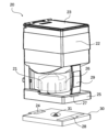
- FIG. 2 is a diagram showing an example of the configuration of a cassette mounted on the medicine delivery and dispensing device.
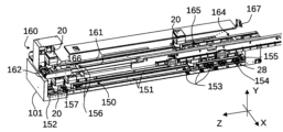
- 1 is a diagram illustrating an example of the configuration of an incoming transport unit and an outgoing transport unit that perform incoming and outgoing transport of cassettes.
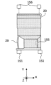
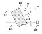
- FIG. 13A and 13B are diagrams illustrating an example of a cassette receiving operation in the receiving transport section.
- FIGS. 13A and 13B are diagrams illustrating another example of the storing operation of the cassette in the storing transport section.
- FIG. 7 is a diagram showing an example of a failure in the storing operation shown in FIG. 6 .
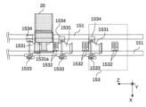
- 13 is a diagram showing an example of the configuration of a gap adjustment unit for adjusting the gap between cassettes to be stored;
- FIG. 10A to 10C are diagrams illustrating an example of the operation of the interval adjustment unit illustrated in FIG. 9 .
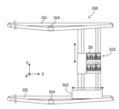
- FIG. 2 is a diagram illustrating an example of a configuration of a transport unit for transporting a cassette.
- 13A and 13B are diagrams illustrating an example of a configuration for gripping a cassette in a transport section.
- FIG. 11A and 11B are diagrams illustrating an example of the configuration of a claw portion and a posture stabilizing member in the present embodiment.
- 14A to 14C are diagrams illustrating schematic diagrams showing positional relationships and forces acting when a cassette is gripped by each part shown in FIG. 13 .
- FIG. 4 is a diagram showing an example of a configuration of a second storage shelf according to the present invention.
- FIG. 2 is a diagram showing an example of a configuration of a first storage shelf according to the present invention.
- 13 is a diagram showing an example of the configuration of a transport path for transporting medicines from a second storage shelf to a packaging device.
- FIG. FIG. 1 is a diagram showing an example of a configuration of a packaging device according to the present invention.
- FIG. 1 is a diagram showing an example of individually packaged medicine.
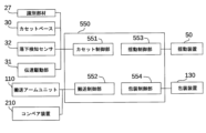
- FIG. 2 is a diagram showing an example of the configuration of a control unit of the medicine transport and dispensing device.
- 7A to 7C are diagrams illustrating an example of a control operation of a conveying unit according to the present invention.
- 13A and 13B are diagrams illustrating a modified example of a space adjustment unit for adjusting the space between cassettes to be stored.
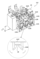
- FIG. 1 is a diagram showing an example of a configuration of a rocking device according to the present invention.
- 1A to 1C are diagrams illustrating an example of a shaking operation of the rocking device of the present invention.
- 11A and 11B are diagrams illustrating an example of a lid pressing mechanism of the rocking device.
- FIG. 26A to 26C are diagrams illustrating an example of the operation of the lid pressing mechanism illustrated in FIG. 25.
- 1 is a diagram showing an example of a configuration of a cassette placement section of the present invention
- FIG. 13 is a diagram showing a comparative example of a fall path.
- FIG. 2 is a diagram showing the falling path of a jammed tablet in the present invention.
- 11A and 11B are diagrams illustrating an example of a control method when performing a shaking operation in a rocking device.
- FIG. 13 is a diagram showing an example of removing jammed tablets using a rocking device.
- FIG. 13 is a diagram showing an example of clearing a jammed tablet when the rocking device is tilted 90 degrees.
- FIG. 13 is a diagram showing an example of clearing a jammed tablet when the rocking device is tilted at 135 degrees.
- FIG. 1 shows a perspective view of a medicine delivery and dispensing device 500 as an embodiment of the present invention, as viewed from the upper right direction.
- the medicine delivery and dispensing device 500 is a series of units that are connected and arranged in a line, in order from the +Z direction side, which is the front side where the operator stands, to the -Z direction side, a front unit 100 having a packaging device 130 at the bottom, a collector shelf 200 that is a first storage shelf capable of storing a plurality of tablet cassettes 20 and dispensing tablets from the tablet cassettes 20, a storage shelf 300 that is a second storage shelf on which the tablet cassettes 20 can be placed, and a power unit 400 that powers the electrical system.
- the medicine delivery and dispensing device 500 also has a control unit 550 as a central computing unit for controlling each part.
- the control unit 550 may be located anywhere inside the medicine delivery and dispensing device 500, but in this embodiment, the control unit 550 is described as being located at the top of the main body of the medicine delivery and dispensing device 500.
- a configuration is described in which a collector shelf 200 and a storage shelf 300 are provided in pair on each side, but multiple collector shelves 200 and multiple storage shelves 300 may be provided.
- the medicine delivering and dispensing device 500 stores therein a plurality of tablet cassettes 20 for dispensing medicines, and has a transport arm unit 110 which is a transport section capable of gripping and transporting the tablet cassette 20.
- the transport arm units 110 are arranged in a pair, one on each side of the drug transport and dispensing device 500, and each moves independently of the other in the ⁇ Z and ⁇ Y directions outside the collector shelf 200 and the storage shelf 300, thereby functioning as a transport means that allows tablet cassettes 20 to be transferred between the collector shelf 200, the storage shelf 300 and the front unit 100.
- the transport arm unit 110 has a catcher unit 112 that operates along a rail unit 111, which is an endless belt stretched in a pair above and below in the Z direction, and in the vertical Y direction, the catcher unit 112 moves a grip unit 113 up and down, allowing the transport arm unit 110 to move freely in the YZ plane.
- an intermediate gear 114 is fixed to the housing in the middle of the rail unit 111, and by pressing the rail unit 111 in the X direction opposite the side where the catcher unit 112 abuts, tension is maintained so that the rail unit 111 extends linearly along the Z direction.
- the transport arm unit 110 is disposed so as to include at least the collector shelf 200 and the storage shelf 300 within its movable range, with the movable direction being a straight line in the Z direction including an extension of the rail unit 111. Furthermore, as will be described later, the incoming storage unit 154 and the outgoing storage unit 164, which are located on the -Z direction side of the front unit 100, are also located within the movable range of the transport arm unit 110.
- the front unit 100 has a manual distribution section 120 provided for an operator to manually distribute medicine, a packaging device 130 located at the bottom, and a storage section 140 for storing large-capacity cassettes 40.
- the front unit 100 has an incoming transport section 150 for storing the tablet cassette 20 inside the front unit 100, and an outgoing transport section 160 for discharging the tablet cassette 20 from the front of the front unit 100.
- the incoming and outgoing conveying sections 150 and 160 are each provided symmetrically in a pair at positions that are linearly symmetrical about the center line of the front unit 100, and a partition wall 101 is provided at the end of the incoming and outgoing conveying section 150 in the +Z direction to prevent the tablet cassettes 20 placed on them from falling forward.
- the front unit 100 is provided with a touch panel monitor 102, which can be used to check the operating status of the drug delivery and dispensing device 500 and to operate it.
- the monitor 102 can be used as both an operating means and a display means for the drug delivery and dispensing device 500.
- the tablet cassette 20 is a medicine containing container that includes a rotor 21 , a container body 22 for containing tablets, a handle portion 29 , a lid portion 23 , and a tablet discharge port 24 .
- the base portion 25 of the tablet cassette 20 is fitted into a cassette base 30 provided in plurality on the collector shelf 200, whereby the rotor 21 can be rotated and the tablets contained therein can be discharged one by one from the tablet discharge port 24.
- the handle portion 29 is a curved, thin-plate-like handle, and an operator can easily carry the tablet cassette 20 by gripping the handle portion 29 .
- the cassette base 30 has a transmission drive unit 31 that transmits driving force by engaging with the lower part of the rotor 21 of the tablet cassette 20 from below, and when this transmission drive unit 31 is rotated by a pulse motor, the rotor 21 also rotates in sync. At this time, a large number of wing-shaped partitions 26 are formed at equal pitch on the outer peripheral surface of the rotor 21, and the tablets line up and enter each compartment separated by these partitions 26, so that the tablets are discharged one by one from the tablet discharge port 24 as the rotor 21 rotates.
- the space separated by rotor 21 and partition 26 functions as an alignment plate, and when rotor 21 is rotated on its axis, partition 26 rotates on its axis in accompaniment, thereby enabling tablets to be sequentially discharged from main body 22 of tablet cassette 20.
- An identification member 27 for identifying the type of tablets stored therein is attached to the base 25 of the tablet cassette 20.
- a commercially available thin and flexible RFID tag (Radio Frequency Identifier) is adopted as the identification member 27, and identification information assigned to each tablet cassette 20 is written in advance and stored as data.
- An identification member sensor 28 is provided on the cassette base 30 side for recognizing the identification member 27 on its upper surface 33, and this configuration makes it possible to identify the tablet cassette 20 fitted in the cassette base 30.
- the control unit 550 stores the combination of the identification member 27 of the tablet cassette 20 and the medicine stored in the tablet cassette 20, and the information can be confirmed via the monitor 102, for example.
- FIG. 5 shows a part of the configuration of the incoming transport section 150 and the outgoing transport section 160 of the front unit 100 shown in FIG. 3.
- the incoming transport section 150 and the outgoing transport section 160 are both provided symmetrically on the front unit 100, but because their structures are similar, the incoming transport section 150 and the outgoing transport section 160 arranged on the +X direction side will be described in particular.
- the outgoing conveying section 160 is attached above the front unit 100 and functions as a belt-type conveying means composed of an outgoing conveying belt 161, which is two endless belts wound along the -Z direction, and a drive roller 162 for driving the outgoing conveying belt 161.
- the outgoing conveying section 160 is capable of moving the tablet cassette 20 placed on the outgoing conveying belt 161 in the +Z direction by rotating the outgoing conveying belt 161 .
- the outgoing conveying section 160 has an outgoing storage section 164, which is a loading area provided at the end of the outgoing conveying belt 161 on the -Z direction upstream side in the conveying direction, an outgoing management sensor 165, and an end position detection sensor 166 attached to the rear end of the outgoing conveying belt 161.
- the outgoing management sensor 165 detects the presence of the tablet cassette 20, and the outgoing conveying belt 161 is rotated in the +Z direction to convey the tablet cassette 20. In this manner, the delivery storage section 164 is provided within the movable range of the catcher unit 112 .
- the output management sensor 165 is a light detection sensor in which the optical axis of the irradiated light is adjusted so as to diagonally cross the output storage section 164.
- the irradiated light is reflected by a reflector 167 provided opposite to the output storage section 164 and returns to the output management sensor 165.
- the tablet cassette 20 blocks the irradiated light somewhere on the optical path, so that the irradiated light cannot be detected, and it can be detected that the tablet cassette 20 is located in the output storage section 164.
- the delivery management sensor 165 uses an optical detection sensor that is paired with a reflector 167, but is not limited to this configuration and other existing detection means may be used.
- the terminal position detection sensor 166 detects the tablet cassette 20 directly above and stops the operation of the outgoing conveying belt 161. 1 and 2, the terminal end portion of the outgoing conveying section 160 protrudes forward in the +Z direction from the front unit 100, so that the operator can remove the tablet cassette 20 placed at this terminal end position. In this manner, the terminal end position is the outgoing position when the tablet cassette 20 is discharged from the outgoing conveying section 160, and the terminal end position detection sensor 166 operates as an outgoing detection section that detects that the tablet cassette 20 has reached the outgoing position.
- the incoming transport section 150 functions as a belt-type transport means composed of an incoming transport belt 151, which is two endless belts wrapped around the rear side of the partition wall 101 in the -Z direction, and a drive roller 152 for driving the incoming transport belt 151.
- a tablet cassette 20 can be placed on the upstream end of the incoming conveyor belt 151 in the direction of rotation, and an incoming detection sensor 157, which is an optical sensor, is provided as detection means for detecting whether a tablet cassette 20 is placed at this upstream end position.
- the incoming detection sensor 157 is provided in such a manner that it directs emitted light diagonally upward so that it is reflected by a reflector plate (not shown) located near the drive roller 162. With this configuration, when the emitted light from the incoming detection sensor 157 is blocked by the tablet cassette 20 or the like, the incoming detection sensor 157 detects that a tablet cassette 20 has been placed at the upstream end position.
- the incoming transport section 150 rotates the incoming transport belt 151, thereby moving the tablet cassette 20 placed on the incoming transport belt 151 in the -Z direction.
- the operator places the tablet cassette 20 to be stored on the incoming transport belt 151 behind the partition wall 101, and moves the tablet cassette 20 into the medicine transport and dispensing device 500.
- three spacing adjustment means 153 are provided downstream in the movement direction of the incoming transport section 150, i.e., on the -Z direction side.
- the movement is restricted by the spacing adjustment means 153, thereby appropriately adjusting the spacing between two adjacent tablet cassettes 20.
- the specific operation and configuration of the spacing adjustment means 153 will be described later.
- the number of spacing adjustment means 153 provided is arbitrary, but it is preferable that there be more than one.
- An input/output storage section 154 for arranging and arranging the tablet cassettes 20 is provided on the -Z direction side of the interval adjustment means 153. Since the input/output storage section 154 is within the movable range of the transport arm unit 110, the tablet cassettes 20 that have reached the input/output storage section 154 are held by the transport arm unit 110 in a state in which they can be transported to the collector shelf 200, the storage shelf 300, or any other location in the medicine transporting and dispensing device 500.
- An identification member sensor 28 for recognizing the identification member 27 of the tablet cassette 20 is provided below the receiving storage section 154, and the identification information of the tablet cassette 20 moved to the receiving storage section 154 is stored in the control section 550. Note that the receiving storage section 154 may be provided with a plurality of identification member sensors 28, for example, four.
- a first direction detection sensor 155 is disposed in the receiving storage section 154 along the receiving conveyor belt 151 in the Z direction.
- the first direction detection sensor 155 is a laser-type detection means that is passed in the +Z direction as shown in Figure 6, and the light emitted from the first direction detection sensor 155 passes through the gaps in the tablet cassettes 20, in this case the space between the handle portion 29 and the main body of the tablet cassette 20, making it possible to detect that each tablet cassette 20 placed on the input/output transport section 150 is placed in the correct orientation.
- Also disposed above the incoming transport section 150 are second direction detection sensors 156 for detecting whether or not both ends of the tablet cassette 20 are positioned directly above the incoming transport belt 151 .
- the second direction detection sensor 156 is a laser-type detection means that is arranged at both ends of the transport path of the input transport section 150 and passes directly downward, and when the tablet cassette 20 passes directly below it, if both sensors detect its passage at the same time (both are ON), it can detect that the tablet cassette 20 is moving perpendicular to the transport direction as shown in Figure 6. Conversely, as shown in Figure 7, if the tablet is placed incorrectly, the light emitted by the first direction detection sensor 155 is blocked by the tablet cassette 20 and turns OFF, making it possible to detect the incorrect placement direction.
- the first direction detection sensor 155 is likely to turn OFF because it is blocked by the tablet cassette 20.
- the first direction detection sensor 155 happens to be tilted only to the extent that it can pass, by arranging a pair of second direction detection sensors 156 on both sides of the incoming conveyor belt 151, it is possible to determine whether or not the tablet cassette 20 is moving parallel to the conveyor direction based on whether or not each of the second direction detection sensors 156 turns ON within a predetermined time interval.
- FIG. 8 is a schematic example of a case where the inclination with respect to the transport direction is large, in reality, the difference in timing at which the two second direction detection sensors 156 are blocked may not be as large as the inclination shown in the figure.
- first direction detection sensor 155 or second direction detection sensor 156 will be turned OFF, detecting that tablet cassette 20 is not being conveyed in the correct posture. Conversely, when both the first direction detection sensor 155 and the second direction detection sensor 156 are ON, the control unit 550 determines that the tablet cassette 20 placed on the incoming conveyor belt 151 is placed in the correct position.
- the transport arm units 110 are arranged on both sides of the drug transport/dispensing device 500 with their respective grip units 113 facing inward, so that the tablet cassette 20 is transported to the receiving/storage section 154 in the correct position with the handle portion 29 facing outward in the receiving/transporting section 150, allowing the grip unit 113 to grasp and move the handle portion 29 of the tablet cassette 20.
- a sufficient gap is required for the grip unit 113 of the transport arm unit 110 to enter the tablet cassettes 20 placed side by side in the receiving and storing section 154 . Therefore, in this embodiment, there is provided a gap adjustment means 153 for adjusting such a gap while the input conveyor belt 151 conveys the tablet cassette 20.
- the gap adjustment means 153 has an L-shaped plate-like member 1531 which is a regulating means for regulating movement of the tablet cassette 20 in the -Z direction by abutting against the base 25 of the tablet cassette 20, and a gap adjustment sensor 1532 which is a gap adjustment detection unit for detecting that the tablet cassette 20 has reached a predetermined position.
- Multiple spacing adjustment means 153 are arranged side by side in the Z direction between the two input conveying belts 151, and as the tablet cassette 20 passes above each of them, each spacing adjustment means 153 operates to adjust the spacing of the tablet cassette 20 before it reaches the input storage section 154 downstream.
- the plate-like member 1531 is an L-shaped plate-like member supported so as to rotate about a rotation axis 1533 aligned in the X direction.
- the drive source 1534 rotates the plate-like member 1531 about the rotation axis 1533, so that a tip end 1531a of the plate-like member 1531 enters the tablet cassette 20 and abuts against the base portion 25, which is the bottom surface of the tablet cassette 20.
- the tablet cassette 20 since the incoming conveyor belt 151 continues to rotate, the tablet cassette 20 tries to be conveyed in the -Z direction, but the leading end 1531a abuts against the bottom surface and gets caught, thereby restricting the conveyance of the tablet cassette 20.
- FIG. 10 shows a schematic diagram of the operation of the distance adjusting means 153.
- a plurality of tablet cassettes that are transported side by side will be described separately as tablet cassettes 20a, 20b, and 20c.
- tablet cassettes 20a, 20b, and 20c are packed tightly together without any adjustment of the gaps on the incoming conveyor belt 151.
- the gap adjustment sensor 1532 detects the passage of the first tablet cassette 20a
- the plate-like member 1531 rotates a predetermined time after the tablet cassette 20a has passed and comes into contact with the bottom surface of tablet cassette 20b.
- the tablet cassette 20a Since the input conveying belt 151 continues to be driven, as shown in Figure 10 (b), the tablet cassette 20a will move forward for the period of time that the tip end 1531a abuts and gets caught on the bottom surface of the tablet cassette 20b, and in this way the distance La between tablet cassette 20a and tablet cassette 20b can be adjusted by the contact time of the plate-shaped member 1531.
- the plate-like member 1531 is L-shaped and is shaped to abut by fitting into a recess in the bottom surface of the tablet cassette 20, but this configuration is not limited to this and any structure can be used as long as it is capable of restricting and temporarily stopping the transport by the input conveyor belt 151 by abutting against the tablet cassette 20.
- the abutting state is released again by the rotation of the plate-like member 1531 as shown in FIG. 10(c), and the tablet cassette 20b moves with the gap La remaining opened.
- the gap adjustment sensor 1532 detects that the tablet cassette 20b has reached a predetermined position
- the plate-like member 1531 similarly rotates a predetermined time after the tablet cassette 20c has passed and abuts against the bottom surface of the tablet cassette 20b.
- each of the multiple lined up plate-like members 1531 may be rotated and inserted into the bottom surfaces of the tablet cassettes 20a, 20b, and 20c as shown in FIG. 10(e).
- the plate-shaped member 1531 inserted into each of the tablet cassettes 20a, 20b, 20c in this manner when the input conveying belt 151 rotates, the conveying of the tablet cassette 20 is restricted as shown in Figure 10 (f) when the side wall upstream in the conveying direction at the bottom of each of the tablet cassettes 20a, 20b, 20c abuts against the tip portion 1531a of the plate-shaped member 1531.
- the spacing La, Lb between the tablet cassettes 20a, 20b, 20c is automatically adjusted to a predetermined spacing L1 based on the spacing L2 between the tip ends 1531a when the plate-shaped members 1531 rotate and the width of the tablet cassette 20.
- multiple spacing adjustment means 153 to regulate the movement of multiple lined up tablet cassettes 20 in the conveying direction, it is possible to automatically adjust the spacing between each tablet cassette 20 without being affected by the drive timing or control of the plate-shaped member 1531.
- the aligned tablet cassettes 20 are transported to the inventory storage section 154 located downstream of the interval adjustment means 153 in the transport direction while maintaining the interval L1 at a constant value by the interval adjustment means 153.
- the tablet cassette 20 is placed with the handle portion 29 facing outward and a distance L1 between them, so that the grip unit 113 of the transport arm unit 110 can enter into this distance L1 to securely grasp the tablet cassette 20.
- the transport arm unit 110 has a catcher unit 112 that operates along the rail unit 111, which is an endless belt stretched in the Z direction, and in the vertical direction, the catcher unit 112 moves the grip unit 113 up and down via a support rod stretched between the upper and lower rail units 111, thereby allowing the transport arm unit 110 to move freely in the YZ plane.
- FIG. 11 shows the operation of the catcher unit 112 and the grip unit 113.
- an intermediate gear 114 is provided as an intermediate member on the inner periphery of the rail unit 111 and is fixed to the housing of the drug delivery and dispensing device 500. As shown in FIG.
- the intermediate gear 114 works to keep the surface of the catcher unit 112 side, which is the opposite side, straight by pressing the inner periphery of the rail unit 111 opposite to the side where the catcher unit 112 contacts.
- the intermediate gear 114 is provided on each of the transport arm units 110 arranged on both sides of the drug delivery and dispensing device 500, and each applies tension to pull the rail unit 111 toward the inside of the device.
- the grip unit 113 has a mounting table 1131 wide enough to hold a total of six tablet cassettes 20, three on the top and three on the bottom, an advancing/retreating mechanism 1133 that moves back and forth in the ⁇ X directions, and an engaging claw 1132 attached to the front of the advancing/retreating mechanism 1133.
- the mounting table 1131 has a shelf position detection sensor 1134 which emits light in the forward and backward directions shown by dashed lines in Figure 12 to confirm and fine-tune the position of the shelves of the collector shelf 200 or the storage shelf 300 in addition to the position coordinates of the catcher unit 112 and the grip unit 113, and a cassette detection sensor 1135 which emits light diagonally upward from the mounting table 1131 to detect the presence or absence of a tablet cassette 20 in front of the advancing/retracting mechanism 1133.
- the main body 22 and the handle portion 29 are semitransparent so that the inside can be visually confirmed, and the lid portion 23 on the top of the tablet cassette 20 is opaque to the extent that it blocks the irradiated light. Therefore, the cassette detection sensor 1135 detects the opaque lid portion 23 of the tablet cassette 20. Therefore, the light emitted by the cassette detection sensor 1135 is directed obliquely upward.
- the lid portion 23 of the tablet cassette 20 is made opaque and the handle portion 29 and the main body 22 are made semi-transparent, so that the lid portion 23 blocks the irradiated light, making it easier to detect the position of the tablet cassette 20.
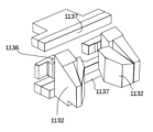
- the fitting claws 1132 are arranged in a pair on the left and right as shown in FIGS. 13 and 14, and are held by the advancing and retreating mechanism 1133 so as to be rotatable about a connecting portion 1136 .
- the engaging claws 1132 advance and retreat together with the advance and retreat mechanism 1133, and rotate about a connection portion 1136 with the advance and retreat mechanism 1133 at a position where the handle portion 29 of the tablet cassette 20 can be gripped, and operate to retract the handle portion 29.
- a space is provided that corresponds to the interval L1 described in Fig. 10 so that an adjacent engaging claw 1132 is positioned just in front of the adjacent tablet cassette 20 in front of it.
- the multiple engaging claws 1132 in the grip unit 113 each grip the tablet cassette 20 in front, so that the tablet cassette 20 can be held on the mounting table 1131 without requiring fine movement in the Z direction.
- the space required for the engaging claws 1132 to enter between the tablet cassettes 20 is the distance L1 described with reference to FIG.
- a plate-shaped member, the cassette holder 1137 is present in front of the advancing/retreating mechanism 1133. Therefore, when the engaging claw 1132 acts to clamp and surround the handle portion 29, which is the engaged portion, and pulls it in, the main body portion 22 of the tablet cassette 20 abuts against the cassette holder 1137, thereby fixing the position. In such a gripping state, a force that pulls in the engaging claws 1132 acts on the main body 22 via the handle portion 29, and a reaction force that pushes out acts from the cassette holder 1137, so that the posture is stable.
- Such a cassette holder 1137 may be provided in two places, for example, vertically around the handle portion 29, or may be provided only on one side, for example, only on the upper side.
- the advancing/retreating mechanism 1133 retracts the tablet cassette 20 together with the engaging claws 1132 in the advancing/retreating direction, and places the tablet cassette 20 on the placement table 1131 .
- the engaging claws 1132 and the advance/retract mechanism 1133 move together in the ⁇ X direction, which is the advance/retract direction perpendicular to the ZY direction, which is the movement direction of the transport arm unit 110, to function as a plurality of cassette holding sections that hold the tablet cassettes 20.
- the mounting table 1131 can hold up to six tablet cassettes 20 in the same manner, so by moving the catcher unit 112 with the tablet cassette 20 placed on the mounting table 1131, the catcher unit 112 can transport the tablet cassette 20 from the front unit 100 to the collector shelf 200 or the storage shelf 300.
- an identification member sensor 28 for reading the identification member 27 of the tablet cassette 20 is placed on the mounting table 1131, and can read the identification member 27 of the tablet cassette 20 transported to the storage shelf 300. Therefore, the control unit 550 stores the YZ coordinates, which are the position coordinates in the storage shelf 300 where the transport arm unit 110 is placed, in association with the identification information of the medicine stored in the identification member 27. In this way, by linking and storing the identification information of the medicine by the identification member 27 with the YZ coordinates, the control unit 550 can instruct the transport arm unit 110 of the necessary YZ coordinates when retrieving the necessary medicine according to the prescription data.
- the storage shelf 300 is a shelf having a shelf main body 302 and a base plate 301 .
- 12 flat base plates 301 that fit with the base portion 25 are arranged in one row and 10 vertical rows, but for simplicity, only a portion of them is shown in the figure.
- the tablet cassettes 20 placed on the storage shelf 300 are held in a state where they are fitted with the base plates 301, but this configuration is not limited to this.
- the base plate 301 is simply a plate-like member and does not need to have any mechanism that is particularly linked to the operation of the tablet cassettes 20.
- the collector shelf 200 is provided with a cassette base 30 for fitting the tablet cassette 20, and the tablet cassette 20 placed on the collector shelf 20 can eject the medicine stored inside the tablet cassette 20 one tablet at a time via the cassette base 30.
- the collector shelf 200 has a shelf body 202 on which the cassette bases 30 are arranged side by side, and a tablet drop path 201 which is a space formed between the shelf body 202 and an opening/closing plate 203 on the rear side of the shelf body 202.
- the collector shelf 200 is formed so that the tablet drop path 201 and the tablet discharge port 24 communicate with each other by fitting the tablet cassette 20 and the cassette base 30 together.
- the collector shelf 200 is configured such that eight cassette bases 30 are provided in each row in the horizontal direction and two shelves are provided in the vertical direction, but the number of shelves and the like can be changed as appropriate.
- a rocking device 50 is provided on the rear side of the collector shelf 200 in the -Z direction, within the movable range of the transport arm unit 110.
- the collector shelves 200 are arranged back to back in a left-right pair with the shelf main body 202 facing the movable range of the transport arm unit 110, so that two rocking devices 50 are also provided, one on each side of the medicine transport and dispensing device 500.
- the tablet cassette 20 is transported to the rocking device 50 by the transport arm unit 110.
- the specific configuration of the rocking device 50 will be described later.
- a tablet drop path 201 is formed between a shelf body 202 and an opening/closing plate 203, and a shutter mechanism 204 is provided at the lower end portion.
- the shutter mechanism 204 is normally kept in a closed state and functions as a shutter that blocks the falling path of the tablets discharged from the tablet cassette 20 so that they fall at the correct timing.
- the conveyor device 210 is known as a medicine transport section having a structure including a plurality of tablet containers 211 and a conveyor 212 composed of rollers and belts for moving the tablet containers 211 .
- the tablets that have fallen from the tablet drop path 201 through the hopper section 205 into the tablet container 211 are carried in the +Z direction by the conveyor device 210, and are finally transported from the hopper 70 arranged at the bottom of the front unit 100 to the packaging device 130.
- the collector shelf 200 is composed of the tablet drop path 201, the shutter mechanism 204, the hopper section 205, and the conveyor device 210, and is provided with a drug transport path connecting the collector shelf 200 and the packaging device 130.
- the tablets that have fallen into the hopper 70 are packaged in packaging paper 131 by a packaging device 130 as shown in FIG.
- the packaging device 130 is provided with: a wrapping strip feeding section 132 which holds a roll of the packet paper 131 and applies appropriate tension to send it out in sequence from the tip along the feed path of the packet paper 131; a printer 133 which prints on the packet paper 131; a vertical sealing section 134 which has a heating element extending in the width direction of the packet paper 131, i.e., in this embodiment, in the front and depth directions of Figure 18, and which heats and fuses the seal section 131a of the packet paper 131; two hoppers 70 on the left and right which move up and down to insert and remove the tip of the packet paper 131 which has been folded in half; a horizontal sealing section 135 which has a heating element extending horizontally and heats and fuses the packet paper 131; a roller section 136 which pulls the packet paper 131; and a cutter 137 which perforates and cuts the packet paper
- the packet paper 131 is filled with medications such as tablets and powdered medicine in sections of a specified length, and is discharged in a continuous manner to the downstream discharge outlet 139 with the seal portions 131a shown in shaded areas fused by heat.
- Packaging paper 131 is folded in half with its upper end open and is pulled out from packaging strip feeder 132.
- packaging strip feeder 132 is a packaging strip holder that feeds out packaging paper 131 wound up in a roll, for example, in a reel shape.
- the packet paper 131 sent out from the packaging belt supply section 132 is printed by the printer 133, moves to the bottom of the hopper 70, and is sealed at the front and rear in the conveying direction by the vertical sealing section 134. After that, the medicine is poured into the packet by the hopper 70, the top is sealed, and the packet is cut or perforated by the cutter 137 before being discharged.
- packaging paper 131 When hopper 70 detects that tablets have been placed into packaging paper 131, horizontal seal section 135 seals the top of packaging paper 131, and roller section 136 pulls in packaging paper 131 a predetermined amount, so that packaging paper 131 is transported the length of one packet. By repeating this operation, the packaging paper 131 is transported to the discharge port 139 as a series of medicine bags, each of which contains one packet of medicine.
- the packaging device 130 is a packaging device capable of packaging various medicines including tablets into individual packets in packaging paper 131 by using the configuration of each part as described above.
- the configuration of the packaging device 130 is described only as a type in which the packaging paper 131 is transported horizontally, but any other configuration is acceptable as long as the packaging machine is capable of dividing the packaging paper into sections of a specified width and sealing medicine in the divided chambers, and the configuration is not limited to this.
- the control unit 550 has a cassette control unit 551 , a transport control unit 552 , a swing control unit 553 , and a packaging control unit 554 .
- the cassette control unit 551 controls whether the tablet cassette 20 is correctly discharging tablets based on signals from various sensors provided on the cassette base 30 or the tablet cassette 20, such as the drop detection sensor 32 and the transmission drive unit 31. Furthermore, the cassette control unit 551 recognizes, based on signals from the identification member 27 and the identification member sensor 28, where in the medicine delivering and dispensing device 500 the tablet cassette 20 equipped with the corresponding identification member 27 is located.
- the transport control unit 552 is a part of a control means for controlling the transport arm unit 110 and the conveyor device 210 .
- the transport control unit 552 is a transport control means that moves the transport arm unit 110 to enable movement of the tablet cassette 20 based on the position coordinates of the tablet cassette 20 stored in the cassette control unit 551, and corrects these position coordinates based on signals from the cassette detection sensor 1135 and the shelf position detection sensor 1134, to transport the tablet cassette 20 to the correct position.
- the conveying control unit 552 controls the tablets to fall into a designated tablet container 211 by matching the timing of the movement of the conveyor device 210 with the timing at which the tablets discharged from the tablet cassette 20 pass through the hopper section 205 by opening the shutter mechanism 204.
- the packaging control unit 554 controls the operation of each part of the packaging device 130, including controlling the timing of pulling out the packaging paper 131.
- the rocking control section 553 is a rocking control means that controls each section of the rocking device 50, which will be described later.
- the transport control unit 552 grips the jammed tablet cassette 20 with the transport arm unit 110 and transports it to the swinging device 50 on the collector shelf 200 .
- a plurality of tablet cassettes 20 are arranged on the collector shelf 200 and the storage shelf 300 as already described.
- Each tablet cassette 20 stores one type of tablet therein.
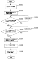
- the control unit 550 checks whether the required medicines and the number of medicines per package can be covered by the tablet cassettes 20 stored inside the medicine conveying and dispensing device 500 based on the prescription data (step S101). If there are medicines in short supply at this point, the operator may be prompted to place the tablet cassette 20 containing the required medicines on the storage and conveying unit 150, for example, by displaying a message indicating that the medicines are out of stock on the monitor 102.
- the operator may manually prepare the medicine using the manual preparation section 120 provided in the front unit 100, and the medicine may be divided into individual packets by the packaging device 130.
- the transport arm unit 110 moves to in front of the position of the tablet cassette 20 storing the necessary medicine, for example, tablets D, based on an instruction from the control unit 550 (step S102).
- the control unit 550 grasps the storage position of the tablet cassette 20 containing tablet D using the identification member 27, and moves the transport arm unit 110 based on the YZ coordinates (Yd, Zd) of the storage position of the tablet cassette 20 containing tablet D.
- the shelf position detection sensor 1134 detects the shelf position of the shelf main body 202, 302 of the collector shelf 200 or the storage shelf 300, and the YZ coordinates are fine-tuned based on the shelf position. Specifically, when the transport arm unit 110 moves to the YZ coordinate (Yd, Zd), the shelf position detection sensor 1134 checks whether the shelf main body 202 is located in the correct position when the correct YZ coordinate is reached (step S103).
- the shelf position detection sensor 1134 functions as a shelf position detection unit for detecting the positions of the shelves in the collector shelf 200 and the storage shelf 300 on which the tablet cassettes 20 are stored.
- the grip unit 113 moves up and down to estimate the location of the correct shelf position, and adjusts its position again based on the actual shelf positions of the shelf main body 202, 302 (step S104).
- the control unit 550 moves upward from the position coordinates (Yd, Zd) by the position coordinates (Yd + ⁇ y, Zd) and again determines whether the shelf position detection sensor 1134 detects the shelf main body 302.
- the control unit 550 corrects the Y coordinate of the tablet cassette 20 on the condition that the shelf position detection sensor 1134 has detected the position of the shelf main body 302 in this manner.
- control unit 550 uses the cassette detection sensor 1135 corresponding to the advancing/retreating mechanism 1133 to confirm whether the tablet cassette 20 is correctly positioned at the destination where the advancing/retreating mechanism 1133 has moved forward or backward (step S105). At this time, if the tablet cassette 20 is not in the desired position (i.e., in front of the advancing/retracting mechanism 1133 being extended), the cassette detection sensor 1135 moves again until it can detect the tablet cassette 20 in front (step S106).
- the control unit 550 corrects the Z coordinate of the tablet cassette 20 on the condition that the cassette detection sensor 1135 has thus detected the position of the tablet cassette 20 containing the tablet D.
- the control unit 550 When the advance/retract mechanism 1133 reaches the tablet cassette 20 containing the tablets D correctly in this way, the control unit 550 then extends the advance/retract mechanism 1133 to grip the handle portion 29 with the engaging claws 1132, and then retracts the advance/retract mechanism 1133 to place the tablet cassette 20 on the placement table 1131.
- the advancing/retreating mechanism 1133 when the advancing/retreating mechanism 1133 reaches the tablet cassette 20 placed on the storage shelf 300 , it grips the handle portion 29 with the engaging claws 1132 and operates to retract it, thereby gripping the tablet cassette 20 . With the tablet cassette 20 held, the advancing/retreating mechanism 1133 retreats, whereby the tablet cassette 20 moves onto the mounting table 1131 and its lower portion is supported by the mounting table 1131 (step S107).
- the cassette presser 1137 functions as a posture stabilizing member that stabilizes the posture of the tablet cassette 20 by applying a force in a direction that prevents the tablet cassette 20 from being drawn into the advancing and retracting mechanism 1133 .
- step S108 While being gripped by the grip unit 113, the tablet cassette 20 is carried to the collector shelf 200, and the grip unit 113 moves to a predetermined position on the collector shelf 200 where the tablet cassette 20 is to be placed (step S108). Note that the movement to the correct position on the collector shelf 200 at this time is the same as the operations in steps S103 to S106 already described, so a detailed explanation will be omitted.
- the grip unit 113 in contrast to when removing the tablet cassette 20 onto the loading platform 1131, confirms that there is no other tablet cassette 20 in front of the advancing/retreating mechanism 1133, then moves the advancing/retreating mechanism 1133 back and forth to release the engagement of the handle portion 29 with the engaging claw 1132, thereby engaging the tablet cassette 20 containing tablets D into the cassette base 30 of the collector shelf 200 (step S109).
- the transport arm unit 110 completes the movement of the tablet cassettes 20 required for the packaging operation based on the prescription data.
- the control unit 550 may determine the order of reciprocating movements so as to minimize the total moving distance of the transport arm unit 110. The operation from discharging the tablets D from the tablet cassette 20 after being placed on the collector shelf 200 until packaging has already been described, and therefore the description thereof will be omitted.
- the medicine delivering and dispensing device 500 has a transport arm unit 110 that can accurately manage and grip the position of the tablet cassette 20 without increasing costs.
- the transport arm unit 110 is capable of moving to the position coordinates of the collector shelf 200 and the storage shelf 300 storing the tablet cassette 20 to be transported, when the position coordinates are instructed by the control unit 550 .
- the transport arm unit 110 also has a shelf position detection sensor 1134 for detecting the position of the shelf main bodies 202, 302, which are the shelves on the collector shelf 200 and storage shelf 300 in which the tablet cassettes 20 are stored, and a cassette detection sensor 1135 for detecting that the tablet cassette 20 is in a position where it can be grasped.
- the control unit 550 corrects the position coordinates based on the position information of the shelf main body parts 202, 302 detected by the shelf position detection sensor 1134 and the cassette detection sensor 1135, and the position information of the tablet cassette 20, and moves to the front of the tablet cassette 20 to be transported.
- the control section 550 stores the YZ coordinates corresponding to the identification member 27 of the tablet cassette 20 . Therefore, when the control unit 550 determines based on the prescription data that the tablet cassette 20 storing the required tablets is not on the collector shelf 200 and that the tablet cassette 20 storing the same tablets is on the storage shelf 300, the transport arm unit 110 transports the tablet cassette 20 from the storage shelf 300 to the collector shelf 200.
- the transport arm unit 110 moves to the position coordinates instructed by the control unit 550, and then corrects the position coordinates based on the position information of the shelf main body parts 202, 302 detected by the shelf position detection sensor 1134 and the cassette detection sensor 1135, and the position information of the tablet cassette 20, thereby making it possible to accurately transport the desired tablet cassette.
- the drug transport and dispensing device 500 has a packaging device 130 for packaging the drugs dispensed from the collector shelf 200, and a drug transport path connecting the collector shelf 200 and the packaging device 130, with the packaging device 130, the collector shelf 200, and the storage shelf 300 being arranged in line in that order along the Z direction, which is the movable direction of the transport arm unit 110.
- a packaging device 130 for packaging the drugs dispensed from the collector shelf 200 and a drug transport path connecting the collector shelf 200 and the packaging device 130, with the packaging device 130, the collector shelf 200, and the storage shelf 300 being arranged in line in that order along the Z direction, which is the movable direction of the transport arm unit 110.
- the packaging device 130 on a straight line in the Z direction, which is the moving direction, at the outermost side in the +Z direction and outside the moving range, and by arranging the collector shelf 200 and the storage shelf 300 in the indicated order within the moving range of the transport arm unit 110, the distance between the collector shelf 200 and the packaging device 130 can be made relatively close, which also contributes to space-saving of the drug transport and dispensing device 500.
- the control section 550 stores the YZ coordinates corresponding to the identification member 27 of the tablet cassette 20 . Therefore, when the control unit 550 determines based on the prescription data that the tablet cassette 20 storing the required tablets is not on the collector shelf 200 and that the tablet cassette 20 storing the same tablets is on the storage shelf 300, the transport arm unit 110 transports the tablet cassette 20 from the storage shelf 300 to the collector shelf 200.
- the tablet cassette 20 is transported into and out of the device by an incoming transport section 150 and an outgoing transport section 160 .
- the control unit 550 uses the transport arm unit 110 to remove the tablet cassette 20 from the collector shelf 200 and transport it to the delivery storage unit 164.
- the operation of the tablet cassette 20 placed on the outgoing storage section 164 when it is transported by the outgoing transport section 160 and the detection by the sensors have already been described in the description of FIG. 5, and therefore will not be described here.
- the control unit 550 may display on the monitor 102 the reason why the tablet cassette 20 was released (for example, a shortage), and may also give the operator an instruction to replenish the tablet cassette, etc.
- an identification member sensor 28 may be disposed at the end position of the unloading transport section 160, making it possible to confirm information such as the type of tablets held in the unloaded tablet cassette 20.
- the conditions under which the tablet cassette 20 is transported to the delivery storage section 164 may include, in addition to refilling due to stockout as described above, when a jam cannot be cleared, or when a sufficient amount of time has passed since the last refill and the expiration date has passed.
- the monitor 102 when the tablet cassette 20 is discharged, the monitor 102 preferably displays information obtained by the identification member 27 of the discharged tablet cassette 20 as well as the reason why it was brought into the discharge transport section 160.
- the operator When the operator wishes to store new medicine in the medicine transporting and dispensing device 500, or when the operator wishes to return a refilled tablet cassette 20 back into the medicine transporting and dispensing device 500, the operator places the corresponding tablet cassette 20 in the storage and transport section 150 located at the back of the partition wall 101.
- the incoming detection sensor 157 detects the tablet cassette 20, and the incoming transport belt 151 rotates.
- the orientation and positional relationship of the tablet cassette 20 placed thereon are detected by a first direction detection sensor 155 and a second direction detection sensor 156 so that the tablet cassette 20 can be easily grasped by the transport arm unit 110.
- the incoming conveyor belt 151 is reversed to return the tablet cassette 20 to the upstream end position, and a message is displayed on the monitor 102 indicating that the tablet cassette 20 is placed in an incorrect orientation.
- the incoming conveyor belt 151 continues to rotate and continues to convey the tablet cassette 20 in the -Z direction.
- the receiving conveying belt 151 stops operating and the tablet cassette 20 waits for the operation of the conveying arm unit 110 in the receiving storage section 154.
- the specific operations of these direction detection units and the specific operation of the interval adjustment means 153 have been described with reference to FIGS. 6 to 8 and 10, respectively, and therefore will not be described here.
- the orientation of the tablet cassette 20 in the storage section 154 is uniquely determined.
- the engaging claw 1132 is engaged with the handle portion 29, making it easier to position the tablet cassette 20 when gripping it with the grip unit 113, which also contributes to increasing the speed of the device.
- a spacing adjustment means 153 is provided to maintain a spacing that allows a portion of the grip unit 113 to be inserted between the tablet cassettes 20.
- a gap adjustment means 153 it becomes easier for the grip unit 113 to grip the tablet cassette 20, and no other mechanism or the like is required to make it easier for the grip unit 113 to hold the tablet cassette 20.
- the inventory of the tablet cassettes 20 can be managed with a simple structure.
- the gap adjustment means 153 adjusts the gap between the tablet cassette 20 and another adjacent tablet cassette 20 by changing the rotation direction of the input conveyor belt 151.
- the gap adjustment means 153 also has a rotating L-shaped plate member 1531 arranged between the entrance conveyor belts 151, and a gap adjustment sensor 1532.
- the gap adjustment sensor 1532 detects the tablet cassette 20a
- the tip portion 1531a of the plate-like member 1531 moves in so as to separate the space between the tablet cassette 20a and the tablet cassette 20b, as shown in FIG. 22(b).
- the rotation direction of the incoming conveyor belt 151 is changed so as to move it in the reverse direction, i.e., in the +Z direction, as shown in Fig.
- the tip 1531a restricts the movement of the tablet cassette 20a, so that a gap La is generated between the tablet cassettes 20a and 20b. Since this gap La is equal to the amount of rotation of the reversed incoming conveyor belt 151, it is rotated in the reverse direction until it becomes twice the gap L1, and then the plate-like member 1531 is rotated to move it to a position where it does not interfere with the downward movement, and the incoming conveyor belt 151 is rotated forward to move it in the -Z direction as shown in Fig. 22(d).
- plate-shaped member 1531 is then inserted between tablet cassette 20b and tablet cassette 20c, and the rotation is reversed until distance Lb between tablet cassette 20b and tablet cassette 20c becomes distance L1.
- FIG. 22(e) only tablet cassette 20b is held down and tablet cassette 20a and tablet cassette 20c move in the +Z direction, so that the distances between the three tablet cassettes 20a, 20b, and 20c are adjusted to distance L1.
- the spacing adjustment means 153 adjusts the spacing between tablet cassettes 20 by changing the direction of rotation, such as forward and reverse rotation of the input conveying belt 151, the spacing between multiple tablet cassettes 20 can be adjusted to any value without increasing the number of spacing adjustment means 153.
- the movement of the tablet cassette 20 is restricted by the partition wall 101 even when the belt is reversed. Therefore, even if a tablet cassette 20 is input during the reverse rotation, it will not fall toward the operator.
- the discharge of tablets D from the tablet cassette 20 placed on the collector shelf 200 by the transport arm unit 110 will be described below.
- the discharge of tablets D from the tablet cassette 20 placed on the collector shelf 200 is controlled by a drop detection sensor 32 installed below the discharge port provided on the cassette base 30.
- the drop detection sensor 32 is an optical detection sensor, and when a tablet D is discharged from the tablet cassette 20, the drop detection sensor 32 detects the drop of the tablet D by utilizing the fact that the irradiated light is blocked.
- the control unit 550 determines that the tablet cassette 20 is jammed. In this way, the control unit 550 judges whether the tablet cassette 20 in the medicine delivering and dispensing device 500 is jammed or not. That is, the control unit 550 functions as a determination unit that determines whether the tablet cassette 20 is jammed based on whether the rotation shaft of the tablet cassette 20 placed on the cassette base 30 is rotating or not.
- the rotor 21 stops and tablets can no longer be ejected from the tablet cassette 20, which also causes the tablet dispensing operation from the drug transport and dispensing device 500 to stop. It is also conceivable that the clogged tablet cassette 20 may be replaced, or that the operator may retrieve and manually remove the tablet cassette 20 in order to clear the clog, but it is required to minimize the so-called downtime of such a drug delivery and dispensing device 500, and therefore a method for easily clearing such clogs is needed.
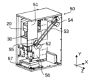
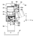
- a rocking device 50 is provided.
- the rocking device 50 has a cassette base 30 which is a cassette mounting portion to which the tablet cassette 20 can be attached, a rotating housing 51 which integrally holds the cassette base 30 and the tablet cassette 20, a rocking rotation shaft 52 connected to the rotating housing 51, a flat belt 53 wound around the rocking rotation shaft 52, and a rotation drive shaft 54 for rotating the flat belt 53 to rotate the rocking rotation shaft 52.
- Both the rotary drive shaft 54 and the oscillating rotary shaft 52 are supported by bearings fixed to the housing of the oscillating device 50, and further, the rotating housing 51 is attached to the oscillating rotary shaft 52.
- the rotating housing 51 can rotate within the XY plane with the oscillating rotary shaft 52 as the central axis, independently of the housing body of the oscillating device 50.
- the oscillating device 50 also has a jammed tablet discharge path 55 that is connected to the tablet discharge port 24 and is provided within the rotating housing 51, a trapezoidal receiving portion 56 that is fixed to the housing main body side of the oscillating device 50 and forms a tablet drop path together with the jammed tablet discharge path 55, and a discharge tray 57 that holds the discharged tablets.
- the rotating housing 51 is supported by a oscillating rotation shaft 52 so that it can rotate together with the cassette base 30 and the tablet cassette 20 placed on it, and the rotation of the rotation drive shaft 54 rotates the oscillating rotation shaft 52 via a flat belt 53 as shown in Figure 24, thereby rotating the rotating housing 51.
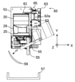
- the rocking device 50 also has an origin sensor 58 for verifying that the tablet cassette 20 and the rotating housing 51 are in the correct positions when the rotating housing 51 is in the upright position, which is the initial state, and a lid pressing mechanism 60 for pressing the lid portion 23 of the tablet cassette 20 placed on the cassette base 30 to prevent the lid portion 23 from being opened.
- the lid pressing mechanism 60 has a pressing member 61 which is a wide rod-shaped member with a tip that protrudes downward, a pressing drive unit 62 which moves the pressing member 61 up and down to bring the tip of the pressing member 61 into contact with the lid portion 23 of the tablet cassette 20, and a linear slider 63 which is a guide unit formed along the direction in which the pressing drive unit 62 moves the pressing member 61.
- the pressing drive portion 62 is attached in such a manner that the pressing member 61 is supported sideways at the tip of a protruding portion 62a that protrudes upward.
- the protrusion 62a is tapped for a screw, and moves up and down in the axial direction of the protrusion 62a by rotating the protrusion 62a with a rotary motor in the presser drive unit 62.
- the other end of the presser member 61 that does not contact the lid unit 23 engages with the linear slider 63, so that the presser member 61 also moves along the Y direction in which the linear slider 63 extends.
- the presser member 61 and the presser drive unit 62 function as a vertical drive unit that moves the presser member 61 up and down by the operation of the presser drive unit 62 to press down the upper part of the tablet cassette 20 .
- the pressing drive unit 62 is not limited to this configuration, and may be configured to move the pressing member 61 up and down by moving the protruding portion 62a like a piston.
- the origin detection dog 64 which is the detected part at the position of the pressing member 61, detects that it is at the origin position at the upper end because it is between the dog detection parts 65.
- the dog detection parts 65 are, for example, optical sensors that detect members placed between opposing flat plates. Furthermore, when the pressing drive portion 62 lowers the pressing member 61, the tip of the pressing member 61 comes into contact with the lid portion 23 at some position.
- lid pressing mechanism 60 When a driving member such as a motor is driven a predetermined amount so that lid portion 23 and pressing member 61 come into contact or are close to contacting each other, lid pressing mechanism 60 will not rise upward until the jam in tablet cassette 20 is cleared. At this time, since protruding portion 62a is threaded, lid portion 23 will not be opened even if a slight upward force is generated from the lid portion 23 side. In this manner, the tablet cassette 20 arranged on the cassette base 30 inside the rotating housing 51 maintains a pressed state in which the opening of the lid portion 23 is restricted by the lowering of the pressing member 61 .
- the cassette base 30 has a similar structure to that provided in the collector shelf 200.
- the rotor 21 can be rotated by fitting the transmission drive unit 31 into the base portion 25 of the tablet cassette 20. Therefore, the transmission drive unit 31 is an axial rotation unit that rotates the rotor 21, which is the rotation axis of the partition wall 26.
- the cassette base 30 of the rocking device 50 which is the cassette placement portion in the present invention, is fixed to a rotating housing 51, and rotates together with the tablet cassette 20 placed thereon when the rotating housing 51 rotates.
- the upper surface 33 of the cassette base 30 is a substantially horizontal plane parallel to the ground surface of the rocking device 50 or the ground surface of the medicine delivery/dispensing device 500 when the rotating housing 51 is in the upright position, which is the initial state of the rotating housing 51 .
- a jammed tablet discharge path 55 that rotates together with the rotating housing 51 is provided beyond the discharge outlet 24, and the tablets discharged by the rotation of the rotor 21 fall from the trapezoidal receiving portion 56 to the discharge tray 57 via the jammed tablet discharge path 55.
- the jammed tablet discharge path 55 is formed by an extension portion 55a extending from the discharge outlet 24 toward the -Y direction, a guide portion 55c formed on the +Z direction side so as to rise up relative to the rotational direction of the rotating housing 51, and a bent portion 55b formed between the extension portion 55a and the guide portion 55c.
- the jammed tablet discharge path 55 not linear but rather bent once along the way (in a so-called "L" shape)
- the momentum of the falling tablet is suppressed at the bent portion 55b, and the discharge direction is changed from the downward direction to the +Z direction.
- the jammed tablet discharge path 55 is simply provided linearly, the tablets will be discharged in the -Y direction.
- the tablets may roll vigorously in an oblique direction, and there is a concern that a receiving member 59 capable of covering rotation angles of 0° to 90° will be required so that the tablets are correctly guided to the discharge tray 57. If such a receiving member 59 is provided, it is undesirable that the coverage range of the receiving member 59 becomes large since it is arranged away from the rotating housing 51 so as not to interfere with the rotatable range of the rotating housing 51.
- the trapezoidal receiving portion 56 having an opening facing the -Z direction as shown by the black diagonal lines in Fig. 29 can cover the tablet discharged toward the front in the figure at a position relatively close to the guide portion 55c, it is preferable that the size of the trapezoidal receiving portion 56 itself does not need to be increased.
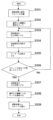
- the transport control unit 552 grips the jammed tablet cassette 20 with the transport arm unit 110 and transports it to the rocking device 50 on the collector shelf 200 (step S201).
- the pressing member 61 of the lid pressing mechanism 60 descends and comes into contact with the lid portion 23 at a position where it can press the lid portion 23 of the tablet cassette 20, and stops (step S202).
- the origin sensor 58 confirms that the tablet cassette 20 is in the initial state, that is, in the upright state (step S203).
- the rotation drive shaft 54 is rotated by an instruction from the swing control unit 553.
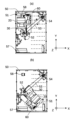
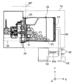
- the rotating housing 51 rotates the cassette base 30 and the tablet cassette 20 about the swing rotation shaft 52 in the XY plane from an upright state to a 135° inclined state as shown in Figures 20(a) and 20(b) (step S204).
- the swing control unit 553 counts the number of feeds of the stepping motor that rotates the rotation drive shaft 54, thereby controlling it to be 135°.
- step S204 the cassette base 30 and the tablet cassette 20 rotate together from the upright position to a 135 degree inclined position, so it is clear that the upper surface 33 of the cassette base 30, which was a horizontal plane parallel to the contact surface of the rocking device 50, is also now inclined at 135 degrees from the upper surface 33 when it was in the upright position.
- the oscillating rotation shaft 52, the rotation drive shaft 54, and the flat belt 53 function as a rotation drive mechanism for rotating the tablet cassette 20 and the cassette base 30 together until the top surface of the cassette base 30 is at an angle of 90 degrees or more
- the rotation drive shaft 54 mainly serves as the drive section for rotating the rotating housing 51.
- the inclination is set to 135 degrees, but it may be set to any angle greater than 90 degrees.
- the container side of the tablet cassette 20 is inclined at a 45 degree angle downward from the position of the rotor 21, so that the tablet D that has caused the "jam" is more likely to fall off to the main body portion 22 or lid portion 23 side.
- the lid portion 23 is held down by the lid holding mechanism 60 in step S103, the lid portion 23 is prevented from being accidentally opened by being pointed downward. In this manner, with the inclination angle set to 135 degrees, tablets can move more easily within the tablet cassette 20, making it possible to more reliably clear tablet jams.
- the upper surface 33 of the cassette base 30 in the upright position is shown imaginarily by a dashed line
- the upper surface 33 of the cassette base 30 in the inclined position is shown imaginarily by a dashed line.
- the swing control unit 553 rotates the rotary drive shaft 54 to tilt the tablet cassette 20, and rotates the transmission drive unit 31 to rotate the rotor 21. At this time, by rotating the tablet cassette 20 in the opposite direction to the rotation direction when it is normally discharged, it is possible to make it even easier to remove the jammed tablets D (step S205).
- step S206 After reversing the transmission drive unit 31 in step S205, the oscillation control unit 553 rotates it in the forward direction to determine whether the rotor 21 rotates without any problems (step S206).
- step S206 if the rotor 21 is still not rotating (i.e., the encoder does not detect the rotation of the transmission drive unit 31), i.e., if the jammed state exists, the rotary drive shaft 54 is rotated in the opposite direction, that is, counterclockwise, to return it to the upright state, and then the operations of steps S203 to S206 are repeated again.
- the operations may simply be repeated, or the operating speed may be increased, or forward/reverse rotation by the transmission drive unit 31 may be repeated, so that the control mode may be changed from the initial operations of steps S203 to S206.
- this shaking action is repeated until the "jam" of tablets D is eliminated.
- step S206 the swing control unit 553 functions as a discrimination unit that determines whether or not the jamming of the tablets D has been resolved based on the presence or absence of rotation when the transmission drive unit 31 rotates the rotor 21.
- step S206 if the rotor 21 rotates normally and the swing control unit 553 determines that the jamming of the tablets D has been cleared, the rotating casing 51 is returned to the upright position (step S207).
- the tablet D that was stuck due to the shaking action may be naturally discharged from the tablet discharge port 24.
- the tablet D discharged from the tablet discharge port 24 falls from the jammed tablet discharge path 55 through the trapezoidal receiving portion 56 onto the discharge tray 57 .
- the lid holding mechanism 60 unlocks the holding member 61 and raises the origin detection dog 64 until it is between the dog detection portions 65 (step S208).
- the control unit 550 instructs the transport arm unit 110 to move it from the oscillating device 50 to another position, such as the collector shelf 200 where the tablet cassette 20 was originally placed (step S209).
- the control unit 550 can automatically clear the clog in the tablet cassette 20, thereby shortening the time that the drug delivery and dispensing device 500 is stopped from dispensing.
- the drug transport and dispensing device 500 of the present invention comprises a transport arm unit 110 capable of grasping and transporting the tablet cassette 20 in which drugs are stored, a collector shelf 200 in which a plurality of tablet cassettes 20 can be stored by being attached to a cassette base 30 and which can dispense drugs from the stored tablet cassettes 20, a storage shelf 300 in which a plurality of tablet cassettes 20 can be stored, a packaging device 130 for packaging the drugs dispensed from the collector shelf 200, and a drug transport path connecting the collector shelf 200 and the packaging device 130. Further, the packaging device 130 , the collector shelf 200 , and the storage shelf 300 are arranged in this order along the movable direction of the transport arm unit 110 .
- the drug transport and dispensing device of the present invention has an incoming transport section 150 for supplying tablet cassettes 20 stored in the drug transport and dispensing device 500, and an outgoing transport section 160 for discharging emptied tablet cassettes from the drug transport and dispensing device 500, and both the incoming transport section 150 and the outgoing transport section 160 are arranged above the packaging device 130.
- the supply and discharge of the tablet cassettes 20 to the medicine delivering and dispensing device 500 is managed by the incoming transport unit 150 and the outgoing transport unit 160, thereby reducing the burden on the operator.
- the storage and transport section 150 has a first direction detection sensor 155 and a second direction detection sensor 156 for detecting that the orientation of the tablet cassette 20 is correct when the tablet cassette 20 is supplied.
- the incoming transport section 150 has an incoming transport belt 151 which transports the supplied tablet cassette 20 to a position where it can be grasped by the transport arm unit 110, and a spacing adjustment means 153 for adjusting the spacing between the tablet cassettes 20 arranged on the incoming transport belt 151 when transporting them to the above-mentioned position.
- tablet cassettes 20 being transported on the incoming conveying belt 151 are lined up in the incoming storage section 154 with an appropriate spacing between them by the spacing adjustment means 153, so that the transport arm unit 110 can efficiently transport them from the incoming storage section 154 to the storage shelf 300 or collector shelf 200.
- the gap adjustment means 153 has a gap adjustment sensor 1532 which is a gap adjustment detection unit that detects when the tablet cassette 20 has reached a predetermined position, and a plate-shaped member 1531 which is a regulating means that regulates the transport of the tablet cassette 20 in the input conveying section 150 by abutting against the base 25 of the tablet cassette 20, and when the tablet cassette 20 is transported by the input conveying belt 151, the plate-shaped member 1531 regulates the transport of the tablet cassette 20 until the gap between the tablet cassette 20 and another adjacent tablet cassette 20 becomes a predetermined value or more, thereby adjusting the gap between the tablet cassettes 20.
- a gap adjustment sensor 1532 which is a gap adjustment detection unit that detects when the tablet cassette 20 has reached a predetermined position
- a plate-shaped member 1531 which is a regulating means that regulates the transport of the tablet cassette 20 in the input conveying section 150 by abutting against the base 25 of the tablet cassette 20, and when the tablet cassette 20 is transported by the input conveying belt 151, the plate-
- tablet cassettes 20 being transported on the incoming conveying belt 151 are arranged in the incoming storage section 154 with an appropriate spacing between them by the spacing adjustment means 153, so that the transport arm unit 110 can efficiently transport them from the incoming storage section 154 to the storage shelf 300 or the collector shelf 200.
- the medicine delivering and dispensing device of the present invention has the following configuration.
- the gap adjusting means 153 adjusts the gap between one tablet cassette 20 and another adjacent tablet cassette 20 by changing the rotation direction of the input conveyor belt 151 .
- tablet cassettes 20 being transported on the incoming conveying belt 151 are arranged in the incoming storage section 154 with an appropriate spacing between them by the spacing adjustment means 153, so that the transport arm unit 110 can efficiently transport them from the incoming storage section 154 to the storage shelf 300 or the collector shelf 200.
- the medicine delivery and dispensing device of the present invention has the following configuration.
- the outgoing conveying section 160 has an outgoing conveying belt 161, and at the end of the outgoing conveying section 160, there is an end position detection sensor 166 which detects that the tablet cassette 20 arranged on the outgoing conveying belt 161 has reached the end position.
- the operation of the outgoing conveying belt 161 stops when the tablet cassette 20 reaches the end of the outgoing conveying belt 161, thereby reducing the risk of the tablet cassette 20 falling from the outgoing conveying section 160.
- the present invention provides an oscillating device 50 for clearing clogging of a tablet cassette 20 which comprises a main body 22 of a container capable of containing tablets, a rotor 21 which can rotate on its axis within the main body 22, and a rotating shaft for the rotor 21, and which successively discharges tablets from the main body 22 by causing the rotor 21 to rotate on its axis when the rotating shaft is rotated on its axis.
- the device has a cassette base 30 to which the tablet cassette 20 can be attached on its upper surface 33, and an oscillating rotating shaft 52, a rotating drive shaft 54, and a flat belt 53 which function as a rotation drive mechanism for rotating the tablet cassette 20 and the cassette base 30 together until the upper surface 33 of the cassette base 30 is at an angle of 90 degrees or more while maintaining the tablet cassette 20 attached to the cassette base 30.
- a so-called “jam” occurs in which tablets interfere with rotor 21 of tablet cassette 20 , the jam in tablet cassette 20 can be easily cleared by rocking device 50 .
- the rocking device of the present invention has a pressing member 61 that presses the upper part of the tablet cassette 20, and a pressing drive unit 62 that drives the pressing member 61 up and down, and the rotating drive shaft 54 rotates when the tip of the pressing member 61 abuts against the upper part of the tablet cassette 20.
- the cassette base 30 has a transmission drive unit 31 that is connected to the rotor 21 for rotating the rotor 21 about its axis, and after the rotating drive shaft 54 rotates the cassette base 30, the oscillating device 50 drives the rotor 21 by the transmission drive unit 31.
- the oscillating device 50 drives the rotor 21 by the transmission drive unit 31.
- the rocking device 50 in addition to the configuration described in any one of ⁇ 8> to ⁇ 10>, the rocking device 50 has a rocking control unit 553 which determines whether the tablet jam has been cleared depending on whether or not the transmission drive unit 31 rotates the rotor 21.
- the rocking control unit 553 determines that the jam has not been cleared
- the rotating drive shaft 54 returns the upper surface 33 of the cassette base 30 to an upright state, and then repeats the shaking operation of rotating the upper surface 33 of the cassette base 30 until it is at an angle of 90 degrees or more.
- the rocking control section 553 rotates the transmission drive section 31 forward and backward to determine whether the blockage has been cleared. According to this configuration, the swing control unit 553 can confirm that the rotor 21 is not clogged regardless of the rotation direction of the transmission drive unit 31, so that it is possible to more accurately determine whether the clog has been cleared.
- the rotary drive shaft 54 rotates the rotary housing 51 until the upper surface 33 of the cassette base 30 forms an angle of 135 degrees. According to this configuration, with the inclination angle set to 135 degrees, tablets are more likely to move within tablet cassette 20, so that tablet jamming can be more reliably cleared.
- the rocking device 50 of the present invention has a jammed tablet discharge path 55 connected to the cassette base 30 for recovering tablets discharged from the tablet cassette 20, a trapezoidal receiving portion 56, and a discharge tray 57 provided at the drop opening of the trapezoidal receiving portion 56.
- the medicine delivering and dispensing device 500 of the present invention includes a tablet cassette 20 which is provided with a main body 22 of a container capable of accommodating tablets, a rotor 21 which can rotate around its axis within the main body 22, and a rotation axis of the rotor 21, and which successively discharges tablets from the main body 22 as the rotor 21 rotates around its axis when the rotation axis is rotated, a transport arm unit 110 which can grasp and transport the tablet cassette 20, and a cassette base 30 which can store a plurality of tablet cassettes 20, and which rotates the rotation axis of the cassette base 30 to transport the stored tablet cassettes.
- the storage shelf 300 is capable of sequentially dispensing tablets from the collected tablet cassettes 20, a storage shelf 300 capable of storing a plurality of tablet cassettes 20, a packaging device 130 for packaging the tablets dispensed from the collector shelf 200, a tablet drop path 201, a shutter mechanism 204, a hopper section 205, and a conveyor device 210 which constitute a drug transport path connecting the collector shelf 200 to the packaging device 130, and a cassette control section 551 which determines whether the tablet cassette 20 is clogged based on whether or not the rotation axis of the tablet cassette 20 placed on the cassette base 30 is rotating.
- the transport arm unit 110 grasps and transports the tablet cassette 20 from the collector shelf 200 to the swinging device 50 .
- the transport arm unit 110 grasps and transports the tablet cassette 20 from the collector shelf 200 to the swinging device 50 .
- the transport arm unit 110 which is equipped with a transport arm unit 110 which automatically grasps and transports the tablet cassette 20 and uses the transport arm unit 110 to change the tablet cassette 20 placed on the cassette base 30 of the collector shelf 200, when a jam occurs in the tablet cassette 20, the jam can be automatically cleared without any user operation, thereby minimizing downtime of the drug transporting and dispensing device 500.
- the drug transport and dispensing device 500 of the present invention comprises a transport arm unit 110 capable of grasping and transporting a tablet cassette 20 in which drugs are contained, a collector shelf 200 in which a plurality of tablet cassettes 20 can be stored by being attached to a cassette base 30 and which can dispense drugs from the stored tablet cassettes 20, a storage shelf 300 in which a plurality of tablet cassettes 20 can be stored, a packaging device 130 for packaging the drugs dispensed from the collector shelf 200, and a drug transport path connecting the collector shelf 200 and the packaging device 130.
- the transport arm unit 110 can move to the position coordinates of the collector shelf 200 and storage shelf 300 in which the tablet cassette 20 to be transported is stored by being instructed by the control unit 550, and has a shelf position detection sensor 1134 for detecting the position of the shelf main body parts 202, 302 on the collector shelf 200 and storage shelf 300 in which the tablet cassette 20 is stored, and a cassette detection sensor 1135 for detecting that the tablet cassette 20 is in a position where it can be grasped.
- the medicine transport and dispensing device 500 corrects the position coordinates and moves to the front of the tablet cassette 20 to be transported based on the position information of the shelf main body parts 202, 302 detected by the shelf position detection sensor 1134 and the cassette detection sensor 1135, and the position information of the tablet cassette 20.
- the control unit 550 corrects the position coordinates of the tablet cassette 20 based on the detection results of the cassette detection sensor 1135 and the shelf position detection sensor 1134, so that the position of the tablet cassette 20 can be accurately determined.
- the transport arm unit 110 has a plurality of engaging claws 1132 and an advancing/retreating mechanism 1133 which move in the X direction perpendicular to the YZ direction which is the movement direction of the transport arm unit 110 to hold the tablet cassette 20, and has engaging claws 1132 which engage with the handle portion 29 of the tablet cassette 20 and operate to retract the handle portion 29 towards the advancing/retreating mechanism 1133, and a cassette holder 1137 which is located at least either above or below the engaging claws 1132 and which stabilizes the posture of the tablet cassette 20 by abutting against the tablet cassette 20 and applying a force in a direction which prevents the retraction by the engaging claws 1132.
- the cassette detection sensor 1135 is an optical detection sensor that is arranged in front of the engaging claw 1132 and the advancing/retracting mechanism 1133, and detects whether the tablet cassette 20 is positioned in the direction of travel of the irradiated light by irradiating light diagonally upward from the position of the cassette detection sensor 1135. With this configuration, operation is possible only after the cassette detection sensor 1135 detects the position of the tablet cassette 20, so that the tablet cassette 20 can be grasped with greater accuracy.
- the handle portion 29 of the tablet cassette 20 is translucent, and the lid portion 23 of the tablet cassette 20 is opaque to the extent that it blocks the irradiated light, and the cassette detection sensor 1135 detects the opaque lid portion 23 of the tablet cassette 20.
- the cassette detection sensor 1135 detects the opaque lid portion 23 of the tablet cassette 20.
- the medicine delivering and dispensing device of the present invention has the following configuration.
- the transport arm unit 110 moves to the position coordinates by an endless rail unit 111, and has an intermediate gear 114 that abuts on the side of the rail unit 111 opposite to the side that abuts on the catcher unit 112 to adjust the tension of the rail unit 111, and the intermediate gear 114 is fixed to the housing of the drug transport and dispensing device 500.
- the rail unit 111 is a timing belt having flexibility. With this configuration, there is less wear and tear compared to when metal or other materials are used, and since there is less tendency for the transport arm unit 110 to spin freely, there is less chance of a difference in the amount of movement of the transport arm unit 110 relative to the amount of rotation of the rail unit 111.
- Medicine delivery and dispensing device 1131 Placement table 1132... Engagement claw (claw portion) 1133...Advance/retract mechanism (part of the cassette holding portion) 1134: shelf position detection sensor (shelf position detection unit) 1135...Cassette detection sensor (cassette position detection unit) 1137...Cassette holder (attitude stabilizing member) 1531...Plate-shaped member (regulating means) 1532: Gap adjustment sensor (gap adjustment detection unit) Z direction...movement direction X direction...advance/retreat direction
Landscapes
- Health & Medical Sciences (AREA)
- Engineering & Computer Science (AREA)
- Pharmacology & Pharmacy (AREA)
- Medicinal Chemistry (AREA)
- Life Sciences & Earth Sciences (AREA)
- Animal Behavior & Ethology (AREA)
- General Health & Medical Sciences (AREA)
- Public Health (AREA)
- Veterinary Medicine (AREA)
- Chemical & Material Sciences (AREA)
- Quality & Reliability (AREA)
- Mechanical Engineering (AREA)
- Medical Preparation Storing Or Oral Administration Devices (AREA)
Abstract
La présente invention est caractérisée en ce qu'elle comprend une unité de transport (110) qui peut maintenir et transporter une cassette (20) dans laquelle un médicament est reçu, une première étagère de réception (200) qui peut stocker une pluralité de cassettes (20) sous une forme fixée à une base de cassette (30) et qui permet de distribuer un médicament à partir d'une cassette (20) stockée, une seconde étagère de réception (300) qui peut stocker une pluralité des cassettes (20), un dispositif d'emballage (130) pour emballer le médicament distribué à partir de la première étagère de réception (200), et un trajet de transport de médicament (210) qui relie la première étagère de réception (200) et le dispositif d'emballage (130), la présente invention étant en outre caractérisée en ce que le dispositif d'emballage (130), la première étagère de réception (200) et la seconde étagère de réception (300) sont agencés côte à côte dans l'ordre indiqué le long de la direction dans laquelle l'unité de transport (110) peut se déplacer.
Applications Claiming Priority (6)
| Application Number | Priority Date | Filing Date | Title |
|---|---|---|---|
| JP2023-105116 | 2023-06-27 | ||
| JP2023105116A JP2025005100A (ja) | 2023-06-27 | 2023-06-27 | 薬剤搬送払出装置 |
| JP2023109522A JP2025007852A (ja) | 2023-07-03 | 2023-07-03 | 揺動装置及び薬剤搬送払出装置 |
| JP2023-109522 | 2023-07-03 | ||
| JP2023-109762 | 2023-07-04 | ||
| JP2023109762A JP2025007979A (ja) | 2023-07-04 | 2023-07-04 | 薬剤搬送払出装置 |
Publications (1)
| Publication Number | Publication Date |
|---|---|
| WO2025005016A1 true WO2025005016A1 (fr) | 2025-01-02 |
Family
ID=93938564
Family Applications (1)
| Application Number | Title | Priority Date | Filing Date |
|---|---|---|---|
| PCT/JP2024/022658 Ceased WO2025005016A1 (fr) | 2023-06-27 | 2024-06-21 | Dispositif de transport et de distribution de médicaments |
Country Status (1)
| Country | Link |
|---|---|
| WO (1) | WO2025005016A1 (fr) |
Citations (5)
| Publication number | Priority date | Publication date | Assignee | Title |
|---|---|---|---|---|
| JP2005342122A (ja) * | 2004-06-01 | 2005-12-15 | Tosho Inc | 薬剤フィーダ及び自動調剤装置 |
| JP2009153635A (ja) * | 2007-12-26 | 2009-07-16 | Takazono Sangyo Co Ltd | 錠剤シートのポケット位置検出装置 |
| JP2019037340A (ja) * | 2017-08-23 | 2019-03-14 | 株式会社トーショー | 薬剤分包機 |
| WO2020158579A1 (fr) * | 2019-01-31 | 2020-08-06 | 株式会社湯山製作所 | Dispositif de manipulation de cassette et dispositif de manipulation de médicament |
| JP2022040353A (ja) * | 2017-01-19 | 2022-03-10 | 株式会社湯山製作所 | 散薬秤量装置及び薬剤分包システム |
-
2024
- 2024-06-21 WO PCT/JP2024/022658 patent/WO2025005016A1/fr not_active Ceased
Patent Citations (5)
| Publication number | Priority date | Publication date | Assignee | Title |
|---|---|---|---|---|
| JP2005342122A (ja) * | 2004-06-01 | 2005-12-15 | Tosho Inc | 薬剤フィーダ及び自動調剤装置 |
| JP2009153635A (ja) * | 2007-12-26 | 2009-07-16 | Takazono Sangyo Co Ltd | 錠剤シートのポケット位置検出装置 |
| JP2022040353A (ja) * | 2017-01-19 | 2022-03-10 | 株式会社湯山製作所 | 散薬秤量装置及び薬剤分包システム |
| JP2019037340A (ja) * | 2017-08-23 | 2019-03-14 | 株式会社トーショー | 薬剤分包機 |
| WO2020158579A1 (fr) * | 2019-01-31 | 2020-08-06 | 株式会社湯山製作所 | Dispositif de manipulation de cassette et dispositif de manipulation de médicament |
Similar Documents
| Publication | Publication Date | Title |
|---|---|---|
| CN102143734B (zh) | 药箱配发装置 | |
| US6625952B1 (en) | Medication collecting system | |
| US7040070B2 (en) | Tablet packing apparatus | |
| US6581355B1 (en) | Tablet filling device | |
| US6789996B2 (en) | Medicine feed apparatus | |
| CN101128359B (zh) | 药片填充装置 | |
| CN101795657A (zh) | 在药品包装机中自动分发各种形状的药片的分配器及其药片分配方法 | |
| CN101119893A (zh) | 药片填充装置 | |
| US20100147868A1 (en) | Apparatus for releasing drugs | |
| JP4964199B2 (ja) | 個別包装薬剤自動供給装置 | |
| WO2025053087A1 (fr) | Appareil de transport/distribution de médicaments et cassette de comprimés | |
| JP2025007852A (ja) | 揺動装置及び薬剤搬送払出装置 | |
| JP2025005100A (ja) | 薬剤搬送払出装置 | |
| JP2025007979A (ja) | 薬剤搬送払出装置 | |
| JP2025035689A (ja) | 薬剤搬送払出装置 | |
| JP2025031136A (ja) | 薬剤搬送払出装置 | |
| WO2025047484A1 (fr) | Dispositif de transport et de distribution de médicament | |
| JP2025031140A (ja) | 薬剤搬送払出装置 | |
| JP4386760B2 (ja) | 薬品払出装置 | |
| JP2013017503A (ja) | 薬品類カセット | |
| JP2005237713A (ja) | 薬品払出装置 |
Legal Events
| Date | Code | Title | Description |
|---|---|---|---|
| 121 | Ep: the epo has been informed by wipo that ep was designated in this application |
Ref document number: 24831877 Country of ref document: EP Kind code of ref document: A1 |
|
| NENP | Non-entry into the national phase |
Ref country code: DE |
|
| 122 | Ep: pct application non-entry in european phase |
Ref document number: 24831877 Country of ref document: EP Kind code of ref document: A1 |