WO2025009234A1 - Compresseur de suralimentation électrique - Google Patents
Compresseur de suralimentation électrique Download PDFInfo
- Publication number
- WO2025009234A1 WO2025009234A1 PCT/JP2024/012449 JP2024012449W WO2025009234A1 WO 2025009234 A1 WO2025009234 A1 WO 2025009234A1 JP 2024012449 W JP2024012449 W JP 2024012449W WO 2025009234 A1 WO2025009234 A1 WO 2025009234A1
- Authority
- WO
- WIPO (PCT)
- Prior art keywords
- end bell
- seal plate
- housing
- turbine
- electric supercharger
- Prior art date
- Legal status (The legal status is an assumption and is not a legal conclusion. Google has not performed a legal analysis and makes no representation as to the accuracy of the status listed.)
- Ceased
Links
Images
Classifications
-
- F—MECHANICAL ENGINEERING; LIGHTING; HEATING; WEAPONS; BLASTING
- F02—COMBUSTION ENGINES; HOT-GAS OR COMBUSTION-PRODUCT ENGINE PLANTS
- F02B—INTERNAL-COMBUSTION PISTON ENGINES; COMBUSTION ENGINES IN GENERAL
- F02B39/00—Component parts, details, or accessories relating to, driven charging or scavenging pumps, not provided for in groups F02B33/00 - F02B37/00
-
- F—MECHANICAL ENGINEERING; LIGHTING; HEATING; WEAPONS; BLASTING
- F02—COMBUSTION ENGINES; HOT-GAS OR COMBUSTION-PRODUCT ENGINE PLANTS
- F02B—INTERNAL-COMBUSTION PISTON ENGINES; COMBUSTION ENGINES IN GENERAL
- F02B39/00—Component parts, details, or accessories relating to, driven charging or scavenging pumps, not provided for in groups F02B33/00 - F02B37/00
- F02B39/02—Drives of pumps; Varying pump drive gear ratio
- F02B39/08—Non-mechanical drives, e.g. fluid drives having variable gear ratio
- F02B39/10—Non-mechanical drives, e.g. fluid drives having variable gear ratio electric
-
- H—ELECTRICITY
- H01—ELECTRIC ELEMENTS
- H01M—PROCESSES OR MEANS, e.g. BATTERIES, FOR THE DIRECT CONVERSION OF CHEMICAL ENERGY INTO ELECTRICAL ENERGY
- H01M8/00—Fuel cells; Manufacture thereof
- H01M8/04—Auxiliary arrangements, e.g. for control of pressure or for circulation of fluids
-
- H—ELECTRICITY
- H01—ELECTRIC ELEMENTS
- H01M—PROCESSES OR MEANS, e.g. BATTERIES, FOR THE DIRECT CONVERSION OF CHEMICAL ENERGY INTO ELECTRICAL ENERGY
- H01M8/00—Fuel cells; Manufacture thereof
- H01M8/04—Auxiliary arrangements, e.g. for control of pressure or for circulation of fluids
- H01M8/04082—Arrangements for control of reactant parameters, e.g. pressure or concentration
- H01M8/04089—Arrangements for control of reactant parameters, e.g. pressure or concentration of gaseous reactants
- H01M8/04111—Arrangements for control of reactant parameters, e.g. pressure or concentration of gaseous reactants using a compressor turbine assembly
Definitions
- This disclosure relates to an electric supercharger.
- an electric supercharger as described in Patent Document 1 below is known as a technology in this field.
- This electric supercharger includes a motor, and a turbine and a compressor arranged on either side of the motor in the axial direction.
- a rotating shaft connecting the turbine impeller and the compressor impeller passes through the motor, and a motor rotor is attached to the rotating shaft.
- a motor stator is arranged around the rotor in the motor case.
- the turbine housing or compressor housing is attached to the end bell of the motor.
- the housing may be attached to the end bell via a seal plate that seals between the inside of the motor and the inside of the housing. That is, for example, a seal plate may be fitted into the end bell, and the housing may be fitted into the seal plate to fix the housing in place.
- the present disclosure describes an electric turbocharger that can reduce the clearance between the housing and the impeller.
- the electric supercharger is an electric supercharger that includes a motor section having an end bell that holds a bearing of a rotating shaft, a housing that is fitted into the end bell and surrounds an impeller provided on the rotating shaft that protrudes from the bearing, and a seal plate that is fitted into the end bell to form a seal that seals between the inside of the motor section and the inside of the housing, and in which the fitting surface of the end bell with the housing and the fitting surface of the end bell with the seal plate are a common surface.
- the electric supercharger disclosed herein allows the clearance between the housing and the impeller to be reduced.
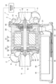
- FIG. 1 is a cross-sectional view showing an electric supercharger according to an embodiment.
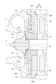
- FIG. 2 is an enlarged cross-sectional view showing a part of the electric supercharger shown in FIG. 1 .
- the gist of this disclosure is as follows: [1] to [4].
- An electric supercharger comprising a motor section having an end bell that holds a bearing for a rotating shaft, a housing that is fitted to the end bell and surrounds an impeller provided on the rotating shaft that protrudes from the bearing, and a seal plate that is fitted to the end bell to form a seal that seals between the inside of the motor section and the inside of the housing, and in which the fitting surface of the end bell with the housing and the fitting surface of the end bell with the seal plate are a common surface.
- the turbine 2 side of the electric supercharger 1 (left side in FIG. 1) may be simply referred to as the “turbine side,” and the compressor 3 side (right side in FIG. 1) may be simply referred to as the “compressor side.”
- FIG. 1 is a cross-sectional view showing an electric supercharger 1
- FIG. 2 is a cross-sectional view showing an enlarged portion of the electric supercharger.
- the electric supercharger 1 of this embodiment is an electrically assisted turbocharger mounted on a fuel cell vehicle.
- the electric supercharger 1 supplies the compressed air it generates to a fuel cell stack 91, increasing the amount of oxygen involved in the chemical reaction in the fuel cell stack 91.
- the electric supercharger 1 includes a turbine 2 and a compressor 3.
- the electric supercharger 1 further includes a motor unit 20 provided between the turbine 2 and the compressor 3, and an inverter unit 30 that supplies power to the motor unit 20.
- the turbine 2 includes a turbine housing 4 and a turbine impeller 6 housed in the turbine housing 4.
- the turbine housing 4 includes a scroll 12 extending circumferentially around the turbine impeller 6.
- the turbine housing 4 also includes an exhaust gas inlet 8 and an exhaust gas outlet 10.
- the compressor 3 includes a compressor housing 5 and a compressor impeller 7 housed in the compressor housing 5.
- the compressor housing 5 includes a scroll 13 extending circumferentially around the compressor impeller 7.
- the compressor housing 5 also includes an intake port 9 and a discharge port 11.
- the compressor 3 has a centrifugal compressor structure, and the compressor impeller 7 discharges air introduced axially from the intake port 9 radially outward toward the scroll 13.
- the electric supercharger 1 also includes a rotating shaft 15 that connects the turbine impeller 6 and the compressor impeller 7. That is, the turbine impeller 6 is provided on one end of the rotating shaft 15, and the compressor impeller 7 is provided on the other end of the rotating shaft 15.
- the turbine impeller 6, the rotating shaft 15, and the compressor impeller 7 integrally form a rotating body 19 that rotates around the rotation axis H.
- the motor section 20 includes a motor 21 and a motor case 23 that houses the motor 21.
- the motor 21 is, for example, a brushless AC motor, and includes a rotor 27, which is a rotor, and a stator 29, which is a stationary part.
- the rotor 27 is fixed to the rotating shaft 15, and is located between the turbine impeller 6 and the compressor impeller 7.
- the stator 29 is disposed so as to surround the periphery of the rotor 27, and is fixed to the motor case 23.
- the rotating shaft 15 also passes through the motor case 23 in the axial direction.
- the motor case 23 is provided with a pair of radial bearings 42, 43 that support the rotating shaft 15.
- the radial bearing 42 on the turbine side is located between the motor 21 and the turbine impeller 6.
- the radial bearing 43 on the compressor side is located between the motor 21 and the compressor impeller 7.
- the motor case 23 is also provided with a thrust bearing 45 for the rotating shaft 15.
- the thrust bearing 45 is located between the radial bearing 43 and the compressor impeller 7.
- the radial bearings 42, 43 and the thrust bearing 45 are air bearings.
- the inverter unit 30 is connected to the motor unit 20 via a connector 31.
- the inverter unit 30 includes an inverter case 33 arranged on the outside of the motor case 23, and an inverter body 35 and a bus bar 37 housed within the inverter case 33.
- the inverter body 35 is electrically connected to the stator 29 of the motor 21 via the bus bar 37 and the connector 31.
- exhaust gas discharged from the fuel cell stack 91 flows into the turbine housing 4 through the exhaust gas inlet 8.
- the exhaust gas then flows into the turbine impeller 6 through the scroll 12, causing the turbine impeller 6 to rotate around the rotation axis H.
- the exhaust gas then flows out of the turbine housing 4 through the exhaust gas outlet 10.
- the compressor impeller 7 rotates via the rotating shaft 15.
- the rotating compressor impeller 7 draws in outside air through the intake port 9. This air passes through the compressor impeller 7 and the scroll 13, is compressed, and is discharged from the discharge port 11.
- the compressed air discharged from the discharge port 11 is supplied to the fuel cell stack 91 described above.
- the motor 21 applies torque to the rotating shaft 15 to make up for the deficiency. That is, when a current is supplied from the inverter body 35 to the coil of the stator 29, a magnetic field is generated around the stator 29, and this magnetic field exerts a circumferential force on the permanent magnet of the rotor 27, resulting in the application of torque to the rotating shaft 15.
- Figure 2 is an enlarged cross-sectional view of the joint.
- the motor case 23 has a body section 51 that includes a cylindrical section that circumferentially surrounds the motor 21, and an end bell 53 that forms a lid on the turbine-side end face of the body section 51.
- the end bell 53 is roughly circular when viewed from the axial direction, and is fitted into the body section 51.
- the aforementioned radial bearing 42 is attached and held in a central hole in the end bell 53.
- a seal plate 55 is provided between the end bell 53 and the turbine housing 4.
- the seal plate 55 is generally circular when viewed in the axial direction, and a hole through which the rotating shaft 15 is inserted is provided in the center of the seal plate 55, with a labyrinth seal portion 57 provided in the hole.
- One end of the rotating shaft 15 protrudes from the radial bearing 42 in the center of the end bell 53 toward the turbine 2, and further protrudes from the labyrinth seal portion 57 of the seal plate 55, and the turbine impeller 6 is attached to the tip of this protruding rotating shaft 15.
- the labyrinth seal portion 57 forms a labyrinth structure in the gap between the outer circumferential surface of the boss portion 6a of the turbine impeller 6 and the seal plate 55, thereby sealing between the inside of the motor case 23 and the inside of the turbine housing 4.
- the labyrinth seal portion 57 has multiple ridges that protrude from the edge of the inner circumferential side of the seal plate 55 toward the inner circumferential side and extend in the circumferential direction.
- the turbine housing 4 is fitted into the end bell 53.
- the fit between the turbine housing 4 and the end bell 53 is a loose fit that allows the turbine housing 4 to be positioned radially relative to the end bell 53.
- the seal plate 55 is also fitted into the end bell 53.
- the fit between the seal plate 55 and the end bell 53 is also a loose fit that allows the seal plate 55 to be positioned radially relative to the end bell 53.
- the fit surface of the end bell 53 with the turbine housing 4 and the fit surface of the end bell 53 with the seal plate 55 are a common surface.
- the O-ring may be sandwiched between the turbine housing 4 and the seal plate 55 in the axial direction or may be sandwiched in the radial direction.
- the fitting structure of the turbine housing 4, the seal plate 55, and the end bell 53 will be described in more detail below.
- the end bell 53 has a mating surface 53a for mating the seal plate 55 with the turbine housing 4.
- the mating surface 53a extends in the entire circumferential direction at a position on the outer periphery side of the hole in which the radial bearing 42 is attached, and forms the inner circumferential surface of a cylinder with the rotation axis H as its cylindrical axis.
- a mating portion 4b is formed that protrudes in the axial direction toward the motor unit 20.
- the mating portion 4b is in the shape of a ring centered on the rotation axis H.
- the outer peripheral surface of the mating portion 4b extends over the entire circumferential direction and forms the outer peripheral surface of a cylinder with the rotation axis H as its cylindrical axis, forming a mating surface 4a that is mated with the end bell 53.
- the outer diameter of the cylindrical surface that forms the mating surface 4a is approximately the same as the outer diameter of the cylindrical surface that forms the mating surface 53a.
- the turbine housing 4 is mated with the end bell 53.
- the turbine housing 4 and the seal plate 55 are fitted to the end bells 53 that hold the radial bearings 42, and positioned radially. Therefore, compared to a structure in which the seal plate 55 is fitted to the end bells 53, and the turbine housing 4 is fitted to the seal plate 55, accumulation of the tolerances of the seal plate 55 and the turbine housing 4 is avoided, and the radial positional accuracy of the turbine housing 4 relative to the radial bearings 42 is improved.
- the seal plate 55 is fitted into the turbine housing 4
- accumulation of the tolerances of the turbine housing 4 and the seal plate 55 is avoided, improving the radial positional accuracy of the seal plate 55 relative to the radial bearing 42. Therefore, the clearance between the labyrinth seal portion 57 and the boss portion 6a of the turbine impeller 6 can be reduced. By reducing this clearance, the sealing performance of the labyrinth seal portion 57 is also improved.
- the electric supercharger 1 since the electric supercharger 1 is used to supply compressed air to the fuel stack of a fuel cell, there is a risk that compressed air contaminated with the above-mentioned lubricating oil and debris will be introduced into the fuel cell stack 91. If lubricating oil or debris gets into the fuel cell stack 91, it may cause problems such as a decrease in the power generation efficiency of the fuel cell stack 91. Therefore, there is a particular need to avoid the generation of lubricating oil and debris as described above, and a configuration that employs a labyrinth seal portion 57, which is a non-contact seal portion, is preferable.
Landscapes
- Engineering & Computer Science (AREA)
- Chemical & Material Sciences (AREA)
- Chemical Kinetics & Catalysis (AREA)
- Sustainable Development (AREA)
- Sustainable Energy (AREA)
- Manufacturing & Machinery (AREA)
- Life Sciences & Earth Sciences (AREA)
- Electrochemistry (AREA)
- General Chemical & Material Sciences (AREA)
- Combustion & Propulsion (AREA)
- Mechanical Engineering (AREA)
- General Engineering & Computer Science (AREA)
- Supercharger (AREA)
Abstract
Ce compresseur de suralimentation électrique comprend : une partie moteur ayant une cloche d'extrémité pour maintenir un palier radial d'un arbre rotatif ; un carter de turbine monté sur la cloche d'extrémité et entourant une roue de turbine disposée sur l'arbre rotatif faisant saillie à partir du palier radial ; et une plaque d'étanchéité montée sur la cloche d'extrémité pour former une partie de joint à labyrinthe afin d'assurer l'étanchéité entre l'intérieur de la partie moteur et l'intérieur du carter de turbine. Une surface d'ajustement de la cloche d'extrémité au carter de turbine et une surface d'ajustement de la cloche d'extrémité à la plaque d'étanchéité sont une surface commune.
Applications Claiming Priority (2)
| Application Number | Priority Date | Filing Date | Title |
|---|---|---|---|
| JP2023-110959 | 2023-07-05 | ||
| JP2023110959 | 2023-07-05 |
Publications (1)
| Publication Number | Publication Date |
|---|---|
| WO2025009234A1 true WO2025009234A1 (fr) | 2025-01-09 |
Family
ID=94171560
Family Applications (1)
| Application Number | Title | Priority Date | Filing Date |
|---|---|---|---|
| PCT/JP2024/012449 Ceased WO2025009234A1 (fr) | 2023-07-05 | 2024-03-27 | Compresseur de suralimentation électrique |
Country Status (1)
| Country | Link |
|---|---|
| WO (1) | WO2025009234A1 (fr) |
Citations (4)
| Publication number | Priority date | Publication date | Assignee | Title |
|---|---|---|---|---|
| WO2013084273A1 (fr) * | 2011-12-09 | 2013-06-13 | トヨタ自動車株式会社 | Moteur à combustion interne |
| US20170335756A1 (en) * | 2016-05-22 | 2017-11-23 | Honeywell International Inc. | Turbocharger with two-stage series compressor driven by exhaust gas-driven turbine and electric motor |
| WO2019159744A1 (fr) * | 2018-02-19 | 2019-08-22 | 株式会社Ihi | Turbine |
| US20200232387A1 (en) * | 2019-01-18 | 2020-07-23 | Ge Global Sourcing Llc | Systems for an electric turbocharger |
-
2024
- 2024-03-27 WO PCT/JP2024/012449 patent/WO2025009234A1/fr not_active Ceased
Patent Citations (4)
| Publication number | Priority date | Publication date | Assignee | Title |
|---|---|---|---|---|
| WO2013084273A1 (fr) * | 2011-12-09 | 2013-06-13 | トヨタ自動車株式会社 | Moteur à combustion interne |
| US20170335756A1 (en) * | 2016-05-22 | 2017-11-23 | Honeywell International Inc. | Turbocharger with two-stage series compressor driven by exhaust gas-driven turbine and electric motor |
| WO2019159744A1 (fr) * | 2018-02-19 | 2019-08-22 | 株式会社Ihi | Turbine |
| US20200232387A1 (en) * | 2019-01-18 | 2020-07-23 | Ge Global Sourcing Llc | Systems for an electric turbocharger |
Similar Documents
| Publication | Publication Date | Title |
|---|---|---|
| CN101688469B (zh) | 带电动机的增压机 | |
| CN108884757B (zh) | 增压器 | |
| US7837448B2 (en) | Supercharger | |
| US8096126B2 (en) | Motor-driven supercharger | |
| US7458214B2 (en) | Electric motor cartridge for an electrically assisted turbocharger | |
| CN101460724A (zh) | 电动增压器 | |
| CN101473515A (zh) | 马达转子以及其旋转平衡修正方法 | |
| CN113550799B (zh) | 具有带减小的轴向和径向累积的空气轴承的电动压缩机装置 | |
| US20090025386A1 (en) | Electrically assisted turbocharger | |
| CN120641667A (zh) | 离心压缩机 | |
| JP5322028B2 (ja) | モータロータ | |
| CN209586510U (zh) | 涡轮增压器和匹配环 | |
| JP7848517B2 (ja) | 遠心圧縮機 | |
| WO2025009234A1 (fr) | Compresseur de suralimentation électrique | |
| WO2020017161A1 (fr) | Compresseur électrique | |
| CN116635616A (zh) | 马达转子以及增压器 | |
| JP7494951B2 (ja) | 電動過給機 | |
| WO2020137649A1 (fr) | Pompe | |
| WO2025022708A1 (fr) | Compresseur de suralimentation électrique | |
| US20230204068A1 (en) | Turbo fluid machine | |
| CN217002047U (zh) | 涡轮机旁通阀和涡轮增压器 | |
| CN209539447U (zh) | 增压器 | |
| WO2025224939A1 (fr) | Dispositif de tuyau pour compresseur centrifuge électrique à étages multiples, et compresseur centrifuge électrique à étages multiples | |
| WO2025032816A1 (fr) | Corps rotatif, machine électrique rotative et compresseur électrique |
Legal Events
| Date | Code | Title | Description |
|---|---|---|---|
| 121 | Ep: the epo has been informed by wipo that ep was designated in this application |
Ref document number: 24835756 Country of ref document: EP Kind code of ref document: A1 |
|
| NENP | Non-entry into the national phase |
Ref country code: DE |