WO2025009326A1 - Dispositif d'embrayage - Google Patents
Dispositif d'embrayage Download PDFInfo
- Publication number
- WO2025009326A1 WO2025009326A1 PCT/JP2024/020745 JP2024020745W WO2025009326A1 WO 2025009326 A1 WO2025009326 A1 WO 2025009326A1 JP 2024020745 W JP2024020745 W JP 2024020745W WO 2025009326 A1 WO2025009326 A1 WO 2025009326A1
- Authority
- WO
- WIPO (PCT)
- Prior art keywords
- center
- side rotating
- clutch
- pressure
- plate
- Prior art date
- Legal status (The legal status is an assumption and is not a legal conclusion. Google has not performed a legal analysis and makes no representation as to the accuracy of the status listed.)
- Ceased
Links
Images






Classifications
-
- F—MECHANICAL ENGINEERING; LIGHTING; HEATING; WEAPONS; BLASTING
- F16—ENGINEERING ELEMENTS AND UNITS; GENERAL MEASURES FOR PRODUCING AND MAINTAINING EFFECTIVE FUNCTIONING OF MACHINES OR INSTALLATIONS; THERMAL INSULATION IN GENERAL
- F16D—COUPLINGS FOR TRANSMITTING ROTATION; CLUTCHES; BRAKES
- F16D13/00—Friction clutches
- F16D13/22—Friction clutches with axially-movable clutching members
- F16D13/38—Friction clutches with axially-movable clutching members with flat clutching surfaces, e.g. discs
- F16D13/52—Clutches with multiple lamellae ; Clutches in which three or more axially moveable members are fixed alternately to the shafts to be coupled and are pressed from one side towards an axially-located member
- F16D13/54—Clutches with multiple lamellae ; Clutches in which three or more axially moveable members are fixed alternately to the shafts to be coupled and are pressed from one side towards an axially-located member with means for increasing the effective force between the actuating sleeve or equivalent member and the pressure member
- F16D13/56—Clutches with multiple lamellae ; Clutches in which three or more axially moveable members are fixed alternately to the shafts to be coupled and are pressed from one side towards an axially-located member with means for increasing the effective force between the actuating sleeve or equivalent member and the pressure member in which the clutching pressure is produced by springs only
-
- F—MECHANICAL ENGINEERING; LIGHTING; HEATING; WEAPONS; BLASTING
- F16—ENGINEERING ELEMENTS AND UNITS; GENERAL MEASURES FOR PRODUCING AND MAINTAINING EFFECTIVE FUNCTIONING OF MACHINES OR INSTALLATIONS; THERMAL INSULATION IN GENERAL
- F16D—COUPLINGS FOR TRANSMITTING ROTATION; CLUTCHES; BRAKES
- F16D13/00—Friction clutches
- F16D13/58—Details
- F16D13/60—Clutching elements
- F16D13/64—Clutch-plates; Clutch-lamellae
- F16D13/69—Arrangements for spreading lamellae in the released state
-
- F—MECHANICAL ENGINEERING; LIGHTING; HEATING; WEAPONS; BLASTING
- F16—ENGINEERING ELEMENTS AND UNITS; GENERAL MEASURES FOR PRODUCING AND MAINTAINING EFFECTIVE FUNCTIONING OF MACHINES OR INSTALLATIONS; THERMAL INSULATION IN GENERAL
- F16D—COUPLINGS FOR TRANSMITTING ROTATION; CLUTCHES; BRAKES
- F16D43/00—Automatic clutches
- F16D43/02—Automatic clutches actuated entirely mechanically
- F16D43/20—Automatic clutches actuated entirely mechanically controlled by torque, e.g. overload-release clutches, slip-clutches with means by which torque varies the clutching pressure
- F16D43/202—Automatic clutches actuated entirely mechanically controlled by torque, e.g. overload-release clutches, slip-clutches with means by which torque varies the clutching pressure of the ratchet type
- F16D43/2022—Automatic clutches actuated entirely mechanically controlled by torque, e.g. overload-release clutches, slip-clutches with means by which torque varies the clutching pressure of the ratchet type with at least one part moving axially between engagement and disengagement
- F16D43/2024—Automatic clutches actuated entirely mechanically controlled by torque, e.g. overload-release clutches, slip-clutches with means by which torque varies the clutching pressure of the ratchet type with at least one part moving axially between engagement and disengagement the axially moving part being coaxial with the rotation, e.g. a gear with face teeth
-
- F—MECHANICAL ENGINEERING; LIGHTING; HEATING; WEAPONS; BLASTING
- F16—ENGINEERING ELEMENTS AND UNITS; GENERAL MEASURES FOR PRODUCING AND MAINTAINING EFFECTIVE FUNCTIONING OF MACHINES OR INSTALLATIONS; THERMAL INSULATION IN GENERAL
- F16D—COUPLINGS FOR TRANSMITTING ROTATION; CLUTCHES; BRAKES
- F16D13/00—Friction clutches
- F16D13/58—Details
- F16D13/70—Pressure members, e.g. pressure plates, for clutch-plates or lamellae; Guiding arrangements for pressure members
- F16D13/71—Pressure members, e.g. pressure plates, for clutch-plates or lamellae; Guiding arrangements for pressure members in which the clutching pressure is produced by springs only
-
- F—MECHANICAL ENGINEERING; LIGHTING; HEATING; WEAPONS; BLASTING
- F16—ENGINEERING ELEMENTS AND UNITS; GENERAL MEASURES FOR PRODUCING AND MAINTAINING EFFECTIVE FUNCTIONING OF MACHINES OR INSTALLATIONS; THERMAL INSULATION IN GENERAL
- F16D—COUPLINGS FOR TRANSMITTING ROTATION; CLUTCHES; BRAKES
- F16D13/00—Friction clutches
- F16D13/22—Friction clutches with axially-movable clutching members
- F16D13/38—Friction clutches with axially-movable clutching members with flat clutching surfaces, e.g. discs
- F16D13/52—Clutches with multiple lamellae ; Clutches in which three or more axially moveable members are fixed alternately to the shafts to be coupled and are pressed from one side towards an axially-located member
- F16D13/54—Clutches with multiple lamellae ; Clutches in which three or more axially moveable members are fixed alternately to the shafts to be coupled and are pressed from one side towards an axially-located member with means for increasing the effective force between the actuating sleeve or equivalent member and the pressure member
- F16D13/56—Clutches with multiple lamellae ; Clutches in which three or more axially moveable members are fixed alternately to the shafts to be coupled and are pressed from one side towards an axially-located member with means for increasing the effective force between the actuating sleeve or equivalent member and the pressure member in which the clutching pressure is produced by springs only
- F16D2013/565—Clutches with multiple lamellae ; Clutches in which three or more axially moveable members are fixed alternately to the shafts to be coupled and are pressed from one side towards an axially-located member with means for increasing the effective force between the actuating sleeve or equivalent member and the pressure member in which the clutching pressure is produced by springs only with means for releasing the clutch pressure in case of back torque
-
- F—MECHANICAL ENGINEERING; LIGHTING; HEATING; WEAPONS; BLASTING
- F16—ENGINEERING ELEMENTS AND UNITS; GENERAL MEASURES FOR PRODUCING AND MAINTAINING EFFECTIVE FUNCTIONING OF MACHINES OR INSTALLATIONS; THERMAL INSULATION IN GENERAL
- F16D—COUPLINGS FOR TRANSMITTING ROTATION; CLUTCHES; BRAKES
- F16D23/00—Details of mechanically-actuated clutches not specific for one distinct type
- F16D23/12—Mechanical clutch-actuating mechanisms arranged outside the clutch as such
- F16D2023/123—Clutch actuation by cams, ramps or ball-screw mechanisms
-
- F—MECHANICAL ENGINEERING; LIGHTING; HEATING; WEAPONS; BLASTING
- F16—ENGINEERING ELEMENTS AND UNITS; GENERAL MEASURES FOR PRODUCING AND MAINTAINING EFFECTIVE FUNCTIONING OF MACHINES OR INSTALLATIONS; THERMAL INSULATION IN GENERAL
- F16D—COUPLINGS FOR TRANSMITTING ROTATION; CLUTCHES; BRAKES
- F16D43/00—Automatic clutches
- F16D43/02—Automatic clutches actuated entirely mechanically
- F16D43/20—Automatic clutches actuated entirely mechanically controlled by torque, e.g. overload-release clutches, slip-clutches with means by which torque varies the clutching pressure
- F16D43/21—Automatic clutches actuated entirely mechanically controlled by torque, e.g. overload-release clutches, slip-clutches with means by which torque varies the clutching pressure with friction members
- F16D43/213—Automatic clutches actuated entirely mechanically controlled by torque, e.g. overload-release clutches, slip-clutches with means by which torque varies the clutching pressure with friction members with axially applied torque-limiting friction surfaces
- F16D43/215—Automatic clutches actuated entirely mechanically controlled by torque, e.g. overload-release clutches, slip-clutches with means by which torque varies the clutching pressure with friction members with axially applied torque-limiting friction surfaces with flat friction surfaces, e.g. discs
-
- F—MECHANICAL ENGINEERING; LIGHTING; HEATING; WEAPONS; BLASTING
- F16—ENGINEERING ELEMENTS AND UNITS; GENERAL MEASURES FOR PRODUCING AND MAINTAINING EFFECTIVE FUNCTIONING OF MACHINES OR INSTALLATIONS; THERMAL INSULATION IN GENERAL
- F16D—COUPLINGS FOR TRANSMITTING ROTATION; CLUTCHES; BRAKES
- F16D43/00—Automatic clutches
- F16D43/02—Automatic clutches actuated entirely mechanically
- F16D43/20—Automatic clutches actuated entirely mechanically controlled by torque, e.g. overload-release clutches, slip-clutches with means by which torque varies the clutching pressure
- F16D43/21—Automatic clutches actuated entirely mechanically controlled by torque, e.g. overload-release clutches, slip-clutches with means by which torque varies the clutching pressure with friction members
- F16D43/213—Automatic clutches actuated entirely mechanically controlled by torque, e.g. overload-release clutches, slip-clutches with means by which torque varies the clutching pressure with friction members with axially applied torque-limiting friction surfaces
- F16D43/215—Automatic clutches actuated entirely mechanically controlled by torque, e.g. overload-release clutches, slip-clutches with means by which torque varies the clutching pressure with friction members with axially applied torque-limiting friction surfaces with flat friction surfaces, e.g. discs
- F16D43/216—Automatic clutches actuated entirely mechanically controlled by torque, e.g. overload-release clutches, slip-clutches with means by which torque varies the clutching pressure with friction members with axially applied torque-limiting friction surfaces with flat friction surfaces, e.g. discs with multiple lamellae
Definitions
- the present invention relates to a clutch device.
- Patent Document 1 discloses a power transmission device (hereinafter referred to as a clutch device) that has an input member (hereinafter referred to as an input shaft) connected to the engine side, an output member (hereinafter referred to as an output shaft) connected to the driving wheel side, a clutch member (hereinafter referred to as a clutch center) connected to the output shaft, and a pressure member (hereinafter referred to as a pressure plate) that can be moved toward or away from the clutch center.
- a clutch device that has an input member (hereinafter referred to as an input shaft) connected to the engine side, an output member (hereinafter referred to as an output shaft) connected to the driving wheel side, a clutch member (hereinafter referred to as a clutch center) connected to the output shaft, and a pressure member (hereinafter referred to as a pressure plate) that can be moved toward or away from the clutch center.
- the clutch center and pressure plate in Patent Document 1 each have an assist cam surface that generates a force in a direction that moves the pressure plate closer to the clutch center when the rotational drive force of the engine can be transmitted to the output shaft, thereby increasing the pressing force (contact force) between the input side rotating plate and the output side rotating plate. Furthermore, the clutch device in Patent Document 1 has a disc spring that attenuates the pressing force in order to prevent a sudden increase in the assist torque due to the pressing force.
- Patent Document 1 the disc spring is held at the clutch center and is disposed at a position furthest from the pressure plate in the direction of movement of the pressure plate. For this reason, in a clutch device set with a relatively large pressing force or a clutch device with a relatively large number of output side rotating plates and input side rotating plates, a problem may arise in that the pressing force cannot be effectively attenuated.
- the present invention was made in consideration of these points, and its purpose is to provide a clutch device that can effectively dampen the pressing force generated by the action of the assist cam surface, thereby suppressing a sudden increase in assist torque.
- the clutch device of the present invention is a clutch device that transmits or interrupts the rotational driving force of an input shaft to an output shaft, and includes a clutch center that is accommodated in a clutch housing that holds a plurality of input side rotating plates that are rotationally driven by the rotational drive of the input shaft, holds a plurality of output side rotating plates arranged alternately with the input side rotating plates, and is rotationally driven together with the output shaft, a pressure plate that is arranged to be able to approach or move away from the clutch center and to rotate relatively thereto, and is able to press the input side rotating plates and the output side rotating plates, and a disc spring held by the clutch center, and the clutch center includes a center side cam portion having a center side assist cam surface that generates a force in a direction that brings the pressure plate closer to the clutch center in order to increase the pressing force between the input side rotating plates and the output side rotating plates when the clutch center rotates relative to the pressure plate, and the pressure plate is arranged to be able to rotate relative to the clutch center.
- the clutch center has a pressure-side cam portion having a pressure-side assist cam surface that generates a force in a direction that moves the pressure plate closer to the clutch center in order to increase the pressing force between the input side rotating plate and the output side rotating plate when the pressure plate rotates relative to the center.
- the disc spring is provided so as to be able to come into contact with the output side rotating plate held by the clutch center, is disposed between the output side rotating plates held by the clutch center that are adjacent in the moving direction, and is located in the second direction from the center of the moving direction from the first output side rotating plate that is furthest in the first direction to the second output side rotating plate that is furthest in the second direction among the multiple output side rotating plates held by the clutch center.
- the disc spring held by the clutch center is provided so as to be able to come into contact with the output side rotating plate held by the clutch center, is disposed between the output side rotating plates adjacent in the moving direction held by the clutch center, and is positioned in the second direction from the center of the moving direction from the first output side rotating plate to the second output side rotating plate.
- the disc spring is disposed in a position closer to the pressure plate that generates the pressing force, so that the pressing force can be effectively attenuated. This makes it possible to suppress a sudden increase in the assist torque, and suppresses the occurrence of sudden clutch engagement and vibration.
- Another clutch device is a clutch device for transmitting or interrupting the rotational driving force of an input shaft to an output shaft, comprising: a clutch center housed in a clutch housing that holds a plurality of input side rotating plates that are rotationally driven by the rotational driving of the input shaft and that rotates together with the output shaft; a pressure plate that is arranged to be able to approach or move away from the clutch center and to rotate relatively thereto, holds at least a portion of a plurality of output side rotating plates that are arranged alternately with the input side rotating plates, and is capable of pressing the input side rotating plates and the output side rotating plates; and a disc spring held by the pressure plate, and when the clutch center rotates relative to the pressure plate, the input side rotating plates and the output side rotating plates are pressed against each other by the pressure plate.
- the pressure plate has a center-side cam portion having a center-side assist cam surface that generates a force in a direction that moves the pressure plate closer to the clutch center in order to increase the pressing force between the input side rotating plate and the output side rotating plate when the pressure plate rotates relative to the clutch center
- the pressure plate has a pressure-side cam portion having a pressure-side assist cam surface that generates a force in a direction that moves the pressure plate closer to the clutch center in order to increase the pressing force between the input side rotating plate and the output side rotating plate when the pressure plate rotates relative to the clutch center
- the disc spring is aligned with the output side rotating plate held by the pressure plate in the moving direction and is arranged to be able to come into contact with the output side rotating plate held by the pressure plate.
- the disc spring held by the pressure plate is aligned in the direction of movement with the output side rotating plate held by the pressure plate, and is arranged so as to be able to come into contact with the output side rotating plate held by the pressure plate.
- the disc spring since the disc spring is arranged on the pressure plate which generates a pressing force, the pressing force can be effectively attenuated. This makes it possible to suppress a sudden increase in the assist torque, and suppresses the occurrence of sudden clutch engagement and vibration.
- the present invention provides a clutch device that can effectively dampen the pressing force generated by the action of the assist cam surface, thereby suppressing a sudden increase in assist torque.
- FIG. 1 is a cross-sectional view of a clutch device according to one embodiment.
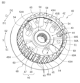
- FIG. 2 is a perspective view of a clutch center according to one embodiment.
- FIG. 3 is a plan view of the clutch center according to one embodiment.
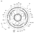
- FIG. 4 is a perspective view of a pressure plate according to one embodiment.
- FIG. 5 is a plan view of a pressure plate according to one embodiment.
- FIG. 6 is a perspective view of a pressure plate according to one embodiment.
- FIG. 7 is a plan view of a pressure plate according to one embodiment.
- FIG. 8A is a schematic diagram for explaining the action of the center side assist cam surface and the pressure side assist cam surface.
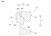
- FIG. 8B is a schematic diagram for explaining the action of the center-side slipper cam surface and the pressure-side slipper cam surface.
- FIG. 9 is a cross-sectional view of a clutch device according to another embodiment.
- First Embodiment 1 is a cross-sectional view of a clutch device 10 according to this embodiment.
- the clutch device 10 is provided on a saddle-type vehicle such as a motorcycle.
- the clutch device 10 is a device that transmits or cuts off the rotational driving force of an input shaft (crankshaft) of an engine, which is a power source of the motorcycle, to an output shaft 15.
- the clutch device 10 is a device that transmits or cuts off the rotational driving force of the input shaft to a driving wheel (rear wheel) via the output shaft 15.
- the clutch device 10 is disposed between the engine and the transmission.
- direction D the direction in which the pressure plate 70 of the clutch device 10 approaches and moves away from the clutch center 40 (i.e. the direction in which the pressure plate 70 moves) is referred to as direction D
- first direction D1 the direction in which the pressure plate 70 approaches the clutch center 40
- second direction D2 the direction in which the pressure plate 70 moves away from the clutch center 40
- Direction D is an example of a moving direction.
- the circumferential direction (i.e., the rotation direction) of the clutch center 40 and the pressure plate 70 is defined as the circumferential direction S
- the direction from one center side cam portion 60 to the other center side cam portion 60 (the direction from one pressure side cam portion 90 to the other pressure side cam portion 90) in relation to the circumferential direction S is defined as the first circumferential direction S1 (see FIG. 2)
- the direction from the other center side cam portion 60 to one center side cam portion 60 (the direction from the other pressure side cam portion 90 to one pressure side cam portion 90) is defined as the second circumferential direction S2 (see FIG. 2).
- the axial direction of the output shaft 15 is the same as the direction D.
- the pressure plate 70 and the clutch center 40 rotate in the first circumferential direction S1 (i.e., the direction from the center side assist cam surface 60A of one center side cam portion 60 to the center side slipper cam surface 60S).
- first circumferential direction S1 i.e., the direction from the center side assist cam surface 60A of one center side cam portion 60 to the center side slipper cam surface 60S.
- the clutch device 10 includes an output shaft 15, a plurality of input side rotating plates 20, a plurality of output side rotating plates 22, a clutch housing 30, a clutch center 40, a pressure plate 70, a stopper plate 100, and a disc spring 120.
- the output shaft 15 is a hollow shaft body.
- One end of the output shaft 15 rotatably supports the input gear 35 and clutch housing 30 (described later) via a needle bearing 15A.
- the output shaft 15 fixedly supports the clutch center 40 via a nut 15B.
- the output shaft 15 rotates integrally with the clutch center 40.
- the other end of the output shaft 15 is connected to, for example, a transmission (not shown) of a motorcycle.
- the output shaft 15 is provided with a push rod 16A in its hollow portion 15H and a push member 16B provided adjacent to the push rod 16A.
- the hollow portion 15H functions as a flow passage for clutch oil.
- the clutch oil flows inside the output shaft 15, i.e., inside the hollow portion 15H.
- the push rod 16A and the push member 16B are provided so as to be able to slide inside the hollow portion 15H of the output shaft 15.
- One end (the end on the left side in the figure) of the push rod 16A is connected to a clutch operating mechanism (e.g., a clutch operating lever) of the motorcycle (not shown), and slides inside the hollow portion 15H by operating the clutch operating mechanism to press the push member 16B in the second direction D2.
- a clutch operating mechanism e.g., a clutch operating lever
- a part of the push member 16B protrudes outward from the output shaft 15 (here, in the second direction D2) and is connected to a release bearing 18 provided on the pressure plate 70.
- the push rod 16A and the push member 16B are formed to be smaller than the inner diameter of the hollow portion 15H, ensuring the flow of clutch oil within the hollow portion 15H.
- the clutch housing 30 is made of an aluminum alloy.
- the clutch housing 30 is formed in a cylindrical shape with a bottom. As shown in FIG. 1, the clutch housing 30 has a bottom wall 31 formed in a substantially circular shape, and a side wall 33 extending from an edge of the bottom wall 31 in a second direction D2.
- the clutch housing 30 holds a plurality of input side rotating plates 20.
- the clutch housing 30 holds the input side rotating plates 20 so that they can move relatively in the direction D and cannot move relatively in the circumferential direction S.
- an input gear 35 is provided on the bottom wall 31 of the clutch housing 30.
- the input gear 35 is fixed to the bottom wall 31 by rivets 35B via a torque damper 35A.
- the input gear 35 meshes with a drive gear (not shown) that rotates due to the rotational drive of the input shaft of the engine.
- the input gear 35 rotates integrally with the clutch housing 30, independent of the output shaft 15.
- the input side rotating plate 20 is rotated by the rotational drive of the input shaft. As shown in FIG. 1, the input side rotating plate 20 is held on the inner peripheral surface of the side wall 33 of the clutch housing 30. The input side rotating plate 20 is held in the clutch housing 30 by spline fitting. The input side rotating plate 20 is provided so that it can be displaced along the axial direction of the clutch housing 30 (i.e., direction D). The input side rotating plate 20 is provided so that it can rotate integrally with the clutch housing 30.
- the input side rotating plate 20 is a member that is pressed against the output side rotating plate 22.
- the input side rotating plate 20 is formed in an annular shape.
- the input side rotating plate 20 is molded by aluminum die casting. Friction material (not shown) made of multiple pieces of paper is attached to the front and back surfaces of the input side rotating plate 20. Grooves several hundred ⁇ m deep are formed between the friction materials to hold clutch oil.
- the clutch center 40 is accommodated in the clutch housing 30.
- the clutch center 40 is arranged concentrically with the clutch housing 30.
- the clutch center 40 is made of an aluminum alloy.
- the clutch center 40 has a cylindrical body 42 and a flange 68 extending radially outward from the outer periphery of the body 42.
- the clutch center 40 holds the input side rotating plate 20 and a plurality of output side rotating plates 22 arranged alternately in direction D.
- the clutch center 40 holds the output side rotating plates 22 so that they can move relatively in direction D and cannot move relatively in the circumferential direction S.
- the clutch center 40 holds the input side rotating plate 20 so that they can move relatively in direction D and cannot move relatively in the circumferential direction S.
- the clutch center 40 rotates together with the output shaft 15.
- the main body 42 includes an annular base wall 43, an outer peripheral wall 45 located radially outward of the base wall 43 and extending in the second direction D2, an output shaft holding portion 50 provided in the center of the base wall 43, a plurality of center side cam portions 60 connected to the base wall 43 and the outer peripheral wall 45, and a center side fitting portion 58.
- the output shaft holding portion 50 is formed in a cylindrical shape.
- An insertion hole 51 is formed in the output shaft holding portion 50, into which the output shaft 15 is inserted and spline-fitted.
- the insertion hole 51 is formed penetrating the base wall 43.
- the inner circumferential surface 50A of the output shaft holding portion 50 that forms the insertion hole 51 has a plurality of spline grooves formed along the axial direction.
- the output shaft 15 is connected to the output shaft holding portion 50.
- the outer peripheral wall 45 of the clutch center 40 is disposed radially outward from the output shaft holding portion 50.
- a spline fitting portion 46 is provided on the outer peripheral surface 45A of the outer peripheral wall 45.
- the spline fitting portion 46 has a plurality of center side fitting teeth 47 extending in the axial direction of the clutch center 40 along the outer peripheral surface 45A of the outer peripheral wall 45, a plurality of spline grooves 48 formed between adjacent center side fitting teeth 47 and extending in the axial direction of the clutch center 40, and an oil discharge hole 49.
- the center side fitting teeth 47 hold the output side rotating plate 22.
- the center side fitting teeth 47 hold the output side rotating plate 22 so that it can move relatively in the direction D and cannot move relatively in the circumferential direction S.
- the center side fitting teeth 47 are arranged in the circumferential direction S.
- the center side fitting teeth 47 are formed at equal intervals in the circumferential direction S.
- the center side fitting teeth 47 are formed in the same shape.
- the center side fitting teeth 47 protrude radially outward from the outer peripheral surface 45A of the outer peripheral wall 45.
- the oil discharge holes 49 are formed by penetrating the outer peripheral wall 45 in the radial direction.
- the oil discharge holes 49 are formed between the adjacent center side fitting teeth 47. That is, the oil discharge holes 49 are formed in the spline grooves 48.
- the oil discharge holes 49 are formed on the side of the center side cam portion 60.
- the oil discharge holes 49 are formed on the side of the center side slipper cam surface 60S of the center side cam portion 60.
- the oil discharge holes 49 are formed on the first circumferential direction S1 side of the center side slipper cam surface 60S.
- the oil discharge holes 49 are formed on the second circumferential direction S2 side of the boss portion 54 described later.
- the oil discharge holes 49 are formed in threes at three locations in the circumferential direction S of the outer peripheral wall 45.
- the oil drain holes 49 are arranged at equal intervals in the circumferential direction S.
- the oil drain holes 49 connect the inside and outside of the clutch center 40.
- the oil drain holes 49 are holes that drain the clutch oil that has flowed into the clutch center 40 from the output shaft 15 to the outside of the clutch center 40.
- the oil drain holes 49 drain the clutch oil that flows on the inner circumferential surface 45B side of the outer circumferential wall 45 to the outside of the clutch center 40. At least a portion of the oil drain holes 49 is provided in a position that faces the pressure side fitting portion 88 described later.
- the output side rotating plate 22 is held by the splined engagement portion 46 of the clutch center 40 and the pressure plate 70.
- a part of the output side rotating plate 22 is held by the clutch center 40. More specifically, a part of the output side rotating plate 22 is held by the center side engagement teeth 47 and the spline grooves 48 of the clutch center 40 through spline engagement.
- Another part of the output side rotating plate 22 is held by the pressure plate 70. More specifically, the other part of the output side rotating plate 22 is held by the pressure side engagement teeth 77 (see FIG. 4) of the pressure plate 70, which will be described later.
- the output side rotating plate 22 is provided so as to be displaceable along the axial direction of the clutch center 40 (i.e., direction D).
- the output side rotating plate 22 is provided so as to be rotatable integrally with the clutch center 40.
- the output side rotating plate 22 is a member that is pressed against the input side rotating plate 20.
- the output side rotating plate 22 is a flat plate formed into an annular shape.
- the output side rotating plate 22 is formed by punching a thin plate material made of SPCC material into an annular shape.
- the friction material provided on the input side rotating plate 20 may be provided on the output side rotating plate 22 instead of the input side rotating plate 20, or may be provided on both the input side rotating plate 20 and the output side rotating plate 22.
- the center side cam portion 60 is formed in a platform shape having a cam surface made of an inclined surface that constitutes an Assist & Slipper (registered trademark) mechanism that generates an assist torque, which is a force that increases the pressing force (pressure contact force) between the input side rotating plate 20 and the output side rotating plate 22, or a slipper torque, which is a force that causes the input side rotating plate 20 and the output side rotating plate 22 to separate early and transition to a half-clutch state.
- the center side cam portion 60 is formed so as to protrude from the base wall 43 in the second direction D2. As shown in FIG. 3, the center side cam portions 60 are disposed at equal intervals in the circumferential direction S of the clutch center 40.
- the clutch center 40 has three center side cam portions 60, but the number of center side cam portions 60 is not limited to three.
- the center side cam portion 60 is located radially outside the output shaft holding portion 50.
- the center side cam portion 60 has a center side assist cam surface 60A and a center side slipper cam surface 60S.
- the center side assist cam surface 60A is configured to generate a force in a direction that moves the pressure plate 70 closer to the clutch center 40 in order to increase the pressing force (pressure contact force) between the input side rotating plate 20 and the output side rotating plate 22 when rotating relative to the pressure plate 70.
- the position of the pressure plate 70 relative to the clutch center 40 does not change, and the pressure plate 70 does not need to physically approach the clutch center 40. It is noted that the pressure plate 70 may be physically displaced relative to the clutch center 40.
- the center-side slipper cam surface 60S is configured to move the pressure plate 70 away from the clutch center 40 in order to reduce the pressing force (pressure contact force) between the input-side rotating plate 20 and the output-side rotating plate 22 when rotating relative to the pressure plate 70.
- the center-side assist cam surface 60A of one center-side cam portion 60L and the center-side slipper cam surface 60S of the other center-side cam portion 60M are arranged opposite each other in the circumferential direction S.
- the clutch center 40 has a plurality of bosses 54 (three in this embodiment).
- the bosses 54 are members that indirectly support the pressure plate 70.
- the bosses 54 hold the pressure plate 70 via a stopper plate 100 (see FIG. 1) and a pressure spring 25 (see FIG. 1), which will be described later.
- the plurality of bosses 54 are arranged at equal intervals in the circumferential direction S.
- the bosses 54 are formed in a cylindrical shape.
- the bosses 54 are located radially outward from the output shaft holding portion 50.
- the bosses 54 extend toward the pressure plate 70 (i.e., toward the second direction D2).
- the bosses 54 are provided on the base wall 43.
- the bosses 54 have a screw hole 54H formed therein, into which the bolt 28 (see FIG. 1) is inserted.
- the screw hole 54H extends in the axial direction of the clutch center 40.
- the clutch center 40 has a center-side cam hole 43H that penetrates a portion of the base wall 43.
- the center-side cam hole 43H penetrates the base wall 43 in direction D.
- the center-side cam hole 43H extends from the side of the output shaft holding portion 50 to the outer peripheral wall 45.
- the center-side cam hole 43H is formed between the center-side assist cam surface 60A of the center-side cam portion 60 and the boss portion 54. When viewed from the axial direction of the clutch center 40, the center-side assist cam surface 60A and a portion of the center-side cam hole 43H overlap.
- the center side fitting portion 58 is located radially outward from the output shaft holding portion 50.
- the center side fitting portion 58 is located radially outward from the center side cam portion 60.
- the center side fitting portion 58 is located in the second direction D2 from the center side cam portion 60.
- the center side fitting portion 58 is formed on the inner peripheral surface 45B of the outer peripheral wall 45.
- the center side fitting portion 58 is configured to be slidably fitted onto the pressure side fitting portion 88 (see FIG. 4) described later.
- the inner diameter of the center side fitting portion 58 is formed with a fitting tolerance that allows the flow of clutch oil flowing out from the tip portion 15T (see FIG. 1) of the output shaft 15 relative to the pressure side fitting portion 88. That is, a gap is formed between the center side fitting portion 58 and the pressure side fitting portion 88 described later.
- the pressure plate 70 is arranged so as to be able to approach or move away from the clutch center 40 and to rotate relative to it.
- the pressure plate 70 is configured so as to be able to press the input side rotating plate 20 and the output side rotating plate 22.
- the pressure plate 70 is arranged concentrically with the clutch center 40 and the clutch housing 30.
- the pressure plate 70 is formed from an aluminum alloy.
- the pressure plate 70 has a main body 72 and a flange 98 that is connected to the outer peripheral edge of the main body 72 in the second direction D2 and extends radially outward.
- the main body 72 protrudes in the first direction D1 beyond the flange 98.
- the pressure plate 70 holds a plurality of output side rotating plates 22 arranged alternately with the input side rotating plates 20.
- the pressure plate 70 holds the output side rotating plates 22 so as to be able to move relatively in the direction D and to be unable to move relatively in the circumferential direction S.
- the pressure plate 70 holds the input side rotating plate 20 so that it can move relatively in the direction D and relatively in the circumferential direction S.
- the main body 72 includes a cylindrical portion 80, a plurality of pressure side cam portions 90, a pressure side fitting portion 88, and a spring housing portion 84 (see also FIG. 6).
- the flange 98 extends radially outward from the outer peripheral edge of the main body 72.
- the flange 98 extends radially outward from the outer peripheral edge of the pressure side fitting portion 88.
- the flange 98 has a pressing surface 98A that applies a pressing force to the input side rotating plate 20 and the output side rotating plate 22.
- the pressing surface 98A is a surface that directly or indirectly contacts the input side rotating plate 20 and the output side rotating plate 22.
- the pressing surface 98A sandwiches the input side rotating plate 20 and the output side rotating plate 22 between itself and the flange 68 of the clutch center 40.
- the cylindrical portion 80 is formed in a cylindrical shape.
- the cylindrical portion 80 is formed integrally with the pressure side cam portion 90.
- the cylindrical portion 80 accommodates the tip portion 15T (see FIG. 1) of the output shaft 15.
- the cylindrical portion 80 accommodates the release bearing 18 (see FIG. 1).
- the cylindrical portion 80 is a portion that receives the pressing force from the push member 16B.
- the cylindrical portion 80 is a portion that receives the clutch oil that flows out from the tip portion 15T of the output shaft 15.
- the pressure side cam portion 90 is formed in a platform shape having a cam surface made of an inclined surface that constitutes an Assist & Slipper (registered trademark) mechanism that slides against the center side cam portion 60 to generate an assist torque or slipper torque.
- the pressure side cam portion 90 is formed so as to protrude in the first direction D1 beyond the flange 98.
- the pressure side cam portions 90 are disposed at equal intervals in the circumferential direction S of the pressure plate 70.
- the pressure plate 70 has three pressure side cam portions 90, but the number of pressure side cam portions 90 is not limited to three.
- the pressure side cam portion 90 is located radially outside the cylindrical portion 80.
- the pressure side cam portion 90 has a pressure side assist cam surface 90A (see also FIG. 7) and a pressure side slipper cam surface 90S.
- the pressure side assist cam surface 90A is configured to be able to come into contact with the center side assist cam surface 60A.
- the pressure side assist cam surface 90A is configured to generate a force in a direction that brings the pressure plate 70 closer to the clutch center 40 in order to increase the pressing force (pressure contact force) between the input side rotating plate 20 and the output side rotating plate 22 when rotating relative to the clutch center 40.
- the pressure side slipper cam surface 90S is configured to be able to come into contact with the center side slipper cam surface 60S.
- the pressure side slipper cam surface 90S is configured to move the pressure plate 70 away from the clutch center 40 in order to reduce the pressing force (pressure contact force) between the input side rotating plate 20 and the output side rotating plate 22 when rotating relative to the clutch center 40.
- the pressure side assist cam surface 90A of one pressure side cam portion 90L and the pressure side slipper cam surface 90S of the other pressure side cam portion 90M are arranged opposite each other in the circumferential direction S.
- the pressure plate 70 has a pressure side cam hole 73H that penetrates a part of the main body 72 and the flange 98.
- the pressure side cam hole 73H is located radially outward from the cylindrical portion 80.
- the pressure side cam hole 73H extends from the side of the cylindrical portion 80 to a radially outward position from the pressure side fitting portion 88.
- the pressure side cam hole 73H is formed to penetrate between adjacent pressure side cam portions 90.
- the pressure side cam hole 73H is formed to penetrate between the pressure side assist cam surface 90A and the pressure side slipper cam surface 90S of adjacent pressure side cam portions 90.
- the pressure side assist cam surface 90A and a part of the pressure side cam hole 73H overlap.
- the spring accommodating portion 84 is formed in the pressure side cam portion 90.
- the spring accommodating portion 84 is formed so as to be recessed from the second direction D2 to the first direction D1.
- the spring accommodating portion 84 is formed in an elliptical shape.
- the spring accommodating portion 84 accommodates the pressure spring 25 (see Figure 1).
- An insertion hole 84H into which the boss portion 54 (see Figure 2) is inserted is formed through the spring accommodating portion 84. That is, the insertion hole 84H is formed through the pressure side cam portion 90.
- the insertion hole 84H is formed in an elliptical shape.
- the pressure spring 25 is housed in the spring housing portion 84.
- the pressure spring 25 is held by the boss portion 54 inserted into the insertion hole 84H of the spring housing portion 84.
- the pressure spring 25 biases the pressure plate 70 toward the clutch center 40 (i.e., toward the first direction D1).
- the pressure spring 25 is, for example, a coil spring made of spring steel wound in a spiral shape.
- the pressure side fitting portion 88 is provided on the main body 72.
- the pressure side fitting portion 88 is located radially outward from the pressure side cam portion 90.
- the pressure side fitting portion 88 is located in the second direction D2 from the pressure side cam portion 90.
- the pressure side fitting portion 88 is configured to be slidably fitted into the center side fitting portion 58 (see FIG. 2).
- the pressure plate 70 has a plurality of pressure side mating teeth 77 formed on the flange 98.
- the pressure side mating teeth 77 hold the output side rotating plate 22.
- the pressure side mating teeth 77 hold the output side rotating plate 22 so that it is relatively movable in direction D and relatively immovable in the circumferential direction S.
- the pressure side mating teeth 77 hold the input side rotating plate 20.
- the pressure side mating teeth 77 hold the input side rotating plate 20 so that it is relatively movable in direction D and relatively movable in the circumferential direction S.
- the pressure side mating teeth 77 are located radially outward from the cylindrical portion 80.
- the pressure side mating teeth 77 are located radially outward from the pressure side cam portion 90.
- the pressure side mating teeth 77 are located radially outward from the pressure side mating portion 88.
- the multiple pressure side mating teeth 77 are aligned in the circumferential direction S.
- the pressure side mating teeth 77 are arranged at equal intervals in the circumferential direction S. In this embodiment, some of the pressure side mating teeth 77 have been removed, so the intervals in those areas are wider, but the remaining adjacent pressure side mating teeth 77 are arranged at equal intervals.
- the stopper plate 100 is provided so as to be able to come into contact with the pressure plate 70.
- the stopper plate 100 is a member that prevents the pressure plate 70 from moving away from the clutch center 40 by more than a predetermined distance in the second direction D2.
- the stopper plate 100 is fixed to the boss portion 54 of the clutch center 40 by the bolt 28.
- the pressure plate 70 is fixed by tightening the bolt 28 to the boss portion 54 via the stopper plate 100 with the boss portion 54 of the clutch center 40 and the pressure spring 25 arranged in the spring accommodating portion 84.
- the stopper plate 100 is formed in a substantially triangular shape in a plan view.
- the disc spring 120 is held by the clutch center 40.
- the disc spring 120 is held by the center side mating teeth 47 in contact with the outer peripheral surface of the center side mating teeth 47.
- the disc spring 120 is held by the center side mating teeth 47 so as to be movable relative to the center side mating teeth 47 in the direction D and in the circumferential direction S.
- the disc spring 120 is formed, for example, from carbon steel.
- the disc spring 120 is aligned in the direction D with the output side rotating plate 22 held by the clutch center 40.
- the disc spring 120 is arranged so as to be able to come into contact with the output side rotating plate 22 held by the clutch center 40.
- the disc spring 120 attenuates the pressing force in the direction from the pressure plate 70 toward the clutch center 40 (i.e., the first direction D1).
- the disc spring 120 is arranged between the output side rotating plates 22 adjacent to each other in the direction D held by the clutch center 40.
- the disc spring 120 is located in the second direction D2 from the center CL in the direction D from the first output side rotating plate 22A located furthest in the first direction D1 to the second output side rotating plate 22B located furthest in the second direction D2 among the multiple output side rotating plates 22 held by the clutch center 40.
- the disc spring 120 is located between the third output side rotating plate 22C located in the first direction D1 further from the second output side rotating plate 22B among the multiple output side rotating plates 22 held by the clutch center 40 and adjacent to the second output side rotating plate 22B, and the second output side rotating plate 22B.
- the disc spring 120 is in contact with the second output side rotating plate 22B and the third output side rotating plate 22C.
- the input side rotating plate 20 is arranged radially outside the disc spring 120.
- the outer diameter of the disc spring 120 is smaller than the outer diameter of the output side rotating plate 22.
- the disc springs 120 are arranged between the output side rotating plates 22, it is not necessary to arrange an iron sheet material between the disc springs 120 and the output side rotating plates 22.
- the disc spring 120 held by the clutch center 40 is provided so as to be able to come into contact with the output side rotating plate 22 held by the clutch center 40, and is disposed between the output side rotating plates 22 adjacent in the direction D held by the clutch center 40, and is positioned in the second direction D2 from the center CL of the direction D from the first output side rotating plate 22A to the second output side rotating plate 22B.
- the disc spring 120 is disposed in a position closer to the pressure plate 70 that generates the pressing force, and therefore the pressing force can be effectively attenuated. This makes it possible to suppress a sudden increase in the assist torque, and to suppress the sudden engagement of the clutch and the occurrence of vibration.
- the disc spring 120 is located between the second output side rotating plate 22B and the third output side rotating plate 22C, which is located in the first direction D1 further than the second output side rotating plate 22B among the multiple output side rotating plates 22 held by the clutch center 40 and adjacent to the second output side rotating plate 22B. According to the above aspect, the disc spring 120 is located closer to the pressure plate 70 that generates the pressing force, so that the pressing force can be attenuated more effectively.
- the disc spring 120 and the output side rotating plate 22 are held by the center side mating teeth 47. According to the above aspect, the disc spring 120 and the output side rotating plate 22 are prevented from falling off the clutch center 40.
- Second Embodiment 9 is a cross-sectional view of a clutch device 210 according to the second embodiment.
- the clutch device 210 has a similar configuration to the clutch device 10, except that the disc spring 120 is disposed in a different position.
- the disc spring 120 is held by the pressure plate 70.
- the disc spring 120 abuts against the outer peripheral surface of the pressure side mating teeth 77 and is held by the pressure side mating teeth 77.
- the disc spring 120 is held by the pressure side mating teeth 77 so as to be movable relative to the pressure side mating teeth 77 in direction D and circumferential direction S.
- the disc spring 120 is aligned in direction D with the output side rotating plate 22 held by the pressure plate 70.
- the disc spring 120 is arranged so as to be able to come into contact with the output side rotating plate 22 held by the pressure plate 70.
- the disc spring 120 is disposed between the outermost output side rotating plate 22E, which is located furthest in the second direction D2 among the output side rotating plates 22 held by the pressure plate 70, and the flange 98. More specifically, the disc spring 120 is disposed between the outermost output side rotating plate 22E and the pressing surface 98A of the flange 98. An iron sheet material 122 is disposed between the disc spring 120 and the flange 98. This prevents the disc spring 120 from coming into direct contact with the flange 98, thereby suppressing wear of the flange 98.
- the input side rotating plate 20 is disposed radially outward of the disc spring 120.
- the disc spring 120 held by the pressure plate 70 is aligned with the output side rotating plate 22 held by the pressure plate 70 in direction D, and is arranged so as to be able to come into contact with the output side rotating plate 22 held by the pressure plate 70.
- the disc spring 120 since the disc spring 120 is arranged on the pressure plate 70 which generates a pressing force, the pressing force can be effectively attenuated. This makes it possible to suppress a sudden increase in the assist torque, and to suppress the occurrence of sudden clutch engagement and vibration.
- the disc spring 120 is located between the flange 98 and the outermost output side rotating plate 22E, which is located furthest in the second direction D2 among the output side rotating plates 22 held by the pressure plate 70. According to the above aspect, the disc spring 120 is located furthest in the second direction D2, so that the pressing force can be attenuated more effectively.
- the disc spring 120 and the output side rotating plate 22 are held by the pressure side mating teeth 77. According to the above aspect, the disc spring 120 and the output side rotating plate 22 are prevented from falling off the pressure plate 70.
- the clutch center 40 holds a portion of the output side rotating plate 22, and the pressure plate 70 holds another portion of the output side rotating plate 22.
- the force can be increased by increasing the number of output side rotating plates 22 that are held by the pressure plate 70.
- the clutch center 40 holds a portion of the output side rotating plate 22, and the pressure plate 70 holds another portion of the output side rotating plate 22, but this is not limited to this.
- the clutch center 40 may be configured to hold all of the output side rotating plates 22, or the pressure plate 70 may be configured to hold all of the output side rotating plates 22.
- the disc spring 120 is disposed between the flange 98 and the output side rotating plate 22, but this is not limited to this.
- the disc spring 120 may be disposed between adjacent output side rotating plates 22 held by the pressure plate 70.
- the invention of claim 4 includes cases where the pressure plate holds some of the output side rotating plates, and cases where the pressure plate holds all of the output side rotating plates.
Landscapes
- Engineering & Computer Science (AREA)
- General Engineering & Computer Science (AREA)
- Mechanical Engineering (AREA)
- Mechanical Operated Clutches (AREA)
- One-Way And Automatic Clutches, And Combinations Of Different Clutches (AREA)
Abstract
Priority Applications (3)
| Application Number | Priority Date | Filing Date | Title |
|---|---|---|---|
| EP24835844.2A EP4650617A1 (fr) | 2023-07-04 | 2024-06-06 | Dispositif d'embrayage |
| CN202480020298.4A CN120898085A (zh) | 2023-07-04 | 2024-06-06 | 离合器装置 |
| US19/302,347 US20250369487A1 (en) | 2023-07-04 | 2025-08-18 | Clutch device |
Applications Claiming Priority (2)
| Application Number | Priority Date | Filing Date | Title |
|---|---|---|---|
| JP2023110206A JP7789723B2 (ja) | 2023-07-04 | 2023-07-04 | クラッチ装置 |
| JP2023-110206 | 2023-07-04 |
Related Child Applications (1)
| Application Number | Title | Priority Date | Filing Date |
|---|---|---|---|
| US19/302,347 Continuation US20250369487A1 (en) | 2023-07-04 | 2025-08-18 | Clutch device |
Publications (1)
| Publication Number | Publication Date |
|---|---|
| WO2025009326A1 true WO2025009326A1 (fr) | 2025-01-09 |
Family
ID=94171875
Family Applications (1)
| Application Number | Title | Priority Date | Filing Date |
|---|---|---|---|
| PCT/JP2024/020745 Ceased WO2025009326A1 (fr) | 2023-07-04 | 2024-06-06 | Dispositif d'embrayage |
Country Status (5)
| Country | Link |
|---|---|
| US (1) | US20250369487A1 (fr) |
| EP (1) | EP4650617A1 (fr) |
| JP (1) | JP7789723B2 (fr) |
| CN (1) | CN120898085A (fr) |
| WO (1) | WO2025009326A1 (fr) |
Citations (3)
| Publication number | Priority date | Publication date | Assignee | Title |
|---|---|---|---|---|
| JP2005114121A (ja) * | 2003-10-10 | 2005-04-28 | Dainatsukusu:Kk | 湿式多板摩擦係合装置 |
| JP2012057728A (ja) * | 2010-09-09 | 2012-03-22 | Honda Motor Co Ltd | 遠心クラッチ付き車両 |
| WO2020116507A1 (fr) * | 2018-12-05 | 2020-06-11 | 株式会社エフ・シー・シー | Dispositif de transmission de puissance |
Family Cites Families (8)
| Publication number | Priority date | Publication date | Assignee | Title |
|---|---|---|---|---|
| JP4797008B2 (ja) * | 2007-09-26 | 2011-10-19 | 本田技研工業株式会社 | 多板クラッチ |
| JP5191819B2 (ja) * | 2008-06-27 | 2013-05-08 | 本田技研工業株式会社 | 多板クラッチ |
| JP5995439B2 (ja) | 2011-12-28 | 2016-09-21 | 株式会社エフ・シー・シー | 動力伝達装置 |
| JP6295690B2 (ja) * | 2014-02-04 | 2018-03-20 | スズキ株式会社 | バックトルクリミッターを有するクラッチ |
| JP6501354B2 (ja) * | 2015-05-12 | 2019-04-17 | 株式会社エフ・シー・シー | 車両用動力伝達システム |
| JP6603143B2 (ja) * | 2016-01-25 | 2019-11-06 | 株式会社エフ・シー・シー | 動力伝達装置 |
| IT202000005533A1 (it) * | 2020-03-16 | 2021-09-16 | Piaggio & C Spa | Frizione |
| JP2025184720A (ja) * | 2024-06-06 | 2025-12-18 | 正昭 平井 | 高汎用性合板断熱素材 |
-
2023
- 2023-07-04 JP JP2023110206A patent/JP7789723B2/ja active Active
-
2024
- 2024-06-06 CN CN202480020298.4A patent/CN120898085A/zh active Pending
- 2024-06-06 EP EP24835844.2A patent/EP4650617A1/fr active Pending
- 2024-06-06 WO PCT/JP2024/020745 patent/WO2025009326A1/fr not_active Ceased
-
2025
- 2025-08-18 US US19/302,347 patent/US20250369487A1/en active Pending
Patent Citations (3)
| Publication number | Priority date | Publication date | Assignee | Title |
|---|---|---|---|---|
| JP2005114121A (ja) * | 2003-10-10 | 2005-04-28 | Dainatsukusu:Kk | 湿式多板摩擦係合装置 |
| JP2012057728A (ja) * | 2010-09-09 | 2012-03-22 | Honda Motor Co Ltd | 遠心クラッチ付き車両 |
| WO2020116507A1 (fr) * | 2018-12-05 | 2020-06-11 | 株式会社エフ・シー・シー | Dispositif de transmission de puissance |
Non-Patent Citations (1)
| Title |
|---|
| See also references of EP4650617A1 * |
Also Published As
| Publication number | Publication date |
|---|---|
| JP2025008228A (ja) | 2025-01-20 |
| CN120898085A (zh) | 2025-11-04 |
| EP4650617A1 (fr) | 2025-11-19 |
| JP7789723B2 (ja) | 2025-12-22 |
| US20250369487A1 (en) | 2025-12-04 |
Similar Documents
| Publication | Publication Date | Title |
|---|---|---|
| JP7282998B1 (ja) | クラッチ装置および自動二輪車 | |
| JP2025001674A (ja) | クラッチ装置 | |
| JP7403702B1 (ja) | クラッチ装置 | |
| JP7481420B2 (ja) | クラッチ装置 | |
| JP7252405B1 (ja) | クラッチ装置および自動二輪車 | |
| JP7662704B2 (ja) | クラッチ装置 | |
| JP7626323B2 (ja) | クラッチ装置および自動二輪車 | |
| JP7789723B2 (ja) | クラッチ装置 | |
| JP2024006005A (ja) | クラッチ装置および自動二輪車 | |
| JP7779940B2 (ja) | クラッチ装置 | |
| JP7696519B2 (ja) | クラッチ装置 | |
| JP7434641B1 (ja) | クラッチ装置および自動二輪車 | |
| JP2024133236A (ja) | クラッチ装置 | |
| WO2025182830A1 (fr) | Dispositif d'embrayage | |
| JP2024012030A (ja) | クラッチ装置および自動二輪車 | |
| WO2024009771A1 (fr) | Dispositif d'embrayage | |
| WO2024009761A1 (fr) | Dispositif d'embrayage et motocyclette | |
| WO2025203895A1 (fr) | Dispositif d'embrayage | |
| WO2025126779A1 (fr) | Dispositif d'embrayage | |
| WO2025234308A1 (fr) | Dispositif d'embrayage | |
| WO2024014283A1 (fr) | Dispositif d'embrayage et motocyclette | |
| WO2026088486A1 (fr) | Dispositif d'embrayage | |
| CN117703950A (zh) | 离合器装置及摩托车 |
Legal Events
| Date | Code | Title | Description |
|---|---|---|---|
| 121 | Ep: the epo has been informed by wipo that ep was designated in this application |
Ref document number: 24835844 Country of ref document: EP Kind code of ref document: A1 |
|
| WWE | Wipo information: entry into national phase |
Ref document number: 202537079397 Country of ref document: IN |
|
| WWP | Wipo information: published in national office |
Ref document number: 202537079397 Country of ref document: IN |
|
| WWE | Wipo information: entry into national phase |
Ref document number: 202480020298.4 Country of ref document: CN |
|
| WWP | Wipo information: published in national office |
Ref document number: 202480020298.4 Country of ref document: CN |
|
| WWP | Wipo information: published in national office |
Ref document number: 2024835844 Country of ref document: EP |
|
| NENP | Non-entry into the national phase |
Ref country code: DE |