WO2025009341A1 - Dispositif de chromatographie en phase liquide et procédé de commande pour celui-ci - Google Patents
Dispositif de chromatographie en phase liquide et procédé de commande pour celui-ci Download PDFInfo
- Publication number
- WO2025009341A1 WO2025009341A1 PCT/JP2024/021254 JP2024021254W WO2025009341A1 WO 2025009341 A1 WO2025009341 A1 WO 2025009341A1 JP 2024021254 W JP2024021254 W JP 2024021254W WO 2025009341 A1 WO2025009341 A1 WO 2025009341A1
- Authority
- WO
- WIPO (PCT)
- Prior art keywords
- analysis
- storage unit
- separation column
- separation
- unit
- Prior art date
- Legal status (The legal status is an assumption and is not a legal conclusion. Google has not performed a legal analysis and makes no representation as to the accuracy of the status listed.)
- Ceased
Links
Images




Classifications
-
- G—PHYSICS
- G01—MEASURING; TESTING
- G01N—INVESTIGATING OR ANALYSING MATERIALS BY DETERMINING THEIR CHEMICAL OR PHYSICAL PROPERTIES
- G01N30/00—Investigating or analysing materials by separation into components using adsorption, absorption or similar phenomena or using ion-exchange, e.g. chromatography or field flow fractionation
- G01N30/02—Column chromatography
- G01N30/26—Conditioning of the fluid carrier; Flow patterns
- G01N30/38—Flow patterns
- G01N30/46—Flow patterns using more than one column
-
- G—PHYSICS
- G01—MEASURING; TESTING
- G01N—INVESTIGATING OR ANALYSING MATERIALS BY DETERMINING THEIR CHEMICAL OR PHYSICAL PROPERTIES
- G01N30/00—Investigating or analysing materials by separation into components using adsorption, absorption or similar phenomena or using ion-exchange, e.g. chromatography or field flow fractionation
- G01N30/02—Column chromatography
- G01N30/50—Conditioning of the sorbent material or stationary liquid
-
- G—PHYSICS
- G01—MEASURING; TESTING
- G01N—INVESTIGATING OR ANALYSING MATERIALS BY DETERMINING THEIR CHEMICAL OR PHYSICAL PROPERTIES
- G01N30/00—Investigating or analysing materials by separation into components using adsorption, absorption or similar phenomena or using ion-exchange, e.g. chromatography or field flow fractionation
- G01N30/02—Column chromatography
- G01N30/86—Signal analysis
-
- G—PHYSICS
- G01—MEASURING; TESTING
- G01N—INVESTIGATING OR ANALYSING MATERIALS BY DETERMINING THEIR CHEMICAL OR PHYSICAL PROPERTIES
- G01N30/00—Investigating or analysing materials by separation into components using adsorption, absorption or similar phenomena or using ion-exchange, e.g. chromatography or field flow fractionation
- G01N30/02—Column chromatography
- G01N30/88—Integrated analysis systems specially adapted therefor, not covered by a single one of the groups G01N30/04 - G01N30/86
-
- G—PHYSICS
- G01—MEASURING; TESTING
- G01N—INVESTIGATING OR ANALYSING MATERIALS BY DETERMINING THEIR CHEMICAL OR PHYSICAL PROPERTIES
- G01N35/00—Automatic analysis not limited to methods or materials provided for in any single one of groups G01N1/00 - G01N33/00; Handling materials therefor
Definitions
- the present invention relates to a liquid chromatograph device and a control method thereof.
- Automatic analyzers that automatically analyze biological samples such as blood and urine are widely used in hospitals and testing centers. These automatic analyzers create an analysis plan within the device to determine which analyses to perform and in what order, based on the doctor's instructions (orders) regarding what items to analyze from samples taken from patients.
- Patent Document 1 describes a technology that compares the analysis plan created at the time of the analysis request with the actual analysis performed to verify whether any abnormal processing occurred and improve the reliability of the analysis process.
- Patent Document 1 does not take into consideration liquid chromatograph devices equipped with multiple flow paths (streams) including separation columns. Therefore, in the unlikely event that it is discovered that the analysis plan immediately before being executed does not match the analysis plan planned based on the analysis request, it may be possible to continue the analysis without interrupting it by performing the analysis in a different stream.
- the object of the present invention is to provide a liquid chromatograph device that verifies whether there are any abnormalities in the analysis, improves the reliability of the analysis process, and reduces the risk of interrupting the analysis.
- the present invention is configured as follows to achieve the above objectives:
- a liquid chromatograph apparatus having a plurality of separation columns connected to a flow path of a separation section, the liquid chromatograph apparatus comprising: a first memory section for storing the analysis processes planned when an analysis is requested, the order of the processes, and the separation columns to be used in the analysis; a second memory section for storing the analysis processes planned immediately before an analysis is actually performed, the order of the processes, and the separation columns to be used in the analysis; a comparison section for comparing the contents stored in the first memory section with those stored in the second memory section; and a notification section for notifying the user when the comparison section determines that the contents stored in the first memory section are different from those stored in the second memory section.
- a feature of the present invention is that it checks the analysis plan before the analysis is actually performed, and if there is a problem, it is possible to consider whether or not to modify the analysis based on the analysis plan.
- the technology described in Patent Document 1 is significantly different in terms of effectiveness from the present invention in that verification is performed after the analysis has been performed.
- the present invention provides a liquid chromatograph that verifies whether there were any abnormalities in the analysis, improves the reliability of the analysis process, and reduces the risk of interrupting the analysis.
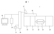
- FIG. 1 is a diagram showing a schematic overall configuration of a liquid chromatograph mass spectrometer.
- FIG. 13 is a diagram showing an example of an apparatus status confirmation screen of the liquid chromatograph mass spectrometer.
- FIG. 13 is a diagram showing an example of a screen for confirming a processed sample in a pretreatment process and an analysis process of the liquid chromatograph mass spectrometer.
- FIG. 13 is a diagram showing an example of a processing sample confirmation screen for a separation column.
- FIG. 13 is a diagram showing an example of a mask setting screen for a separation column.
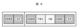
- a typical separation processing scheme in a liquid chromatograph mass spectrometer Separation processing scheme when the solvent ratio is different from the previous measurement. Separation treatment scheme when the previous measurement may cause salt precipitation.
- 3 shows a verification and confirmation flow according to the first embodiment. 13 shows a verification and confirmation flow according to the second embodiment.
- FIG. 13 is a diagram showing an example of an analysis plan schedule that was created at the time of
- Figure 1 is a diagram showing the overall schematic configuration of a liquid chromatograph mass spectrometer.
- the liquid chromatograph mass spectrometer 1 includes a pre-processing section 21, a separation section 22 having a plurality of separation columns 23 for performing separation processing, and an analysis section 24, as well as a sample rack supplying section 25 for supplying sample racks carrying one or more sample containers containing samples to be processed (analyzed) in these processing sections, a transport line 26, an ID reading section 27, an overall management computer 28, etc.
- the sample rack supply unit 25 supplies sample racks that hold a plurality of sample containers.
- the sample containers held by the sample rack are provided with a label or a barcode on which a sample ID indicating attribute information related to the blood sample (reception number, patient name, requested analysis item, etc.) is recorded.
- the sample rack itself is provided with a tag indicating a rack ID indicating rack identification information such as a rack number.
- the sample rack placed in the sample rack supply unit 25 is transported by a transport line 26 . At that time, information regarding the sample ID and the sample rack ID is read by the ID reading unit 27 and sent to the overall management computer 28 .
- the transport line 26 transports the sample racks supplied from the sample rack supply unit 25 to the pre-processing unit 21 in the target liquid chromatograph mass spectrometer 1 in accordance with an analysis request made by a user such as a laboratory technician or doctor.
- the pretreatment section 21 starts processing the transported specimen in accordance with the analysis request.
- the specimen is dispensed, unnecessary substances in the extracted specimen are removed through stirring or magnetic bead processing, etc., and the specimen is diluted according to item, and the processed specimen is transported to the separation section 22.
- a schedule is planned for the order and content of subsequent analyses of the specimen samples processed in the pretreatment unit 21. Subsequent processing is carried out based on the planned schedule.
- the specimen sample transported to the separation section 22 is pumped into each of the multiple separation columns 23 present within the separation section 22 corresponding to the analysis items.
- the specimen sample is entrained in the flow of the mobile phase and passes through the separation columns 23, and the components are separated by utilizing the difference in passing speed.
- the separation columns 23 to which the specimen sample is assigned are determined by a schedule determined at the time of dispensing.
- the specimen sample and mobile phase flow from the separation section 22 via a pump to the ion source of the analysis section 24, the specimen sample is ionized using an ionization method. At this time, only ions with a specific mass-to-charge ratio are selected and measured using a detector. The results measured by the detector are used to calculate the analysis results to be displayed to the user.
- the separation column 23 is a consumable item with a set number of uses and expiration date, and if either the number of uses or the expiration date exceeds the usable range, it becomes unusable (hereinafter referred to as a mask).
- the separation columns 23 have a set expiration date and a set number of times they can be used. Therefore, even when using a multi-stream type liquid chromatograph mass spectrometer 1 such as that of this embodiment, if multiple separation columns 23 need to be replaced at the same or close intervals, sample analysis cannot be continued and the device may be shut down.
- the overall management computer 28 is a computer equipped with a CPU, memory, etc., and performs the necessary control for the analysis work of each device in the liquid chromatograph mass spectrometer 1, such as the sample rack supply unit 25, the transport line 26, the ID reading unit 27, the preprocessing unit 21, the separation unit 22, and the analysis unit 24.
- the overall management computer 28 determines the analysis schedule from the requested analysis items based on the attribute information and device status read by the ID reading unit 27.
- the overall management computer 28 also controls the display of the screen on the display device 30, which displays various information such as information about the sample, information about the analysis items, and information about the analysis results. It also controls the display of various screens related to the operation of the liquid chromatograph mass spectrometer 1, such as an operation screen for starting the analysis, an analysis progress screen, a screen for instructing the use of the separation column 23 corresponding to the analysis item when performing the analysis work, and information about the usage status of the separation column 23.
- This overall management computer 28 corresponds to the control unit.
- the overall management computer 28 determines whether an error has occurred in each of the separation columns 23 (determination step) as a display control for managing sample processing information within the device when analysis is performed, and causes the display section to display a workflow related to the separation section 22, as well as identifying and displaying the separation column 23 determined to have an error and the sample related to that separation column 23 (display step). At this time, the processing status of the identified sample can be displayed.
- the types of errors include, for example, an abnormality occurring in the separation column 23, or an error or a warning that the validity period of the separation column 23 is about to expire.
- the overall management computer 28 identifies and displays the separation column 23 in which the abnormality occurred, and also identifies and displays the samples that are currently using or are scheduled to use the separation column 23 as related samples.
- the abnormality is a warning that the separation column 23 is about to expire
- the separation column 23 to be replaced and the associated samples that are using or are scheduled to use the separation column 23 are identified and displayed. Details of these controls and displays will be described later.
- this overall management computer 28 is connected to an operation unit 29 consisting of a keyboard and mouse for inputting data, a display device 30 for displaying data, and a storage device 31 for storing analysis instruction information and measurement results.
- the display device 30 is a display device such as a liquid crystal display that displays information related to the processing status within the device, including the analysis results, the progress of the analysis, and the usage status of the separation column 23.
- This display device 30 can be a touch panel type, in which case it also serves as the operation unit 29.
- the storage device 31 is a recording medium such as a semiconductor memory, such as a flash memory, or a magnetic disk, such as a HDD, that records data related to the sample input into the liquid chromatograph mass spectrometer 1 and the analysis results.
- This storage device 31 also records various computer programs for controlling the operation of each device in the liquid chromatograph mass spectrometer 1 and for executing various display processes, which will be described later.
- the above is the configuration of the liquid chromatograph mass spectrometer 1.
- the analysis process of a sample using the liquid chromatograph mass spectrometer 1 described above is generally performed in the following order.
- the operator uses the display device 30 and the operation unit 29 to give analysis instructions to the liquid chromatograph mass spectrometer 1.
- the analysis instructions are stored in the storage device 31 and are also sent to the modules (preprocessing unit 21, separation unit 22, and analysis unit 24) via the overall management computer 28.
- the target module performs the analysis operation according to the received instructions.
- FIG. 2 the display flow of the device status confirmation screen 200 will be explained.
- the liquid chromatograph mass spectrometer 1 is controlled by the overall management computer 28, and the device status confirmation screen 200 in FIG. 2 is displayed on the display device 30.
- the operator uses the display device 30 and the operation unit 29 to instruct the liquid chromatograph mass spectrometer 1 to start the device status confirmation screen 200.
- the overall management computer 28 starts automatic confirmation of the device status based on this start instruction.
- the automatic device status check information includes the processing status of the pre-processing unit 21 of the device, the processing status and number of uses of each separation column 23 in the separation unit 22, the processing status of the analysis unit 24, and the estimated scheduled time when the analysis will be completed.
- This process corresponds to a determination step in which it is determined whether or not an error has occurred in each separation column 23.
- the overall management computer 28 determines the colors to be used to gradually display the device status, etc., displayed on the device status confirmation screen 200 shown in FIG. 2 on the display device 30, and issues instructions to use the colors according to the processing status.
- the overall management computer 28 causes the display device 30 to update the device processing status screen and display the device status confirmation screen 200 in FIG. 2.
- the device status confirmation screen 200 in FIG. 2 will be described below.
- the device status confirmation screen 200 shown in FIG. 2 is a screen intended to check the operating status and state of the liquid chromatograph mass spectrometer 1, and to identify the location of any abnormalities that may have occurred.
- the process transition display 204 indicates the order of the analysis steps.
- buttons indicating the device status namely the pretreatment section button 201, the multiple separation column button 202, and the analysis section button 203, are displayed in the following color examples.
- the display can be as follows:
- the number of times the separation column 23 can be used before it becomes unusable is greater than the number of recommended replacement times set for that separation column 23, and the expiration date is earlier than the recommended replacement date, the column is colored green.
- the column is colored yellow.
- a separation column 23 has exceeded the number of uses or expiration date set for that separation column 23, it is colored red. If a process or separation column 23 is not performing processing, it is not colored. If a process or separation column 23 has stopped operating due to a sudden abnormality in the device, such as a clog, it is colored orange. If a separation column 23 is not registered in the device, it is colored black. In addition, the screen is updated based on information from the overall management computer 28 about the start and end of processing in each process and each separation column 23.
- Fig. 3 shows an example of a screen for confirming samples processed in the pre-processing and analysis processes
- Fig. 4 shows an example of a screen for confirming samples processed in the separation column
- Fig. 5 shows an example of a mask setting screen for the separation column.
- the overall management computer 28 displays the sample processing status confirmation screen 300 (FIG. 3) related to the pre-processing section 21.
- This sample processing status confirmation screen 300 as well as the sample processing status confirmation screen 400 and mask setting confirmation screen 500 (FIG. 5) described below, may be displayed by transitioning from the device status confirmation screen 200 or may be displayed as a pop-up on the device status confirmation screen 200, and are not particularly limited.
- the overall management computer 28 displays the sample processing status confirmation screen 400 (FIG. 4) for the separation column 23.
- the sample processing status confirmation screen 400 also displays information related to the separation column 23 that was pressed, and the display content differs depending on each separation column button 202.
- the overall management computer 28 displays a sample processing status confirmation screen 300 for the analysis section 24 as shown in FIG. 3.
- the sample processing status confirmation screen 300 in FIG. 3 and the sample processing status confirmation screen 400 in FIG. 4 show the sample processing status corresponding to the target process or separation column 23 button pressed on the device status confirmation screen 200 in FIG. 2. This process corresponds to the display step of displaying the workflow related to the separation unit 22 on the display unit.
- the operator uses the display device 30 and the operation unit 29 to instruct the liquid chromatograph mass spectrometer 1 to display the sample processing status of the process.
- the overall management computer 28 begins checking the sample processing schedule based on this start instruction.
- the overall management computer 28 performs an automatic check of the device status.
- the overall management computer 28 determines the colors to be used to display the status of the device and the like in stages, which are displayed on the display device 30 as the sample processing status check screen 300 in FIG. 3 and the sample processing status check screen 400 in FIG. 4.
- the overall management computer 28 causes the display device 30 to update the device processing status screen, and displays the sample processing status confirmation screen 300 in FIG. 3 and the sample processing status confirmation screen 400 in FIG. 4.
- sample processing status confirmation screens 300, 400 shown in Figures 3 and 4 will be explained.
- sample processing status confirmation screen 400 shown in Figure 4 will be used, but the contents of the sample processing status confirmation screen 300 are similar.
- sample processing status confirmation screen 400 The purpose of the sample processing status confirmation screen 400 is to confirm information such as the process corresponding to the pressed button on the device status confirmation screen 200 in Figure 2, information on the sample processing status in the separation column 23, and which separation column 23 is scheduled to be used in the separation process.
- the sample processing status confirmation screen 400 in FIG. 4 is also intended to provide the user with information to determine when to replace the separation column 23, and information on the type of each separation column 23.
- the sample processing status confirmation screen 400 in FIG. 4 displays sample processing information 401 (sample processing information 301 in FIG. 3).
- the displayed information includes "sample ID,” "column position” as the connection position of the separation column 23, "processing status” as the sample processing status, and "estimated end time” of the analysis process as the schedule determined by the device when processing began.
- Sample ID is the sample related to the separation column 23 being displayed, and displays the ID of the sample that is using or will be using the corresponding separation column 23.
- the "processing status" is displayed as follows. When the target sample is undergoing processing in the preprocessing process, analysis process, or separation column 23, "Processing in progress” is displayed. When the target sample is undergoing processing in the previous process or separation column 23 and is scheduled to be processed in the process or separation column 23 corresponding to the currently displayed screen, "Planned to be processed” is displayed.
- the status of the device can be displayed by coloring.
- the coloring for each button in Figure 2 can be the same as the coloring for the status.
- the close button 402 (close button 302 in FIG. 3) is a button for closing the sample processing status confirmation screen 400 in FIG. 4 and returning to the device status confirmation screen 200 in FIG. 2.
- Column type 403 is an area that is displayed only on the sample processing status confirmation screen 400 in Figure 4, and is used when checking the type of separation column 23.
- the column type 403 is intended to provide the user with information about the type of separation column 23 when it is replaced. This allows the user to check when replacing with the same type of separation column 23.
- the mask button 404 is a button that is displayed only on the sample processing status confirmation screen 400 in FIG. 4, and is used when displaying the mask setting confirmation screen 500 in FIG. 5 for the corresponding separation column 23.
- the mask setting confirmation screen 500 is displayed, and the mask setting can be performed to make the separation column 23 removable.
- the mask button 404 is used to make the separation column 23 removable in cases where replacement is desired before the automatic mask setting, and is used when performing manual mask setting.
- the device status confirmation screen 200 shown in FIG. 2 will be displayed in color to indicate that operation has stopped.
- the sample processing information 401 on the sample processing status confirmation screen 400 that is displayed will show that "abnormality has occurred” in “Processing status” and no time is displayed in "Estimated end time”.
- the "sample ID" can be used to identify samples that are currently using the separation column 23 and samples that are scheduled to be used as related samples.
- a mask setting confirmation screen 500 such as that shown in FIG. 5 can be displayed.
- the remaining number of times the column can be used 405 is an area that is displayed only on the sample processing status confirmation screen 400 in FIG. 4, and is used when checking the remaining number of times the separation column 23 can be used.
- the remaining number of times that the column can be used 405 is calculated based on the number of effective uses set for the separation column 23 and the number of times that the separation column 23 has been used. This can be provided to the user as information for determining when to replace the separation column 23. Note that in this embodiment, the number of times is displayed as a percentage, but it is also possible to display the remaining number of effective uses itself.
- the remaining column usage count 405 on the sample processing status confirmation screen 400 in FIG. 4 makes it possible to prompt the user to replace the separation column 23 before it becomes masked, and to carry out the replacement.
- sample processing status confirmation screen 300 in FIG. 3 and the sample processing status confirmation screen 400 in FIG. 4 can inform the user of the status and reservation status of each step and sample processing in each separation column 23 for each sample ID using sample processing information 401 (sample processing information 301 in FIG. 3).
- the sample processing status confirmation screen 400 in FIG. 4 is a display that allows confirmation of the sample processing flow, confirmation of the separation column 23 to be used, the device status, the expected time for completion of sample processing, etc., not just when an abnormality occurs, and can be checked during analysis.
- sample processing status confirmation screen 300 in FIG. 3 is a display that allows confirmation of the sample processing flow, the device status, the expected end time of sample processing, etc., not only when an abnormality occurs, but also for the preprocessing unit 21 and the analysis unit 24, and can be checked when the analysis is being performed.
- Figure 6 shows the scheme of separation processing in a liquid chromatograph mass spectrometer.
- a typical separation process has four major steps: an equilibration step in which a solvent is passed through the separation column so that it is distributed throughout the column; a separation step in which a sample is injected into the separation column after equilibration; an MS section introduction step in which the sample separated based on the elution time is introduced into the mass spectrometer; and a cleaning step in which the inside of the MS section is cleaned.
- Figure 7 shows the separation process steps when the solvent ratio (for example, the ratio of water to acetonitrile when performing gradient elution in reversed phase mode, changing the water/acetonitrile composition from 90/10 to 50/50) is different from the previous measurement.
- the solvent ratio for example, the ratio of water to acetonitrile when performing gradient elution in reversed phase mode, changing the water/acetonitrile composition from 90/10 to 50/50
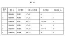
- Figure 11 shows an example of the analysis processes planned at the time of an analysis request, their order, and information on the separation columns to be used in the analysis. Based on this information, the liquid chromatograph mass spectrometer schedules solvent replacement, equilibration, cleaning, etc.
- Figure 9 shows the flow for confirming the analysis plan.
- the analysis process for the previous measurement, its order, and information on the separation column to be used in the analysis are stored (S901). Note that in the flowchart, the "S” that stands for “step” is omitted and only the number is used. The same is true for Figure 10.
- the separation process is planned according to the relationship between the previous and next analyses (S903).
- the planned information is stored (S904).
- the information stored in S904 is stored in a first storage unit provided in part of the storage area of storage device 31 in FIG. 1. Note that although hereinafter these are referred to as the "first storage unit” and the "second storage unit", the storage devices do not need to be separate hardware devices. For example, even if the storage area of a single hard disk storage device is divided into a "first storage area” and a "second storage area” in software, this also corresponds to the "first storage unit” and "second storage unit” as referred to in the claims.
- the example shown by the dotted arrow on the right is an example where the separation process is consecutive and uses the same solvent, so solvent replacement and cleaning after solvent replacement are not required.
- the information on the separation process at the time of planning is read from the memory unit before the measurement (S905), and the information stored as the current separation process is read (S906).
- the information read in S906 is information stored in a second memory unit provided as part of the memory area of the memory device 31 in FIG. 1.
- the notification unit notifies the mismatch (S908) and searches for other separation columns (streams) that can be analyzed under the same analysis conditions as the separation process at the time of planning (S909).
- the display device 30 is used as the notification unit. If the comparison unit determines that there is a mismatch, the display device 30 displays the mismatch on its display screen to notify the operator. As a method of notification, an alarm may be sounded from a speaker attached to the display device to attract the operator's attention.
- the analysis plan is changed to analyze that stream and the analysis continues (Y: Yes). If there is no stream that can be analyzed, the analysis is interrupted (N: No). After going through this process, the analysis is performed and the analysis results are output (S910).
- Steps S1001 to S1009 are the same as those in FIG. 9, so the description will be omitted.
- the determination unit determines which cleaning operation to use to clean the analysis column, etc. (S1010). After executing the cleaning operation determined by the determination unit, the analysis and results are output (S1011).
- analysis cannot start until the cleaning operation is completed, so it takes longer to output the analysis results than in Example 1, but it is faster than interrupting the analysis. If the specimen does not require a long time, it is useful to select the embodiment of Example 2.
- Example 1 or Example 2 it may be possible to set whether to apply Example 1 or Example 2 to all samples at once, or it may be possible to automatically change the mode applied depending on the type of sample, such as applying Example 2 to emergency samples but Example 1 to general samples.
Landscapes
- Physics & Mathematics (AREA)
- Health & Medical Sciences (AREA)
- Life Sciences & Earth Sciences (AREA)
- Chemical & Material Sciences (AREA)
- Analytical Chemistry (AREA)
- Biochemistry (AREA)
- General Health & Medical Sciences (AREA)
- General Physics & Mathematics (AREA)
- Immunology (AREA)
- Pathology (AREA)
- Other Investigation Or Analysis Of Materials By Electrical Means (AREA)
Abstract
Priority Applications (2)
| Application Number | Priority Date | Filing Date | Title |
|---|---|---|---|
| JP2025531449A JPWO2025009341A1 (fr) | 2023-07-04 | 2024-06-11 | |
| CN202480039847.2A CN121311763A (zh) | 2023-07-04 | 2024-06-11 | 液相色谱装置及其控制方法 |
Applications Claiming Priority (2)
| Application Number | Priority Date | Filing Date | Title |
|---|---|---|---|
| JP2023-109841 | 2023-07-04 | ||
| JP2023109841 | 2023-07-04 |
Publications (1)
| Publication Number | Publication Date |
|---|---|
| WO2025009341A1 true WO2025009341A1 (fr) | 2025-01-09 |
Family
ID=94171721
Family Applications (1)
| Application Number | Title | Priority Date | Filing Date |
|---|---|---|---|
| PCT/JP2024/021254 Ceased WO2025009341A1 (fr) | 2023-07-04 | 2024-06-11 | Dispositif de chromatographie en phase liquide et procédé de commande pour celui-ci |
Country Status (3)
| Country | Link |
|---|---|
| JP (1) | JPWO2025009341A1 (fr) |
| CN (1) | CN121311763A (fr) |
| WO (1) | WO2025009341A1 (fr) |
Citations (7)
| Publication number | Priority date | Publication date | Assignee | Title |
|---|---|---|---|---|
| WO2014068786A1 (fr) * | 2012-11-05 | 2014-05-08 | 株式会社島津製作所 | Dispositif d'analyse chromatographique |
| JP2014228289A (ja) | 2013-05-20 | 2014-12-08 | 株式会社日立ハイテクノロジーズ | 自動分析装置および分析方法 |
| JP2019505773A (ja) * | 2015-12-18 | 2019-02-28 | エフ ホフマン−ラ ロッシュ アクチェン ゲゼルシャフト | 自動化された臨床診断システムおよび方法 |
| JP2020193815A (ja) * | 2019-05-24 | 2020-12-03 | 株式会社島津製作所 | クロマトグラフおよびクロマトグラフのカラム選択方法 |
| JP2022075478A (ja) * | 2020-11-05 | 2022-05-18 | 株式会社島津製作所 | 分析システムおよび分析方法 |
| WO2022124187A1 (fr) * | 2020-12-11 | 2022-06-16 | 株式会社日立ハイテク | Procédé de commande de dispositif d'analyse automatisé |
| WO2022185682A1 (fr) * | 2021-03-03 | 2022-09-09 | 株式会社日立ハイテク | Procédé de commande de dispositif de spectrométrie de masse de chromatographe en phase liquide et dispositif de spectrométrie de masse de chromatographe en phase liquide |
-
2024
- 2024-06-11 WO PCT/JP2024/021254 patent/WO2025009341A1/fr not_active Ceased
- 2024-06-11 JP JP2025531449A patent/JPWO2025009341A1/ja active Pending
- 2024-06-11 CN CN202480039847.2A patent/CN121311763A/zh active Pending
Patent Citations (7)
| Publication number | Priority date | Publication date | Assignee | Title |
|---|---|---|---|---|
| WO2014068786A1 (fr) * | 2012-11-05 | 2014-05-08 | 株式会社島津製作所 | Dispositif d'analyse chromatographique |
| JP2014228289A (ja) | 2013-05-20 | 2014-12-08 | 株式会社日立ハイテクノロジーズ | 自動分析装置および分析方法 |
| JP2019505773A (ja) * | 2015-12-18 | 2019-02-28 | エフ ホフマン−ラ ロッシュ アクチェン ゲゼルシャフト | 自動化された臨床診断システムおよび方法 |
| JP2020193815A (ja) * | 2019-05-24 | 2020-12-03 | 株式会社島津製作所 | クロマトグラフおよびクロマトグラフのカラム選択方法 |
| JP2022075478A (ja) * | 2020-11-05 | 2022-05-18 | 株式会社島津製作所 | 分析システムおよび分析方法 |
| WO2022124187A1 (fr) * | 2020-12-11 | 2022-06-16 | 株式会社日立ハイテク | Procédé de commande de dispositif d'analyse automatisé |
| WO2022185682A1 (fr) * | 2021-03-03 | 2022-09-09 | 株式会社日立ハイテク | Procédé de commande de dispositif de spectrométrie de masse de chromatographe en phase liquide et dispositif de spectrométrie de masse de chromatographe en phase liquide |
Also Published As
| Publication number | Publication date |
|---|---|
| CN121311763A (zh) | 2026-01-09 |
| JPWO2025009341A1 (fr) | 2025-01-09 |
Similar Documents
| Publication | Publication Date | Title |
|---|---|---|
| US20130011298A1 (en) | Sample analyzer and storage medium | |
| JP5134931B2 (ja) | 自動分析装置 | |
| JP6117310B2 (ja) | 自動分析装置 | |
| JP7227948B2 (ja) | 分析装置の状態を点検するための技術 | |
| EP2116852B1 (fr) | Analyseur automatique | |
| JP2010151707A (ja) | 自動分析装置、その支援システム | |
| US11971424B2 (en) | Automatic analyzer | |
| WO2012120755A1 (fr) | Dispositif d'analyse | |
| US12339655B2 (en) | Automatic analysis device and maintenance guide method in automatic analysis device | |
| JP5808582B2 (ja) | 自動分析装置 | |
| JPWO2016140017A1 (ja) | 自動分析装置 | |
| JP2020204610A (ja) | 診断検査の有効性を判断するために対照試料を供給する方法および実験室システム | |
| JP2009270841A (ja) | 自動分析装置 | |
| JP2006189282A (ja) | 自動分析装置 | |
| US12123884B2 (en) | Monitoring the cleaning status of an automatic analyzer | |
| WO2019198345A1 (fr) | Dispositif d'analyse automatique | |
| CN103257243A (zh) | 自动分析装置 | |
| WO2025009341A1 (fr) | Dispositif de chromatographie en phase liquide et procédé de commande pour celui-ci | |
| JP2024081805A (ja) | 液体クロマトグラフ質量分析装置の制御方法、および液体クロマトグラフ質量分析装置 | |
| JP7174066B2 (ja) | 自動分析装置 | |
| JP5658904B2 (ja) | 検体分析装置及び分析制御プログラム | |
| WO2021140741A1 (fr) | Dispositif d'analyse automatique, système d'affichage de dispositif d'analyse automatique et procédé de réalisation d'affichage dans un dispositif d'analyse automatique | |
| JP4619892B2 (ja) | 自動分析装置 | |
| JP7342122B2 (ja) | 自動分析装置および自動分析装置の表示装置の表示方法 | |
| EP4266059A1 (fr) | Procédé de contrôle de dispositif de prétraitement d'échantillons |
Legal Events
| Date | Code | Title | Description |
|---|---|---|---|
| 121 | Ep: the epo has been informed by wipo that ep was designated in this application |
Ref document number: 24835858 Country of ref document: EP Kind code of ref document: A1 |
|
| DPE1 | Request for preliminary examination filed after expiration of 19th month from priority date (pct application filed from 20040101) | ||
| ENP | Entry into the national phase |
Ref document number: 2025531449 Country of ref document: JP Kind code of ref document: A |
|
| WWE | Wipo information: entry into national phase |
Ref document number: 2024835858 Country of ref document: EP |
|
| NENP | Non-entry into the national phase |
Ref country code: DE |
|
| ENP | Entry into the national phase |
Ref document number: 2024835858 Country of ref document: EP Effective date: 20260204 |