WO2025009938A1 - 영상 부호화/복호화 방법, 비트스트림을 저장한 기록 매체 및 비트스트림을 전송하는 방법 - Google Patents

영상 부호화/복호화 방법, 비트스트림을 저장한 기록 매체 및 비트스트림을 전송하는 방법 Download PDF

Info

Publication number
WO2025009938A1
WO2025009938A1 PCT/KR2024/009604 KR2024009604W WO2025009938A1 WO 2025009938 A1 WO2025009938 A1 WO 2025009938A1 KR 2024009604 W KR2024009604 W KR 2024009604W WO 2025009938 A1 WO2025009938 A1 WO 2025009938A1
Authority
WO
WIPO (PCT)
Prior art keywords
nnpf
target
nnpfc
nnpfa
sei message
Prior art date
Legal status (The legal status is an assumption and is not a legal conclusion. Google has not performed a legal analysis and makes no representation as to the accuracy of the status listed.)
Ceased
Application number
PCT/KR2024/009604
Other languages
English (en)
French (fr)
Inventor
탄핸드리
Current Assignee (The listed assignees may be inaccurate. Google has not performed a legal analysis and makes no representation or warranty as to the accuracy of the list.)
LG Electronics Inc
Original Assignee
LG Electronics Inc
Priority date (The priority date is an assumption and is not a legal conclusion. Google has not performed a legal analysis and makes no representation as to the accuracy of the date listed.)
Filing date
Publication date
Application filed by LG Electronics Inc filed Critical LG Electronics Inc
Priority to KR1020257018698A priority Critical patent/KR20250108655A/ko
Priority to CN202480005400.3A priority patent/CN120345242A/zh
Publication of WO2025009938A1 publication Critical patent/WO2025009938A1/ko
Priority to US19/219,704 priority patent/US20250286998A1/en
Priority to MX2025006609A priority patent/MX2025006609A/es
Anticipated expiration legal-status Critical
Ceased legal-status Critical Current

Links

Images

Classifications

    • HELECTRICITY
    • H04ELECTRIC COMMUNICATION TECHNIQUE
    • H04NPICTORIAL COMMUNICATION, e.g. TELEVISION
    • H04N19/00Methods or arrangements for coding, decoding, compressing or decompressing digital video signals
    • H04N19/10Methods or arrangements for coding, decoding, compressing or decompressing digital video signals using adaptive coding
    • H04N19/102Methods or arrangements for coding, decoding, compressing or decompressing digital video signals using adaptive coding characterised by the element, parameter or selection affected or controlled by the adaptive coding
    • H04N19/117Filters, e.g. for pre-processing or post-processing
    • GPHYSICS
    • G06COMPUTING OR CALCULATING; COUNTING
    • G06NCOMPUTING ARRANGEMENTS BASED ON SPECIFIC COMPUTATIONAL MODELS
    • G06N3/00Computing arrangements based on biological models
    • G06N3/02Neural networks
    • GPHYSICS
    • G06COMPUTING OR CALCULATING; COUNTING
    • G06NCOMPUTING ARRANGEMENTS BASED ON SPECIFIC COMPUTATIONAL MODELS
    • G06N3/00Computing arrangements based on biological models
    • G06N3/02Neural networks
    • G06N3/04Architecture, e.g. interconnection topology
    • HELECTRICITY
    • H04ELECTRIC COMMUNICATION TECHNIQUE
    • H04NPICTORIAL COMMUNICATION, e.g. TELEVISION
    • H04N19/00Methods or arrangements for coding, decoding, compressing or decompressing digital video signals
    • H04N19/10Methods or arrangements for coding, decoding, compressing or decompressing digital video signals using adaptive coding
    • H04N19/134Methods or arrangements for coding, decoding, compressing or decompressing digital video signals using adaptive coding characterised by the element, parameter or criterion affecting or controlling the adaptive coding
    • H04N19/136Incoming video signal characteristics or properties
    • HELECTRICITY
    • H04ELECTRIC COMMUNICATION TECHNIQUE
    • H04NPICTORIAL COMMUNICATION, e.g. TELEVISION
    • H04N19/00Methods or arrangements for coding, decoding, compressing or decompressing digital video signals
    • H04N19/10Methods or arrangements for coding, decoding, compressing or decompressing digital video signals using adaptive coding
    • H04N19/169Methods or arrangements for coding, decoding, compressing or decompressing digital video signals using adaptive coding characterised by the coding unit, i.e. the structural portion or semantic portion of the video signal being the object or the subject of the adaptive coding
    • H04N19/17Methods or arrangements for coding, decoding, compressing or decompressing digital video signals using adaptive coding characterised by the coding unit, i.e. the structural portion or semantic portion of the video signal being the object or the subject of the adaptive coding the unit being an image region, e.g. an object
    • H04N19/172Methods or arrangements for coding, decoding, compressing or decompressing digital video signals using adaptive coding characterised by the coding unit, i.e. the structural portion or semantic portion of the video signal being the object or the subject of the adaptive coding the unit being an image region, e.g. an object the region being a picture, frame or field
    • HELECTRICITY
    • H04ELECTRIC COMMUNICATION TECHNIQUE
    • H04NPICTORIAL COMMUNICATION, e.g. TELEVISION
    • H04N19/00Methods or arrangements for coding, decoding, compressing or decompressing digital video signals
    • H04N19/10Methods or arrangements for coding, decoding, compressing or decompressing digital video signals using adaptive coding
    • H04N19/169Methods or arrangements for coding, decoding, compressing or decompressing digital video signals using adaptive coding characterised by the coding unit, i.e. the structural portion or semantic portion of the video signal being the object or the subject of the adaptive coding
    • H04N19/184Methods or arrangements for coding, decoding, compressing or decompressing digital video signals using adaptive coding characterised by the coding unit, i.e. the structural portion or semantic portion of the video signal being the object or the subject of the adaptive coding the unit being bits, e.g. of the compressed video stream
    • HELECTRICITY
    • H04ELECTRIC COMMUNICATION TECHNIQUE
    • H04NPICTORIAL COMMUNICATION, e.g. TELEVISION
    • H04N19/00Methods or arrangements for coding, decoding, compressing or decompressing digital video signals
    • H04N19/42Methods or arrangements for coding, decoding, compressing or decompressing digital video signals characterised by implementation details or hardware specially adapted for video compression or decompression, e.g. dedicated software implementation
    • HELECTRICITY
    • H04ELECTRIC COMMUNICATION TECHNIQUE
    • H04NPICTORIAL COMMUNICATION, e.g. TELEVISION
    • H04N19/00Methods or arrangements for coding, decoding, compressing or decompressing digital video signals
    • H04N19/46Embedding additional information in the video signal during the compression process
    • HELECTRICITY
    • H04ELECTRIC COMMUNICATION TECHNIQUE
    • H04NPICTORIAL COMMUNICATION, e.g. TELEVISION
    • H04N19/00Methods or arrangements for coding, decoding, compressing or decompressing digital video signals
    • H04N19/70Methods or arrangements for coding, decoding, compressing or decompressing digital video signals characterised by syntax aspects related to video coding, e.g. related to compression standards
    • HELECTRICITY
    • H04ELECTRIC COMMUNICATION TECHNIQUE
    • H04NPICTORIAL COMMUNICATION, e.g. TELEVISION
    • H04N19/00Methods or arrangements for coding, decoding, compressing or decompressing digital video signals
    • H04N19/80Details of filtering operations specially adapted for video compression, e.g. for pixel interpolation
    • H04N19/82Details of filtering operations specially adapted for video compression, e.g. for pixel interpolation involving filtering within a prediction loop
    • HELECTRICITY
    • H04ELECTRIC COMMUNICATION TECHNIQUE
    • H04NPICTORIAL COMMUNICATION, e.g. TELEVISION
    • H04N19/00Methods or arrangements for coding, decoding, compressing or decompressing digital video signals
    • H04N19/85Methods or arrangements for coding, decoding, compressing or decompressing digital video signals using pre-processing or post-processing specially adapted for video compression

Definitions

  • the present disclosure relates to a method for encoding/decoding a video, a recording medium storing a bitstream, and a method for transmitting the bitstream, and more particularly, to a method for determining whether to cancel persistence of a neural network post-filter.
  • HD High Definition
  • UHD Ultra High Definition
  • the present disclosure aims to provide a video encoding/decoding method and device with improved encoding/decoding efficiency.
  • the present disclosure aims to provide a method for clearly distinguishing which NNPF's persistence is to be canceled when two or more NNPF activations with the same identification information exist.
  • the present disclosure aims to provide a method for preventing simultaneous activation of two or more NNPFs having the same identification information.
  • the present disclosure aims to provide a non-transitory computer-readable recording medium storing a bitstream generated by an image encoding method according to the present disclosure.
  • the present disclosure aims to provide a method for transmitting a bitstream generated by an image encoding method according to the present disclosure.
  • the present disclosure aims to provide a non-transitory computer-readable recording medium that stores a bitstream received and decoded by an image decoding device according to the present disclosure and used for restoring an image.
  • An image decoding method is an image decoding method performed by an image decoding device, comprising: a step of obtaining an NNPF (neural-network post-filter) SEI (supplemental enhancement information) message, wherein the NNPF SEI message includes an NNPFC (neural-network post-filter characteristics) SEI message and an NNPFA (neural-network post-filter activation) SEI message, and determining a neural network that can be used as a post-processing filter based on the NNPFC SEI message; And based on the NNPFA SEI message, a step of determining whether to activate a target NNPF applicable to the current picture, wherein the target NNPF is used to perform post-processing filtering on the current picture and subsequent pictures in the current layer in the output order until a picture of the current layer related to an NNPFA SEI message having the same target NNPF identification information as the current SEI message is output next to the current picture in the output order.
  • NNPF neural-network post-filter
  • an image encoding method is provided, which is performed by an image encoding device, comprising: a step of encoding a neural network that can be used as a post-processing filter into a neural-network post-filter characteristics (NNPFC) SEI (supplemental enhancement information) message; and a step of encoding whether a target NNPF that can be applied to a current picture is activated into a neural-network post-filter activation (NNPFA) SEI message, wherein the target NNPF is used to perform post-processing filtering on the current picture and subsequent pictures in the current layer in the output order until a picture of the current layer related to an NNPFA SEI message having the same target NNPF identification information as the current SEI message is output next to the current picture in the output order.
  • NNPFC neural-network post-filter characteristics
  • NNPFA neural-network post-filter activation
  • a computer-readable recording medium can store a bitstream generated by an image encoding method or device of the present disclosure.
  • a transmission method can transmit a bitstream generated by an image encoding method or device of the present disclosure.
  • a video encoding/decoding method and device with improved encoding/decoding efficiency can be provided.
  • a non-transitory computer-readable recording medium storing a bitstream generated by an image encoding method according to the present disclosure can be provided.
  • a non-transitory computer-readable recording medium can be provided that stores a bitstream received and decoded by an image decoding device according to the present disclosure and used for restoring an image.
  • a method for transmitting a bitstream generated by an image encoding method can be provided.
  • FIG. 1 is a diagram schematically illustrating a video coding system to which an embodiment according to the present disclosure can be applied.
  • FIG. 2 is a drawing schematically showing an image encoding device to which an embodiment according to the present disclosure can be applied.
  • FIG. 3 is a diagram schematically illustrating an image decoding device to which an embodiment according to the present disclosure can be applied.
  • Figure 4 illustrates an example of a hierarchical structure for coded video/images.
  • Figure 5 is a diagram explaining an interleaved method for deriving a luma channel.
  • Figure 6 is a drawing for explaining an image encoding method of an image encoding device.
  • Figure 7 is a drawing for explaining an image decoding method of an image decoding device.
  • FIG. 8 is a diagram for explaining an image decoding method for an embodiment of determining whether a target NNPF is activated.
  • Figures 9 to 11 are diagrams for explaining various embodiments of whether to cancel the persistence of the target NNPF.
  • FIG. 12 is a drawing exemplarily showing a content streaming system to which an embodiment according to the present disclosure can be applied.
  • a component when a component is said to be “connected,” “coupled,” or “connected” to another component, this may include not only a direct connection relationship, but also an indirect connection relationship in which another component exists in between.
  • a component when a component is said to "include” or “have” another component, this does not exclude the other component unless specifically stated otherwise, but means that the other component may be included.
  • first, second, etc. are used only for the purpose of distinguishing one component from another component, and do not limit the order or importance among the components unless specifically stated otherwise. Accordingly, within the scope of this disclosure, a first component in one embodiment may be referred to as a second component in another embodiment, and similarly, a second component in one embodiment may be referred to as a first component in another embodiment.
  • the components that are distinguished from each other are intended to clearly explain the characteristics of each, and do not necessarily mean that the components are separated. That is, a plurality of components may be integrated to form a single hardware or software unit, or a single component may be distributed to form a plurality of hardware or software units. Accordingly, even if not mentioned separately, such integrated or distributed embodiments are also included in the scope of the present disclosure.
  • the components described in various embodiments do not necessarily mean essential components, and some may be optional components. Accordingly, an embodiment that consists of a subset of the components described in one embodiment is also included in the scope of the present disclosure. In addition, an embodiment that includes other components in addition to the components described in various embodiments is also included in the scope of the present disclosure.
  • the present disclosure relates to encoding and decoding of video.
  • the methods and embodiments disclosed in this document can be applied to methods disclosed in the versatile video coding (VVC) standard, the essential video coding (EVC) standard, the AOMedia Video 1 (AV1) standard, the 2nd generation of audio video coding standard (AVS2) or the next generation video/image coding standard (e.g., H.267 or H.268, etc.).
  • VVC versatile video coding
  • EVC essential video coding
  • AV1 AOMedia Video 1
  • AVS2 2nd generation of audio video coding standard
  • next generation video/image coding standard e.g., H.267 or H.268, etc.
  • the present disclosure presents various embodiments relating to video/image coding, and unless otherwise stated, the embodiments may be performed in combination with each other.
  • a "picture” generally means a unit representing one image of a specific time period
  • a slice/tile is a coding unit constituting a part of a picture
  • one picture may be composed of one or more slices/tiles.
  • a slice/tile may include one or more CTUs (coding tree units).
  • One picture may be composed of one or more tile groups.
  • One tile group may include one or more tiles.
  • a brick may represent a rectangular area of CTU rows of tiles in a picture.
  • tile group and slice may be used interchangeably.
  • a tile group/tile group header may be called a slice/slice header.
  • pixel or “pel” may mean the smallest unit that constitutes a picture (or image).
  • sample may be used as a term corresponding to a pixel.
  • a sample may generally represent a pixel or a pixel value, and may represent only a pixel/pixel value of a luma component, or only a pixel/pixel value of a chroma component.
  • a "unit” may represent a basic unit of image processing.
  • a unit may include at least one of a specific region of a picture and information related to the region.
  • One unit may include one luma block and two chroma (e.g., cb, cr) blocks.
  • the unit may be used interchangeably with terms such as "sample array", “block” or “area” depending on the case.
  • an M ⁇ N block may include a set (or array) of samples (or sample array) or transform coefficients consisting of M columns and N rows.
  • the "current block” may mean one of the “current coding block", the “current coding unit”, the “encoding target block”, the “decoding target block” or the “processing target block”.
  • the “current block” may mean the “current prediction block” or the “prediction target block”.
  • transformation inverse transformation
  • quantization inverse quantization
  • the "current block” may mean the “current transformation block” or the “transformation target block”.
  • filtering is performed, the "current block” may mean the "filtering target block”.
  • a "current block” may mean a block including both a luma component block and a chroma component block, or a "luma block of the current block” unless explicitly described as a chroma block.
  • the luma component block of the current block may be explicitly expressed by including an explicit description of the luma component block, such as “luma block” or “current luma block”.
  • the chroma component block of the current block may be explicitly expressed by including an explicit description of the chroma component block, such as "chroma block” or "current chroma block”.
  • FIG. 1 is a diagram schematically illustrating a video coding system to which an embodiment according to the present disclosure can be applied.
  • a video coding system may include an encoding device (10) and a decoding device (20).
  • the encoding device (10) may transmit encoded video and/or image information or data to the decoding device (20) in the form of a file or streaming through a digital storage medium or a network.
  • An encoding device (10) may include a video source generating unit (11), an encoding unit (12), and a transmitting unit (13).
  • a decoding device (20) may include a receiving unit (21), a decoding unit (22), and a rendering unit (23).
  • the encoding unit (12) may be called a video/image encoding unit, and the decoding unit (22) may be called a video/image decoding unit.
  • the transmitting unit (13) may be included in the encoding unit (12).
  • the receiving unit (21) may be included in the decoding unit (22).
  • the rendering unit (23) may include a display unit, and the display unit may be configured as a separate device or an external component.
  • the video source generation unit (11) can obtain a video/image through a process of capturing, synthesizing, or generating a video/image.
  • the video source generation unit (11) can include a video/image capture device and/or a video/image generation device.
  • the video/image capture device can include, for example, one or more cameras, a video/image archive including previously captured video/image, etc.
  • the video/image generation device can include, for example, a computer, a tablet, a smartphone, etc., and can (electronically) generate a video/image.
  • a virtual video/image can be generated through a computer, etc., and in this case, the video/image capture process can be replaced with a process of generating related data.
  • the encoding unit (12) can encode input video/image.
  • the encoding unit (12) can perform a series of procedures such as prediction, transformation, and quantization for compression and encoding efficiency.
  • the encoding unit (12) can output encoded data (encoded video/image information) in the form of a bitstream.
  • the transmission unit (13) can obtain encoded video/image information or data output in the form of a bitstream, and can transmit it to the reception unit (21) of the decoding device (20) or another external object through a digital storage medium or a network in the form of a file or streaming.
  • the digital storage medium can include various storage media such as USB, SD, CD, DVD, Blu-ray, HDD, SSD, etc.
  • the transmission unit (13) can include an element for generating a media file through a predetermined file format, and can include an element for transmission through a broadcasting/communication network.
  • the transmission unit (13) can be provided as a separate transmission device from the encoding device (12), and in this case, the transmission device can include at least one processor for obtaining encoded video/image information or data output in the form of a bitstream, and a transmission unit for transmitting it in the form of a file or streaming.
  • the reception unit (21) can extract/receive the bitstream from the storage medium or the network and transmit it to the decoding unit (22).
  • the decoding unit (22) can decode video/image by performing a series of procedures such as inverse quantization, inverse transformation, and prediction corresponding to the operation of the encoding unit (12).
  • the rendering unit (23) can render the decrypted video/image.
  • the rendered video/image can be displayed through the display unit.
  • FIG. 2 is a diagram schematically illustrating an image encoding device to which an embodiment according to the present disclosure can be applied.
  • the image encoding device (200) may be configured to include an image partitioner (210), a prediction unit (predictor) 220, a residual processor (residual processor) 230, an entropy encoder (entropy encoder) 240, an adder (adder) 250, a filter (filter) 260, and a memory (memory) 270.
  • the prediction unit (220) may include an inter prediction unit (221) and an intra prediction unit (222).
  • the residual processor (230) may include a transformer (transformer) 232, a quantizer (quantizer) 233, a dequantizer (dequantizer) 234, and an inverse transformer (inverse transformer) 235.
  • the residual processing unit (230) may further include a subtractor (231).
  • the adding unit (250) may be called a reconstructor or a reconstructed block generator.
  • the image segmenting unit (210), the prediction unit (220), the residual processing unit (230), the entropy encoding unit (240), the adding unit (250), and the filtering unit (260) described above may be configured by one or more hardware components (e.g., an encoder chipset or a processor) according to an embodiment.
  • the memory (270) may include a DPB (Decoded Picture Buffer) and may be configured by a digital storage medium.
  • the hardware component may further include the memory (270) as an internal/external component.
  • the image segmentation unit (210) can segment an input image (or picture, frame) input to the image encoding device (200) into one or more processing units.
  • the processing unit may be called a coding unit (CU).
  • the coding unit may be obtained by recursively segmenting a coding tree unit (CTU) or a largest coding unit (LCU) according to a QT/BT/TT (Quad-tree/binary-tree/ternary-tree) structure.
  • CTU coding tree unit
  • LCU largest coding unit
  • QT/BT/TT Quad-tree/binary-tree/ternary-tree
  • one coding unit may be segmented into a plurality of coding units of deeper depth based on a quad-tree structure, a binary-tree structure, and/or a ternary-tree structure.
  • the quad-tree structure may be applied first, and the binary-tree structure and/or the ternary-tree structure may be applied later.
  • the coding procedure according to the present disclosure may be performed based on a final coding unit that is no longer segmented. In this case, based on coding efficiency according to image characteristics, etc., the maximum coding unit may be used as the final coding unit, or, if necessary, the maximum coding unit may be recursively divided into coding units of lower depths, and the coding unit of the optimal size may be used as the final coding unit.
  • the coding procedure may include procedures such as prediction, transformation, and/or restoration described below.
  • the processing unit of the coding procedure may be a prediction unit (PU) or a transformation unit (TU).
  • the prediction unit and the transformation unit may be divided or partitioned from the final coding unit, respectively.
  • the prediction unit may be a unit of sample prediction
  • the transformation unit may be a unit for deriving a transform coefficient and/or a unit for deriving a residual signal from a transform coefficient.
  • the video encoding device (200) can generate a residual signal (residual block, residual sample array) by subtracting a prediction signal (predicted block, prediction sample array) output from an inter prediction unit (221) or an intra prediction unit (222) from an input video signal (original block, original sample array), and the generated residual signal is transmitted to a conversion unit (232).
  • a unit that subtracts a prediction signal (prediction block, prediction sample array) from an input video signal (original block, original sample array) within the video encoding device (200) may be called a subtraction unit (231).
  • the prediction unit (220) can perform prediction on a block to be processed (current block) and generate a predicted block including prediction samples for the current block.
  • the prediction unit (220) can determine whether intra prediction or inter prediction is applied per current block or CU unit.
  • the prediction unit (220) can generate various information regarding the prediction of the current block and transmit it to the entropy encoding unit (240).
  • the information regarding the prediction can be encoded in the entropy encoding unit (240) and output in the form of a bitstream.
  • the intra prediction unit (222) can predict the current block by referring to samples in the current picture.
  • the referenced samples may be located in the neighborhood of the current block or may be located away from it depending on the intra prediction mode and/or the intra prediction technique.
  • the intra prediction modes may include a plurality of non-directional modes and a plurality of directional modes.
  • the non-directional mode may include, for example, a DC mode and a planar mode.
  • the directional mode may include, for example, 33 directional prediction modes or 65 directional prediction modes depending on the degree of detail of the prediction direction. However, this is only an example, and a number of directional prediction modes greater or less than that may be used depending on the setting.
  • the intra prediction unit (222) may also determine the prediction mode applied to the current block by using the prediction mode applied to the neighboring block.
  • the inter prediction unit (221) can derive a predicted block for a current block based on a reference block (reference sample array) specified by a motion vector on a reference picture.
  • the motion information can be predicted in units of blocks, subblocks, or samples based on the correlation of motion information between neighboring blocks and the current block.
  • the motion information can include a motion vector and a reference picture index.
  • the motion information can further include information on an inter prediction direction (such as L0 prediction, L1 prediction, or Bi prediction).
  • neighboring blocks can include spatial neighboring blocks existing in the current picture and temporal neighboring blocks existing in the reference picture.
  • the reference picture including the reference block and the reference picture including the temporal neighboring block may be the same or different from each other.
  • the temporal neighboring blocks may be called collocated reference blocks, collocated CUs (colCUs), etc.
  • the reference picture including the temporal neighboring block may be called a collocated picture (colPic).
  • the inter prediction unit (221) may configure a motion information candidate list based on the neighboring blocks, and generate information indicating which candidate is used to derive the motion vector and/or reference picture index of the current block. Inter prediction may be performed based on various prediction modes, and for example, in the case of the skip mode and the merge mode, the inter prediction unit (221) may use the motion information of the neighboring block as the motion information of the current block.
  • the motion vector of the current block may be signaled by using the motion vector of the neighboring block as a motion vector predictor, and encoding an indicator for the motion vector difference and the motion vector predictor.
  • Motion vector difference can mean the difference between the motion vector of the current block and the motion vector predictor.
  • the prediction unit (220) can generate a prediction signal based on various prediction methods and/or prediction techniques described below.
  • the prediction unit (220) can apply intra prediction or inter prediction to predict the current block, and can also apply intra prediction and inter prediction simultaneously.
  • a prediction method that simultaneously applies intra prediction and inter prediction to predict the current block may be called combined inter and intra prediction (CIIP).
  • the prediction unit (220) may perform intra block copy (IBC) to predict the current block.
  • Intra block copy may be used for content image/video coding such as games, such as SCC (screen content coding).
  • IBC is a method of predicting the current block using a restored reference block in the current picture located at a predetermined distance from the current block.
  • the location of the reference block in the current picture may be encoded as a vector (block vector) corresponding to the predetermined distance.
  • IBC basically performs prediction within the current picture, but can be performed similarly to inter prediction in that it derives reference blocks within the current picture. That is, IBC can utilize at least one of the inter prediction techniques described in the present disclosure.
  • the prediction signal generated through the prediction unit (220) can be used to generate a restoration signal or to generate a residual signal.
  • the subtraction unit (231) can subtract the prediction signal (predicted block, predicted sample array) output from the prediction unit (220) from the input image signal (original block, original sample array) to generate a residual signal (residual block, residual sample array).
  • the generated residual signal can be transmitted to the conversion unit (232).
  • the transform unit (232) can apply a transform technique to the residual signal to generate transform coefficients.
  • the transform technique can include at least one of a Discrete Cosine Transform (DCT), a Discrete Sine Transform (DST), a Karhunen-Loeve Transform (KLT), a Graph-Based Transform (GBT), or a Conditionally Non-linear Transform (CNT).
  • DCT Discrete Cosine Transform
  • DST Discrete Sine Transform
  • KLT Karhunen-Loeve Transform
  • GBT Graph-Based Transform
  • CNT Conditionally Non-linear Transform
  • GBT means a transform obtained from a graph when the relationship information between pixels is expressed as a graph.
  • CNT means a transform obtained based on generating a prediction signal using all previously reconstructed pixels.
  • the transform process can be applied to a square pixel block having the same size, or can be applied to a non-square block of variable size.
  • the quantization unit (233) can quantize the transform coefficients and transmit them to the entropy encoding unit (240).
  • the entropy encoding unit (240) can encode the quantized signal (information about the quantized transform coefficients) and output it as a bitstream.
  • the information about the quantized transform coefficients can be called residual information.
  • the quantization unit (233) can rearrange the quantized transform coefficients in a block form into a one-dimensional vector form based on the coefficient scan order, and can also generate information about the quantized transform coefficients based on the quantized transform coefficients in the one-dimensional vector form.
  • the entropy encoding unit (240) can perform various encoding methods such as, for example, exponential Golomb, context-adaptive variable length coding (CAVLC), and context-adaptive binary arithmetic coding (CABAC).
  • the entropy encoding unit (190) can also encode, together or separately, information necessary for video/image restoration (for example, values of syntax elements, etc.) in addition to quantized transform coefficients.
  • the encoded information (for example, encoded video/image information) can be transmitted or stored in the form of a bitstream in the form of a network abstraction layer (NAL) unit.
  • NAL network abstraction layer
  • the video/image information may further include information on various parameter sets such as an adaptation parameter set (APS), a picture parameter set (PPS), a sequence parameter set (SPS), or a video parameter set (VPS).
  • the video/image information may further include general constraint information.
  • the signaled information, transmitted information and/or syntax elements mentioned in the present disclosure may be included in the video/image information.
  • the video/image information may be encoded through the encoding procedure described above and included in the bitstream.
  • the above bitstream may be transmitted through a network or stored in a digital storage medium.
  • the network may include a broadcasting network and/or a communication network
  • the digital storage medium may include various storage media such as USB, SD, CD, DVD, Blu-ray, HDD, SSD, etc.
  • a transmission unit (not shown) for transmitting a signal output from an entropy encoding unit (240) and/or a storage unit (not shown) for storing the signal may be provided as an internal/external element of the video encoding device (200), or the transmission unit may be provided as a component of the entropy encoding unit (240).
  • the quantized transform coefficients output from the quantization unit (233) can be used to generate a residual signal. For example, by applying inverse quantization and inverse transformation to the quantized transform coefficients through the inverse quantization unit (234) and inverse transformation unit (235), the residual signal (residual block or residual samples) can be restored.
  • the addition unit (250) can generate a reconstructed signal (reconstructed picture, reconstructed block, reconstructed sample array) by adding the reconstructed residual signal to the prediction signal output from the inter prediction unit (221) or the intra prediction unit (222).
  • the predicted block can be used as the reconstructed block.
  • the addition unit (250) can be called a reconstructed unit or a reconstructed block generation unit.
  • the generated reconstructed signal can be used for intra prediction of the next processing target block in the current picture, and can also be used for inter prediction of the next picture after filtering as described below.
  • the filtering unit (260) can apply filtering to the restoration signal to improve subjective/objective picture quality.
  • the filtering unit (260) can apply various filtering methods to the restoration picture to generate a modified restoration picture and store the modified restoration picture in the memory (270), specifically, the DPB of the memory (170).
  • the various filtering methods may include, for example, deblocking filtering, a sample adaptive offset, an adaptive loop filter, a bilateral filter, etc.
  • the filtering unit (260) can generate various information regarding filtering and transmit the information to the entropy encoding unit (240), as described below in the description of each filtering method.
  • the information regarding filtering can be encoded by the entropy encoding unit (240) and output in the form of a bitstream.
  • the modified restored picture transmitted to the memory (270) can be used as a reference picture in the inter prediction unit (221).
  • the image encoding device (200) can avoid prediction mismatch between the image encoding device (200) and the image decoding device, and can also improve encoding efficiency.
  • the DPB in the memory (270) can store a modified reconstructed picture to be used as a reference picture in the inter prediction unit (221).
  • the memory (270) can store motion information of a block from which motion information in the current picture is derived (or encoded) and/or motion information of blocks in a picture that has already been reconstructed.
  • the stored motion information can be transferred to the inter prediction unit (221) to be used as motion information of a spatial neighboring block or motion information of a temporal neighboring block.
  • the memory (270) can store reconstructed samples of reconstructed blocks in the current picture and transfer them to the intra prediction unit (222).
  • FIG. 3 is a diagram schematically illustrating an image decoding device to which an embodiment according to the present disclosure can be applied.
  • the image decoding device (300) may be configured to include an entropy decoder (310), a residual processor (320), a predictor (330), an adder (340), a filter (350), and a memory (360).
  • the predictor (330) may include an inter-prediction unit (332) and an intra-prediction unit (331).
  • the residual processor (320) may include a dequantizer (321) and an inverse transformer (321).
  • the entropy decoding unit (310), residual processing unit (320), prediction unit (330), adding unit (340), and filtering unit (350) described above may be configured by one hardware component (for example, decoder chipset or processor) according to an embodiment.
  • the memory (360) may include a DPB (decoded picture buffer) and may be configured by a digital storage medium.
  • the hardware component may further include the memory (360) as an internal/external component.
  • the image decoding device (300) may perform a process corresponding to the process performed in the image encoding device (200) of FIG. 2 to restore the image.
  • the image decoding device (300) may perform decoding by using a processing unit applied in the image encoding device (200). Therefore, the processing unit for decoding may be, for example, a coding unit.
  • the coding unit may be a coding tree unit or may be obtained by dividing the maximum coding unit according to a quad tree structure, a binary tree structure, and/or a ternary tree structure. Then, the restored image signal decoded and output through the image decoding device (300) may be reproduced through a reproduction device (not shown).
  • the image decoding device (300) can receive a signal output from the image encoding device (200) of FIG. 2 in the form of a bitstream.
  • the received signal can be decoded through the entropy decoding unit (310).
  • the entropy decoding unit (310) can parse the bitstream to derive information (e.g., video/image information) necessary for image restoration (or picture restoration).
  • the video/image information may further include information on various parameter sets, such as an adaptation parameter set (APS), a picture parameter set (PPS), a sequence parameter set (SPS), or a video parameter set (VPS).
  • the video/image information may further include general constraint information.
  • the image decoding device (300) can additionally use information on the parameter set and/or the general constraint information to decode the image.
  • the signaling information, received information, and/or syntax elements mentioned in the present disclosure can be obtained from the bitstream by being decoded through the decoding procedure.
  • the entropy decoding unit (310) can decode information in the bitstream based on a coding method such as exponential Golomb coding, CAVLC, or CABAC, and output values of syntax elements necessary for image restoration and quantized values of transform coefficients for residuals.
  • the CABAC entropy decoding method receives a bin corresponding to each syntax element in the bitstream, determines a context model by using information of the syntax element to be decoded and decoding information of a surrounding block and a decoding target block or information of a symbol/bin decoded in a previous step, and predicts an occurrence probability of the bin according to the determined context model to perform arithmetic decoding of the bin to generate a symbol corresponding to the value of each syntax element.
  • the CABAC entropy decoding method can update the context model by using the information of the decoded symbol/bin for the context model of the next symbol/bin after the context model is determined.
  • Information regarding prediction among the information decoded by the entropy decoding unit (310) is provided to the prediction unit (330) (inter prediction unit (332) and intra prediction unit (331)), and residual values on which entropy decoding is performed by the entropy decoding unit (310), that is, quantized transform coefficients and related parameter information, can be input to the residual processing unit (320).
  • information regarding filtering among the information decoded by the entropy decoding unit (310) can be provided to the filtering unit (350).
  • a receiving unit that receives a signal output from an image encoding device (200) may be additionally provided as an internal/external element of an image decoding device (300), or the receiving unit may be provided as a component of an entropy decoding unit (310).
  • the video decoding device (300) may be called a video/video/picture decoding device.
  • the video decoding device (300) may include an information decoder (video/video/picture information decoder) and/or a sample decoder (video/video/picture sample decoder).
  • the information decoder may include an entropy decoding unit (310), and the sample decoder may include at least one of an inverse quantization unit (321), an inverse transformation unit (322), an adding unit (340), a filtering unit (350), a memory (360), an inter prediction unit (332), and an intra prediction unit (331).
  • the inverse quantization unit (321) can inverse quantize the quantized transform coefficients and output the transform coefficients.
  • the inverse quantization unit (321) can rearrange the quantized transform coefficients into a two-dimensional block form. In this case, the rearrangement can be performed based on the coefficient scan order performed in the image encoding device (200).
  • the inverse quantization unit (321) can perform inverse quantization on the quantized transform coefficients using quantization parameters (e.g., quantization step size information) and obtain transform coefficients.
  • the transform coefficients can be inversely transformed to obtain a residual signal (residual block, residual sample array).
  • the prediction unit (330) can perform a prediction on the current block and generate a predicted block including prediction samples for the current block.
  • the prediction unit (330) can determine whether intra prediction or inter prediction is applied to the current block based on the information about the prediction output from the entropy decoding unit (310), and can determine a specific intra/inter prediction mode (prediction technique).
  • the prediction unit (330) can generate a prediction signal based on various prediction methods (techniques) described below, which is the same as that mentioned in the description of the prediction unit (220) of the image encoding device (200).
  • the intra prediction unit (331) can predict the current block by referring to samples in the current picture.
  • the description of the intra prediction unit (222) can be equally applied to the intra prediction unit (331).
  • the referenced samples can be located in the neighborhood of the current block or can be located away from it depending on the prediction mode.
  • the prediction modes can include a plurality of non-directional modes and a plurality of directional modes.
  • the intra prediction unit (331) can also determine the prediction mode applied to the current block by using the prediction mode applied to the neighboring blocks.
  • the inter prediction unit (332) can derive a predicted block for a current block based on a reference block (reference sample array) specified by a motion vector on a reference picture.
  • the motion information can be predicted in units of blocks, subblocks, or samples based on the correlation of motion information between neighboring blocks and the current block.
  • the motion information can include a motion vector and a reference picture index.
  • the motion information can further include information on an inter prediction direction (such as L0 prediction, L1 prediction, Bi prediction, etc.).
  • the neighboring block can include a spatial neighboring block existing in the current picture and a temporal neighboring block existing in the reference picture.
  • the inter prediction unit (332) can configure a motion information candidate list based on neighboring blocks, and derive a motion vector and/or a reference picture index of the current block based on the received candidate selection information.
  • Inter prediction can be performed based on various prediction modes (techniques), and the information about the prediction can include information indicating the mode (technique) of inter prediction for the current block.
  • the addition unit (340) can generate a restoration signal (restored picture, restoration block, restoration sample array) by adding the acquired residual signal to the prediction signal (predicted block, prediction sample array) output from the prediction unit (330) (including the inter prediction unit (332) and/or the intra prediction unit (331)).
  • the predicted block can be used as the restoration block.
  • the description of the addition unit (250) can be equally applied to the addition unit (340).
  • the addition unit (340) can be called a restoration unit or a restoration block generation unit.
  • the generated restoration signal can be used for intra prediction of the next target block to be processed in the current picture, and can also be used for inter prediction of the next picture after filtering as described below.
  • the filtering unit (350) can apply filtering to the restoration signal to improve subjective/objective image quality.
  • the filtering unit (350) can apply various filtering methods to the restoration picture to generate a modified restoration picture, and store the modified restoration picture in the memory (360), specifically, in the DPB of the memory (360).
  • the various filtering methods can include, for example, deblocking filtering, sample adaptive offset, adaptive loop filter, bilateral filter, etc.
  • the (corrected) reconstructed picture stored in the DPB of the memory (360) can be used as a reference picture in the inter prediction unit (332).
  • the memory (360) can store motion information of a block from which motion information in the current picture is derived (or decoded) and/or motion information of blocks in a picture that has already been reconstructed.
  • the stored motion information can be transferred to the inter prediction unit (332) to be used as motion information of a spatial neighboring block or motion information of a temporal neighboring block.
  • the memory (360) can store reconstructed samples of reconstructed blocks in the current picture and transfer them to the intra prediction unit (331).
  • the embodiments described in the filtering unit (260), the inter prediction unit (221), and the intra prediction unit (222) of the image encoding device (200) can be applied identically or correspondingly to the filtering unit (350), the inter prediction unit (332), and the intra prediction unit (331) of the image decoding device (300), respectively.
  • Figure 4 illustrates an example of a hierarchical structure for coded video/images.
  • the coded video/image is divided into a VCL (Video Coding Layer) that handles decoding processing of the video/image and the video itself, a subsystem that transmits and stores the encoded information, and a NAL (Network Abstraction Layer) that exists between the VCL and the subsystem and is responsible for network adaptation functions.
  • VCL Video Coding Layer
  • NAL Network Abstraction Layer
  • VCL data including compressed image data can be generated, or a parameter set including information such as a Picture Parameter Set (PPS), a Sequence Parameter Set (SPS), a Video Parameter Set (VPS), etc., or an SEI (Supplemental Enhancement Information) message additionally required for the image decoding process can be generated.
  • PPS Picture Parameter Set
  • SPS Sequence Parameter Set
  • VPS Video Parameter Set
  • SEI Supplemental Enhancement Information
  • a NAL unit can be created by adding header information (NAL unit header) to an RBSP (Raw Byte Sequence Payload) created in VCL.
  • RBSP refers to slice data, parameter sets, SEI messages, etc. created in VCL.
  • the NAL unit header can include NAL unit type information that is specific according to the RBSP data included in the corresponding NAL unit.
  • NAL units can be divided into VCL NAL units and Non-VCL NAL units according to RBSPs generated from VCL.
  • a VCL NAL unit can mean a NAL unit that includes information about a video (slice data)
  • a Non-VCL NAL unit can mean a NAL unit that includes information necessary for decoding a video (parameter set or SEI message).
  • VCL NAL unit and Non-VCL NAL unit can be transmitted over a network by attaching header information according to the data specifications of the lower system.
  • the NAL unit can be transformed into a data format of a certain specification, such as the H.266/VVC file format, RTP (Real-time Transport Protocol), TS (Transport Stream), etc., and transmitted over various networks.
  • a NAL unit can have a NAL unit type specified according to an RBSP data structure included in the NAL unit, and information about the NAL unit type can be stored and signaled in a NAL unit header.
  • a NAL unit includes information about a picture (slice data)
  • it can be broadly classified into VCL NAL unit types and Non-VCL NAL unit types.
  • the VCL NAL unit type can be classified according to the nature and type of the picture included in the VCL NAL unit, and the Non-VCL NAL unit type can be classified according to the type of parameter set, etc.
  • NAL unit types that are specific to the type of parameter set that the Non-VCL NAL unit type contains.
  • NAL unit Type for NAL units containing APS.
  • NAL unit Type for NAL unit containing DPS
  • NAL unit Type for NAL unit containing VPS
  • NAL unit Type for NAL unit containing SPS
  • NAL unit Type for NAL unit containing PPS
  • the above-described NAL unit types have syntax information for the NAL unit type, and the syntax information can be stored and signaled in the NAL unit header.
  • the syntax information can be nal_unit_type, and the NAL unit types can be specified by the nal_unit_type value.
  • the slice header may include information/parameters that can be commonly applied to the slices.
  • the APS APS syntax
  • PPS PPS syntax
  • the SPS SPS syntax
  • the VPS VPS syntax
  • the DPS DPS syntax
  • the DPS may include information/parameters that can be commonly applied to the entire video.
  • the DPS may include information/parameters related to concatenation of CVS (coded video sequence).
  • High Level Syntax may include at least one of the APS syntax, PPS syntax, SPS syntax, VPS syntax, DPS syntax, or slice header syntax.
  • image/video information encoded in an image encoding device and signaled in the form of a bitstream may include information related to partitioning within a picture, intra/inter prediction information, residual information, in-loop filtering information, etc., and may also include information included in the slice header, information included in the APS, information included in the PPS, information included in the SPS, information included in the VPS, and/or information included in the DPS.
  • a general post-processing filtering procedure using a neural network post-filter is a general post-processing filtering procedure using a neural network post-filter.
  • the input to this procedure is a bitstream BitstreamToFilter, and the output is a list of NNPF output pictures ListNnpfOutputPics.
  • BitstreamToFilter is decoded, and the list CroppedDecodedPictures is set to a list of cropped and decoded pictures in the output order resulting from decoding BitstreamToFilter.
  • Second, the filtering process for one picture is present in CroppedDecodedPictures, and it is applied repeatedly in the output order for each cropped and decoded picture for which one or more NNPFs are enabled.
  • the order of the pictures in ListNnpfOutputPics is the output order.
  • a picture associated with a particular time instance must not be present in more than one ListNnpfOutputPics . If multiple NNPFs are active for a particular picture in CroppedDecodedPictures and any of the NNPFs can be selected, but only one is allowed to be applied, the above constraint may be applied regardless of which NNPF is selected to be applied for the particular picture.
  • the filtering procedure described below can be applied to each cropped and decoded picture (referred to as the current picture) present in CroppedDecodedPictures and having one or more NNPFs enabled.
  • NNPF filtered and/or interpolated pictures are generated by the NNPF by applying the NNPF procedure specified in the semantics of the NNPFC SEI message to the current picture on a patch-by-patch basis.
  • the order of pictures generated by NNPF by applying NNPF stored in the output tensor of NNPF is the output order. If the applied NNPF is the last NNPF applied to the current picture, pictures generated by NNPF and output by the NNPF procedure can be included in ListNnpfOutputPics in the same order as the order in which pictures are stored in the output tensor of NNPF.
  • NNPFC Neural-network post-filter characteristics
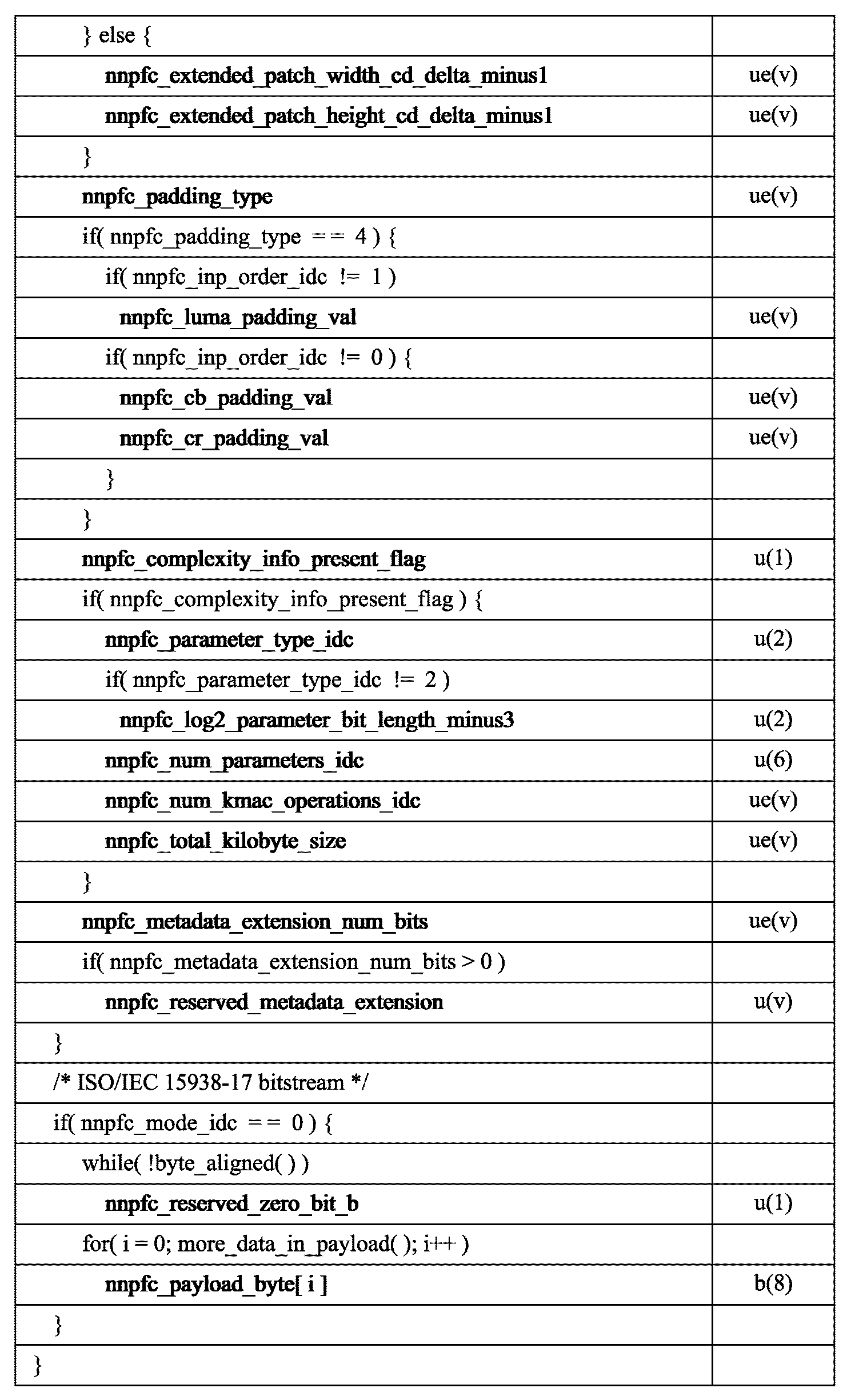
  • the NNPFC syntax structures of Tables 1 to 3 can be signaled in the form of a supplemental enhancement information (SEI) message.
  • SEI Supplemental Enhancement Information
  • An SEI message signaling the NNPFC syntax structures of Tables 1 to 3 can be referred to as an NNPFC SEI message.
  • the NNPFC SEI message can specify a neural network that can be used as a post-processing filter.
  • the use of specific post-processing filters (NNPFs) for specific pictures can be indicated using neural-network post-filter activation SEI messages.
  • 'post-processing filter' and 'post filter' can have the same meaning.
  • SEI messages may require defining the following variables:
  • the input picture width and height in luma sample units can be represented as CroppedWidth and CroppedHeight, respectively.
  • CroppedYPic[idx] an array of luma samples of input pictures with indices idx in the range of 0 to numInputPics-1
  • CroppedCbPic[idx] and CroppedCrPic[idx] which are arrays of chroma samples, can be used as inputs to NNPF if they exist.
  • BitDepth Y can represent the bit depth of the luma sample array of input pictures.
  • BitDepth C can represent the bit depth of the chroma sample arrays (if any) of the input pictures.
  • ChromaFormatIdc can represent a chroma format identifier.
  • the filtering strength control value array StrengthControlVal[idx] must contain real numbers in the range 0 to 1 for input pictures with indices idx in the range 0 to numInputPics-1.
  • An input picture having index 0 may correspond to a picture for which an NNPF defined by the NNPFC SEI message is activated by the NNPFA SEI message.
  • An input picture having index i in the range of 0 to numInputPics-1 may precede an input picture having index i-1 in the output order.
  • the variables SubWidthC and SubHeightC can be derived from ChromaFormatIdc. More than one NNPFC SEI message can exist for the same picture. If more than one NNPFC SEI message with different nnpfc_id values exists or is enabled for the same picture, the two or more NNPFC SEI messages can have the same or different nnpfc_purpose and nnpfc_mode_idx values.
  • nnpfc_purpose can represent the purpose of NNPF as specified in Table 3.
  • (nnpfc_purpose & bitMask) being non-zero can represent that NNPF has a purpose associated with the bitMask value in Table 3. If nnpfc_purpose is greater than 0 and (nnpfc_purpose & bitMask) is 0, the purpose associated with the bitMask value may not be applied to NNPF. If nnpfc_pupose is 0, NNPF can be used.
  • nnpfc_purpose value must be in the range 0 to 63 inclusive in the bitstream.
  • the values 64 to 65535 for nnpfc_purpose are reserved for future use and may not be present in the bitstream. Decoders must ignore NNPFC SEI messages containing npfc_purpose in the range 64 to 65535.
  • chromaUpsamplingFlag chromaUpsamplingFlag, resolutionResamplingFlag, pictureRateUpsamplingFlag, bitDepthUpsamplingFlag, and colourizationFlag, which specify whether nnpfc_purpose indicates the purpose of NNPF, which includes chroma upsampling, resolution resamplingFlag, pictureRateUpsamplingFlag, bitDepthUpsamplingFlag, and colourizationFlag, can be derived as shown in Table 5 below.
  • the syntax of the above SEI message may be extended with a syntax element whose presence is determined by nnpfc_purpose matching that value.
  • ChromaFormatIdc is 3, chromaUpsamplingFlag must be equal to 0.
  • colourizationFlag If ChromaFormatIdc or chromaUpsamplingFlag is non-zero, colourizationFlag must be equal to 0.
  • pictureRateUpsamplingFlag is 1 and the input picture with index 0 is associated with a frame packing arrangement SEI message having fp_arrangement_type equal to 5, then all input pictures may be associated with a frame packing arrangement SEI message having fp_arrangement_type equal to 5 and fp_current_frame_is_frame0_flag of the same value.
  • nnpfc_id may contain an identification number that can be used to identify a postprocessing filter.
  • the nnpfc_id value must be in the range of 0 to 2 32 - 2, inclusive.
  • the nnpfc_id values in the range of 256 to 511 and in the range of 2 31 to 2 32 - 2 may be reserved for future use. Decoders should ignore NNPFC SEI messages with nnpfc_id in the range of 256 to 511 or in the range of 2 31 to 2 32 - 2.
  • NNPFC SEI message is the first NNPFC SEI message in decoding order with a particular nnpfc_id value within the current Coded Layer Video Sequence (CLVS), the following may apply:
  • the above SEI message may represent a base post-processing filter (NNPF).
  • the above SEI message can be associated with the current decoded picture and all subsequent decoded pictures of the current layer until the end of the current CLVS, in output order.
  • a value of nnpfc_base_flag of 1 can indicate that the SEI message specifies the base NNPF.
  • a value of nnpfc_base_flag of 0 can indicate that the SEI message specifies an update related to the base NNPF.
  • nnpfc_base_flag value The following constraints may apply to the nnpfc_base_flag value:
  • the nnpfc_base_flag value must be equal to 1.
  • NNPFC SEI message nnpfcB is not the first NNPFC SEI message in decoding order with a particular nnpfc_id value within the current CLVS and has nnpfc_base_flag equal to 1, then the NNPFC SEI message shall be a repetition of the first NNPFC SEI message nnpfcA with the same nnpfc_id value in decoding order. That is, the payload content of nnpfcB shall be identical to the payload content of nnpfcA.
  • nnpfc_base_flag 0
  • the above SEI message may define updates relative to a base NNPF preceding in decoding order with the same nnpfc_id value.
  • the updates are not cumulative, but rather each update may be applied to the base NNPF, which is the NNPF specified by the first NNPFC SEI message in decoding order with a particular nnpfc_id value within the current CLVS.
  • the NNPF defined by the above SEI message may be obtained by applying the updates defined by the above SEI message relative to a base NNPF with the same nnpfc_id value.
  • the above SEI message is associated with the current decoded picture and all subsequent decoded pictures of the current layer in decoding order until the current CLVS ends or until the decoded picture following the current decoded picture in output order within the current CLVS is excluded, and may be associated with subsequent NNPFC SEI messages in decoding order that have nnpfc_base_flag equal to 0 and have a specific nnpfc_id value earlier in the current CLVS.
  • a value of nnpfc_mode_idc of 0 may indicate that the SEI message contains a bitstream compliant with ISO/IEC 15938-17 that specifies a base NNPF (if nnpfc_base_flag is 1) or is an update associated with a base NNPF with the same nnpfc_id value (if nnpfc_base_flag is 0).
  • nnpfc_mode_idc When nnpfc_mode_idc is 1, a value of nnpfc_mode_idc 1 may indicate that the underlying NNPF associated with the nnpfc_id value is a neural network, and the neural network may be a neural network identified by a URI denoted as nnpfc_uri using a format identified by a tag URI nnpfc_tag_uri.
  • nnpfc_mode_idc When nnpfc_mode_idc is 0, a value of nnpfc_mode_idc 1 may indicate that an update to the underlying NNPF with the same nnpfc_id value is defined by a URI denoted as nnpfc_uri using a format identified by a tag URI nnpfc_tag_uri.
  • nnpfc_mode_idc The value of nnpfc_mode_idc must be in the range 0 to 1 in the bitstream. Values in the range 2 to 255 for nnpfc_mode_idc are reserved for future use and may not be present in the bitstream. Decoders must ignore NNPFC SEI messages with nnpfc_mode_idc in the range 2 to 255. Values of nnpfc_mode_idc greater than 255 are not present in the bitstream and may not be reserved for future use.
  • nnpfc_reserved_zero_bit_a must be equal to 0 in the bitstream. Decoders must ignore NNPFC SEI messages with a non-zero value of nnpfc_reserved_zero_bit_a.
  • nnpfc_tag_uri may contain a tag URI with syntax and semantics specified in IETF RFC 4151 that identifies the format and relevant information for an update with respect to the neural network used as the primary NNPF or a primary NNPF having the same nnpfc_id value specified by nnpfc_uri.
  • nnpfc_tag_uri can uniquely identify the format of neural network data specified by nnrpf_uri without the need for a central registration authority.
  • nnpfc_tag_uri may indicate that the neural network data identified by the nnpfc_uri is compliant with ISO/IEC 15938-17.
  • nnpfc_uri MAY contain a URI with syntax and semantics specified in IETF Internet Standard 66 that identifies a neural network that is used as the primary NNPF, or an update to the primary NNPF with the same nnpfc_id value.
  • a value of 1 for nnpfc_formatting_and_purpose_flag may indicate the presence of syntax elements related to filter purpose, input formatting, output formatting, and complexity.
  • a value of 0 for nnpfc_formatting_and_purpose_flag may indicate the absence of syntax elements related to filter purpose, input formatting, output formatting, and complexity.
  • nnpfc_base_flag 1
  • nnpfc_property_present_flag 1
  • nnpfc_property_present_flag When nnpfc_property_present_flag is 0, the values of all syntax elements that can only be present when nnpfc_property_present_flag is 1 can be inferred to be identical to their corresponding syntax elements in the NNPFC SEI message containing the base NNPF to which the above SEI message provides updates.
  • the NNPFC SEI message nnpfcCurr is not the first NNPFC SEI message in decoding order with a particular nnpfc_id value within the current CLVS, is not a repeat of the first NNPFC SEI message with the particular nnpfc_id value (i.e., has nnpfc_base_flag equal to 0), and has nnpfc_property_present_flag equal to 1.
  • nnpfc_purpose value of a NNPFC SEI message must be identical to the nnpfc_purpose value of the first NNPFC SEI message in decoding order that has a specific nnpfc_id value within the current CLVS.
  • nnpfc_complexity_info_present_flag 0 or both nnpfc_complexity_info_present_flag shall be equal to 1, and all of the following may apply:
  • nnpfc_parameter_type_idc of nnpfcCurr must be the same as nnpfc_parameter_type_idc of nnpfcBase.
  • nnpfc_log2_parameter_bit_length_minus3 of nnpfcCurr must be less than or equal to nnpfc_log2_parameter_bit_length_minus3 of nnpfcBase, if present.
  • nnpfc_num_parameters_idc of nnpfcBase is greater than 0
  • nnpfc_num_parameters_idc of nnpfcCurr must be greater than 0 and less than or equal to nnpfc_num_parameters_idc of nnpfcBase.
  • nnpfc_num_kmac_operations_idc of nnpfcBase 0 if npfc_num_kmac_operations_idc of nnpfcBase is 0, nnpfc_num_kmac_operations_idc of nnpfcCurr must be equal to 0.
  • nnpfc_num_kmac_operations_idc in nnpfcBase is greater than 0
  • nnpfc_num_kmac_operations_idc in nnpfcCurr must be greater than 0 and less than or equal to nnpfc_num_kmac_operations_idc in nnpfcBase.
  • nnpfc_total_kilobyte_size of nnpfcBase is 0, nnpfc_total_kilobyte_size of nnpfcCurr must be equal to 0.
  • nnpfc_total_kilobyte_size of nnpfcBase is greater than 0
  • nnpfc_total_kilobyte_size of nnpfcCurr must be greater than 0 and less than or equal to nnpfc_total_kilobyte_size of nnpfcBase.
  • nnpfc_num_input_pics_minus1 +_1 can represent the number of pictures used as input to NNPF.
  • the value of nnpfc_num_input_pics_minus1 must be in the range of 0 to 63. If pictureRateUpsamplingFlag is equal to 1, the value of nnpfc_num_input_pics_minus1 must be greater than 0.
  • variable numInputPics which represents the number of pictures used as input to NNPF, can be derived as shown in the following Equation 1.
  • a value of 1 of nnpfc_input_pic_output_flag[i] may indicate that NNPF generates the corresponding output picture for the i-th input picture.
  • a value of 0 of nnpfc_input_pic_output_flag[i] may indicate that NNPF does not generate the corresponding output picture for the i-th input picture. If nnpfc_num_input_pics_minus1 is equal to 0, nnpfc_input_pic_output_flag[0] may be inferred to be 1.
  • nnpfc_num_input_pics_minus1 is greater than 0
  • nnpfc_input_pic_output_flag[i] shall be equal to 1 for at least one value of i in the range of 0 to nnpfc_num_input_pics_minus1.
  • a value of nnpfc_absent_input_pic_zero_flag of 1 may indicate that NNPF expects an input picture that is not present in the bitstream to be represented by sample arrays with sample values of 0.
  • a value of nnpfc_absent_input_pic_zero_flag of 0 may indicate that NNPF expects an input picture that is not present in the bitstream to be represented by the closest input picture in output order in the bitstream.
  • nnpfc_out_sub_c_flag may indicate the values of variables outSubWidthC and outSubHeightC when chromaUpsamplingFlag is 1.
  • a value of nnpfc_out_sub_c_flag of 1 may indicate that the value of outSubWidthC is 1 and the value of outSubHeightC is 1.
  • a value of nnpfc_out_sub_c_flag of 0 can indicate that the value of outSubWidthC is 2 and the value of outSubHeightC is 1. If the value of ChromaFormatIdc is 2 and nnpfc_out_sub_c_flag is present, the value of nnpfc_out_sub_c_flag must be equal to 1.
  • nnpfc_out_colour_format_idc can indicate the colour format of NNPF and consequently the values of variables outSubWidthC and outSubHeightC when colourizationFlag is 1.
  • a value of nnpfc_out_colour_format_idc of 1 can indicate that the colour format of NNPF output is 4:2:0, and both outSubWidthC and outSubHeightC are 2.
  • a value of nnpfc_out_colour_format_idc of 2 can indicate that the colour format of NNPF output is 4:2:2, outSubWidthC is 2, and outSubHeightC is 1.
  • nnpfc_out_colour_format_idc of 3 can indicate that the colour format of NNPF output is 4:4:4, and both outSubWidthC and outSubHeightC are 1.
  • the value of nnpfc_out_colour_format_idc must not be 0.
  • nnpfc_pic_width_num_minus1 + 1 and nnpfc_pic_width_denom_minus1 + 1 can represent the numerator and denominator respectively for the resampling ratio of the NNPF output picture width with respect to CroppedWidth.
  • the value of (nnpfc_pic_width_num_minus1 +1) ⁇ (nnpfc_pic_width_denom_minus1 +1) must be in the range of 1 ⁇ 16 to 16.
  • nnpfc_pic_width_num_minus1 and nnpfc_pic_width_denom_minus1 do not exist, the values of nnpfc_pic_width_num_minus1 and nnpfc_pic_width_denom_minus1 can be inferred to be both equal to 0.
  • nnpfcOutputPicWidth which represents the width of the luma sample arrays of the picture(s) resulting from applying the NNPF identified by nnpfc_id to the input picture(s), can be derived as shown in Equation 2 below.
  • nnpfcOutputPicWidth % outSubWidthC It is a bitstream conformance requirement that the value of nnpfcOutputPicWidth % outSubWidthC must be equal to 0.
  • nnpfc_pic_height_num_minus1 + 1 and nnpfc_pic_height_denom_minus1 + 1 may represent the numerator and denominator, respectively, for the resampling ratio of the NNPF output picture height with respect to CroppedHeight.
  • the value of (nnpfc_pic_height_num_minus1 + 1) ⁇ (nnpfc_pic_height_denom_minus1 + 1) shall be in the range of 1 ⁇ 16 to 16, inclusive.
  • nnpfc_pic_height_num_minus1 and nnpfc_pic_height_denom_minus1 do not exist, the values of nnpfc_pic_height_num_minus1 and nnpfc_pic_height_denom_minus1 can be inferred to be both equal to 0.
  • nnpfcOutputPicHeight which represents the height of the luma sample arrays of the picture(s) resulting from applying the NNPF identified by nnpfc_id to the input picture(s), can be derived as shown in the following Equation 3.
  • nnpfcOutputPicHeight % outSubHeightC It is a bitstream conformance requirement that the value of nnpfcOutputPicHeight % outSubHeightC must be equal to 0.
  • nnpfc_pic_width_num_minus1, nnpfc_pic_width_denom_minus1, nnpfc_pic_height_num_minus1, and nnpfc_pic_height_denom_minus1 exist, at least one of the following must be true:
  • nnpfcOutputPicWidth is not equal to CroppedWidth.
  • nnpfcOutputPicHeight is not equal to CroppedHeight.
  • nnpfc_interpolated_pics[i] can represent the number of interpolated pictures generated by NNPF between the i-th picture used as input to NNPF and the (i + 1)-th picture.
  • nnpfc_interpolated_pics[i] must be in the range of 0 to 63, inclusive.
  • the value of nnpfc_interpolated_pics[i] must be greater than 0 for at least one value of i in the range of 0 to nnpfc_num_input_pics_minus1 - 1.
  • NumInpPicsInOutputTensor representing the number of pictures existing in the output tensor of NNPF with the corresponding input picture
  • InpIdx[idx] representing the input picture index of the idxth picture existing in the output tensor of NNPF with the corresponding input picture
  • numOutputPics representing the total number of pictures existing in the output tensor of NNPF
  • nnpfc_component_last_flag can indicate that the last dimension of the input tensor inputTensor for NNPF and the output tensor outputTensor which is the result of NNPF are used for the current channel.
  • the value 0 of nnpfc_component_last_flag can indicate that the third dimension of the input tensor inputTensor for NNPF and the output tensor outputTensor which is the result of NNPF are used for the current channel.
  • the first dimension of the input and output tensors can be used as batch indices used in some neural network frameworks.
  • the semantics of this SEI message use the batch size corresponding to the batch index equal to 0, but the batch size used as input to neural network inference can be determined by the implementation of postprocessing.
  • the input tensor can have 7 channels, including 4 luma matrices, 2 chroma matrices, and 1 auxiliary input matrix.
  • the DeriveInputTensors() process can derive each of the 7 channels of the input tensor one by one, and when a particular channel among these channels is processed, that channel can be referred to as the current channel during the process.
  • nnpfc_inp_format_idc can indicate how to convert the sample values of the input picture to the input values of NNPF. If nnpfc_inp_format_idc is 0, the input values to NNPF are real numbers, and the functions InpY() and InpC() can be specified as shown in the following Equation 4.
  • nnpfc_inp_format_idc the input values of NNPF are unsigned integer numbers, and the functions InpY() and InpC() can be derived as shown in Table 7.
  • variable inpTensorBitDepth y can be derived from the syntax element nnpfc_inp_tensor_bitlength_minus8 described below.
  • inpTensorBitDepth C can be derived from the syntax element nnpfc_inp_tensor_chroma_bitdepth_minus8 described below.
  • nnpfc_inp_format_idc Values of nnpfc_inp_format_idc greater than 1 are reserved for future use and may not be present in the bitstream. Decoders must ignore NNPFC SEI messages containing reserved values of nnpfc_inp_format_idc.
  • a value of nnpfc_auxiliary_inp_idc greater than 0 may indicate that auxiliary input data exists in the input tensor of NNPF.
  • a value of nnpfc_auxiliary_inp_idc of 0 may indicate that auxiliary input data does not exist in the input tensor.
  • a value of nnpfc_auxiliary_inp_idc of 1 may indicate that auxiliary input data is derived as described in Equation 5 below.
  • nnpfc_auxiliary_inp_idc The value of nnpfc_auxiliary_inp_idc must be in the range 0 to 1 in the bitstream. Values of nnpfc_auxiliary_inp_idc in the range 2 to 255 are reserved for future use and may not be present in the bitstream. Decoders must ignore NNPFC SEI messages containing nnpfc_auxiliary_inp_idc in the range 2 to 255. Values of nnpfc_auxiliary_inp_idc greater than 255 are not present in the bitstream and are not reserved for future use.
  • nnpfc_inp_order_idc can indicate how to order the sample array of input pictures to form an input tensor for NNPF.
  • nnpfc_inp_order_idc The value of nnpfc_inp_order_idc must be in the range 0 to 3 in the bitstream. Values of 4 to 255 for nnpfc_inp_order_idc are reserved for future use and may not be present in the bitstream. Decoders must ignore NNPFC SEI messages with nnpfc_inp_order_idc in the range 4 to 255. Values of nnpfc_inp_order_idc greater than 255 are not present in the bitstream and are not reserved for future use.
  • nnpfc_inp_order_idc must not be 3.
  • nnpfc_inp_order_idc must be equal to 0.
  • nnpfc_inp_order_idc must not be 0 if chromaUpsamplingFlag is 1.
  • Table 8 contains a description of the nnpfc_inp_order_idc values.
  • nnpfc_inp_tensor_bitlength_minus8 + 8 can represent the bit depth of luma sample values in the input integer tensor.
  • the value of inpTensorBitDepth Y can be derived as shown in Equation 5.
  • nnpfc_inp_tensor_luma_bitdepth_minus8 It is a bitstream conformance requirement that the value of nnpfc_inp_tensor_luma_bitdepth_minus8 must be in the range of 0 to 24.
  • nnpfc_inp_tensor_chroma_bitdepth_minus8 + 8 can represent the bit depth of chroma sample values in the input integer tensor.
  • the value of inpTensorBitDepth C can be derived as in Equation 6.
  • nnpfc_inp_tensor_chroma_bitdepth_minus8 It is a bitstream conformance requirement that the value of nnpfc_inp_tensor_chroma_bitdepth_minus8 must be in the range of 0 to 24.
  • variable strengthControlScaledVal can be derived as shown in Table 9 below.
  • a patch may be a rectangular array of samples from a component of a picture (e.g., a luma or chroma component).
  • the process DeriveInputTensors( ) to derive an input tensor inputTensor for given vertical sample coordinates cTop and horizontal sample coordinates cLeft specifying the upper-left sample location for a patch of samples contained in the input tensor can be represented as a combination of Tables 10 to 12.
  • a value of nnpfc_out_format_id of 0 may indicate that the sample values output to the NNPF are real numbers that map linearly to an unsigned integer value range of 0 to (1 ⁇ bitDepth) - 1 for the desired bit depth bitDepth for subsequent post-processing or display, where the real numbers may be in the value range of 0 to 1.
  • a value of nnpfc_out_format_flag of 1 can indicate that the luma sample values output by NNPF are unsigned integers in the range of 0 to (1 ⁇ outTensorBitDepth Y ) - 1, and that the chroma sample values output by NNPF are unsigned integers in the range of (1 ⁇ outTensorBitDepth C ) - 1.
  • nnpfc_out_format_idc Values of nnpfc_out_format_idc greater than 1 may be reserved for future specifications and are not present in the bitstream. Decoders must ignore NNPFC SEI messages containing reserved values of nnpfc_out_format_idc.
  • nnpfc_out_order_idc can indicate the output order of samples due to NNPF.
  • nnpfc_out_order_idc The value of nnpfc_out_order_idc must be in the range 0 to 3 in the bitstream. Values of 4 to 255 for nnpfc_out_order_idc are reserved for future use and may not be present in the bitstream. Decoders must ignore NNPFC SEI messages containing nnpfc_out_order_idc in the range 4 to 255. Values of nnpfc_out_order_idc greater than 255 are not present in the bitstream and are not reserved for future use.
  • chromaUpsamplingFlag is 1, nnpfc_out_order_idc must not be 0 or 3.
  • nnpfc_out_order_idc must not be 0.
  • Table 13 contains a description of the nnpfc_out_order_idc values.
  • nnpfc_out_tensor_luma_bitdepth_minus8 + 8 can represent the bit depth of the luma sample values of the output integer tensor.
  • the value of nnpfc_out_tensor_luma_bitdepth_minus8 must be in the range of 0 to 24.
  • the value of outTensorBitDepth Y can be derived as shown in Equation 7.
  • nnpfc_out_tensor_chroma_bitdepth_minus8 + 8 can represent the bit depth of the chroma sample values of the output integer tensor.
  • the value of nnpfc_out_tensor_chroma_bitdepth_minus8 must be in the range of 0 to 24.
  • the value of outTensorBitDepth C can be derived as shown in Equation 8.
  • bitDepthUpsamplingFlag If bitDepthUpsamplingFlag is 1, the value of nnpfc_out_format_idc must be equal to 1, and at least one of the following conditions must be true:
  • outTensorBitDepth Y is greater than inpTensorBitDepth Y , then outTensorBitDepth C must be less than inpTensorBitDepth C.
  • outTensorBitDepth C is greater than inpTensorBitDepth C , then outTensorBitDepth Y must be less than inpTensorBitDepth Y.
  • the process StoreOutputTensors( ) to derive sample values in the filtered output sample arrays FilteredYPic, FilteredCbPic and FilteredCrPic from the output tensor outputTensor with respect to the given vertical sample coordinates cTop and horizontal sample coordinates cLeft indicating the top-left sample location for the patch of samples contained in the input tensor can be expressed as a combination of Tables 14 and 15.
  • a value of 1 for nnpfc_separate_colour_description_present_flag may indicate that a unique combination of colour primaries, transformation properties, matrix coefficients, and scaling and offset values applied with respect to matrix coefficients for a picture due to NNPF is specified in the SEI message syntax structure.
  • a value of 0 for nnpfc_separate_colour_description_present_flag may indicate that a combination of colour primaries, transformation properties, matrix coefficients, and scaling and offset values applied with respect to matrix coefficients for a picture due to a post-processing filter is the same as indicated in the VUI parameters of CLVS.
  • nnpfc_colour_primaries may have the same semantics as defined for the vui_colour_primaries syntax element, except that:
  • - nnpfc_colour_primaries can represent the primary colors of a picture that result from applying NNPF specified in the SEI message, rather than the primary colors used in CLVS.
  • nnpfc_colour_primaries does not exist in the NNPFC SEI message, the value of nnpfc_colour_primaries can be inferred to be equal to the value of vui_colour_primaries.
  • nnpfc_transfer_characteristics can have the same semantics as defined for the vui_transfer_characteristics syntax element, except that:
  • - nnpfc_transfer_characteristics can indicate the transfer characteristics of a picture that results from applying NNPF specified in the SEI message, rather than the transfer characteristics used in CLVS.
  • nnpfc_transfer_characteristics If nnpfc_transfer_characteristics does not exist in the NNPFC SEI message, the value of nnpfc_transfer_characteristics can be inferred to be the same as the value of vui_transfer_characteristics.
  • nnpfc_matrix_coeffs can describe the formulas used to derive luma and chroma signals from the green, blue, red or Y, Z, X primaries. Its semantics apply to the picture resulting from applying the NNPF specified in the SEI message above, and can be the same as those specified for MatrixCoefficients, which include outTensorBitDepth C and BitDepth C , which are equal to outTensorBitDepth Y and outTensorBitDepth C , respectively.
  • nnpfc_matrix_coeffs does not exist in the NNPFC SEI message, the value of nnpfc_matrix_coeffs can be inferred to be equal to the value of vui_matrix_coeffs.
  • nnpfc_matrix_coeffs cannot be equal to 0 unless all of the following conditions are true:
  • nnpfc_out_tensor_chroma_bitdepth_minus8 is equivalent to nnpfc_out_tensor_luma_bitdepth_minus8.
  • outSubHeightC is equal to 1
  • outSubWidthC is equal to 1.
  • nnpfc_matrix_coeffs cannot be equal to 8 unless one of the following conditions is true:
  • nnpfc_out_tensor_chroma_bitdepth_minus8 is equivalent to nnpfc_out_tensor_luma_bitdepth_minus8.
  • nnpfc_out_tensor_chroma_bitdepth_minus8 is equal to nnpfc_out_tensor_luma_bitdepth_minus8 + 1
  • nnpfc_out_order_idc is equal to 2
  • outSubHeightC is equal to 1
  • outSubWidthC is equal to 1.
  • nnpfc_full_range_flag can indicate scaling and offset values applied with respect to matrix coefficients as specified by nnpfc_matrix_coeffs. Its semantics can be identical to those specified for the VideoFullRangeFlag parameter. If it is not present, the value of nnpfc_full_range_flag can be inferred to be equal to 0.
  • a value of nnpfc_chroma_loc_info_present_flag of 1 may indicate the presence of the nnpfc_chroma_sample_loc_type_frame syntax element of the NNPFC SEI message.
  • a value of nnpfc_chroma_loc_info_present_flag of 0 may indicate the absence of the nnpfc_chroma_sample_loc_type_frame syntax element of the NNPFC SEI message.
  • the value of nnpfc_chroma_loc_info_present_flag shall be equal to 0 if colourizationFlag is 0 or nnpfc_out_colour_format_idc is not 1.
  • nnpfc_chroma_sample_loc_type_frame may indicate the locations of chroma samples of output pictures, if nnpfc_chroma_sample_loc_type_frame is not 6 and nnpfc_out_colour_format_idc is equal to 1. If nnpfc_chroma_sample_loc_type_frame is 6 and nnpfc_out_colour_format_idc is equal to 1, it may indicate that the locations of chroma samples are unknown, unspecified, or specified by other means.
  • the value of nnpfc_chroma_sample_loc_type_frame must be in the range 0 to 6, inclusive.
  • nnpfc_overlap can indicate the number of overlapping horizontal and vertical samples of adjacent input tensors of NNPF.
  • the value of nnpfc_overlap must be in the range of 0 to 16383, inclusive.
  • a value of nnpfc_constant_patch_size_flag of 1 can indicate that NNPF accepts as input exactly the patch sizes indicated by nnpfc_patch_width_minus1 and nnpfc_patch_height_minus1.
  • a value of nnpfc_constant_patch_size_flag of 0 can indicate that NNPF accepts as input any patch size with width inpPatchWidth and height inpPatchHeight.
  • npfc_patch_width_minus1 + 1 can represent the number of horizontal samples of the patch size required for the input of NNPF when the value of nnpfc_constant_patch_size_flag is 1.
  • the value of nnpfc_patch_width_minus1 must be in the range of 0 to Min(32766, CroppedWidth - 1).
  • npfc_patch_height_minus1 + 1 can represent the number of vertical samples of the patch size required for the input of NNPF when the value of nnpfc_constant_patch_size_flag is 1.
  • the value of nnpfc_patch_height_minus1 must be in the range of 0 to Min(32766, CroppedHeight - 1).
  • nnpfc_extended_patch_width_cd_delta_minus1 + 1 + 2 * nnpfc_overlap may represent the common divisor of all allowed values of extended patch widths required for input to NNPF when nnpfc_constant_patch_size_flag is 0.
  • the value of nnpfc_extended_patch_width_cd_delta_minus1 must be in the range 0 to Min(32766, CroppedWidth - 1).
  • nnpfc_extended_patch_height_cd_delta_minus1 + 1 + 2 * nnpfc_overlap may represent the common divisor of all allowed values of extended patch heights required for input to NNPF when nnpfc_constant_patch_size_flag is 0.
  • the value of nnpfc_extended_patch_height_cd_delta_minus1 must be in the range 0 to Min(32766, CroppedHeight - 1).
  • inpPatchWidth and inpPatchHeight can be set to the patch size width and patch size height respectively.
  • nnpfc_constant_patch_size_flag 0
  • inpPatchWidth and inpPatchHeight can be provided by external means or set by the post-processor itself.
  • inpPatchWidth + 2 * nnpfc_overlap must be a positive integer multiple ofnnpfc_extended_patch_width_cd_delta_minus1 + 1 + 2 * nnpfc_overlap , and inpPatchWidth must be less than or equal to CroppedWidth.
  • the value of inpPatchHeight + 2 * nnpfc_overlap must be a positive integer multiple ofnnpfc_extended_patch_height_cd_delta_minus1 + 1 + 2 * nnpfc_overlap , and inpPatchHeight must be less than or equal to CroppedHeight.
  • the value of inpPatchWidth may be set equal to nnpfc_patch_width_minus1 + 1
  • the value of inpPatchHeight may be set equal to nnpfc_patch_height_minus1 + 1.
  • outPatchWidth, outPatchHeight, horCScaling, verCScaling, outPatchCWidth, outPatchCHeight, and overlapSize can be derived as shown in Table 16.
  • outPatchWidth * CroppedWidth must equal nnpfc_pic_width_in_luma_samples * inpPatchWidth
  • outPatchHeight * CroppedHeight must equal nnpfc_pic_height_in_luma_samples * inpPatchHeight.
  • nnpfc_padding_type can indicate the padding process when referencing sample positions that are outside the boundary of the input picture, as described in Table 17.
  • the values of nnpfc_padding_type must be in the range 0 to 4 in the bitstream.
  • the values 5 to 15 for nnpfc_padding_type are reserved for future use and may not be present in the bitstream. Decoders should ignore NNPFC SEI messages containing nnpfc_padding_type in the range 5 to 15.
  • the values of nnpfc_padding_type greater than 15 are not present in the bitstream and are not reserved for future use.
  • nnpfc_luma_padding_val can indicate the luma value to use for padding when the value of nnpfc_padding_type is 4.
  • the value of nnpfc_luma_padding_val must be in the range of 0 to (1 ⁇ BitDepth Y ) - 1.
  • nnpfc_cb_padding_val can indicate the Cb value to be used for padding when the value of nnpfc_padding_type is 4.
  • the value of nnpfc_cb_padding_val must be in the range of 0 to (1 ⁇ BitDepth C ) - 1.
  • nnpfc_cr_padding_val can indicate the Cr value to be used for padding when the value of nnpfc_padding_type is 4.
  • the value of nnpfc_cr_padding_val must be in the range of 0 to (1 ⁇ BitDepthC) - 1.
  • sampleVal (y, x, picHeight, picWidth, CroppedPic) with inputs vertical sample position y, horizontal sample position x, picture height picHeight, picture width picWidth, sample array CroppedPic, and component index cIdx (equal to 0 for luma, 1 for Cb, and 2 for Cr) can return a value of SampleVal derived as shown in Table 18.
  • NNPF PostProcessingFilter( ) may be a target NNPF derived from the semantics of the NNPFA SEI message.
  • the following example process may be used to generate filtered and/or interpolated picture(s) in a patch-wise manner.
  • the filtered and/or interpolated picture(s) may include a Y sample array FilteredYPic, a Cb sample array FilteredCbPic and a Cr sample array FilteredCrPic as specified by nnpfc_out_order_idc.
  • An NNPF-generated picture containing index i may contain sample arrays FilteredYPic[i], FilteredCbPic[i], and FilteredCrPic[i] derived by Table 19, if any.
  • An NNPF-generated picture may not contain overlapping regions.
  • the NNPF process can output NNPF-generated pictures in their increasing index order, forming a process defined by Table 19.
  • all NNPF-generated pictures interpolated by the NNPF are output, and NNPF-generated pictures corresponding to all input pictures to the NNPF can be output as specified in the semantics of the NNPFA SEI message.
  • a value of 1 for nnpfc_complexity_info_present_flag may indicate the presence of one or more syntax elements indicating the complexity of the NNPF associated with the nnpfc_id.
  • a value of 0 for nnpfc_complexity_info_present_flag may indicate that no syntax elements indicating the complexity of the NNPF associated with the nnpfc_id are present.
  • a value of nnpfc_parameter_type_idc of 0 can indicate that the network uses only integer parameters.
  • a value of nnpfc_parameter_type_flag of 1 can indicate that the network can use either floating-point or integer parameters.
  • a value of nnpfc_parameter_type_idc of 2 can indicate that the network uses only binary parameters.
  • a value of nnpfc_parameter_type_idc of 3 is reserved for future use and is not present in the bitstream. Decoders should ignore NNPFC SEI messages with a value of nnpfc_parameter_type_idc of 3.
  • nnpfc_log2_parameter_bit_length_minus3 can indicate that the neural network does not use parameters with bit length greater than 8, 16, 32, and 64, respectively. If nnpfc_parameter_type_idc exists and nnpfc_log2_parameter_bit_length_minus3 does not exist, the neural network may not use parameters with bit length greater than 1.
  • nnpfc_num_parameters_idc can represent the maximum number of neural network parameters for NNPF in powers of 2048.
  • a value of nnpfc_num_parameters_idc of 0 can indicate that the maximum number of neural network parameters is unknown.
  • the value of nnpfc_num_parameters_idc must be in the range of 0 to 52. Values of nnpfc_num_parameters_idc greater than 52 are reserved for future use and must not be present in the bitstream. Decoders should ignore NNPFC SEI messages with nnpfc_num_parameters_idc greater than 52.
  • nnpfc_num_parameters_idc If the value of nnpfc_num_parameters_idc is greater than 0, the variable maxNumParameters can be derived as in Equation 9.
  • a value of nnpfc_num_kmac_operations_idc greater than 0 may indicate that the maximum number of multiply-accumulate operations per sample in NNPF is less than or equal to nnpfc_num_kmac_operations_idc * 1000.
  • a value of nnpfc_num_kmac_operations_idc of 0 may indicate that the maximum number of multiply-accumulate operations in the network is unknown.
  • the value of nnpfc_num_kmac_operations_idc must be in the range of 0 to 232 - 2, inclusive.
  • a value of nnpfc_total_kilobyte_size greater than 0 can indicate the total size (in kilobytes) required to store the uncompressed parameters of the neural network.
  • the total size in bits can be a number greater than or equal to the sum of the bits used to store each parameter.
  • nnpfc_total_kilobyte_size can be the total size (in bits) divided by 8000, rounded up.
  • a value of nnpfc_total_kilobyte_size of 0 can indicate that the total size required to store the parameters for the neural network is not known.
  • the value of nnpfc_total_kilobyte_size must be in the range 0 to 2 32 - 2, inclusive.
  • a value of nnpfc_metadata_extension_num_bits of 0 can indicate that no nnpfc_reserved_metadata_extension exists.
  • a value of nnpfc_metadata_extension_num_bits greater than 0 can indicate the length of the nnpfc_reserved_metadata_extension in bits.
  • nnpfc_metadata_extension_num_bits must be equal to 0. Values in the range 1 to 2048 for nnpfc_metadata_extension_num_bits are reserved for future use and may not be present in the bitstream.
  • Decoders should accept all values of nnpfc_metadata_extension_num_bits in the range 0 to 2048, inclusive. Values of nnpfc_metadata_extension_num_bits greater than 2048 are not present in the bitstream and are not reserved for future use.
  • nnpfc_reserved_metadata_extension is not present in the bitstream. However, decoders MUST ignore the presence and values of nnpfc_reserved_metadata_extension. If present, the length in bits of nnpfc_reserved_metadata_extension can be equal to nnpfc_metadata_extension_num_bits.
  • nnpfc_reserved_zero_bit_b must be equal to 0 in the bitstream. Decoders must ignore NNPFC SEI messages where nnpfc_reserved_zero_bit_b is not 0.
  • nnpfc_payload_byte[i] may contain the i-th byte of the bitstream.
  • the byte sequence nnpfc_payload_byte[i] for all existing values of i must be a complete bitstream conforming to ISO/IEC 15938-17.
  • the syntax structure for NNPFA is shown in Table 20.
  • the NNPFA syntax structure of Table 20 can be signaled in the form of an SEI message.
  • An SEI message signaling the NNPFA syntax structure of Table 20 may be referred to as an NNPFA SEI message.
  • the NNPFA SEI message can enable or disable the possible use of a target neural network postprocessing filter identified by nnpfa_target_id and nnpfc_base_flag for postprocessing filtering of a picture set.
  • the target NNPF can be derived as follows:
  • nnpfa_target_base_flag 1
  • the target NNPF is the base NNPF with nnpfc_id equal to nnpfa_target_id.
  • the target NNPF is the NNPF specified by the last NNPFC SEI message with an nnpfc_id equal to nnpfa_target_id that precedes the first VCL NAL unit of the current picture in decoding order and is not a repeat of the NNPFC SEI message containing the base NNPF.
  • NNPFA SEI messages may exist for the same picture, if postprocessing filters are used for different purposes or filter different color components.
  • nnpfa_target_id may indicate a target NNPF associated with the current picture and specified by one or more NNPFC SEI messages having an nnpfc_id equal to nnpfa_target_id.
  • nnpfa_target_id The value of nnpfa_target_id must be in the range 0 to 2 - 2, inclusive. nnpfa_target_id values in the range 256 to 511 and in the range 2 - 2 to 2 - 2 may be reserved for future use. Decoders should ignore NNPFA SEI messages with nnpfa_target_id in the range 256 to 511 or 2 - 2 to 2 - 2.
  • NNPFA SEI message with a specific value of nnpfa_target_id must not exist in the current PU (Picture Unit) unless one or both of the following conditions are true:
  • NNPFC SEI message with nnpfc_id equal to a specific value of nnpfa_target_id in the current PU.
  • a PU contains both an NNPFC SEI message with an nnpfc_id of a particular value and an NNPFA SEI message with an nnpfa_target_id equal to the nnpfc_id of a particular value, the NNPFC SEI message shall precede the NNPFA SEI message in decoding order.
  • a value of nnpfa_cancel_flag of 1 may indicate that the persistence of a target neural network post-processing filter set by any previous NNPFA SEI message with the same nnpfa_target_id as the current SEI message is canceled. That is, the target neural network post-processing filter is no longer used unless it is activated by another NNPFA SEI message with the same nnpfa_target_id as the current SEI message and nnpfa_cancel_flag equal to 0.
  • a value of nnpfa_cancel_flag of 0 may indicate that nnpfa_target_base_flag, nnpfa_persistence_flag and nnpfa_num_output_entries follow.
  • a value of nnpfa_target_base_flag of 1 may indicate that the target NNPF is a base NNPF with nnpfc_id equal to nnpfa_target_id.
  • a value of nnpfa_target_base_flag of 0 may indicate that the target NNPF is an NNPF specified by the last NNPFC SEI message with nnpfc_id equal to nnpfa_target_id preceding the first VCL NAL unit of the current picture in decoding order.
  • nnpfa_persistence_flag can indicate the persistence of the target neural network post-processing filter for the current layer.
  • a value of nnpfa_persistence_flag of 0 can indicate that the target neural network post-processing filter can only be used for post-processing filtering for the current picture.
  • a value of nnpfa_persistence_flag of 1 can indicate that the target neural network post-processing filter can be used for post-processing filtering for the current picture and all subsequent pictures in the current layer in output order until one or more of the following conditions are true:
  • the target neural network postprocessing filter is not applied to subsequent pictures within the current layer associated with an NNPFA SEI message that has the same nnpfa_target_id as the current SEI message and an nnpfa_cancel_flag equal to 1.
  • nnpfcTargetPictures be the set of pictures associated with the last NNPFC SEI message that precedes the current NNPFA SEI message in decoding order and has an nnpfc_id equal to nnpfa_target_id.
  • nnpfaTargetPictures be the set of pictures whose target NNPF is activated by the current NNPFA SEI message. It is a bitstream conformance requirement that a picture included in nnpfaTargetPictures must also be included in nnpfcTargetPictures.
  • nnpfa_num_output_entries can indicate the number of nnpfa_output_flag[i] syntax elements present in the NNPFA SEI message.
  • the value of nnpfa_num_output_entries ranges from 0 to NumInpPicsInOutputTensor.
  • a value of 1 in nnpfa_output_flag[i] indicates that the NNPF generated picture corresponding to the input picture with index InpIdx[i] is output by the NNPF process activated by this NNPFA SEI message, where the NNPF process can be specified within the semantics of the NNPFC SEI message.
  • a value of 0 in nnpfa_output_flag[i] can indicate that the NNPF generated picture corresponding to the input picture with index InpIdx[i] is not output by the NNPF process activated by this NNPFA SEI message.
  • nnpfa_num_output_entries is less than NumInpPicsInOutputTensor
  • nnpfa_output_flag[i] can be inferred to be 1 for each value of i in the range from nnpfa_num_output_entries to NumInpPicsInOutputTensor - 1.
  • the post-filter hint syntax structure of Table 21 can be signaled in the form of an SEI message.
  • An SEI message signaling the post-filter hint syntax structure of Table 21 may be referred to as a post-filter hint SEI message.
  • the post-filter hint SEI message can provide post-filter coefficients or correlation information for the design of a post-filter, potentially allowing the decoded and output picture set to be post-processed to achieve improved display quality.
  • a value of 1 for filter_hint_cancel_flag may indicate that the SEI message cancels the persistence of a previous post-filter hint SEI message in the output order applied to the current layer.
  • a value of 0 for filter_hint_cancel_flag may indicate that post-filter hint information follows.
  • filter_hint_persistence_flag may indicate the persistence of the post-filter hint SEI message for the current layer.
  • a value of filter_hint_persistence_flag of 0 may indicate that the post-filter hint applies only to the currently decoded picture.
  • a value of filter_hint_persistence_flag of 1 may indicate that the post-filter hint SEI message applies to the currently decoded picture and persists for all subsequent pictures in the current layer in output order until one or more of the following conditions are true:
  • filter_hint_size_y can indicate the vertical size of the filter coefficients or correlation array.
  • the value of filter_hint_size_y must be in the range of 1 to 15.
  • filter_hint_size_x can indicate the horizontal size of the filter coefficients or correlation array.
  • the value of filter_hint_size_x must be in the range of 1 to 15.
  • filter_hint_type can indicate the type of filter hint transmitted as shown in Table 19.
  • the value of filter_hint_type must be in the range of 0 to 2.
  • a filter_hint_type value equal to 3 must not be present in the bitstream. Decoders must ignore post-filter hint SEI messages with filter_hint_type equal to 3.
  • a value of 1 for filter_hint_chroma_coeff_present_flag can indicate that filter coefficients for chroma exist.
  • a value of 0 for filter_hint_chroma_coeff_present_flag can indicate that filter coefficients for chroma do not exist.
  • filter_hint_value[cIdx][cy][cx] can represent filter coefficients, or cross-correlation matrix elements between the original signal and the decoded signal with 16-bit precision.
  • the value of filter_hint_value[cIdx][cy][cx] must be in the range of -2 31 + 1 to 2 31 - 1.
  • cIdx represents a related color element
  • cy represents a vertical counter
  • cx represents a horizontal counter.
  • the following can be applied.
  • filter_hint_type If the value of filter_hint_type is 0, the coefficients of a two-dimensional FIR (Finite Impulse Response) filter of the size of filter_hint_size_y * filter_hint_size_x can be transmitted.
  • FIR Finite Impulse Response
  • filter_hint_type if the value of filter_hint_type is 1, the filter coefficients of two 1-dimensional FIR filters can be transmitted. In this case, the value of filter_hint_size_y must be 2.
  • An index cy of 0 can represent the filter coefficients of the horizontal filter, and a cy of 1 can represent the filter coefficients of the vertical filter.
  • the horizontal filter In the filtering process, the horizontal filter can be applied first and the result can be filtered by the vertical filter.
  • the transmitted hint may represent the cross-correlation matrix between the original signal s and the decoded signal s'.
  • the normalized cross-correlation matrix for the relevant color components identified by cIdx of the size of filter_hint_size_y * filter_hint_size_x can be defined as in Equation 10.
  • s represents a sample array of the color component cIdx of the original picture
  • s' represents an array of the corresponding decoded picture
  • h represents a vertical height of the corresponding color component
  • w represents a horizontal width of the corresponding color component
  • bitDepth represents a bit depth of the color component.
  • OffsetY is equal to ( filter_hint_size_y >> 1 )
  • OffsetX is equal to ( filter_hint_size_x >> 1 )
  • the decoder can derive a Wiener post-filter from the cross-correlation matrix of the original signal and the decoded signal and the auto-cross-correlation matrix of the decoded signal.
  • an NNPFA SEI message can activate either a base filter (i.e., an NNPFA SEI message with nnpfc_base_flag equal to 1) or an update filter (i.e., an NNPFA SEI message with nnpfc_base_flag equal to 0) based on the value of nnpfa_target_base_flag.
  • a base filter i.e., an NNPFA SEI message with nnpfc_base_flag equal to 1
  • an update filter i.e., an NNPFA SEI message with nnpfc_base_flag equal to 0
  • nnpfa_target_base_flag can only be signaled when nnpfa_cancel_flag has a value of 0. This can cause problems in identifying which NNPF activation should be canceled when there are two NNPF activations with the same nnpfa_target_id but different values of nnpfa_target_base_flag.
  • nnpfa_target_base_flag can be signaled without the condition of nnpfa_cancel_flag value.
  • nnpfa_cancel_flag value is equal to 1
  • the persistence of a previously activated target NNPF with the same values of nnpfa_target_id and nnpfa_target_base_flag can be canceled.
  • NNPFA SEI messages there are no two (or more) NNPFA SEI messages active for the same picture (i.e., containing nnpfa_cancel_flag equal to 0), regardless of the value of nnpfa_target_base_flag.
  • nnpfa_target_base_flag regardless of the value of nnpfa_target_base_flag, two NNPFA SEI messages with the same nnpfa_target_id and nnpfa_cancel_flag set to 0 are not activated.
  • Example 1 provides a description of Summary 1 and Summary 2 described above.
  • the table can be updated as follows.
  • the NNPFA SEI message can enable or disable the possible use of a target NNPF identified by nnpfa_target_id and nnpfa_target_base_flag for post-processing filtering of a set of pictures.
  • the nnpfa_target_base_flag can be parsed without the condition of the nnpfa_cancel_flag value as shown in Table 23. Therefore, for a particular picture for which the NNPF is enabled, the target NNPF can be derived as follows.
  • the target NNPF can be a base NNPF whose nnpfc_id is equal to nnpfa_target_id.
  • the target NNPF is the NNPF specified by the last NNPF SEI message with nnpfc_id equal to nnpfa_target_id that precedes the first VCL NAL unit of the current picture in decoding order, and may not be a repeat of the NNPFC SEI message containing the base NNPF.
  • NNPFA SEI messages there may be several NNPFA SEI messages present for the same picture if NNPF is meant for different purposes or for filtering different color components.
  • nnpfa_target_id may indicate a target NNPF specified by one or more NNPFC SEI messages that are related to the current picture and have an nnpfc_id equal to nnpfa_target_id.
  • the nnpfa_target_id value must be in the range 0 to 232 - 2, inclusive.
  • NNPFA SEI message with a particular value of nnpfa_target_id shall not be present in the current PU unless one or both of the following conditions are true:
  • nnpfc_id that is identical to a specific value of nnpfa_target_id that exists in the PU preceding the current PU in decoding order.
  • NNPFC SEI message with an nnpfc_id equal to a specific value of nnpfa_target_id in the current PU.
  • a PU includes an NNPFC SEI message having a particular value of nnpfc_id and an NNPFA SEI message having an nnpfa_target_id equal to the particular value of nnpfc_id, the NNPFC SEI message shall precede the NNPFA SEI message in decoding order.
  • a value of nnpfa_target_base_flag of 1 may indicate that the target NNPF is a base NNPF with nnpfc_id equal to nnpfa_target_id.
  • a value of nnpfa_target_base_flag of 0 may indicate that the target NNPF is the NNPF specified by the last NNPFC SEI message with nnpfc_id equal to nnpfa_target_id preceding the first VCL NAL unit of the current picture in decoding order and is not a repeat of the NNPFC SEI message containing the base NNPF.
  • a value of nnpfa_cancel_flag of 1 may indicate that the persistence of the target NNPF established by any previous NNPFA SEI message with the same nnpfa_target_id and nnpfa_target_base_flag as the current SEI message is canceled. That is, the target NNPF may no longer be used unless it is activated by another NNPFA SEI message with the same nnpfa_target_id and nnpfa_target_base_flag as the current SEI message and with nnpfa_cancel_flag set to 0.
  • a value of nnpfa_cancel_flag of 0 may indicate that npfa_persistence_flag and nnpfa_num_output_entries follow.
  • nnpfa_persistence_flag can indicate the persistence of the target NNPF for the current layer.
  • a value of nnpfa_persistence_flag of 0 can indicate that the target NNPF can be used to post-process filter only the current picture.
  • nnpfa_persistence_flag 1 can indicate that the target NNPF can be used for post-processing filtering for the current picture and all subsequent pictures of the current layer in output order until one or more of the following conditions are true:
  • the target NNPF may not be applied to subsequent pictures of the current layer associated with an NNPFA SEI message having the same nnpfa_target_id and nnpfa_target_base_flag as the current NNPFA SEI message and having nnpfa_cancel_flag equal to 1.
  • the target NNPF may be used until a picture of the current layer is output after the current picture in the output order based on the nnpfa_cancel_flag value equal to 1 included in an NNPFA SEI message having the same nnpfa_target_id and nnpfa_target_base_flag as the current SEI message.
  • nnpfcTargetPictures can be set to the set of pictures associated with the last NNPFC SEI message with nnpfc_id equal to nnpfa_target_id preceding the current NNPFA SEI message in decoding order.
  • nnpfaTargetPictures can be set to the set of pictures for which the target NNPF is activated by the current NNPFA SEI message. It is a conformance requirement of a bitstream that all pictures included in nnpfaTargetPictures must also be included in nnpfcTargetPictures.
  • Example 2 provides an explanation of Summaries 1 and 3 described above.
  • the table can be updated as follows:
  • the NNPFA SEI message can enable or disable the possible use of a target NNPF identified by nnpfa_target_id and nnpfa_target_base_flag for post-processing filtering of a set of pictures. Similar to embodiment 1, nnpfa_target_base_flag can be parsed without the condition of nnpfa_cancel_flag value as shown in Table 24. Therefore, for a particular picture with NNPF enabled, the target NNPF can be derived as follows.
  • the target NNPF can be a base NNPF whose nnpfc_id is equal to nnpfa_target_id.
  • the target NNPF is the NNPF specified by the last NNPF SEI message with nnpfc_id equal to nnpfa_target_id preceding the first VCL NAL unit of the current picture in decoding order, and may not be a repeat of the NNPFC SEI message containing the base NNPF.
  • NNPFA SEI messages there may be several NNPFA SEI messages present for the same picture if NNPF is meant for different purposes or for filtering different color components.
  • nnpfa_target_id may indicate a target NNPF associated with the current picture and indicated by one or more NNPFC SEI messages having an nnpfc_id equal to nnpfa_target_id.
  • the nnpfa_target_id value must be in the range 0 to 232 - 2, inclusive.
  • NNPFA SEI message with a particular value of nnpfa_target_id shall not be present in the current PU unless one or both of the following conditions are true:
  • nnpfc_id that is identical to a specific value of nnpfa_target_id that exists in the PU preceding the current PU in decoding order.
  • NNPFC SEI message with an nnpfc_id equal to a specific value of nnpfa_target_id in the current PU.
  • a PU includes an NNPFC SEI message having a particular value of nnpfc_id and an NNPFA SEI message having an nnpfa_target_id equal to the particular value of nnpfc_id, the NNPFC SEI message shall precede the NNPFA SEI message in decoding order.
  • a value of nnpfa_target_base_flag of 1 may indicate that the target NNPF is a base NNPF with nnpfc_id equal to nnpfa_target_id.
  • a value of nnpfa_target_base_flag of 0 may indicate that the target NNPF is the NNPF specified by the last NNPFC SEI message with nnpfc_id equal to nnpfa_target_id preceding the first VCL NAL unit of the current picture in decoding order and is not a repeat of the NNPFC SEI message containing the base NNPF.
  • a value of nnpfa_cancel_flag of 1 may indicate that the persistence of the target NNPF established by any previous NNPFA SEI message with the same nnpfa_target_id and nnpfa_target_base_flag as the current SEI message is canceled. That is, the target NNPF may no longer be used unless it is activated by another NNPFA SEI message with the same nnpfa_target_id and nnpfa_target_base_flag as the current SEI message and with nnpfa_cancel_flag set to 0.
  • a value of nnpfa_cancel_flag of 0 may indicate that npfa_persistence_flag and nnpfa_num_output_entries follow.
  • nnpfa_persistence_flag can indicate the persistence of the target NNPF for the current layer.
  • a value of nnpfa_persistence_flag of 0 can indicate that the target NNPF can be used to post-process filter only the current picture.
  • nnpfa_persistence_flag 1 can indicate that the target NNPF can be used for post-processing filtering for the current picture and all subsequent pictures of the current layer in output order until one or more of the following conditions are true:
  • the target NNPF may not be applied to subsequent pictures of the current layer associated with NNPFA SEI messages having the same nnpfa_target_id and nnpfa_target_base_flag as the current NNPFA SEI message.
  • the target NNPF may be used until a picture of the current layer is output after the current picture in the output order, regardless of the value of nnpfa_cancel_flag included in NNPFA SEI messages having the same nnpfa_target_id and nnpfa_target_base_flag as the current SEI message.
  • nnpfcTargetPictures be the set of pictures associated with the last NNPFC SEI message with nnpfc_id equal to nnpfa_target_id that precedes the current NNPFA SEI message in decoding order.
  • nnpfaTargetPictures be the set of pictures whose target NNPF is activated by the current NNPFA SEI message. It is a conformance requirement of a bitstream that all pictures included in nnpfaTargetPictures must also be included in nnpfcTargetPictures.
  • Example 3 provides an explanation of Summary 4 described above.
  • the table can be updated as follows:
  • the NNPFA SEI message can enable or disable the possible use of a target NNPF identified by nnpfa_target_id and nnpfa_target_base_flag for post-processing filtering of a set of pictures.
  • the target NNPF can be derived as follows:
  • the target NNPF can be a base NNPF whose nnpfc_id is equal to nnpfa_target_id.
  • the target NNPF is the NNPF specified by the last NNPF SEI message with nnpfc_id equal to nnpfa_target_id preceding the first VCL NAL unit of the current picture in decoding order, and may not be a repeat of the NNPFC SEI message containing the base NNPF.
  • NNPFA SEI messages there may be several NNPFA SEI messages present for the same picture if NNPF is meant for different purposes or for filtering different color components.
  • nnpfa_target_id may indicate a target NNPF specified by one or more NNPFC SEI messages that are related to the current picture and have an nnpfc_id equal to nnpfa_target_id.
  • the nnpfa_target_id value must be in the range 0 to 232 - 2, inclusive.
  • NNPFA SEI message with a particular value of nnpfa_target_id shall not be present in the current PU unless one or both of the following conditions are true:
  • nnpfc_id a specific value of nnpfa_target_id present in the PU preceding the current PU in decoding order.
  • NNPFC SEI message with an nnpfc_id equal to a specific value of nnpfa_target_id in the current PU.
  • a PU includes an NNPFC SEI message having a particular value of nnpfc_id and an NNPFA SEI message having an nnpfa_target_id equal to the particular value of nnpfc_id, the NNPFC SEI message shall precede the NNPFA SEI message in decoding order.
  • a value of nnpfa_cancel_flag of 1 may indicate that the persistence of the target NNPF established by any previous NNPFA SEI message with the same nnpfa_target_id and nnpfa_target_base_flag as the current SEI message is canceled. That is, the target NNPF may no longer be used unless it is activated by another NNPFA SEI message with the same nnpfa_target_id and nnpfa_target_base_flag as the current SEI message and with nnpfa_cancel_flag set to 0.
  • a value of nnpfa_cancel_flag of 0 may indicate that npfa_persistence_flag, nnpfa_persistence_flag and nnpfa_num_output_entries follow.
  • a value of nnpfa_target_base_flag of 1 may indicate that the target NNPF is a base NNPF with nnpfc_id equal to nnpfa_target_id.
  • a value of nnpfa_target_base_flag of 0 may indicate that the target NNPF is the NNPF specified by the last NNPFC SEI message with nnpfc_id equal to nnpfa_target_id preceding the first VCL NAL unit of the current picture in decoding order and is not a repeat of the NNPFC SEI message containing the base NNPF.
  • nnpfa_persistence_flag can indicate the persistence of the target NNPF for the current layer.
  • a value of nnpfa_persistence_flag of 0 can indicate that the target NNPF can be used to post-process filter only the current picture.
  • nnpfa_persistence_flag 1 can indicate that the target NNPF can be used for post-processing filtering for the current picture and all subsequent pictures of the current layer in output order until one or more of the following conditions are true:
  • the target NNPF may not be applied to subsequent pictures of the current layer associated with an NNPFA SEI message with the same nnpfa_target_id and nnpfa_target_base_flag as the current NNPFA SEI message and with nnpfa_cancel_flag set to 1.
  • nnpfcTargetPictures can be set to the set of pictures associated with the last NNPFC SEI message with nnpfc_id equal to nnpfa_target_id preceding the current NNPFA SEI message in decoding order.
  • nnpfaTargetPictures can be set to the set of pictures for which the target NNPF is activated by the current NNPFA SEI message. It is a conformance requirement of a bitstream that all pictures included in nnpfaTargetPictures must also be included in nnpfcTargetPictures.
  • FIG. 6 is a drawing for explaining an image encoding method of an image encoding device
  • FIG. 7 is a drawing for explaining an image decoding method of an image decoding device.
  • the image encoding device (200) can encode information about at least one neural network that can be used as a post-processing filter into at least one NNPFC SEI message (S610).
  • the image encoding device (200) can determine at least one neural network that can be used as a post-processing filter, and encode information about the determined at least one neural network into at least one NNPFC SEI message.
  • the video encoding device (200) can encode information about the target NNPF, which determines whether the target NNPF applicable to the current picture is activated, into an NNPFA SEI message (S620). In other words, the video encoding device (200) can determine whether the target NNPF applicable to the current picture is activated, and encode information about the determined target NNPF into an NNPFA SEI message.
  • the process of determining whether to activate the target NNPF may include a process of determining a target NNPF that can be applied to the current picture, a process of determining whether to cancel the persistence of the target NNPF, and a process of determining the persistence of the target NNPF.
  • the video encoding device (200) may determine a target NNPF that can be applied to the current picture, and determine whether to cancel the persistence of the target NNPF based on the presence of a previous NNPFA SEI message having the same target NNPF identification information. If a previous NNPFA SEI message having the same target NNPF identification information exists, the video encoding device (200) may determine to cancel the persistence of the target NNPF specified by the corresponding NNPFA SEI message. If it is determined not to cancel the persistence of the target NNPF, the video encoding device (200) may determine the persistence of the target NNPF. Information on the target NNPF determined in this way may be encoded in an NNPFA SEI message.
  • the video encoding device (200) can encode post-filter coefficients or correlation information for the design of the post-filter into a post-filter hint SEI message (S630).
  • the NNPFC SEI message, the NNPFA SEI message, and/or the post-filter hint SEI message can be included in the NNPF SEI message.
  • the image decoding device (300) can obtain an SEI message for an NNPF to be applied to a current picture from a bitstream.
  • the SEI message for the NNPF can include an NNPFC SEI message, an NNPFA SEI message, and/or a post-filter hint SEI message.
  • the image decoding device (300) can determine at least one neural network that can be used as a post-processing filter based on at least one NNPFC SEI message included in the SEI message for NNPF when the SEI message for NNPF is applied to the current picture (S710).
  • the video decoding device (300) can determine whether to activate a target NNPF applicable to the current picture based on at least one NNPFA SEI message obtained from the bitstream (S720).
  • the process of determining whether to activate the target NNPF may include a process of determining the target NNPF, a process of determining whether to cancel persistence of the target NNPF, a process of determining persistence of the target NNPF, etc.
  • the process of determining whether to activate the target NNPF may include a process of determining the target NNPF based on an NNPFA SEI message, a process of determining whether to cancel persistence of the target NNPF, a process of determining persistence of the target NNPF, etc.
  • the target NNPF identification information may include nnpfa_target_id, or may include nnpfa_target_id and nnpfa_target_base_flag.
  • the target NNPF may be determined based on nnpfa_target_id, which is an identifier representing the target NNPF. In various embodiments, the target NNPF may also be determined based on nnpfa_target_id and nnpfa_target_base_flag.
  • nnpfa_target_id may indicate a target NNPF specified by one or more NNPFC SEI messages that are related to the current picture and have filter identification information (i.e., nnpfc_id) identical to the target NNPF identification information.
  • nnpfa_target_base_flag may indicate whether the target NNPF is a base NNPF having the same filter identification information as the target NNPF identification information or an NNPF specified by the last NNPF SEI message preceding the first VCL NAL unit of the current picture in decoding order and having the same identification information.
  • the target NNPF may be determined as the base NNPF having the same filter identification information as the target NNPF identification information based on the target filter flag.
  • the target NNPF may be determined as the NNPF specified by the last NNPFC SEI message preceding the first VCL NAL unit of the current picture in decoding order and having the same filter identification information as the target NNPF identification information, based on the target filter flag.
  • the target NNPF may not be a repetition of an NNPFC SEI message including the base NNPF.
  • the image decoding device (300) can determine whether there is a previous NNPFA SEI message having the same target NNPF identification information as the current NNPFA SEI message, and if there is a previous NNPFA SEI message having the same target NNPF identification information as the current NNPFA SEI message, determine whether to cancel the persistence of the target NNPF. In this case, the image decoding device (300) can determine whether to cancel the persistence of the target NNPF based on nnpfa_cancel_flag, which is a persistence cancellation flag indicating whether to cancel the persistence of the target NNPF.
  • nnpfa_cancel_flag may indicate whether to cancel the persistence of a target NNPF set by a previous NNPFA SEI message having the same target NNPF identification information as the current SEI message (e.g., the current NNPFA SEI message). For example, if the nnpfa_cancel_flag value is 1, the persistence of a target NNPF set by a previous NNPFA SEI message including the same target NNPF identification information and target filter flag as the current SEI message may be canceled.
  • the target NNPF may no longer be used unless it is activated by another NNPFA SEI message having the same target NNPF identification information and target filter flag as the current SEI message and having the nnpfa_cancel_flag value 0. For example, if the nnpfa_cancel_flag value is 0, nnpfa_persistence_flag and nnpfa_target_base_flag, which are flags indicating the persistence of the target NNPF for the current layer, may be derived.
  • nnpfa_target_base_flag, nnpfa_persistence_flag and nnpfa_num_output_entries may also be derived if the nnpfa_cancel_flag value is 0.
  • the video decoding device (300) can determine the persistence of the target NNPF based on the nnpfa_persistence_flag value. For example, if nnpfa_persistence_flag is 0, the target NNPF can be used only for the current picture. For example, if nnpfa_persistence_flag is 1, the target NNPF can be used for the current picture and all subsequent pictures of the current layer in the output order.
  • the target NNPF can be used for the current picture and all subsequent pictures of the current layer in the output order until at least one of the following is satisfied: a new CLVS of the current layer starts, a bitstream ends, or a picture of the current layer related to an NNPFA SEI message having the same nnpfa_target_id and nnpfa_target_base_flag as the current NNPFA SEI message and having nnpfa_cancel_flag set to 1 is output after the current picture in the output order.
  • the persistence of the target NNPF can be determined based on whether the picture of the current layer related to the NNPFA SEI message with the same nnpfa_target_id and nnpfa_target_base_flag as the current NNPFA SEI message and with nnpfa_cancel_flag set to 1 is output after the current picture in the output order.
  • the target NNPF may be used for the current picture and all subsequent pictures of the current layer in output order until a picture of the current layer associated with an NNPFA SEI message having the same nnpfa_target_id and nnpfa_target_base_flag as the current NNPFA SEI message occurs after the current picture in output order.
  • the persistence of the target NNPF may be determined based on whether a picture of the current layer associated with an NNPFA SEI message having the same nnpfa_target_id and nnpfa_target_base_flag as the current NNPFA SEI message occurs after the current picture in output order, regardless of the value of nnpfa_cancel_flag included in the NNPFA SEI message associated with the picture of the current layer.
  • two or more NNPFA SEI messages for the same picture may not be activated, regardless of the value of nnpfa_target_base_flag.
  • the target NNPF may not be applied to subsequent pictures of the current layer associated with an NNPFA SEI message having the same nnpfa_target_id as the current SEI message and an nnpfa_cancel_flag equal to 1.
  • FIG. 8 is a diagram for explaining an image decoding method for an embodiment of determining whether a target NNPF is activated.
  • the image decoding device (300) can determine a target NNPF based on the NNPFA SEI message (S800). For example, the image decoding device (300) can determine a target NNPF based on target NNPF identification information (i.e., nnpfa_target_id) of the NNPFA SEI message. For example, the image decoding device (300) can determine a target NNPF specified by one or more NNPFC SEI messages that are related to the current picture and have an nnpfc_id value that is the same as the nnpfa_target_id value.
  • target NNPF based on the NNPFA SEI message (S800). For example, the image decoding device (300) can determine a target NNPF based on target NNPF identification information (i.e., nnpfa_target_id) of the NNPFA SEI message. For example, the image decoding device (300) can determine a target NNPF specified by one or more N
  • the image decoding device (300) can determine whether to cancel the persistence of the target NNPF (S810). For example, the image decoding device (300) can determine whether to cancel the persistence of the target NNPF based on the persistence cancel flag (i.e., nnpfa_cancel_flag) indicating whether to cancel the persistence of the target NNPF.
  • the persistence cancel flag i.e., nnpfa_cancel_flag
  • the video decoding device (300) may determine to cancel the persistence of the target NNPF established by any previous NNPFA SEI message having the same target NNPF identification information as the current SEI message.
  • the target NNPF may no longer be used unless it is activated by another NNPFA SEI message having the same target NNPF identification information as the current SEI message and having the persistence cancel flag value set to 0.
  • the video decoding device (300) may determine not to cancel the persistence of the target NNPF.
  • the video decoding device (300) can determine the persistence of the target NNPF based on not canceling the persistence of the target NNPF (S830). For example, if the persistence of the target NNPF is not canceled, the video decoding device (300) can determine to use the target NNPF only for post-processing filtering for the current picture, or to use the target NNPF for post-processing filtering for the current picture and all subsequent pictures in the current layer in output order until the above-described condition is met.
  • the image decoding device (300) can determine or continue the activation of the target NNPF.
  • Figures 9 to 11 are diagrams for explaining various embodiments of whether to cancel the persistence of the target NNPF.
  • the persistence for the target NNPF specified by the NNPFC SEI message having the nnpfc_id value is 1 and the nnpfc_base_flag value is 1 can be canceled.
  • the persistence for the target NNPF can be canceled regardless of the nnpfa_cancel_flag value included in the current NNPFA SEI message.
  • persistence for a target NNPF may be canceled if there is a previous NNPFA SEI message with the same target NNPF identification information (i.e., the nnpfa_target_id value is 1) as the current NNPFA SEI message.
  • FIG. 12 is a diagram exemplifying a content streaming system to which an embodiment according to the present disclosure can be applied.
  • a content streaming system to which an embodiment of the present disclosure is applied may largely include an encoding server, a streaming server, a web server, a media storage, a user device, and a multimedia input device.
  • the encoding server compresses content input from multimedia input devices such as smartphones, cameras, camcorders, etc. into digital data to generate a bitstream and transmits it to the streaming server.
  • multimedia input devices such as smartphones, cameras, camcorders, etc. directly generate a bitstream
  • the encoding server may be omitted.
  • the above bitstream can be generated by an image encoding method and/or an image encoding device to which an embodiment of the present disclosure is applied, and the streaming server can temporarily store the bitstream during the process of transmitting or receiving the bitstream.
  • the above streaming server transmits multimedia data to a user device based on a user request via a web server, and the web server can act as an intermediary that informs the user of any available services.
  • the web server transmits it to the streaming server, and the streaming server can transmit multimedia data to the user.
  • the content streaming system may include a separate control server, and in this case, the control server may perform a role of controlling commands/responses between each device within the content streaming system.
  • the above streaming server can receive content from a media storage and/or an encoding server. For example, when receiving content from the encoding server, the content can be received in real time. In this case, in order to provide a smooth streaming service, the streaming server can store the bitstream for a certain period of time.
  • Examples of the user devices may include mobile phones, smart phones, laptop computers, digital broadcasting terminals, personal digital assistants (PDAs), portable multimedia players (PMPs), navigation devices, slate PCs, tablet PCs, ultrabooks, wearable devices (e.g., smartwatches, smart glasses, HMDs (head mounted displays)), digital TVs, desktop computers, digital signage, etc.
  • PDAs personal digital assistants
  • PMPs portable multimedia players
  • navigation devices slate PCs
  • tablet PCs tablet PCs
  • ultrabooks ultrabooks
  • wearable devices e.g., smartwatches, smart glasses, HMDs (head mounted displays)
  • digital TVs desktop computers, digital signage, etc.
  • Each server within the above content streaming system can be operated as a distributed server, in which case data received from each server can be distributedly processed.
  • the scope of the present disclosure includes software or machine-executable instructions (e.g., an operating system, an application, firmware, a program, etc.) that cause operations according to various embodiments of the present disclosure to be executed on a device or a computer, and a non-transitory computer-readable medium having such software or instructions stored thereon and being executable on the device or the computer.
  • software or machine-executable instructions e.g., an operating system, an application, firmware, a program, etc.
  • Embodiments according to the present disclosure can be used to encode/decode images.

Landscapes

  • Engineering & Computer Science (AREA)
  • Multimedia (AREA)
  • Signal Processing (AREA)
  • Physics & Mathematics (AREA)
  • Theoretical Computer Science (AREA)
  • Data Mining & Analysis (AREA)
  • General Health & Medical Sciences (AREA)
  • Biomedical Technology (AREA)
  • Biophysics (AREA)
  • Computational Linguistics (AREA)
  • Life Sciences & Earth Sciences (AREA)
  • Evolutionary Computation (AREA)
  • Artificial Intelligence (AREA)
  • Molecular Biology (AREA)
  • Computing Systems (AREA)
  • General Engineering & Computer Science (AREA)
  • General Physics & Mathematics (AREA)
  • Mathematical Physics (AREA)
  • Software Systems (AREA)
  • Health & Medical Sciences (AREA)
  • Compression Or Coding Systems Of Tv Signals (AREA)

Abstract

본 개시에 따른 영상 복호화 방법은, NNPF(neural-network post-filter) SEI(supplemental enhancement information) 메시지를 획득하되, 상기 NNPF SEI 메시지는 NNPFC(NNPF characteristics) SEI 메시지 및 NNPFA(NNPF activation) SEI 메시지를 포함하고, 상기 NNPFC SEI 메시지에 기반하여 후처리 필터로 이용될 수 있는 신경망을 결정하는 단계; 및 상기 NNPFA SEI 메시지에 기반하여, 상기 현재 픽처에 적용될 수 있는 대상 NNPF의 활성화 여부를 결정하는 단계를 포함하고, 상기 대상 NNPF은, 현재 SEI 메시지와 동일한 대상 NNPF 식별 정보를 가지는 NNPFA SEI 메시지와 관련된 현재 레이어의 픽처가 출력 순서상 상기 현재 픽처 다음에 출력될 때까지, 상기 출력 순서상 상기 현재 픽처 및 상기 현재 레이어 내 후속 픽처들에 대한 후처리 필터링하기 위해 사용되는, 영상 복호화 방법일 수 있다.

Description

영상 부호화/복호화 방법, 비트스트림을 저장한 기록 매체 및 비트스트림을 전송하는 방법
본 개시는 영상 부호화/복호화 방법, 비트스트림을 저장한 기록 매체 및 비트스트림을 전송하는 방법에 관한 것으로서, 신경망 포스트 필터의 지속성 취소 여부를 결정하는 방법에 관한 것이다.
최근 HD(High Definition) 영상 및 UHD(Ultra High Definition) 영상과 같은 고해상도, 고품질의 영상에 대한 수요가 다양한 분야에서 증가하고 있다. 영상 데이터가 고해상도, 고품질이 될수록 기존의 영상 데이터에 비해 상대적으로 전송되는 정보량 또는 비트량이 증가하게 된다. 전송되는 정보량 또는 비트량의 증가는 전송 비용과 저장 비용의 증가를 초래한다.
이에 따라, 고해상도, 고품질 영상의 정보를 효과적으로 전송하거나 저장하고, 재생하기 위한 고효율의 영상 압축 기술이 요구된다.
본 개시는 부호화/복호화 효율이 향상된 영상 부호화/복호화 방법 및 장치를 제공하는 것을 목적으로 한다.
또한, 본 개시는 동일한 식별 정보를 가지는 둘 이상의 NNPF 활성화가 존재할 때 어느 NNPF의 지속성을 취소할지 명확히 구별하는 방법을 제공하는 것을 목적으로 한다.
또한, 본 개시는 동일한 식별 정보를 가지는 둘 이상의 NNPF 활성화가 동시에 이루어지는 것을 방지하는 방법을 제공하는 것을 목적으로 한다.
또한, 본 개시는 본 개시에 따른 영상 부호화 방법에 의해 생성된 비트스트림을 저장하는 비일시적 컴퓨터 판독 가능한 기록 매체를 제공하는 것을 목적으로 한다.
또한, 본 개시는 본 개시에 따른 영상 부호화 방법에 의해 생성된 비트스트림을 전송하는 방법을 제공하는 것을 목적으로 한다.
또한, 본 개시는 본 개시에 따른 영상 복호화 장치에 의해 수신되고 복호화되어 영상의 복원에 이용되는 비트스트림을 저장하는 비일시적 컴퓨터 판독 가능한 기록 매체를 제공하는 것을 목적으로 한다.
본 개시에서 이루고자 하는 기술적 과제들은 이상에서 언급한 기술적 과제들로 제한되지 않으며, 언급하지 않은 또 다른 기술적 과제들은 아래의 기재로부터 본 개시가 속하는 기술분야에서 통상의 지식을 가진 자에게 명확하게 이해될 수 있을 것이다.
본 개시의 일 양상에 따른 영상 복호화 방법은, 영상 복호화 장치에 의해 수행되는 영상 복호화 방법으로서, NNPF(neural-network post-filter) SEI(supplemental enhancement information) 메시지를 획득하되, 상기 NNPF SEI 메시지는 NNPFC(neural-network post-filter characteristics) SEI 메시지 및 NNPFA(neural-network post-filter activation) SEI 메시지를 포함하고, 상기 NNPFC SEI 메시지에 기반하여 후처리(post-processing) 필터로 이용될 수 있는 신경망을 결정하는 단계; 및 상기 NNPFA SEI 메시지에 기반하여, 상기 현재 픽처에 적용될 수 있는 대상 NNPF의 활성화 여부를 결정하는 단계를 포함하고, 상기 대상 NNPF은, 현재 SEI 메시지와 동일한 대상 NNPF 식별 정보를 가지는 NNPFA SEI 메시지와 관련된 현재 레이어의 픽처가 출력 순서상 상기 현재 픽처 다음에 출력될 때까지, 상기 출력 순서상 상기 현재 픽처 및 상기 현재 레이어 내 후속 픽처들에 대한 후처리 필터링하기 위해 사용되는, 영상 복호화 방법일 수 있다.
본 개시의 다른 양상에 따른 영상 부호화 방법은, 영상 부호화 장치에 의해 수행되는 영상 부호화 방법으로서, 후처리(post-processing) 필터로 이용될 수 있는 신경망을 NNPFC(neural-network post-filter characteristics) SEI(supplemental enhancement information) 메시지로 부호화하는 단계; 및 현재 픽처에 적용될 수 있는 대상 NNPF의 활성화 여부를 NNPFA(neural-network post-filter activation) SEI 메시지로 부호화하는 단계를 포함하고, 상기 대상 NNPF은, 현재 SEI 메시지와 동일한 대상 NNPF 식별 정보를 가지는 NNPFA SEI 메시지와 관련된 현재 레이어의 픽처가 출력 순서상 상기 현재 픽처 다음에 출력될 때까지, 상기 출력 순서상 상기 현재 픽처 및 상기 현재 레이어 내 후속 픽처들에 대한 후처리 필터링하기 위해 사용되는, 영상 부호화 방법일 수 있다.
본 개시의 또 다른 양상에 따른 컴퓨터 판독 가능한 기록 매체는, 본 개시의 영상 부호화 방법 또는 장치에 의해 생성된 비트스트림을 저장할 수 있다.
본 개시의 또 다른 양상에 따른 전송 방법은, 본 개시의 영상 부호화 방법 또는 장치에 의해 생성된 비트스트림을 전송할 수 있다.
본 개시에 대하여 위에서 간략하게 요약된 특징들은 후술하는 본 개시의 상세한 설명의 예시적인 양상일 뿐이며, 본 개시의 범위를 제한하는 것은 아니다.
본 개시에 따르면, 부호화/복호화 효율이 향상된 영상 부호화/복호화 방법 및 장치가 제공될 수 있다.
또한, 본 개시에 따르면, 동일한 식별 정보를 가지는 둘 이상의 NNPF 활성화가 존재할 때 지속성을 취소할 NNPF를 명확하게 식별할 수 있다.
또한, 본 개시에 따르면, 동일한 식별 정보를 가지는 둘 이상의 NNPF 활성화가 동시에 이루어지는 것을 방지할 수 있다.
또한, 본 개시에 따르면, 본 개시에 따른 영상 부호화 방법에 의해 생성된 비트스트림을 저장하는 비일시적 컴퓨터 판독 가능한 기록 매체가 제공될 수 있다.
또한, 본 개시에 따르면, 본 개시에 따른 영상 복호화 장치에 의해 수신되고 복호화되어 영상의 복원에 이용되는 비트스트림을 저장하는 비일시적 컴퓨터 판독 가능한 기록 매체가 제공될 수 있다.
또한, 본 개시에 따르면, 영상 부호화 방법에 의해 생성된 비트스트림을 전송하는 방법이 제공될 수 있다.
본 개시에서 얻을 수 있는 효과는 이상에서 언급한 효과들로 제한되지 않으며, 언급하지 않은 또 다른 효과들은 아래의 기재로부터 본 개시가 속하는 기술분야에서 통상의 지식을 가진 자에게 명확하게 이해될 수 있을 것이다.
도 1은 본 개시에 따른 실시예가 적용될 수 있는 비디오 코딩 시스템을 개략적으로 나타내는 도면이다.
도 2는 본 개시에 따른 실시예가 적용될 수 있는 영상 부호화 장치를 개략적으로 나타내는 도면이다.
도 3은 본 개시에 따른 실시예가 적용될 수 있는 영상 복호화 장치를 개략적으로 나타내는 도면이다.
도 4는 코딩된 비디오/영상에 대한 계층 구조를 예시적으로 나타낸다.
도 5는 루마 채널의 유도를 위한 인터리브(interleaved) 방식을 설명하기 위한 도면이다.
도 6은 영상 부호화 장치의 영상 부호화 방법을 설명하기 위한 도면이다.
도 7은 영상 복호화 장치의 영상 복호화 방법을 설명하기 위한 도면이다.
도 8은 대상 NNPF의 활성화 여부를 결정하는 실시예에 대한 영상 복호화 방법을 설명하기 위한 도면이다.
도 9 내지 도 11은 대상 NNPF의 지속성 취소 여부에 대한 다양한 실시예들을 설명하기 위한 도면이다.
도 12는 본 개시에 따른 실시예가 적용될 수 있는 컨텐츠 스트리밍 시스템을 예시적으로 나타내는 도면이다.
이하에서는 첨부한 도면을 참고로 하여 본 개시의 실시예에 대하여 본 개시가 속하는 기술 분야에서 통상의 지식을 가진 자가 용이하게 실시할 수 있도록 상세히 설명한다. 그러나, 본 개시는 여러 가지 상이한 형태로 구현될 수 있으며 여기에서 설명하는 실시예에 한정되지 않는다.
본 개시의 실시예를 설명함에 있어서 공지 구성 또는 기능에 대한 구체적인 설명이 본 개시의 요지를 흐릴 수 있다고 판단되는 경우에는 그에 대한 상세한 설명은 생략한다. 그리고, 도면에서 본 개시에 대한 설명과 관계없는 부분은 생략하였으며, 유사한 부분에 대해서는 유사한 도면 부호를 붙였다.
본 개시에 있어서, 어떤 구성요소가 다른 구성요소와 "연결", "결합" 또는 "접속"되어 있다고 할 때, 이는 직접적인 연결관계뿐만 아니라, 그 중간에 또 다른 구성요소가 존재하는 간접적인 연결관계도 포함할 수 있다. 또한 어떤 구성요소가 다른 구성요소를 "포함한다" 또는 "가진다"고 할 때, 이는 특별히 반대되는 기재가 없는 한 다른 구성요소를 배제하는 것이 아니라 또 다른 구성요소를 더 포함할 수 있는 것을 의미한다.
본 개시에 있어서, 제1, 제2 등의 용어는 하나의 구성요소를 다른 구성요소로부터 구별하는 목적으로만 사용되며, 특별히 언급되지 않는 한 구성요소들 간의 순서 또는 중요도 등을 한정하지 않는다. 따라서, 본 개시의 범위 내에서 일 실시예에서의 제1 구성요소는 다른 실시예에서 제2 구성요소라고 칭할 수도 있고, 마찬가지로 일 실시예에서의 제2 구성요소를 다른 실시예에서 제1 구성요소라고 칭할 수도 있다.
본 개시에 있어서, 서로 구별되는 구성요소들은 각각의 특징을 명확하게 설명하기 위함이며, 구성요소들이 반드시 분리되는 것을 의미하지는 않는다. 즉, 복수의 구성요소가 통합되어 하나의 하드웨어 또는 소프트웨어 단위로 이루어질 수도 있고, 하나의 구성요소가 분산되어 복수의 하드웨어 또는 소프트웨어 단위로 이루어질 수도 있다. 따라서, 별도로 언급하지 않더라도 이와 같이 통합된 또는 분산된 실시예도 본 개시의 범위에 포함된다.
본 개시에 있어서, 다양한 실시예에서 설명하는 구성요소들이 반드시 필수적인 구성요소들은 의미하는 것은 아니며, 일부는 선택적인 구성요소일 수 있다. 따라서, 일 실시예에서 설명하는 구성요소들의 부분집합으로 구성되는 실시예도 본 개시의 범위에 포함된다. 또한, 다양한 실시예에서 설명하는 구성요소들에 추가적으로 다른 구성요소를 포함하는 실시예도 본 개시의 범위에 포함된다.
본 개시는 영상의 부호화 및 복호화에 관한 것이다. 예를 들어 이 문서에서 개시된 방법 및 실시예는 VVC (versatile video coding) 표준, EVC (essential video coding) 표준, AV1 (AOMedia Video 1) 표준, AVS2 (2nd generation of audio video coding standard) 또는 차세대 비디오/영상 코딩 표준(ex. H.267 or H.268 등)에 개시되는 방법에 적용될 수 있다.
본 개시는 비디오/영상 코딩에 관한 다양한 실시예들을 제시하며, 다른 언급이 없는 한 상기 실시예들은 서로 조합되어 수행될 수도 있다.
본 개시에서 사용되는 용어는, 본 개시에서 새롭게 정의되지 않는 한 본 개시가 속한 기술 분야에서 통용되는 통상의 의미를 가질 수 있다.
본 개시에서 "픽처(picture)"는 일반적으로 특정 시간대의 하나의 영상을 나타내는 단위를 의미하며, 슬라이스(slice)/타일(tile)은 픽처의 일부를 구성하는 부호화 단위로서, 하나의 픽처는 하나 이상의 슬라이스/타일로 구성될 수 있다. 또한, 슬라이스/타일은 하나 이상의 CTU(coding tree unit)를 포함할 수 있다. 하나의 픽처는 하나 이상의 타일 그룹으로 구성될 수 있다. 하나의 타일 그룹은 하나 이상의 타일들을 포함할 수 있다. 브릭은 픽처 내 타일의 CTU 행들의 사각 영역을 나타낼 수 있다. 이 문서에서 타일 그룹과 슬라이스는 혼용될 수 있다. 예를 들어 본 문서에서 tile group/tile group header는 slice/slice header로 불릴 수 있다.
본 개시에서 "픽셀(pixel)" 또는 "펠(pel)"은 하나의 픽처(또는 영상)를 구성하는 최소의 단위를 의미할 수 있다. 또한, 픽셀에 대응하는 용어로서 "샘플(sample)"이 사용될 수 있다. 샘플은 일반적으로 픽셀 또는 픽셀의 값을 나타낼 수 있으며, 루마(luma) 성분의 픽셀/픽셀값만을 나타낼 수도 있고, 크로마(chroma) 성분의 픽셀/픽셀값만을 나타낼 수도 있다.
본 개시에서 "유닛(unit)"은 영상 처리의 기본 단위를 나타낼 수 있다. 유닛은 픽처의 특정 영역 및 해당 영역에 관련된 정보 중 적어도 하나를 포함할 수 있다. 하나의 유닛은 하나의 루마 블록 및 두개의 크로마(예를 들어, cb, cr) 블록을 포함할 수 있다. 유닛은 경우에 따라서 "샘플 어레이", "블록(block)" 또는 "영역(area)" 등의 용어와 혼용하여 사용될 수 있다. 일반적인 경우, M×N 블록은 M개의 열과 N개의 행으로 이루어진 샘플들(또는 샘플 어레이) 또는 변환 계수(transform coefficient)들의 집합(또는 어레이)을 포함할 수 있다.
본 개시에서 "현재 블록"은 "현재 코딩 블록", "현재 코딩 유닛", "부호화 대상 블록", "복호화 대상 블록" 또는 "처리 대상 블록" 중 하나를 의미할 수 있다. 예측이 수행되는 경우, "현재 블록"은 "현재 예측 블록" 또는 "예측 대상 블록"을 의미할 수 있다. 변환(역변환)/양자화(역양자화)가 수행되는 경우, "현재 블록"은 "현재 변환 블록" 또는 "변환 대상 블록"을 의미할 수 있다. 필터링이 수행되는 경우, "현재 블록"은 "필터링 대상 블록"을 의미할 수 있다.
본 개시에서 "현재 블록"은 크로마 블록이라는 명시적인 기재가 없는 한 루마 성분 블록과 크로마 성분 블록을 모두 포함하는 블록 또는 "현재 블록의 루마 블록"을 의미할 수 있다. 현재 블록의 루마 성분 블록은 명시적으로 "루마 블록" 또는 "현재 루마 블록"과 같이 루마 성분 블록이라는 명시적인 기재를 포함하여 표현될 수 있다. 또한, 현재 블록의 크로마 성분 블록은 명시적으로 "크로마 블록" 또는 "현재 크로마 블록"과 같이 크로마 성분 블록이라는 명시적인 기재를 포함하여 표현될 수 있다.
본 개시에서 "/"와 ","는 "및/또는"으로 해석될 수 있다. 예를 들어, "A/B"와 "A, B"는 "A 및/또는 B"로 해석될 수 있다. 또한, "A/B/C"와 "A, B, C"는 "A, B 및/또는 C 중 적어도 하나"를 의미할 수 있다.
본 개시에서 "또는"은 "및/또는"으로 해석될 수 있다. 예를 들어, "A 또는 B"는, 1) "A" 만을 의미하거나 2) "B" 만을 의미하거나, 3) "A 및 B"를 의미할 수 있다. 또는, 본 개시에서 "또는"은 "추가적으로 또는 대체적으로(additionally or alternatively)"를 의미할 수 있다.
비디오 코딩 시스템 개요
도 1은 본 개시에 따른 실시예가 적용될 수 있는 비디오 코딩 시스템을 개략적으로 나타내는 도면이다.
일 실시예에 따른 비디오 코딩 시스템은 부호화 장치(10) 및 복호화 장치(20)를 포함할 수 있다. 부호화 장치(10)는 부호화된 비디오(video) 및/또는 영상(image) 정보 또는 데이터를 파일 또는 스트리밍 형태로 디지털 저장매체 또는 네트워크를 통하여 복호화 장치(20)로 전달할 수 있다.
일 실시예에 따른 부호화 장치(10)는 비디오 소스 생성부(11), 부호화부(12), 전송부(13)를 포함할 수 있다. 일 실시예에 따른 복호화 장치(20)는 수신부(21), 복호화부(22) 및 렌더링부(23)를 포함할 수 있다. 상기 부호화부(12)는 비디오/영상 부호화부라고 불릴 수 있고, 상기 복호화부(22)는 비디오/영상 복호화부라고 불릴 수 있다. 전송부(13)는 부호화부(12)에 포함될 수 있다. 수신부(21)는 복호화부(22)에 포함될 수 있다. 렌더링부(23)는 디스플레이부를 포함할 수도 있고, 디스플레이부는 별개의 디바이스 또는 외부 컴포넌트로 구성될 수도 있다.
비디오 소스 생성부(11)는 비디오/영상의 캡쳐, 합성 또는 생성 과정 등을 통하여 비디오/영상을 획득할 수 있다. 비디오 소스 생성부(11)는 비디오/영상 캡쳐 디바이스 및/또는 비디오/영상 생성 디바이스를 포함할 수 있다. 비디오/영상 캡쳐 디바이스는 예를 들어, 하나 이상의 카메라, 이전에 캡쳐된 비디오/영상을 포함하는 비디오/영상 아카이브 등을 포함할 수 있다. 비디오/영상 생성 디바이스는 예를 들어 컴퓨터, 타블렛 및 스마트폰 등을 포함할 수 있으며 (전자적으로) 비디오/영상을 생성할 수 있다. 예를 들어, 컴퓨터 등을 통하여 가상의 비디오/영상이 생성될 수 있으며, 이 경우 관련 데이터가 생성되는 과정으로 비디오/영상 캡쳐 과정이 갈음될 수 있다.
부호화부(12)는 입력 비디오/영상을 부호화할 수 있다. 부호화부(12)는 압축 및 부호화 효율을 위하여 예측, 변환, 양자화 등 일련의 절차를 수행할 수 있다. 부호화부(12)는 부호화된 데이터(부호화된 비디오/영상 정보)를 비트스트림(bitstream) 형태로 출력할 수 있다.
전송부(13)는 비트스트림 형태로 출력된 부호화된 비디오/영상 정보 또는 데이터를 획득할 수 있으며, 이를 파일 또는 스트리밍 형태로 디지털 저장매체 또는 네트워크를 통하여 복호화 장치(20)의 수신부(21) 또는 다른 외부 객체로 전달할 수 있다. 디지털 저장 매체는 USB, SD, CD, DVD, 블루레이, HDD, SSD 등 다양한 저장 매체를 포함할 수 있다. 전송부(13)는 미리 정해진 파일 포맷을 통하여 미디어 파일을 생성하기 위한 엘리먼트를 포함할 수 있고, 방송/통신 네트워크를 통한 전송을 위한 엘리먼트를 포함할 수 있다. 전송부(13)는 부호화 장치(12)와는 별개의 전송 장치로 구비될 수 있으며, 이 경우 전송 장치는 비트스트림 형태로 출력된 부호화된 비디오/영상 정보 또는 데이터를 획득하는 적어도 하나의 프로세서와 이를 파일 또는 스트리밍 형태로 전달하는 전송부를 포함할 수 있다. 수신부(21)는 상기 저장매체 또는 네트워크로부터 상기 비트스트림을 추출/수신하여 복호화부(22)로 전달할 수 있다.
복호화부(22)는 부호화부(12)의 동작에 대응하는 역양자화, 역변환, 예측 등 일련의 절차를 수행하여 비디오/영상을 복호화할 수 있다.
렌더링부(23)는 복호화된 비디오/영상을 렌더링할 수 있다. 렌더링된 비디오/영상은 디스플레이부를 통하여 디스플레이될 수 있다.
영상 부호화 장치 개요
도 2는 본 개시에 따른 실시예가 적용될 수 있는 영상 부호화 장치를 개략적으로 도시한 도면이다.
도 2에 도시된 바와 같이, 영상 부호화 장치(200)는 영상 분할부(image partitioner, 210), 예측부(predictor, 220), 레지듀얼 처리부(residual processor, 230), 엔트로피 인코딩부(entropy encoder, 240), 가산부(adder, 250), 필터링부(filter, 260) 및 메모리(memory, 270)를 포함하여 구성될 수 있다. 예측부(220)는 인터 예측부(221) 및 인트라 예측부(222)를 포함할 수 있다. 레지듀얼 처리부(230)는 변환부(transformer, 232), 양자화부(quantizer 233), 역양자화부(dequantizer 234), 역변환부(inverse transformer, 235)를 포함할 수 있다. 레지듀얼 처리부(230)은 감산부(subtractor, 231)를 더 포함할 수 있다. 가산부(250)는 복원부(reconstructor) 또는 복원 블록 생성부(recontructged block generator)로 불릴 수 있다. 상술한 영상 분할부(210), 예측부(220), 레지듀얼 처리부(230), 엔트로피 인코딩부(240), 가산부(250) 및 필터링부(260)는 실시예에 따라 하나 이상의 하드웨어 컴포넌트(예를 들어 인코더 칩셋 또는 프로세서)에 의하여 구성될 수 있다. 또한 메모리(270)는 DPB(Dcoded Picture Buffer)를 포함할 수 있고, 디지털 저장 매체에 의하여 구성될 수도 있다. 상기 하드웨어 컴포넌트는 메모리(270)을 내/외부 컴포넌트로 더 포함할 수도 있다.
영상 분할부(210)는 영상 부호화 장치(200)에 입력된 입력 영상(또는, 픽처, 프레임)을 하나 이상의 처리 유닛(processing unit)으로 분할할 수 있다. 일 예로, 상기 처리 유닛은 코딩 유닛(coding unit, CU)이라고 불릴 수 있다. 코딩 유닛은 코딩 트리 유닛(coding tree unit, CTU) 또는 최대 코딩 유닛(largest coding unit, LCU)을 QT/BT/TT (Quad-tree/binary-tree/ternary-tree) 구조에 따라 재귀적으로(recursively) 분할함으로써 획득될 수 있다. 예를 들어, 하나의 코딩 유닛은 쿼드 트리 구조, 바이너리 트리 구조 및/또는 터너리 트리 구조를 기반으로 하위(deeper) 뎁스의 복수의 코딩 유닛들로 분할될 수 있다. 코딩 유닛의 분할을 위해, 쿼드 트리 구조가 먼저 적용되고 바이너리 트리 구조 및/또는 터너리 트리 구조가 나중에 적용될 수 있다. 더 이상 분할되지 않는 최종 코딩 유닛을 기반으로 본 개시에 따른 코딩 절차가 수행될 수 있다. 이 경우 영상 특성에 따른 코딩 효율 등을 기반으로, 최대 코딩 유닛이 바로 최종 코딩 유닛으로 사용될 수도 있고, 필요에 따라서는 최대 코딩 유닛이 재귀적으로(recursively) 보다 하위 뎁스의 코딩 유닛들로 분할되어 최적의 사이즈의 코딩 유닛이 최종 코딩 유닛으로 사용될 수도 있다. 여기서 코딩 절차라 함은 후술하는 예측, 변환 및/또는 복원 등의 절차를 포함할 수 있다. 다른 예로, 상기 코딩 절차의 처리 유닛은 예측 유닛(PU: Prediction Unit) 또는 변환 유닛(TU: Transform Unit)일 수 있다. 상기 예측 유닛 및 상기 변환 유닛은 각각 상기 최종 코딩 유닛으로부터 분할 또는 파티셔닝될 수 있다. 상기 예측 유닛은 샘플 예측의 단위일 수 있고, 상기 변환 유닛은 변환 계수를 유도하는 단위 및/또는 변환 계수로부터 레지듀얼 신호(residual signal)를 유도하는 단위일 수 있다.
영상 부호화 장치(200)는 입력 영상 신호(원본 블록, 원본 샘플 어레이)에서 인터 예측부(221) 또는 인트라 예측부(222)로부터 출력된 예측 신호(예측된 블록, 예측 샘플 어레이)를 감산하여 레지듀얼 신호(residual signal, 잔여 블록, 잔여 샘플 어레이)를 생성할 수 있고, 생성된 레지듀얼 신호는 변환부(232)로 전송된다. 이 경우 도시된 바와 같이 영상 부호화 장치(200) 내에서 입력 영상 신호(원본 블록, 원본 샘플 어레이)에서 예측 신호(예측 블록, 예측 샘플 어레이)를 감산하는 유닛은 감산부(231)라고 불릴 수 있다. 예측부(220)는 처리 대상 블록(현재 블록)에 대한 예측을 수행하고, 상기 현재 블록에 대한 예측 샘플들을 포함하는 예측된 블록(predicted block)을 생성할 수 있다. 예측부(220)는 현재 블록 또는 CU 단위로 인트라 예측이 적용되는지 또는 인터 예측이 적용되는지 결정할 수 있다. 예측부(220)는 현재 블록의 예측에 관한 다양한 정보를 생성하여 엔트로피 인코딩부(240)로 전달할 수 있다. 예측에 관한 정보는 엔트로피 인코딩부(240)에서 인코딩되어 비트스트림 형태로 출력될 수 있다.
인트라 예측부(222)는 현재 픽처 내의 샘플들을 참조하여 현재 블록을 예측할 수 있다. 상기 참조되는 샘플들은 인트라 예측 모드 및/또는 인트라 예측 기법에 따라 상기 현재 블록의 주변(neighbor)에 위치할 수 있고, 또는 떨어져서 위치할 수도 있다. 인트라 예측 모드들은 복수의 비방향성 모드와 복수의 방향성 모드를 포함할 수 있다. 비방향성 모드는 예를 들어 DC 모드 및 플래너 모드(Planar 모드)를 포함할 수 있다. 방향성 모드는 예측 방향의 세밀한 정도에 따라, 예를 들어 33개의 방향성 예측 모드 또는 65개의 방향성 예측 모드를 포함할 수 있다. 다만, 이는 예시로서 설정에 따라 그 이상 또는 그 이하의 개수의 방향성 예측 모드들이 사용될 수 있다. 인트라 예측부(222)는 주변 블록에 적용된 예측 모드를 이용하여, 현재 블록에 적용되는 예측 모드를 결정할 수도 있다.
인터 예측부(221)는 참조 픽처 상에서 움직임 벡터에 의해 특정되는 참조 블록(참조 샘플 어레이)을 기반으로, 현재 블록에 대한 예측된 블록을 유도할 수 있다. 이때, 인터 예측 모드에서 전송되는 움직임 정보의 양을 줄이기 위해 주변 블록과 현재 블록 간의 움직임 정보의 상관성에 기반하여 움직임 정보를 블록, 서브블록 또는 샘플 단위로 예측할 수 있다. 상기 움직임 정보는 움직임 벡터 및 참조 픽처 인덱스를 포함할 수 있다. 상기 움직임 정보는 인터 예측 방향(L0 예측, L1 예측, Bi 예측 등) 정보를 더 포함할 수 있다. 인터 예측의 경우, 주변 블록은 현재 픽처 내에 존재하는 공간적 주변 블록(spatial neighboring block)과 참조 픽처에 존재하는 시간적 주변 블록(temporal neighboring block)을 포함할 수 있다. 상기 참조 블록을 포함하는 참조 픽처와 상기 시간적 주변 블록을 포함하는 참조 픽처는 동일할 수도 있고, 서로 다를 수도 있다. 상기 시간적 주변 블록은 동일 위치 참조 블록(collocated reference block), 동일 위치 CU(colCU) 등의 이름으로 불릴 수 있다. 상기 시간적 주변 블록을 포함하는 참조 픽처는 동일 위치 픽처(collocated picture, colPic)라고 불릴 수 있다. 예를 들어, 인터 예측부(221)는 주변 블록들을 기반으로 움직임 정보 후보 리스트를 구성하고, 상기 현재 블록의 움직임 벡터 및/또는 참조 픽처 인덱스를 도출하기 위하여 어떤 후보가 사용되는지를 지시하는 정보를 생성할 수 있다. 다양한 예측 모드를 기반으로 인터 예측이 수행될 수 있으며, 예를 들어 스킵 모드와 머지 모드의 경우에, 인터 예측부(221)는 주변 블록의 움직임 정보를 현재 블록의 움직임 정보로 이용할 수 있다. 스킵 모드의 경우, 머지 모드와 달리 레지듀얼 신호가 전송되지 않을 수 있다. 움직임 정보 예측(motion vector prediction, MVP) 모드의 경우, 주변 블록의 움직임 벡터를 움직임 벡터 예측자(motion vector predictor)로 이용하고, 움직임 벡터 차분(motion vector difference) 및 움직임 벡터 예측자에 대한 지시자(indicator)를 부호화함으로써 현재 블록의 움직임 벡터를 시그널링할 수 있다. 움직임 벡터 차분은 현재 블록의 움직임 벡터와 움직임 벡터 예측자 간의 차이를 의미할 수 있다.
예측부(220)는 후술하는 다양한 예측 방법 및/또는 예측 기법을 기반으로 예측 신호를 생성할 수 있다. 예를 들어, 예측부(220)는 현재 블록의 예측을 위해 인트라 예측 또는 인터 예측을 적용할 수 있을 뿐 아니라, 인트라 예측과 인터 예측을 동시에 적용할 수 있다. 현재 블록의 예측을 위해 인트라 예측과 인터 예측을 동시에 적용하는 예측 방법은 combined inter and intra prediction (CIIP)라고 불릴 수 있다. 또한, 예측부(220)는 현재 블록의 예측을 위해 인트라 블록 카피(intra block copy, IBC)를 수행할 수도 있다. 인트라 블록 카피는 예를 들어 SCC(screen content coding) 등과 같이 게임 등의 컨텐츠 영상/동영상 코딩을 위하여 사용될 수 있다. IBC는 현재 블록으로부터 소정의 거리만큼 떨어진 위치의 현재 픽처 내 기복원된 참조 블록을 이용하여 현재 블록을 예측하는 방법이다. IBC가 적용되는 경우, 현재 픽처 내 참조 블록의 위치는 상기 소정의 거리에 해당하는 벡터(블록 벡터)로서 부호화될 수 있다. IBC는 기본적으로 현재 픽처 내에서 예측을 수행하나, 현재 픽처 내에서 참조 블록을 도출하는 점에서, 인터 예측과 유사하게 수행될 수 있다. 즉 IBC는 본 개시에서 설명되는 인터 예측 기법들 중 적어도 하나를 이용할 수 있다.
예측부(220)를 통해 생성된 예측 신호는 복원 신호를 생성하기 위해 이용되거나 레지듀얼 신호를 생성하기 위해 이용될 수 있다. 감산부(231)는 입력 영상 신호(원본 블록, 원본 샘플 어레이)로부터 예측부(220)에서 출력된 예측 신호(예측된 블록, 예측 샘플 어레이)를 감산하여 레지듀얼 신호(residual signal, 잔여 블록, 잔여 샘플 어레이)를 생성할 수 있다. 생성된 레지듀얼 신호는 변환부(232)로 전송될 수 있다.
변환부(232)는 레지듀얼 신호에 변환 기법을 적용하여 변환 계수들(transform coefficients)을 생성할 수 있다. 예를 들어, 변환 기법은 DCT(Discrete Cosine Transform), DST(Discrete Sine Transform), KLT(Karhunen-Loeve Transform), GBT(Graph-Based Transform), 또는 CNT(Conditionally Non-linear Transform) 중 적어도 하나를 포함할 수 있다. 여기서, GBT는 픽셀 간의 관계 정보를 그래프로 표현한다고 할 때 이 그래프로부터 얻어진 변환을 의미한다. CNT는 이전에 복원된 모든 픽셀(all previously reconstructed pixel)을 이용하여 예측 신호를 생성하고 그에 기반하여 획득되는 변환을 의미한다. 변환 과정은 정사각형의 동일한 크기를 갖는 픽셀 블록에 적용될 수도 있고, 정사각형이 아닌 가변 크기의 블록에도 적용될 수 있다.
양자화부(233)는 변환 계수들을 양자화하여 엔트로피 인코딩부(240)로 전송할 수 있다. 엔트로피 인코딩부(240)는 양자화된 신호(양자화된 변환 계수들에 관한 정보)를 인코딩하여 비트스트림으로 출력할 수 있다. 상기 양자화된 변환 계수들에 관한 정보는 레지듀얼 정보라고 불릴 수 있다. 양자화부(233)는 계수 스캔 순서(scan order)를 기반으로 블록 형태의 양자화된 변환 계수들을 1차원 벡터 형태로 재정렬할 수 있고, 상기 1차원 벡터 형태의 양자화된 변환 계수들을 기반으로 상기 양자화된 변환 계수들에 관한 정보를 생성할 수도 있다.
엔트로피 인코딩부(240)는 예를 들어 지수 골롬(exponential Golomb), CAVLC(context-adaptive variable length coding), CABAC(context-adaptive binary arithmetic coding) 등과 같은 다양한 인코딩 방법을 수행할 수 있다. 엔트로피 인코딩부(190)는 양자화된 변환 계수들 외 비디오/이미지 복원에 필요한 정보들(예를 들어 신택스 요소들(syntax elements)의 값 등)을 함께 또는 별도로 인코딩할 수도 있다. 인코딩된 정보(ex. 인코딩된 비디오/영상 정보)는 비트스트림 형태로 NAL(network abstraction layer) 유닛 단위로 전송 또는 저장될 수 있다. 상기 비디오/영상 정보는 어댑테이션 파라미터 세트(APS), 픽처 파라미터 세트(PPS), 시퀀스 파라미터 세트(SPS) 또는 비디오 파라미터 세트(VPS) 등 다양한 파라미터 세트에 관한 정보를 더 포함할 수 있다. 또한 상기 비디오/영상 정보는 일반 제한 정보(general constraint information)를 더 포함할 수 있다. 본 개시에서 언급된 시그널링되는 정보, 전송되는 정보 및/또는 신택스 요소들은 비디오/영상 정보에 포함될 수 있다. 상기 비디오/영상 정보는 상술한 인코딩 절차를 통하여 인코딩되어 상기 비트스트림에 포함될 수 있다.
상기 비트스트림은 네트워크를 통하여 전송될 수 있고, 또는 디지털 저장매체에 저장될 수 있다. 여기서 네트워크는 방송망 및/또는 통신망 등을 포함할 수 있고, 디지털 저장매체는 USB, SD, CD, DVD, 블루레이, HDD, SSD 등 다양한 저장매체를 포함할 수 있다. 엔트로피 인코딩부(240)로부터 출력된 신호를 전송하는 전송부(미도시) 및/또는 저장하는 저장부(미도시)가 영상 부호화 장치(200)의 내/외부 엘리먼트로서 구비될 수 있고, 또는 전송부는 엔트로피 인코딩부(240)의 구성요소로서 구비될 수도 있다.
양자화부(233)로부터 출력된 양자화된 변환 계수들은 레지듀얼 신호를 생성하기 위해 이용될 수 있다. 예를 들어, 양자화된 변환 계수들에 역양자화부(234) 및 역변환부(235)를 통해 역양자화 및 역변환을 적용함으로써 레지듀얼 신호(레지듀얼 블록 or 레지듀얼 샘플들)를 복원할 수 있다.
가산부(250)는 복원된 레지듀얼 신호를 인터 예측부(221) 또는 인트라 예측부(222)로부터 출력된 예측 신호에 더함으로써 복원(reconstructed) 신호(복원 픽처, 복원 블록, 복원 샘플 어레이)를 생성할 수 있다. 스킵 모드가 적용된 경우와 같이 처리 대상 블록에 대한 레지듀얼이 없는 경우, 예측된 블록이 복원 블록으로 사용될 수 있다. 가산부(250)는 복원부 또는 복원 블록 생성부라고 불릴 수 있다. 생성된 복원 신호는 현재 픽처 내 다음 처리 대상 블록의 인트라 예측을 위하여 사용될 수 있고, 후술하는 바와 같이 필터링을 거쳐서 다음 픽처의 인터 예측을 위하여 사용될 수도 있다.
필터링부(260)는 복원 신호에 필터링을 적용하여 주관적/객관적 화질을 향상시킬 수 있다. 예를 들어 필터링부(260)는 복원 픽처에 다양한 필터링 방법을 적용하여 수정된(modified) 복원 픽처를 생성할 수 있고, 상기 수정된 복원 픽처를 메모리(270), 구체적으로 메모리(170)의 DPB에 저장할 수 있다. 상기 다양한 필터링 방법은 예를 들어, 디블록킹 필터링, 샘플 적응적 오프셋(sample adaptive offset), 적응적 루프 필터(adaptive loop filter), 양방향 필터(bilateral filter) 등을 포함할 수 있다. 필터링부(260)는 각 필터링 방법에 대한 설명에서 후술하는 바와 같이 필터링에 관한 다양한 정보를 생성하여 엔트로피 인코딩부(240)로 전달할 수 있다. 필터링에 관한 정보는 엔트로피 인코딩부(240)에서 인코딩되어 비트스트림 형태로 출력될 수 있다.
메모리(270)에 전송된 수정된 복원 픽처는 인터 예측부(221)에서 참조 픽처로 사용될 수 있다. 영상 부호화 장치(200)는 이를 통하여 인터 예측이 적용되는 경우, 영상 부호화 장치(200)와 영상 복호화 장치에서의 예측 미스매치를 피할 수 있고, 부호화 효율도 향상시킬 수 있다.
메모리(270) 내 DPB는 인터 예측부(221)에서의 참조 픽처로 사용하기 위해 수정된 복원 픽처를 저장할 수 있다. 메모리(270)는 현재 픽처 내 움직임 정보가 도출된(또는 인코딩된) 블록의 움직임 정보 및/또는 이미 복원된 픽처 내 블록들의 움직임 정보를 저장할 수 있다. 상기 저장된 움직임 정보는 공간적 주변 블록의 움직임 정보 또는 시간적 주변 블록의 움직임 정보로 활용하기 위하여 인터 예측부(221)에 전달될 수 있다. 메모리(270)는 현재 픽처 내 복원된 블록들의 복원 샘플들을 저장할 수 있고, 인트라 예측부(222)에 전달할 수 있다.
영상 복호화 장치 개요
도 3은 본 개시에 따른 실시예가 적용될 수 있는 영상 복호화 장치를 개략적으로 도시한 도면이다.
도 3에 도시된 바와 같이, 영상 복호화 장치(300)는 엔트로피 디코딩부(entropy decoder, 310), 레지듀얼 처리부(residual processor, 320), 예측부(predictor, 330), 가산부(adder, 340), 필터링부(filter, 350) 및 메모리(memoery, 360)를 포함하여 구성될 수 있다. 예측부(330)는 인터 예측부(332) 및 인트라 예측부(331)를 포함할 수 있다. 레지듀얼 처리부(320)는 역양자화부(dequantizer, 321) 및 역변환부(inverse transformer, 321)를 포함할 수 있다. 상술한 엔트로피 디코딩부(310), 레지듀얼 처리부(320), 예측부(330), 가산부(340) 및 필터링부(350)는 실시예에 따라 하나의 하드웨어 컴포넌트(예를 들어 디코더 칩셋 또는 프로세서)에 의하여 구성될 수 있다. 또한 메모리(360)는 DPB(decoded picture buffer)를 포함할 수 있고, 디지털 저장 매체에 의하여 구성될 수도 있다. 상기 하드웨어 컴포넌트는 메모리(360)을 내/외부 컴포넌트로 더 포함할 수도 있다. 비디오/영상 정보를 포함하는 비트스트림이 입력되면 영상 복호화 장치(300)는 도 2의 영상 부호화 장치(200)에서 수행된 프로세스에 대응하는 프로세스를 수행하여 영상을 복원할 수 있다. 예를 들어, 영상 복호화 장치(300)는 영상 부호화 장치(200)에서 적용된 처리 유닛을 이용하여 디코딩을 수행할 수 있다. 따라서 디코딩의 처리 유닛은 예를 들어 코딩 유닛일 수 있다. 코딩 유닛은 코딩 트리 유닛이거나 또는 최대 코딩 유닛을 쿼드 트리 구조, 바이너리 트리 구조 및/또는 터너리 트리 구조를 따라서 분할하여 획득할 수 있다. 그리고, 영상 복호화 장치(300)를 통해 디코딩 및 출력된 복원 영상 신호는 재생 장치(미도시)를 통해 재생될 수 있다.
영상 복호화 장치(300)는 도 2의 영상 부호화 장치(200)로부터 출력된 신호를 비트스트림 형태로 수신할 수 있다. 수신된 신호는 엔트로피 디코딩부(310)를 통해 디코딩될 수 있다. 예를 들어, 엔트로피 디코딩부(310)는 상기 비트스트림을 파싱하여 영상 복원(또는 픽처 복원)에 필요한 정보(예를 들어, 비디오/영상 정보)를 도출할 수 있다. 상기 비디오/영상 정보는 어댑테이션 파라미터 세트(APS), 픽처 파라미터 세트(PPS), 시퀀스 파라미터 세트(SPS) 또는 비디오 파라미터 세트(VPS) 등 다양한 파라미터 세트에 관한 정보를 더 포함할 수 있다. 또한 상기 비디오/영상 정보는 일반 제한 정보(general constraint information)를 더 포함할 수 있다. 영상 복호화 장치(300)는 영상을 디코딩하기 위해 상기 파라미터 세트에 관한 정보 및/또는 상기 일반 제한 정보를 추가적으로 이용할 수 있다. 본 개시에서 언급된 시그널링 정보, 수신되는 정보 및/또는 신택스 요소들은 상기 디코딩 절차를 통하여 디코딩됨으로써 상기 비트스트림으로부터 획득될 수 있다. 예를 들어, 엔트로피 디코딩부(310)는 지수 골롬 부호화, CAVLC 또는 CABAC 등의 코딩 방법을 기초로 비트스트림 내 정보를 디코딩하고, 영상 복원에 필요한 신택스 엘리먼트의 값, 레지듀얼에 관한 변환 계수의 양자화된 값들을 출력할 수 있다. 보다 상세하게, CABAC 엔트로피 디코딩 방법은, 비트스트림에서 각 구문 요소에 해당하는 빈을 수신하고, 디코딩 대상 구문 요소 정보와 주변 블록 및 디코딩 대상 블록의 디코딩 정보 혹은 이전 단계에서 디코딩된 심볼/빈의 정보를 이용하여 문맥(context) 모델을 결정하고, 결정된 문맥 모델에 따라 빈(bin)의 발생 확률을 예측하여 빈의 산술 디코딩(arithmetic decoding)을 수행하여 각 구문 요소의 값에 해당하는 심볼을 생성할 수 있다. 이때, CABAC 엔트로피 디코딩 방법은 문맥 모델 결정 후 다음 심볼/빈의 문맥 모델을 위해 디코딩된 심볼/빈의 정보를 이용하여 문맥 모델을 업데이트할 수 있다. 엔트로피 디코딩부(310)에서 디코딩된 정보 중 예측에 관한 정보는 예측부(330)(인터 예측부(332) 및 인트라 예측부(331))로 제공되고, 엔트로피 디코딩부(310)에서 엔트로피 디코딩이 수행된 레지듀얼 값, 즉 양자화된 변환 계수들 및 관련 파라미터 정보는 레지듀얼 처리부(320)로 입력될 수 있다. 또한, 엔트로피 디코딩부(310)에서 디코딩된 정보 중 필터링에 관한 정보는 필터링부(350)로 제공될 수 있다. 한편, 영상 부호화 장치(200)로부터 출력된 신호를 수신하는 수신부(미도시)가 영상 복호화 장치(300)의 내/외부 엘리먼트로서 추가적으로 구비될 수 있고, 또는 수신부는 엔트로피 디코딩부(310)의 구성요소로서 구비될 수도 있다.
한편, 본 개시에 따른 영상 복호화 장치(300)는 비디오/영상/픽처 복호화 장치라고 불릴 수 있다. 상기 영상 복호화 장치(300)는 정보 디코더(비디오/영상/픽처 정보 디코더) 및/또는 샘플 디코더(비디오/영상/픽처 샘플 디코더)를 포함할 수도 있다. 상기 정보 디코더는 엔트로피 디코딩부(310)를 포함할 수 있고, 상기 샘플 디코더는 역양자화부(321), 역변환부(322), 가산부(340), 필터링부(350), 메모리(360), 인터 예측부(332) 및 인트라 예측부(331) 중 적어도 하나를 포함할 수 있다.
역양자화부(321)에서는 양자화된 변환 계수들을 역양자화하여 변환 계수들을 출력할 수 있다. 역양자화부(321)는 양자화된 변환 계수들을 2차원의 블록 형태로 재정렬할 수 있다. 이 경우 상기 재정렬은 영상 부호화 장치(200)에서 수행된 계수 스캔 순서에 기반하여 수행될 수 있다. 역양자화부(321)는 양자화 파라미터(예를 들어 양자화 스텝 사이즈 정보)를 이용하여 양자화된 변환 계수들에 대한 역양자화를 수행하고, 변환 계수들(transform coefficient)을 획득할 수 있다.
역변환부(322)에서는 변환 계수들을 역변환하여 레지듀얼 신호(레지듀얼 블록, 레지듀얼 샘플 어레이)를 획득할 수 있다.
예측부(330)는 현재 블록에 대한 예측을 수행하고, 상기 현재 블록에 대한 예측 샘플들을 포함하는 예측된 블록(predicted block)을 생성할 수 있다. 예측부(330)는 엔트로피 디코딩부(310)로부터 출력된 상기 예측에 관한 정보를 기반으로 상기 현재 블록에 인트라 예측이 적용되는지 또는 인터 예측이 적용되는지 결정할 수 있고, 구체적인 인트라/인터 예측 모드(예측 기법)를 결정할 수 있다.
예측부(330)가 후술하는 다양한 예측 방법(기법)을 기반으로 예측 신호를 생성할 수 있음은 영상 부호화 장치(200)의 예측부(220)에 대한 설명에서 언급된 바와 동일하다.
인트라 예측부(331)는 현재 픽처 내의 샘플들을 참조하여 현재 블록을 예측할 수 있다. 인트라 예측부(222)에 대한 설명은 인트라 예측부(331)에 대해서도 동일하게 적용될 수 있다. 상기 참조되는 샘플들은 예측 모드에 따라 상기 현재 블록의 주변(neighbor)에 위치할 수 있고, 또는 떨어져서 위치할 수도 있다. 인트라 예측에서 예측 모드들은 복수의 비방향성 모드와 복수의 방향성 모드를 포함할 수 있다. 인트라 예측부(331)는 주변 블록에 적용된 예측 모드를 이용하여, 현재 블록에 적용되는 예측 모드를 결정할 수도 있다.
인터 예측부(332)는 참조 픽처 상에서 움직임 벡터에 의해 특정되는 참조 블록(참조 샘플 어레이)을 기반으로, 현재 블록에 대한 예측된 블록을 유도할 수 있다. 이때, 인터 예측 모드에서 전송되는 움직임 정보의 양을 줄이기 위해 주변 블록과 현재 블록 간의 움직임 정보의 상관성에 기반하여 움직임 정보를 블록, 서브블록 또는 샘플 단위로 예측할 수 있다. 상기 움직임 정보는 움직임 벡터 및 참조 픽처 인덱스를 포함할 수 있다. 상기 움직임 정보는 인터 예측 방향(L0 예측, L1 예측, Bi 예측 등) 정보를 더 포함할 수 있다. 인터 예측의 경우에, 주변 블록은 현재 픽처 내에 존재하는 공간적 주변 블록(spatial neighboring block)과 참조 픽처에 존재하는 시간적 주변 블록(temporal neighboring block)을 포함할 수 있다. 예를 들어, 인터 예측부(332)는 주변 블록들을 기반으로 움직임 정보 후보 리스트를 구성하고, 수신한 후보 선택 정보를 기반으로 상기 현재 블록의 움직임 벡터 및/또는 참조 픽처 인덱스를 도출할 수 있다. 다양한 예측 모드(기법)를 기반으로 인터 예측이 수행될 수 있으며, 상기 예측에 관한 정보는 상기 현재 블록에 대한 인터 예측의 모드(기법)를 지시하는 정보를 포함할 수 있다.
가산부(340)는 획득된 레지듀얼 신호를 예측부(330)(인터 예측부(332) 및/또는 인트라 예측부(331) 포함)로부터 출력된 예측 신호(예측된 블록, 예측 샘플 어레이)에 더함으로써 복원 신호(복원 픽처, 복원 블록, 복원 샘플 어레이)를 생성할 수 있다. 스킵 모드가 적용된 경우와 같이 처리 대상 블록에 대한 레지듀얼이 없는 경우, 예측된 블록이 복원 블록으로 사용될 수 있다. 가산부(250)에 대한 설명은 가산부(340)에 대해서도 동일하게 적용될 수 있다. 가산부(340)는 복원부 또는 복원 블록 생성부라고 불릴 수 있다. 생성된 복원 신호는 현재 픽처 내 다음 처리 대상 블록의 인트라 예측을 위하여 사용될 수 있고, 후술하는 바와 같이 필터링을 거쳐서 다음 픽처의 인터 예측을 위하여 사용될 수도 있다.
필터링부(350)는 복원 신호에 필터링을 적용하여 주관적/객관적 화질을 향상시킬 수 있다. 예를 들어 필터링부(350)는 복원 픽처에 다양한 필터링 방법을 적용하여 수정된(modified) 복원 픽처를 생성할 수 있고, 상기 수정된 복원 픽처를 메모리(360), 구체적으로 메모리(360)의 DPB에 저장할 수 있다. 상기 다양한 필터링 방법은 예를 들어, 디블록킹 필터링, 샘플 적응적 오프셋(sample adaptive offset), 적응적 루프 필터(adaptive loop filter), 양방향 필터(bilateral filter) 등을 포함할 수 있다.
메모리(360)의 DPB에 저장된 (수정된) 복원 픽처는 인터 예측부(332)에서 참조 픽처로 사용될 수 있다. 메모리(360)는 현재 픽처 내 움직임 정보가 도출된(또는 디코딩된) 블록의 움직임 정보 및/또는 이미 복원된 픽처 내 블록들의 움직임 정보를 저장할 수 있다. 상기 저장된 움직임 정보는 공간적 주변 블록의 움직임 정보 또는 시간적 주변 블록의 움직임 정보로 활용하기 위하여 인터 예측부(332)에 전달할 수 있다. 메모리(360)는 현재 픽처 내 복원된 블록들의 복원 샘플들을 저장할 수 있고, 인트라 예측부(331)에 전달할 수 있다.
본 명세서에서, 영상 부호화 장치(200)의 필터링부(260), 인터 예측부(221) 및 인트라 예측부(222)에서 설명된 실시예들은 각각 영상 복호화 장치(300)의 필터링부(350), 인터 예측부(332) 및 인트라 예측부(331)에도 동일 또는 대응되도록 적용될 수 있다.
도 4는 코딩된 비디오/영상에 대한 계층 구조를 예시적으로 나타낸다.
도 4를 참조하면, 코딩된 비디오/영상은 비디오/영상의 디코딩 처리 및 그 자체를 다루는 VCL(Video Coding Layer, 비디오 코딩 계층), 부호화된 정보를 전송하고 저장하는 하위 시스템, 그리고 VCL과 하위 시스템 사이에 존재하며 네트워크 적응 기능을 담당하는 NAL(Network Abstraction Layer, 네트워크 추상 계층)로 구분되어 있다.
VCL에서는 압축된 영상 데이터(슬라이스 데이터)를 포함하는 VCL 데이터를 생성하거나, 혹은 픽처 파라미터 세트(Picture Parameter Set: PPS), 시퀀스 파라미터 세트(Sequence Parameter Set: SPS), 비디오 파라미터 세트(Video Parameter Set: VPS) 등의 정보를 포함하는 파라미터 세트 또는 영상의 디코딩 과정에 부가적으로 필요한 SEI(Supplemental Enhancement Information) 메시지를 생성할 수 있다.
NAL에서는 VCL에서 생성된 RBSP(Raw Byte Sequence Payload)에 헤더 정보(NAL 유닛 헤더)를 부가하여 NAL 유닛을 생성할 수 있다. 이때, RBSP는 VCL에서 생성된 슬라이스 데이터, 파라미터 세트, SEI 메시지 등을 말한다. NAL 유닛 헤더에는 해당 NAL 유닛에 포함되는 RBSP 데이터에 따라 특정되는 NAL 유닛 타입 정보를 포함할 수 있다.
도 4에 도시된 바와 같이, NAL 유닛은 VCL에서 생성된 RBSP의 따라 VCL NAL 유닛과 Non-VCL NAL 유닛으로 구분될 수 있다. VCL NAL 유닛은 영상에 대한 정보(슬라이스 데이터)를 포함하고 있는 NAL 유닛을 의미할 수 있고, Non-VCL NAL 유닛은 영상을 디코딩하기 위하여 필요한 정보(파라미터 세트 또는 SEI 메시지)를 포함하고 있는 NAL 유닛을 의미할 수 있다.
상술한 VCL NAL 유닛, Non-VCL NAL 유닛은 하위 시스템의 데이터 규격에 따라 헤더 정보를 붙여서 네트워크를 통해 전송될 수 있다. 예컨대, NAL 유닛은 H.266/VVC 파일 포맷, RTP(Real-time Transport Protocol), TS(Transport Stream) 등과 같은 소정 규격의 데이터 형태로 변형되어 다양한 네트워크를 통해 전송될 수 있다.
상술한 바와 같이, NAL 유닛은 해당 NAL 유닛에 포함되는 RBSP 데이터 구조(structure)에 따라 NAL 유닛 타입이 특정될 수 있으며, 이러한 NAL 유닛 타입에 대한 정보는 NAL 유닛 헤더에 저장되어 시그널링될 수 있다.
예를 들어, NAL 유닛이 영상에 대한 정보(슬라이스 데이터)를 포함하는지 여부에 따라 크게 VCL NAL 유닛 타입과 Non-VCL NAL 유닛 타입으로 분류될 수 있다. VCL NAL 유닛 타입은 VCL NAL 유닛이 포함하는 픽처의 성질 및 종류 등에 따라 분류될 수 있으며, Non-VCL NAL 유닛 타입은 파라미터 세트의 종류 등에 따라 분류될 수 있다.
아래는 Non-VCL NAL 유닛 타입이 포함하는 파라미터 세트의 종류 등에 따라 특정된 NAL 유닛 타입의 일예이다.
- APS (Adaptation Parameter Set) NAL unit: APS를 포함하는 NAL 유닛에 대한 타입
- DPS(Decoding Parameter Set) NAL unit: DPS를 포함하는 NAL 유닛에 대한 타입
- VPS(Video Parameter Set) NAL unit: VPS를 포함하는 NAL 유닛에 대한 타입
- SPS(Sequence Parameter Set) NAL unit: SPS를 포함하는 NAL 유닛에 대한 타입
- PPS(Picture Parameter Set) NAL unit: PPS를 포함하는 NAL 유닛에 대한 타입
상술한 NAL 유닛 타입들은 NAL 유닛 타입을 위한 신택스 정보를 가지며, 상기 신택스 정보는 NAL 유닛 헤더에 저장되어 시그널링될 수 있다. 예컨대, 상기 신택스 정보는 nal_unit_type일 수 있으며, NAL 유닛 타입들은 nal_unit_type 값으로 특정될 수 있다.
슬라이스 헤더(슬라이스 헤더 신택스, 슬라이스 헤더 정보)는 상기 슬라이스에 공통적으로 적용할 수 있는 정보/파라미터를 포함할 수 있다. 상기 APS(APS 신택스) 또는 PPS(PPS 신택스)는 하나 이상의 슬라이스 또는 픽처에 공통적으로 적용할 수 있는 정보/파라미터를 포함할 수 있다. 상기 SPS(SPS 신택스)는 하나 이상의 시퀀스에 공통적으로 적용할 수 있는 정보/파라미터를 포함할 수 있다. 상기 VPS(VPS 신택스)는 다중 레이어에 공통적으로 적용할 수 있는 정보/파라미터를 포함할 수 있다. 상기 DPS(DPS 신택스)는 비디오 전반에 공통적으로 적용할 수 있는 정보/파라미터를 포함할 수 있다. 상기 DPS는 CVS(coded video sequence)의 concatenation에 관련된 정보/파라미터를 포함할 수 있다. 본 개시에서 상위 레벨 신택스(High Level Syntax, HLS)라 함은 상기 APS 신택스, PPS 신택스, SPS 신택스, VPS 신택스, DPS 신택스, 또는 슬라이스 헤더 신택스 중 적어도 하나를 포함할 수 있다.
본 개시에서 영상 부호화 장치에서 부호화되어 비트스트림 형태로 시그널링되는 영상/비디오 정보는 픽처 내 파티셔닝 관련 정보, 인트라/인터 예측 정보, 레지듀얼 정보, 인루프 필터링 정보 등을 포함할 뿐 아니라, 상기 슬라이스 헤더에 포함된 정보, 상기 APS에 포함된 정보, 상기 PPS에 포함된 정보, 상기 SPS에 포함된 정보, 상기 VPS에 포함된 정보 및/또는 상기 DPS에 포함된 정보를 포함할 수 있다.
신경망 포스트 필터(Neural-Network Post-Filter)를 이용한 일반적인 후처리 필터링 절차
이 절차에 대한 입력은 비트스트림 BitstreamToFilter이고, 출력은 NNPF 출력 픽처들의 리스트 ListNnpfOutputPics이다. 먼저, BitstreamToFilter가 디코딩되고, 리스트 CroppedDecodedPictures는 BitstreamToFilter를 디코딩한 결과 출력 순서대로 크롭 및 디코딩된 픽처들의 리스트로 설정된다. 두 번째로, 하나의 픽처에 대한 필터링 프로세스는 CroppedDecodedPictures에 존재하고, 하나 이상의 NNPF가 활성화된 각각의 크롭 및 디코딩된 픽처(cropped decoded picture)에 대해 출력 순서대로 반복적으로 적용된다. ListNnpfOutputPics의 픽처들의 순서는 출력 순서대로이다.
특정 시간 인스턴스와 관련된 픽처는 ListNnpfOutputPics 내에 하나 이상 있어서는 안 된다. CroppedDecodedPictures 내의 어느 특정 픽처에 대해 다수의 NNPF가 활성화되어 있고 NNPF 중 어느 것이든 선택할 수 있음에도 불구하고 오직 하나만 적용되도록 선택이 허용되는 경우에는, 특정 픽처에 대해 어느 NNPF가 적용되도록 선택되는지와 무관하게 상기 제약이 적용될 수 있다.
후술하는 필터링 절차는 CroppedDecodedPictures에 존재하고 하나 이상의 NNPF가 활성화된 각각의 크롭 및 디코딩된 픽처(현재 픽처로 지칭됨)에 적용될 수 있다. 현재 픽처에 NNPF를 적용할 때, 필터링된 및/또는 보간된 픽처들은 NNPFC SEI 메시지의 시맨틱스에 명시된 NNPF 절차를 현재 픽처에 패치 단위로 적용함으로써 NNPF에 의해 생성된다.
현재 픽처에 NNPF를 적용할 때, NNPF의 출력 텐서(tensor)에 저장되는 NNPF를 적용함으로써 NNPF에 의해 생성되는 픽처들의 순서는 출력 순서이다. 적용된 NNPF가 현재 픽처에 적용된 마지막 NNPF인 경우, NNPF에 의해 생성되고 NNPF 절차에 의해 출력된 픽처들은 NNPF의 출력 텐서에 픽처가 저장되는 순서와 같은 순서로 ListNnpfOutputPics에 포함될 수 있다.
신경망 포스트 필터 특성(Neural-network post-filter characteristics, NNPFC)
표 1 내지 표 3의 결합은 NNPFC 신택스 구조를 나타낸다.
Figure PCTKR2024009604-appb-T000001
Figure PCTKR2024009604-appb-T000002
Figure PCTKR2024009604-appb-T000003
표 1 내지 표 3의 NNPFC 신택스 구조는 SEI(supplemental enhancement information) 메시지 형태로 시그널링될 수 있다. 표 1 내지 표 3의 NNPFC 신택스 구조를 시그널링하는 SEI 메시지는 NNPFC SEI 메시지라고 지칭될 수 있다.
NNPFC SEI 메시지는 후처리(post-processing) 필터로 이용될 수 있는 신경망을 특정할 수 있다. 특정 픽처들에 대해 특정된 후처리 필터들(NNPFs)의 사용은 신경망 포스트 필터 활성화 SEI 메시지들(neural-network post-filter activation SEI messages)을 이용하여 나타낼 수 있다. 여기서, '후처리 필터'와 '포스트 필터'는 동일한 의미를 가질 수 있다.
이러한 SEI 메시지들을 사용하려면 아래와 같은 변수들의 정의가 필요할 수 있다.
- 루마 샘플 단위의 입력 픽처 너비와 높이는 각각 CroppedWidth 및 CroppedHeight로 나타낼 수 있다.
- 0 내지 numInputPics-1의 범위의 인덱스 idx를 가지는 입력 픽처들의 루마 샘플 어레이인 CroppedYPic[idx]와, 크로마 샘플 어레이인 CroppedCbPic[idx] 및 CroppedCrPic[idx]는 이들이 존재하는 경우에 NNPF에 대한 입력으로 이용될 수 있다.
- BitDepthY는 입력 픽처들의 루마 샘플 어레이에 대한 비트 뎁스를 나타낼 수 있다.
- BitDepthC는 입력 픽처들의 크로마 샘플 어레이들(존재하는 경우)의 비트 뎁스를 나타낼 수 있다.
- ChromaFormatIdc는 크로마 포맷 식별자를 나타낼 수 있다.
- nnpfc_auxiliary_inp_idc의 값이 1인 경우, 필터링 강도 제어 값 어레이 StrengthControlVal[idx]는 0 내지 numInputPics-1의 범위의 인덱스 idx를 가지는 입력 픽처들의 0 내지 1 범위의 실수를 포함해야 한다.
인덱스 0을 가지는 입력 픽처는 상기 NNPFC SEI 메시지에 의해 정의되는 NNPF가 NNPFA SEI 메시지에 의해서 활성화되는 픽처에 대응할 수 있다. 0 내지 numInputPics-1의 범위의 인덱스 i를 가지는 입력 픽처는 출력 순서상 인덱스 i-1를 가지는 입력 픽처 보다 선행할 수 있다.
변수 SubWidthC 및 SubHeightC는 ChromaFormatIdc로부터 유도될 수 있다. 동일한 픽처에 대해 둘 이상의 NNPFC SEI 메시지가 존재할 수 있다. 서로 다른 nnpfc_id 값을 가지는 둘 이상의 NNPFC SEI 메시지가 동일한 픽처에 대해 존재하거나 활성화된 경우, 둘 이상의 NNPFC SEI 메시지는 서로 같거나 다른 nnpfc_purpose 및 nnpfc_mode_idx 값을 가질 수 있다.
nnpfc_purpose는 표 3에 명시되는 NNPF의 목적을 나타낼 수 있다. 여기서, (nnpfc_purpose & bitMask)가 0이 아닌 것은 NNPF가 표 3의 bitMask 값과 연관된 목적을 가지고 있음을 나타낼 수 있다. nnpfc_ purpose가 0보다 크고 (nnpfc_purpose & bitMask)가 0인 경우 bitMask 값과 연관된 목적은 NNPF에 적용되지 않을 수 있다. nnpfc_pupose가 0이면 NNPF가 사용될 수 있다.
nnpfc_purpose 값은 비트스트림에서 0부터 63까지의 범위에 존재해야 한다. nnpfc_purpose에 대한 64 내지 65535 값은 향후 사용을 위해 예약될 수 있으며, 비트스트림에 존재하지 않을 수 있다. 디코더들은 64 내지 65535 범위의 npfc_purpose를 포함하는 NNPFC SEI 메시지를 무시해야 한다.
Figure PCTKR2024009604-appb-T000004
nnpfc_purpose가 크로마 업샘플링, 해상도 리샘플링, 사진 속도 업샘플링, 비트 뎁스 업샘플링 및 색상화를 각각 포함하는 NNPF의 목적을 나타내는지 여부를 특정하는 변수들 chromaUpsamplingFlag, resolutionResamplingFlag, pictureRateUpsamplingFlag, bitDepthUpsamplingFlag, 및 colourizationFlag는 다음의 표 5와 같이 유도될 수 있다.
Figure PCTKR2024009604-appb-I000001
nnpfc_purpose의 예약된 값이 향후 사용되는 경우 상기 SEI 메시지의 신택스는 해당 값과 일치하는 nnpfc_purpose에 의해 존재 여부가 결정되는 신택스 엘리먼트로 확장될 수 있다.
ChromaFormatIdc가 3이면 chromaUpsamplingFlag는 0과 동일해야 한다.
ChromaFormatIdc 또는 chromaUpsamplingFlag가 0이 아니면 colourizationFlag는 0과 동일해야 한다.
pictureRateUpsamplingFlag가 1이고, 인덱스 0인 입력 픽처가 5와 동일한 fp_arrangement_type을 가지는 프레임 패킹 배열 SEI 메시지(frame packing arrangement SEI message)에 연관되면 모든 입력 픽처는 5와 동일한 fp_arrangement_type 및 동일 값의 fp_current_frame_is_frame0_flag를 가지는 프레임 패킹 배열 SEI 메시지와 연관될 수 있다.
nnpfc_id는 후처리 필터를 식별하는 데 사용할 수 있는 식별 번호를 포함할 수 있다. nnpfc_id 값은 0 내지 232 - 2의 범위에 존재해야 한다. 256 내지 511 범위 및 231 내지 232 - 2 범위의 nnpfc_id 값은 향후 사용을 위해 예약될 수 있다. 디코더들은 256 내지 511 범위 또는 231 내지 232 - 2 범위의 nnpfc_id를 가진 NNPFC SEI 메시지를 무시해야 한다.
NNPFC SEI 메시지가 현재 CLVS(Coded Layer Video Sequence) 내에서 특정 nnpfc_id 값을 가지는 디코딩 순서 상 첫 번째 NNPFC SEI 메시지인 경우에는 다음이 적용될 수 있다.
- 상기 SEI 메시지는 기본(base) 후처리 필터(NNPF)를 나타낼 수 있다.
- 상기 SEI 메시지는, 출력 순서에서, 현재 CLVS가 종료될 때까지 현재 디코딩된 픽처 및 현재 레이어의 모든 후속하는 디코딩된 픽처들과 관련될 수 있다.
nnpfc_base_flag의 값 1은 SEI 메시지가 기본 NNPF를 명시하는 것을 나타낼 수 있다. nnpfc_base_flag의 값 0은 SEI 메시지가 기본 NNPF에 관련된 업데이트를 명시하는 것을 나타낼 수 있다.
nnpfc_base_flag 값에는 다음의 제약 조건이 적용될 수 있다.
- NNPFC SEI 메시지가 현재 CLVS 내에서 특정 nnpfc_id 값을 가지는 디코딩 순서상 첫번째 NNPFC SEI 메시지인 경우 nnpfc_base_flag 값은 1과 동일해야 한다.
- NNPFC SEI 메시지 nnpfcB가 현재 CLVS 내에서 특정 nnpfc_id 값을 가지는 디코딩 순서 상 첫번째 NNPFC SEI 메시지가 아니고 nnpfc_base_flag 값이 1과 동일한 경우 NNPFC SEI 메시지는 디코딩 순서상, 동일한 nnpfc_id 값을 가지는 첫번째 NNPFC SEI 메시지 nnpfcA의 반복이어야 한다. 즉, nnpfcB의 페이로드 콘텐츠는 nnpfcA의 페이로드 콘텐츠와 동일해야 한다.
nnpfc_base_flag이 0이면 다음이 적용될 수 있다.
- 상기 SEI 메시지는 동일한 nnpfc_id 값을 가지는 디코딩 순서에서 선행하는 기본 NNPF에 관련된 업데이트를 정의할 수 있다. 업데이트들은 누적되지 않고 오히려 각 업데이트가 현재 CLVS 내에서 특정 nnpfc_id 값을 가지는, 디코딩 순서상 첫번째 NNPFC SEI 메시지에 의해 명시된 NNPF인 기본 NNPF에 적용될 수 있다. 상기 SEI 메시지에 의해 정의된 NNPF는 동일한 nnpfc_id 값을 가지는 기본 NNPF와 관하여 상기 SEI 메시지에 의해 정의된 업데이트를 적용하여 획득될 수 있다.
- 상기 SEI 메시지는, 현재 CLVS가 종료될 때까지 또는 현재 CLVS 내에서 출력 순서상 현재 디코딩된 픽처 뒤에 오는 디코딩 픽처를 제외할 때까지 출력 순서상 현재 디코딩된 픽처 및 현재 레이어의 모든 후속하는 디코딩된 픽처들과 관련되고, nnpfc_base_flag가 0이고 현재 CLVS 내 더 빠른 특정 nnpfc_id 값을 갖는, 디코딩 순서에서 후속하는 NNPFC SEI 메시지와 관련될 수 있다.
nnpfc_mode_idc의 값 0은 상기 SEI 메시지가 기본 NNPF를 명시하거나(nnpfc_base_flag이 1인 경우) 동일한 nnpfc_id 값을 갖는 기본 NNPF에 연관된 업데이트인(nnpfc_base_flag가 0인 경우) ISO/IEC 15938-17를 준수하는 비트스트림을 포함함을 나타낼 수 있다.
nnpfc_mode_idc가 1인 경우 nnpfc_mode_idc의 값 1은 nnpfc_id 값에 관련된 기본 NNPF가 신경망임을 나타낼 수 있으며, 상기 신경망은 태그 URI nnpfc_tag_uri로 식별되는 형식을 사용하여 nnpfc_uri로 표시된 URI에 의해 식별되는 신경망일 수 있다. nnpfc_mode_idc가 0인 경우, nnpfc_mode_idc의 값 1은 동일한 nnpfc_id 값을 가진 기본 NNPF에 대한 업데이트가 태그 URI nnpfc_tag_uri로 식별되는 형식을 사용하여 nnpfc_uri로 표시된 URI로 정의됨을 나타낼 수 있다.
nnpfc_mode_idc의 값은 비트스트림에서 0 내지 1의 범위에 존재해야 한다. nnpfc_mode_idc에 대한 2 내지 255 범위의 값은 향후 사용을 위해 예약될 수 있으며, 비트스트림에 존재하지 않을 수 있다. 디코더들은 2 내지 255 범위의 nnpfc_mode_idc를 가지는 NNPFC SEI 메시지를 무시해야 한다. 255 보다 큰 nnpfc_mode_idc의 값들은 비트스트림에 존재하지 않으며, 향후 사용을 위해 예약되지 않을 수 있다.
nnpfc_reserved_zero_bit_a는 비트스트림에서 0과 동일해야 한다. 디코더들은 nnpfc_reserved_zero_bit_a의 값이 0이 아닌 NNPFC SEI 메시지들을 무시해야 한다.
nnpfc_tag_uri는 기본 NNPF로 이용되는 신경망 또는 nnpfc_uri에 의해 특정되는 동일한 nnpfc_id 값을 가지는 기본 NNPF와 관하여 업데이트에 대한 형식 및 관련 정보를 식별하는 IETF RFC 4151에 특정된 신택스 및 시멘틱스를 가지는 태그 URI를 포함할 수 있다.
nnpfc_tag_uri는 중앙 등록 기관 없이도 nnrpf_uri에 의해 명시된 신경망 데이터의 형식을 고유하게 식별할 수 있다.
"tag:iso.org,2023:15938-17"과 동일한 nnpfc_tag_uri는 nnpfc_uri로 식별된 신경망 데이터가 ISO/IEC 15938-17을 준수함을 나타낼 수 있다.
nnpfc_uri는 기본 NNPF로 사용되는 신경망 또는 동일한 nnpfc_id 값을 가지는 기본 NNPF에 대한 업데이트를 식별하는 IETF Internet Standard 66에 명시된 신택스 및 시멘틱스를 가지는 URI를 포함할 수 있다.
nnpfc_formatting_and_purpose_flag의 값 1은 필터 목적, 입력 포맷팅, 출력 포맷팅 및 복잡성과 관련된 신택스 엘리먼트가 존재함을 나타낼 수 있다. nnpfc_formatting_and_purpose_flag의 값 0은 필터 목적, 입력 포맷팅, 출력 포맷팅 및 복잡성과 관련된 신택스 엘리먼트가 존재하지 않음을 나타낼 수 있다.
nnpfc_base_flag가 1인 경우 nnpfc_property_present_flag은 1과 동일해야 한다.
nnpfc_property_present_flag가 0인 경우 nnpfc_property_present_flag가 1인 경우에만 존재할 수 있는 모든 신택스 엘리먼트들의 값들은 상기 SEI 메시지가 업데이트를 제공하는 기본 NNPF를 포함하는 NNPFC SEI 메시지에서 그들의 해당 신택스 엘리먼트들 각각과 동일하다고 추론될 수 있다.
NNPFC SEI 메시지 nnpfcCurr가 현재 CLVS 내에서 특정 nnpfc_id 값을 가지는, 디코딩 순서상 첫번째 NNPFC SEI 메시지가 아니고, 상기 특정 nnpfc_id 값을 갖는 첫번째 NNPFC SEI 메시지의 반복이 아니며 (즉, nnpfc_base_flag 값이 0과 동일함), nnpfc_property_present_flag의 값이 1과 동일한 경우 다음의 제약 조건이 적용될 수 있다.
- NNPFC SEI 메시지의 nnpfc_purpose 값은 현재 CLVS 내에서 특정 nnpfc_id 값을 가지는, 디코딩 순서상 첫번째 NNPFC SEI 메시지의 nnpfc_purpose 값과 동일해야 한다.
- NNPFC SEI 메시지에서 디코딩 순서상 nnpfc_complexity_info_present_flag 앞에 오고 nnpfc_property_present_flag 뒤에 오는 신택스 엘리먼트들의 값들은 현재 CLVS 내에서 특정 nnpfc_id 값을 가지는, 디코딩 순서상 첫번째 NNPFC SEI 메시지의 해당 신택스 엘리먼트들의 값들과 동일해야 한다.
현재 CLVS 내에서 특정 nnpfc_id 값을 가지는, 디코딩 순서상 첫번째 NNPFC SEI 메시지에서(하기의 nnpfcBase로 표시됨) nnpfc_complexity_info_present_flag는 0과 동일하거나 nnpfc_complexity_info_present_flag 모두 1과 동일해야 하고 다음이 모두 적용될 수 있다.
- nnpfcCurr의 nnpfc_parameter_type_idc는 nnpfcBase의 nnpfc_parameter_type_idc와 동일해야 한다.
- nnpfcCurr의 nnpfc_log2_parameter_bit_length_minus3는 존재하는 경우 nnpfcBase의 nnpfc_log2_parameter_bit_length_minus3와 작거나 같아야 한다.
- nnpfcBase의 nnpfc_num_parameters_idc이 0이면, nnpfcCurr의 nnpfc_num_parameters_idc는 0과 동일해야 한다.
- 그렇지 않으면 (nnpfcBase의 nnpfc_num_parameters_idc가 0보다 큼) nnpfcCurr의 nnpfc_num_parameters_idc는 0보다 크고 nnpfcBase의 nnpfc_num_parameters_idc보다 작거나 같아야 한다.
- nnpfcBase의 nnpfc_num_kmac_operations_idc가 0이면, nnpfcCurr의 nnpfc_num_kmac_operations_idc는 0과 동일해야 한다.
- 그렇지 않으면 (nnpfcBase의 nnpfc_num_kmac_operations_idc가 0보다 큼) nnpfcCurr의 nnpfc_num_kmac_operations_idc는 0보다 크고 nnpfcBase의 nnpfc_num_kmac_operations_idc보다 작거나 같아야 한다.
- nnpfcBase의 nnpfc_total_kilobyte_size가 0이면, nnpfcCurr의 nnpfc_total_kilobyte_size는 0과 동일해야 한다.
- 그렇지 않으면 (nnpfcBase의 nnpfc_total_kilobyte_size가 0보다 큼) nnpfcCurr의 nnpfc_total_kilobyte_size는 0보다 크고 nnpfcBase의 nnpfc_total_kilobyte_size보다 작거나 같아야 한다.
nnpfc_num_input_pics_minus1 +_1은 NNPF의 입력으로 사용되는 픽처들의 수를 나타낼 수 있다. nnpfc_num_input_pics_minus1의 값은 0 내지 63의 범위에 존재해야 한다. pictureRateUpsamplingFlag이 1과 동일한 경우 nnpfc_num_input_pics_minus1의 값은 0보다 커야 한다.
NNPF에 대한 입력으로 사용되는 픽처들의 수를 나타내는 변수 numInputPics는 다음의 수식 1과 같이 유도될 수 있다.
[수식 1]
Figure PCTKR2024009604-appb-I000002
nnpfc_input_pic_output_flag[i]의 값 1은 i번째 입력 픽처에 대하여 NNPF가 해당 출력 픽처를 생성함을 나타낼 수 있다. nnpfc_input_pic_output_flag[i]의 값 0은 i번째 입력 픽처에 대하여 NNPF가 해당 출력 픽처를 생성하지 않음을 나타낼 수 있다. nnpfc_num_input_pics_minus1이 0과 동일한 경우 nnpfc_input_pic_output_flag[0]은 1로 추론될 수 있다. pictureRateUpsamplingFlag이 0과 동일하고 nnpfc_num_input_pics_minus1이 0보다 큰 경우 0 내지 nnpfc_num_input_pics_minus1 범위에 있는 i의 적어도 하나의 값에 대하여 nnpfc_input_pic_output_flag[i]는 1과 동일해야 한다.
nnpfc_absent_input_pic_zero_flag의 값 1은 NNPF가, 비트스트림에 존재하지 않는 입력 픽처가 샘플 값들이 0인 샘플 어레이들로 표현될 것으로 예상함을 나타낼 수 있다. nnpfc_absent_input_pic_zero_flag의 값 0은 NNPF가, 비트스트림에 존재하지 않는 입력 픽처가 비트스트림 내 출력 순서상 가장 가까운 입력 픽처로 표현될 것으로 예상함을 나타낼 수 있다. nnpfc_out_sub_c_flag는 chromaUpsamplingFlag가 1인 경우 변수들 outSubWidthC 및 outSubHeightC의 값들을 나타낼 수 있다. nnpfc_out_sub_c_flag의 값 1은 outSubWidthC의 값이 1이고 outSubHeightC의 값이 1임을 나타낼 수 있다. nnpfc_out_sub_c_flag의 값 0은 outSubWidthC의 값이 2이고 outSubHeightC의 값이 1임을 나타낼 수 있다. ChromaFormatIdc의 값이 2이고 nnpfc_out_sub_c_flag가 존재하는 경우, nnpfc_out_sub_c_flag의 값은 1과 동일해야 한다.
nnpfc_out_colour_format_idc는, colourizationFlag가 1인 경우 NNPF의 색상 형식 및 결과적으로 변수들 outSubWidthC 및 outSubHeightC의 값들을 나타낼 수 있다. nnpfc_out_colour_format_idc의 값 1은 NNPF 출력의 색상 형식이 4:2:0이고, outSubWidthC 및 outSubHeightC 둘 다 2인 것을 나타낼 수 있다. nnpfc_out_colour_format_idc의 값 2는 NNPF 출력의 색상 형식이 4:2:2이고, outSubWidthC는 2이고, outSubHeightC는 1인 것을 나타낼 수 있다. nnpfc_out_colour_format_idc의 값 3은 NNPF 출력의 색상 형식이 4:4:4이고, outSubWidthC 및 outSubHeightC 둘 다 1인 것을 나타낼 수 있다. nnpfc_out_colour_format_idc의 값은 0이 아니어야 한다.
chromaUpsamplingFlag 및 colourizationFlag 둘 다 0인 경우 outSubWidthC 및 outSubHeightC는 SubWidthC 및 SubHeightC와 각각 동일하다고 추론될 수 있다. nnpfc_pic_width_num_minus1 + 1 및 nnpfc_pic_width_denom_minus1 + 1은, CroppedWidth에 관한 NNPF 출력 픽처 너비의 리샘플링 비율에 대하여 각각 분자 및 분모를 나타낼 수 있다. (nnpfc_pic_width_num_minus1 +1) ÷ (nnpfc_pic_width_denom_minus1 +1)의 값은 1 ÷ 16 내지 16의 범위에 존재해야 한다. nnpfc_pic_width_num_minus1 및 nnpfc_pic_width_denom_minus1이 존재하지 않으면 nnpfc_pic_width_num_minus1 및 nnpfc_pic_width_denom_minus1의 값들은 둘 다 0과 동일하다고 추론될 수 있다.
nnpfc_id에 의해 식별된 NNPF를 입력 픽처(들)에 적용한 결과로 발생하는 픽처(들)의 루마 샘플 어레이들의 너비를 나타내는 변수 nnpfcOutputPicWidth는 다음의 수식 2와 같이 유도될 수 있다.
[수식 2]
Figure PCTKR2024009604-appb-I000003
nnpfcOutputPicWidth % outSubWidthC의 값이 0과 동일해야 하는 것은 비트스트림 적합성의 요구사항이다.
nnpfc_pic_height_num_minus1 + 1 및 nnpfc_pic_height_denom_minus1 + 1은 CroppedHeight에 관한 NNPF 출력 픽처 높이의 리샘플링 비율에 대하여 각각 분자 및 분모를 나타낼 수 있다. (nnpfc_pic_height_num_minus1 + 1) ÷ (nnpfc_pic_height_denom_minus1 + 1)의 값은 1 ÷ 16 내지 16의 범위에 존재해야 한다. nnpfc_pic_height_num_minus1 및 nnpfc_pic_height_denom_minus1이 존재하지 않으면 nnpfc_pic_height_num_minus1 및 nnpfc_pic_height_denom_minus1의 값들은 둘 다 0과 동일하다고 추론될 수 있다.
nnpfc_id에 의해 식별된 NNPF를 입력 픽처(들)에 적용한 결과로 발생하는 픽처(들)의 루마 샘플 어레이들의 높이를 나타내는 변수 nnpfcOutputPicHeight는 다음의 수식 3과 같이 유도될 수 있다.
[수식 3]
Figure PCTKR2024009604-appb-I000004
nnpfcOutputPicHeight % outSubHeightC의 값이 0과 동일해야 하는 것은 비트스트림 적합성의 요구사항이다.
nnpfc_pic_width_num_minus1, nnpfc_pic_width_denom_minus1, nnpfc_pic_height_num_minus1, 및 nnpfc_pic_height_denom_minus1이 존재하면 다음의 적어도 하나가 참(true)이어야 한다.
- nnpfcOutputPicWidth의 값은 CroppedWidth와 동일하지 않음.
- nnpfcOutputPicHeight의 값은 CroppedHeight와 동일하지 않음.
nnpfc_interpolated_pics[i]는 NNPF의 입력으로 사용되는 i번째 픽처와 (i + 1)번째 픽처 사이에서 NNPF에 의해 생성된 보간 픽처의 수를 나타낼 수 있다.
nnpfc_interpolated_pics[i]의 값은 0 내지 63의 범위에 존재해야 한다. nnpfc_interpolated_pics[i]의 값은 0 내지 nnpfc_num_input_pics_minus1 - 1의 범위에서 i의 적어도 하나의 값에 대하여 0보다 커야 한다.
대응하는 입력 픽처를 가지고 NNPF의 출력 텐서에 존재하는 픽처들의 수를 나타내는 변수 NumInpPicsInOutputTensor, 대응하는 입력 픽처를 가지고 NNPF의 출력 텐서에 존재하는 idx번째 픽처의 입력 픽처 인덱스를 나타내는 InpIdx[idx] 및 NNPF의 출력 텐서에 존재하는 픽처들의 전체 수를 나타내는 numOutputPics는 다음의 표 6과 같이 유도될 수 있다.
Figure PCTKR2024009604-appb-I000005
nnpfc_component_last_flag의 값 1은 NNPF에 대한 입력 텐서 inputTensor의 마지막 차원과 NNPF의 결과인 출력 텐서 outputTensor가 현재 채널에 사용됨을 나타낼 수 있다. nnpfc_component_last_flag의 값 0은 NNPF에 대한 입력 텐서 inputTensor의 세번째 차원과 NNPF 의 결과인 출력 텐서 outputTensor가 현재 채널에 사용됨을 나타낼 수 있다.
입력 텐서와 출력 텐서의 첫 번째 차원은 일부 신경망 프레임워크에서 사용되는 배치 인덱스(batch index)에 사용될 수 있다. 이 SEI 메시지의 시멘틱스 내 공식은 0과 같은 배치 인덱스에 해당하는 배치 크기를 사용하지만, 신경망 추론에 대한 입력으로 사용되는 배치 크기를 결정하는 것은 후처리의 구현에 의해 결정될 수 있다.
예를 들어, nnpfc_inp_order_idc의 값이 3과 같고 nnpfc_auxiliary_inp_idc의 값이 1과 같을 때, 입력 텐서에는 4개의 루마 행렬, 2개의 크로마 행렬 및 1개의 보조 입력 행렬을 포함하여 7개의 채널들이 존재할 수 있다. 이 경우 DeriveInputTensors() 프로세스는 입력 텐서의 7개 채널 각각을 하나씩 유도할 수 있으며, 이러한 채널 중 특정 채널이 처리될 때 해당 채널은 프로세스 중 현재 채널이라고 지칭될 수 있다.
nnpfc_inp_format_idc는 입력 픽처의 샘플 값을 NNPF의 입력 값으로 변환하는 방법을 나타낼 수 있다. nnpfc_inp_format_idc가 0인 경우 NNPF에 대한 입력 값은 실수이고 함수들 InpY() 및 InpC()은 다음의 수식 4와 같이 지정될 수 있다.
[수식 4]
Figure PCTKR2024009604-appb-I000006
nnpfc_inp_format_idc의 값이 1이면 NNPF의 입력 값들은 부호 없는 정수들(unsigned integer numbers)이며, 함수들 InpY() 및 InpC()은 표 7과 같이 유도될 수 있다.
Figure PCTKR2024009604-appb-I000007
변수 inpTensorBitDepthy는 아래에서 설명되는 신택스 요소 nnpfc_inp_tensor_bitlength_minus8로부터 유도될 수 있다. inpTensorBitDepthC는 아래에서 설명되는 신택스 요소 nnpfc_inp_tensor_chroma_bitdepth_minus8로부터 유도될 수 있다.
1보다 큰 nnpfc_inp_format_idc의 값들은 향후 사용을 위해 예약될 수 있으며, 비트스트림에는 존재하지 않을 수 있다. 디코더들은 nnpfc_inp_format_idc의 예약된 값들을 포함하는 NNPFC SEI 메시지를 무시해야 한다.
0보다 큰 nnpfc_auxiliary_inp_idc는 NNPF의 입력 텐서에 보조 입력 데이터가 존재함을 나타낼 수 있다. nnpfc_auxiliary_inp_idc의 값 0은 보조 입력 데이터가 입력 텐서에 존재하지 않음을 나타낼 수 있다. nnpfc_auxiliary_inp_idc의 값 1은 하기의 수식 5에 설명된 대로 보조 입력 데이터가 유도됨을 나타낼 수 있다.
nnpfc_auxiliary_inp_idc의 값은 비트스트림에서 0 내지 1의 범위에 존재해야 한다. nnpfc_auxiliary_inp_idc에 대한 2 내지 255의 값들은 향후 사용을 위해 예약될 수 있으며, 비트스트림에는 존재하지 않을 수 있다. 디코더들은 2 내지 255의 범위의 nnpfc_auxiliary_inp_idc가 포함된 NNPFC SEI 메시지를 무시해야 한다. 255보다 큰 nnpfc_auxiliary_inp_idc의 값들은 비트스트림에 존재하지 않으며, 향후 사용을 위해 예약되지 않는다.
nnpfc_inp_order_idc는 NNPF에 대한 입력 텐서를 형성하기 위해 입력 픽처의 샘플 어레이를 정렬하는 방법을 나타낼 수 있다.
nnpfc_inp_order_idc의 값은 비트스트림에서 0 내지 3의 범위에 존재해야 한다. nnpfc_inp_order_idc에 대한 4 내지 255의 값은 향후 사용을 위해 예약될 수 있으며, 비트스트림에 존재하지 않는다. 디코더들은 4 내지 255의 범위에 존재하는 nnpfc_inp_order_idc를 가지는 NNPFC SEI 메시지를 무시해야 한다. 255보다 큰 nnpfc_inp_order_idc의 값들은 비트스트림에 존재하지 않으며 향후 사용을 위해 예약되지 않는다.
ChromaFormatIdc의 값이 1이 아닌 경우, nnpfc_inp_order_idc의 값은 3이 아니어야 한다.
ChromaFormatIdc이 0인 경우 nnpfc_inp_order_idc은 0과 동일해야 한다.
chromaUpsamplingFlag이 1인 경우 nnpfc_inp_order_idc는 0이 아니어야 한다.
표 8은 nnpfc_inp_order_idc 값에 대한 설명을 포함한다.
Figure PCTKR2024009604-appb-T000005
nnpfc_inp_tensor_bitlength_minus8 + 8은 입력 정수 텐서에서 루마 샘플 값들의 비트 뎁스를 나타낼 수 있다. inpTensorBitDepthY의 값은 수식 5와 같이 유도될 수 있다.
[수식 5]
Figure PCTKR2024009604-appb-I000008
nnpfc_inp_tensor_luma_bitdepth_minus8의 값이 0 내지 24의 범위에 존재해야 하는 것은 비트스트림 적합성의 요구사항이다.
nnpfc_inp_tensor_chroma_bitdepth_minus8 + 8은 입력 정수 텐서에서 크로마 샘플 값들의 비트 뎁스를 나타낼 수 있다. inpTensorBitDepthC의 값은 수식 6과 같이 유도될 수 있다.
[수식 6]
Figure PCTKR2024009604-appb-I000009
nnpfc_inp_tensor_chroma_bitdepth_minus8의 값이 0 내지 24의 범위에 존재해야 하는 것은 비트스트림 적합성의 요구사항이다.
nnpfc_auxiliary_inp_idc이 1이면 변수 strengthControlScaledVal는 다음의 표 9와 같이 유도될 수 있다.
Figure PCTKR2024009604-appb-I000010
패치는 픽처의 성분(예를 들어, 루마 또는 크로마 성분)으로부터의 샘플들의 직사각형 어레이일 수 있다.
주어진 수직 샘플 좌표 cTop 및 입력 텐서에 포함된 샘플들의 패치에 대한 좌상단 샘플 위치를 명시하는 수평 샘플 좌표 cLeft에 대한 입력 텐서 inputTensor를 유도하기 위한 프로세스 DeriveInputTensors( )는 표 10 내지 표 12의 결합과 같이 나타낼 수 있다.
Figure PCTKR2024009604-appb-I000011
Figure PCTKR2024009604-appb-I000012
Figure PCTKR2024009604-appb-I000013
nnpfc_out_format_id의 값 0은 후속하는 후처리 또는 디스플레이를 위한, 원하는 비트 뎁스 bitDepth에 대해, NNPF에 출력된 샘플 값이 0 내지 (1 << bitDepth) - 1의 부호 없는 정수 값 범위에 선형적으로 매핑되는 실수임을 나타낼 수 있다. 여기서, 상기 실수는 0 내지 1 값 범위일 수 있다.
nnpfc_out_format_flag의 값 1은 NNPF에 의해 출력된 루마 샘플 값들이 0 내지 ( 1 << outTensorBitDepthY ) - 1 범위의 부호 없는 정수이고, NNPF에 의해 출력된 크로마 샘플 값들이 ( 1 << outTensorBitDepthC ) - 1 범위의 부호 없는 정수임을 나타낼 수 있다.
1보다 큰 nnpfc_out_format_idc의 값들은 향후 사양을 위해 예약될 수 있으며, 비트스트림에는 존재하지 않는다. 디코더들은 nnpfc_out_format_idc의 예약된 값들을 포함하는 NNPFC SEI 메시지를 무시해야 한다.
nnpfc_out_order_idc는 NNPF로 인한 샘플들의 출력 순서를 나타낼 수 있다.
nnpfc_out_order_idc의 값은 비트스트림에서 0 내지 3의 범위에 존재해야 한다. nnpfc_out_order_idc에 대한 4 내지 255의 값은 향후 사용을 위해 예약될 수 있으며, 비트스트림에는 존재하지 않는다. 디코더들은 4 내지 255의 범위에 존재하는 nnpfc_out_order_idc를 포함하는 NNPFC SEI 메시지를 무시해야 한다. 255보다 큰 nnpfc_out_order_idc의 값들은 비트스트림에 존재하지 않으며, 향후 사용을 위해 예약되지 않는다.
chromaUpsamplingFlag이 1이면 nnpfc_out_order_idc는 0 또는 3이 아니어야 한다.
colourizationFlag가 1이면 nnpfc_out_order_idc는 0이 아니어야 한다.
표 13은 nnpfc_out_order_idc 값들에 대한 설명을 포함한다.
Figure PCTKR2024009604-appb-T000006
nnpfc_out_tensor_luma_bitdepth_minus8 + 8은 출력 정수 텐서의 루마 샘플 값들의 비트 뎁스를 나타낼 수 있다. nnpfc_out_tensor_luma_bitdepth_minus8의 값은 0 내지 24의 범위에 존재해야 한다. outTensorBitDepthY의 값은 수식 7과 같이 유도될 수 있다.
[수식 7]
Figure PCTKR2024009604-appb-I000014
nnpfc_out_tensor_chroma_bitdepth_minus8 + 8은 출력 정수 텐서의 크로마 샘플 값들의 비트 뎁스를 나타낼 수 있다. nnpfc_out_tensor_chroma_bitdepth_minus8의 값은 0 내지 24의 범위에 존재해야 한다. outTensorBitDepthC의 값은 수식 8과 같이 유도될 수 있다.
[수식 8]
Figure PCTKR2024009604-appb-I000015
bitDepthUpsamplingFlag가 1이면 nnpfc_out_format_idc의 값은 1과 동일해야 하고, 다음의 조건들 중 적어도 하나가 참이어야 한다.
- nnpfc_out_tensor_luma_bitdepth_minus8이 존재하고 outTensorBitDepthY가 BitDepthY보다 큼.
- nnpfc_out_tensor_chroma_bitdepth_minus8이 존재하고 outTensorBitDepthC가 BitDepthC보다 큼.
nnpfc_inp_tensor_luma_bitdepth_minus8, nnpfc_inp_tensor_chroma_bitdepth_minus8, nnpfc_out_tensor_luma_bitdepth_minus8, 및 nnpfc_out_tensor_chroma_bitdepth_minus8이 존재하고 outTensorBitDepthY가 inpTensorBitDepthY보다 크면 outTensorBitDepthC는 inpTensorBitDepthC보다 작아야 한다.
nnpfc_inp_tensor_luma_bitdepth_minus8, nnpfc_inp_tensor_chroma_bitdepth_minus8, nnpfc_out_tensor_luma_bitdepth_minus8, 및 nnpfc_out_tensor_chroma_bitdepth_minus8이 존재하고 outTensorBitDepthC가 inpTensorBitDepthC보다 크면 outTensorBitDepthY는 inpTensorBitDepthY보다 작아야 한다.
주어진 수직 샘플 좌표 cTop 및 입력 텐서에 포함된 샘플들의 패치에 대한 좌상단 샘플 위치를 나타내는 수평 샘플 좌표 cLeft에 대한 출력 텐서 outputTensor로부터 필터링된 출력 샘플 어레이 FilteredYPic, FilteredCbPic 및 FilteredCrPic 내 샘플 값들을 유도하기 위한 프로세스 StoreOutputTensors( )는 표 14 및 표 15의 결합과 같이 표현될 수 있다.
Figure PCTKR2024009604-appb-I000016
Figure PCTKR2024009604-appb-I000017
nnpfc_separate_colour_description_present_flag의 값 1은 NNPF로 인한 픽처에 대한 행렬 계수들에 관련하여 적용된 기본 색상(colour primaries), 변환 특성들, 행렬 계수들, 및 스케일링 및 오프셋 값들의 고유한 조합이 SEI 메시지 신택스 구조에 지정됨을 나타낼 수 있다. nnpfc_separate_colour_description_present_flag의 값 0은 후처리 필터로 인한 픽처에 대한 행렬 계수들에 관련하여 적용된 기본 색상, 변환 특성들, 행렬 계수들, 및 스케일링 및 오프셋 값들의 조합이 CLVS의 VUI 파라미터들에 표시된 것과 동일함을 나타낼 수 있다.
nnpfc_colour_primaries는 다음을 제외하고 vui_colour_primaries 신택스 요소에 대해 정의된 것과 동일한 시멘틱스를 가질 수 있다.
- nnpfc_colour_primaries는 CLVS에 사용되는 기본 색상이 아닌, SEI 메시지에 지정된 NNPF를 적용한 결과로 나타나는 픽처의 기본 색상을 나타낼 수 있다.
- NNPFC SEI 메시지에 nnpfc_colour_primaries가 존재하지 않으면, nnpfc_colour_primaries의 값은 vui_colour_primaries의 값과 동일한 것으로 추론될 수 있다.
nnpfc_transfer_characteristics는 다음을 제외하고 vui_transfer_characteristics 신택스 요소에 대해 정의된 것과 동일한 시멘틱스를 가질 수 있다.
- nnpfc_transfer_characteristics는 CLVS에 사용되는 변환 특성이 아닌, SEI 메시지에 지정된 NNPF를 적용한 결과로 나타나는 픽처의 변환 특성을 나타낼 수 있다.
- NNPFC SEI 메시지에 nnpfc_transfer_characteristics가 존재하지 않으면, nnpfc_transfer_characteristics의 값은 vui_transfer_characteristics의 값과 동일한 것으로 추론될 수 있다.
nnpfc_matrix_coeffs는 녹색, 파란색, 빨간색 또는 Y, Z, X 원색에서 루마 및 크로마 신호들을 유도하는데 사용되는 수식을 설명할 수 있다. 그것의 시멘틱스들은 상기 SEI 메시지에 지정된 NNPF를 적용한 결과로 나타나는 픽처에 적용되며, outTensorBitDepthY 및 outTensorBitDepthC 각각과 동일한 outTensorBitDepthC 및 BitDepthC를 포함하는 MatrixCoefficients에 대하여 지정된 것과 동일할 수 있다.
NNPFC SEI 메시지에 nnpfc_matrix_coeffs가 존재하지 않으면, nnpfc_matrix_coeffs의 값은 vui_matrix_coeffs의 값과 동일한 것으로 추론될 수 있다.
다음의 조건들이 모두 참이 아닌 한 nnpfc_matrix_coeffs는 0과 동일할 수 없다.
- nnpfc_out_tensor_chroma_bitdepth_minus8는 nnpfc_out_tensor_luma_bitdepth_minus8과 동일함.
- nnpfc_out_order_idc가 2과 동일하고, outSubHeightC가 1과 동일하며, outSubWidthC는 1과 동일함.
다음의 조건들 중 하나가 참이 아닌 한 nnpfc_matrix_coeffs는 8과 동일할 수 없다.
- nnpfc_out_tensor_chroma_bitdepth_minus8는 nnpfc_out_tensor_luma_bitdepth_minus8과 동일함.
- nnpfc_out_tensor_chroma_bitdepth_minus8이 nnpfc_out_tensor_luma_bitdepth_minus8 + 1과 동일하고, nnpfc_out_order_idc가 2와 동일하고, outSubHeightC가 1과 동일하며, outSubWidthC가 1과 동일함.
nnpfc_full_range_flag는 nnpfc_matrix_coeffs에 의해 지정된 대로 행렬 계수와 관련하여 적용된 스케일링 및 오프셋 값들을 나타낼 수 있다. 그것의 시멘틱스들은 VideoFullRangeFlag 파라미터에 대하여 지정된 것과 동일할 수 있다. 그것이 존재하지 않으면 nnpfc_full_range_flag의 값은 0과 동일한 것으로 추론될 수 있다.
nnpfc_chroma_loc_info_present_flag의 값 1은 NNPFC SEI 메시지의 nnpfc_chroma_sample_loc_type_frame 신택스 요소의 존재를 나타낼 수 있다. nnpfc_chroma_loc_info_present_flag의 값 0은 NNPFC SEI 메시지의 nnpfc_chroma_sample_loc_type_frame 신택스 요소의 부재를 나타낼 수 있다. colourizationFlag가 0이거나 nnpfc_out_colour_format_idc가 1이 아닌 경우 nnpfc_chroma_loc_info_present_flag의 값은 0과 동일해야 한다.
nnpfc_chroma_sample_loc_type_frame은 nnpfc_chroma_sample_loc_type_frame이 6이 아니고, nnpfc_out_colour_format_idc가 1과 동일하면 출력 픽처들의 크로마 샘플들의 위치를 나타낼 수 있다. nnpfc_chroma_sample_loc_type_frame이 6이고 nnpfc_out_colour_format_idc가 1과 동일하면 크로마 샘플들의 위치가 알려지지 않거나 명시되지 않거나 다른 수단에 의해 명시됨을 나타낼 수 있다. nnpfc_chroma_sample_loc_type_frame의 값은 0 내지 6의 범위에 존재해야 한다.
nnpfc_overlap은 NNPF의 인접한 입력 텐서의 오버랩핑(overlapping) 수평 및 수직 샘플 수를 나타낼 수 있다. nnpfc_overlap의 값은 0 내지 16383의 범위에 존재해야 한다. nnpfc_constant_patch_size_flag의 값 1은 NNPF가 nnpfc_patch_width_minus1 및 nnpfc_patch_height_minus1에 의해 표시된 패치 크기를 입력으로 정확히 허용함을 나타낼 수 있다. nnpfc_constant_patch_size_flag의 값 0은 NNPF가, 너비가 inpPatchWidth이고 높이가 inpPatchHeight인 모든 패치 크기를 입력으로 허용함을 나타낼 수 있다. 이는 inpPatchWidth + 2 * nnpfc_overlap과 동일한 확장된 패치(즉, 패치 + 오버랩핑 영역)의 너비가 nnpfc_extended_patch_width_cd_delta_minus1 + 1 + 2 * nnpfc_overlap의 양의 정수배가 되고, inpPatchHeight + 2 * nnpfc_overlap과 동일한 확장된 패치의 높이가 nnpfc_extended_patch_height_cd_delta_minus1 + 1 + 2 * nnpfc_overlap의 양의 정수배가 되도록 할 수 있다.
npfc_patch_width_minus1 + 1은 nnpfc_constant_patch_size_flag의 값이 1일 때 NNPF의 입력에 필요한 패치 크기의 수평 샘플 수를 나타낼 수 있다. nnpfc_patch_width_minus1의 값은 0 내지 Min(32766, CroppedWidth - 1)의 범위에 존재해야 한다.
npfc_patch_height_minus1 + 1은 nnpfc_constant_patch_size_flag의 값이 1일 때 NNPF의 입력에 필요한 패치 크기의 수직 샘플 수를 나타낼 수 있다. nnpfc_patch_height_minus1의 값은 0 내지 Min(32766, CroppedHeight - 1)의 범위에 존재해야 한다.
nnpfc_extended_patch_width_cd_delta_minus1 + 1 + 2 * nnpfc_overlap은 nnpfc_constant_patch_size_flag가 0일 때 NNPF에 대한 입력에 필요한 확장된 패치의 너비의 허용된 모든 값들의 공약수를 나타낼 수 있다. nnpfc_extended_patch_width_cd_delta_minus1의 값은 0 내지 Min(32766, CroppedWidth - 1)의 범위에 존재해야 한다.
nnpfc_extended_patch_height_cd_delta_minus1 + 1 + 2 * nnpfc_overlap은 nnpfc_constant_patch_size_flag이 0일 때 NNPF에 대한 입력에 필요한 확장된 패치의 높이의 허용된 모든 값들의 공약수를 나타낼 수 있다. nnpfc_extended_patch_height_cd_delta_minus1의 값은 0 내지 Min(32766, CroppedHeight - 1)의 범위에 존재해야 한다.
변수들 inpPatchWidth 및 inpPatchHeight는 각각 패치 크기 너비와 패치 크기 높이로 설정될 수 있다.
nnpfc_constant_patch_size_flag의 값이 0이면 다음이 적용될 수 있다.
- inpPatchWidth 및 inpPatchHeight의 값들은 외부 수단에 의해 제공되거나 사후 프로세서(post-processor) 자체에 의해 설정될 수 있다.
- inpPatchWidth + 2 * nnpfc_overlap의 값은 ofnnpfc_extended_patch_width_cd_delta_minus1 + 1 + 2 * nnpfc_overlap 의 양의 정수배여야 하며 inpPatchWidth는 CroppedWidth보다 작거나 같아야 한다. inpPatchHeight + 2 * nnpfc_overlap의 값은 ofnnpfc_extended_patch_height_cd_delta_minus1 + 1 + 2 * nnpfc_overlap 의 양의 정수배여야 하며 inpPatchHeight는 CroppedHeight보다 작거나 같아야 한다.
그렇지 않으면(nnpfc_constant_patch_size_flag의 값이 1과 동일함), inpPatchWidth의 값은 nnpfc_patch_width_minus1 + 1과 동일하게 설정되고 inpPatchHeight의 값은 nnpfc_patch_height_minus1 + 1과 동일하게 설정될 수 있다.
변수들 outPatchWidth, outPatchHeight, horCScaling, verCScaling, outPatchCWidth, outPatchCHeight 및overlapSize는 표 16과 같이 유도될 수 있다.
Figure PCTKR2024009604-appb-I000018
outPatchWidth * CroppedWidth가 nnpfc_pic_width_in_luma_samples * inpPatchWidth와 같아야 하며, outPatchHeight * CroppedHeight가 nnpfc_pic_height_in_luma_samples * inpPatchHeight와 같아야 하는 것은 비트스트림 적합성의 요구 사항이다.
nnpfc_padding_type은 표 17에 설명된 대로 입력 픽처의 경계 외부에 있는 샘플 위치를 참조할 때 패딩하는 프로세스를 나타낼 수 있다. nnpfc_padding_type의 값은 비트스트림에서 0 내지 4의 범위에 존재해야 한다. nnpfc_padding_type에 대한 5 내지 15의 값들은 향후 사용을 위해 예약될 수 있으며 비트스트림에는 존재하지 않는다. 디코더들은 5 내지 15의 범위에 있는 nnpfc_padding_type을 포함하는 NNPFC SEI 메시지를 무시해야 한다. 15보다 큰 nnpfc_padding_type의 값들은 비트스트림에 존재하지 않으며, 향후 사용을 위해 예약되지 않는다.
Figure PCTKR2024009604-appb-T000007
nnpfc_luma_padding_val은 nnpfc_padding_type의 값이 4일 때 패딩에 사용할 루마 값을 나타낼 수 있다. nnpfc_luma_padding_val의 값은 0 내지 (1 << BitDepthY) - 1의 범위에 존재해야 한다.
nnpfc_cb_padding_val은 nnpfc_padding_type의 값이 4일 때 패딩에 사용할 Cb 값을 나타낼 수 있다. nnpfc_cb_padding_val의 값은 0 내지 (1 << BitDepthC) - 1의 범위에 존재해야 한다.
nnpfc_cr_padding_val은 nnpfc_padding_type의 값이 4일 때 패딩에 사용할 Cr 값을 나타낼 수 있다. nnpfc_cr_padding_val의 값은 0 내지 (1 << BitDepthC) - 1의 범위에 존재해야 한다.
수직 샘플 위치 y, 수평 샘플 위치 x, 픽처 높이 picHeight, 픽처 너비 picWidth, 샘플 어레이 CroppedPic, 및 성분 인덱스 cIdx (루마에 대해 0과 같고, Cb에 대해 1과 같고, Cr에 대해 2와 같음)인 입력들을 가지는 함수 InpSampleVal(y, x, picHeight, picWidth, CroppedPic)는 표 18과 같이 유도된 SampleVal의 값을 반환할 수 있다.
함수 InpSampleVal( )에 대한 입력에 대하여, 일부 추론 엔진의 입력 텐서 규칙과의 호환성을 위해 수직 위치가 수평 위치 앞에 나열될 수 있다.
Figure PCTKR2024009604-appb-I000019
NNPF PostProcessingFilter( )는 NNPFA SEI 메시지의 시맨틱스들에서 유도된 대상 NNPF일 수 있다. 다음의 예제 프로세스는, 패치-와이즈 방식(patch-wise manner)으로 필터링된 및/또는 보간된 픽처(들)을 생성하기 위해 사용될 수 있다. 필터링된 및/또는 보간된 픽처(들)은 nnpfc_out_order_idc에 의해 지정된 바와 같이 Y 샘플 어레이 FilteredYPic, Cb 샘플 어레이 FilteredCbPic 및 Cr 샘플 어레이 FilteredCrPic을 포함할 수 있다.
Figure PCTKR2024009604-appb-I000020
인덱스 i를 포함하는 NNPF-생성 픽처는, 존재하면 표 19에 의해 유도되는 샘플 어레이들 FilteredYPic[i], FilteredCbPic[i], 및 FilteredCrPic[i]를 포함할 수 있다. NNPF-생성 픽처는 오버랩 영역들을 포함하지 않을 수 있다.
NNPF 프로세스는 그들의 증가하는 인덱스 순서로 NNPF-생성 픽처를 출력하여 표 19에 의해 정의된 프로세스를 구성할 수 있다. 여기서, NNPF에 의해 보간된 모든 NNPF-생성 픽처들은 출력되고 NNPF에 대한 모든 입력 픽처들에 대응하는 NNPF-생성 픽처들은 NNPFA SEI 메시지의 시멘틱스들에 지정된 대로 출력될 수 있다.
nnpfc_complexity_info_present_flag의 값 1은 nnpfc_id와 연관된 NNPF의 복잡도를 나타내는 하나 이상의 신택스 요소가 존재함을 나타낼 수 있다. nnpfc_complexity_info_present_flag의 값 0은 nnpfc_id와 연관된 NNPF의 복잡도를 나타내는 신택스 요소가 존재하지 않음을 나타낼 수 있다.
nnpfc_parameter_type_idc의 값 0은 신경망이 정수 파라미터들만을 사용함을 나타낼 수 있다. nnpfc_parameter_type_flag의 값 1은 신경망이 부동 소수점 또는 정수 파라미터들을 사용할 수 있음을 나타낼 수 있다. nnpfc_parameter_type_idc의 값 2는 신경망이 이진 파라미터들만을 사용함을 나타낼 수 있다. nnpfc_parameter_type_idc의 값 3은 향후 사용을 위해 예약될 수 있으며, 비트스트림에는 존재하지 않는다. 디코더들은 nnpfc_parameter_type_idc의 값이 3인 NNPFC SEI 메시지를 무시해야 한다.
nnpfc_log2_parameter_bit_length_minus3의 값 0, 1, 2 및 3은 신경망이 각각 8, 16, 32 및 64보다 큰 비트 길이의 파라미터들을 사용하지 않음을 나타낼 수 있다. nnpfc_parameter_type_idc가 존재하고 nnpfc_log2_parameter_bit_length_minus3이 존재하지 않으면 신경망은 1보다 큰 비트 길이의 파라미터들을 사용하지 않을 수 있다.
nnpfc_num_parameters_idc는 NNPF에 대한 신경망 파라미터들의 최대 수를 2048의 거듭제곱 단위로 나타낼 수 있다. nnpfc_num_parameters_idc의 값 0은 신경망 파라미터들의 최대 수를 알 수 없음을 나타낼 수 있다. nnpfc_num_parameters_idc의 값은 0 내지 52 범위에 존재해야 한다. 52보다 큰 nnpfc_num_parameters_idc의 값은 향후 사용을 위해 예약될 수 있으며, 비트스트림에는 존재하지 않는다. 디코더들은 52보다 큰 nnpfc_num_parameters_idc를 가진 NNPFC SEI 메시지를 무시해야 한다.
nnpfc_num_parameters_idc의 값이 0보다 큰 경우, 변수 maxNumParameters는 수식 9와 같이 유도될 수 있다.
[수식 9]
Figure PCTKR2024009604-appb-I000021
NNPF의 신경망 파라미터들의 수가 maxNumParameters 보다 작거나 같아야 하는 것은 비트스트림 적합성의 요구사항이다.
0보다 큰 nnpfc_num_kmac_operations_idc는 NNPF의 샘플 당 곱누산 작업의 최대 수(the maximum number of multiply-accumulate operations per sample)가 nnpfc_num_kmac_operations_idc * 1000보다 작거나 같음을 나타낼 수 있다. nnpfc_num_kmac_operations_idc의 값 0은 네트워크의 곱누산 작업의 최대 수를 알 수 없음을 나타낼 수 있다. nnpfc_num_kmac_operations_idc의 값은 0 내지 232 - 2의 범위에 존재해야 한다.
0보다 큰 nnpfc_total_kilobyte_size는 신경망의 압축되지 않은 파라미터들을 저장하는 데 필요한 총 크기(kilobytes)를 나타낼 수 있다. 비트 단위의 총 크기는 각 파라미터를 저장하는 데 사용된 비트의 합보다 크거나 같은 숫자일 수 있다. nnpfc_total_kilobyte_size는 총 크기(비트)를 8000으로 나누고 반올림한 것일 수 있다. nnpfc_total_kilobyte_size의 값 0은 신경망에 대한 파라미터들을 저장하는 데 필요한 전체 크기를 알 수 없음을 나타낼 수 있다. nnpfc_total_kilobyte_size의 값은 0 내지 232 - 2의 범위에 존재해야 한다.
nnpfc_metadata_extension_num_bits의 값 0은 nnpfc_reserved_metadata_extension이 존재하지 않음을 나타낼 수 있다. 0보다 큰 nnpfc_metadata_extension_num_bits는 nnpfc_reserved_metadata_extension의 길이를 비트 단위로 나타낼 수 있다. nnpfc_metadata_extension_num_bits는 0과 동일해야 한다. nnpfc_metadata_extension_num_bits에 대한 1 내지 2048의 범위 값들은 향후 사용을 위해 예약될 수 있으며 비트스트림에서는 존재하지 않는다. 디코더들은 0 내지 2048의 범위에서 nnpfc_metadata_extension_num_bits의 모든 값을 허용해야 한다. 2048보다 큰 nnpfc_metadata_extension_num_bits의 값들은 비트스트림에 존재하지 않으며 향후 사용을 위해 예약되지 않는다.
nnpfc_reserved_metadata_extension은 비트스트림에서 존재하지 않는다. 그러나, 디코더들은 nnpfc_reserved_metadata_extension의 존재 및 값들을 무시해야 한다. 그것이 존재하는 경우 nnpfc_reserved_metadata_extension의 비트 단위의 길이는 nnpfc_metadata_extension_num_bits과 동일할 수 있다.
nnpfc_reserved_zero_bit_b는 비트스트림에서 0과 동일해야 한다. 디코더들은 nnpfc_reserved_zero_bit_b가 0이 아닌 NNPFC SEI 메시지를 무시해야 한다.
nnpfc_payload_byte[i]는 비트스트림의 i번째 바이트를 포함할 수 있다. i의 모든 존재하는 값에 대한 바이트 시퀀스 nnpfc_payload_byte[i]는 ISO/IEC 15938-17을 준수하는 완전한 비트스트림이어야 한다.
신경망 포스트-필터 활성화(Neural-network post-filter activation, NNPF A)
NNPFA에 대한 신택스 구조가 표 20에 나타나 있다.
Figure PCTKR2024009604-appb-T000008
표 20의 NNPFA 신택스 구조는 SEI 메시지 형태로 시그널링될 수 있다. 표 20의 NNPFA 신택스 구조를 시그널링하는 SEI 메시지는 NNPFA SEI 메시지라고 지칭될 수 있다.
NNPFA SEI 메시지는 픽처 세트의 후처리 필터링을 위해 nnpfa_target_id와 nnpfc_base_flag로 식별되는 대상 신경망 후처리 필터의 가능한 사용을 활성화하거나 비활성화할 수 있다. NNPF가 활성화된 특정 픽처에 대해, 대상 NNPF는 다음과 같이 도출될 수 있다.
- nnpfa_target_base_flag가 1이면, 대상 NNPF는 nnpfa_target_id와 동일한 nnpfc_id를 가지는 기본 NNPF이다.
- 그렇지 않은 경우(nnpfa_target_base_flag가 0인 경우), 대상 NNPF는 디코딩 순서 상 현재 픽처의 첫 번째 VCL NAL 유닛에 선행하고 기본 NNPF를 포함하는 NNPFC SEI 메시지의 반복이 아니면서, nnpfa_target_id와 동일한 nnpfc_id를 갖는 마지막 NNPFC SEI 메시지에 의해 특정되는 NNPF이다.
후처리 필터는 다른 목적을 위해 사용되거나 다른 색상 성분을 필터링하는 경우에, 동일한 픽처에 대해 여러 개의 NNPFA SEI 메시지가 존재할 수 있다.
nnpfa_target_id는 현재 픽처와 관련되고 nnpfa_target_id와 동일한 nnpfc_id를 갖는 하나 이상의 NNPFC SEI 메시지에 의해 지정되는 대상 NNPF를 나타낼 수 있다.
nnpfa_target_id의 값은 0 내지 232 - 2의 범위에 존재해야 한다. 256 내지 511의 범위 및 231 내지 232 - 2의 범위 내 nnpfa_target_id 값은 향후 사용을 위해 예약될 수 있다. 디코더들은 256 내지 511 또는 231 내지 232 - 2 범위의 nnpfa_target_id를 가진 NNPFA SEI 메시지를 무시해야 한다.
nnpfa_target_id의 특정 값을 가진 NNPFA SEI 메시지는 다음 조건 중 하나 또는 둘 모두가 참이 아닌 한 현재 PU(Picture Unit)에 존재하지 않아야 한다.
- 현재 CLVS 내에는 디코딩 순서에서 현재 PU 앞에 있는 PU에 존재하는 nnpfa_target_id의 특정 값과 동일한 nnpfc_id를 갖는 NNPFC SEI 메시지가 존재함
- 현재 PU에 nnpfa_target_id의 특정 값과 동일한 nnpfc_id를 갖는 NNPFC SEI 메시지가 존재함
PU가 특정 값의 nnpfc_id를 갖는 NNPFC SEI 메시지와, 특정 값의 nnpfc_id와 동일한 nnpfa_target_id를 갖는 NNPFA SEI 메시지를 모두 포함하는 경우, NNPFC SEI 메시지는 디코딩 순서에서 NNPFA SEI 메시지보다 선행해야 한다.
nnpfa_cancel_flag의 값 1은 현재 SEI 메시지와 동일한 nnpfa_target_id를 갖는 임의의 이전 NNPFA SEI 메시지에 의해 설정된 대상 신경망 후처리 필터의 지속성이 취소됨을 나타낼 수 있다. 즉, 대상 신경망 후처리 필터는 현재 SEI 메시지와 동일한 nnpfa_target_id 및 0과 동일한 nnpfa_cancel_flag를 갖는 다른 NNPFA SEI 메시지에 의해 활성화되지 않는 한, 더 이상 사용되지 않는다. nnpfa_cancel_flag의 값 0은 nnpfa_target_base_flag, nnpfa_persistence_flag 및 nnpfa_num_output_entries가 뒤따른다는 것을 나타낼 수 있다.
nnpfa_target_base_flag의 값 1은 대상 NNPF가 nnpfa_target_id와 동일한 nnpfc_id를 갖는 기본 NNPF임을 나타낼 수 있다. nnpfa_target_base_flag의 값 0은 대상 NNPF가 디코딩 순서 상 현재 픽처의 첫 번째 VCL NAL 유닛에 선행하는 nnpfa_target_id와 동일한 nnpfc_id를 갖는 마지막 NNPFC SEI 메시지에 의해 특정되는 NNPF임을 나타낼 수 있다.
nnpfa_persistence_flag는 현재 레이어에 대한 대상 신경망 후처리 필터의 지속성을 나타낼 수 있다. nnpfa_persistence_flag의 값 0은 대상 신경망 후처리 필터가 현재 픽처에 대한 후처리 필터링에만 사용될 수 있음을 나타낼 수 있다. nnpfa_persistence_flag의 값 1은 대상 신경망 후처리 필터가 다음 조건 중 하나 이상이 참일 때까지 출력 순서대로 현재 픽처와 현재 레이어 내 모든 후속 픽처들에 대한 후처리 필터링에 사용될 수 있음을 나타낼 수 있다.
- 현재 레이어의 새로운 CLVS가 시작됨
- 비트스트림이 종료됨
- 현재 SEI 메시지와 동일한 nnpfa_target_id 및 1과 동일한 nnpfa_cancel_flag를 갖는 NNPFA SEI 메시지와 연관된 현재 레이어 내 픽처가 출력 순서에서 현재 픽처 다음에 출력됨
대상 신경망 후처리 필터는 현재 SEI 메시지와 동일한 nnpfa_target_id 및 1과 동일한 nnpfa_cancel_flag를 갖는 NNPFA SEI 메시지와 연관된 현재 레이어 내 후속 픽처에는 적용되지 않는다.
nnpfcTargetPictures가 디코딩 순서 상 현재 NNPFA SEI 메시지에 선행하면서 nnpfa_target_id와 동일한 nnpfc_id를 갖는 마지막 NNPFC SEI 메시지와 관련된 픽처들의 세트인 것으로 한다. nnpfaTargetPictures는 현재 NNPFA SEI 메시지에 의해 대상 NNPF가 활성화되는 픽처들의 세트인 것으로 한다. nnpfaTargetPictures에 포함되는 픽처는 nnpfcTargetPictures에도 포함되어야 한다는 것이 비트스트림 적합성 요건이다.
nnpfa_num_output_entries는 NNPFA SEI 메시지에 존재하는 nnpfa_output_flag[i] 신택스 요소들의 개수를 나타낼 수 있다. nnpfa_num_output_entries의 값은 0부터 NumInpPicsInOutputTensor까지의 범위에 포함된다.
nnpfa_output_flag[i]의 값 1은 인덱스 InpIdx[i]를 갖는 입력 픽처에 대응되는 NNPF 생성 픽처가 이 NNPFA SEI 메시지에 의해 활성화된 NNPF 프로세스에 의해 출력됨을 나타내고, 여기서 NNPF 프로세스는 NNPFC SEI 메시지의 시맨틱스 내에서 특정될 수 있다. nnpfa_output_flag[i]의 값 0은 인덱스 InpIdx[i]를 갖는 입력 픽처에 대응되는 NNPF 생성 픽처가 이 NNPFA SEI 메시지에 의해 활성화된 NNPF 프로세스에 의해 출력되지 않음을 나타낼 수 있다. nnpfa_num_output_entries가 NumInpPicsInOutputTensor보다 작으면, nnpfa_output_flag[i]는 nnpfa_num_output_entries에서 NumInpPicsInOutputTensor - 1까지의 범위에 있는 각 i의 값에 대해 1로 추론될 수 있다.
포스트-필터 힌트(Post-filter hint)
포스트-필터 힌트에 대한 신택스 구조가 표 21에 나타나 있다.
Figure PCTKR2024009604-appb-T000009
표 21의 포스트-필터 힌트 신택스 구조는 SEI 메시지 형태로 시그널링될 수 있다. 표 21의 포스트-필터 힌트 신택스 구조를 시그널링하는 SEI 메시지는 포스트-필터 힌트 SEI 메시지라고 지칭될 수 있다.
포스트-필터 힌트 SEI 메시지는 향상된 디스플레이 품질을 얻기 위해 디코딩 및 출력된 픽처 세트를 후처리에 잠재적으로 사용할 수 있도록 포스트-필터의 설계에 대한 포스트-필터 계수 또는 상관 정보를 제공할 수 있다.
filter_hint_cancel_flag의 값 1은 SEI 메시지가 현재 레이어에 적용되는 출력 순서 상 이전의 포스트-필터 힌트 SEI 메시지의 지속성을 취소함을 나타낼 수 있다. filter_hint_cancel_flag의 값 0은 포스트-필터 힌트 정보가 후속함을 나타낼 수 있다.
filter_hint_persistence_flag는 현재 레이어에 대한 포스트-필터 힌트 SEI 메시지의 지속성을 나타낼 수 있다. filter_hint_persistence_flag의 값 0은 포스트-필터 힌트가 현재 디코딩된 픽처에만 적용됨을 나타낼 수 있다. filter_hint_persistence_flag의 값 1은 포스트-필터 힌트 SEI 메시지가 현재 디코딩된 픽처에 적용되고 다음 조건 중 하나 이상이 참일 때까지 출력 순서에 따라 현재 레이어 내 모든 후속 픽처들에 대해 지속됨을 나타낼 수 있다.
- 현재 레이어의 새로운 CLVS가 시작됨
- 비트스트림이 종료됨
- 포스트-필터 힌트 SEI 메시지와 연관된 AU의 현재 레이어 내 픽처는 출력 순서에서 현재 픽처 다음에 출력됨
filter_hint_size_y는 필터 계수 또는 상관 어레이의 수직 크기를 나타낼 수 있다. filter_hint_size_y의 값은 1 내지 15의 범위에 존재해야 한다.
filter_hint_size_x는 필터 계수 또는 상관 어레이의 수평 크기를 나타낼 수 있다. filter_hint_size_x의 값은 1 내지 15의 범위에 존재해야 한다.
filter_hint_type은 표 19에 나타낸 바와 같이 전송된 필터 힌트의 유형을 나타낼 수 있다. filter_hint_type의 값은 0 내지 2의 범위에 존재해야 한다. 3과 동일한 filter_hint_type 값은 비트스트림에는 존재하지 않는다. 디코더들은 filter_hint_type이 3인 포스트-필터 힌트 SEI 메시지를 무시해야 한다.
Figure PCTKR2024009604-appb-T000010
filter_hint_chroma_coeff_present_flag의 값 1은 크로마에 대한 필터 계수들이 존재함을 나타낼 수 있다. filter_hint_chroma_coeff_present_flag의 값 0은 크로마에 대한 필터 계수들이 존재하지 않음을 나타낼 수 있다.
filter_hint_value[cIdx][cy][cx]는 필터 계수, 또는 원본 신호와 디코딩된 신호 간의 상호 상관 행렬 요소를 16비트 정밀도로 나타낼 수 있다. filter_hint_value[cIdx][cy][cx]의 값은 -231 + 1 내지 231 - 1 범위에 존재해야 한다. cIdx는 관련 색상 요소를 나타내며, cy는 수직 방향의 카운터를 나타내고, cx는 수평 방향의 카운터를 나타낼 수 있다. filter_hint_type의 값에 따라 다음이 적용될 수 있다.
- filter_hint_type의 값이 0이면, filter_hint_size_y * filter_hint_size_x 크기의 2차원 FIR(Finite Impulse Response) 필터의 계수들이 전송될 수 있다.
- 그렇지 않고, filter_hint_type의 값이 1이면, 2개의 1차원 FIR 필터의 필터 계수들이 전송될 수 있다. 이 경우, filter_hint_size_y의 값은 2가 되어야 한다. 0인 인덱스 cy는 수평 필터의 필터 계수들을 나타내며, 1인 cy는 수직 필터의 필터 계수를 나타낼 수 있다. 필터링 과정에서는 수평 필터가 먼저 적용되고 그 결과는 수직 필터에 의해 필터링될 수 있다.
- 그렇지 않으면(filter_hint_type의 값이 2이면), 전송된 힌트는 원래 신호 s와 디코딩된 신호 s'사이의 상호 상관 행렬을 나타낼 수 있다.
filter_hint_size_y * filter_hint_size_x 크기의 cIdx로 식별된 관련 색상 성분에 대한 정규화된 상호 상관 행렬은 수식 10과 같이 정의될 수 있다.
[수식 10]
Figure PCTKR2024009604-appb-I000022
수식 10에서, s는 원본 픽처의 색상 성분 cIdx의 샘플 어레이를 나타내며, s'는 이에 대응하는 디코딩된 픽처의 어레이를 나타내고, h는 관련 색상 성분의 수직 높이는 나타내며, w는 관련 색상 성분의 수평 너비를 나타내고, bitDepth는 색상 성분의 비트 뎁스를 나타낸다. 또한, OffsetY는 ( filter_hint_size_y >> 1 )와 동일하고, OffsetX는 ( filter_hint_size_x >> 1 )와 동일하고, cy의 범위는 0 <= cy < filter_hint_size_y이고, cx의 범위는 0 <= cx < filter_hint_size_x이다.
디코더는 원본 신호와 디코딩된 신호의 cross-correlation matrix 및 디코딩된 신호의 auto-cross-correlation matrix로부터 Wiener 포스트-필터를 유도할 수 있다.
종래 기술의 문제점
NNPFC 및 NNPFA SEI 메시지들의 현재 구성에서, NNPFA SEI 메시지는 nnpfa_target_base_flag의 값에 기반하여 기본 필터(즉, 1과 동일한 nnpfc_base_flag를 포함하는 NNPFA SEI 메시지) 또는 업데이트 필터(예를 들어, 0과 동일한 nnpfc_base_flag를 포함하는 NNPFA SEI 메시지)를 활성화할 수 있다.
nnpfa_target_base_flag는 nnpfa_cancel_flag의 값이 0일 때만 시그널링될 수 있다. 이는 nnpfa_target_id은 동일하지만 nnpfa_target_base_flag의 값이 서로 다른, 2개의 NNPF 활성화가 있는 경우 어떤 NNPF 활성화가 취소되어야 하는지를 식별하는데 문제점이 발생될 수 있다.
다시 말해서, 동일한 nnpfc_id를 가지는 기본 NNPF 및 업데이트 NNPF가 모두 동일한 픽처에 대해 활성화되면 이러한 경우가 허용되지 않는 한 1과 동일한 nnpfa_cancel_flag를 가지는 동일한 nnpfa_target_id를 포함하는 새로운 NNPFA SEI 메시지가 나중에 존재할 때 이 두가지 중 어떠한 지속성이 취소될지 구별하는 방법이 명확하지 않다.
실시예
본원은 위에서 설명한 문제점에 대한 해결방안을 제공한다. 각 실시예는 개별적으로 수행되거나 둘 이상이 서로 조합하여 수행될 수 있다.
본원에 의해 제안되는 실시예들을 요약하면 아래와 같다.
1. nnpfa_cancel_flag 값의 조건 없이 nnpfa_target_base_flag를 시그널링할 수 있다.
2. nnpfa_cancel_flag 값이 1과 동일하면, 동일한 값의 nnpfa_target_id 및 nnpfa_target_base_flag를 포함하는 이전에 활성화된 대상 NNPF의 지속성을 취소할 수 있다.
3. 대안적으로, 특정 nnpfa_target_id 및 nnpfa_target_base_flag를 포함하는 NNPFA가 존재하면, 출력 순서에 따라 동일한 값의 nnpfa_target_id 및 nnpfa_target_base_flag를 가지는 이전 NNPFA SEI 메시지의 지속성을 취소할 수 있다.
4. 또 다른 대안으로, nnpfa_target_base_flag의 값과 관계없이 동일한 픽처에 대해 활성화된 2개(또는 그 이상)의 NNPFA SEI 메시지(즉, 0과 동일한 nnpfa_cancel_flag를 포함함)가 없도록 제약할 수 있다.
다시 말해서, nnpfa_target_base_flag의 값과 관계없이, 동일한 값의 nnpfa_target_id를 가지는 nnpfa_cancel_flag가 0인, 두 개의 NNPFA SEI 메시지가 활성화되지 않는다.
실시예 1
실시예 1은 위에서 설명된 요약 1 및 요약 2에 대한 설명을 제공한다. 다음과 같이 표가 업데이트될 수 있다.
Figure PCTKR2024009604-appb-T000011
NNPFA SEI 메시지는 픽처들의 세트의 후처리 필터링을 위해 nnpfa_target_id 및 nnpfa_target_base_flag에 의해 식별되는 대상 NNPF의 가능한 사용을 활성화하거나 비활성화할 수 있다. nnpfa_target_base_flag는 표 23과 같이 nnpfa_cancel_flag 값의 조건 없이 파싱될 수 있다. 따라서, NNPF가 활성화되는 특정 픽처에 대하여 대상 NNPF은 다음과 같이 유도될 수 있다.
- nnpfa_target_base_flag가 1과 동일하면 대상 NNPF는 nnpfc_id가 nnpfa_target_id와 동일한 기본 NNPF일 수 있다.
- 그렇지 않으면 (nnpfa_target_base_flag가 0과 동일함) 대상 NNPF는 디코딩 순서에서 현재 픽처의 첫번째 VCL NAL 유닛에 선행하는, nnpfa_target_id와 동일한 nnpfc_id를 갖는 마지막 NNPF SEI 메시지에 의해서 지정되는 NNPF이고, 기본 NNPF를 포함하는 NNPFC SEI 메시지의 반복이 아닐 수 있다.
예를 들어, NNPF가 다른 목적들 또는 다른 색상 성분들의 필터링을 위한 것을 의미하는 경우 동일한 픽처에 대하여 존재하는 몇몇의 NNPFA SEI 메시지가 존재할 수 있다.
nnpfa_target_id는 현재 픽처에 관련되고 nnpfa_target_id와 동일한 nnpfc_id를 가지는 하나 이상의 NNPFC SEI 메시지에 의해서 명시되는 대상 NNPF를 나타낼 수 있다. nnpfa_target_id 값은 0 내지 232 - 2의 범위에 존재해야 한다.
nnpfa_target_id의 특정 값을 가지는 NNPFA SEI 메시지는 다음 조건 중 하나 또는 둘 모두가 참인 경우를 제외하고는 현재 PU에 존재하지 않아야 한다.
- 현재 CLVS 내에는 디코딩 순서에서 현재 PU에 선행하는 PU에 존재하는 nnpfa_target_id의 특정 값과 동일한 nnpfc_id를 가지는 NNPFC SEI 메시지가 존재할 수 있다.
- 현재 PU에서 nnpfa_target_id의 특정 값과 동일한 nnpfc_id를 가지는 NNPFC SEI 메시지가 존재할 수 있다.
PU가 nnpfc_id의 특정 값을 가지는 NNPFC SEI 메시지 및 nnpfc_id의 상기 특정 값과 동일한 nnpfa_target_id을 가지는 NNPFA SEI 메시지를 포함하면 NNPFC SEI 메시지는 디코딩 순서상 NNPFA SEI 메시지보다 선행해야 한다.
nnpfa_target_base_flag의 값 1은 대상 NNPF가 nnpfa_target_id와 동일한 nnpfc_id를 가지는 기본 NNPF인 것을 나타낼 수 있다. nnpfa_target_base_flag의 값 0은 대상 NNPF가 디코딩 순서에서 현재 픽처의 첫번째 VCL NAL 유닛에 선행하는 nnpfa_target_id와 동일한 nnpfc_id를 가지는 마지막 NNPFC SEI 메시지에 의해 지정된 NNPF이며 기본 NNPF를 포함하는 NNPFC SEI 메시지의 반복이 아닌 것을 나타낼 수 있다.
nnpfa_cancel_flag의 값 1은 현재 SEI 메시지와 동일한 nnpfa_target_id 및 nnpfa_target_base_flag를 포함하는 임의의 이전 NNPFA SEI 메시지에 의해 설정된 대상 NNPF의 지속성이 취소됨을 나타낼 수 있다. 즉, 대상 NNPF는 현재 SEI 메시지와 동일한 nnpfa_target_id 및 nnpfa_target_base_flag를 가지고 nnpfa_cancel_flag가 0인 또 다른 NNPFA SEI 메시지에 의해 활성화되지 않는 한 더 이상 사용되지 않을 수 있다. nnpfa_cancel_flag의 값 0은 nnpfa_persistence_flag 및 nnpfa_num_output_entries가 뒤따른다는 것을 나타낼 수 있다.
nnpfa_persistence_flag는 현재 레이어에 대한 대상 NNPF의 지속성을 나타낼 수 있다.
nnpfa_persistence_flag의 값 0은 대상 NNPF가 현재 픽처만을 후처리 필터링하기 위해 사용될 수 있음을 나타낼 수 있다.
nnpfa_persistence_flag의 값 1은 다음의 조건 중 하나 이상이 참일 때까지 대상 NNPF가 출력 순서상 현재 픽처 및 현재 레이어의 모든 후속 픽처들에 대한 후처리 필터링을 위해 사용될 수 있음을 나타낼 수 있다.
- 현재 레이어의 새로운 CLVS가 시작됨
- 비트스트림이 종료됨
- 현재 SEI 메시지와 동일한 nnpfa_target_id 및 nnpfa_target_base_flag를 가지고 nnpfa_cancel_flag가 1인 NNPFA SEI 메시지에 관련된 현재 레이어의 픽처가 출력 순서상 현재 픽처 다음에 출력됨.
대상 NNPF는 현재 NNPFA SEI 메시지와 동일한 nnpfa_target_id 및 nnpfa_target_base_flag를 가지고 nnpfa_cancel_flag가 1인 NNPFA SEI 메시지에 관련된 현재 레이어의 후속 픽처에 적용되지 않을 수 있다. 다시 말해서, nnpfa_persistence_flag 값이 1인 경우 대상 NNPF는 현재 SEI 메시지와 동일한 nnpfa_target_id 및 nnpfa_target_base_flag를 가지는 NNPFA SEI 메시지에 포함된 nnpfa_cancel_flag 값이 1인 것에 기반하여 현재 레이어의 픽처가 출력 순서상 현재 픽처 다음에 출력되기 전까지 사용될 수 있다.
nnpfcTargetPictures는 디코딩 순서상 현재 NNPFA SEI 메시지에 선행하는 nnpfa_target_id와 동일한 nnpfc_id를 가지는 마지막 NNPFC SEI 메시지와 관련되는 픽처들의 세트로 설정될 수 있다. nnpfaTargetPictures는 대상 NNPF가 현재 NNPFA SEI 메시지에 의해 활성화되는 픽처들의 세트로 설정될 수 있다. nnpfaTargetPictures에 포함된 모든 픽처들이 nnpfcTargetPictures에도 포함되어야 한다는 것이 비트스트림의 적합성의 요구사항이다.
실시예 2
실시예 2는 위에서 설명된 요약 1 및 3에 대한 설명을 제공한다. 다음과 같이 표가 업데이트될 수 있다.
Figure PCTKR2024009604-appb-T000012
NNPFA SEI 메시지는 픽처들의 세트의 후처리 필터링을 위해 nnpfa_target_id 및 nnpfa_target_base_flag에 의해 식별되는 대상 NNPF의 가능한 사용을 활성화하거나 비활성화할 수 있다. 실시예 1과 유사하게 nnpfa_target_base_flag는 표 24와 같이 nnpfa_cancel_flag 값의 조건 없이 파싱될 수 있다. 따라서, NNPF가 활성화된 특정 픽처에 대하여 대상 NNPF은 다음과 같이 유도될 수 있다.
- nnpfa_target_base_flag가 1과 동일하면 대상 NNPF는 nnpfc_id가 nnpfa_target_id와 동일한 기본 NNPF일 수 있다.
- 그렇지 않으면 (nnpfa_target_base_flag가 0과 동일함) 대상 NNPF는 디코딩 순서에서 현재 픽처의 첫번째 VCL NAL 유닛에 선행하는 nnpfa_target_id와 동일한 nnpfc_id를 갖는 마지막 NNPF SEI 메시지에 의해서 지정되는 NNPF이고, 기본 NNPF를 포함하는 NNPFC SEI 메시지의 반복이 아닐 수 있다.
예를 들어, NNPF가 다른 목적들 또는 다른 색상 성분들의 필터링을 위한 것으로 의미하는 경우 동일한 픽처에 대하여 존재하는 몇몇의 NNPFA SEI 메시지가 존재할 수 있다.
nnpfa_target_id는 현재 픽처에 연관되고 nnpfa_target_id와 동일한 nnpfc_id를 가지는 하나 이상의 NNPFC SEI 메시지에 의해서 지시되는 대상 NNPF를 나타낼 수 있다. nnpfa_target_id 값은 0 내지 232 - 2의 범위에 존재해야 한다.
nnpfa_target_id의 특정 값을 가지는 NNPFA SEI 메시지는 다음 조건 중 하나 또는 둘 모두가 참인 경우를 제외하고는 현재 PU에 존재하지 않아야 한다.
- 현재 CLVS 내에는 디코딩 순서에서 현재 PU에 선행하는 PU에 존재하는 nnpfa_target_id의 특정 값과 동일한 nnpfc_id를 가지는 NNPFC SEI 메시지가 존재할 수 있다.
- 현재 PU에서 nnpfa_target_id의 특정 값과 동일한 nnpfc_id를 가지는 NNPFC SEI 메시지가 존재할 수 있다.
PU가 nnpfc_id의 특정 값을 가지는 NNPFC SEI 메시지 및 nnpfc_id의 상기 특정 값과 동일한 nnpfa_target_id을 가지는 NNPFA SEI 메시지를 포함하면 NNPFC SEI 메시지는 디코딩 순서상 NNPFA SEI 메시지보다 선행해야 한다.
nnpfa_target_base_flag의 값 1은 대상 NNPF가 nnpfa_target_id와 동일한 nnpfc_id를 가지는 기본 NNPF인 것을 나타낼 수 있다. nnpfa_target_base_flag의 값 0은 대상 NNPF가 디코딩 순서에서 현재 픽처의 첫번째 VCL NAL 유닛에 선행하는 nnpfa_target_id와 동일한 nnpfc_id를 가지는 마지막 NNPFC SEI 메시지에 의해 지정된 NNPF이며 기본 NNPF를 포함하는 NNPFC SEI 메시지의 반복이 아닌 것을 나타낼 수 있다.
nnpfa_cancel_flag의 값 1은 현재 SEI 메시지와 동일한 nnpfa_target_id 및 nnpfa_target_base_flag를 포함하는 임의의 이전 NNPFA SEI 메시지에 의해 설정된 대상 NNPF의 지속성이 취소됨을 나타낼 수 있다. 즉, 대상 NNPF는 현재 SEI 메시지와 동일한 nnpfa_target_id 및 nnpfa_target_base_flag를 가지고 nnpfa_cancel_flag가 0인 또 다른 NNPFA SEI 메시지에 의해 활성화되지 않는 한 더 이상 사용되지 않을 수 있다. nnpfa_cancel_flag의 값 0은 nnpfa_persistence_flag 및 nnpfa_num_output_entries가 뒤따른다는 것을 나타낼 수 있다.
nnpfa_persistence_flag는 현재 레이어에 대한 대상 NNPF의 지속성을 나타낼 수 있다.
nnpfa_persistence_flag의 값 0은 대상 NNPF가 현재 픽처만을 후처리 필터링하기 위해 사용될 수 있음을 나타낼 수 있다.
nnpfa_persistence_flag의 값 1은 다음의 조건 중 하나 이상이 참일 때까지 대상 NNPF가 출력 순서상 현재 픽처 및 현재 레이어의 모든 후속 픽처들에 대한 후처리 필터링을 위해 사용될 수 있음을 나타낼 수 있다.
- 현재 레이어의 새로운 CLVS가 시작됨
- 비트스트림이 종료됨
- 현재 SEI 메시지와 동일한 nnpfa_target_id 및 nnpfa_target_base_flag를 가지는 NNPFA SEI 메시지에 관련된 현재 레이어의 픽처가 출력 순서상 현재 픽처 다음에 출력됨.
대상 NNPF는 현재 NNPFA SEI 메시지와 동일한 nnpfa_target_id 및 nnpfa_target_base_flag를 가지는 NNPFA SEI 메시지에 관련된 현재 레이어의 후속 픽처에 적용되지 않을 수 있다. 다시 말해서, nnpfa_persistence_flag 값이 1인 경우 대상 NNPF는 현재 SEI 메시지와 동일한 nnpfa_target_id 및 nnpfa_target_base_flag를 가지는 NNPFA SEI 메시지에 포함된 nnpfa_cancel_flag의 값과 상관없이 현재 레이어의 픽처가 출력 순서상 현재 픽처 다음에 출력될 때까지 사용될 수 있다.
nnpfcTargetPictures를 디코딩 순서상 현재 NNPFA SEI 메시지에 선행하는 nnpfa_target_id와 동일한 nnpfc_id를 가지는 마지막 NNPFC SEI 메시지와 관련되는 픽처들의 세트가 되도록 할 수 있다. nnpfaTargetPictures를 대상 NNPF가 현재 NNPFA SEI 메시지에 의해 활성화되는 픽처들의 세트가 되도록 할 수 있다. nnpfaTargetPictures에 포함된 모든 픽처들이 nnpfcTargetPictures에도 포함되어야 한다는 것이 비트스트림의 적합성의 요구사항이다.
실시예 3
실시예 3은 위에서 설명된 요약 4에 대한 설명을 제공한다. 다음과 같이 표가 업데이트될 수 있다.
Figure PCTKR2024009604-appb-T000013
NNPFA SEI 메시지는 픽처들의 세트의 후처리 필터링을 위해 nnpfa_target_id 및 nnpfa_target_base_flag에 의해 식별되는 대상 NNPF의 가능한 사용을 활성화하거나 비활성화할 수 있다. NNPF가 활성화된 특정 픽처에 대하여 대상 NNPF은 다음과 같이 유도될 수 있다.
- nnpfa_target_base_flag가 1과 동일하면 대상 NNPF는 nnpfc_id가 nnpfa_target_id와 동일한 기본 NNPF일 수 있다.
- 그렇지 않으면 (nnpfa_target_base_flag가 0과 동일함) 대상 NNPF는 디코딩 순서에서 현재 픽처의 첫번째 VCL NAL 유닛에 선행하는 nnpfa_target_id와 동일한 nnpfc_id를 갖는 마지막 NNPF SEI 메시지에 의해서 지정되는 NNPF이고, 기본 NNPF를 포함하는 NNPFC SEI 메시지의 반복이 아닐 수 있다.
예를 들어, NNPF가 다른 목적들 또는 다른 색상 성분들의 필터링을 위한 것을 의미하는 경우 동일한 픽쳐에 대하여 존재하는 몇몇의 NNPFA SEI 메시지가 존재할 수 있다.
nnpfa_target_id는 현재 픽처에 관련되고 nnpfa_target_id와 동일한 nnpfc_id를 가지는 하나 이상의 NNPFC SEI 메시지에 의해서 명시되는 대상 NNPF를 나타낼 수 있다. nnpfa_target_id 값은 0 내지 232 - 2의 범위에 존재해야 한다.
nnpfa_target_id의 특정 값을 가지는 NNPFA SEI 메시지는 다음 조건 중 하나 또는 둘 모두가 참인 경우를 제외하고는 현재 PU에 존재하지 않아야 한다.
- 현재 CLVS 내에는 디코딩 순서에서 현재 PU에 선행하는 PU에 존재하는 nnpfa_target_id의 특정 값과 동일한 nnpfc_id를 가지는 NNPFC SEI 메시지가 있을 수 있다.
- 현재 PU에서 nnpfa_target_id의 특정 값과 동일한 nnpfc_id를 가지는 NNPFC SEI 메시지가 있을 수 있다.
PU가 nnpfc_id의 특정 값을 가지는 NNPFC SEI 메시지 및 nnpfc_id의 상기 특정 값과 동일한 nnpfa_target_id을 가지는 NNPFA SEI 메시지를 포함하면 NNPFC SEI 메시지는 디코딩 순서상 NNPFA SEI 메시지보다 선행해야 한다.
nnpfa_cancel_flag의 값 1은 현재 SEI 메시지와 동일한 nnpfa_target_id 및 nnpfa_target_base_flag를 포함하는 임의의 이전 NNPFA SEI 메시지에 의해 설정된 대상 NNPF의 지속성이 취소됨을 나타낼 수 있다. 즉, 대상 NNPF는 현재 SEI 메시지와 동일한 nnpfa_target_id 및 nnpfa_target_base_flag를 가지고 nnpfa_cancel_flag가 0인 또 다른 NNPFA SEI 메시지에 의해 활성화되지 않는 한 더 이상 사용되지 않을 수 있다. nnpfa_cancel_flag의 값 0은 nnpfa_persistence_flag, nnpfa_persistence_flag 및 nnpfa_num_output_entries가 뒤따른다는 것을 나타낼 수 있다.
nnpfa_target_base_flag의 값 1은 대상 NNPF가 nnpfa_target_id와 동일한 nnpfc_id를 가지는 기본 NNPF인 것을 나타낼 수 있다. nnpfa_target_base_flag의 값 0은 대상 NNPF가 디코딩 순서에서 현재 픽처의 첫번째 VCL NAL 유닛에 선행하는 nnpfa_target_id와 동일한 nnpfc_id를 가지는 마지막 NNPFC SEI 메시지에 의해 지정된 NNPF이며 기본 NNPF를 포함하는 NNPFC SEI 메시지의 반복이 아닌 것을 나타낼 수 있다.
nnpfa_target_base_flag의 값에 관계없이 동일한 픽처에 대해서 두 개의 NNPFA SEI 메시지 활성화(즉, 0과 동일한 nnpfa_cancel_flag를 포함함)가 없어야 한다는 제약이 있다.
nnpfa_persistence_flag는 현재 레이어에 대한 대상 NNPF의 지속성을 나타낼 수 있다.
nnpfa_persistence_flag의 값 0은 대상 NNPF가 현재 픽처만을 후처리 필터링하기 위해 사용될 수 있음을 나타낼 수 있다.
nnpfa_persistence_flag의 값 1은 다음의 조건 중 하나 이상이 참일 때까지 대상 NNPF가 출력 순서상 현재 픽처 및 현재 레이어의 모든 후속 픽처들에 대한 후처리 필터링을 위해 사용될 수 있음을 나타낼 수 있다.
- 현재 레이어의 새로운 CLVS가 시작됨
- 비트스트림이 종료됨
- 현재 SEI 메시지와 동일한 nnpfa_target_id 및 nnpfa_target_base_flag를 가지고 nnpfa_cancel_flag가 1인 NNPFA SEI 메시지에 관련된 현재 레이어의 픽처가 출력 순서상 현재 픽처 다음에 출력됨.
대상 NNPF는 현재 NNPFA SEI 메시지와 동일한 nnpfa_target_id 및 nnpfa_target_base_flag를 가지고 nnpfa_cancel_flag가 1인 NNPFA SEI 메시지에 관련된 현재 레이어의 후속 픽처에 적용되지 않을 수 있다.
nnpfcTargetPictures는 디코딩 순서상 현재 NNPFA SEI 메시지에 선행하는 nnpfa_target_id와 동일한 nnpfc_id를 가지는 마지막 NNPFC SEI 메시지와 관련되는 픽처들의 세트로 설정될 수 있다. nnpfaTargetPictures는 대상 NNPF가 현재 NNPFA SEI 메시지에 의해 활성화되는 픽처들의 세트로 설정될 수 있다. nnpfaTargetPictures에 포함된 모든 픽처들이 nnpfcTargetPictures에도 포함되어야 한다는 것이 비트스트림의 적합성의 요구사항이다.
영상 부호화 방법 및 영상 복호화 방법
이하에서는, 본원의 다양한 실시예들에 따른 영상 부호화 방법과 영상 복호화 방법을 설명하도록 한다.
도 6은 영상 부호화 장치의 영상 부호화 방법을 설명하기 위한 도면이고, 도 7은 영상 복호화 장치의 영상 복호화 방법을 설명하기 위한 도면이다.
도 6을 참조하면, 영상 부호화 장치(200)는 후처리 필터로 이용될 수 있는 적어도 하나의 신경망에 대한 정보를 적어도 하나의 NNPFC SEI 메시지로 부호화할 수 있다(S610). 다시 말해서, 영상 부호화 장치(200)는 후처리 필터로 이용될 수 있는 적어도 하나의 신경망을 결정하고, 결정된 적어도 하나의 신경망에 대한 정보를 적어도 하나의 NNPFC SEI 메시지로 부호화할 수 있다.
영상 부호화 장치(200)는 현재 픽처에 적용될 수 있는 대상 NNPF의 활성화 여부가 결정된 대상 NNPF에 대한 정보들을 NNPFA SEI 메시지로 부호화할 수 있다(S620). 다시 말해서, 영상 부호화 장치(200)는 현재 픽처에 적용될 수 있는 대상 NNPF의 활성화 여부를 결정하고, 결정된 대상 NNPF에 대한 정보를 NNPFA SEI 메시지로 부호화할 수 있다.
대상 NNPF의 활성화 여부를 결정하는 과정은 현재 픽처에 적용될 수 있는 대상 NNPF를 결정하는 과정과, 대상 NNPF의 지속성을 취소할 지 여부를 결정하는 과정, 및 대상 NNPF의 지속성을 결정하는 과정 등을 포함할 수 있다. 예를 들어, 영상 부호화 장치(200)는 현재 픽처에 적용될 수 있는 대상 NNPF을 결정하고, 동일한 대상 NNPF 식별 정보를 가지는 이전 NNPFA SEI 메시지의 존재 여부에 따라 대상 NNPF의 지속성 취소 여부를 결정할 수 있다. 동일한 대상 NNPF 식별 정보를 가지는 이전 NNPFA SEI 메시지가 존재하면 영상 부호화 장치(200)는 해당 NNPFA SEI 메시지에 의해서 지정된 대상 NNPF의 지속성을 취소하도록 결정할 수 있다. 대상 NNPF의 지속성을 취소하지 않는 것으로 결정되면 영상 부호화 장치(200)는 대상 NNPF의 지속성을 결정할 수 있다. 이와 같이 결정된 대상 NNPF에 대한 정보는 NNPFA SEI 메시지로 부호화될 수 있다.
영상 부호화 장치(200)는 포스트-필터의 설계에 대한 포스트-필터 계수 또는 상관 정보 등을 포스트-필터 힌트 SEI 메시지로 부호화할 수 있다(S630). NNPFC SEI 메시지, NNPFA SEI 메시지 및/또는 포스트-필터 힌트 SEI 메시지는 NNPF SEI 메시지에 포함될 수 있다.
도 7을 참조하면, 영상 복호화 장치(300)는 현재 픽처에 적용될 NNPF에 대한 SEI 메시지를 비트스트림으로부터 획득될 수 있다. NNPF에 대한 SEI 메시지는 NNPFC SEI 메시지, NNPFA SEI 메시지 및/또는 포스트-필터 힌트 SEI 메시지를 포함할 수 있다.
영상 복호화 장치(300)는 NNPF에 대한 SEI 메시지가 현재 픽처에 적용되는 경우에, NNPF에 대한 SEI 메시지에 포함된 적어도 하나의 NNPFC SEI 메시지에 기반하여, 후처리 필터로 이용될 수 있는 적어도 하나의 신경망을 결정할 수 있다(S710).
영상 복호화 장치(300)는 비트스트림으로부터 획득된 적어도 하나의 NNPFA SEI 메시지에 기반하여, 현재 픽처에 적용될 수 있는 대상 NNPF의 활성화 여부를 결정할 수 있다(S720).
대상 NNPF의 활성화 여부를 결정하는 과정은, 대상 NNPF를 결정하는 과정, 대상 NNPF의 지속성 취소 여부를 결정하는 과정 및 대상 NNPF의 지속성을 결정하는 과정 등을 포함할 수 있다. 예를 들어, 대상 NNPF의 활성화 여부를 결정하는 과정은, NNPFA SEI 메시지에 기반하여 대상 NNPF를 결정하는 과정, 대상 NNPF의 지속성 취소 여부를 결정하는 과정, 및 대상 NNPF의 지속성을 결정하는 과정 등을 포함할 수 있다. 여기서, 대상 NNPF 식별 정보는 nnpfa_target_id를 포함하거나, 또는 nnpfa_target_id 및 nnpfa_target_base_flag를 포함할 수 있다.
대상 NNPF는, 대상 NNPF를 나타내는 식별자인 nnpfa_target_id에 기반하여 결정될 수 있다. 다양한 실시예에서 대상 NNPF는 nnpfa_target_id 및 nnpfa_target_base_flag에 기반하여 결정될 수도 있다.
nnpfa_target_id는 현재 픽처에 관련되고 대상 NNPF 식별 정보와 동일한 필터 식별 정보(즉, nnpfc_id)를 가지는 하나 이상의 NNPFC SEI 메시지에 의해서 명시되는 대상 NNPF를 나타낼 수 있다.
nnpfa_target_base_flag는 대상 NNPF가 대상 NNPF 식별 정보와 동일한 필터 식별 정보를 가지는 기본 NNPF 또는 디코딩 순서에서 현재 픽처의 첫번째 VCL NAL 유닛에 선행하고 동일한 식별 정보를 가지는 마지막 NNPF SEI 메시지에 의해서 지정된 NNPF인지 여부를 나타낼 수 있다. 다시 말해서, 대상 NNPF는 대상 필터 플래그에 기반하여 대상 NNPF 식별 정보와 동일한 필터 식별 정보를 가지는 기본 NNPF로 결정될 수 있다. 또한, 대상 NNPF는 대상 필터 플래그에 기반하여 디코딩 순서에서 현재 픽처의 첫번째 VCL NAL 유닛에 선행하는, 대상 NNPF 식별 정보와 동일한 필터 식별 정보를 가지는, 마지막 NNPFC SEI 메시지에 의해 지정된 NNPF로 결정될 수 있다. 이때, 대상 NNPF는 기본 NNPF를 포함하는 NNPFC SEI 메시지의 반복이 아닐 수 있다.
영상 복호화 장치(300)는 현재 NNPFA SEI 메시지와 동일한 대상 NNPF 식별 정보를 가지는 이전 NNPFA SEI 메시지가 존재하는지 여부를 결정하고, 현재 NNPFA SEI 메시지와 동일한 대상 NNPF 식별 정보를 가지는 이전 NNPFA SEI 메시지가 존재하면 대상 NNPF의 지속성 취소 여부를 결정할 수 있다. 이 경우, 영상 복호화 장치(300)는 대상 NNPF의 지속성에 대한 취소 여부를 나타내는 지속성 취소 플래그인 nnpfa_cancel_flag에 기반하여 대상 NNPF의 지속성에 대한 취소 여부를 결정할 수 있다.
nnpfa_cancel_flag는 현재 SEI 메시지(예를 들어, 현재 NNPFA SEI 메시지)와 동일한 대상 NNPF 식별 정보를 가지는 이전 NNPFA SEI 메시지에 의해서 설정되는 대상 NNPF의 지속성에 대한 취소 여부를 나타낼 수 있다. 예를 들어, nnpfa_cancel_flag 값이 1이면 현재 SEI 메시지와 동일한 대상 NNPF 식별 정보 및 대상 필터 플래그를 포함하는 이전 NNPFA SEI 메시지에 의해서 설정되는 대상 NNPF의 지속성이 취소될 수 있다. 이때, 대상 NNPF는 현재 SEI 메시지와 동일한 대상 NNPF 식별 정보 및 대상 필터 플래그를 가지고, nnpfa_cancel_flag 값이 0인 또 다른 NNPFA SEI 메시지에 의해 활성화되지 않는 한 더 이상 사용되지 않을 수 있다. 예를 들어, nnpfa_cancel_flag 값이 0이면 현재 레이어에 대한 대상 NNPF의 지속성을 나타내는 플래그인 nnpfa_persistence_flag 및 nnpfa_target_base_flag가 유도될 수 있다.
다양한 실시예에 따라 nnpfa_cancel_flag 값이 0이면 nnpfa_target_base_flag, nnpfa_persistence_flag 및 nnpfa_num_output_entries가 유도될 수도 있다.
영상 복호화 장치(300)는 nnpfa_persistence_flag 값에 기반하여 대상 NNPF의 지속성을 결정할 수 있다. 예를 들어, nnpfa_persistence_flag가 0이면 대상 NNPF은 현재 픽처를 위해서만 사용될 수 있다. 예를 들어, nnpfa_persistence_flag가 1이면 대상 NNPF은 출력 순서상 현재 픽처 및 현재 레이어의 모든 후속 픽처들을 위해서 사용될 수 있다. 이때, 대상 NNPF은 현재 레이어의 새로운 CLVS가 시작되거나, 비트스트림이 종료되거나, 또는 현재 NNPFA SEI 메시지와 동일한 nnpfa_target_id 및 nnpfa_target_base_flag를 가지고 nnpfa_cancel_flag가 1인 NNPFA SEI 메시지에 관련된 현재 레이어의 픽처가 출력 순서상 현재 픽처 다음에 출력되는 것 중 하나 이상이 충족될 때까지 출력 순서상 현재 픽처 및 현재 레이어의 모든 후속 픽처들을 위해서 사용될 수 있다. 다시 말해서, 대상 NNPF의 지속성은 현재 NNPFA SEI 메시지와 동일한 nnpfa_target_id 및 nnpfa_target_base_flag를 가지고 nnpfa_cancel_flag가 1인 NNPFA SEI 메시지에 관련된 현재 레이어의 픽처가 출력 순서상 현재 픽처 다음에 출력되는지에 기반하여 결정될 수 있다.
다양한 실시예에 따라 nnpfa_persistence_flag가 1이면 대상 NNPF은 현재 NNPFA SEI 메시지와 동일한 nnpfa_target_id 및 nnpfa_target_base_flag를 가지는 NNPFA SEI 메시지에 관련된 현재 레이어의 픽처가 출력 순서상 현재 픽처 다음에 출력될 때까지 출력 순서상 현재 픽처 및 현재 레이어의 모든 후속 픽처들을 위해서 사용될 수 있다. 다시 말해서, 대상 NNPF의 지속성은 현재 레이어의 픽처에 관련된 NNPFA SEI 메시지에 포함된 nnpfa_cancel_flag 값과 상관없이 현재 NNPFA SEI 메시지와 동일한 nnpfa_target_id 및 nnpfa_target_base_flag를 가지는 NNPFA SEI 메시지에 관련된 현재 레이어의 픽처가 출력 순서상 현재 픽처 다음에 출력되는지에 기반하여 결정될 수 있다.
다양한 실시예에 따르면, nnpfa_target_base_flag 값과 상관없이 동일 픽처에 대한 둘 이상의 NNPFA SEI 메시지들은 활성화되지 않을 수 있다.
다양한 실시예에 따르면, 대상 NNPF는 현재 SEI 메시지와 동일한 nnpfa_target_id 및 1과 동일한 nnpfa_cancel_flag를 가지는 NNPFA SEI 메시지와 연관된 현재 레이어의 후속 픽처에 대하여 적용되지 않을 수 있다.
도 8은 대상 NNPF의 활성화 여부를 결정하는 실시예에 대한 영상 복호화 방법을 설명하기 위한 도면이다.
도 8을 참조하면, 영상 복호화 장치(300)는 NNPFA SEI 메시지에 기반하여 대상 NNPF를 결정할 수 있다(S800). 예를 들어, 영상 복호화 장치(300)는 NNPFA SEI 메시지의 대상 NNPF 식별 정보(즉, nnpfa_target_id)에 기반하여 대상 NNPF를 결정할 수 있다. 예를 들어, 영상 복호화 장치(300)는 현재 픽처와 관련되고 nnpfa_target_id 값과 동일한 nnpfc_id 값을 갖는 하나 이상의 NNPFC SEI 메시지에 의해 지정되는 대상 NNPF를 결정할 수 있다.
영상 복호화 장치(300)는 대상 NNPF의 지속성 취소 여부를 결정할 수 있다(S810). 예를 들어, 영상 복호화 장치(300)는 대상 NNPF의 지속성에 대한 취소 여부를 나타내는 지속성 취소 플래그(즉, nnpfa_cancel_flag)에 기반하여 대상 NNPF의 지속성에 대한 취소 여부를 결정할 수 있다.
예를 들어, 지속성 취소 플래그 값이 1이면 영상 복호화 장치(300)는 현재 SEI 메시지와 동일한 대상 NNPF 식별 정보를 가지는 임의의 이전 NNPFA SEI 메시지에 의해서 설정된 대상 NNPF의 지속성을 취소한다고 결정할 수 있다. 다시 말해서, 대상 NNPF는 현재 SEI 메시지와 동일한 대상 NNPF 식별 정보를 가지고 지속성 취소 플래그 값이 0인 또 다른 NNPFA SEI 메시지에 의해서 활성화되지 않는 한 더 이상 사용되지 않을 수 있다. 예를 들어, 지속성 취소 플래그 값이 0이면 영상 복호화 장치(300)는 대상 NNPF의 지속성을 취소하지 않는다고 결정할 수 있다.
영상 복호화 장치(300)는 대상 NNPF의 지속성을 취소하지 않는 것에 기반하여 대상 NNPF의 지속성을 결정할 수 있다(S830). 예를 들어, 대상 NNPF의 지속성을 취소하지 않으면 영상 복호화 장치(300)는 대상 NNPF를 현재 픽처에 대한 후처리 필터링에만 사용하는 것으로 결정하거나, 또는 상술한 조건이 충족될 때까지 대상 NNPF를 출력 순서대로 현재 픽처와 현재 레이어 내 모든 후속 픽처들에 대한 후처리 필터링에 사용하는 것으로 결정할 수 있다.
이처럼, 대상 NNPF의 지속성이 결정되면 영상 복호화 장치(300)는 대상 NNPF의 활성화를 결정 또는 지속할 수 있다.
도 9 내지 도 11은 대상 NNPF의 지속성 취소 여부에 대한 다양한 실시예들을 설명하기 위한 도면이다.
도 9에 나타낸 바와 같이, 현재 NNPFA SEI 메시지의 nnpfa_cancel_flag 값이 1이면 현재 NNPFA SEI 메시지와 동일한 대상 NNPF 식별 정보(즉, nnpfa_target_id 값이 1이고, nnpfa_target_base_flag 값이 1임)를 가지는 이전 NNPFA SEI 메시지가 존재하는 경우 nnpfc_id 값이 1이고, nnpfc_base_flag 값이 1인 NNPFC SEI 메시지에 의해서 지정된 대상 NNPF에 대한 지속성이 취소될 수 있다.
도 10에 나타낸 바와 같이, 현재 NNPFA SEI 메시지와 동일한 대상 NNPF 식별 정보(즉, nnpfa_target_id 값이 1이고, nnpfa_target_base_flag 값이 1임)를 가지는 이전 NNPFA SEI 메시지가 존재하는 경우 현재 NNPFA SEI 메시지에 포함된 nnpfa_cancel_flag 값과 상관없이 대상 NNPF에 대한 지속성이 취소될 수 있다.
도 11에 나타낸 바와 같이, 현재 NNPFA SEI 메시지와 동일한 대상 NNPF 식별 정보(즉, nnpfa_target_id 값이 1임)를 가지는 이전 NNPFA SEI 메시지가 존재하는 경우 대상 NNPF에 대한 지속성이 취소될 수 있다.
도 12는 본 개시에 따른 실시예가 적용될 수 있는 컨텐츠 스트리밍 시스템을 예시적으로 나타낸 도면이다.
도 12에 도시된 바와 같이, 본 개시의 실시예가 적용된 컨텐츠 스트리밍 시스템은 크게 인코딩 서버, 스트리밍 서버, 웹 서버, 미디어 저장소, 사용자 장치 및 멀티미디어 입력 장치를 포함할 수 있다.
상기 인코딩 서버는 스마트폰, 카메라, 캠코더 등과 같은 멀티미디어 입력 장치들로부터 입력된 컨텐츠를 디지털 데이터로 압축하여 비트스트림을 생성하고 이를 상기 스트리밍 서버로 전송하는 역할을 한다. 다른 예로, 스마트폰, 카메라, 캠코더 등과 같은 멀티미디어 입력 장치들이 비트스트림을 직접 생성하는 경우, 상기 인코딩 서버는 생략될 수 있다.
상기 비트스트림은 본 개시의 실시예가 적용된 영상 부호화 방법 및/또는 영상 부호화 장치에 의해 생성될 수 있고, 상기 스트리밍 서버는 상기 비트스트림을 전송 또는 수신하는 과정에서 일시적으로 상기 비트스트림을 저장할 수 있다.
상기 스트리밍 서버는 웹 서버를 통한 사용자 요청에 기반하여 멀티미디어 데이터를 사용자 장치에 전송하고, 상기 웹 서버는 사용자에게 어떠한 서비스가 있는지를 알려주는 매개체 역할을 할 수 있다. 사용자가 상기 웹 서버에 원하는 서비스를 요청하면, 상기 웹 서버는 이를 스트리밍 서버에 전달하고, 상기 스트리밍 서버는 사용자에게 멀티미디어 데이터를 전송할 수 있다. 이때, 상기 컨텐츠 스트리밍 시스템은 별도의 제어 서버를 포함할 수 있고, 이 경우 상기 제어 서버는 상기 컨텐츠 스트리밍 시스템 내 각 장치 간 명령/응답을 제어하는 역할을 수행할 수 있다.
상기 스트리밍 서버는 미디어 저장소 및/또는 인코딩 서버로부터 컨텐츠를 수신할 수 있다. 예를 들어, 상기 인코딩 서버로부터 컨텐츠를 수신하는 경우, 상기 컨텐츠를 실시간으로 수신할 수 있다. 이 경우, 원활한 스트리밍 서비스를 제공하기 위하여 상기 스트리밍 서버는 상기 비트스트림을 일정 시간동안 저장할 수 있다.
상기 사용자 장치의 예로는, 휴대폰, 스마트 폰(smart phone), 노트북 컴퓨터(laptop computer), 디지털방송용 단말기, PDA(personal digital assistants), PMP(portable multimedia player), 네비게이션, 슬레이트 PC(slate PC), 태블릿 PC(tablet PC), 울트라북(ultrabook), 웨어러블 디바이스(wearable device, 예를 들어, 워치형 단말기 (smartwatch), 글래스형 단말기 (smart glass), HMD(head mounted display)), 디지털 TV, 데스크탑 컴퓨터, 디지털 사이니지 등이 있을 수 있다.
상기 컨텐츠 스트리밍 시스템 내 각 서버들은 분산 서버로 운영될 수 있으며, 이 경우 각 서버에서 수신하는 데이터는 분산 처리될 수 있다.
본 개시의 범위는 다양한 실시예의 방법에 따른 동작이 장치 또는 컴퓨터 상에서 실행되도록 하는 소프트웨어 또는 머신-실행가능한 명령들(예를 들어, 운영체제, 애플리케이션, 펌웨어(firmware), 프로그램 등), 및 이러한 소프트웨어 또는 명령 등이 저장되어 장치 또는 컴퓨터 상에서 실행 가능한 비-일시적 컴퓨터-판독가능 매체(non-transitory computer-readable medium)를 포함한다.
본 개시에 따른 실시예는 영상을 부호화/복호화하는데 이용될 수 있다.

Claims (12)

  1. 영상 복호화 장치에 의해 수행되는 영상 복호화 방법에 있어서,
    NNPF(neural-network post-filter) SEI(supplemental enhancement information) 메시지를 획득하되, 상기 NNPF SEI 메시지는 NNPFC(neural-network post-filter characteristics) SEI 메시지 및 NNPFA(neural-network post-filter activation) SEI 메시지를 포함하고,
    상기 NNPFC SEI 메시지에 기반하여 후처리(post-processing) 필터로 이용될 수 있는 신경망을 결정하는 단계; 및
    상기 NNPFA SEI 메시지에 기반하여, 상기 현재 픽처에 적용될 수 있는 대상 NNPF의 활성화 여부를 결정하는 단계를 포함하고,
    상기 대상 NNPF은, 현재 SEI 메시지와 동일한 대상 NNPF 식별 정보를 가지는 NNPFA SEI 메시지와 관련된 현재 레이어의 픽처가 출력 순서상 상기 현재 픽처 다음에 출력될 때까지, 상기 출력 순서상 상기 현재 픽처 및 상기 현재 레이어의 후속 픽처들에 대한 후처리 필터링하기 위해 사용되는, 영상 복호화 방법.
  2. 제1항에 있어서, 상기 대상 NNPF의 활성화 여부를 결정하는 단계는,
    상기 대상 NNPF를 결정하는 단계;
    상기 대상 NNPF의 지속성 취소 여부를 결정하는 단계; 및
    상기 대상 NNPF의 지속성을 취소하지 않는 것에 기반하여 상기 대상 NNPF의 지속성을 결정하는 단계를 포함하는, 영상 복호화 방법.
  3. 제1항에 있어서, 상기 대상 NNPF는,
    상기 현재 픽처와 관련되고 상기 NNPFA SEI 메시지와 동일한 NNPF 식별 정보를 갖는 하나 이상의 NNPFC SEI 메시지에 의해 지정되는 대상 NNPF를 나타내는 대상 NNPF 식별 정보에 기반하여 결정되는, 영상 복호화 방법.
  4. 제2항에 있어서, 상기 대상 NNPF의 지속성 취소 여부는,
    상기 현재 SEI 메시지와 동일한 대상 NNPF 식별 정보를 가지는 이전 NNPFA SEI 메시지에 의해서 설정되는 대상 NNPF의 지속성 취소 여부를 나타내는 지속성 취소 플래그에 기반하여 결정되는, 영상 복호화 방법.
  5. 제2항에 있어서, 상기 대상 NNPF의 지속성은,
    상기 현재 레이어의 픽처와 관련된 NNPFA SEI 메시지가 가지는 지속성 취소 플래그의 값과 상관없이 상기 현재 레이어의 픽처가 상기 출력 순서상 상기 현재 픽처 다음에 출력되는지에 기반하여 결정되는, 영상 복호화 방법.
  6. 영상 부호화 장치에 의해 수행되는 영상 부호화 방법으로서,
    후처리(post-processing) 필터로 이용될 수 있는 신경망을 NNPFC(neural-network post-filter characteristics) SEI(supplemental enhancement information) 메시지로 부호화하는 단계; 및
    현재 픽처에 적용될 수 있는 대상 NNPF의 활성화 여부를 NNPFA(neural-network post-filter activation) SEI 메시지로 부호화하는 단계를 포함하고,
    상기 대상 NNPF은, 현재 SEI 메시지와 동일한 대상 NNPF 식별 정보를 가지는 NNPFA SEI 메시지와 관련된 현재 레이어의 픽처가 출력 순서상 상기 현재 픽처 다음에 출력될 때까지, 상기 출력 순서상 상기 현재 픽처 및 상기 현재 레이어 내 후속 픽처들에 대한 후처리 필터링하기 위해 사용되는, 영상 부호화 방법.
  7. 제6항에 있어서, 상기 대상 NNPF의 활성화 여부는,
    상기 대상 NNPF를 결정하고, 상기 대상 NNPF의 지속성 취소 여부를 결정하고, 상기 대상 NNPF의 지속성을 취소하지 않는 것에 기반하여 상기 대상 NNPF의 지속성을 결정하는 것에 의해 결정되는, 영상 부호화 방법.
  8. 제6항에 있어서, 상기 대상 NNPF는,
    상기 현재 픽처와 관련되고 상기 NNPFA SEI 메시지와 동일한 NNPF 식별 정보를 갖는 하나 이상의 NNPFC SEI 메시지에 의해 지정되는 대상 NNPF를 나타내는 대상 NNPF 식별 정보에 기반하여 결정되는, 영상 부호화 방법.
  9. 제7항에 있어서, 상기 대상 NNPF의 지속성 취소 여부는,
    상기 현재 SEI 메시지와 동일한 대상 NNPF 식별 정보를 가지는 이전 NNPFA SEI 메시지에 의해서 설정되는 상기 대상 NNPF의 지속성 취소 여부를 나타내는 지속성 취소 플래그에 기반하여 결정되는, 영상 부호화 방법.
  10. 제7항에 있어서, 상기 대상 NNPF의 지속성은,
    상기 현재 레이어의 픽처와 관련된 NNPFA SEI 메시지가 가지는 지속성 취소 플래그의 값과 상관없이 상기 현재 레이어의 픽처가 상기 출력 순서상 상기 현재 픽처 다음에 출력되는지에 기반하여 결정되는, 영상 부호화 방법.
  11. 영상 부호화 방법에 의해 생성된 비트스트림을 저장하는 컴퓨터 판독 가능한 기록 매체로서, 상기 비트스트림은,
    후처리(post-processing) 필터로 이용될 수 있는 신경망을 나타내는 적어도 하나의 NNPFC(neural-network post-filter characteristics) SEI(supplemental enhancement information) 메시지 및
    현재 픽처에 적용될 수 있는 대상 신경망 후처리 필터의 활성화 여부를 나타내는 NNPFA(neural-network post-filter activation) SEI 메시지를 포함하고,
    상기 대상 NNPF은, 현재 SEI 메시지와 동일한 대상 NNPF 식별 정보를 가지는 NNPFA SEI 메시지와 관련된 현재 레이어의 픽처가 출력 순서상 상기 현재 픽처 다음에 출력될 때까지, 상기 출력 순서상 상기 현재 픽처 및 상기 현재 레이어 내 후속 픽처들에 대한 후처리 필터링하기 위해 사용되는, 컴퓨터 판독 가능한 기록 매체.
  12. 영상에 대한 데이터를 전송하는 전송 방법에 있어서, 상기 전송 방법은,
    상기 영상에 대한 비트스트림을 생성하되, 상기 비트스트림은,
    후처리(post-processing) 필터로 이용될 수 있는 신경망을 NNPFC(neural-network post-filter characteristics) SEI(supplemental enhancement information) 메시지로 부호화하는 단계; 및 현재 픽처에 적용될 수 있는 대상 신경망 후처리 필터의 활성화 여부를 NNPFA(neural-network post-filter activation) SEI 메시지로 부호화하는 단계를 기반으로 생성되고,
    상기 비트스트림을 포함하는 상기 데이터를 전송하는 단계를 포함하고,
    상기 대상 NNPF은, 현재 SEI 메시지와 동일한 대상 NNPF 식별 정보를 가지는 NNPFA SEI 메시지와 관련된 현재 레이어의 픽처가 출력 순서상 상기 현재 픽처 다음에 출력될 때까지, 상기 출력 순서상 상기 현재 픽처 및 상기 현재 레이어 내 후속 픽처들에 대한 후처리 필터링하기 위해 사용되는, 전송 방법.
PCT/KR2024/009604 2023-07-05 2024-07-05 영상 부호화/복호화 방법, 비트스트림을 저장한 기록 매체 및 비트스트림을 전송하는 방법 Ceased WO2025009938A1 (ko)

Priority Applications (4)

Application Number Priority Date Filing Date Title
KR1020257018698A KR20250108655A (ko) 2023-07-05 2024-07-05 영상 부호화/복호화 방법, 비트스트림을 저장한 기록 매체 및 비트스트림을 전송하는 방법
CN202480005400.3A CN120345242A (zh) 2023-07-05 2024-07-05 图像编码/解码方法、存储比特流的记录介质和发送比特流的方法
US19/219,704 US20250286998A1 (en) 2023-07-05 2025-05-27 Image decoding method, image encoding method, storage medium storing bitstream and method for transmitting bitstream
MX2025006609A MX2025006609A (es) 2023-07-05 2025-06-05 Metodo de decodificacion de imagenes, metodo de codificacion de imagenes, medio de almacenamiento que almacena un flujo de bits y metodo para transmitir un flujo de bits

Applications Claiming Priority (2)

Application Number Priority Date Filing Date Title
US202363525146P 2023-07-05 2023-07-05
US63/525,146 2023-07-05

Related Child Applications (1)

Application Number Title Priority Date Filing Date
US19/219,704 Continuation US20250286998A1 (en) 2023-07-05 2025-05-27 Image decoding method, image encoding method, storage medium storing bitstream and method for transmitting bitstream

Publications (1)

Publication Number Publication Date
WO2025009938A1 true WO2025009938A1 (ko) 2025-01-09

Family

ID=94172286

Family Applications (1)

Application Number Title Priority Date Filing Date
PCT/KR2024/009604 Ceased WO2025009938A1 (ko) 2023-07-05 2024-07-05 영상 부호화/복호화 방법, 비트스트림을 저장한 기록 매체 및 비트스트림을 전송하는 방법

Country Status (5)

Country Link
US (1) US20250286998A1 (ko)
KR (1) KR20250108655A (ko)
CN (1) CN120345242A (ko)
MX (1) MX2025006609A (ko)
WO (1) WO2025009938A1 (ko)

Citations (4)

* Cited by examiner, † Cited by third party
Publication number Priority date Publication date Assignee Title
US20220141496A1 (en) * 2019-03-22 2022-05-05 Tencent America LLC Supplemental enhancement information messages for neural network based video post processing
US20220329837A1 (en) * 2021-04-06 2022-10-13 Lemon Inc. Neural Network-Based Post Filter For Video Coding
KR20230078658A (ko) * 2020-09-30 2023-06-02 퀄컴 인코포레이티드 비디오 코딩을 위한 뉴럴 네트워크-기반 필터링 프로세스에서의 활성화 함수 설계
KR20230079360A (ko) * 2020-09-29 2023-06-07 퀄컴 인코포레이티드 비디오 코딩 동안 필터링을 위한 다중 뉴럴 네트워크 모델들

Family Cites Families (2)

* Cited by examiner, † Cited by third party
Publication number Priority date Publication date Assignee Title
US12549742B2 (en) * 2023-04-07 2026-02-10 Nokia Technologies Oy Region-based filtering
US20250008094A1 (en) * 2023-06-30 2025-01-02 Sharp Kabushiki Kaisha Systems and methods for signaling neural network post-filter deinterlacing information in video coding

Patent Citations (4)

* Cited by examiner, † Cited by third party
Publication number Priority date Publication date Assignee Title
US20220141496A1 (en) * 2019-03-22 2022-05-05 Tencent America LLC Supplemental enhancement information messages for neural network based video post processing
KR20230079360A (ko) * 2020-09-29 2023-06-07 퀄컴 인코포레이티드 비디오 코딩 동안 필터링을 위한 다중 뉴럴 네트워크 모델들
KR20230078658A (ko) * 2020-09-30 2023-06-02 퀄컴 인코포레이티드 비디오 코딩을 위한 뉴럴 네트워크-기반 필터링 프로세스에서의 활성화 함수 설계
US20220329837A1 (en) * 2021-04-06 2022-10-13 Lemon Inc. Neural Network-Based Post Filter For Video Coding

Non-Patent Citations (1)

* Cited by examiner, † Cited by third party
Title
Y.-K. WANG (BYTEDANCE), Y. LI (BYTEDANCE), J. XU (BYTEDANCE), C. LIN (BYTEDANCE), J. LI (BYTEDANCE), L. ZHANG (BYTEDANCE), K. ZHAN: "AHG9: NNPF activation parameters", 30. JVET MEETING; 20230421 - 20230428; ANTALYA; (THE JOINT VIDEO EXPLORATION TEAM OF ISO/IEC JTC1/SC29/WG11 AND ITU-T SG.16 ), 14 April 2023 (2023-04-14), XP030308708 *

Also Published As

Publication number Publication date
US20250286998A1 (en) 2025-09-11
CN120345242A (zh) 2025-07-18
KR20250108655A (ko) 2025-07-15
MX2025006609A (es) 2025-07-01

Similar Documents

Publication Publication Date Title
WO2021101317A1 (ko) 무손실 색상 변환을 이용한 영상 부호화/복호화 방법, 장치 및 비트스트림을 전송하는 방법
WO2021086020A1 (ko) 색공간 변환을 이용한 영상 부호화/복호화 방법, 장치 및 비트스트림을 전송하는 방법
WO2020256393A1 (ko) 루마 맵핑 기반 비디오 또는 영상 코딩
WO2021060844A1 (ko) 팔레트 모드를 이용한 영상 부호화/복호화 방법, 장치 및 비트스트림을 전송하는 방법
WO2021006632A1 (ko) 스케일링 리스트 파라미터 기반 비디오 또는 영상 코딩
WO2021086022A1 (ko) 적응적 색상 변환을 이용한 영상 부호화/복호화 방법, 장치 및 비트스트림을 전송하는 방법
WO2021201549A1 (ko) 레지듀얼 코딩에 대한 영상 디코딩 방법 및 그 장치
WO2020251278A1 (ko) 크로마 양자화 파라미터 데이터 기반 영상 디코딩 방법 및 그 장치
WO2020256512A1 (ko) 루마 맵핑 기반 비디오 또는 영상 코딩
WO2021086021A1 (ko) 적응적 변환을 이용한 영상 부호화/복호화 방법, 장치 및 비트스트림을 전송하는 방법
WO2021194229A1 (ko) 비디오 또는 이미지 코딩 시스템에서 디블록킹 필터 파라미터 정보를 시그널링하는 방법
WO2021086024A1 (ko) 적응적 색공간 변환을 이용하여 레지듀얼 처리를 수행하는 영상 부호화/복호화 방법, 장치 및 비트스트림을 전송하는 방법
WO2021015536A1 (ko) 팔레트 모드의 적용 여부에 따라 디블로킹 필터링을 수행하는 영상 부호화/복호화 방법, 장치 및 비트스트림을 전송하는 방법
WO2021112479A1 (ko) 비디오 또는 영상 코딩 시스템에서의 서브 픽처와 관련된 정보 및 직사각형 슬라이스와 관련된 정보에 기반한 영상 코딩 방법
WO2025009938A1 (ko) 영상 부호화/복호화 방법, 비트스트림을 저장한 기록 매체 및 비트스트림을 전송하는 방법
WO2021086023A1 (ko) 적응적 변환을 이용하여 레지듀얼 처리를 수행하는 영상 부호화/복호화 방법, 장치 및 비트스트림을 전송하는 방법
WO2025009941A1 (ko) 영상 복호화 방법, 영상 부호화 방법 및 비트스트림을 전송하는 방법
WO2021060940A1 (ko) Bdpcm이 적용되는 부호화 블록에 이용되는 레지듀얼 코딩 방법을 시그널링하는 영상 부호화/복호화 방법, 장치 및 비트스트림을 전송하는 방법
WO2025009940A1 (ko) 영상 부호화/복호화 방법, 비트스트림을 저장한 기록 매체 및 비트스트림을 전송하는 방법
WO2025071301A1 (en) Method and apparatus for signaling purpose for neural-network post-filter grouping characteristic sei message for coded bitstream
WO2025071318A1 (en) Method and apparatus for handling intermediary pictures output in a neural-network post-filter group in sei message for coded bitstream
WO2025071278A1 (ko) 영상 부호화/복호화 방법, 비트스트림을 전송하는 방법 및 비트스트림을 저장한 기록 매체
WO2025071276A1 (ko) 영상 부호화/복호화 방법, 비트스트림을 전송하는 방법 및 비트스트림을 저장한 기록 매체
WO2025075376A1 (ko) 영상 부호화/복호화 방법, 비트스트림을 전송하는 방법 및 비트스트림을 저장한 기록 매체
WO2025150915A1 (ko) 영상 정보를 디코딩하는 방법, 영상 정보를 인코딩하는 방법, 영상 정보의 비트스트림을 저장하는 방법 및 영상 정보의 비트스트림을 전송하는 방법

Legal Events

Date Code Title Description
121 Ep: the epo has been informed by wipo that ep was designated in this application

Ref document number: 24836385

Country of ref document: EP

Kind code of ref document: A1

WWE Wipo information: entry into national phase

Ref document number: 1020257018698

Country of ref document: KR

WWE Wipo information: entry into national phase

Ref document number: 202480005400.3

Country of ref document: CN

WWE Wipo information: entry into national phase

Ref document number: 202517058660

Country of ref document: IN

WWP Wipo information: published in national office

Ref document number: 1020257018698

Country of ref document: KR

WWP Wipo information: published in national office

Ref document number: 202480005400.3

Country of ref document: CN

WWP Wipo information: published in national office

Ref document number: 202517058660

Country of ref document: IN

WWE Wipo information: entry into national phase

Ref document number: 2024836385

Country of ref document: EP

NENP Non-entry into the national phase

Ref country code: DE

ENP Entry into the national phase

Ref document number: 2024836385

Country of ref document: EP

Effective date: 20260205