WO2025018128A1 - Douille résistant aux vibrations - Google Patents
Douille résistant aux vibrations Download PDFInfo
- Publication number
- WO2025018128A1 WO2025018128A1 PCT/JP2024/023594 JP2024023594W WO2025018128A1 WO 2025018128 A1 WO2025018128 A1 WO 2025018128A1 JP 2024023594 W JP2024023594 W JP 2024023594W WO 2025018128 A1 WO2025018128 A1 WO 2025018128A1
- Authority
- WO
- WIPO (PCT)
- Prior art keywords
- rubber
- vibration
- bushing
- axial direction
- stopper
- Prior art date
- Legal status (The legal status is an assumption and is not a legal conclusion. Google has not performed a legal analysis and makes no representation as to the accuracy of the status listed.)
- Pending
Links
Images

Classifications
-
- F—MECHANICAL ENGINEERING; LIGHTING; HEATING; WEAPONS; BLASTING
- F16—ENGINEERING ELEMENTS AND UNITS; GENERAL MEASURES FOR PRODUCING AND MAINTAINING EFFECTIVE FUNCTIONING OF MACHINES OR INSTALLATIONS; THERMAL INSULATION IN GENERAL
- F16F—SPRINGS; SHOCK-ABSORBERS; MEANS FOR DAMPING VIBRATION
- F16F1/00—Springs
- F16F1/36—Springs made of rubber or other material having high internal friction, e.g. thermoplastic elastomers
- F16F1/38—Springs made of rubber or other material having high internal friction, e.g. thermoplastic elastomers with a sleeve of elastic material between a rigid outer sleeve and a rigid inner sleeve or pin, i.e. bushing-type
- F16F1/387—Springs made of rubber or other material having high internal friction, e.g. thermoplastic elastomers with a sleeve of elastic material between a rigid outer sleeve and a rigid inner sleeve or pin, i.e. bushing-type comprising means for modifying the rigidity in particular directions
-
- F—MECHANICAL ENGINEERING; LIGHTING; HEATING; WEAPONS; BLASTING
- F16—ENGINEERING ELEMENTS AND UNITS; GENERAL MEASURES FOR PRODUCING AND MAINTAINING EFFECTIVE FUNCTIONING OF MACHINES OR INSTALLATIONS; THERMAL INSULATION IN GENERAL
- F16F—SPRINGS; SHOCK-ABSORBERS; MEANS FOR DAMPING VIBRATION
- F16F15/00—Suppression of vibrations in systems; Means or arrangements for avoiding or reducing out-of-balance forces, e.g. due to motion
- F16F15/02—Suppression of vibrations of non-rotating, e.g. reciprocating systems; Suppression of vibrations of rotating systems by use of members not moving with the rotating systems
- F16F15/04—Suppression of vibrations of non-rotating, e.g. reciprocating systems; Suppression of vibrations of rotating systems by use of members not moving with the rotating systems using elastic means
- F16F15/08—Suppression of vibrations of non-rotating, e.g. reciprocating systems; Suppression of vibrations of rotating systems by use of members not moving with the rotating systems using elastic means with rubber springs ; with springs made of rubber and metal
Definitions
- This invention relates to vibration-proof bushings.
- a conventional vibration-proof bushing has a circumferential rubber mass portion (elastic protrusion) that protrudes outward in the axial direction and extends circumferentially from the main rubber portion (main rubber elastic body) (for example, Patent Document 1).
- the above technology can effectively suppress the increase in absolute spring constant due to surging in the axial direction, but there is room for improvement in the effect of suppressing the increase in absolute spring constant due to surging in the axial direction.
- the stopper rubber portion that interlocks with the main rubber portion can be easily formed.
- FIG. 7A and 7B are drawings showing a reference bushing corresponding to the anti-vibration bushings in the examples of Figures 1 to 5 and the anti-vibration bushing in the example of Figure 6, where Figure 7(a) is a front view showing the appearance when viewed from one side in the axial direction, Figure 7(b) is an oblique view, Figure 7(c) is an oblique view shown together with a cross section passing through the central axis, and Figure 7(d) is an axial cross-sectional view shown by a cross section passing through the central axis.
- FIG. 16 is a front view showing the rubber body of a reference bush corresponding to the vibration-damping bushing of each of the examples in FIG. 9, FIG. 10(a) to FIG.
- 1 is a front view showing a rubber body of a vibration-isolating bush according to a first embodiment as viewed from one side in the axial direction.
- FIG. 10(a) to 10(d) are axial cross-sectional views showing the rubber bodies of the vibration-isolating bushings according to the second to fifth embodiments, taken along a cross section passing through the central axis.
- 11(a) to 11(c) are front views showing the rubber bodies of the vibration-isolating bushings according to the sixth to eighth embodiments, respectively, as viewed from one side in the axial direction.
- 12(a) to 12(c) are front views showing the rubber bodies of the vibration-isolating bushings of the first to second comparative examples and the ninth embodiment, respectively, as viewed from one axial side.
- 13(a) to 13(c) are front views showing the rubber bodies of the vibration-isolating bushings according to the tenth to twelfth embodiments, respectively, as viewed from one axial side.
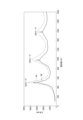
- 5 is a graph showing the analysis results of the absolute axial spring constant of the vibration-isolating bushing according to the first embodiment and the corresponding reference bushing.
- FIG. 11 is a front view showing an anti-vibration bushing according to another modified example as viewed from one side in the axial direction.
- FIG. 11 is a front view showing a vibration-isolating bushing according to still another modified example as viewed from one side in the axial direction.
- the vibration-damping bushing of the present invention is suitable for use, for example, in vehicle vibration-damping devices (e.g., engine mounts, motor mounts), and is particularly suitable for use in vibration-damping devices (e.g., motor mounts) for electric vehicles (EVs).
- vehicle vibration-damping devices e.g., engine mounts, motor mounts
- vibration-damping devices e.g., motor mounts
- EVs electric vehicles
- FIGS. 1 to 5 show an anti-vibration bushing 1 according to one embodiment of the present invention.
- the anti-vibration bushing 1 is suitable for use in, for example, vehicle anti-vibration devices (e.g., engine mounts, motor mounts), and is particularly suitable for use in anti-vibration devices (e.g., motor mounts) for electric vehicles (EVs).
- vehicle anti-vibration devices e.g., engine mounts, motor mounts
- anti-vibration devices e.g., motor mounts
- EVs electric vehicles
- Figs. 1 to 4 show the vibration-isolating bushing 1 when it is stationary and in its normal state.
- the vibration-isolating bushing 1 comprises an outer tube 2, an inner tube 3, and a rubber body 4.
- the inner cylinder 3 is coaxial with the outer cylinder 2 and is located on the inner peripheral side of the outer cylinder 2.
- the outer cylinder 2 and the inner cylinder 3 are made of, for example, metal and/or resin.
- the outer cylinder 2 is configured to be attached to either one of a vibration generating part (e.g., an engine or a motor) or a vibration receiving part (e.g., a vehicle body) during use.
- the inner cylinder 3 is configured to be attached to the other of the vibration generating part and the vibration receiving part during use.
- the outer cylinder 2 and the inner cylinder 3 each have a cylindrical shape, but may have any other cylindrical shape.
- the central axis O of the outer cylinder 2 is regarded as the central axis O of the vibration-proof bushing 1.
- the direction parallel to the central axis O of the vibration-proof bushing 1 is referred to as the "axial direction”.
- the axial direction may be oriented in any direction.
- the side farther from the center of the vibration-proof bushing 1 in the axial direction is referred to as the "axial outer side”
- the side closer to the center of the vibration-proof bushing 1 in the axial direction is referred to as the "axial inner side”
- the direction perpendicular to the central axis O of the vibration-proof bushing 1 is referred to as the "axial direction”.
- the side closer to the central axis O of the vibration-proof bushing 1 is referred to as the "inner peripheral side”
- the side farther from the central axis O of the vibration-proof bushing 1 is referred to as the “outer peripheral side”
- the circumferential direction centered on the central axis O of the vibration-proof bushing 1 is referred to as the "circumferential direction”
- the radial direction centered on the central axis O of the vibration-proof bushing 1 is referred to as the "radial direction”.
- the rubber body 4 is made of rubber, is located between the outer tube 2 and the inner tube 3 in the radial direction, and is generally tubular (in this embodiment, generally cylindrical). In this embodiment, the rubber body 4 is integrally constructed (i.e., made of a single member).
- the outer peripheral surface of the rubber body 4 is in contact with the inner peripheral surface of the outer tube 2 and is joined thereto by, for example, vulcanization adhesion.
- the inner peripheral surface of the rubber body 4 is in contact with the outer peripheral surface of the inner tube 3 and is joined thereto by, for example, vulcanization adhesion.
- the rubber body 4 has one or more (in this embodiment, one) main rubber parts 41, one or more (in this embodiment, one) grooves 42, and one or more (in this embodiment, one) stopper rubber parts 43.
- the boundaries between the various parts of the rubber body 4 are indicated by dashed lines.
- the main rubber part 41 connects the outer tube 2 and the inner tube 3 in the radial direction. That is, the main rubber part 41 extends continuously from the inner peripheral surface of the outer tube 2 to the outer peripheral surface of the inner tube 3 along the radial direction. Moreover, the main rubber part 41 extends only partially in the circumferential direction.
- the grooves 42 are through-holes that penetrate the rubber body 4 in the axial direction.
- "penetrating the rubber body 4 in the axial direction” is not limited to the case where the grooves 42 are surrounded by the rubber that constitutes the rubber body 4 over the entire circumference of the grooves 42 in a plan view as in the example of FIG. 1, but also includes the case where the grooves 42 directly face the outer tube 2 or the inner tube 3 without passing through the outer circumferential covering rubber part 46 or the inner circumferential covering rubber part 45 described below, thereby forming a groove (recess) that extends over the entire axial direction of the rubber body 4 and opens into the outer tube 2 or the inner tube 3.
- the grooves 42 are located only in the circumferential region other than the circumferential region in which the main rubber part 41 extends.
- the stopper rubber portion 43 faces the ridge 42 in the radial direction. That is, the stopper rubber portion 43 faces the ridge 42 in the radial direction, and the outer peripheral surface or the inner peripheral surface (the outer peripheral surface in this embodiment) of the stopper rubber portion 43 faces the ridge 42 and defines a part of the ridge 42.
- the stopper rubber portion 43 is located only in a circumferential region other than the circumferential region in which the main rubber portion 41 extends.
- the stopper rubber portion 43 is connected to the main rubber portion 41 at least at one end (both ends in this embodiment) in the circumferential direction of the stopper rubber portion 43 .
- the stopper rubber part 43 is connected to the main rubber part 41 so as to be able to move in direct cooperation with the main rubber part 41.
- the stopper rubber part 43 when the stopper rubber part 43 is connected to the main rubber part 41 only via a thin-film rubber part or the like provided on the inner peripheral surface of the outer tube 2 or the outer peripheral surface of the inner tube 3, the stopper rubber part 43 cannot move in cooperation with the main rubber part 41, and therefore it cannot be said that the stopper rubber part 43 is "connected so as to be able to move in direct cooperation with the main rubber part 41.”
- the stopper rubber portion 43 functions as a stopper that restricts excessive relative displacement between the inner tube 3 and the outer tube 2 in the axial direction.
- the stopper rubber portion 43 is configured such that while the inner tube 3 moves relative to the outer tube 2 in the axial direction in a direction narrowing the width of the groove 42, the stopper rubber portion 43 is compressed between the inner tube 3 and the outer tube 2 after the groove 42 is crushed, thereby restricting the inner tube 3 from approaching the outer tube 2 excessively in the axial direction. This improves the durability of the vibration-proof bushing 1.
- the stopper rubber part 43 faces the rib 42 in the radial direction and is connected to the main rubber part 41 so as to move directly in conjunction with the main rubber part 41. Therefore, as shown by the dashed line in Fig. 5, while the inner tube 3 vibrates in the axial direction relative to the outer tube 2, the stopper rubber part 43 can be displaced in the axial direction to the opposite side to the main rubber part 41. (Note that the dashed line in Fig. 5 shows that when the inner tube 3 is displaced to one side in the axial direction (the right side in Fig. 5), the main rubber part 41 is displaced to the other side in the axial direction (the left side in Fig.
- the stopper rubber part 43 is displaced to one side in the axial direction (the right side in Fig. 5).)
- the phase of the stopper rubber part 43 is not necessarily completely opposite to the phase of the main rubber part 41, but the stopper rubber part 43 can be at least partially displaced to the opposite side to the main rubber part 41 in the axial direction.
- a part of the force in either axial direction generated by the main rubber part 41 is offset by the force in the other axial direction generated by the stopper rubber part 43.
- the stopper rubber part 43 can function as a dynamic damper.
- the vibration-proof bushing 1 is able to suppress an increase in the absolute spring constant (dynamic spring constant) due to surging in the axial direction compared to the standard bushing B (FIG. 7), in other words, it is possible to reduce the spring constant in the axial direction.
- the reference bushing B does not have the grooves 42 and stopper rubber portion 43 of the vibration-isolating bushing 1, and the main rubber portion 41 of the vibration-isolating bushing 1 extends around the entire circumference (i.e., the main rubber portion 41 is extended so as to extend around the entire circumference), and the rubber body 4 is constructed only from the main rubber portion 41 that extends around the entire circumference.
- the vibration-isolating bushing 1 and the reference bushing B differ only in the above-mentioned points of the rubber body 4, and are the same in all other respects (outer diameter and material of the rubber body 4, and the configuration, dimensions, material, etc. of the outer tube 2 and inner tube 3).
- the mass of the stopper rubber portion 43 plays a particularly large role in determining how much the vibration-isolating bushing 1 can suppress the increase in absolute spring constant due to surging in the axial direction compared to the standard bushing B (i.e., how much the spring constant in the axial direction can be reduced), but the physical properties and material of the stopper rubber portion 43 also play a large role. It is also believed that the shapes of the stopper rubber portion 43 and the rim 42 can contribute to this to some extent. Furthermore, the smaller the difference between the surging frequency of the main rubber portion 41 and the surging frequency of the stopper rubber portion 43, the more effectively the stopper rubber portion 43 can function as a dynamic damper.
- the vibration-isolating bushings 1 of the examples falling within the scope of the present invention have secondary or tertiary peak values of the absolute spring constant in the axial direction that are 20% or more lower than those of the respective reference bushings B.
- Figures 8 to 13 show models of the rubber body 4 of each example used in the FEM analysis.
- Figure 8 shows the rubber body 4 of the reference bushing B corresponding to the vibration-isolating bushing 1 of each example shown in Figures 9 to 13.
- FIG. 9 10(a) to 10(d), 11(a) to 11(c), 12(a) to 12(c), and 13(a) to 13(c) each show the rubber body 4 of a vibration-isolating bushing 1 of a different example.
- Details of the rubber body 4 in each example of FIG. 8 to FIG. 13 are as shown in Tables 1 to 2 below.
- the rubber body 4 in each example of FIG. 8 to FIG. 13 had the same outer diameter, inner diameter, and axial length, and also had the same physical properties.
- the rubber body 4 in each example of FIG. 9 to FIG. 13 had a ridge 42 and a stopper rubber part 43 that faced the ridge 42 in the radial direction and was connected to the main rubber part 41 so as to move directly in conjunction with the main rubber part 41.
- the rubber body 4 of Example 1 shown in FIG. 9 had a configuration basically similar to that of the embodiment shown in FIG. 1 to FIG. 4, but differed from the embodiment shown in FIG. 1 to FIG. 4 in that the axial length L43 (FIG. 4) of the stopper rubber part 43 was the same as the axial length L41 (FIG. 4) of the main rubber part 41.
- the examples shown in FIG. 10 to FIG. 13 were different from Example 1 shown in FIG. 9 only by the "Difference in configuration from Example 1" described in Tables 1 to 2.
- the groove 42 has a circumferential groove portion 42a extending along the circumferential direction and a radial groove portion 42b extending radially inward from the circumferential center of the circumferential groove portion 42a, and the circumferential groove portion 42a has the same configuration as the groove 42 of Example 1 (FIG. 9).
- the stopper rubber portion 43 was provided on both sides of the radial groove portion 42b in the circumferential direction (two in total).
- angle range refers to the angle range centered on the central axis O.
- the angle range of the currant 42 in Example 1 (FIG. 9) was 90°.
- waveform W1 is a waveform of the result of the FEM analysis performed on the rubber body 4 of the standard bush B shown in FIG. 8
- waveform W2 is a waveform of the result of the FEM analysis performed on the rubber body 4 of the vibration-proof bush 1 of Example 1 shown in FIG. 9.
- the waveforms W1 and W2 of the absolute spring constant K in the axial direction of the standard bush B and the vibration-proof bush 1 of Example 1 each have three peaks, a primary peak, a secondary peak, and a tertiary peak, due to surging, and the peak value of the absolute spring constant K of the vibration-proof bush 1 of Example 1 was lower than that of the standard bush B at each of these three peaks.
- Table 1 shows, in percentage (%), how much the vibration-proof bush 1 of Example 1 was able to reduce the peak value of the absolute spring constant K compared to the standard bush B at each of the secondary peak and tertiary peak.
- the peak value of the secondary peak in the axial absolute spring constant K was specifically the value of the absolute spring constant K at 1000 Hz
- the peak value of the tertiary peak in the axial absolute spring constant K was specifically the value of the absolute spring constant K at 1600 Hz.
- the waveform of the absolute spring constant K in the axial direction had three peaks, similar to the anti-vibration bushing 1 of Example 1.
- the vibration-proof bushing 1 of each example of the present invention has a secondary peak value or tertiary peak value of the absolute spring constant in the axial direction that is 20% or more lower than that of the standard bushing B.
- the increase in the absolute spring constant due to surging in the axial direction can be suppressed (i.e., the spring constant can be reduced in the axial direction). Therefore, for example, when the vibration-proof bushing 1 is used as a vibration-proof device for a vehicle (e.g., an engine mount, a motor mount, and particularly, a vibration-proof device for an electric vehicle (EV) (e.g., a motor mount)), more desirable vibration-proof characteristics can be provided.
- a vibration-proof device for a vehicle e.g., an engine mount, a motor mount, and particularly, a vibration-proof device for an electric vehicle (EV) (e.g., a motor mount)
- EV electric vehicle
- a part of the force generated by the main rubber part 41 toward either one side in the axial direction is offset by the force generated by the stopper rubber part 43 toward the other side in the axial direction.
- the stopper rubber part 43 can function as a dynamic damper during vibration in the axial direction, it is possible to suppress the increase in the absolute spring constant due to surging in the axial direction, in other words, it is possible to reduce the springiness in the axial direction.
- the stopper rubber portion 43 is not connected to the main rubber portion 41, or if it is connected to the main rubber portion 41 (via a thin-film rubber portion, etc.) but is not designed to move in conjunction with the main rubber portion 41, the stopper rubber portion 43 will not be able to displace in the axial direction to the opposite side to the main rubber portion 41 during axial vibration, making it difficult for it to function as a dynamic damper and unable to suppress the increase in the absolute spring constant due to axial surging. Furthermore, in the vibration-isolating bushing 1 of each example of the present invention, as described above, the stopper rubber portion 43 also functions as a stopper that restricts excessive relative displacement in the axial direction between the inner tube 3 and the outer tube 2. Therefore, it is possible to achieve two points required for a vehicle vibration-isolating device, namely, low spring force in the axial direction and restriction of excessive displacement in the axial direction between the inner tube 3 and the outer tube 2, by using the same stopper rubber portion 43.
- only one of the secondary peak value and the tertiary peak value of the absolute spring constant in the axial direction may be 20% or more lower than the reference bushing B, but it is preferable that both the secondary peak value and the tertiary peak value are 20% or more lower.
- the following method for example, can be given as a method for determining the reduction rate of the secondary peak value or tertiary peak value of the absolute spring constant in the axial direction of an actual anti-vibration bushing 1 when compared with a reference bushing B.
- the anti-vibration bushing 1 first, the secondary peak value or tertiary peak value of the absolute spring constant in the axial direction of the anti-vibration bushing 1 in the actual product is determined by experiment, and the physical properties of the rubber body 4 of the anti-vibration bushing 1 in the actual product are determined by measurement or analysis.
- the rubber body 4 of the anti-vibration bushing 1 is then modeled for FEM analysis (i.e., has the same shape and size as the actual anti-vibration bushing 1), and the physical properties of the rubber body 4 of the anti-vibration bushing 1 in the actual product determined as described above are input into a model anti-vibration bushing 1 in which the rubber body 4 of the anti-vibration bushing 1 is modeled for FEM analysis (i.e., has the same shape and size as the actual anti-vibration bushing 1).
- the secondary peak value or tertiary peak value of the model anti-vibration bushing 1 is determined by FEM analysis, and the relationship between the secondary peak value or tertiary peak value between the anti-vibration bushing 1 in the actual product and the model anti-vibration bushing 1 is confirmed.
- the physical properties of the rubber body 4 of the vibration-proof bush 1 in the actual product obtained above are input into the model (model standard bush B) of the rubber body 4 of the standard bush B corresponding to the vibration-proof bush 1 created for FEM analysis, and the secondary peak value or tertiary peak value of the absolute spring constant in the axial direction of the rubber body 4 of the model standard bush B is obtained by FEM analysis, and the secondary peak value or tertiary peak value of the standard bush B in the hypothetical actual product is obtained based on the relationship between the secondary peak value or tertiary peak value of the absolute spring constant in the axial direction of the rubber body 4 of the model standard bush B and the secondary peak value or tertiary peak value between the vibration-proof bush 1 in the actual product and the model vibration-proof bush 1. Then, the reduction rate is calculated using the secondary peak value or tertiary peak value of the vibration-proof bush 1 in the actual product and the reference bush B in the hypothetical actual product obtained as described above.
- the vibration-isolating bushing 1 has a secondary peak value of the absolute spring constant in the axial direction that is 24% or more lower than that of the standard bushing B. From a similar viewpoint, it is preferable that the vibration-isolating bushing 1 has a tertiary peak value of the absolute spring constant in the axial direction that is 24% or more lower than that of the standard bushing B. Furthermore, compared to the standard bushing B, the secondary peak value of the absolute spring constant in the axial direction of the vibration-isolating bushing 1 may be lower by 40% or less, or may be lower by 37% or less. Furthermore, compared to the standard bushing B, the tertiary peak value of the absolute spring constant in the axial direction of the vibration-isolating bushing 1 may be lower by 40% or less, or may be lower by 37% or less.
- the groove 42 and the stopper rubber portion 43 can have various configurations.
- at least one stopper rubber portion 43 one in the examples shown in Fig. 1, Fig. 9, Fig. 10, Fig. 12, Fig. 13, and Fig. 15; two in the example shown in Fig. 11
- may be located radially inside at least a part of the groove 42 the whole of the groove 42 in the examples shown in Fig. 1, Fig. 9, Fig. 10, Fig. 12, Fig. 13, and Fig. 15; only the circumferential groove portion 42a of the groove 42 in the example shown in Fig. 11).
- the at least one stopper rubber portion 43 faces the at least a part of the groove 42 in the radial direction.
- the stopper rubber portion 43 that links with the main rubber portion 41 can be easily formed.
- the rubber body 4 may have an outer peripheral covering rubber part 46 between the ridge 42 and the outer tube 2.
- the outer peripheral surface of the outer peripheral covering rubber part 46 is in contact with (and joined to) the inner peripheral surface of the outer tube 2.
- the outer peripheral covering rubber part 46 has both circumferential ends connected to the main body rubber part 41, but is not configured to be able to move in conjunction with the main body rubber part 41.
- the outer peripheral covering rubber part 46 may not be provided between the ridge 42 and the outer tube 2, and a part of the ridge 42 may be defined by a part of the inner peripheral surface of the outer tube 2.
- the rubber body 4 may have an inner covering rubber part 45 between the stopper rubber part 43 and the inner tube 3.
- the inner surface of the inner covering rubber part 45 is in contact with (and joined to) the outer surface of the inner tube 3.
- the inner covering rubber part 45 has both circumferential ends connected to the main rubber part 41, but is not configured to be able to move in conjunction with the main rubber part 41.
- At least one (one in the example of Fig. 17) stopper rubber part 43 may be located radially outward of at least a portion of the ridge 42 (the entire ridge 42 in the example of Fig. 17).
- the at least one stopper rubber part 43 faces the at least a portion of the ridge 42 in the radial direction.
- the stopper rubber part 43 that interlocks with the main body rubber part 41 can be easily formed.
- the rubber body 4 may or may not have an outer circumferential covering rubber part 46 between the stopper rubber part 43 and the outer tube 2.
- the rubber body 4 may or may not have an inner circumferential covering rubber part 45 between the ridge 42 and the inner tube 3.
- the grooves 42 may extend along the circumferential direction.
- the grooves 42 may have a circumferential groove portion 42a extending along the circumferential direction and a radial groove portion 42b extending radially outward from an arbitrary position (for example, the circumferential center) of the circumferential groove portion 42a.
- the stopper rubber portion 43 may be provided on both sides of the radial groove portion 42b in the circumferential direction (two in total).
- the grooves 42 may have any other shape.
- two grooves 42 may be disposed at a distance from each other in the radial direction, and at least one (one in the example of Fig. 18) stopper rubber portion 43 may be disposed between these two grooves 42.
- the at least one stopper rubber portion 43 faces each of these two grooves 42 in the radial direction.
- the stopper rubber portion 43 that links with the main rubber portion 41 can be easily formed.
- the rubber body 4 may or may not have an outer circumferential covering rubber part 46 between one of the grooves 42 and the outer tube 2.
- the rubber body 4 may or may not have an inner circumferential covering rubber part 45 between the other groove 42 and the inner tube 3.
- the axial length L43 ( Figure 4) of the stopper rubber part 43 is equal to or less than the axial length L41 ( Figure 4) of the main rubber part 41.
- L43 L41
- L43 ⁇ L41 L41.
- the stopper rubber portion 43 refers to the minimum axial length when the axial length of the stopper rubber portion 43 is nonuniform along the radial direction and/or the circumferential direction.
- the axial length L41 (FIG. 4) of the main body rubber portion 41 refers to the minimum axial length when the axial length of the main body rubber portion 41 is nonuniform along the radial direction and/or the circumferential direction.
- the rubber body 4 may further have a circumferential rubber mass portion 44 that protrudes axially outward from at least one axial end face of the main rubber portion 41 and extends circumferentially.
- a circumferential rubber mass portion 44 that protrudes axially outward from at least one axial end face of the main rubber portion 41 and extends circumferentially.
- the increase in the absolute spring constant due to surging in the axial direction can be further suppressed, and the increase in the absolute spring constant due to surging in the direction perpendicular to the axis can also be suppressed.
- Fig. 15 shows a model of yet another example of the rubber body 4 used in the above-mentioned FEM analysis.
- the rubber body 4 in the example of Fig. 15 corresponds to the rubber body 4 in the example of Fig.
- the rubber body 4 of the reference bush B corresponding to the vibration-proof bushing 1 equipped with the rubber body 4 in the example of Fig. 15 is that shown in Fig. 8.
- the graph in Fig. 16 is similar to the graph in Fig. 14, with waveform W1 being the waveform resulting from the FEM analysis performed on the rubber body 4 of the standard bushing B shown in Fig. 8, and waveform W3 being the waveform resulting from the FEM analysis performed on the rubber body 4 of the vibration-isolating bushing 1 of the example shown in Fig. 15.
- waveform W1 being the waveform resulting from the FEM analysis performed on the rubber body 4 of the standard bushing B shown in Fig. 8
- waveform W3 being the waveform resulting from the FEM analysis performed on the rubber body 4 of the vibration-isolating bushing 1 of the example shown in Fig. 15.
- the waveform W3 (Fig. 16) of the vibration-isolating bushing 1 of the example shown in Fig. 15 was able to reduce the secondary peak value of the absolute spring constant K relative to the waveform W1 of the standard bushing B even more than the waveform W2 (Fig. 14) of the vibration-isolating bushing 1 of the example shown in Fig. 9.
- the rubber body 4 is preferably formed from a rubber obtained by crosslinking a rubber composition containing a rubber component whose main components are natural rubber and non-diene rubber. This makes it possible to further suppress an increase in the absolute spring constant due to surging.
- rubber component mainly composed of natural rubber and non-diene rubber refers to a rubber component that contains natural rubber and non-diene rubber as rubber components, and the total amount of the natural rubber and non-diene rubber in the rubber component is 50 mass% or more based on the total amount of the rubber component. It is more preferable that the total amount of the natural rubber and non-diene rubber in the rubber component is more than 50 mass% based on the total amount of the rubber component.
- the rubber component may contain only natural rubber and non-diene rubber, or may contain rubber other than natural rubber and non-diene rubber.
- An example of the rubber other than natural rubber and non-diene rubber is diene rubber.
- the blending ratio of the natural rubber to the non-diene rubber in the rubber composition is preferably 95:5 to 50:50 by mass, more preferably 95:5 to 60:40, even more preferably 95:5 to 65:35, and even more preferably 80:20 to 70:30.
- the natural rubber (NR) is not particularly limited and may be any known rubber that is appropriately selected and used. Examples of the natural rubber include RSS (ribbed smoked sheets) and TSR (Technically Specified Rubber).
- the non-diene rubber is not particularly limited and may be appropriately selected from known rubbers.
- examples of such rubbers include butyl rubber (IIR), chlorinated butyl rubber (CIIR), brominated butyl rubber (BIIR), ethylene-propylene-norbornene rubber (EPDM), ethylene-acrylic rubber (AEM), polyacrylic rubber (ACM), silicone rubber (VMQ), fluororubber (FKM), polyurethane rubber (AU), ester-based polyurethane rubber (EU), polyether ether ketone rubber (PEEK), and the like.
- butyl rubber (IIR), chlorinated butyl rubber (CIIR), or brominated butyl rubber (BIIR) is particularly preferred.
- the rubber forming the rubber body 4 does not have to be the above-mentioned rubber, and may be a combination of two or more kinds of rubber.
- the vibration-damping bushing of the present invention is suitable for use in vehicle vibration-damping devices (e.g., engine mounts, motor mounts), and is particularly suitable for use in vibration-damping devices (e.g., motor mounts) for electric vehicles (EVs).
- vehicle vibration-damping devices e.g., engine mounts, motor mounts
- vibration-damping devices e.g., motor mounts
- EVs electric vehicles
Landscapes
- Engineering & Computer Science (AREA)
- General Engineering & Computer Science (AREA)
- Mechanical Engineering (AREA)
- Chemical & Material Sciences (AREA)
- Combustion & Propulsion (AREA)
- Physics & Mathematics (AREA)
- Acoustics & Sound (AREA)
- Aviation & Aerospace Engineering (AREA)
- Springs (AREA)
- Vibration Prevention Devices (AREA)
Abstract
Priority Applications (2)
| Application Number | Priority Date | Filing Date | Title |
|---|---|---|---|
| CN202480035079.3A CN121195121A (zh) | 2023-07-14 | 2024-06-28 | 防振衬套 |
| JP2025533944A JPWO2025018128A1 (fr) | 2023-07-14 | 2024-06-28 |
Applications Claiming Priority (2)
| Application Number | Priority Date | Filing Date | Title |
|---|---|---|---|
| JP2023-116281 | 2023-07-14 | ||
| JP2023116281 | 2023-07-14 |
Publications (1)
| Publication Number | Publication Date |
|---|---|
| WO2025018128A1 true WO2025018128A1 (fr) | 2025-01-23 |
Family
ID=94281339
Family Applications (1)
| Application Number | Title | Priority Date | Filing Date |
|---|---|---|---|
| PCT/JP2024/023594 Pending WO2025018128A1 (fr) | 2023-07-14 | 2024-06-28 | Douille résistant aux vibrations |
Country Status (3)
| Country | Link |
|---|---|
| JP (1) | JPWO2025018128A1 (fr) |
| CN (1) | CN121195121A (fr) |
| WO (1) | WO2025018128A1 (fr) |
Citations (3)
| Publication number | Priority date | Publication date | Assignee | Title |
|---|---|---|---|---|
| JPS6360733U (fr) * | 1986-10-09 | 1988-04-22 | ||
| JPH0442937U (fr) * | 1990-08-09 | 1992-04-13 | ||
| WO2020175640A1 (fr) | 2019-02-28 | 2020-09-03 | 住友理工株式会社 | Dispositif antivibratoire cylindrique pour support de moteur |
-
2024
- 2024-06-28 JP JP2025533944A patent/JPWO2025018128A1/ja active Pending
- 2024-06-28 CN CN202480035079.3A patent/CN121195121A/zh active Pending
- 2024-06-28 WO PCT/JP2024/023594 patent/WO2025018128A1/fr active Pending
Patent Citations (3)
| Publication number | Priority date | Publication date | Assignee | Title |
|---|---|---|---|---|
| JPS6360733U (fr) * | 1986-10-09 | 1988-04-22 | ||
| JPH0442937U (fr) * | 1990-08-09 | 1992-04-13 | ||
| WO2020175640A1 (fr) | 2019-02-28 | 2020-09-03 | 住友理工株式会社 | Dispositif antivibratoire cylindrique pour support de moteur |
Also Published As
| Publication number | Publication date |
|---|---|
| JPWO2025018128A1 (fr) | 2025-01-23 |
| CN121195121A (zh) | 2025-12-23 |
Similar Documents
| Publication | Publication Date | Title |
|---|---|---|
| KR101648427B1 (ko) | 다이나믹 댐퍼 | |
| CN107218345B (zh) | 动态减振器组件 | |
| JP5603390B2 (ja) | 筒形防振装置 | |
| CN106864240B (zh) | 安装支架的结构 | |
| CN110709612A (zh) | 支承衬套 | |
| GB2412150B (en) | Resin torque rod and method of producing the same | |
| CN109863321A (zh) | 用于轴支承的弹性主体和轴支承 | |
| JP7362953B2 (ja) | 防振装置 | |
| WO2021085029A1 (fr) | Renfort amortisseur de carrosserie de véhicule | |
| WO2025018128A1 (fr) | Douille résistant aux vibrations | |
| GB2534240A (en) | Bushing, in particular for a vehicle | |
| JP7079784B2 (ja) | 電気自動車用の筒形モータマウント | |
| CN110529545B (zh) | 充液式防振装置 | |
| JP2018159455A (ja) | 筒形防振装置 | |
| KR930008514B1 (ko) | 자동차 동력계 장착장치 | |
| KR101687694B1 (ko) | 차량용 2중 절연 하이드로 마운트 | |
| CN206386428U (zh) | 筒形防振装置 | |
| JP2024126640A (ja) | モータマウント用筒型防振装置 | |
| JP5876365B2 (ja) | 筒型防振装置 | |
| JP6297389B2 (ja) | 防振装置 | |
| JP6718729B2 (ja) | 防振ブッシュ | |
| US12253135B2 (en) | Tubular vibration-damping device | |
| JP3392202B2 (ja) | ダイナミックダンパ | |
| JP4666692B2 (ja) | 防振ブッシュおよびその製造方法 | |
| CN115929837B (zh) | 具有不同弹性表现的弹性连接件 |
Legal Events
| Date | Code | Title | Description |
|---|---|---|---|
| 121 | Ep: the epo has been informed by wipo that ep was designated in this application |
Ref document number: 24842922 Country of ref document: EP Kind code of ref document: A1 |
|
| ENP | Entry into the national phase |
Ref document number: 2025533944 Country of ref document: JP Kind code of ref document: A |
|
| WWE | Wipo information: entry into national phase |
Ref document number: 2025533944 Country of ref document: JP |
|
| WWE | Wipo information: entry into national phase |
Ref document number: 2024842922 Country of ref document: EP |
|
| NENP | Non-entry into the national phase |
Ref country code: DE |