WO2025018317A1 - Matériau de fil - Google Patents
Matériau de fil Download PDFInfo
- Publication number
- WO2025018317A1 WO2025018317A1 PCT/JP2024/025376 JP2024025376W WO2025018317A1 WO 2025018317 A1 WO2025018317 A1 WO 2025018317A1 JP 2024025376 W JP2024025376 W JP 2024025376W WO 2025018317 A1 WO2025018317 A1 WO 2025018317A1
- Authority
- WO
- WIPO (PCT)
- Prior art keywords
- wire
- content
- lamellar spacing
- true
- wire rod
- Prior art date
- Legal status (The legal status is an assumption and is not a legal conclusion. Google has not performed a legal analysis and makes no representation as to the accuracy of the status listed.)
- Pending
Links
Images



Classifications
-
- C—CHEMISTRY; METALLURGY
- C22—METALLURGY; FERROUS OR NON-FERROUS ALLOYS; TREATMENT OF ALLOYS OR NON-FERROUS METALS
- C22C—ALLOYS
- C22C38/00—Ferrous alloys, e.g. steel alloys
-
- C—CHEMISTRY; METALLURGY
- C22—METALLURGY; FERROUS OR NON-FERROUS ALLOYS; TREATMENT OF ALLOYS OR NON-FERROUS METALS
- C22C—ALLOYS
- C22C38/00—Ferrous alloys, e.g. steel alloys
- C22C38/06—Ferrous alloys, e.g. steel alloys containing aluminium
-
- C—CHEMISTRY; METALLURGY
- C22—METALLURGY; FERROUS OR NON-FERROUS ALLOYS; TREATMENT OF ALLOYS OR NON-FERROUS METALS
- C22C—ALLOYS
- C22C38/00—Ferrous alloys, e.g. steel alloys
- C22C38/18—Ferrous alloys, e.g. steel alloys containing chromium
- C22C38/40—Ferrous alloys, e.g. steel alloys containing chromium with nickel
- C22C38/54—Ferrous alloys, e.g. steel alloys containing chromium with nickel with boron
-
- C—CHEMISTRY; METALLURGY
- C21—METALLURGY OF IRON
- C21D—MODIFYING THE PHYSICAL STRUCTURE OF FERROUS METALS; GENERAL DEVICES FOR HEAT TREATMENT OF FERROUS OR NON-FERROUS METALS OR ALLOYS; MAKING METAL MALLEABLE, e.g. BY DECARBURISATION OR TEMPERING
- C21D8/00—Modifying the physical properties of ferrous metals or ferrous alloys by deformation combined with, or followed by, heat treatment
- C21D8/06—Modifying the physical properties of ferrous metals or ferrous alloys by deformation combined with, or followed by, heat treatment during manufacturing of rods or wires
Definitions
- This disclosure relates to wire rods, and more specifically, to wire rods suitable for use as materials for steel cords and bead wires in automobile tires, bridge wires, and the like.
- Steel wire such as steel cord made from wire rod is manufactured, for example, by the following manufacturing method.
- the steel wire is brass plated and then final wet wire drawing to make a steel wire with a wire diameter of 0.15 to 0.40 mm.
- multiple steel wires are twisted together to make a twisted steel wire.
- steel cord is manufactured.
- Bead wire, bridge wire, etc. are manufactured by patenting wire rod after hot rolling, and twisting it to make a twisted steel wire after wire drawing.
- Patent Document 1 International Publication No. WO 2018/117157
- Patent Document 2 International Publication No. WO 2016/021556
- the wire material disclosed in Patent Document 1 has chemical components, in mass%, of C: 0.90-1.20%, Si: 0.10-1.00%, Mn: 0.20-0.80%, Cr: 0.10-0.40%, Al: 0-0.002%, Ti: 0-0.002%, N: 0-0.0050%, P: 0-0.020%, S: 0-0.010%, O: 0-0.0040%, Mo: 0-0.20%, B: 0-0.0030%, with the balance being Fe and impurities.
- the average value of %Mn+2 ⁇ %Cr throughout the wire material is 0.50-1.00%.
- the metal structure is 90% or more by area fraction of pearlite, the remainder being one or more of ferrite, cementite, and bainite, and the area fraction of cementite is less than 3%.
- the maximum grain size of TiN is less than 15 ⁇ m.
- %Mn and %Cr represent the contents of Mn and Cr in mass%.
- the wire drawability of this wire is improved by adjusting the chemical composition, the metal structure mainly composed of pearlite, the size of TiN, and the segregation of Mn and Cr.
- the wire rod disclosed in Patent Document 2 has a chemical composition, in mass%, of C: 0.70-1.20%, Si: 0.10-1.2%, Mn: 0.10-1.0%, P: 0.001-0.012%, S: 0.001-0.010%, N: 0.0010-0.0050%, and the balance of Fe and impurities.
- the area ratio of pearlite is 95% to 100%
- the average block grain size of pearlite is 10 ⁇ m to 30 ⁇ m
- the standard deviation of the block grain size is 20 ⁇ m or less.
- C (%), Si (%), and Mn (%) are the contents in mass% of C, Si, and Mn, respectively, and Ceq.
- the drawability is improved by adjusting the pearlite block size.
- Patent Document 3 unlike Patent Documents 1 and 2, the lamellar spacing of pearlite is adjusted to improve wiredrawability.
- the wire rod disclosed in Patent Document 3 contains, by mass%, C: 0.68-0.86%, Si: 0.05-0.5%, Mn: 0.1-0.8%, with the remainder being Fe and unavoidable impurities.
- the microstructure of this wire rod has pearlite of 95 area % or more, the average lamellar spacing L of this pearlite is in the range of 150-300 nm, the area of the lamellae of this pearlite having a spacing of 120 nm or less is 30% or less, and the standard deviation of the lamellar spacing is 50 nm or less.
- the average nodule diameter D of this pearlite is 40 ⁇ m or less, and the average nodule diameter D and the average lamellar spacing L satisfy the relationship D ⁇ -0.1 ⁇ L + 60.
- Patent Documents 1 to 3 can also improve the wiredrawability of wire rods.
- other techniques may also be used to improve the wiredrawability of wire rods.
- the object of the present invention is to provide a wire rod with excellent wire drawing processability.
- the wire material disclosed herein has a chemical composition, in mass%, of C: 0.70-1.20%, Si: 0.10-1.50%, Mn: 0.10-1.00%, P: 0.020% or less, S: 0.020% or less, Al: 0.080% or less, N: 0.0010-0.0100%, O: 0.0050% or less, Cr: 0-0.50%, Co: 0-0.50%, Cu: 0-0.50%, Ni: 0-0.50%, Mo: 0-0.20%, B: 0-0.005%, W: 0-0.20%, Ti: 0-0.10%, Nb: 0-0.10%, Sn: 0-0.10%, As: 0-0.050%, Sb: 0-0.050%, V: 0-0.10%, Ca: 0-0.0050%, Mg: 0-0.0050%, Zr: 0-0.010%, and rare earth elements: 0-0.0050%, with the balance being Fe and impurities.
- LmaxS/LaveS is 1.70 or less.
- FWHMs full width at half maximum of the true lamellar spacing at a depth of 0.5 mm from the surface of the wire
- FWHMc full width at half maximum of the true lamellar spacing at the center of the wire
- the wire rod of the present invention has excellent wire drawing processability.
- FIG. 1 is a schematic diagram for explaining the apparent pearlite lamellar spacing and the true pearlite lamellar spacing in microstructural observation.
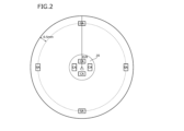
- FIG. 2 is a schematic diagram showing an example of an observation surface when a cross section perpendicular to the axial direction of a wire is used as the observation surface.
- FIG. 3 is a schematic diagram in which the observation field in FIG. 2 is divided into a plurality of minute sections.
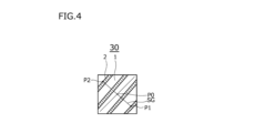
- FIG. 4 is a schematic diagram of the micro-compartment in FIG.
- FIG. 5 is a schematic diagram of another microcompartment different from FIG.
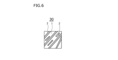
- FIG. 6 is a schematic diagram of another microcompartment different from those in FIGS.
- the inventors first investigated the chemical composition of wire rod suitable for use in steel cords, bead wires, bridge wires, etc. As a result, the chemical composition was found to be, by mass, C: 0.70-1.20%, Si: 0.10-1.50%, Mn: 0.10-1.00%, P: 0.020% or less, S: 0.020% or less, Al: 0.080% or less, N: 0.0010-0.0100%, O: 0.0050% or less, Cr: 0-0.50%, Co: 0-0.50%, Cu: 0-0.50%, Ni: 0-0.50%, Mo: 0-0.20%, B: 0-0.005%, W: 0.005%.
- Patent Document 3 seeks the "apparent lamellar spacing" of pearlite observed in microstructural observation of a two-dimensional cross section of the wire rod. Usually, microstructure observation is performed on a two-dimensional observation surface.
- a distance ⁇ a which is a minimum distance between adjacent lamellar cementite 2 in pearlite on the observation surface 10 which is a two-dimensional plane is defined as "apparent lamellar spacing ⁇ a ".
- the distance ⁇ t which is the minimum distance between adjacent lamellar cementite 2 in pearlite in a three-dimensional space is defined as the "true lamellar spacing ⁇ t ".
- the apparent lamellar spacing ⁇ a varies greatly depending on the angle ⁇ between the observation surface 10, which is a two-dimensional plane, and the extending direction of the lamellar ferrite 1 and the lamellar cementite 2. Therefore, in many cases, the apparent lamellar spacing ⁇ a is different from the true lamellar spacing ⁇ t .
- Patent Document 3 a local region with a small lamellar spacing is selected from the apparent lamellar spacing ⁇ a in the observation surface, and the apparent lamellar spacing of the local region is obtained.
- the present inventors have found that the distribution state of the true lamellar spacing ⁇ t in a wire, which has not been investigated so far, can be obtained by using the following method.
- Step 1 Obtaining a scanning electron microscope (SEM) observation image
- Step 2 Measuring the apparent lamellar spacing distribution
- Step 3 Measuring the true lamellar spacing distribution
- the apparent lamellar spacing ⁇ a means the distance between adjacent lamellar cementite observed in the SEM observation image, which is a two-dimensional plane, as described above.
- the true lamellar spacing ⁇ t means the distance between the actual lamellar cementite plates in three-dimensional space.
- the true lamellar spacing ⁇ t does not appear on the observation surface 10, so it cannot be observed in the SEM observation image. Therefore, in this embodiment, a mathematical approach is used to obtain the true lamellar spacing ⁇ t based on the apparent lamellar spacing ⁇ a . Each step will be described below.
- Step 1 Acquiring SEM observation image
- the wire is cut perpendicular to the axial direction (longitudinal direction), and the cross section (cross section perpendicular to the axial direction of the wire) is used as the observation surface.
- FIG. 2 is a schematic diagram showing an example of the observation surface.
- Mirror polishing is performed on the observation surface 10.
- the observation surface 10 is etched using picral for about 7 seconds to reveal the microstructure on the observation surface 10.
- SEM observation is performed at an acceleration voltage of 15 kv and a magnification of 2000 times to obtain SEM images. Specifically, as shown in FIG.
- observation fields SA of 5120 pixels in the circumferential direction and 3840 pixels in the radial direction of the observation surface 10 are selected at 90° pitches around the center point C1 of the observation surface 10, with the center at a depth position of 0.5 mm from the surface.
- the area of the observation field SA is a rectangle with a circumference of 60 ⁇ m (5120 pixels) and a diameter of 45 ⁇ m (3840 pixels).
- the four observation fields SA are referred to as observation fields SA of the surface layer region.
- observation fields CA are selected from the central region 20, which is a circular region with a radius of D/8 (D is the diameter of the wire) centered on the center C1 of the observation surface 10.
- Each observation field CA is a rectangle with 5120 pixels in the circumferential direction and 3840 pixels in the radial direction, and the area of each observation field CA is a rectangle with 60 ⁇ m (5120 pixels) in the circumferential direction and 45 ⁇ m (3840 pixels) in the radial direction.
- the center position of each observation field CA is D/16 in the radial direction from the center point C1.
- the four observation fields CA are referred to as the observation fields CA of the central region.
- the SEM device used is, for example, a JSM-7100F manufactured by JEOL Ltd.
- Step 2 Measurement of the distribution of apparent lamellar spacing ⁇ a ] Using the observation field SA of the surface region and the observation field CA of the central region, the distribution of apparent lamellar spacing ⁇ a obtained from two-dimensional planar SEM images in the surface region and the central region is obtained.
- the SEM image is divided into minute sections 30 of 50 pixels x 50 pixels (0.586 ⁇ m x 0.586 ⁇ m). Since the SEM image is 5120 pixels x 3840 pixels, when the SEM image is divided into minute sections 30, there are regions that do not become 50 pixels x 50 pixels. These regions are not subject to measurement of the apparent lamellar spacing ⁇ a .
- FIG. 4 is a schematic diagram showing an example of the minute partition 30.
- the apparent lamellar spacing ⁇ a is obtained by the following method.
- the length of the line segment is the length between the two most distant intersections P1 and P2 of the intersections between the line segment and the lamellar cementite 2.
- L0 in the determined line segment is set as the apparent lamellar spacing ⁇ a (nm) in the minute partition 30.
- the number of intersections between the line segment SG and the lamellar cementite is "4".
- the micro-compartment 30 is excluded from the measurement target of the apparent lamellar spacing ⁇ a .
- Step 3 Measurement of true lamellar spacing distribution
- the distribution of apparent lamellar spacing ⁇ a obtained from a two-dimensional SEM image is different from the distribution of true lamellar spacing ⁇ t in the wire. Therefore, the distribution of apparent lamellar spacing ⁇ a obtained in step 2 is fitted with formula (a) to obtain the distribution of true lamellar spacing ⁇ t .
- formula (a) is an equation showing the relationship between the distribution of apparent lamellar spacing ⁇ a and the distribution of true lamellar spacing ⁇ t .
- ⁇ a is the apparent lamellar spacing
- ⁇ t is the true lamellar spacing
- ⁇ ( ⁇ a ) is the distribution of the apparent lamellar spacing
- G( ⁇ t ) is the distribution of the true lamellar spacing ⁇ t .
- G( ⁇ t ) is a Gaussian distribution function, as shown in formula (b).
- A, B, and C in formula (b) are fitting parameters.
- the apparent lamellar spacing ⁇ a depends on the lamellar orientation angle ⁇ shown in Fig. 1. Therefore, it is necessary to convert the apparent lamellar spacing ⁇ a to the true lamellar spacing ⁇ t . As shown in Fig. 1, the apparent lamellar spacing ⁇ a and the true lamellar spacing ⁇ t satisfy the formula (1).
- the full width at half maximum FWHMc of the distribution of the true lamellar spacing ⁇ t is obtained.
- the inventors found that when the average lamellar spacing at a depth of 0.5 mm from the surface of the wire in a circular cross section perpendicular to the axial direction of the wire is LaveS (nm) and the maximum lamellar spacing is LmaxS (nm), if LmaxS/LaveS is 1.70 or less, the wiredrawability is improved.
- the inventors investigated the relationship between the distribution of lamellar spacing in the surface region of a circular cross section, the distribution of lamellar spacing in the central region, and wiredrawability. As a result, they found that when the full width at half maximum of the lamellar spacing at a depth of 0.5 mm from the surface of the wire in the circular cross section is FWHMs (nm) and the full width at half maximum of the lamellar spacing at the central position of the wire is FWHMc (nm), excellent wiredrawability can be obtained if FWHMc/FWHMs is 1.10 to 2.00.
- the gist of the wire of the present invention which was completed based on the above findings, is as follows:
- the chemical composition of the wire of the first configuration is, in mass%, C: 0.70-1.20%, Si: 0.10-1.50%, Mn: 0.10-1.00%, P: 0.020% or less, S: 0.020% or less, Al: 0.080% or less, N: 0.0010-0.0100%, O: 0.0050% or less, Cr: 0-0.50%, Co: 0-0.50%, Cu: 0-0.50%, Ni: 0-0.50%, Mo 0-0.20%, B: 0-0.005%, W: 0-0.20%, Ti: 0-0.10%, Nb: 0-0.10%, Sn: 0-0.10%, As: 0-0.050%, Sb: 0-0.050%, V: 0-0.10%, Ca: 0-0.0050%, Mg: 0-0.0050%, Zr: 0-0.010%, and rare earth elements: 0-0.0050%, with the balance being Fe and impurities.
- LmaxS/LaveS is 1.70 or less.
- FWHMs full width at half maximum of the true lamellar spacing at a depth of 0.5 mm from the surface of the wire
- FWHMc full width at half maximum of the true lamellar spacing at the center of the wire
- the wire of the second configuration is the wire of the first configuration, and contains, in mass%, one or more elements selected from the group consisting of Cr: 0.01-0.50%, Co: 0.01-0.50%, Cu: 0.01-0.50%, Ni: 0.01-0.50%, Mo: 0.01-0.20%, B: 0.001-0.005%, W: 0.01-0.20%, Ti: 0.01-0.10%, Nb: 0.01-0.10%, Sn: 0.01-0.10%, As: 0.001-0.050%, Sb: 0.001-0.050%, and V: 0.01-0.10%.
- the chemical composition of the wire of the third configuration is, in mass%, C: 0.70-1.20%, Si: 0.10-1.50%, Mn: 0.10-1.00%, P: 0.020% or less, S: 0.020% or less, Al: 0.080% or less, N: 0.0010-0.0100%, O: 0.0050% or less, Cr: 0-0.50%, Co: 0-0.50%, Cu: 0-0.50%, N i: 0-0.50%, Mo: 0-0.20%, B: 0-0.005%, W: 0-0.20%, Ti: 0-0.10%, Nb: 0-0.10%, Sn: 0-0.10%, V: 0-0.10%, Ca: 0-0.0050%, Mg: 0-0.0050%, Zr: 0-0.010%, and rare earth elements: 0-0.0050%, with the balance being Fe and impurities.
- LmaxS/LaveS is 1.70 or less.
- FWHMs full width at half maximum of the true lamellar spacing at a depth of 0.5 mm from the surface of the wire
- FWHMc full width at half maximum of the true lamellar spacing at the center of the wire
- the wire rod of the fourth configuration is the wire rod of the third configuration, and contains, in mass %, one or more elements selected from the group consisting of Cr: 0.01-0.50%, Co: 0.01-0.50%, Cu: 0.01-0.50%, Ni: 0.01-0.50%, Mo: 0.01-0.20%, B: 0.001-0.005%, W: 0.01-0.20%, Ti: 0.01-0.10%, Nb: 0.01-0.10%, Sn: 0.01-0.10%, and V: 0.01-0.10%.
- the wire of the fifth configuration is a wire of the first to fourth configurations, and contains, in mass %, one or more elements selected from the group consisting of Ca: 0.0001-0.0050%, Mg: 0.0001-0.0050%, Zr: 0.001-0.010%, and rare earth elements: 0.0001-0.0050%.
- the wire of the present embodiment includes the following features 1 to 3.
- the chemical composition, in mass%, is C: 0.70-1.20%, Si: 0.10-1.50%, Mn: 0.10-1.00%, P: 0.020% or less, S: 0.020% or less, Al: 0.080% or less, N: 0.0010-0.0100%, O: 0.0050% or less, Cr: 0-0.50%, Co: 0-0.50%, Cu: 0-0.50%, Ni: 0-0.50%, Mo: 0-0.2 0%, B: 0-0.005%, W: 0-0.20%, Ti: 0-0.10%, Nb: 0-0.10%, Sn: 0-0.10%, As: 0-0.050%, Sb: 0-0.050%, V: 0-0.10%, Ca: 0-0.0050%, Mg: 0-0.0050%, Zr: 0-0.010%, and rare earth elements: 0-0.0050%, with the balance being Fe and impurities.
- C 0.70-1.20% Carbon (C) increases the strength of the wire rod. If the C content is less than 0.70%, the above effect cannot be sufficiently obtained even if the contents of other elements are within the range of this embodiment. . On the other hand, if the C content exceeds 1.20%, even if the contents of other elements are within the range of this embodiment, pro-eutectoid cementite is excessively generated. In this case, the wire drawability of the wire rod is deteriorated. Decreases. Therefore, the C content is 0.70 to 1.20%.
- the lower limit of the C content is preferably 0.72%, more preferably 0.78%, further preferably 0.80%, and further preferably 0.82%.
- the upper limit of the C content is preferably 1.18%, more preferably 1.12%, further preferably 1.08%, and further preferably 1.05%.
- Si 0.10 ⁇ 1.50%
- Silicon (Si) increases the strength of the wire rod.
- Si deoxidizes the steel during the steelmaking process in the wire rod manufacturing process. If the Si content is less than 0.10%, the other element contents Even within the scope of this embodiment, the above-mentioned effects cannot be obtained sufficiently.
- the Si content exceeds 1.50%, even if the contents of other elements are within the ranges of this embodiment, Si will segregate in the wire material that is the raw material for the steel wire. Bainite forms in the segregated regions, deteriorating the drawability of the wire rod. Therefore, the Si content is 0.10 to 1.50%.
- the lower limit of the Si content is preferably 0.15%, more preferably 0.20%, and further preferably 0.25%.
- the upper limit of the Si content is preferably 1.42%, more preferably 1.35%, still more preferably 1.00%, still more preferably 0.90%, and still more preferably 0.80%. %.
- Mn 0.10-1.00%
- Mn Manganese
- Mn content is less than 0.10% If this is the case, even if the contents of other elements are within the ranges of this embodiment, the above-mentioned effects cannot be sufficiently obtained.
- Mn content exceeds 1.00%, Mn will segregate in the wire rod even if the contents of other elements are within the ranges of this embodiment. In this case, bainite will form in the region where Mn is segregated. This reduces the drawability of the wire rod. Therefore, the Mn content is 0.10 to 1.00%.
- the lower limit of the Mn content is preferably 0.12%, more preferably 0.20%, and further preferably 0.25%.
- the upper limit of the Mn content is preferably 0.90%, more preferably 0.85%, further preferably 0.80%, and further preferably 0.70%.
- Phosphorus (P) is an impurity. If the P content exceeds 0.020%, P segregates at grain boundaries even if the contents of other elements are within the ranges of this embodiment. As a result, the grain boundaries become embrittled, and the wire drawability of the wire rod decreases. Therefore, the P content is 0.020% or less. It is preferable that the P content is as low as possible. However, excessive reduction in the P content increases the production cost. Therefore, in consideration of normal industrial production, the preferable lower limit of the P content is more than 0%, more preferably 0.001%, more preferably 0.003%, and even more preferably 0.005%. The upper limit of the P content is preferably 0.018%, more preferably 0.016%, and further preferably 0.015%.
- S 0.020% or less Sulfur (S) is an impurity. If the S content exceeds 0.020%, S will segregate at grain boundaries even if the contents of other elements are within the ranges of this embodiment. Furthermore, coarse MnS will be generated in excess. Therefore, the wire drawability of the wire rod will decrease. Therefore, the S content is 0.020% or less.
- the S content is preferably as low as possible. However, excessive reduction in the S content increases the production cost. Therefore, in consideration of normal industrial production, the preferred lower limit of the S content is more than 0%, more preferably 0.001%, more preferably 0.002%, and even more preferably 0.003%.
- the upper limit of the S content is preferably 0.018%, more preferably 0.016%, still more preferably 0.014%, still more preferably 0.010%, and still more preferably 0.008%.
- Al 0.080% or less
- Aluminum (Al) deoxidizes steel. Even if even a small amount of Al is contained, the above effect can be obtained to some extent. However, if the Al content exceeds 0.080%, even if the contents of other elements are within the range of this embodiment, excessive coarse oxides are generated. In this case, the wire drawability of the wire rod is reduced. Therefore, the Al content is not more than 0.080%.
- the lower limit of the Al content is preferably more than 0%, more preferably 0.001%, further preferably 0.003%, and further preferably 0.0007%.
- the upper limit of the Al content is preferably 0.075%, more preferably 0.070%, further preferably 0.065%, and further preferably 0.0060%.
- N 0.0010-0.0100% Nitrogen (N) fixes dislocations when drawing wire rods, thereby increasing the strength of the steel wire after drawing. If the N content is less than 0.0010%, the content of other elements is Even if it is within the range of this embodiment, the above-mentioned effect cannot be obtained sufficiently. On the other hand, if the N content exceeds 0.0100%, even if the contents of other elements are within the ranges of this embodiment, excessive nitrides are generated in the wire. Sexuality decreases. Therefore, the N content is 0.0010 to 0.0100%.
- the lower limit of the N content is preferably 0.0015%, more preferably 0.0020%, and further preferably 0.0025%.
- the upper limit of the N content is preferably 0.0090%, more preferably 0.0080%, further preferably 0.0070%, and further preferably 0.0060%.
- Oxygen (O) is an impurity. If the O content exceeds 0.0050%, even if the contents of other elements are within the ranges of this embodiment, excessive coarse oxides are generated in the wire rod. In this case, the wire drawability of the wire rod is deteriorated. Therefore, the O content is 0.0050% or less.
- the O content is preferably as low as possible. However, excessive reduction in the O content increases the production cost. Therefore, in consideration of normal industrial production, the preferred lower limit of the O content is more than 0%, more preferably 0.0001%, more preferably 0.0003%, and even more preferably 0.0005%.
- the upper limit of the O content is preferably 0.0045%, more preferably 0.0040%, further preferably 0.0030%, and further preferably 0.0020%.
- the remainder of the chemical composition of the wire rod according to this embodiment is made up of Fe and impurities.
- impurities in the chemical composition refer to substances that are mixed in from the raw materials, such as ore or scrap, or the manufacturing environment, during industrial production of the wire rod, and are unintentionally contained, and are acceptable within the range that does not adversely affect the wire rod according to this embodiment.
- the chemical composition of the wire of this embodiment may further contain, instead of a part of Fe, one or more elements selected from the group consisting of Cr: 0-0.50%, Co: 0-0.50%, Cu: 0-0.50%, Ni: 0-0.50%, Mo: 0-0.20%, B: 0-0.005%, W: 0-0.20%, Ti: 0-0.10%, Nb: 0-0.10%, Sn: 0-0.10%, As: 0-0.050%, Sb: 0-0.050%, V: 0-0.10%, Ca: 0-0.0050%, Mg: 0-0.0050%, Zr: 0-0.010%, and rare earth elements: 0-0.0050%. All of these elements are optional elements. Each optional element will be described below.
- the chemical composition of the wire of this embodiment further includes, in place of a portion of Fe, an element selected from the group consisting of Cr, Co, Cu, Ni, Mo, B, W, Ti, Nb, Sn, As, Sb, and V. These elements are optional, and all of them improve the hardenability of the steel material.
- Chromium (Cr) is an optional element and may not be contained, that is, the Cr content may be 0%. When contained, that is, when the Cr content is more than 0%, Cr improves the hardenability of the steel material and increases the strength of the wire rod. Even if even a small amount of Cr is contained, the above effects can be obtained to a certain extent. However, if the Cr content exceeds 0.50%, Cr will segregate in the wire rod even if the contents of other elements are within the range of this embodiment. In this case, bainite will form in the region where Cr is segregated. This reduces the drawability of the wire rod. Therefore, the Cr content is 0 to 0.50%.
- the lower limit of the Cr content is preferably 0.01%, more preferably 0.05%, and further preferably 0.08%.
- the upper limit of the Cr content is preferably 0.45%, more preferably 0.40%, further preferably 0.35%, and further preferably 0.30%.
- Co 0-0.50%
- Co is an optional element and may not be contained, that is, the Co content may be 0%.
- the Co content When contained, that is, when the Co content exceeds 0%, Co improves the hardenability of the steel material and increases the strength of the wire rod. Even if even a small amount of Co is contained, the above effects can be obtained to a certain degree.
- the Co content exceeds 0.50%, even if the contents of other elements are within the ranges of this embodiment, the hardness of the wire becomes excessively high, and the drawability of the wire deteriorates. Therefore, the Co content is 0 to 0.50%.
- the lower limit of the Co content is preferably 0.01%, more preferably 0.05%, and further preferably 0.08%.
- the upper limit of the Co content is preferably 0.45%, more preferably 0.40%, still more preferably 0.35%, still more preferably 0.30%, and still more preferably 0.20%. %.
- Cu 0-0.50% Copper (Cu) is an optional element and may not be contained, that is, the Cu content may be 0%. When contained, that is, when the Cu content is more than 0%, Cu improves the hardenability of the steel material and increases the strength of the wire rod. Even if even a small amount of Cu is contained, the above effects can be obtained to a certain extent. However, if the Cu content exceeds 0.50%, even if the contents of other elements are within the ranges of this embodiment, the hardness of the wire becomes excessively high, and the drawability of the wire deteriorates. Therefore, the Cu content is 0 to 0.50%.
- the lower limit of the Cu content is preferably 0.01%, more preferably 0.05%, further preferably 0.08%, and further preferably 0.15%.
- the upper limit of the Cu content is preferably 0.45%, more preferably 0.40%, still more preferably 0.35%, still more preferably 0.30%, and still more preferably 0.25%. %.
- Nickel (Ni) is an optional element and may not be contained, that is, the Ni content may be 0%. When contained, that is, when the Ni content is more than 0%, Ni enhances the hardenability of the steel material. Ni also acts to form pro-eutectoid cementite and The transformation of grain boundary ferrite is delayed. This allows pearlite lamellae to be formed finely. As a result, the strength of the steel wire produced from the wire rod is increased while the wire drawability is adequately maintained. If even a small amount of Ni is contained, the above effects can be obtained to some extent. However, if the Ni content exceeds 0.50%, the hardenability of the steel material becomes excessively high.
- the Ni content is 0 to 0.50%.
- the lower limit of the Ni content is preferably 0.01%, more preferably 0.05%, and further preferably 0.08%.
- the upper limit of the Ni content is preferably 0.45%, more preferably 0.40%, still more preferably 0.35%, still more preferably 0.30%, and still more preferably 0.25%. %.
- Mo 0-0.20% Molybdenum (Mo) is an optional element and may not be contained, that is, the Mo content may be 0%. When contained, that is, when the Mo content exceeds 0%, Mo improves the hardenability of the wire rod and increases the strength of the wire rod. Even if even a small amount of Mo is contained, the above effects can be obtained to a certain degree. However, if the Mo content exceeds 0.20%, the hot workability of the steel material is reduced in the wire rod manufacturing process even if the contents of other elements are within the ranges of this embodiment. Therefore, the Mo content is 0 to 0.20%.
- the lower limit of the Mo content is preferably 0.01%, more preferably 0.03%, and further preferably 0.05%.
- the upper limit of the Mo content is preferably 0.18%, more preferably 0.16%, still more preferably 0.14%, still more preferably 0.12%, and still more preferably 0.10%. %.
- B 0-0.005% Boron (B) is an optional element and may not be contained, that is, the B content may be 0%.
- B is contained, that is, when the B content exceeds 0%, B increases the hardenability of the wire rod and increases the strength of the wire rod. Even if even a small amount of B is contained, the above effects can be obtained to a certain degree. However, if the B content exceeds 0.005%, the hot workability of the steel material is reduced in the wire rod manufacturing process even if the contents of other elements are within the ranges of this embodiment. Therefore, the B content is 0 to 0.005%.
- the lower limit of the B content is preferably 0.001%, and more preferably 0.002%.
- the upper limit of the B content is preferably 0.004%, more preferably 0.003%, and further preferably 0.002%.
- W 0 to 0.20%
- Tungsten (W) is an optional element and may not be contained, that is, the W content may be 0%.
- W When W is contained, that is, when the W content exceeds 0%, W increases the hardenability of the wire rod and increases the strength of the wire rod. Even if even a small amount of W is contained, the above effects can be obtained to a certain extent. However, if the W content exceeds 0.20%, the hot workability of the steel material is reduced in the wire rod manufacturing process even if the contents of other elements are within the ranges of this embodiment. Therefore, the W content is 0 to 0.20%.
- the lower limit of the W content is preferably 0.01%, more preferably 0.03%, further preferably 0.05%, and further preferably 0.08%.
- the upper limit of the W content is preferably 0.18%, more preferably 0.16%, still more preferably 0.14%, still more preferably 0.12%, and still more preferably 0.10%.
- Titanium (Ti) is an optional element and may not be contained, that is, the Ti content may be 0%. When contained, that is, when the Ti content exceeds 0%, Ti increases the hardenability of the wire rod and increases the strength of the wire rod. Even if even a small amount of Ti is contained, the above effects can be obtained to a certain degree. However, if the Ti content exceeds 0.10%, the hot workability of the steel material is deteriorated in the wire rod manufacturing process even if the contents of other elements are within the ranges of this embodiment. Therefore, the Ti content is 0 to 0.10%.
- the lower limit of the Ti content is preferably 0.01%, more preferably 0.02%, and further preferably 0.03%.
- the upper limit of the Ti content is preferably 0.09%, more preferably 0.08%, further preferably 0.07%, and further preferably 0.05%.
- Niobium (Nb) is an optional element and may not be contained, that is, the Nb content may be 0%.
- Nb is contained, that is, when the Nb content is more than 0%, Nb improves the hardenability of the wire rod and increases the strength of the wire rod. Even if even a small amount of Nb is contained, the above effects can be obtained to a certain extent. However, if the Nb content exceeds 0.10%, the hot workability of the steel material is reduced in the wire rod manufacturing process even if the contents of other elements are within the ranges of this embodiment. Therefore, the Nb content is 0 to 0.10%.
- the lower limit of the Nb content is preferably 0.01%, more preferably 0.02%, and further preferably 0.03%.
- the upper limit of the Nb content is preferably 0.09%, more preferably 0.08%, further preferably 0.07%, and further preferably 0.05%.
- Tin (Sn) is an optional element and may not be contained, that is, the Sn content may be 0%.
- Sn When Sn is contained, that is, when the Sn content is more than 0%, Sn suppresses ferrite decarburization that occurs during hot working and suppresses a decrease in the strength of the wire rod. , the above effects can be obtained to some extent.
- the Sn content exceeds 0.10%, even if the contents of other elements are within the ranges of this embodiment, Sn segregates at the grain boundaries and red embrittlement occurs. The hot workability of the steel sheet is deteriorated. Therefore, the Sn content is 0 to 0.10%.
- the lower limit of the Sn content is preferably 0.01%, more preferably 0.02%, and further preferably 0.03%.
- the upper limit of the Sn content is preferably 0.09%, more preferably 0.08%, and further preferably 0.07%.
- Arsenic (As) is an optional element and may not be contained, that is, the As content may be 0%.
- As is contained, that is, when the As content exceeds 0%, As increases the strength of the wire rod. Even if even a small amount of As is contained, the above effect can be obtained to some extent. However, if the As content exceeds 0.050%, the hot workability of the wire rod decreases even if the contents of other elements are within the ranges of this embodiment. Therefore, the As content is 0 to 0.050%.
- the lower limit of the As content is preferably 0.001%, more preferably 0.005%, and further preferably 0.010%.
- the upper limit of the As content is preferably 0.049%, more preferably 0.040%, and further preferably 0.030%.
- Antimony (Sb) is an optional element and may not be contained, that is, the Sb content may be 0%. When contained, that is, when the Sb content is more than 0%, Sb increases the strength of the wire rod. Even if even a small amount of Sb is contained, the above effect can be obtained to some extent. However, if the Sb content exceeds 0.050%, the hot workability of the wire rod decreases even if the contents of other elements are within the ranges of this embodiment. Therefore, the Sb content is 0 to 0.050%.
- the lower limit of the Sb content is preferably 0.001%, more preferably 0.005%, and further preferably 0.010%.
- the upper limit of the Sb content is preferably 0.049%, more preferably 0.040%, and further preferably 0.030%.
- the chemical composition of the wire of the present embodiment may further contain one or more elements selected from the group consisting of Ca, Mg, Zr and rare earth elements (REM) in place of a portion of Fe. These elements are optional elements, and all of them increase the ductility of the wire.
- Ca 0-0.0050% Calcium (Ca) is an optional element and may not be contained, that is, the Ca content may be 0%. When contained, that is, when the Ca content is more than 0%, Ca reduces hard alumina-based inclusions and increases the ductility of the wire rod. Even if even a small amount of Ca is contained, the above effects can be obtained to a certain extent. can be done. However, if the Ca content exceeds 0.0050%, even if the contents of other elements are within the ranges of this embodiment, excessive coarse oxides are generated. In this case, the wire drawability of the wire rod is deteriorated. decreases. Therefore, the Ca content is 0 to 0.0050%.
- the lower limit of the Mg content is preferably 0.0001%, more preferably 0.0005%, and further preferably 0.0008%.
- the upper limit of the Mg content is preferably 0.0045%, more preferably 0.0040%, still more preferably 0.0035%, still more preferably 0.0030%, and still more preferably 0.0025%. %.
- the rare earth elements are optional elements and may not be contained, i.e., the REM content may be 0%.
- the REM content may be 0%.
- REM When REM is contained, that is, when the REM content is more than 0%, REM forms fine sulfides and renders S harmless. Therefore, the ductility of the wire rod is increased. , the above effects can be obtained to some extent.
- the REM content exceeds 0.0050%, even if the contents of other elements are within the ranges of this embodiment, excessive coarse oxides are generated. In this case, the wire drawability of the wire rod is deteriorated. decreases. Therefore, the REM content is 0 to 0.0050%.
- REM refers to one or more elements selected from the group consisting of scandium (Sc), atomic number 21; yttrium (Y), atomic number 39; and the lanthanides lanthanum (La), atomic number 57, to lutetium (Lu), atomic number 71.
- Sc scandium
- Y yttrium
- La lanthanides lanthanum
- Lu lutetium
- REM content in this specification refers to the total content of these elements.
- the upper limit of LmaxS/LaveS is preferably 1.65, more preferably 1.60, even more preferably 1.55, and even more preferably 1.50.
- the lower limit of LmaxS/LaveS is not particularly limited.
- the lower limit of LmaxS/LaveS is, for example, 1.20, for example, 1.10, for example, 1.00.
- a preferred lower limit for FWHMc/FWHMs is 1.12, more preferably 1.15, more preferably 1.20, and even more preferably 1.25.
- a preferred upper limit of FWHMc/FWHMs is 1.90, more preferably 1.80, even more preferably 1.70, and even more preferably 1.65.
- LaveS, LmaxS, FWHMc, and FWHMs [Method of measuring LaveS, LmaxS, FWHMc, and FWHMs] LaveS, LmaxS, FWHMc, and FWHMs can be obtained by carrying out steps 1 to 3 of the above-mentioned [Method for measuring the distribution of true lamellar spacing ⁇ t ].
- the pearlite area ratio is 95% or more.
- the microstructure of the wire rod of the present embodiment is substantially composed of pearlite.
- the microstructure other than pearlite is, for example, composed of one or more types selected from the group consisting of ferrite, pro-eutectoid cementite, bainite, and martensite.
- the pearlite area ratio in the microstructure of the wire rod of this embodiment is determined by the following method.
- a test piece is taken with the cross section parallel to the central axis of the wire as the observation surface.
- the observation surface of the test piece is mirror-polished. Within 5 minutes of mirror-polishing, the observation surface is etched using picral for about 7 seconds to reveal the microstructure on the observation surface.
- four rectangular observation fields are selected that include the central axis of the wire and are 50 ⁇ m in the radial direction and 40 ⁇ m in the axial direction. The four observation fields are arranged at a pitch of 100 ⁇ m in the axial direction.
- the central axis of the wire is placed at the radial center of the observation fields. Each observation field is observed at a magnification of 2000 times using a Field Emission Scanning Electron Microscope (FE-SEM), and a photographic image is generated.
- FE-SEM Field Emission Scanning Electron Microscope
- Pearlite structure and other structures are identified based on the contrast and morphology of the photographic images in each observation field.
- a striped structure consisting of low-brightness black ferrite and high-brightness white cementite in the observation field is recognized as pearlite structure. It is not necessary to distinguish structures other than pearlite, but for example, an area of black crystal grains in which no sub-structures are observed within the grains is a ferrite structure.
- the wire rod of the present embodiment can be widely used as a material for steel wires produced by wire drawing, for example, bead wires, steel cords, bridge wires, wire ropes, and the like.
- the cross section perpendicular to the axial direction of the wire rod of this embodiment is, for example, circular.
- the wire diameter of the wire rod of this embodiment is not particularly limited.
- the wire diameter (diameter) of the wire rod is, for example, 3.0 to 8.0 mm.
- the wire diameter (diameter) of a steel wire manufactured using the wire rod of this embodiment as a raw material is, for example, 0.8 to 3.0 mm.
- the above-mentioned "circular shape” includes not only a perfect circle, but also a circular shape that satisfies, for example, the deviation in diameter (0.64 mm or less) specified in Table 3 of 7. b) of JIS G 3506 (2017) "Hard Steel Wire Rod”.
- Step 1 Material preparation step (Step 2) Blooming rolling step (Step 3) Finish rolling step
- Step 2 Material preparation step
- Step 3 Finish rolling step
- a material for the wire rod of the present embodiment is prepared. Specifically, molten steel having a chemical composition that satisfies the characteristic 1 is produced.
- the refining method is not particularly limited, and any well-known method may be used.
- the molten iron produced by the known method is subjected to refining in a converter (primary refining).
- the molten steel tapped from the converter is subjected to secondary refining as is known.
- Molten steel having a chemical composition that satisfies feature 1 is produced.
- the produced molten steel is used to manufacture materials using well-known casting methods.
- the molten steel may be used to manufacture ingots using an ingot casting method.
- the molten steel may also be used to manufacture blooms using a continuous casting method. Materials (ingots or blooms) are manufactured using the above methods.
- Step 2 Blooming rolling step In the blooming process, the material (ingot or bloom) prepared in the material preparation process is subjected to blooming to produce a billet.
- the material is first heated using a heating furnace by a well-known method.
- the heating temperature is not particularly limited. Any well-known heating temperature will suffice.
- the heating temperature is, for example, 1000 to 1200°C.
- the heated material is hot rolled (rough rolled) using a blooming mill, or a blooming mill and a continuous rolling mill, to produce billets. Specifically, the heated material is reverse rolled using a blooming mill to produce billets. If a well-known continuous rolling mill is located downstream of the blooming mill, the billets after blooming may be further tandem rolled using the continuous rolling mill to produce even smaller billets.
- the cooling conditions for the billet after hot rolling are as follows. (Condition 1)
- the cooling rate at 700 to 670° C. is 0.50° C./sec or less.
- Mn segregation center segregation
- This center segregation widens the true lamellar spacing ⁇ t in the central region of the wire rod in the finish rolling process, and the distribution of the lamellar spacing ⁇ t becomes broad.
- FWHMc/FWHMs falls within an appropriate range.
- Step 3 Finish rolling step
- the finish rolling process includes the following steps.
- Step 32) Rolling Step the heating step and rolling step in the finish rolling step will be described.
- Step 31 Heating step
- the billet produced in the blooming process is heated in a heating furnace at a heating temperature of 900 to 1150°C.
- Step 32 Rolling step
- the continuous rolling mill includes a plurality of rolling stands arranged in a line from upstream to downstream.
- Each rolling stand includes a pair of work rolls.
- Each work roll is formed with a caliber, and the calibers of the pair of work rolls form a groove.
- the rolling process further satisfies the following conditions: (Condition 2)
- the finish rolling temperature is set to 910 to 1150°C.
- the finish rolling temperature means the surface temperature (°C) of the steel material (wire material) at the entry side of the rolling stand where the steel material is subjected to the final reduction in the continuous rolling mill.
- the finish rolling temperature can be measured by a temperature gauge installed at the entry side of the rolling stand where the final reduction is applied. If the finish rolling temperature is 910 to 1150° C., the true lamellar spacing ⁇ t in the central region of the finish-rolled billet does not vary significantly due to the finish rolling, and therefore the true lamellar spacing ⁇ t in the central region can be maintained in a widely varying state.
- the wire rod is wound after finish rolling.
- the wound wire rod is further cooled by air blast cooling.
- no heating process such as rapid heating is performed until the wound wire rod is cooled to room temperature.
- the wire of this embodiment is manufactured through the above manufacturing process.
- the manufacturing method of a hard steel wire using the wire rod of this embodiment as a raw material is a well-known manufacturing method.
- the steel wire is, for example, a steel cord.
- the manufacturing method of a steel wire using the wire rod of this embodiment is, for example, as follows. Oxide scale is removed from the wire rod, and a lubrication treatment is performed. The lubricated wire rod is subjected to a dry wire drawing process to manufacture a steel wire. The steel wire after the dry wire drawing process is subjected to a well-known patenting process, and a well-known plating process is performed. Furthermore, a wet wire drawing process is performed. The steel wire is manufactured by the above manufacturing steps.
- the variation in lamellar spacing is suppressed to a certain extent, while the ratio of variation between the surface layer and the central region is increased to a certain extent. As a result, sufficient wiredrawability is obtained in the steel wire after dry wiredrawing.
- the effect of the wire material of this embodiment will be explained more specifically using examples.
- the conditions in the following examples are one example of conditions adopted to confirm the feasibility and effect of the wire material of this embodiment. Therefore, the wire material of this embodiment is not limited to this one example of conditions.
- Wire rods having the chemical compositions shown in Tables 1-1 and 1-2 were manufactured using the following method.
- test numbers 1 to 41 the time t from immediately after final finish rolling to the start of water cooling was within 0.5 seconds (shown as “T (True)” in the “Time t ⁇ 0.5 seconds” column in Table 2).
- test numbers 42 to 45 the time t from immediately after final finish rolling to the start of water cooling exceeded 0.5 seconds (shown as “F (False)” in the "Time t ⁇ 0.5 seconds” column in Table 2).
- water cooling was performed until the temperature of the wire reached 800°C.
- the coiling temperature was 700°C or higher.
- the wire was subjected to air blast cooling and cooled to room temperature without reheating, etc. Using the above manufacturing process, a wire with a wire diameter of 5.5 mm was manufactured.
- the oxide scale was removed from the manufactured wire under the same conditions for each test number, and a lubrication treatment (bonder treatment) was performed. After the lubrication treatment, the wire was subjected to dry wire drawing to manufacture a steel wire with a wire diameter of 1.5 mm. In the wire drawing process, a die with a die angle of 10° (full angle) was used, and the wire drawing speed was 10 m/min.
- the pearlite area ratio (%) of the wire rod of each test number was determined based on the method described in [Method of measuring pearlite area ratio] above. The results are shown in Table 2. The pearlite area ratio was 95% or more in all test numbers. The remainder other than pearlite was one or more types selected from the group consisting of ferrite, pro-eutectoid cementite, bainite, and martensite.
- Test Results The test results are shown in Table 2. Referring to Tables 1-1, 1-2 and 2, the wire rods of Test Nos. 1 to 37 satisfied Features 1 to 3. As a result, the evaluation value was 70,000 or more, and excellent wiredrawability was obtained.
- test numbers 42 to 45 the time t from immediately after final finish rolling to the start of water cooling exceeded 0.5 seconds. As a result, LmaxS/LaveS exceeded 1.70. In addition, FWHMc/FWHMs was less than 1.10. As a result, the evaluation value was less than 70,000, and sufficient wiredrawability was not obtained.
Landscapes
- Chemical & Material Sciences (AREA)
- Engineering & Computer Science (AREA)
- Materials Engineering (AREA)
- Mechanical Engineering (AREA)
- Metallurgy (AREA)
- Organic Chemistry (AREA)
- Heat Treatment Of Steel (AREA)
Abstract
Priority Applications (3)
| Application Number | Priority Date | Filing Date | Title |
|---|---|---|---|
| KR1020267004120A KR20260035988A (ko) | 2023-07-14 | 2024-07-12 | 선재 |
| JP2025534049A JPWO2025018317A1 (fr) | 2023-07-14 | 2024-07-12 | |
| CN202480046381.9A CN121488059A (zh) | 2023-07-14 | 2024-07-12 | 线材 |
Applications Claiming Priority (2)
| Application Number | Priority Date | Filing Date | Title |
|---|---|---|---|
| JP2023116344 | 2023-07-14 | ||
| JP2023-116344 | 2023-07-14 |
Publications (1)
| Publication Number | Publication Date |
|---|---|
| WO2025018317A1 true WO2025018317A1 (fr) | 2025-01-23 |
Family
ID=94281515
Family Applications (1)
| Application Number | Title | Priority Date | Filing Date |
|---|---|---|---|
| PCT/JP2024/025376 Pending WO2025018317A1 (fr) | 2023-07-14 | 2024-07-12 | Matériau de fil |
Country Status (4)
| Country | Link |
|---|---|
| JP (1) | JPWO2025018317A1 (fr) |
| KR (1) | KR20260035988A (fr) |
| CN (1) | CN121488059A (fr) |
| WO (1) | WO2025018317A1 (fr) |
Citations (7)
| Publication number | Priority date | Publication date | Assignee | Title |
|---|---|---|---|---|
| JP2007262496A (ja) * | 2006-03-28 | 2007-10-11 | Nippon Steel Corp | 延性に優れた高強度極細鋼線 |
| WO2011126073A1 (fr) * | 2010-04-08 | 2011-10-13 | 新日本製鐵株式会社 | Matériau de fil pour fil de scie et procédé de fabrication de ce dernier |
| JP2012126955A (ja) | 2010-12-15 | 2012-07-05 | Kobe Steel Ltd | 乾式伸線性に優れた高炭素鋼線材およびその製造方法 |
| JP2013204133A (ja) * | 2012-03-29 | 2013-10-07 | Kobe Steel Ltd | 線材及びこれを用いた鋼線 |
| WO2016021556A1 (fr) | 2014-08-08 | 2016-02-11 | 新日鐵住金株式会社 | Fil machine d'acier haut carbone d'excellente aptitude à l'étirage |
| WO2018117157A1 (fr) | 2016-12-20 | 2018-06-28 | 新日鐵住金株式会社 | Fil machine |
| JP2019112703A (ja) * | 2017-12-26 | 2019-07-11 | 日本製鉄株式会社 | 熱間圧延線材 |
-
2024
- 2024-07-12 CN CN202480046381.9A patent/CN121488059A/zh active Pending
- 2024-07-12 WO PCT/JP2024/025376 patent/WO2025018317A1/fr active Pending
- 2024-07-12 JP JP2025534049A patent/JPWO2025018317A1/ja active Pending
- 2024-07-12 KR KR1020267004120A patent/KR20260035988A/ko active Pending
Patent Citations (7)
| Publication number | Priority date | Publication date | Assignee | Title |
|---|---|---|---|---|
| JP2007262496A (ja) * | 2006-03-28 | 2007-10-11 | Nippon Steel Corp | 延性に優れた高強度極細鋼線 |
| WO2011126073A1 (fr) * | 2010-04-08 | 2011-10-13 | 新日本製鐵株式会社 | Matériau de fil pour fil de scie et procédé de fabrication de ce dernier |
| JP2012126955A (ja) | 2010-12-15 | 2012-07-05 | Kobe Steel Ltd | 乾式伸線性に優れた高炭素鋼線材およびその製造方法 |
| JP2013204133A (ja) * | 2012-03-29 | 2013-10-07 | Kobe Steel Ltd | 線材及びこれを用いた鋼線 |
| WO2016021556A1 (fr) | 2014-08-08 | 2016-02-11 | 新日鐵住金株式会社 | Fil machine d'acier haut carbone d'excellente aptitude à l'étirage |
| WO2018117157A1 (fr) | 2016-12-20 | 2018-06-28 | 新日鐵住金株式会社 | Fil machine |
| JP2019112703A (ja) * | 2017-12-26 | 2019-07-11 | 日本製鉄株式会社 | 熱間圧延線材 |
Also Published As
| Publication number | Publication date |
|---|---|
| JPWO2025018317A1 (fr) | 2025-01-23 |
| KR20260035988A (ko) | 2026-03-13 |
| CN121488059A (zh) | 2026-02-06 |
Similar Documents
| Publication | Publication Date | Title |
|---|---|---|
| JP5939359B2 (ja) | 高炭素鋼線材及びその製造方法 | |
| KR101018054B1 (ko) | 고연성의 고탄소강 선재 | |
| JP5162875B2 (ja) | 伸線特性に優れた高強度線材およびその製造方法 | |
| JP5224009B2 (ja) | 鋼線材及びその製造方法 | |
| JP6528920B2 (ja) | 線材、及び鋼線の製造方法 | |
| JP3997867B2 (ja) | 鋼線材とその製造法及び当該鋼線材を用いる鋼線の製造法 | |
| KR101572775B1 (ko) | 압연 선재 및 그 제조 방법 | |
| JP6264461B2 (ja) | 伸線加工性に優れた高炭素鋼線材 | |
| JP7518338B2 (ja) | 鋼線材 | |
| JP4016894B2 (ja) | 鋼線材及び鋼線の製造方法 | |
| JP7063394B2 (ja) | 熱間圧延線材 | |
| WO2025018317A1 (fr) | Matériau de fil | |
| JP7226083B2 (ja) | 線材及び鋼線 | |
| WO2017170515A1 (fr) | Fil d'acier | |
| JP2021195566A (ja) | 高炭素鋼線材 | |
| JP2025096071A (ja) | 線材 | |
| JP2026014162A (ja) | 鋼線 | |
| JP2026014159A (ja) | 鋼線 | |
| JP2026026604A (ja) | 鋼線 | |
| JP2024032551A (ja) | 線材 | |
| JP2025096072A (ja) | 鋼線 | |
| JP6536382B2 (ja) | 伸線加工用熱間圧延線材 | |
| JP2024080894A (ja) | 鋼線、めっき鋼線、撚り鋼線及びゴム成形体 | |
| WO2025220669A1 (fr) | Matériau de fil et fil d'acier | |
| JP2024069037A (ja) | 鋼材 |
Legal Events
| Date | Code | Title | Description |
|---|---|---|---|
| 121 | Ep: the epo has been informed by wipo that ep was designated in this application |
Ref document number: 24843107 Country of ref document: EP Kind code of ref document: A1 |
|
| ENP | Entry into the national phase |
Ref document number: 2025534049 Country of ref document: JP Kind code of ref document: A |
|
| WWE | Wipo information: entry into national phase |
Ref document number: 2025534049 Country of ref document: JP |
|
| ENP | Entry into the national phase |
Ref document number: 1020267004120 Country of ref document: KR Free format text: ST27 STATUS EVENT CODE: A-0-1-A10-A15-NAP-PA0105 (AS PROVIDED BY THE NATIONAL OFFICE) |
|
| WWE | Wipo information: entry into national phase |
Ref document number: 1020267004120 Country of ref document: KR |
|
| WWE | Wipo information: entry into national phase |
Ref document number: 2024843107 Country of ref document: EP |
|
| NENP | Non-entry into the national phase |
Ref country code: DE |
|
| WWP | Wipo information: published in national office |
Ref document number: 1020267004120 Country of ref document: KR |