WO2025037385A1 - Système de communication optique et procédé d'ouverture de voie de communication optique - Google Patents
Système de communication optique et procédé d'ouverture de voie de communication optique Download PDFInfo
- Publication number
- WO2025037385A1 WO2025037385A1 PCT/JP2023/029519 JP2023029519W WO2025037385A1 WO 2025037385 A1 WO2025037385 A1 WO 2025037385A1 JP 2023029519 W JP2023029519 W JP 2023029519W WO 2025037385 A1 WO2025037385 A1 WO 2025037385A1
- Authority
- WO
- WIPO (PCT)
- Prior art keywords
- optical
- signal light
- subscriber device
- unit
- port
- Prior art date
- Legal status (The legal status is an assumption and is not a legal conclusion. Google has not performed a legal analysis and makes no representation as to the accuracy of the status listed.)
- Pending
Links
Images






Classifications
-
- H—ELECTRICITY
- H04—ELECTRIC COMMUNICATION TECHNIQUE
- H04B—TRANSMISSION
- H04B10/00—Transmission systems employing electromagnetic waves other than radio-waves, e.g. infrared, visible or ultraviolet light, or employing corpuscular radiation, e.g. quantum communication
- H04B10/27—Arrangements for networking
-
- H—ELECTRICITY
- H04—ELECTRIC COMMUNICATION TECHNIQUE
- H04J—MULTIPLEX COMMUNICATION
- H04J14/00—Optical multiplex systems
- H04J14/02—Wavelength-division multiplex systems
Definitions
- the present invention relates to an optical communication system and a method for opening an optical communication path.
- Figures 9 and 10 are diagrams for explaining a method for opening an optical path in a conventional optical communication system 100.
- the conventional optical communication system 100 includes a plurality of subscriber devices 200-1 to 200-3, a plurality of subscriber devices 300-1 to 300-3, a plurality of control units 400-1 to 400-2, a plurality of optical distribution units 500-1 to 500-2, and a plurality of wavelength multiplexing/demultiplexing units 550-1 to 550-2.
- subscriber device 200-1 is not connected to the optical distribution unit 500-1
- subscriber devices 200-2 to 200-3 are connected to the optical distribution unit 500-1 via optical transmission paths
- subscriber devices 300-1 to 300-3 are connected to the optical distribution unit 500-2 via optical transmission paths.
- the optical distribution units 500-1 and 500-2 are connected to the optical communication NW 600, which is configured by optical transmission paths, via wavelength multiplexing/demultiplexing units 550-1 to 550-2.
- the control unit 400-1 manages subscriber device 200 and controls the operation of the optical distribution unit 500-1.
- the control unit 400-2 manages subscriber device 300 and controls the operation of the optical distribution unit 500-2.
- the subscriber device 200-1 When a user attempts to start communication via the subscriber device 200-1, the subscriber device 200-1 is newly connected to the optical distribution unit 500-1.
- the optical distribution control unit 410 sets up a connection between the ports of the optical distribution unit 500-1 so that the subscriber device 200-1 communicates with the subscriber device management control unit 420.
- This allows the subscriber device 200-1 and the subscriber device management control unit 420 to exchange information required for registering and authenticating the subscriber device 200-1, and allows the subscriber device management control unit 420 to instruct the subscriber device 200-1 on the emission wavelength to be used for transmission and reception.
- a control signal called AMCC can be used as a signal for managing and controlling the subscriber devices.
- the AMCC signal includes status information indicating, for example, the transmission and reception wavelengths, transmission light intensity, and temperature of the optical transceiver.
- the optical distribution control unit 410 changes the settings of the port connections of the optical distribution unit 500-1 so that the optical signal transmitted from subscriber device 200-1 is forwarded to the subscriber device 300 (e.g., subscriber device 300-1) with which it will communicate, as shown in FIG. 10.
- the control unit 400-2 changes the settings of the port connections of the optical distribution unit 500-2 so that the optical signal transmitted from subscriber device 200-1 is forwarded to the subscriber device 300 (e.g., subscriber device 300-1) with which it will communicate. This makes it possible to open an optical path connecting subscriber device 200-1 and subscriber device 300-1, as shown in FIG. 10.
- the configuration of the optical communication system 100 shown in Figures 9 and 10 once the optical path is opened, there is no control channel for transmitting control signals between the control unit 400 and the subscriber devices 200, 300.
- the configuration of the optical communication system 150 shown in Figure 11 makes it possible for the control unit 400 to exchange control signals with multiple subscriber devices 200, 300 even after the optical path is opened.
- the conventional optical communication system 150 includes a plurality of subscriber devices 200-1 to 200-3, a plurality of subscriber devices 300-1 to 300-3, a plurality of control units 400-1 to 400-2, a plurality of optical distribution units 500-1 to 500-2, a plurality of wavelength multiplexing/demultiplexing units 550-1 to 550-2, a plurality of first optical multiplexing/demultiplexing units 610-1 to 610-3, a second optical multiplexing/demultiplexing unit 620, a plurality of first optical multiplexing/demultiplexing units 630-1 to 630-3, and a second optical multiplexing/demultiplexing unit 640.
- the optical communication system 150 is configured by adding a plurality of first optical multiplexing/demultiplexing units 610-1 to 610-3, a second optical multiplexing/demultiplexing unit 620, a plurality of first optical multiplexing/demultiplexing units 630-1 to 630-3, and a second optical multiplexing/demultiplexing unit 640 to the optical communication system 100 shown in Figures 9 and 10.
- the first optical multiplexing/demultiplexing units 610-1 to 610-3 are provided between the subscriber devices 200-1 to 200-3 and the optical distribution unit 500-1.
- the second optical multiplexing/demultiplexing unit 620 is provided between the first optical multiplexing/demultiplexing units 610-1 to 610-3 and the control unit 400-1.
- the first optical multiplexing/demultiplexing units 630-1 to 630-3 are provided between the subscriber devices 300-1 to 300-3 and the optical distribution unit 500-2.
- the second optical multiplexing/demultiplexing unit 640 is provided between the first optical multiplexing/demultiplexing units 630-1 to 630-3 and the control unit 400-2.
- the subscriber devices 200-1 to 200-3 output upstream control signals for the control unit 400-1 at a wavelength different from the optical carrier (hereinafter referred to as the "main signal light") that carries the main signal.
- the multiple first optical multiplexing/demultiplexing units 610-1 to 610-3 forward the upstream control signal light transmitted from the subscriber devices 200-1 to 200-3 to the second optical multiplexing/demultiplexing unit 620.
- the second optical multiplexing/demultiplexing unit 620 multiplexes the upstream control signal light forwarded from the multiple first optical multiplexing/demultiplexing units 610-1 to 610-3 and outputs it to the control unit 400-1.
- the control unit 400-2 outputs downstream control signals for the multiple subscriber devices 300-1 to 300-3 at a wavelength different from the main signal light.
- the second optical multiplexer/demultiplexer 640 splits the downstream control signal light output from the control unit 400-2 and outputs it to the first optical multiplexer/demultiplexers 630-1 to 630-3.
- the first optical multiplexer/demultiplexers 630-1 to 630-3 wavelength-multiplex the downstream control signal light and the main signal light, and output it to the subscriber devices 300-1 to 300-3.
- control units 400-1 to 400-2 exchange information required for registration, authentication, and optical path opening with the subscriber devices 200 and 300 before the optical path is opened, via the multiple first optical multiplexing/demultiplexing units 610-1 to 610-3 and the second optical multiplexing/demultiplexing unit 620, or the multiple first optical multiplexing/demultiplexing units 630-1 to 630-3 and the second optical multiplexing/demultiplexing unit 640.
- control units 400-1 to 400-2 can exchange control information with the subscriber devices 200 and 300 after the optical path is opened, via the multiple first optical multiplexing/demultiplexing units 610-1 to 610-3 and the second optical multiplexing/demultiplexing unit 620, or the multiple first optical multiplexing/demultiplexing units 630-1 to 630-3 and the second optical multiplexing/demultiplexing unit 640.
- the optical distribution control unit In order to open an optical path for a newly connected subscriber device, as soon as the registration and authentication of the newly connected subscriber device and the wavelength setting are completed, the optical distribution control unit must set the port connections of the optical distribution unit so that the main signal light transmitted from the newly connected subscriber device is forwarded to the subscriber device with which it will communicate. At this time, in order for the optical distribution control unit to appropriately change the settings of the port connections of the optical distribution unit, the control unit must recognize which port of the optical distribution unit the newly connected subscriber device is connected to via the optical transmission line. However, in the conventional configuration shown in FIG. 11, the control unit cannot recognize which port of the optical distribution unit the newly connected subscriber device is connected to via the optical transmission line, which causes the problem that the optical path, which is an optical route, cannot be opened.
- the present invention aims to provide technology that can open an optical path that connects a newly connected subscriber device to a subscriber device with which it can communicate in an optical communication system that has an optical multiplexing/demultiplexing unit between an optical distribution unit or control unit and a subscriber device.
- One aspect of the present invention is an optical communication path opening method that branches and outputs upstream control signal light and main signal light transmitted at different wavelengths from one or more newly connected subscriber devices, transmits control signal light to the one or more newly connected subscriber devices in response to the branched upstream control signal light, instructs the one or more newly connected subscriber devices to output at least the main signal light, inputs the branched main signal light transmitted from the one or more newly connected subscriber devices in response to the control signal light from any one of the first ports, detects the main signal light input to any one of the first ports of the optical distribution unit, and controls the connection between the ports of the optical distribution unit to connect the first port where the main signal light is detected to any one of the second ports to which a subscriber device that is the communication partner of the one or more newly connected subscriber devices is connected.
- the present invention makes it possible to open an optical path that connects a newly connected subscriber device to a subscriber device with which it will communicate in an optical communication system that has an optical multiplexer/demultiplexer between an optical distribution unit or control unit and a subscriber device, so that the newly connected subscriber device can communicate with the other subscriber device.
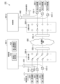
- FIG. 1 is a diagram illustrating an example of the configuration of an optical communication system according to a first embodiment.
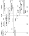
- 1 is a sequence diagram showing the flow of an optical path opening process (part 1) of the optical communication system according to the first embodiment.
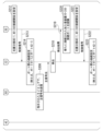
- FIG. FIG. 11 is a sequence diagram showing the flow of an optical path opening process (part 2) of the optical communication system in the first embodiment.
- FIG. 11 is a sequence diagram showing the flow of an optical path opening process (part 2) of the optical communication system in the first embodiment.
- FIG. 11 is a sequence diagram showing the flow of an optical path opening process (part 3) of the optical communication system in the first embodiment.
- FIG. 11 is a sequence diagram showing the flow of an optical path opening process (part 3) of the optical communication system in the first embodiment.
- FIG. 11 is a sequence diagram showing the flow of an optical path opening process (part 3) of the optical communication system in the first embodiment.
- FIG. 1 is a diagram illustrating an example of a configuration of an optical communication system according to a first modified example of the first embodiment.
- FIG. 11 is a diagram illustrating an example of the configuration of an optical communication system according to a second embodiment.
- FIG. 1 is a diagram for explaining a method for opening an optical path in a conventional optical communication system.
- FIG. 1 is a diagram for explaining a method for opening an optical path in a conventional optical communication system.
- FIG. 1 is a diagram illustrating an example of the configuration of a conventional optical communication system.
- the optical communication system 1 includes a plurality of subscriber devices 10 (e.g., subscriber devices 10-1 to 10-3), a plurality of subscriber devices 15 (e.g., subscriber devices 15-1 to 15-3), a plurality of first optical multiplexing/demultiplexing units 20 (e.g., first optical multiplexing/demultiplexing units 20-1 to 20-3), a second optical multiplexing/demultiplexing unit 30, a plurality of optical distribution units 40 (e.g., optical distribution units 40-1 to 40-2), a plurality of wavelength multiplexing/demultiplexing units 50 (e.g., wavelength multiplexing/demultiplexing units 50-1 to 50-2), a plurality of first optical multiplexing/demultiplexing units 60 (e.g., first optical multiplexing/demultiplexing units 60-1 to 60-3), a second optical multiplexing/demultiplexing unit 70, and a management
- the direction from the subscriber devices 10, 15 toward the management control device 80 is referred to as the upstream direction
- the direction from the management control device 80 toward the subscriber devices 10, 15 is referred to as the downstream direction.
- the numbers of subscriber devices 10, 15, first optical multiplexing/demultiplexing units 20, 60, second optical multiplexing/demultiplexing units 30, 70, optical distribution units 40, and wavelength multiplexing/demultiplexing units 50 included in the optical communication system 1 are not limited to the numbers shown in FIG. 1.
- optical transmission paths between the subscriber device 10 and the first optical multiplexing/demultiplexing unit 20, between the first optical multiplexing/demultiplexing unit 20 and the second optical multiplexing/demultiplexing unit 30, between the second optical multiplexing/demultiplexing units 30, 70 and the management control device 80, between the first optical multiplexing/demultiplexing unit 20 and the optical distribution unit 40-1, between the optical distribution unit 40-1 and the wavelength multiplexing/demultiplexing unit 50-1, between the wavelength multiplexing/demultiplexing unit 50-1 and the wavelength multiplexing/demultiplexing unit 50-2, between the wavelength multiplexing/demultiplexing unit 50-2 and the optical distribution unit 40-2, between the optical distribution unit 40-2 and the first optical multiplexing/demultiplexing unit 60, between the first optical multiplexing/demultiplexing unit 60 and the subscriber device 15, and between the first optical multiplexing/demultiplexing unit 60 and the second optical multiplexing/demultiplexing unit 70.
- the optical transmission path is, for example,
- the subscriber device 10 is equipped with an optical transceiver.
- the optical transceiver is, for example, a coherent transceiver.
- the subscriber device 10 transmits and receives optical signals such as main signals and control signals using the optical transceiver.
- the subscriber device 10 before the optical path is opened transmits light of a wavelength that reaches the optical distribution unit 40-1 in response to instructions from the management control device 80.
- the subscriber device 10 before the optical path is opened transmits light of a wavelength that reaches the optical distribution unit 40-1 after receiving, for example, control signal light from the management control device 80 instructing the output of the main signal light.
- the wavelength used here is notified to the subscriber device 10 before the optical path is opened in response to the exchange of information required for registration, authentication, and opening of the optical path between the management control device 80 and the subscriber device 10 before the optical path is opened.
- the information required to open an optical path includes, for example, information on the wavelengths used for transmission and reception, and information on the subscriber device 15 that is the target of communication.
- the light with a wavelength that reaches the optical distribution unit 40-1 is light within the wavelength range that is transmitted from the port on the subscriber device 10 side to the port on the optical distribution unit 40-1 side among the input/output ports of the first optical multiplexing/demultiplexing unit 20.
- the subscriber device 10 outputs the upstream control signal light to the management control device 80 as an optical signal with a wavelength different from that of the main signal light.
- the main signal light is light with a wavelength that reaches the optical distribution unit 40-1.
- the wavelength of the upstream control signal light transmitted by the subscriber device 10 is within the wavelength range that is transmitted from the port on the subscriber device 10 side to the port on the second optical distribution unit 30 side among the input/output ports of the first optical multiplexing/demultiplexing unit 20. Note that the wavelengths of the upstream control signal light transmitted by each subscriber device 10 may all be the same.
- the subscriber device 10 is, for example, an ONU (Optical Network Unit) installed in a subscriber's premises.
- the subscriber device 10-1 is a subscriber device that is newly connected to the optical distribution unit 40-1
- the subscriber device that is newly connected to the optical distribution unit 40 will be described as a new subscriber device.
- the subscriber device 15 is a device that communicates with the subscriber device 10.
- the subscriber device 15 is equipped with an optical transceiver.
- the subscriber device 15 transmits and receives optical signals such as main signals and control signals using the optical transceiver.
- the subscriber device 15 also performs the same processing as the subscriber device 10 before the optical path is opened.
- the subscriber device 15 receives downstream control signal light transmitted from the management control device 80 and main signal light transmitted over the optical transmission path 86.
- the subscriber device 15 is, for example, an ONU installed in a subscriber's premises.
- the first optical multiplexing/demultiplexing unit 20 is provided between the subscriber device 10 and the optical distribution unit 40-1.
- the first optical multiplexing/demultiplexing unit 20 branches and outputs the upstream control signal light and main signal light transmitted at different wavelengths from each subscriber device 10.
- the branching performed by the first optical multiplexing/demultiplexing unit 20 includes a case where the upstream control signal light and the main signal light are separated, and a case where the upstream control signal light and the main signal light are branched at a predetermined ratio.
- the first optical multiplexing/demultiplexing unit 20 When separating the upstream control signal light and the main signal light, the first optical multiplexing/demultiplexing unit 20 separates the upstream control signal light and the main signal light by wavelength, outputs the separated upstream control signal light to the second optical multiplexing/demultiplexing unit 30, and outputs the separated main signal light to the optical distribution unit 40-1.
- the first optical multiplexer/demultiplexer 20 splits both the upstream control signal light and the main signal light at a predetermined ratio and outputs them to the second optical multiplexer/demultiplexer 30 and the optical distributor 40-1.
- the first optical multiplexer/demultiplexer 20 in the first embodiment is, for example, an optical multiplexer/demultiplexer with wavelength selectivity (for example, a wavelength filter).
- the second optical multiplexing/demultiplexing unit 30 is provided between the first optical multiplexing/demultiplexing unit 20 and the control unit 81-1.
- the second optical multiplexing/demultiplexing unit 30 multiplexes the upstream control signal light transferred from each first optical multiplexing/demultiplexing unit 20 and outputs it to the control unit 81-1.
- the second optical multiplexing/demultiplexing unit 30 is, for example, an optical coupler.
- the optical distribution unit 40-1 has P (P is an integer of 2 or more) ports 41-1, Q (Q is an integer of 2 or more) ports 42-1, and an optical detection unit 43-1.
- the optical distribution unit 40-2 has a similar configuration to the optical distribution unit 40-1, so the configuration of the optical distribution unit 40-1 will be used as an example to explain the configuration.
- An optical signal input to a port of the optical distribution unit 40 is output from another port.
- an optical signal input to port 41-1 of the optical distribution unit 40 is output from port 42-1.
- the optical distribution unit 40 in the first embodiment is an FXC (Fiber Cross Connect) that outputs light input from each port to a port that is set as a connection port for that port, regardless of wavelength.
- FXC Fiber Cross Connect
- optical distribution unit 40 in the first embodiment for example, a spatial optical switch using a MEMS (Micro Electro Mechanical Systems) or a piezoelectric actuator is used.
- Port 41-1 is an embodiment of the first port
- port 42-1 is an embodiment of the second port.
- the optical detection unit 43-1 detects an optical signal input to port 41-1. When the optical detection unit 43-1 detects an optical signal, it notifies the management control device 80 of the detection result, including the port where the optical signal was detected.
- the notification from the optical detection unit 43-1 to the management control device 80 may be sent via an electrical line connecting the management control device 80 and the optical distribution unit 40-1. The notification sent from the optical detection unit 43-1 allows the management control device 80 to recognize the input of light to the port to which a new subscriber device 10 is connected.
- the wavelength multiplexing/demultiplexing unit 50 multiplexes or demultiplexes the input optical signals according to their wavelengths.
- the wavelength multiplexing/demultiplexing unit 50-1 multiplexes optical signals of multiple wavelengths output from the optical distribution unit 40-1 to generate multiplexed signal light.
- the wavelength multiplexing/demultiplexing unit 50-1 outputs the generated multiplexed signal light to the optical transmission path.
- the wavelength multiplexing/demultiplexing unit 50-2 demultiplexes the multiplexed signal light input via the optical transmission path by wavelength and outputs it.
- the wavelength multiplexing/demultiplexing unit 50 is, for example, an AWG (Arrayed Waveguide Grating) or a WSS (Wavelength Selective Switch).
- the first optical multiplexer/demultiplexer 60 is provided between the subscriber device 15 and the optical distribution unit 40-2.
- the first optical multiplexer/demultiplexer 60 wavelength-multiplexes the main signal light transmitted through the optical transmission path and the downstream control signal light output from the second optical multiplexer/demultiplexer 70, and outputs the multiplexed signal to the subscriber device 15.
- the first optical multiplexer/demultiplexer 60 is a wavelength-selective optical multiplexer/demultiplexer (e.g., a wavelength filter).
- the second optical multiplexer/demultiplexer 70 is provided between the first optical multiplexer/demultiplexer 60 and the control unit 81-2.
- the second optical multiplexer/demultiplexer 70 branches the downstream control signal light output from the control unit 81-2 and outputs it to each first optical multiplexer/demultiplexer 60.
- the second optical multiplexer/demultiplexer 70 is, for example, an optical coupler.
- the management control device 80 controls at least the subscriber devices 10 and 15 and the optical distribution unit 40.
- the control of the subscriber devices 10 and 15 includes, for example, control of the transmission timing of the main signal light, allocation of emission wavelengths to the subscriber devices 10 and 15, and instructions to stop light and change wavelengths.
- the control of the optical distribution unit 40 includes, for example, switching of connections between ports of the optical distribution unit 40.
- the management control device 80 includes multiple control units 81 (for example, control units 81-1 to 81-2). Each control unit 81 controls each optical distribution unit 40 and the subscriber devices 10 and 15 accommodated in each optical distribution unit 40.
- the control unit 81-1 controls the optical distribution unit 40-1 and the subscriber device 10 accommodated in the optical distribution unit 40-1.
- the control unit 81-2 controls the optical distribution unit 40-2 and the subscriber device 15 accommodated in the optical distribution unit 40-2.
- the control unit 81-1 includes an optical distribution control unit 82-1 and a subscriber device management control unit 83-1.
- the control unit 81-2 has a similar configuration to the control unit 81-1.
- the control units 81-1 and 81-2 perform similar processing except for the objects they control, so the optical distribution control unit 82-1 and the subscriber device management control unit 83-1 will be used as examples for explanation.
- the optical distribution control unit 82-1 sets the route of the optical path by setting and switching the connection between the ports of the optical distribution unit 40.
- the optical distribution control unit 82-1 controls the connection between the ports of the optical distribution unit 40 so as to connect, for example, the port 41-1 where the main signal light is detected by the optical detection unit 43-1 to the port 42-1 to which the subscriber device 15 that will be the communication partner of the new subscriber device is connected.
- the subscriber device management control unit 83-1 transmits to the new subscriber device at least a control signal light that instructs the new subscriber device to output a main signal light. After transmitting the control signal light, the subscriber device management control unit 83-1 identifies which port of the optical distribution unit 40 the new subscriber device is connected to based on the detection result transmitted from the optical distribution unit 40.
- the subscriber device management control unit 83-1 prevents subscriber devices 10 other than the new subscriber device, which is the destination of the control signal light, from starting to transmit the main signal light for a predetermined period of time after transmitting the control signal light, so that only the main signal light transmitted from the new subscriber device, which is the destination of the control signal light, is newly detected in the optical distribution unit 40.
- the detection result from the optical distribution unit 40 obtained in this manner is associated with the new subscriber device, which is the destination of the control signal light, to identify which port of the optical distribution unit 40 the new subscriber device is connected to.
- the subscriber device management control unit 83-1 recognizes the port where new optical detection is performed by the optical detection unit 43 as the port to which the new subscriber device will be connected.
- the subscriber device management control unit 83-1 will not transmit a control signal light to instruct the other new subscriber devices to output a main signal light until it has completed associating one new subscriber device with the port 41-1 of the optical distribution unit 40.
- This makes it possible to control multiple new subscriber devices so that they do not transmit main signal light at the same time.
- the optical distribution unit 40 newly detects only the main signal light transmitted from the new subscriber device that is the destination of the control signal light. By associating the detection result from the optical distribution unit 40 obtained in this way with the new subscriber device that is the destination of the control signal light, it is possible to identify which port of the optical distribution unit 40 the new subscriber device is connected to.
- the subscriber device management control unit 83-1 opens an optical path by switching the connection relationship of the optical distribution unit 40 so that the identified port and the port to which the subscriber device 15 to be communicated with is connected can communicate with each other.
- the subscriber device management control unit 83-1 measures the round trip time (RTT) between the new subscriber device and the subscriber device management control unit 83-1 by sending and receiving control signal light between the new subscriber device and the subscriber device management control unit 83-1.
- RTT round trip time
- the subscriber device management control unit 83-1 performs photoelectric conversion on the upstream control signal light transmitted from the subscriber device 10, and then uses an identifier contained in the upstream control signal to recognize the subscriber device 10 that is the sender of the received upstream control signal light. Examples of identifiers include an ID assigned to the subscriber device 10 by the subscriber device management control unit 83-1, and the MAC (Media Access Control) address of the subscriber device 10.
- upstream control signal light When upstream control signal light is transmitted from multiple subscriber devices 10 at the same time, the upstream control signal light may collide. Therefore, to enable the subscriber device management control unit 83-1 to exchange control signal light with multiple subscriber devices 10, for example, a PON (Passive Optical Network) method can be applied.
- the subscriber device 10 outputs upstream control signal light including a control signal only during the time period permitted by the subscriber device management control unit 83-1, and stops outputting the upstream control signal light during other time periods.
- the upstream control signal light is a burst signal light.
- the subscriber device management control unit 83-1 recognizes the RTT between each subscriber device 10 and the subscriber device management control unit 83-1. Therefore, the subscriber device management control unit 83-1 refers to the RTT value and gives each subscriber device 10 permission to transmit the upstream control signal light so that the upstream control signal light from the subscriber device 10, which is a burst signal light, does not arrive at the subscriber device management control unit 83-1 in the same time period as the upstream control signal light from another subscriber device 10.
- the subscriber device management control unit 83-1 exchanges information required for registration, authentication, and opening of an optical path with a new subscriber device (e.g., subscriber device 10-1) via the first optical multiplexing/demultiplexing unit 20 and the second optical multiplexing/demultiplexing unit 30. Furthermore, the subscriber device management control unit 83-1 exchanges control information with the subscriber device 10 after the optical path is opened via the first optical multiplexing/demultiplexing unit 20 and the second optical multiplexing/demultiplexing unit 30.
- a new subscriber device e.g., subscriber device 10-1
- the subscriber device management control unit 83-1 exchanges control information with the subscriber device 10 after the optical path is opened via the first optical multiplexing/demultiplexing unit 20 and the second optical multiplexing/demultiplexing unit 30.
- the control unit 81-2 transmits downstream control signal light to the subscriber device 15.
- the wavelength of the downstream control signal light transmitted by the control unit 81-2 is within the wavelength range that is transmitted from the port on the second optical multiplexing/demultiplexing unit 70 side to the port on the subscriber device 15 side among the input/output ports of the first optical multiplexing/demultiplexing unit 60.
- the downstream control signal light is a signal light in which downstream control signals addressed to each subscriber device 15 are time-multiplexed. After photoelectrically converting the downstream control signal light, the subscriber device 15 selectively receives a downstream control signal addressed to itself from the time-multiplexed downstream control signals using an identifier included in the downstream control signal.
- Examples of the identifier include an ID assigned to the subscriber device 15 by the subscriber device management control unit 83-2 provided in the control unit 81-2, and the MAC address of the subscriber device 15.
- the functions of the control unit 81 may be realized by one or more processors executing a program.
- FIG. 2 is a sequence diagram showing the flow of an optical path opening process (part 1) in the optical communication system 1 in the first embodiment.
- the explanation will be given assuming that the new subscriber device is the subscriber device 10-1.
- step S101 The subscriber device management control unit 83-1 provided in the control unit 81-1 recognizes the subscriber device 10-1 that has been newly connected to the optical distribution unit 40-1 (step S102).
- the subscriber device management control unit 83-1 exchanges information necessary to open an optical path with the subscriber device 10-1 (step S103). While exchanging information necessary to open an optical path, the subscriber device management control unit 83-1 measures the RTT between the subscriber device management control unit 83-1 and the subscriber device 10-1. The subscriber device management control unit 83-1 stores the measured RTT value in association with the identifier of the subscriber device 10-1.
- the subscriber device management control unit 83-1 generates a control signal that instructs the output of the main signal light (step S104).
- the subscriber device management control unit 83-1 converts the generated control signal into an optical signal and transmits it to the subscriber device 10-1 as a downstream control signal light (step S105).
- the downstream control signal light transmitted from the subscriber device management control unit 83-1 is input to the second optical multiplexing/demultiplexing unit 30.
- the second optical multiplexing/demultiplexing unit 30 branches and outputs the input downstream control signal light.
- the downstream control signal light branched by the second optical multiplexing/demultiplexing unit 30 is input to each first optical multiplexing/demultiplexing unit 20.
- Each first optical multiplexing/demultiplexing unit 20 outputs the input downstream control signal light to the connected subscriber device 10 via the optical transmission path 85.
- each subscriber device 10 receives the downstream control signal light that instructs the output of the main signal light transmitted from the subscriber device management control unit 83-1.
- the subscriber device 10-1 transmits the main signal light of the wavelength that reaches the optical distribution unit 40-1 to the optical transmission path 85-1 (step S106). For example, immediately after receiving the downstream control signal light or after a predetermined period of time has elapsed since receiving it, the subscriber device 10-1 transmits the main signal light of the wavelength that reaches the optical distribution unit 40-1 to the optical transmission path 85-1.
- the main signal light transmitted from the subscriber device 10-1 is input to the first optical multiplexing and demultiplexing unit 20-1 via the optical transmission path 85-1.
- the first optical multiplexer/demultiplexer 20-1 outputs the input main signal light to the optical distribution unit 40-1.
- the wavelength of the main signal light transmitted by the subscriber device 10-1 is within the wavelength range that is transmitted from the port on the subscriber device 10 side to the port on the optical distribution unit 40-1 side among the input/output ports of the first optical multiplexer/demultiplexer 20, so the main signal light input to the first optical multiplexer/demultiplexer 20-1 is output to the optical distribution unit 40-1.
- the optical detection unit 43-1 of the optical distribution unit 40-1 detects the main signal light output from the first optical multiplexer/demultiplexer 20-1 (step S107).
- the optical detection unit 43-1 detects the main signal light output from the first optical multiplexer/demultiplexer 20-1 at port 41-1-1.
- the optical detection unit 43-1 transmits the detection result indicating that light has been detected at port 41-1-1 to the control unit 81-1 (step S108).
- the subscriber device management control unit 83-1 included in the control unit 81-1 acquires the detection result sent from the optical detection unit 43-1. Based on the acquired detection result, the subscriber device management control unit 83-1 recognizes the port to which the subscriber device 10-1 newly connected to the optical distribution unit 40-1 is connected (step S109). Specifically, the subscriber device management control unit 83-1 associates the port included in the detection result (e.g., port 41-1-1) with the subscriber device 10-1 to which the downstream control signal light is to be sent. As a result, the subscriber device management control unit 83-1 recognizes that the subscriber device 10-1 newly connected to the optical distribution unit 40-1 is connected to the port included in the detection result (e.g., port 41-1-1).
- the optical distribution control units 82-1 and 82-2 set the connection relationship between the ports of the optical distribution units 40-1 and 40-2 based on the recognized port and information on the subscriber device 15 (e.g., subscriber device 15-1) with which the subscriber device 10-1 communicates (step S110). Specifically, the optical distribution control unit 82-1 sets the connection relationship of the optical distribution unit 40-1 so as to connect the port 41-1-1 to which the subscriber device 10-1 is connected and the port 42-1-2 connected to the optical distribution unit 40-2 to which the subscriber device 15-1 is connected. The optical distribution control unit 82-1 generates a control signal for connecting the port 41-1-1 and the port 42-1-2. The optical distribution control unit 82-1 transmits the generated control signal to the optical distribution unit 40-1 (step S111).
- the optical distribution control unit 82-1 sets the connection relationship between the ports of the optical distribution units 40-1 and 40-2 based on the recognized port and information on the subscriber device 15 (e.g., subscriber device 15-1) with which the subscriber device 10-1 communicates (step S110). Specifically
- the optical distribution control unit included in the control unit 81-2 sets the connection relationship of the optical distribution unit 40-2 so as to connect the port to which the subscriber device 15-1 is connected and the port connected to the optical distribution unit 40-1 to which the subscriber device 10-1 is connected.
- the optical distribution control unit included in the control unit 81-2 generates a control signal for connecting the port to which the subscriber device 15-1 is connected and the port connected to the optical distribution unit 40-1 to which the subscriber device 10-1 is connected.
- the optical distribution control unit included in the control unit 81-2 transmits the generated control signal to the optical distribution unit 40-2.
- the optical distribution units 40-1 and 40-2 set the connection relationship between the ports based on the control signal sent from the management control device 80 (step S112). This opens an optical path between the subscriber device 10-1 and the subscriber device 15-1. As a result, communication becomes possible between the subscriber device 10-1 and the subscriber device 15-1.
- the subscriber device management control unit 83-1 may refer to the RTT value of the subscriber device 10 for which an optical path has already been opened and give transmission permission to each of the subscriber devices 10 for which an optical path has already been opened so that the main signal light from the other subscriber devices 10 is not transmitted during the period during which the main signal light transmitted by the subscriber device 10-1 in response to the downstream control signal light can reach the optical distribution unit 40-1.
- the period during which the main signal light transmitted by the subscriber device 10-1 in response to the downstream control signal light can reach the optical distribution unit 40-1 is set in advance.
- the subscriber device management control unit 83-1 recognizes the port where the light is detected by the light detection unit 43 while the light detection is stopped at the port of the optical distribution unit 40 to which the subscriber device 10 for which an optical path has already been opened is connected as the port to which the new subscriber device is to be connected. This makes it possible to prevent optical signals other than the main signal light transmitted from the subscriber device 10-1 from being input to the optical distribution unit 40-1. As a result, it is possible to prevent the subscriber device management control unit 83-1 from making an incorrect association.
- FIG. 3 and Fig. 4 are sequence diagrams showing the flow of the optical path opening process (part 2) of the optical communication system 1 in the first embodiment. Note that in Fig. 3 and Fig. 4, the explanation will be given assuming that the new subscriber devices are subscriber devices 10-1 and 10-2.
- subscriber device 10-1 Assume that a first user connects subscriber device 10-1 to the optical distribution unit 40-1 via the optical transmission path 85-1. As a result, subscriber device 10-1 is connected to the optical distribution unit 40-1 via the optical transmission path 85-1 (step S201). As a result, subscriber device 10-2 is connected to the optical distribution unit 40-1 via the optical transmission path 85-2 (step S202).
- the subscriber device management control unit 83-1 included in the control unit 81-1 recognizes the subscriber devices 10-1 and 10-2 that have been newly connected to the optical distribution unit 40-1 (step S203).
- the subscriber device management control unit 83-1 exchanges information necessary for opening an optical path with the subscriber device 10-1 (step S204). While exchanging information necessary for opening an optical path, the subscriber device management control unit 83-1 measures the RTT between the subscriber device management control unit 83-1 and the subscriber device 10-1.
- the subscriber device management control unit 83-1 stores the measured RTT value in association with the identifier of the subscriber device 10-1.
- the subscriber device management control unit 83-1 exchanges information necessary for opening an optical path with the subscriber device 10-2 (step S205). While exchanging information necessary for opening an optical path, the subscriber device management control unit 83-1 measures the RTT between the subscriber device management control unit 83-1 and the subscriber device 10-2. The subscriber device management control unit 83-1 stores the measured RTT value in association with the identifier of the subscriber device 10-2.
- the subscriber device management control unit 83-1 generates a control signal that instructs the output of the main signal light (step S206).
- the subscriber device management control unit 83-1 converts the generated control signal into an optical signal and transmits it to the subscriber device 10-1 as a downstream control signal light (step S207).
- the downstream control signal light transmitted from the subscriber device management control unit 83-1 is input to the second optical multiplexing/demultiplexing unit 30.
- the second optical multiplexing/demultiplexing unit 30 branches and outputs the input downstream control signal light.
- the downstream control signal light branched by the second optical multiplexing/demultiplexing unit 30 is input to each first optical multiplexing/demultiplexing unit 20.
- Each first optical multiplexing/demultiplexing unit 20 outputs the input downstream control signal light to the connected subscriber device 10 via the optical transmission path 85.
- each subscriber device 10 receives the downstream control signal light transmitted from the subscriber device management control unit 83-1.
- the subscriber device 10-1 In response to receiving the downstream control signal light transmitted from the subscriber device management and control unit 83-1, the subscriber device 10-1 transmits the main signal light of the wavelength that reaches the optical distribution unit 40-1 to the optical transmission path 85-1 (step S208).
- the downstream control signal light transmitted from the subscriber device management and control unit 83-1 is also received by the subscriber device 10-2.
- the subscriber device 10-2 discards the control signal included in the received downstream control signal light.
- the subscriber device 10-1 transmits the main signal light of a wavelength that reaches the optical distribution unit 40-1 to the optical transmission path 85-1.
- the main signal light transmitted from the subscriber device 10-1 is input to the first optical multiplexing/demultiplexing unit 20-1 via the optical transmission path 85-1.
- the first optical multiplexer/demultiplexer 20-1 outputs the input main signal light to the optical distribution unit 40-1.
- the wavelength of the main signal light transmitted by the subscriber device 10-1 is within the wavelength range that is transmitted from the port on the subscriber device 10 side to the port on the optical distribution unit 40-1 side among the input/output ports of the first optical multiplexer/demultiplexer 20, so the main signal light input to the first optical multiplexer/demultiplexer 20-1 is output to the optical distribution unit 40-1.
- the optical detection unit 43-1 of the optical distribution unit 40-1 detects the main signal light output from the first optical multiplexer/demultiplexer 20-1 (step S209).
- the optical detection unit 43-1 detects the main signal light output from the first optical multiplexer/demultiplexer 20-1 at port 41-1-1.
- the optical detection unit 43-1 transmits the detection result indicating that light has been detected at port 41-1-1 to the control unit 81-1 (step S210).
- the subscriber device management control unit 83-1 included in the control unit 81-1 acquires the detection result sent from the optical detection unit 43-1. Based on the acquired detection result, the subscriber device management control unit 83-1 recognizes the port to which the subscriber device 10-1 newly connected to the optical distribution unit 40-1 is connected (step S211). Specifically, the subscriber device management control unit 83-1 associates the port included in the detection result (e.g., port 41-1-1) with the subscriber device 10-1 to which the downstream control signal light is to be sent. As a result, the subscriber device management control unit 83-1 recognizes that the subscriber device 10-1 newly connected to the optical distribution unit 40-1 is connected to the port included in the detection result (e.g., port 41-1-1).
- the optical distribution control units 82-1 and 82-2 set the connection relationship between the ports of the optical distribution units 40-1 and 40-2 based on the recognized port and information on the subscriber device 15 (e.g., subscriber device 15-1) with which the subscriber device 10-1 communicates (step S212). Specifically, the optical distribution control unit 82-1 sets the connection relationship of the optical distribution unit 40-1 so as to connect the port 41-1-1 to which the subscriber device 10-1 is connected and the port 42-1-2 to which the subscriber device 15-1 is connected. The optical distribution control unit 82-1 generates a control signal for connecting the port 41-1-1 and the port 42-1-2. The optical distribution control unit 82-1 transmits the generated control signal to the optical distribution unit 40-1 (step S213).
- the optical distribution control unit included in the control unit 81-2 sets the connection relationship of the optical distribution unit 40-2 so as to connect the port to which the subscriber device 15-1 is connected and the port connected to the optical distribution unit 40-1 to which the subscriber device 10-1 is connected.
- the optical distribution control unit included in the control unit 81-2 generates a control signal for connecting the port to which the subscriber device 15-1 is connected and the port connected to the optical distribution unit 40-1 to which the subscriber device 10-1 is connected.
- the optical distribution control unit included in the control unit 81-2 transmits the generated control signal to the optical distribution unit 40-2.
- the optical distribution units 40-1 and 40-2 set the connection relationship between the ports based on the control signal sent from the management control device 80 (step S214). This opens an optical path between the subscriber device 10-1 and the subscriber device 15-1. As a result, communication becomes possible between the subscriber device 10-1 and the subscriber device 15-1.
- the subscriber device management control unit 83-1 again generates a downstream control signal that instructs the output of the main signal light (step S215).
- the subscriber device management control unit 83-1 converts the generated downstream control signal into an optical signal and transmits it to the subscriber device 10-2 as a downstream control signal light (step S216).
- the downstream control signal light transmitted from the subscriber device management control unit 83-1 is input to the second optical multiplexing/demultiplexing unit 30.
- the second optical multiplexing/demultiplexing unit 30 branches and outputs the input downstream control signal light.
- the downstream control signal light branched by the second optical multiplexing/demultiplexing unit 30 is input to each first optical multiplexing/demultiplexing unit 20.
- Each first optical multiplexing/demultiplexing unit 20 outputs the input downstream control signal light to the connected subscriber device 10 via the optical transmission path 85.
- each subscriber device 10 receives the downstream control signal light transmitted from the subscriber device management control unit 83-1.
- the subscriber device 10-2 In response to receiving the downstream control signal light transmitted from the subscriber device management and control unit 83-1, the subscriber device 10-2 transmits the main signal light of the wavelength that reaches the optical distribution unit 40-1 to the optical transmission path 85-2 (step S217).
- the subscriber device 10-1 also receives the downstream control signal light transmitted from the subscriber device management and control unit 83-1. However, because the destination of the control signal is not the subscriber device 10-1, the subscriber device 10-1 discards the control signal included in the received control signal light.
- the subscriber device 10-2 transmits the main signal light of a wavelength that reaches the optical distribution unit 40-1 to the optical transmission path 85-2.
- the main signal light transmitted from the subscriber device 10-2 is input to the first optical multiplexing/demultiplexing unit 20-2 via the optical transmission path 85-2.
- the first optical multiplexer/demultiplexer 20-2 outputs the input main signal light to the optical distribution unit 40-1.
- the wavelength of the main signal light transmitted by the subscriber device 10-2 is within the wavelength range that is transmitted from the port on the subscriber device 10 side to the port on the optical distribution unit 40-1 side among the input/output ports of the first optical multiplexer/demultiplexer 20, so the main signal light input to the first optical multiplexer/demultiplexer 20-2 is output to the optical distribution unit 40-1.
- the optical detection unit 43-1 of the optical distribution unit 40-1 detects the main signal light output from the first optical multiplexer/demultiplexer 20-2 (step S218).
- the optical detection unit 43-1 detects the main signal light output from the first optical multiplexer/demultiplexer 20-2 at port 41-1-2.
- the optical detection unit 43-1 transmits the detection result indicating that light has been detected at port 41-1-2 to the control unit 81-1 (step S219).
- the subscriber device management control unit 83-1 included in the control unit 81-1 acquires the detection result sent from the optical detection unit 43-1. Based on the acquired detection result, the subscriber device management control unit 83-1 recognizes the port to which the subscriber device 10-2 newly connected to the optical distribution unit 40-1 is connected (step S220). Specifically, the subscriber device management control unit 83-1 associates the port included in the detection result (e.g., port 41-1-2) with the subscriber device 10-2 to which the downstream control signal light is to be sent. As a result, the subscriber device management control unit 83-1 recognizes that the subscriber device 10-2 newly connected to the optical distribution unit 40-1 is connected to the port included in the detection result (e.g., port 41-1-2).
- the optical distribution control units 82-1 and 82-2 set the connection relationship between the ports of the optical distribution units 40-1 and 40-2 based on the recognized port and information on the subscriber device 15 (e.g., subscriber device 15-2) with which the subscriber device 10-2 communicates (step S221). Specifically, the optical distribution control unit 82-1 sets the connection relationship of the optical distribution unit 40-1 so as to connect the port 41-1-2 to which the subscriber device 10-2 is connected and the port 42-1-3 connected to the optical distribution unit 40-2 to which the subscriber device 15-2 is connected. The optical distribution control unit 82-1 generates a control signal for connecting the port 41-1-2 and the port 42-1-3. The optical distribution control unit 82-1 transmits the generated control signal to the optical distribution unit 40-1 (step S222).
- the optical distribution control unit 82-1 sets the connection relationship between the ports of the optical distribution units 40-1 and 40-2 based on the recognized port and information on the subscriber device 15 (e.g., subscriber device 15-2) with which the subscriber device 10-2 communicates (step S221). Specifically
- the optical distribution control unit included in the control unit 81-2 sets the connection relationship of the optical distribution unit 40-2 so as to connect the port to which the subscriber device 15-2 is connected and the port connected to the optical distribution unit 40-1 to which the subscriber device 10-2 is connected.
- the optical distribution control unit included in the control unit 81-2 generates a control signal for connecting the port to which the subscriber device 15-2 is connected and the port connected to the optical distribution unit 40-1 to which the subscriber device 10-2 is connected.
- the optical distribution control unit included in the control unit 81-2 transmits the generated control signal to the optical distribution unit 40-2.
- the optical distribution units 40-1 and 40-2 set the connection relationship between the ports based on the control signal sent from the management control device 80 (step S223). This opens an optical path between the subscriber device 10-2 and the subscriber device 15-2. As a result, communication becomes possible between the subscriber device 10-2 and the subscriber device 15-2.
- the flow is described in which the subscriber device management control unit 83-1 transmits downstream control signal light to other new subscriber devices after an optical path between one new subscriber device and the communication partner is opened.
- the subscriber device management control unit 83-1 may execute the process of step S215 after the process of step S211 is completed. That is, the subscriber device management control unit 83-1 may transmit a downstream control signal light to instruct the subscriber device 10-2 to output at least the main signal light after recognizing the port to which the subscriber device 10-1 newly connected to the optical distribution unit 40-1 is connected.
- the subscriber device management control unit 83-1 instructs the optical distribution control unit 82-1 to control the connection between the ports of the optical distribution unit 40 after recognizing the ports to which each of the multiple new subscriber devices is connected.
- the subscriber device management control unit 83-1 may sequentially set the port-to-port connection of the optical distribution unit 40 for each optical path.
- the subscriber device management control unit 83-1 may refer to the RTT value of the subscriber device 10 for which an optical path has been opened and give transmission permission to each subscriber device 10 for which an optical path has been opened, so that the main signal light from other subscriber devices 10 is not transmitted during the period in which the main signal light transmitted by the subscriber device 10-1 or 10-2 in response to the downstream control signal light can reach the optical distribution unit 40-1.
- This makes it possible to prevent optical signals other than the main signal light transmitted from the subscriber device 10-1 or 10-2 from being input to the optical distribution unit 40-1. As a result, it is possible to prevent incorrect association in the subscriber device management control unit 83-1.
- Figures 5 and 6 are sequence diagrams showing the flow of the optical path opening process (part 3) in the optical communication system 1 in the first embodiment. Note that in Figures 5 and 6, the explanation will be given assuming that the new subscriber devices are subscriber devices 10-1 and 10-2. In Figures 5 and 6, the same processes as in Figures 3 and 4 are denoted by the same reference numerals as in Figures 3 and 4, and explanations will be omitted.
- the subscriber device management and control unit 83-1 When the processing from step S201 to step S205 is completed, the subscriber device management and control unit 83-1 generates a control signal including an instruction to output the main signal light and information indicating the timing of transmission of the main signal light by the subscriber device 10-1 (step S301).
- the subscriber device management and control unit 83-1 converts the generated control signal into an optical signal and transmits it to the subscriber device 10-1 as a downstream control signal light (step S302).
- the downstream control signal light transmitted from the subscriber device management and control unit 83-1 is input to the second optical multiplexing and demultiplexing unit 30.
- the second optical multiplexing and demultiplexing unit 30 branches and outputs the input downstream control signal light.
- the downstream control signal light branched by the second optical multiplexing and demultiplexing unit 30 is input to each first optical multiplexing and demultiplexing unit 20.
- Each first optical multiplexer/demultiplexer 20 outputs the input downstream control signal light to the connected subscriber device 10 via the optical transmission path 85.
- each subscriber device 10 receives the downstream control signal light transmitted from the subscriber device management control unit 83-1.
- Subscriber device 10-1 waits until the transmission timing indicated by the control signal included in the downstream control signal light transmitted from the subscriber device management control unit 83-1.
- subscriber device 10-2 also receives the downstream control signal light transmitted from the subscriber device management control unit 83-1 in the processing of step S302. However, because the destination of the downstream control signal light is not subscriber device 10-2, subscriber device 10-2 discards the control signal included in the received downstream control signal light.
- the subscriber device management and control unit 83-1 After processing in step S302, the subscriber device management and control unit 83-1 generates a control signal including an instruction to output the main signal light and information indicating the timing of transmission of the main signal light by the subscriber device 10-2 (step S303).
- the subscriber device management and control unit 83-1 determines the transmission timing so that the timing of transmission of the main signal light by the subscriber device 10-1 does not overlap with the timing of transmission of the main signal light by the subscriber device 10-2.
- the subscriber device management and control unit 83-1 determines the transmission timing of the main signal light by the subscriber device 10-2 so that the period during which the main signal light transmitted by the subscriber device 10-1 in response to the downstream control signal light can reach the optical distribution unit 40-1 does not overlap with the period during which the main signal light transmitted by the subscriber device 10-2 in response to the downstream control signal light can reach the optical distribution unit 40-1.
- the subscriber device management and control unit 83-1 converts the generated control signal into an optical signal and transmits it to the subscriber device 10-2 as downstream control signal light (step S304).
- the downstream control signal light transmitted from the subscriber device management and control unit 83-1 is input to the second optical multiplexing and demultiplexing unit 30.
- the second optical multiplexing and demultiplexing unit 30 branches and outputs the input downstream control signal light.
- the downstream control signal light branched by the second optical multiplexing and demultiplexing unit 30 is input to each first optical multiplexing and demultiplexing unit 20.
- Each first optical multiplexer/demultiplexer 20 outputs the input downstream control signal light to the connected subscriber device 10 via the optical transmission path 85.
- each subscriber device 10 receives the downstream control signal light transmitted from the subscriber device management control unit 83-1.
- Subscriber device 10-2 waits until the transmission timing indicated by the control signal included in the downstream control signal light transmitted from the subscriber device management control unit 83-1.
- subscriber device 10-1 also receives the downstream control signal light transmitted from the subscriber device management control unit 83-1 in the processing of step S304. However, because the destination of the downstream control signal light is not subscriber device 10-1, subscriber device 10-1 discards the control signal included in the received downstream control signal light.
- the subscriber device 10-1 transmits the main signal light of the wavelength that will reach the optical distribution unit 40-1 to the optical transmission path 85-1 (step S305).
- the main signal light transmitted from the subscriber device 10-1 is input to the first optical multiplexing/demultiplexing unit 20-1 via the optical transmission path 85-1.
- the first optical multiplexing/demultiplexing unit 20-1 outputs the input main signal light to the optical distribution unit 40-1.
- the main signal light input to the first optical multiplexing/demultiplexing unit 20-1 is output to the optical distribution unit 40-1. After that, the processing from step S209 to step S214 is executed.
- the subscriber device 10-2 transmits the main signal light of the wavelength that reaches the optical distribution unit 40-1 to the optical transmission path 85-2 (step S306).
- the main signal light transmitted from the subscriber device 10-2 is input to the first optical multiplexing/demultiplexing unit 20-2 via the optical transmission path 85-2.
- the first optical multiplexing/demultiplexing unit 20-2 outputs the input main signal light to the optical distribution unit 40-1.
- the main signal light input to the first optical multiplexing/demultiplexing unit 20-2 is output to the optical distribution unit 40-1.
- the subscriber device management control unit 83-1 may refer to the RTT value of the subscriber device 10 for which an optical path has been opened and give transmission permission to each subscriber device 10 for which an optical path has been opened, so that the main signal light from other subscriber devices 10 is not transmitted during the period in which the main signal light transmitted by the subscriber device 10-1 or 10-2 in response to the downstream control signal light can reach the optical distribution unit 40-1.
- This makes it possible to prevent optical signals other than the main signal light transmitted from the subscriber device 10-1 or 10-2 from being input to the optical distribution unit 40-1. As a result, it is possible to prevent incorrect association in the subscriber device management control unit 83-1.
- a first optical multiplexing/demultiplexing unit 20 that branches and outputs upstream control signal light and main signal light transmitted at different wavelengths from one or more newly connected subscriber devices 10, a subscriber device management and control unit 83 that transmits downstream control signal light to instruct the one or more newly connected subscriber devices 10 to output at least the main signal light in response to the upstream control signal light branched off by the first optical multiplexing/demultiplexing unit 20, and a subscriber device management and control unit 84 that transmits downstream control signal light to the one or more newly connected subscriber devices 10 in response to the downstream control signal light.
- the optical distribution unit 40 receives the main signal light transmitted from the optical fiber 10 and branched by the first optical multiplexer/demultiplexer 20 at port 41-1 and outputs it from port 42-1, an optical detection unit 43 detects the main signal light input to port 41-1 of the optical distribution unit 40, and an optical distribution control unit 82 controls the connection between the ports of the optical distribution unit 40 so as to connect the port 41-1 where the main signal light is detected by the optical detection unit 43 to the port 42-1 to which the subscriber device that will be the communication partner of the newly connected one or more subscriber devices 10 is connected.
- the subscriber device management control unit 83 transmits at least a downstream control signal light that instructs the output of the main signal light to the new subscriber device that is to transmit the main signal light. Then, the subscriber device management control unit 83 recognizes the port of the optical distribution unit 40 to which the new subscriber device that transmitted the main signal light in response to the downstream control signal light is connected, based on the detection result of the optical detection unit 43. This allows the control unit 81 to recognize which port of the optical distribution unit 40 the new subscriber device is connected to via the optical transmission path.
- the optical distribution control units 82-1 and 82-2 set the inter-port connection of the optical distribution units 40-1 and 40-2 so that the main signal light transmitted from the new subscriber device is transferred to the subscriber device 15 that is the communication partner. This makes it possible to open an optical path that connects the newly connected subscriber device and the communication partner subscriber device so that they can communicate in an optical communication system that has an optical multiplexing/demultiplexing unit between the optical distribution unit or control unit and the subscriber device.
- the optical communication system 1 when there are multiple new subscriber devices, as a first method, a downstream control signal light instructing the output of the main signal light is not transmitted to the other new subscriber devices until the correspondence between one of the multiple new subscriber devices and the port 41-1 of the optical distribution unit 40 is completed.
- the optical communication system 1 controls the transmission timing so that the main signal light is not transmitted from multiple new subscriber devices at the same timing. This makes it possible to narrow down the source of the main signal light detected by the optical detection unit 43 to one new subscriber device that is the destination of the downstream control signal light.
- the control unit 81 can recognize which port of the optical distribution unit 40 each of the multiple new subscriber devices is connected to via the optical transmission path.
- the second method is to notify each of the multiple new subscriber devices of the transmission timing of the main signal light.
- the optical communication system 1 controls the transmission timing so that the main signal light is not transmitted from multiple new subscriber devices at the same timing. This makes it possible to narrow down the source of the main signal light detected by the optical detection unit 43 to one new subscriber device that is the destination of the downstream control signal light.
- the control unit 81 can recognize which port of the optical distribution unit 40 each of the multiple new subscriber devices is connected to via the optical transmission path.
- the optical communication system 1a includes a plurality of subscriber devices 10 (e.g., subscriber devices 10-1 to 10-3), a plurality of subscriber devices 15 (e.g., subscriber devices 15-1 to 15-3), a plurality of first optical multiplexing/demultiplexing units 20 (e.g., first optical multiplexing/demultiplexing units 20-1 to 20-3), a second optical multiplexing/demultiplexing unit 30, a plurality of optical distribution units 40 (e.g., optical distribution units 40-1 to 40-2), a plurality of first optical multiplexing/demultiplexing units 60 (e.g., first optical multiplexing/demultiplexing units 60-1 to 60-3), a second optical multiplexing/demultiplexing unit 70, and a management control device 80.
- the optical communication system 1a is different in configuration from the optical communication system 1 in that it does not include
- the light distribution unit 40 has a function that allows a transmission path to be set for each wavelength.
- a WSS can be used as the light distribution unit 40. This makes it possible to eliminate the need for the wavelength multiplexing/demultiplexing unit 50.
- a multicast switch can be used as the light distribution unit 40.
- the configurations shown in Figures 1 and 7 the main signal light transmitted from subscriber device 10 to subscriber device 15 and the main signal light transmitted from subscriber device 15 to subscriber device 10 flow through the core wire of the same optical transmission line.
- the configuration may be such that there is a section in which the main signal light transmitted from subscriber device 10 to subscriber device 15 and the main signal light transmitted from subscriber device 15 to subscriber device 10 flow through different core wires of the optical transmission line.
- the subscriber device management control unit 83-1 sets the wavelengths of the signal lights of different directions to different wavelengths or gives transmission permission to the signal lights of different directions at different times to prevent deterioration of the reception characteristics of the signal light of the opposite direction due to reflection in the optical transmission line.
- the wavelengths of the signal lights of different directions can be the same wavelength.
- the first optical multiplexing/demultiplexing unit 20, the second optical multiplexing/demultiplexing unit 30, the optical distribution unit 40-1, the wavelength multiplexing/demultiplexing unit 50-1, and the control unit 81-1 may be configured as an optical communication device.
- the first optical multiplexing/demultiplexing unit 60, the second optical multiplexing/demultiplexing unit 70, the optical distribution unit 40-2, the wavelength multiplexing/demultiplexing unit 50-2, and the control unit 81-2 may be configured as an optical communication device.
- the first optical multiplexing/demultiplexing unit 20, the second optical multiplexing/demultiplexing unit 30, the optical distribution unit 40-1, and the control unit 81-1 may be configured as an optical communication device.
- the first optical multiplexing/demultiplexing unit 60, the second optical multiplexing/demultiplexing unit 70, the optical distribution unit 40-2, and the control unit 81-2 may be configured as an optical communication device.
- the optical distribution unit 40-1 under the control of the optical distribution control unit 82-1, switches the connection relationship between the ports so that each port 41-1 to which an optical path has not yet been opened is sequentially connected to the port 42-1-1 to which the optical detection unit 43-1 is connected.
- the optical detection unit 43-1 detects an optical signal output from the port 42-1-1 to which it is connected. When the optical detection unit 43-1 detects an optical signal, it notifies the management control device 80 of the detection result indicating that an optical signal has been detected.
- the configuration and processing of the management control device 80 are basically the same as in the above-described embodiment.
- the optical distribution control unit 82-1 of the management control device 80 controls the connection relationship between the ports of the optical distribution unit 40-1 so that, among the ports 41-1 of the optical distribution unit 40-1, each port 41-1 with an unopened optical path is sequentially connected to the port 42-1-1 to which the optical detection unit 43-1 is connected.
- the subscriber device management control unit 83-1 obtains the detection result from the optical detection unit 43-1, it recognizes that the port 41-1 connected to the port 42-1-1 to which the optical detection unit 43-1 is connected at the time of obtaining the detection result is the port to which the newly connected subscriber device 10 is connected.
- the above configuration allows the same effect as the above-mentioned embodiment to be obtained even if the light detection unit 43 is provided outside the light distribution unit 40.
- FIG. 8 is a diagram showing an example of the configuration of an optical communication system 1b in the second embodiment.
- the optical communication system 1b includes one or more subscriber devices 10b, a plurality of subscriber devices 15 (e.g., subscriber devices 15-1 to 15-3), a plurality of first optical multiplexing/demultiplexing units 20 (e.g., first optical multiplexing/demultiplexing units 20-1 to 20-3), a second optical multiplexing/demultiplexing unit 30, a plurality of optical distribution units 40 (e.g., optical distribution units 40-1 to 40-2), a plurality of wavelength multiplexing/demultiplexing units 50 (e.g., wavelength multiplexing/demultiplexing units 50-1 to 50-2), a plurality of first optical multiplexing/demultiplexing units 60 (e.g., first optical multiplexing/demultiplexing units 60-1 to 60-3), a second optical multiplexing/demultiplexing unit 70, and a management control device 80.
- subscriber devices 10b includes
- Optical communication system 1b differs in configuration from optical communication system 1 in that it has subscriber device 10b instead of subscriber device 10. In other respects, optical communication system 1b has a configuration that is basically the same as optical communication system 1. The following explanation will focus on the differences with optical communication system 1.
- the subscriber device 10b has multiple ports 11-1 to 11-3 and one or more optical transceivers.
- the subscriber device 10b may have two or more ports 11.
- One optical transceiver is provided for each port 11.
- the optical transceiver is, for example, a coherent transceiver.
- the subscriber device 10 transmits and receives optical signals such as main signals and control signals using the optical transceiver.
- Subscriber device 10b transmits and receives main signal light of different wavelengths through each port 11.
- An optical transmission path 85-1 is connected to port 11-1
- an optical transmission path 85-2 is connected to port 11-2
- an optical transmission path 85-3 is connected to port 11-3.
- Subscriber device 10b transmits and receives control signal light with the management control device 80 through any one of the multiple ports 11.
- subscriber device 10b uses a port identifier to identify each port 11 in addition to the identifier of subscriber device 10b.
- Subscriber device 10b before the optical path is opened transmits light of a wavelength that reaches optical distribution unit 40-1 via a specific port 11 in response to instructions from management control device 80.
- Subscriber device 10b before the optical path is opened transmits light of a wavelength that reaches optical distribution unit 40-1 after receiving downstream control signal light from management control device 80 that instructs the output of main signal light, for example.
- the specific process flow in the second embodiment will be described. Assume that the user connects each port 11-1 to 11-3 of the subscriber device 10b to the optical distribution unit 40-1 via the optical transmission paths 85-1 to 85-3. As a result, the subscriber device 10b is connected to the optical distribution unit 40-1 via the optical transmission paths 85-1 to 85-3.
- the subscriber device management control unit 83-1 provided in the control unit 81-1 recognizes the subscriber device 10b newly connected to the optical distribution unit 40-1.
- the subscriber device management control unit 83-1 exchanges information necessary for opening an optical path with the subscriber device 10b.
- the subscriber device 10b transmits an upstream control signal light including the identifier of the subscriber device 10b and the port identifier of each port 11 to the subscriber device management control unit 83-1.
- the subscriber device management control unit 83-1 can recognize each port 11 of the subscriber device 10b.
- the subscriber device management control unit 83-1 assigns wavelengths to the subscriber device 10b, it assigns wavelengths to each port 11.
- the subscriber device management control unit 83-1 notifies the subscriber device 10b of information on the wavelengths assigned to each port 11 while exchanging information required to open the optical path.
- the subscriber device management control unit 83-1 generates a control signal including an output instruction for the main signal light and the port identifier of port 11.
- the subscriber device management control unit 83-1 converts the generated control signal into an optical signal and transmits it to the subscriber device 10b as a downstream control signal light.
- the downstream control signal light transmitted from the subscriber device management control unit 83-1 is input to the second optical multiplexing/demultiplexing unit 30.
- the second optical multiplexing/demultiplexing unit 30 branches and outputs the input downstream control signal light.
- the downstream control signal light branched by the second optical multiplexing/demultiplexing unit 30 is input to each first optical multiplexing/demultiplexing unit 20.
- Each first optical multiplexing/demultiplexing unit 20 outputs the input downstream control signal light to the connected subscriber device 10b via the optical transmission path 85.
- the subscriber device 10b receives the downstream control signal light transmitted from the subscriber device management control unit 83-1.
- the subscriber device 10b In response to receiving the downstream control signal light transmitted from the subscriber device management control unit 83-1, the subscriber device 10b transmits the main signal light of the wavelength that reaches the optical distribution unit 40-1 to the optical transmission path 85 via the port 11 identified by the port identifier included in the downstream control signal light. For example, if the port 11 identified by the port identifier is port 11-1, the subscriber device 10b transmits the main signal light of the wavelength that reaches the optical distribution unit 40-1 to the optical transmission path 85-1 via port 11-1.
- the explanation will be given assuming that the port 11 identified by the port identifier is port 11-1.
- subscriber device 10b transmits the main signal light of a wavelength that reaches optical distribution unit 40-1 to optical transmission path 85-1 via port 11-1.
- the main signal light transmitted from subscriber device 10b is input to first optical multiplexing/demultiplexing unit 20-1 via optical transmission path 85-1.
- the first optical multiplexer/demultiplexer 20-1 outputs the input main signal light to the optical distribution unit 40-1.
- the wavelength of the main signal light transmitted by the subscriber device 10b is within the wavelength range that is transmitted from the port on the subscriber device 10 side to the port on the optical distribution unit 40-1 side among the input/output ports of the first optical multiplexer/demultiplexer 20-1, so the main signal light input to the first optical multiplexer/demultiplexer 20-1 is output to the optical distribution unit 40-1.
- the optical detection unit 43-1 of the optical distribution unit 40-1 detects the main signal light output from the first optical multiplexer/demultiplexer 20-1.
- the optical detection unit 43-1 detects the main signal light output from the first optical multiplexer/demultiplexer 20-1 at port 41-1-1.
- the optical detection unit 43-1 transmits the detection result indicating that light has been detected at port 41-1-1 to the control unit 81-1.
- the subscriber device management control unit 83-1 included in the control unit 81-1 acquires the detection result sent from the optical detection unit 43-1. Based on the acquired detection result, the subscriber device management control unit 83-1 recognizes the port to which the subscriber device 10b newly connected to the optical distribution unit 40-1 is connected. Specifically, the subscriber device management control unit 83-1 associates the port included in the detection result (e.g., port 41-1-1) with port 11-1 of the subscriber device 10b, which is the destination of the downstream control signal light. As a result, the subscriber device management control unit 83-1 recognizes that port 11-1 of the subscriber device 10b newly connected to the optical distribution unit 40-1 is connected to the port included in the detection result (e.g., port 41-1-1).
- the optical distribution control units 82-1 and 82-2 set the connection relationship between the ports of the optical distribution units 40-1 and 40-2 based on the recognized port and information on the subscriber device 15 (e.g., subscriber device 15-1) with which the subscriber device 10b communicates. Specifically, the optical distribution control unit 82-1 sets the connection relationship of the optical distribution unit 40-1 so as to connect the port 41-1-1 to which the port 11-1 of the subscriber device 10b is connected and the port 42-1-2 to which the subscriber device 15-1 is connected. The optical distribution control unit 82-1 generates a control signal for connecting the port 41-1-1 and the port 42-1-2. The optical distribution control unit 82-1 transmits the generated control signal to the optical distribution unit 40-1.
- the optical distribution control unit included in the control unit 81-2 sets the connection relationship of the optical distribution unit 40-2 so as to connect the port to which the subscriber device 15-1 is connected to the port connected to the optical distribution unit 40-1 to which port 11-1 of the subscriber device 10b is connected.
- the optical distribution control unit included in the control unit 81-2 generates a control signal for connecting the port to which the subscriber device 15-1 is connected to the port connected to the optical distribution unit 40-1 to which port 11-1 of the subscriber device 10b is connected.
- the optical distribution control unit included in the control unit 81-2 transmits the generated control signal to the optical distribution unit 40-2.
- the optical distribution units 40-1 and 40-2 set the connection relationship between the ports based on the control signal sent from the management control device 80. This opens an optical path between port 11-1 of subscriber device 10b and subscriber device 15-1. As a result, communication becomes possible between subscriber device 10b and subscriber device 15-1.
- the subscriber device management control unit 83-1 generates a control signal including an output instruction for the main signal light and the port identifier of port 11.
- the subscriber device management control unit 83-1 converts the generated control signal into an optical signal and transmits it to the subscriber device 10b as a downstream control signal light.
- the downstream control signal light transmitted from the subscriber device management control unit 83-1 is input to the second optical multiplexing/demultiplexing unit 30.
- the second optical multiplexing/demultiplexing unit 30 branches and outputs the input downstream control signal light.
- the downstream control signal light branched by the second optical multiplexing/demultiplexing unit 30 is input to each first optical multiplexing/demultiplexing unit 20.
- Each first optical multiplexing/demultiplexing unit 20 outputs the input downstream control signal light to the connected subscriber device 10b via the optical transmission path 85.
- the subscriber device 10b receives the downstream control signal light transmitted from the subscriber device management control unit 83-1.
- the subscriber device 10b transmits the main signal light of the wavelength that reaches the optical distribution unit 40-1 to the optical transmission path 85 via the port 11 identified by the port identifier included in the downstream control signal light. For example, if the port 11 identified by the port identifier is port 11-2, the subscriber device 10b transmits the main signal light of the wavelength that reaches the optical distribution unit 40-1 to the optical transmission path 85-2 via port 11-2.
- the port 11 identified by the port identifier is port 11-2.
- subscriber device 10b immediately after receiving the downstream control signal light or after a predetermined period of time has elapsed since receiving it, subscriber device 10b transmits the main signal light of the wavelength that reaches the optical distribution unit 40-1 to the optical transmission path 85-2 via port 11-2.
- the main signal light transmitted from subscriber device 10b is input to the first optical multiplexing/demultiplexing unit 20-1 via the optical transmission path 85-2.
- the first optical multiplexer/demultiplexer 20-1 outputs the input main signal light to the optical distribution unit 40-1.
- the wavelength of the main signal light transmitted by the subscriber device 10b is within the wavelength range that is transmitted from the port on the subscriber device 10 side to the port on the optical distribution unit 40-1 side among the input/output ports of the first optical multiplexer/demultiplexer 20-2, so the main signal light input to the first optical multiplexer/demultiplexer 20-2 is output to the optical distribution unit 40-1.
- the optical detection unit 43-1 of the optical distribution unit 40-1 detects the main signal light output from the first optical multiplexer/demultiplexer 20-2.
- the optical detection unit 43-1 detects the main signal light output from the first optical multiplexer/demultiplexer 20-2 at port 41-1-2.
- the optical detection unit 43-1 transmits the detection result indicating that light has been detected at port 41-1-2 to the control unit 81-1.
- the subscriber device management control unit 83-1 included in the control unit 81-1 acquires the detection result sent from the optical detection unit 43-1. Based on the acquired detection result, the subscriber device management control unit 83-1 recognizes the port to which the subscriber device 10b newly connected to the optical distribution unit 40-1 is connected. Specifically, the subscriber device management control unit 83-1 associates the port included in the detection result (e.g., port 41-1-1) with port 11-2 of the subscriber device 10b, which is the destination of the downstream control signal light. As a result, the subscriber device management control unit 83-1 recognizes that port 11-2 of the subscriber device 10b newly connected to the optical distribution unit 40-1 is connected to the port included in the detection result (e.g., port 41-1-1).
- the optical distribution control units 82-1 and 82-2 set the connection relationship between the ports of the optical distribution units 40-1 and 40-2 based on the recognized port and information on the subscriber device 15 (e.g., subscriber device 15-2) with which the subscriber device 10b communicates. Specifically, the optical distribution control unit 82-1 sets the connection relationship of the optical distribution unit 40-1 so as to connect the port 41-1-2 to which the port 11-2 of the subscriber device 10b is connected and the port 42-1-3 to which the subscriber device 15-2 is connected. The optical distribution control unit 82-1 generates a control signal for connecting the port 41-1-2 and the port 42-1-3. The optical distribution control unit 82-1 transmits the generated control signal to the optical distribution unit 40-1.
- the optical distribution control unit included in the control unit 81-2 sets the connection relationship of the optical distribution unit 40-2 so as to connect the port to which the subscriber device 15-2 is connected and the port connected to the optical distribution unit 40-1 to which port 11-2 of the subscriber device 10b is connected.
- the optical distribution control unit included in the control unit 81-2 generates a control signal for connecting the port to which the subscriber device 15-2 is connected and the port connected to the optical distribution unit 40-1 to which port 11-2 of the subscriber device 10b is connected.
- the optical distribution control unit included in the control unit 81-2 transmits the generated control signal to the optical distribution unit 40-2.
- the optical distribution units 40-1 and 40-2 set the connection relationship between the ports based on the control signal sent from the management control device 80. This opens an optical path between port 11-2 of subscriber device 10b and subscriber device 15-2. As a result, communication becomes possible between subscriber device 10b and subscriber device 15-2.
- the control unit 81 can recognize which port of the optical distribution unit 40 the new subscriber device is connected to via the optical transmission path, just like the first embodiment.
- the optical distribution control units 82-1 and 82-2 set the inter-port connection of the optical distribution units 40-1 and 40-2 so that the main signal light transmitted from the new subscriber device is transferred to the subscriber device 15 with which it will communicate. This makes it possible to open an optical path that connects the newly connected subscriber device and the subscriber device with which it will communicate so that they can communicate with each other in an optical communication system that has an optical multiplexing/demultiplexing unit between the optical distribution unit or control unit and the subscriber device.
- the downstream control signal instructing the output of the main signal light may be further configured to include information indicating the transmission timing of the main signal light, so that the transmission timing of the main signal light of each new subscriber device can be controlled without imposing any constraints.
- the specific processing is the same as that in Fig. 5 and Fig. 6, except that instead of a plurality of new subscriber devices, one new subscriber device has a plurality of ports 11. Therefore, the plurality of new subscriber devices may be replaced with a plurality of ports 11.
- the first optical multiplexing/demultiplexing unit 20, the second optical multiplexing/demultiplexing unit 30, the optical distribution unit 40-1, the wavelength multiplexing/demultiplexing unit 50-1, and the control unit 81-1 may be configured as an optical communication device.
- the first optical multiplexing/demultiplexing unit 60, the second optical multiplexing/demultiplexing unit 70, the optical distribution unit 40-2, the wavelength multiplexing/demultiplexing unit 50-2, and the control unit 81-2 may be configured as an optical communication device.
- the first and second embodiments may be combined to form an optical communication system having the subscriber unit 10 shown in FIG.
- the subscriber device management and control unit 83-1 may generate a control signal including a power increase/decrease instruction or a wavelength change instruction for the main signal light in addition to an output instruction for the main signal light.
- the power increase/decrease instruction for the main signal light is an instruction for increasing or decreasing the power of the main signal light output by the new subscriber device.
- Some of the functional parts of the management control device 80 in the above-described embodiment may be realized by a computer.
- a program for realizing this function may be recorded on a computer-readable recording medium, and the program recorded on this recording medium may be read into a computer system and executed to realize the function.
- computer system here includes the OS (Operating System) and hardware such as peripheral devices.
- Computer-readable recording media refers to portable media such as flexible disks, optical magnetic disks, ROMs (Read Only Memory), and CD-ROMs, as well as storage devices such as hard disks built into computer systems.
- Computer-readable recording media may also include media that dynamically hold a program for a short period of time, such as a communication line when transmitting a program via a network such as the Internet or a communication line such as a telephone line, or media that hold a program for a certain period of time, such as volatile memory within a computer system that serves as a server or client in such cases.
- the above-mentioned programs may be for implementing some of the functions described above, or may be capable of implementing the functions described above in combination with a program already recorded in the computer system, or may be implemented using a programmable logic device such as an FPGA (Field Programmable Gate Array).
- a programmable logic device such as an FPGA (Field Programmable Gate Array).
- the present invention can be applied to technology for opening optical paths.
Landscapes
- Engineering & Computer Science (AREA)
- Computer Networks & Wireless Communication (AREA)
- Signal Processing (AREA)
- Computing Systems (AREA)
- Physics & Mathematics (AREA)
- Electromagnetism (AREA)
- Optical Communication System (AREA)
Abstract
La présente invention porte sur un système de communication optique qui comprend : une première unité de multiplexage/démultiplexage optique qui ramifie et délivre une lumière de signal de commande de liaison montante et une lumière de signal principal, qui sont transmises à différentes longueurs d'onde à partir d'un ou de plusieurs dispositifs d'abonné nouvellement connectés; une unité de commande de gestion de dispositif d'abonné qui transmet une lumière de signal de commande de liaison descendante au ou aux dispositifs d'abonné nouvellement connectés conformément à la lumière de signal de commande de liaison montante ramifiée; une unité d'attribution de lumière ayant une pluralité de premiers ports et une pluralité de seconds ports, l'unité d'attribution de lumière entrant la lumière de signal principal ramifiée, qui est transmise à partir du ou des dispositifs d'abonné nouvellement connectés conformément à la lumière de signal de commande de liaison descendante, à partir d'un premier port quelconque parmi la pluralité de premiers ports et délivrant la lumière de signal principal ramifiée provenant d'un second port quelconque parmi la pluralité de seconds ports; une unité de détection qui détecte la lumière de signal principale entrée dans le premier port; et une unité de commande d'attribution de lumière qui commande la connexion entre les ports de l'unité d'attribution optique de telle sorte que le premier port dans lequel la lumière de signal principal est détectée est connecté à un second port quelconque parmi la pluralité de seconds ports auxquels un dispositif d'abonné servant de partenaire de communication du ou des dispositifs d'abonné nouvellement connectés est connecté.
Priority Applications (3)
| Application Number | Priority Date | Filing Date | Title |
|---|---|---|---|
| PCT/JP2023/029519 WO2025037385A1 (fr) | 2023-08-15 | 2023-08-15 | Système de communication optique et procédé d'ouverture de voie de communication optique |
| CN202380100965.5A CN121773574A (zh) | 2023-08-15 | 2023-10-13 | 光通信系统及光通信路径开通方法 |
| PCT/JP2023/037161 WO2025037428A1 (fr) | 2023-08-15 | 2023-10-13 | Système de communication optique et procédé d'ouverture de trajet de communication optique |
Applications Claiming Priority (1)
| Application Number | Priority Date | Filing Date | Title |
|---|---|---|---|
| PCT/JP2023/029519 WO2025037385A1 (fr) | 2023-08-15 | 2023-08-15 | Système de communication optique et procédé d'ouverture de voie de communication optique |
Publications (1)
| Publication Number | Publication Date |
|---|---|
| WO2025037385A1 true WO2025037385A1 (fr) | 2025-02-20 |
Family
ID=94632831
Family Applications (2)
| Application Number | Title | Priority Date | Filing Date |
|---|---|---|---|
| PCT/JP2023/029519 Pending WO2025037385A1 (fr) | 2023-08-15 | 2023-08-15 | Système de communication optique et procédé d'ouverture de voie de communication optique |
| PCT/JP2023/037161 Pending WO2025037428A1 (fr) | 2023-08-15 | 2023-10-13 | Système de communication optique et procédé d'ouverture de trajet de communication optique |
Family Applications After (1)
| Application Number | Title | Priority Date | Filing Date |
|---|---|---|---|
| PCT/JP2023/037161 Pending WO2025037428A1 (fr) | 2023-08-15 | 2023-10-13 | Système de communication optique et procédé d'ouverture de trajet de communication optique |
Country Status (2)
| Country | Link |
|---|---|
| CN (1) | CN121773574A (fr) |
| WO (2) | WO2025037385A1 (fr) |
Citations (3)
| Publication number | Priority date | Publication date | Assignee | Title |
|---|---|---|---|---|
| JP2013207715A (ja) * | 2012-03-29 | 2013-10-07 | Oki Electric Ind Co Ltd | 加入者側装置登録方法及び光ネットワークシステム |
| JP2018078407A (ja) * | 2016-11-08 | 2018-05-17 | 日本電信電話株式会社 | 光集線ネットワークシステム及び信号伝送方法 |
| WO2021131202A1 (fr) * | 2019-12-26 | 2021-07-01 | 日本電信電話株式会社 | Dispositif de communication optique, système de communication optique et procédé de communication optique |
Family Cites Families (2)
| Publication number | Priority date | Publication date | Assignee | Title |
|---|---|---|---|---|
| EP2244434B1 (fr) * | 2009-04-20 | 2017-06-28 | Alcatel Lucent | Procédé et appareil pour connecter des dispositifs d'abonné à un réseau d'agrégation habilité IPV6 |
| JP2011101116A (ja) * | 2009-11-04 | 2011-05-19 | Nec Corp | 光中継器、光通信システム、及び光中継器の制御方法 |
-
2023
- 2023-08-15 WO PCT/JP2023/029519 patent/WO2025037385A1/fr active Pending
- 2023-10-13 CN CN202380100965.5A patent/CN121773574A/zh active Pending
- 2023-10-13 WO PCT/JP2023/037161 patent/WO2025037428A1/fr active Pending
Patent Citations (3)
| Publication number | Priority date | Publication date | Assignee | Title |
|---|---|---|---|---|
| JP2013207715A (ja) * | 2012-03-29 | 2013-10-07 | Oki Electric Ind Co Ltd | 加入者側装置登録方法及び光ネットワークシステム |
| JP2018078407A (ja) * | 2016-11-08 | 2018-05-17 | 日本電信電話株式会社 | 光集線ネットワークシステム及び信号伝送方法 |
| WO2021131202A1 (fr) * | 2019-12-26 | 2021-07-01 | 日本電信電話株式会社 | Dispositif de communication optique, système de communication optique et procédé de communication optique |
Non-Patent Citations (2)
| Title |
|---|
| HONDA KAZUAKI, KANAI TAKUYA, TANAKA YASUNARI, HARA KAZUTAKA, KANEKO SHIN, KANI JUN-ICHI, YOSHIDA TOMOAKI: "Photonic Gateway for Direct and Protocol-Independent End-to-End User Connections", OPTICAL FIBER COMMUNICATION CONFERENCE (OFC) 2021, OPTICA PUBLISHING GROUP, WASHINGTON, D.C., 1 January 2021 (2021-01-01), Washington, D.C., pages W6A.37, XP093134796, ISBN: 978-1-943580-86-6, DOI: 10.1364/OFC.2021.W6A.37 * |
| KANAI TAKUYA; KANEKO SHIN; HARA KAZUTAKA; KANI JUN-ICHI; YOSHIDA TOMOAKI: "In-Line Protocol-Independent Control and Management Method in End-to-End Optical Connections via Photonic Gateway", 2021 EUROPEAN CONFERENCE ON OPTICAL COMMUNICATION (ECOC), IEEE, 13 September 2021 (2021-09-13), pages 1 - 4, XP034027425, DOI: 10.1109/ECOC52684.2021.9606043 * |
Also Published As
| Publication number | Publication date |
|---|---|
| WO2025037428A1 (fr) | 2025-02-20 |
| CN121773574A (zh) | 2026-03-31 |
Similar Documents
| Publication | Publication Date | Title |
|---|---|---|
| EP4084362B1 (fr) | Dispositif de communication optique, système de communication optique et procédé de communication optique | |
| CN107407777A (zh) | 用于光网络的系统和方法 | |
| JPH03120998A (ja) | 双方向波長分割多重化方式および双方向光導波路通信システム | |
| JP5457557B2 (ja) | 波長分割多重アクセスネットワークを動作させるための装置および方法 | |
| WO2024069807A1 (fr) | Dispositif de communication optique et procédé d'ouverture de trajet de communication optique | |
| JP5704694B2 (ja) | 光アクセスシステム | |
| WO2025037385A1 (fr) | Système de communication optique et procédé d'ouverture de voie de communication optique | |
| JP2017076945A (ja) | 光伝送装置、光集線ネットワークシステム、運用制御方法およびプログラム | |
| JP7688315B2 (ja) | 通信制御装置及び通信制御方法 | |
| JP7795133B2 (ja) | 光通信システム、通信制御装置及び光パス開通方法 | |
| JP2018519757A (ja) | 光分配ネットワーク保護 | |
| JP7783534B2 (ja) | 通信装置及び光パス開通方法 | |
| JP7733327B2 (ja) | 光通信システム及び光通信方法 | |
| JP2020155909A (ja) | 光通信システム及び光通信方法 | |
| WO2025079227A1 (fr) | Système de communication optique, dispositif de commande et procédé d'ouverture de voie de communication optique | |
| JP4488813B2 (ja) | 直接的に接続された光学素子を管理するための方法及びシステム | |
| Ghelfi et al. | Optical cross connects architecture with per-node add&drop functionality | |
| KR100889912B1 (ko) | 광 가입자 망 구조 | |
| WO2026088404A1 (fr) | Dispositif de noeud optique, émetteur-récepteur pour commande laser double et procédé de communication | |
| JP5942751B2 (ja) | Wdm/tdm−pon方式用の局側装置及び光通信ネットワークシステム | |
| JP2006042252A (ja) | 光伝送システム及び光ネットワーク | |
| WO2026009286A1 (fr) | Dispositif de nœud optique, émetteur-récepteur et procédé de connexion | |
| WO2025238707A1 (fr) | Dispositif de nœud optique et procédé de connexion | |
| Mukhopadhyay et al. | Design and analysis of a resilient packet ring-based backhaul for LTE networks that reduces handover latency | |
| WO2025220125A1 (fr) | Dispositif de nœud optique, système de communication optique et procédé de confirmation de longueur d'onde |
Legal Events
| Date | Code | Title | Description |
|---|---|---|---|
| 121 | Ep: the epo has been informed by wipo that ep was designated in this application |
Ref document number: 23949155 Country of ref document: EP Kind code of ref document: A1 |
|
| NENP | Non-entry into the national phase |
Ref country code: DE |