WO2025041327A1 - Dispositif d'apprentissage, dispositif d'inférence, climatiseur, procédé d'inférence, procédé de commande pour climatiseur, et programme de commande associé - Google Patents
Dispositif d'apprentissage, dispositif d'inférence, climatiseur, procédé d'inférence, procédé de commande pour climatiseur, et programme de commande associé Download PDFInfo
- Publication number
- WO2025041327A1 WO2025041327A1 PCT/JP2023/030438 JP2023030438W WO2025041327A1 WO 2025041327 A1 WO2025041327 A1 WO 2025041327A1 JP 2023030438 W JP2023030438 W JP 2023030438W WO 2025041327 A1 WO2025041327 A1 WO 2025041327A1
- Authority
- WO
- WIPO (PCT)
- Prior art keywords
- air conditioner
- compressor
- refrigeration oil
- amount
- inference
- Prior art date
- Legal status (The legal status is an assumption and is not a legal conclusion. Google has not performed a legal analysis and makes no representation as to the accuracy of the status listed.)
- Pending
Links
Images








Classifications
-
- F—MECHANICAL ENGINEERING; LIGHTING; HEATING; WEAPONS; BLASTING
- F24—HEATING; RANGES; VENTILATING
- F24F—AIR-CONDITIONING; AIR-HUMIDIFICATION; VENTILATION; USE OF AIR CURRENTS FOR SCREENING
- F24F11/00—Control or safety arrangements
- F24F11/30—Control or safety arrangements for purposes related to the operation of the system, e.g. for safety or monitoring
- F24F11/32—Responding to malfunctions or emergencies
- F24F11/38—Failure diagnosis
-
- F—MECHANICAL ENGINEERING; LIGHTING; HEATING; WEAPONS; BLASTING
- F25—REFRIGERATION OR COOLING; COMBINED HEATING AND REFRIGERATION SYSTEMS; HEAT PUMP SYSTEMS; MANUFACTURE OR STORAGE OF ICE; LIQUEFACTION SOLIDIFICATION OF GASES
- F25B—REFRIGERATION MACHINES, PLANTS OR SYSTEMS; COMBINED HEATING AND REFRIGERATION SYSTEMS; HEAT PUMP SYSTEMS
- F25B49/00—Arrangement or mounting of control or safety devices
- F25B49/02—Arrangement or mounting of control or safety devices for compression type machines, plants or systems
Definitions
- the present invention relates to a learning device, an inference device, an air conditioner, an inference method, and a control method and control program for an air conditioner.
- the present invention has been made to solve the above problems, and aims to provide a learning device, an inference device, and an air conditioner for estimating information inside refrigerant pipes and notifying whether or not pipe cleaning has been performed.
- the learning device includes a learning data acquisition unit that acquires compressor operation information of an air conditioner and refrigeration oil information of the air conditioner, and a model generation unit that generates a learned model that infers the amount of wear particles generated by the compressor of the air conditioner or the amount of sludge in the refrigerant piping based on the compressor operation information or the refrigeration oil information.
- compressor operation information and refrigeration oil information are learned as teacher data, and the learned data is input using a trained model, and the amount of wear powder or sludge remaining in the refrigerant piping can be output. This makes it possible to estimate information inside the refrigerant piping and determine whether or not to perform piping cleaning.
- FIG. 2 is a diagram showing the air conditioner during cooling operation in each embodiment.
- FIG. 2 is a diagram showing the air conditioner during heating operation in each embodiment.
- FIG. 2 is a cross-sectional view of a compressor according to each embodiment.
- FIG. 2 is a cross-sectional view of a main portion of a compressor according to each embodiment.
- 2 is a cross-sectional view of a main portion of a refrigerant pipe according to the first embodiment.
- FIG. FIG. 2 is a functional block diagram of the learning device according to the first embodiment.
- 1 is a functional block diagram of an inference device according to a first embodiment.
- FIG. 11 is a flowchart showing an operation of a utilization phase according to the first embodiment. 13 is a flowchart illustrating an operation in a learning phase according to the second embodiment.
- FIG. 11 is a functional block diagram of an inference device according to a second embodiment. 13 is a flowchart showing the operation of a utilization phase according to the second embodiment.
- FIG. 11 is a functional block diagram of a learning device according to a third embodiment. 13 is a flowchart showing an operation in a learning phase according to the third embodiment.
- FIG. 11 is a functional block diagram of an inference device according to a third embodiment. 13 is a flowchart showing the operation of a utilization phase according to the third embodiment.
- FIG. 13 is a functional block diagram of a learning device according to a fourth embodiment.
- FIG. 13 is a flowchart showing an operation of a learning phase according to the fourth embodiment.
- FIG. 13 is a functional block diagram of an inference device according to a fourth embodiment.
- 13 is a flowchart showing the operation of a utilization phase according to the fourth embodiment.
- FIG. 13 is a cross-sectional view of a main portion of a refrigerant piping having a filter according to a fifth embodiment.
- FIG. 13 is a cross-sectional view of a main portion of a refrigerant pipe according to a fifth embodiment, with a filter removed.
- 13 is a flowchart showing the operation of an air conditioner according to a sixth embodiment.
- ⁇ Explanation of the air conditioner> 1 and 2 are refrigerant circuit diagrams showing an air conditioner 1 according to the present embodiment 1.
- Fig. 1 shows the air conditioner 1 in cooling operation
- Fig. 2 shows the air conditioner 1 in heating operation.
- the air conditioner 1 according to the present embodiment 1 is composed of an outdoor heat exchanger 111, an outdoor blower 112, a compressor 4, a four-way valve 113, an expansion valve 114, an indoor heat exchanger 115, an indoor blower 116, and a refrigerant piping 120.
- the outdoor heat exchanger 111 functions as a condenser during cooling operation and as an evaporator during heating operation.
- the indoor heat exchanger 115 functions as an evaporator during cooling operation and as a condenser during heating operation.
- the cooling operation and the heating operation are switched by changing the flow path with the four-way valve 113.
- the compressor 4 compresses the refrigerant it draws in and discharges it.
- the four-way valve 113 changes the flow direction of the refrigerant through the refrigerant circuit.
- the expansion valve 114 reduces the pressure of the refrigerant and expands it.
- heat is dissipated from the outdoor heat exchanger 111, which functions as a condenser, and the warm air is expelled to the outside of the outdoor unit by the outdoor blower 112.
- heat is dissipated from the indoor heat exchanger 115, which functions as a condenser, and the indoor blower 116 supplies warm air to the room.
- the function of the evaporator will now be explained.
- the low-temperature gas-liquid mixed refrigerant sent out from the expansion valve 114 is passed through the evaporator and heat exchanged with a medium (e.g., air), causing the gas-liquid mixed refrigerant to evaporate and be sent out as low-temperature refrigerant gas.
- Heat exchange with the medium occurs when the refrigerant flows through the evaporator and passes through the gaps between the fins in a direction perpendicular to the axial direction of the heat transfer tube. This cools the outside of the evaporator by the amount of heat added to the refrigerant by evaporation.
- cooling is provided by the outdoor heat exchanger 111, which functions as an evaporator, and the outdoor blower 112 blows the cold air outside the outdoor unit.
- cooling is provided by the indoor heat exchanger 115, which functions as an evaporator, and the indoor blower 116 supplies cold air to the room.
- the refrigerant is a mixed refrigerant containing ethylene-based fluorohydrocarbons having carbon double bonds.
- a mixed refrigerant containing ethylene-based fluorohydrocarbons having carbon double bonds By using a mixed refrigerant containing ethylene-based fluorohydrocarbons having carbon double bonds, the operating pressure can be reduced and disproportionation reactions can be prevented.
- the refrigerant is a mixed refrigerant containing R1123. Note that the refrigerant is not limited to R1123, and may be a mixed refrigerant containing other ethylene-based fluorohydrocarbons.
- the refrigerant may contain one or more types of ethylene-based fluorohydrocarbons, and may be a mixed refrigerant made by mixing an ethylene-based fluorohydrocarbon with another refrigerant.
- the refrigerant may be, for example, a mixed refrigerant made by mixing R1123 and R32.
- the ratio of R1123 in this mixed refrigerant is preferably set within the range of, for example, 40 wt% to 60 wt%. Note that R1123 is not limited to R32, and may be mixed with one or more of the following refrigerants: R1234yf, R1234ze(E), R1234ze(Z), R125, and R134a.
- the refrigerant may also be a refrigerant having two or more types of ethylenic fluorocarbons.
- R1123 may be mixed with one or more of the ethylenic fluorocarbons R1141, R1132a, R1132(E), and R1132(Z).
- the refrigerant may be a mixed refrigerant of R516A, R445A, R444A, R454C, R444B, R454A, R455A, R457A, R459B, R452B, R454B, R447B, R447A, R446A, and R459A.
- the other refrigerant may be a single refrigerant such as R1234yf, R1234ze, R32, or R290.
- FIG. 3 is a cross-sectional view showing an example of the compressor 4 according to the first embodiment.
- the compressor 4 is, for example, a rotary compressor. Note that the compressor 4 is not limited to a rotary compressor, and may be another compressor 4 such as a low-pressure compressor or a scroll compressor.
- the compressor 4 has a motor 50, a crankshaft 60 as a rotating shaft, a compression mechanism 70, and a sealed container 90.
- the motor 50 drives the compression mechanism 70.
- the compression mechanism 70 compresses the refrigerant sucked from the accumulator 117.
- the configuration of the compression mechanism 70 will be described later.
- the crankshaft 60 connects the motor 50 and the compression mechanism 70.
- the crankshaft 60 has a shaft main body 60a that is fixed to the rotor 51 of the motor 50, and an eccentric shaft 60b that is fixed to the rolling piston 80 of the compression mechanism 70.
- the sealed container 90 is cylindrical and houses the motor 50 and the compression mechanism 70.
- Refrigeration oil 140 is stored in an oil reservoir at the bottom of the sealed container 90.
- the refrigeration oil 140 is a lubricating oil that lubricates the sliding parts of the compression mechanism 70 (e.g., the mating part between the rolling piston and the eccentric shaft).
- the refrigeration oil 140 passes through an oil supply passage formed inside the crankshaft 60 to lubricate the sliding parts of the compression mechanism 70.
- the compressor 4 further has a discharge pipe 91 and a terminal 92 attached to the top of the sealed container 90.
- the discharge pipe 91 discharges the refrigerant compressed by the compression mechanism 70 to the outside of the sealed container 90.
- the discharge pipe 91 is connected to the refrigerant circuit shown in FIG. 1 or FIG. 2.
- the terminal 92 is connected to a drive device (not shown) provided outside the compressor 4.
- the terminal 92 also supplies a motor current Ia to the windings of the stator 52 of the motor 50 via a lead wire 93. This causes the rotor 51 of the motor 50 to rotate.
- Figure 4 is a cross-sectional view showing the configuration of the compression mechanism 70.
- the compression mechanism 70 has a cylinder 71, a rolling piston 80, a vane 81, an upper bearing 82, and a lower bearing 84.
- the cylinder 71 has an intake port 71a, a cylinder chamber 71b, and a vane groove 71c.
- the intake port 71a is connected to the accumulator 117 via an intake pipe 72.
- the intake port 71a is a passage through which the refrigerant drawn from the accumulator 117 flows, and is connected to the cylinder chamber 71b.
- the direction along the circumference of a circle centered on the crankshaft 60 is called the "circumferential direction”
- the direction of the axis C1 which is the center of rotation of the crankshaft 60 is called the "axial direction”
- the direction of a straight line passing through the crankshaft 60 perpendicular to the axial direction is called the "radial direction”.
- an xyz orthogonal coordinate system is shown in the drawings to facilitate understanding of the drawings.
- the z-axis is a coordinate axis parallel to the axis C1 of the crankshaft 60.
- the y-axis is a coordinate axis perpendicular to the z-axis.
- the x-axis is a coordinate axis perpendicular to both the y-axis and the z-axis.
- the cylinder chamber 71b is a cylindrical space centered on the axis C1.
- the cylinder chamber 71b houses the eccentric shaft portion 60b of the crankshaft 60, the rolling piston 80, and the vane 81.
- the rolling piston 80 When viewed in the z-axis direction, the rolling piston 80 has a ring-like shape.
- the rolling piston 80 is fixed to the eccentric shaft portion 60b of the crankshaft 60.
- the vane groove 71c communicates with the cylinder chamber 71b.
- a vane 81 is attached to the vane groove 71c.
- a back pressure chamber 71d is formed at the end of the vane groove 71c.
- the vane 81 is pressed toward the axis C1 by a spring (not shown) arranged in the back pressure chamber 71d, and abuts against the outer circumferential surface of the rolling piston 80.
- the vane 81 divides the space surrounded by the inner circumferential surface of the cylinder chamber 71b, the outer circumferential surface of the rolling piston 80, the upper bearing portion 82, and the lower bearing portion 84 into a suction side working chamber (hereinafter referred to as the "suction chamber 86a") and a compression side working chamber (hereinafter referred to as the “compression chamber 86b").
- the suction chamber 86a communicates with the suction port 71a.
- the vane 81 When the rolling piston 80 rotates eccentrically, the vane 81 reciprocates in the vane groove 71c in the y-axis direction.
- the vane 81 is, for example, plate-shaped. Note that in the example shown in FIG. 4, the rolling piston 80 and the vane 81 are separate bodies, but the rolling piston 80 and the vane 81 may be integrated.
- the upper bearing portion 82 closes the end of the cylinder chamber 71b on the +z axis side.
- the lower bearing portion 84 closes the end of the cylinder chamber 71b on the -z axis side.
- the upper bearing portion 82 and the lower bearing portion 84 are each fixed to the cylinder 71 by a fastening member (e.g., a bolt) not shown.
- the upper bearing portion 82 and the lower bearing portion 84 each have a discharge port that discharges the compressed refrigerant to the outside of the cylinder chamber 71b.
- the discharge ports of the upper bearing portion 82 and the lower bearing portion 84 are connected to the compression chamber 86b of the cylinder chamber 71b.
- the discharge ports are provided with a discharge valve (not shown). The discharge valve opens when the pressure of the refrigerant compressed in the compression chamber 86b reaches or exceeds a predetermined pressure, and discharges the high-temperature, high-pressure refrigerant into the internal space of the sealed container 90.
- the lower bearing portion 84 does not necessarily have to have a discharge port.
- the upper discharge muffler 83 is attached to the upper bearing portion 82 by a fastening member (e.g., a bolt).
- a muffler chamber 83a is provided between the upper bearing portion 82 and the upper discharge muffler 83. This allows the refrigerant discharged from the discharge port of the upper bearing portion 82 to diffuse into the muffler chamber 83a, thereby suppressing the generation of discharge noise of the refrigerant discharged from the discharge port of the upper bearing portion 82.
- a lower discharge muffler 85 is attached to the lower bearing portion 84 by a fastening member (e.g., a bolt).
- a muffler chamber 85a is provided between the lower bearing portion 84 and the lower discharge muffler 85. This allows the refrigerant discharged from the discharge port of the lower bearing portion 84 to diffuse into the muffler chamber 85a, suppressing the generation of discharge noise of the refrigerant discharged from the lower bearing portion 84.
- the discharge muffler may be provided in the frame in which the discharge port is formed.
- estimation means There are two types of estimation means: a means based on the current flowing through the motor 50 of the compressor 4 (hereinafter, "motor current Ia"), and a means based on the refrigeration oil 140.
- the amount of wear debris is estimated using information on the motor current Ia.
- the motor current Ia may be obtained, for example, by providing a current sensor in the drive device.
- the motor current Ia is related to the suction temperature Ts, suction pressure Ps, discharge temperature Td, discharge pressure Pd, compressor frequency f, and oil level height H inside the compressor of the compressor.
- the refrigerant compressed by the compressor 4 is a mixture of gas and liquid phases, and the higher the weight percentage of the liquid phase, the higher the dryness of the gas refrigerant.
- the dryness of the refrigerant varies depending on the suction temperature Ts and suction pressure Ps of the compressor 4. Also, in order to obtain the desired discharge pressure Ps, the lower the dryness of the refrigerant, the larger the motor torque T.
- the motor torque T and the motor current Ia are proportional to each other. Therefore, the value of the motor current Ia varies depending on the values of the refrigerant suction temperature Ts and suction pressure Ps.
- the compression ratio (Pd/Ps) obtained by dividing the discharge pressure Pd by the suction pressure Ps is used as the compression characteristic of the compressor 4.
- the required compression ratio is determined by the suction temperature Ts and the discharge temperature Td.
- the larger the compression ratio the greater the motor torque T required to compress the refrigerant. Therefore, the value of the motor current Ia changes depending on the values of the suction temperature Ts, suction pressure Ps, discharge temperature Td, and discharge pressure Pd of the refrigerant.
- the rotor 51 When the oil level H inside the compressor becomes high, the rotor 51 is immersed in a large amount of refrigeration oil 140. In this case, the rotor 51 rotates while immersed in the refrigeration oil 140, so fluid resistance occurs between the rotor 51 and the refrigeration oil 140, and the motor torque T required to compress the refrigerant increases. Therefore, the value of the motor current Ia changes depending on the value of the oil level H inside the compressor.
- the accumulated operating time TA of the compressor 4 may be included.
- the accumulated operating time TA indicates the total period during which the compressor 4 has been operating, starting from when the air conditioner 1 is newly installed. The longer the accumulated operating time TA, the greater the total amount of wear powder generated by the compressor 4, and therefore the more accurate the estimation of the amount of wear powder can be.
- the amount of refrigeration oil 140 remaining in the compressor 4 may be included. Since a lack of oil in the sliding parts of the compressor 4 is a cause of wear, obtaining the amount of oil using an oil amount detection means can improve the accuracy of estimating the amount of wear debris.
- the amount of wear debris is estimated by using information obtained by observing the state of the refrigeration oil 140 flowing through the refrigerant pipe 120.
- a colorless and transparent sight glass 121 can be provided in the refrigerant pipe 120 to observe the refrigeration oil 140 in the refrigerant pipe 120.
- a brightness sensor and a hue sensor may be provided in the refrigerant pipe 120 to acquire the brightness and hue of the refrigeration oil 140.
- a camera may be provided in the refrigerant pipe 120 to acquire image data and video data through the sight glass 121.
- the refrigeration oil 140 turns black. Therefore, by observing the blackening of the refrigeration oil 140 as a change in brightness, the amount of wear particles can be estimated from the measurement value obtained by the brightness sensor.
- the refrigeration oil 140 has the role of protecting the sliding parts, but a change in the distribution of the refrigerant and refrigeration oil 140 in the refrigerant piping 120 may cause liquid dilution of the refrigeration oil 140. Liquid dilution may cause the oil film to break, resulting in metal contact at the sliding parts and potentially damaging the compressor 4. In this case, high pressure is applied to the oil film, reducing the oil additives, which in turn changes the hue of the refrigeration oil 140. Therefore, by acquiring the hue of the refrigeration oil 140 using a hue sensor, the liquid dilution of the refrigeration oil 140 can be estimated from the measurement value obtained by the hue sensor.
- the hue sensor acquires, for example, RGB values, and estimates the state of liquid dilution of the refrigeration oil 140 based on the RGB value data.
- a camera may be used to obtain image data and video data through a sight glass 121 provided midway through the refrigerant piping 120, and the state of the refrigerant oil 140 may be estimated based on the data.
- the inside of the refrigerant piping 120 may be remotely monitored by a camera through the sight glass 121, and the blackening of the refrigerant oil 140 may be periodically checked to estimate the state of the refrigerant oil 140.
- the brightness and hue of the refrigerant oil 140 may be obtained from the image data and video data, and the state of the refrigerant oil 140 may be estimated based on the information.
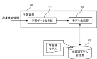
- ⁇ Configuration of the learning device (learning phase)> 6 is a functional block diagram of the learning device 10 according to the present embodiment 1.
- the learning device 10 includes a learning data acquiring unit 11, a model generating unit 12, and a trained model storage unit 15.
- the learning data acquisition unit 11 acquires compressor operation information related to the compressor 4 and refrigeration oil information related to the refrigeration oil 140 in the refrigerant piping 120 as learning data.
- the compressor operation information includes, for example, the motor current Ia, the accumulated operation time TA of the compressor 4, and the remaining amount of refrigeration oil 140 remaining in the compressor 4.
- the refrigeration oil information includes, for example, the brightness of the refrigeration oil 140, the hue of the refrigeration oil 140, image data of the refrigeration oil 140, and video data of the refrigeration oil 140.
- the model generation unit 12 learns the amount of wear debris based on learning data created based on a combination of compressor operation information and refrigeration oil information output from the learning data acquisition unit 11.
- the learning data is data in which the compressor operation information and the refrigeration oil information are mutually associated.
- the learning data is not limited to a combination of compressor operation information and refrigeration oil information, and may be created based on the compressor operation information alone, or may be created based on the refrigeration oil information alone. From the above, a learned model is generated that infers the optimal amount of wear debris from the compressor operation information or the refrigeration oil information.
- the learning device 10 and the inference device 20 are used to learn the amount of wear debris in the refrigerant piping 120, but may be devices connected to the air conditioner 1 via a network, for example, and separate from the air conditioner 1.
- the learning device 10 and the inference device 20 may also be built into the air conditioner 1.
- the learning device 10 and the inference device 20 may exist on a cloud server.
- the learning algorithm used by the model generation unit 12 can be a known algorithm such as supervised learning, unsupervised learning, or reinforcement learning. As an example, we will explain the case where a neural network is applied.
- the model generation unit 12 learns the amount of wear debris by so-called supervised learning, for example, according to a neural network model.
- supervised learning refers to a method in which pairs of input and result (label) data are provided to the learning device 10, and the learning device 10 learns the characteristics of the learning data and infers the result from the input.
- a neural network is composed of an input layer consisting of multiple neurons, an intermediate layer (hidden layer) consisting of multiple neurons, and an output layer consisting of multiple neurons.
- the intermediate layer may be one layer, or two or more layers.
- the neural network learns the amount of wear debris by so-called supervised learning according to learning data created based on compressor operation information or refrigeration oil information acquired by the learning data acquisition unit 11.
- the neural network learns by inputting compressor operation information or refrigeration oil information into the input layer and adjusting the weights W1 and W2 so that the results output from the output layer approach the amount of wear debris.
- the model generation unit 12 generates and outputs a trained model by performing the above-mentioned learning.
- the trained model storage unit 15 stores the trained model output from the model generation unit 12.
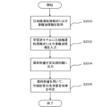
- FIG. 8 is a flowchart showing the learning process by the learning device 10.
- step S100 the learning data acquisition unit 11 acquires compressor operation information and refrigeration oil information. Note that, although the compressor operation information and refrigeration oil information are acquired simultaneously, the compressor operation information and refrigeration oil information data may be acquired at different times.
- step S102 the model generation unit 12 learns the amount of wear debris by so-called supervised learning according to the learning data created based on the combination of the compressor operation information and the refrigeration oil information acquired by the learning data acquisition unit 11, and generates a learned model.
- the learning data is not limited to the combination of the compressor operation information and the refrigeration oil information, and may be created based only on the compressor operation information, or may be created based only on the refrigeration oil information.
- step S104 the trained model storage unit 15 stores the trained model generated by the model generation unit 12.
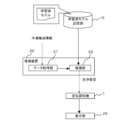
- ⁇ Construction of inference device (utilization phase)> 9 is a functional block diagram of the inference device 20 according to the embodiment 1.
- the inference device 20 includes a data acquisition unit 21 and an inference unit 22.
- the data acquisition unit 21 acquires compressor operation information or refrigeration oil information.
- the inference unit 22 infers the amount of wear debris obtained by using the trained model. That is, by inputting the compressor operation information or refrigeration oil information acquired by the data acquisition unit 21 into this trained model, the amount of wear debris inferred from the compressor operation information or refrigeration oil information can be output.
- the amount of wear debris is output using a trained model trained by the model generation unit of the air conditioner 1, but it is also possible to obtain a trained model from an external source, such as another air conditioner 1, and output the amount of wear debris based on this trained model.
- step S202 the inference unit 22 inputs compressor operation information or refrigeration oil information into the learned model stored in the learned model memory unit 15 to obtain the amount of wear debris.
- step S204 the inference unit 22 outputs the amount of wear debris obtained by the learned model to the air conditioner 1.
- step S206 the air conditioner 1 uses the output amount of wear debris to determine whether or not cleaning of the air conditioner 1 is necessary. If it is determined that cleaning is necessary, a notification is issued that the refrigerant piping 120 needs to be cleaned.
- supervised learning is applied to the learning algorithm used by the model generation unit 12 , but this is not limited to this.
- learning algorithm in addition to supervised learning, reinforcement learning, unsupervised learning, semi-supervised learning, etc. can also be applied.
- the model generation unit 12 may learn the amount of wear powder according to learning data created for multiple air conditioners 1.
- the model generation unit 12 may acquire learning data from multiple air conditioners 1 used in the same area, or may learn the amount of wear powder using learning data collected from multiple air conditioners 1 operating independently in different areas. It is also possible to add or remove air conditioners 1 from which learning data is collected midway.
- the learning device 10 that has learned the amount of wear powder for a certain air conditioner 1 may be applied to another air conditioner 1, and the amount of wear powder for the other air conditioner 1 may be re-learned and updated.
- the learning algorithm used in the model generation unit 12 may be deep learning, which learns to extract the features themselves, or machine learning may be performed according to other known methods, such as genetic programming, functional logic programming, and support vector machines.
- ⁇ Effects of the First Embodiment> by learning the relationship between the compressor operation information, the refrigeration oil information, and the amount of wear powder, it is possible to estimate the amount of wear powder inside the refrigerant pipe 120 based on the acquired compressor operation information (e.g., motor current Ia) or refrigeration oil information (e.g., the brightness and hue of the refrigeration oil 140). By comparing the estimated amount of wear powder with a threshold value, it is possible to determine whether or not an abnormality has occurred inside the refrigerant pipe 120 and in the refrigeration oil 140.
- the acquired compressor operation information e.g., motor current Ia
- refrigeration oil information e.g., the brightness and hue of the refrigeration oil 140
- Embodiment 2 In the first embodiment, the amount of wear powder is inferred based on the compressor operation information or the refrigeration oil 140, but in the second embodiment, the amount of sludge inside the refrigerant pipe 120 (hereinafter, the "sludge amount") is inferred based on the compressor operation information or the refrigeration oil information. Note that the description of matters common to the first embodiment will be omitted, and the description of matters different from the first embodiment will be given.
- Sludge is a type of sludge that occurs when the composition of the refrigeration oil 140 changes due to the high temperature and pressure conditions on the sliding surfaces of the compressor 4. If the sludge penetrates into the inside of the refrigerant piping 120, clogging will occur inside the refrigerant piping 120, affecting the performance and quality of the air conditioner 1.
- the presence of sludge inside the refrigerant piping 120 changes the suction pressure Ps and discharge pressure Pd of the compressor 4, and changes the motor current Ia.
- the refrigeration oil 140 will turn black. Therefore, the amount of sludge can be estimated by acquiring compressor operation information or refrigeration oil information.
- the functional block diagram of the learning device 10 is the same as that of the learning device 10 according to the first embodiment shown in Fig. 6.
- the learning data acquisition unit 11 acquires compressor operation information related to the compressor 4 and refrigeration oil information related to the refrigeration oil 140 in the refrigerant piping 120 as learning data.
- the model generation unit 12 learns the amount of sludge based on learning data created based on a combination of compressor operation information and refrigeration oil information output from the learning data acquisition unit 11.
- the learning data is data in which the compressor operation information and the refrigeration oil information are associated with each other.
- the learning data is not limited to a combination of compressor operation information and refrigeration oil information, and may be created based on only the compressor operation information, or may be created based on only the refrigeration oil information. From the above, a learned model is generated that infers the optimal amount of sludge from the compressor operation information or the refrigeration oil information.
- the model generation unit 12 learns the sludge amount by so-called supervised learning, for example, according to a neural network model.
- the neural network learns the sludge amount by so-called supervised learning, according to learning data created based on a combination of compressor operation information and refrigeration oil information acquired by the learning data acquisition unit 11.
- FIG. 11 is a flowchart showing the learning process performed by the learning device 10.
- step S300 the learning data acquisition unit 11 acquires compressor operation information and refrigeration oil information. Note that, although the compressor operation information and refrigeration oil information are acquired simultaneously, the compressor operation information and refrigeration oil information data may be acquired at different times.
- step S302 the model generation unit 12 learns the sludge amount by so-called supervised learning according to the learning data created based on the combination of the compressor operation information and the refrigeration oil information acquired by the learning data acquisition unit 11, and generates a learned model.
- the learning data is not limited to the combination of the compressor operation information and the refrigeration oil information, and may be created based only on the compressor operation information, or may be created based only on the refrigeration oil information.
- step S304 the learned model storage unit 15 stores the learned model generated by the model generation unit 12.
- the functional block diagram of the inference device 20 is the same as that of the inference device 20 according to the first embodiment shown in FIG.
- the data acquisition unit 21 acquires compressor operation information or refrigeration oil information.
- the inference unit 22 infers the amount of sludge to be obtained using the trained model. That is, by inputting the compressor operation information or refrigeration oil information acquired by the data acquisition unit 21 into this trained model, the amount of sludge inferred from the compressor operation information or refrigeration oil information can be output.
- the sludge amount is output using a trained model trained by the model generation unit of the air conditioner 1, but it is also possible to obtain a trained model from an external source, such as another air conditioner 1, and output the sludge amount based on this trained model.
- step S400 the data acquisition unit 21 acquires compressor operation information or refrigeration oil information.
- step S402 the inference unit 22 inputs the compressor operation information or refrigeration oil information into the learned model stored in the learned model storage unit 15 to obtain the sludge volume.
- step S404 the inference unit 22 outputs the amount of sludge obtained by the learned model to the air conditioner 1.
- step S406 the air conditioner 1 uses the output sludge amount to determine whether or not cleaning of the air conditioner 1 is necessary. If it is determined that cleaning is necessary, a notification is issued that the refrigerant piping 120 needs to be cleaned.
- Embodiment 3 In the first and second embodiments, the case where supervised learning is used has been described, but the cleaning necessity information of the inside of the refrigerant pipe 120 can also be estimated by using unsupervised learning as in the third embodiment. The case where unsupervised learning is used will be described below.
- Fig. 14 is a functional block diagram of a learning device 10 according to the third embodiment.
- a learning data acquisition unit 11 acquires compressor operation information related to the compressor 4 as learning data.
- the compressor operation information includes, for example, the motor current Ia of the compressor 4.
- the model generation unit 12 learns whether or not the refrigerant pipes 120 need to be cleaned based on the learning data created based on the compressor operation information output from the learning data acquisition unit 11. That is, it generates a learned model that infers whether or not cleaning is needed from the compressor operation information of the air conditioner 1.
- the learning data is data that associates the compressor operation information and whether or not cleaning is needed with each other.
- the trained model can be configured as a model for classifying (clustering) into one of multiple cluster groups consisting of compressor operation information when the air conditioner 1 is operating (normally) within a specified period (e.g., within 1 to 5 years) after the air conditioner 1 is newly installed or the refrigerant piping 120 is cleaned.
- the learning algorithm used by the model generation unit 12 can be a known algorithm such as supervised learning, unsupervised learning, or reinforcement learning.
- K-means clustering
- Unsupervised learning is a method of learning features in learning data that does not contain results (labels) by providing the learning device 10 with the learning data.
- the model generation unit 12 learns whether cleaning is necessary by so-called unsupervised learning, for example, according to a grouping method using the K-means method.
- K-means is a non-hierarchical clustering algorithm that uses the cluster mean to classify a given number of clusters into k.
- the K-means algorithm is processed as follows. First, a cluster is randomly assigned to each data x i . Next, the center V j of each cluster is calculated based on the assigned data. Next, the distance between each x i and each V j is found, and x i is reassigned to the cluster with the closest center. Then, if the cluster assignment for all x i has not changed in the above process, or if the amount of change falls below a certain threshold value set in advance, it is determined that convergence has occurred and the process ends.
- the system learns whether cleaning is necessary by so-called unsupervised learning in accordance with learning data created based on compressor operation information acquired by the learning data acquisition unit 11.
- the model generation unit 12 generates and outputs a trained model by performing the above-mentioned learning.
- the trained model storage unit 15 stores the trained model output from the model generation unit 12.
- FIG. 15 is a flowchart showing the learning process by the learning device 10.
- step S500 the learning data acquisition unit 11 acquires compressor operation information.
- step S502 the model generation unit 12 learns whether cleaning is necessary by so-called unsupervised learning according to the learning data created based on the compressor operation information acquired by the learning data acquisition unit 11, and generates a learned model.
- step S504 the trained model storage unit 15 stores the trained model generated by the model generation unit 12.
- FIG. 16 is a functional block diagram of an inference device 20 according to the third embodiment.
- the data acquisition unit 21 acquires compressor operation information.
- the inference unit 22 infers whether cleaning is necessary by using the learned model stored in the learned model storage unit 15. That is, by inputting the compressor operation information acquired by the data acquisition unit 21 into this learned model, it is possible to infer which cluster the compressor operation information belongs to and output the inference result as whether cleaning is necessary.
- the inference unit 22 infers that the amount of wear powder and sludge inside the refrigerant piping 120 is within a specified range, and that cleaning of the refrigerant piping 120 is unnecessary. Also, if the data input to the trained model does not belong to any cluster indicating when the air conditioner 1 is operating (normally) within a specified period, the inference unit infers that the amount of wear powder and sludge inside the refrigerant piping 120 is greater than a specified range, and that cleaning of the refrigerant piping 120 is necessary.
- the need for cleaning is output using a trained model trained by the model generation unit 12 of the air conditioner 1.
- a trained model may be obtained from an external source, such as another air conditioner 1, and the need for cleaning may be output based on this trained model.
- the inference unit 22 outputs the necessity for cleaning obtained based on the compressor operation information to the display unit 25 of the air conditioner 1.
- the display unit 25 may be, for example, a remote control for operating the air conditioner 1, a smartphone held by a user or worker, or an alarm device that emits sound.
- step S600 the data acquisition unit 21 acquires compressor operation information.
- step S602 the inference unit 22 inputs the compressor operation information into the learned model stored in the learned model storage unit 15 to obtain whether cleaning is required.
- step S604 the inference unit 22 outputs the cleaning necessity obtained from the trained model to the air conditioner 1.
- step S606 the air conditioner 1 uses the output cleaning necessity to display on a remote control or smartphone whether cleaning is necessary or not, or to issue an alarm from an alarm device. This allows the user and worker to be notified of whether cleaning of the refrigerant pipes 120 is necessary, and to be prompted to perform cleaning if cleaning is necessary.
- the learning algorithm used in the learning device 10 may be deep learning, which learns to extract the features themselves, or other known methods.
- the method is not limited to the non-hierarchical clustering using the k-means method described above, and any other known method capable of clustering may be used.
- hierarchical clustering such as the shortest distance method may be used.
- the learning device 10 and the inference device 20 may be connected to the air conditioner 1 via a network, for example, and may be separate devices from the air conditioner 1.
- the learning device 10 and the inference device 20 may also be built into the air conditioner 1.
- the learning device 10 and the inference device 20 may exist on a cloud server.
- the model generation unit 12 may learn whether cleaning is necessary according to learning data created for multiple air conditioners 1.
- the model generation unit 12 may acquire learning data from multiple air conditioners 1 used in the same area, or may learn whether cleaning is necessary using learning data collected from multiple air conditioners 1 operating independently in different areas. It is also possible to add or remove air conditioners 1 from which learning data is collected midway through the process. Furthermore, the learning device 10 that has learned whether cleaning is necessary for a certain air conditioner 1 may be applied to another air conditioner 1, and the cleaning necessity for the other air conditioner 1 may be re-learned and updated.
- Embodiment 4 In the third embodiment, a configuration in which the necessity of cleaning of the refrigerant pipes 120 is inferred based on compressor operation information is described, whereas in the fourth embodiment, a configuration in which the necessity of cleaning of the refrigerant pipes 120 is inferred based on refrigeration oil information is described. Note that a description of matters common to the third embodiment will be omitted, and matters different from the third embodiment will be described.
- Fig. 18 is a functional block diagram of a learning device 10 according to the fourth embodiment.
- a learning data acquisition unit 11 acquires refrigeration oil information related to the refrigeration oil 140 in the refrigerant pipe 120 as learning data.
- the refrigeration oil information includes, for example, the lightness and hue of the refrigeration oil 140.
- the model generation unit 12 learns whether or not the refrigerant pipes 120 need to be cleaned based on the learning data created based on the refrigeration oil information output from the learning data acquisition unit 11. That is, it generates a learned model that infers whether or not cleaning is needed from the refrigeration oil information of the air conditioner 1.
- the learning data is data that associates the refrigeration oil information and the need for cleaning with each other.
- the trained model can be configured as a model for classifying (clustering) the refrigeration oil information when the air conditioner 1 is operating (normally) within a specified period (e.g., within 1 to 5 years) after the air conditioner 1 is newly installed or the refrigerant piping 120 is cleaned, into one of multiple cluster groups made up of the refrigeration oil information when the air conditioner 1 is operating (normally) within the specified period.
- a specified period e.g., within 1 to 5 years
- the need for cleaning is learned by so-called unsupervised learning according to learning data created based on refrigeration oil information acquired by the learning data acquisition unit 11.
- step S700 the learning data acquisition unit 11 acquires refrigeration oil information.
- step S702 the model generation unit 12 learns whether cleaning is necessary by so-called unsupervised learning according to the learning data created based on the refrigeration oil information acquired by the learning data acquisition unit 11, and generates a learned model.
- step S704 the trained model storage unit 15 stores the trained model generated by the model generation unit 12.
- FIG. 20 is a functional block diagram of an inference device 20 according to the fourth embodiment.
- the data acquisition unit 21 acquires refrigeration oil information.
- the inference unit 22 infers whether or not cleaning is required by utilizing the learned model stored in the learned model storage unit 15. That is, by inputting the refrigeration oil information acquired by the data acquisition unit 21 into this learned model, it is possible to infer which cluster the refrigeration oil information belongs to and output the inference result as whether or not cleaning is required.
- the inference unit 22 infers that the amount of wear powder and sludge inside the refrigerant piping 120 is within a specified range, and that cleaning of the refrigerant piping 120 is unnecessary. Also, if the data input to the trained model does not belong to any cluster that indicates when the air conditioner 1 is operating (normally) within a specified period, the inference unit infers that the amount of wear powder and sludge inside the refrigerant piping 120 is greater than a specified range, and that cleaning of the refrigerant piping 120 is necessary.
- the inference unit 22 outputs the necessity for cleaning obtained based on the refrigeration oil information to the display unit 25 of the air conditioner 1.
- step S800 the data acquisition unit 21 acquires refrigeration oil information.
- step S802 the inference unit 22 inputs the refrigeration oil information into the learned model stored in the learned model storage unit 15 to obtain the need for cleaning.
- step S804 the inference unit 22 outputs the cleaning necessity obtained from the trained model to the air conditioner 1.
- step S806 the air conditioner 1 uses the output cleaning necessity to display on a remote control or smartphone whether cleaning is necessary or to issue an alarm from an alarm device. This notifies the user and worker whether cleaning of the refrigerant pipe 120 is necessary and urges cleaning if cleaning is necessary.
- Embodiment 5 a form in which the amount of wear particles is estimated based on a filter in refrigerant pipe 120 will be described.
- ⁇ Estimation of wear debris amount based on filters in refrigerant piping> As a means for estimating the amount of wear debris, a removable filter 125 is provided inside the refrigerant pipe 120, the amount of wear debris captured by the filter 125 is obtained, and this information is used.
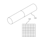
- Figures 22-23 show schematic diagrams of a filter 125 installed inside the refrigerant piping 120.
- Figure 22 shows the filter 125 installed in the refrigerant piping 120
- Figure 23 shows the filter 125 removed from the refrigerant piping 120.
- wear particles generated by the compressor 4 while the air conditioner 1 is operating are collected by the filter 125.
- the filter 125 By removing the filter 125 from the refrigerant piping 120 as shown in FIG. 23 and sampling the wear particles collected by the filter 125, it is possible to estimate the amount of wear particles generated inside the refrigerant piping 120.
- the accuracy of estimating the amount of wear debris or sludge inside the refrigerant pipe 120 can be improved.
- Embodiment 6 an air conditioner 1 will be described that, when the cleaning necessity estimated in the first to fifth embodiments is output as "cleaning necessary,” controls are performed to prohibit a so-called oil return operation in which the refrigeration oil 140 inside the refrigerant pipes 120 is returned to the compressor 4.
- Fig. 24 is a flowchart relating to the operation of the air conditioner 1 in this sixth embodiment.
- step S900 the necessity of cleaning is output to the air conditioner 1. If it is determined in step S902 that cleaning is necessary, the oil return operation is prohibited in step S904. If it is determined in step S902 that cleaning is not necessary, step S904 is not executed.
- Air conditioner 4 Compressor, 10 Learning device, 11 Learning data acquisition unit, 12 Model generation unit, 15 Learned model storage unit, 20 Inference device, 21 Data acquisition unit, 22 Inference unit, 25 Display unit, 30 Communication unit, 50 Motor, 51 Rotor, 52 Stator, 60 Crankshaft, 60a Shaft main body, 60b Eccentric shaft, 70 Compression mechanism, 71 Cylinder, 71a Intake port, 71b Cylinder chamber, 71c Vane groove, 71d Back pressure chamber, 72 Intake pipe, 80 Rolling piston, 81 Vane, 82 Upper bearing unit, 83 Upper discharge muffler, 83a Muffler chamber, 84 Lower bearing unit, 85 Lower discharge muffler, 85a muffler chamber, 86 space, 86a suction chamber, 86b compression chamber, 90 sealed container, 91 discharge pipe, 92 terminal, 93 lead wire, 110 refrigerant flow path, 111 outdoor heat exchanger, 112 outdoor blower, 113 four-way valve, 114 expansion valve, 115
Landscapes
- Engineering & Computer Science (AREA)
- Mechanical Engineering (AREA)
- General Engineering & Computer Science (AREA)
- Health & Medical Sciences (AREA)
- Biomedical Technology (AREA)
- Chemical & Material Sciences (AREA)
- Combustion & Propulsion (AREA)
- Physics & Mathematics (AREA)
- Thermal Sciences (AREA)
- Applications Or Details Of Rotary Compressors (AREA)
Abstract
Lorsqu'une anomalie se produit dans une partie coulissante d'un compresseur, une poudre d'abrasion peut être générée depuis la partie coulissante et peut pénétrer dans une conduite de fluide frigorigène. Dans ce cas, un colmatage peut se produire dans la conduite de fluide frigorigène en raison de la poudre d'abrasion, et une anomalie peut se produire dans un climatiseur. Le but de la présente invention est de fournir un dispositif d'apprentissage pour estimer des informations concernant l'intérieur d'une conduite de fluide frigorigène et notifier si un nettoyage de la conduite doit être effectué. L'invention concerne un dispositif d'apprentissage comprenant : une unité d'acquisition de données d'apprentissage qui acquiert des informations sur le fonctionnement du compresseur et des informations sur l'huile de réfrigérateur d'un climatiseur ; et une unité de génération de modèle qui génère un modèle appris pour inférer la quantité de poudre d'abrasion générée depuis un compresseur du climatiseur sur la base des informations sur le fonctionnement du compresseur ou des informations sur l'huile de réfrigérateur.
Priority Applications (1)
| Application Number | Priority Date | Filing Date | Title |
|---|---|---|---|
| PCT/JP2023/030438 WO2025041327A1 (fr) | 2023-08-24 | 2023-08-24 | Dispositif d'apprentissage, dispositif d'inférence, climatiseur, procédé d'inférence, procédé de commande pour climatiseur, et programme de commande associé |
Applications Claiming Priority (1)
| Application Number | Priority Date | Filing Date | Title |
|---|---|---|---|
| PCT/JP2023/030438 WO2025041327A1 (fr) | 2023-08-24 | 2023-08-24 | Dispositif d'apprentissage, dispositif d'inférence, climatiseur, procédé d'inférence, procédé de commande pour climatiseur, et programme de commande associé |
Publications (1)
| Publication Number | Publication Date |
|---|---|
| WO2025041327A1 true WO2025041327A1 (fr) | 2025-02-27 |
Family
ID=94731789
Family Applications (1)
| Application Number | Title | Priority Date | Filing Date |
|---|---|---|---|
| PCT/JP2023/030438 Pending WO2025041327A1 (fr) | 2023-08-24 | 2023-08-24 | Dispositif d'apprentissage, dispositif d'inférence, climatiseur, procédé d'inférence, procédé de commande pour climatiseur, et programme de commande associé |
Country Status (1)
| Country | Link |
|---|---|
| WO (1) | WO2025041327A1 (fr) |
Citations (12)
| Publication number | Priority date | Publication date | Assignee | Title |
|---|---|---|---|---|
| JPH04356673A (ja) * | 1991-05-31 | 1992-12-10 | Aisin Seiki Co Ltd | 空調機器の洗浄方法 |
| JPH08100968A (ja) * | 1994-09-30 | 1996-04-16 | Sanyo Electric Co Ltd | 冷凍装置 |
| JPH0933114A (ja) * | 1995-07-19 | 1997-02-07 | Daikin Ind Ltd | 冷凍装置 |
| JPH10103241A (ja) * | 1996-09-30 | 1998-04-21 | Sanyo Electric Co Ltd | 密閉型圧縮機およびそれを用いた冷凍装置 |
| JP2001227828A (ja) * | 2000-02-17 | 2001-08-24 | Daikin Ind Ltd | 冷凍装置 |
| JP2005083637A (ja) * | 2003-09-08 | 2005-03-31 | Daikin Ind Ltd | 冷凍装置 |
| JP2010065982A (ja) * | 2008-09-12 | 2010-03-25 | Mitsubishi Electric Corp | 冷凍サイクル装置 |
| JP2010151388A (ja) * | 2008-12-25 | 2010-07-08 | Mitsubishi Electric Corp | 空気調和装置 |
| WO2013191273A1 (fr) * | 2012-06-22 | 2013-12-27 | ナブテスコ株式会社 | Procédé de détermination d'état, système de notification d'état et programme de détermination d'état |
| WO2014203356A1 (fr) * | 2013-06-19 | 2014-12-24 | 三菱電機株式会社 | Dispositif de cycle de réfrigération |
| WO2018042495A1 (fr) * | 2016-08-29 | 2018-03-08 | 三菱電機株式会社 | Appareil à cycle de réfrigération |
| JP2020003166A (ja) * | 2018-06-29 | 2020-01-09 | 日立ジョンソンコントロールズ空調株式会社 | 冷凍機油劣化判定システム、水分混入判定システム、冷凍サイクル装置及び水分残存検査方法 |
-
2023
- 2023-08-24 WO PCT/JP2023/030438 patent/WO2025041327A1/fr active Pending
Patent Citations (12)
| Publication number | Priority date | Publication date | Assignee | Title |
|---|---|---|---|---|
| JPH04356673A (ja) * | 1991-05-31 | 1992-12-10 | Aisin Seiki Co Ltd | 空調機器の洗浄方法 |
| JPH08100968A (ja) * | 1994-09-30 | 1996-04-16 | Sanyo Electric Co Ltd | 冷凍装置 |
| JPH0933114A (ja) * | 1995-07-19 | 1997-02-07 | Daikin Ind Ltd | 冷凍装置 |
| JPH10103241A (ja) * | 1996-09-30 | 1998-04-21 | Sanyo Electric Co Ltd | 密閉型圧縮機およびそれを用いた冷凍装置 |
| JP2001227828A (ja) * | 2000-02-17 | 2001-08-24 | Daikin Ind Ltd | 冷凍装置 |
| JP2005083637A (ja) * | 2003-09-08 | 2005-03-31 | Daikin Ind Ltd | 冷凍装置 |
| JP2010065982A (ja) * | 2008-09-12 | 2010-03-25 | Mitsubishi Electric Corp | 冷凍サイクル装置 |
| JP2010151388A (ja) * | 2008-12-25 | 2010-07-08 | Mitsubishi Electric Corp | 空気調和装置 |
| WO2013191273A1 (fr) * | 2012-06-22 | 2013-12-27 | ナブテスコ株式会社 | Procédé de détermination d'état, système de notification d'état et programme de détermination d'état |
| WO2014203356A1 (fr) * | 2013-06-19 | 2014-12-24 | 三菱電機株式会社 | Dispositif de cycle de réfrigération |
| WO2018042495A1 (fr) * | 2016-08-29 | 2018-03-08 | 三菱電機株式会社 | Appareil à cycle de réfrigération |
| JP2020003166A (ja) * | 2018-06-29 | 2020-01-09 | 日立ジョンソンコントロールズ空調株式会社 | 冷凍機油劣化判定システム、水分混入判定システム、冷凍サイクル装置及び水分残存検査方法 |
Similar Documents
| Publication | Publication Date | Title |
|---|---|---|
| Kocyigit | Fault and sensor error diagnostic strategies for a vapor compression refrigeration system by using fuzzy inference systems and artificial neural network | |
| CN112166253B (zh) | 制冷装置 | |
| EP1802926A2 (fr) | Diagnostic et pronostic de defaillances bases sur des classifieurs de defaillances a distance | |
| JP2010065998A (ja) | パラメータを監視する方法及び冷却装置 | |
| Lin et al. | Experimental investigation of startup characteristics of R290 rotary compressor under low ambient temperature heating condition | |
| EP3314175B1 (fr) | Procédé de production de refrigeration avec r1233zd | |
| KR20210002281A (ko) | 의류처리장치 | |
| CN112012929B (zh) | 压缩机润滑油质量管理 | |
| WO1996013666A1 (fr) | Compresseur rotatif et machine frigorifique | |
| JP2018087528A (ja) | 密閉型圧縮機および冷凍サイクル装置 | |
| WO2025041327A1 (fr) | Dispositif d'apprentissage, dispositif d'inférence, climatiseur, procédé d'inférence, procédé de commande pour climatiseur, et programme de commande associé | |
| Chang et al. | Reliability evaluation of scroll compressor for system air conditioner | |
| CN103335376B (zh) | 空调系统控制方法 | |
| JP2023142131A (ja) | 冷媒量診断装置、冷媒システム及び冷媒量診断方法 | |
| JP2020505544A (ja) | スピンドル圧縮機として機能する乾式容積型装置を含む蒸気圧縮機 | |
| JP2014129802A (ja) | 冷凍装置 | |
| Creamaschi et al. | Experimental study of compressor operating characteristics and performance when using refrigerants R32, R1234yf, and two new low GWP developmental refrigerants as drop-in replacements for R410A | |
| JPH10148408A (ja) | 冷凍装置 | |
| JP3480076B2 (ja) | 室外機 | |
| CN110608162B (zh) | 压缩机的润滑剂质量管理 | |
| CN117073131A (zh) | 空调设备 | |
| JP2009185795A (ja) | 圧縮機の故障診断方法および故障診断装置 | |
| JP3887649B2 (ja) | 圧縮機 | |
| CN117053346B (zh) | 一种空调故障检测方法、装置及空调 | |
| JP7807939B2 (ja) | 冷凍装置、リソグラフィ装置、物品製造方法、ならびに、冷凍装置の制御装置および制御方法 |
Legal Events
| Date | Code | Title | Description |
|---|---|---|---|
| 121 | Ep: the epo has been informed by wipo that ep was designated in this application |
Ref document number: 23949783 Country of ref document: EP Kind code of ref document: A1 |
|
| NENP | Non-entry into the national phase |
Ref country code: DE |