WO2025041333A1 - Compresseur de suralimentation - Google Patents
Compresseur de suralimentation Download PDFInfo
- Publication number
- WO2025041333A1 WO2025041333A1 PCT/JP2023/030493 JP2023030493W WO2025041333A1 WO 2025041333 A1 WO2025041333 A1 WO 2025041333A1 JP 2023030493 W JP2023030493 W JP 2023030493W WO 2025041333 A1 WO2025041333 A1 WO 2025041333A1
- Authority
- WO
- WIPO (PCT)
- Prior art keywords
- vane
- passage
- scroll
- turbocharger
- scroll passage
- Prior art date
- Legal status (The legal status is an assumption and is not a legal conclusion. Google has not performed a legal analysis and makes no representation as to the accuracy of the status listed.)
- Pending
Links
Images


Classifications
-
- F—MECHANICAL ENGINEERING; LIGHTING; HEATING; WEAPONS; BLASTING
- F01—MACHINES OR ENGINES IN GENERAL; ENGINE PLANTS IN GENERAL; STEAM ENGINES
- F01D—NON-POSITIVE DISPLACEMENT MACHINES OR ENGINES, e.g. STEAM TURBINES
- F01D9/00—Stators
- F01D9/02—Nozzles; Nozzle boxes; Stator blades; Guide conduits, e.g. individual nozzles
-
- F—MECHANICAL ENGINEERING; LIGHTING; HEATING; WEAPONS; BLASTING
- F02—COMBUSTION ENGINES; HOT-GAS OR COMBUSTION-PRODUCT ENGINE PLANTS
- F02B—INTERNAL-COMBUSTION PISTON ENGINES; COMBUSTION ENGINES IN GENERAL
- F02B39/00—Component parts, details, or accessories relating to, driven charging or scavenging pumps, not provided for in groups F02B33/00 - F02B37/00
Definitions
- This disclosure relates to a turbocharger.
- Patent Document 1 discloses a turbocharger with movable vanes.
- This turbocharger has two scroll passages, and the movable vanes that face the ends of each scroll passage are larger than the other movable vanes.
- These large movable vanes are movable between a position that connects the two scroll passages to each other and a position that blocks the two scroll passages from each other. During low-speed operation, these large movable vanes block the two scroll passages from each other.
- Patent Document 2 also discloses a turbocharger equipped with a movable seal vane.
- This turbocharger has two scroll passages, and a seal vane facing the end of each scroll passage is configured to open and close a bypass between the two scroll passages.
- the seal vane opens the bypass in order to actively reduce the efficiency of the turbocharger.
- the present disclosure aims to provide a turbocharger that can suppress exhaust gas leakage between two scroll passages.
- a turbocharger includes a housing including a space that accommodates an impeller, a first scroll passage and a second scroll passage located outside the space in the radial direction of the impeller, and a connecting passage that connects the first scroll passage and the second scroll passage to the space, and a plurality of fixed vanes arranged in the connecting passage, the vanes including a first vane formed integrally with a wall that radially separates each scroll passage and the connecting passage, and a second vane arranged between the first vanes in the circumferential direction of the impeller.
- a turbocharger includes a housing including a space that accommodates an impeller, a first scroll passage and a second scroll passage located outside the space in the radial direction of the impeller, and a connecting passage that connects the first scroll passage and the second scroll passage to the space, and a plurality of fixed vanes disposed in the connecting passage, where the distance between the vane and a wall that radially separates each scroll passage and the connecting passage is smallest at the tongue of each scroll passage.
- the plurality of fixed vanes may include a first vane closest to the tongue of each scroll passage and a second vane disposed between the first vanes in the circumferential direction of the impeller, and the length of the first vane may be greater than the length of the second vane.
- the first vane may contact the corresponding tongue.
- the first vane and the corresponding tongue may have a gap between them, and the ratio of the area of the gap to the total area of all the throats between the multiple fixed vanes may be greater than 0% and less than or equal to 4%.
- the above percentage may be 2% or less.
- FIG. 1 is a schematic cross-sectional view of a turbocharger according to a first embodiment.
- FIG. 2 is a schematic cross-sectional view taken along line II-II in FIG.
- FIG. 3 is a schematic cross-sectional view showing a turbocharger according to the second embodiment.
- FIG. 4 is a schematic cross-sectional view showing a turbocharger according to the third embodiment.
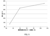
- FIG. 5 is a graph illustrating how the gap between the first vane and the tongue affects the amount of leakage.
- FIG. 1 is a schematic cross-sectional view of a turbocharger 100 according to the first embodiment.
- the turbocharger 100 according to this embodiment is applied to, for example, a ship engine.
- the application of the turbocharger 100 is not limited to this, and the turbocharger 100 may be applied to various machines other than ships.
- the turbocharger 100 includes a housing 1, a shaft 7, a turbine impeller 8, and a compressor impeller 9.
- the turbine impeller 8 and the compressor impeller 9 rotate integrally with the shaft 7. Therefore, the central axial direction, radial direction, and circumferential direction of the shaft 7 are common to the turbine impeller 8 and the compressor impeller 9.
- the central axial direction, radial direction, and circumferential direction of the shaft 7, the turbine impeller 8, and the compressor impeller 9 may be referred to simply as the "central axial direction,” the "radial direction,” and the “circumferential direction,” respectively, unless otherwise specified.
- the housing 1 includes a bearing housing 2, a turbine housing 3, and a compressor housing 4.
- a fastening mechanism 21a such as a G coupling.
- the other end of the bearing housing 2 is connected to the compressor housing 4 by a fastening mechanism 21b such as a fastening bolt.
- the bearing housing 2 includes a bearing hole 22.
- the bearing hole 22 extends in the central axis direction within the bearing housing 2.
- the bearing hole 22 accommodates the bearings 50 and 60.
- the bearings 50 and 60 rotatably support the shaft 7.
- a turbine impeller 8 is provided at a first end of the shaft 7 in the central axial direction.
- the turbine housing 3 includes a first space SP1 that rotatably houses the turbine impeller 8.
- a compressor impeller 9 is provided at a second end of the shaft 7 opposite the first end in the central axial direction.
- the compressor housing 4 includes a second space SP2 that rotatably houses the compressor impeller 9.
- the compressor housing 4 includes an intake port 10 at the end opposite the bearing housing 2 in the central axial direction.
- the intake port 10 is connected to an air cleaner (not shown).
- the bearing housing 2 and the compressor housing 4 define a diffuser passage 11 therebetween.
- the diffuser passage 11 has an annular shape.
- the diffuser passage 11 is located radially outward relative to the compressor impeller 9 and the second space SP2.
- the diffuser passage 11 communicates with the intake port 10 via the second space SP2.
- the compressor housing 4 includes a compressor scroll passage 12.
- the compressor scroll passage 12 is located radially outward of the diffuser passage 11.
- the compressor scroll passage 12 communicates with the diffuser passage 11.
- the compressor scroll passage 12 also communicates with an intake port of an engine (not shown).
- the turbine housing 3 includes a discharge port 13 at the end opposite the bearing housing 2 in the central axis direction.
- the discharge port 13 is connected to an exhaust gas purification device (not shown).
- FIG. 2 is a schematic cross-sectional view taken along line II-II in FIG. 1.
- the turbine housing 3 includes a connecting passage 14, a first scroll passage 15, and a second scroll passage 16. That is, the turbine Tb is a double scroll turbine.
- the connecting passage 14 has an annular shape.
- the connecting passage 14 connects the first scroll passage 15 and the second scroll passage 16 to the first space SP1.
- the connecting passage 14 is located radially outside the turbine impeller 8 and the first space SP1.
- a plurality of fixed vanes V are arranged in the connecting passage 14. The vanes V will be described in detail later.
- the first scroll passage 15 is located radially outside the connecting passage 14.
- the first scroll passage 15 and the connecting passage 14 are radially separated from each other by a wall W1.
- the second scroll passage 16 is partially located radially outside the first scroll passage 15 and partially located radially outside the connecting passage 14.
- the second scroll passage 16 and the connecting passage 14 are radially separated from each other by a wall W2.
- Each of the first scroll passage 15 and the second scroll passage 16 communicates with a gas inlet (not shown).
- the gas inlet receives exhaust gas discharged from an exhaust manifold of the engine (not shown).
- exhaust gas is guided from the gas inlet to the first scroll passage 15 and the second scroll passage 16, and is further guided to the discharge port 13 via the connecting passage 14 and the first space SP1.
- the exhaust gas rotates the turbine impeller 8 as it passes through the space between the blades of the turbine impeller 8.
- the rotational force of the turbine impeller 8 is transmitted to the compressor impeller 9 via the shaft 7.
- the air is pressurized as described above.
- the pressurized air is then directed to the engine intake port.
- the vanes V are arranged in the connecting passage 14 at intervals along the circumferential direction.
- the vanes V include a first vane V1 and a second vane V2.
- the first vane V1 is formed integrally with the walls W1 and W2. That is, the innermost part of the first vane V1 in the radial direction defines the tongue T1 of the first scroll passage 15 and the tongue T2 of the second scroll passage 16.
- "tongue” means the circumferential end of the walls W1 and W2 that radially separate the scroll passages 15 and 16 and the connecting passage 14. Therefore, there is no gap between the first vane V1 and the walls W1 and W2.
- a leakage flow may occur from the first scroll passage 15 to the second scroll passage 16, or from the second scroll passage 16 to the first scroll passage 15, in the direction opposite to the flow F of the exhaust gas (see, for example, leakage flows L1 and L2 in FIG. 4).
- leakage flows L1 and L2 in FIG. 4 see, for example, leakage flows L1 and L2 in FIG. 4.
- FIG. 2 in this embodiment, there is no gap between the first vane V1 and the walls W1 and W2, so such leakage flow can be blocked.
- the surface of the first vane V1 is smoothly continuous with the radially outer surface of the wall W1, i.e., the surface that defines the first scroll passage 15.
- the surface of the first vane V1 is also smoothly continuous with the radially inner surface of the wall W1, i.e., the surface that defines the connecting passage 14.
- the joint between the surface of the first vane V1 and the radially inner surface of the wall W1 may have an uneven portion such as a recess or protrusion.
- the surface of the first vane V1 is smoothly continuous with the radially outer surface of the wall W2, i.e., the surface that defines the second scroll passage 16.
- the surface of the first vane V1 is also smoothly continuous with the radially inner surface of the wall W2, i.e., the surface that defines the connecting passage 14.
- the joint between the surface of the first vane V1 and the radially inner surface of the wall W2 may have an uneven portion such as a recess or protrusion.
- the second vane V2 is located between the two first vanes V1 in the circumferential direction.
- the second vane V2 is spaced apart from the walls W1 and W2.
- the second vane V2 is inclined in the circumferential direction so that the downstream end, i.e., the trailing edge, in the flow direction F is located radially inward from the upstream end, i.e., the leading edge.
- the first vane V1 differs from the second vane V2 in that the first vane V1 is integrally formed with the walls W1 and W2, and in other respects, the first vane V1 may be substantially the same as the second vane V2. Specifically, the radially inner portion of the first vane V1 may be the same as or substantially the same as the radially inner portion of the second vane V2.
- the turbocharger 100 as described above includes a turbine housing 3 including a first space SP1 that accommodates a turbine impeller 8, a first scroll passage 15 and a second scroll passage 16 located radially outside the first space SP1, a connecting passage 14 that connects the first scroll passage 15 and the second scroll passage 16 to the first space SP1, and a plurality of fixed vanes V arranged in the connecting passage 14.
- the vanes V include a first vane V1 that is integrally formed with the walls W1 and W2 that radially separate the scroll passages 15 and 16 and the connecting passage 14, and a second vane V2 that is arranged between the first vanes V1 in the circumferential direction. With this configuration, there is no gap between the first vane V1 and the walls W1 and W2, so that leakage flow from the first scroll passage 15 to the second scroll passage 16 or leakage flow from the second scroll passage 16 to the first scroll passage 15 can be blocked.
- FIG. 3 is a schematic cross-sectional view showing a turbocharger 200 according to a second embodiment.
- the turbocharger 200 differs from the turbocharger 100 described above in that the first vane V1 is separate from the walls W1 and W2. In other respects, the turbocharger 200 may be the same as the turbocharger 100.
- the first vane V1 is separate from the walls W1 and W2. Therefore, the tongue portion T1 of the first scroll passage 15 and the tongue portion T2 of the second scroll passage 16 are separate from the first vane V1.
- the distance between the vane V and the walls W1, W2 is smallest at the tongues T1, T2.
- the first vane V1 is formed continuously with the tongues T1, T2. In other words, the first vane V1 contacts the tongues T1, T2. Therefore, there is no gap between the first vane V1 and the tongues T1, T2. That is, the distance between the first vane V1 and the tongues T1, T2 is zero. Therefore, the distance between the first vane V1 and the walls W1, W2, i.e., the distance between the first vane V1 and the tongues T1, T2, is smaller than the distance d between the second vane V2 and the walls W1, W2.
- the length of the first vane V1 is greater than the length of the second vane V2.
- the "length" of the first vane V1 and the second vane V2 means the length of the line segment connecting the leading edge and trailing edge of each vane.
- the turbocharger 200 as described above includes a turbine housing 3 including a first space SP1 that accommodates a turbine impeller 8, a first scroll passage 15 and a second scroll passage 16 that are located radially outside the first space SP1, a connecting passage 14 that connects the first scroll passage 15 and the second scroll passage 16 to the first space SP1, and a plurality of fixed vanes V arranged in the connecting passage 14.
- the distance between the vane V and the walls W1, W2 that radially separate the scroll passages 15, 16 and the connecting passage 14 is smallest at the tongues T1, T2 of the scroll passages 15, 16.
- the gap at the tongues T1, T2 can be made smaller than the distance d between the vane V and the walls W1, W2 at other positions, thereby suppressing leakage flow at the tongues T1, T2.
- the multiple fixed vanes V include a first vane V1 closest to the tongues T1, T2 of each scroll passage 15, 16, and a second vane V2 arranged between the first vanes V1 in the circumferential direction, and the length of the first vane V1 is greater than the length of the second vane V2.
- the first vane V1 contacts the corresponding tongue portions T1, T2. With this configuration, there is no gap between the first vane V1 and the tongue portions T1, T2, so leakage flow can be blocked.
- FIG. 4 is a schematic cross-sectional view showing a turbocharger 300 according to a third embodiment.
- the turbocharger 300 differs from the turbocharger 200 described above in that the first vane V1 is spaced apart from the walls W1 and W2. In other respects, the turbocharger 300 may be the same as the turbocharger 200.
- the first vane V1 is spaced apart from the tongue portions T1 and T2. In other words, the first vane V1 is not in contact with the tongue portions T1 and T2. Therefore, a gap g is formed between the first vane V1 and the tongue portions T1 and T2. In this configuration, a leakage flow L1 from the first scroll passage 15 to the second scroll passage 16, or a leakage flow L2 from the second scroll passage 16 to the first scroll passage 15 may occur in the gap g.
- Figure 5 is a graph that explains how the gap g between the first vane V1 and the tongues T1, T2 affects the amount of leakage.
- the leakage flows L1, L2 in the turbocharger 300 shown in Figure 4 were analyzed using CFD (Computational Fluid Dynamics).
- the horizontal axis of the graph indicates the percentage r (%) of the area of each gap g to the total throat area between the vanes V.
- the area of each throat is obtained from the cross section of the flow path at the position where the distance between two adjacent vanes is shortest when viewed in the central axial direction.
- the area of the gap g is obtained from the cross section of the gap g at the position where the distance between the first vane and the tongues T1, T2 is shortest when viewed in the central axial direction.
- the percentage r indicates the percentage of the area of the gap g in each tongue T1, T2 to the total throat area, i.e., the area of the gap g in one of the tongues T1, T2.
- the vertical axis of the graph shows the amount of leakage (%).
- the ratio r decreases, i.e., as the gap g decreases, the amount of leakage also decreases.
- the amount of leakage decreases sharply when the ratio r is approximately 4%. Therefore, it can be seen that the amount of leakage can be significantly reduced by designing the gap g so that the ratio r is 4% or less. It can also be seen that if the ratio r is approximately 2% or less, the amount of leakage can be suppressed to a small value of 20% or less.
- Turbine housing 8 Turbine impeller 14 Connection passage 15 First scroll passage 16 Second scroll passage 100
Landscapes
- Engineering & Computer Science (AREA)
- Mechanical Engineering (AREA)
- General Engineering & Computer Science (AREA)
- Chemical & Material Sciences (AREA)
- Combustion & Propulsion (AREA)
- Supercharger (AREA)
Abstract
L'invention concerne un compresseur de suralimentation (100) comprenant : un carter (3) comportant un espace (SP1) pour accueillir une roue d'impulseur (8), un premier passage d'écoulement à volute (15) et un second passage d'écoulement à volute (16) situés à l'extérieur de l'espace (SP1) dans une direction radiale de la roue d'impulseur (8), et un passage d'écoulement de raccordement (14) pour raccorder le premier passage d'écoulement à volute (15) et le second passage d'écoulement à volute (16) à l'espace (SP1) ; et une pluralité d'aubes fixes (V) agencées dans le passage d'écoulement de raccordement (14) et comprenant des premières aubes (V1) formées d'un seul tenant avec les parois (W1, W2) divisant les passages d'écoulement de volute respectifs (15, 16) et le passage d'écoulement de raccordement (14) dans une direction radiale, et des secondes aubes (V2) agencées entre les premières aubes (V1) dans la direction circonférentielle de la roue d'impulseur (8).
Priority Applications (1)
| Application Number | Priority Date | Filing Date | Title |
|---|---|---|---|
| PCT/JP2023/030493 WO2025041333A1 (fr) | 2023-08-24 | 2023-08-24 | Compresseur de suralimentation |
Applications Claiming Priority (1)
| Application Number | Priority Date | Filing Date | Title |
|---|---|---|---|
| PCT/JP2023/030493 WO2025041333A1 (fr) | 2023-08-24 | 2023-08-24 | Compresseur de suralimentation |
Publications (1)
| Publication Number | Publication Date |
|---|---|
| WO2025041333A1 true WO2025041333A1 (fr) | 2025-02-27 |
Family
ID=94731538
Family Applications (1)
| Application Number | Title | Priority Date | Filing Date |
|---|---|---|---|
| PCT/JP2023/030493 Pending WO2025041333A1 (fr) | 2023-08-24 | 2023-08-24 | Compresseur de suralimentation |
Country Status (1)
| Country | Link |
|---|---|
| WO (1) | WO2025041333A1 (fr) |
Citations (8)
| Publication number | Priority date | Publication date | Assignee | Title |
|---|---|---|---|---|
| JPS62138833U (fr) * | 1986-02-27 | 1987-09-01 | ||
| JPH027332U (fr) * | 1988-06-29 | 1990-01-18 | ||
| DE4242494C1 (en) * | 1992-12-16 | 1993-09-09 | Mercedes-Benz Aktiengesellschaft, 70327 Stuttgart, De | Adjustable flow-guide for engine exhaust turbocharger - has axially-adjustable annular insert in sectors forming different kinds of guide grilles supplied simultaneously by spiral passages |
| WO2014140598A1 (fr) * | 2013-03-15 | 2014-09-18 | Imperial Innovations Limited | Turbine asymétrique à double entrée |
| WO2016071959A1 (fr) * | 2014-11-04 | 2016-05-12 | 三菱重工業株式会社 | Logement de turbine et procédé de fabrication de logement de turbine |
| JP2016173068A (ja) * | 2015-03-17 | 2016-09-29 | ダイハツ工業株式会社 | 排気ターボ過給機 |
| US20210140366A1 (en) * | 2019-11-13 | 2021-05-13 | Borgwarner Inc. | Divided volute turbocharger having vane ring with plurality of vanes having asymmetric vane pattern and system including the same |
| JP2022045099A (ja) * | 2020-09-08 | 2022-03-18 | 株式会社Ihi | タービンおよび過給機 |
-
2023
- 2023-08-24 WO PCT/JP2023/030493 patent/WO2025041333A1/fr active Pending
Patent Citations (8)
| Publication number | Priority date | Publication date | Assignee | Title |
|---|---|---|---|---|
| JPS62138833U (fr) * | 1986-02-27 | 1987-09-01 | ||
| JPH027332U (fr) * | 1988-06-29 | 1990-01-18 | ||
| DE4242494C1 (en) * | 1992-12-16 | 1993-09-09 | Mercedes-Benz Aktiengesellschaft, 70327 Stuttgart, De | Adjustable flow-guide for engine exhaust turbocharger - has axially-adjustable annular insert in sectors forming different kinds of guide grilles supplied simultaneously by spiral passages |
| WO2014140598A1 (fr) * | 2013-03-15 | 2014-09-18 | Imperial Innovations Limited | Turbine asymétrique à double entrée |
| WO2016071959A1 (fr) * | 2014-11-04 | 2016-05-12 | 三菱重工業株式会社 | Logement de turbine et procédé de fabrication de logement de turbine |
| JP2016173068A (ja) * | 2015-03-17 | 2016-09-29 | ダイハツ工業株式会社 | 排気ターボ過給機 |
| US20210140366A1 (en) * | 2019-11-13 | 2021-05-13 | Borgwarner Inc. | Divided volute turbocharger having vane ring with plurality of vanes having asymmetric vane pattern and system including the same |
| JP2022045099A (ja) * | 2020-09-08 | 2022-03-18 | 株式会社Ihi | タービンおよび過給機 |
Similar Documents
| Publication | Publication Date | Title |
|---|---|---|
| KR101063131B1 (ko) | 터빈 및 이것을 구비한 터보 과급기 | |
| EP2636868B1 (fr) | Carter de turbine pour turbocompresseur à double volute | |
| WO2018146753A1 (fr) | Compresseur centrifuge et turbocompresseur | |
| CN112236584B (zh) | 涡轮机及增压器 | |
| JP7248113B2 (ja) | 過給機 | |
| US11821340B2 (en) | Double scroll turbine flow path | |
| EP3546720B1 (fr) | Turbocompresseur d'échappement | |
| JP7491151B2 (ja) | タービンおよび過給機 | |
| WO2023013189A1 (fr) | Turbine et compresseur de suralimentation | |
| WO2025041333A1 (fr) | Compresseur de suralimentation | |
| US12078097B2 (en) | Turbine and turbocharger | |
| JP5974501B2 (ja) | ターボ機械の可変静翼機構 | |
| WO2020050051A1 (fr) | Turbine et compresseur de suralimentation | |
| JP2023131315A (ja) | 過給機 | |
| US11492916B2 (en) | Turbine | |
| JP7651986B2 (ja) | 遠心式回転装置 | |
| JP7643214B2 (ja) | 遠心式回転装置 | |
| WO2020050052A1 (fr) | Turbine à flux diagonal et compresseur de suralimentation | |
| US20220316388A1 (en) | Turbine | |
| US20250137388A1 (en) | Turbine | |
| US12180848B2 (en) | Centrifugal compressor and turbocharger | |
| US20250198310A1 (en) | Turbine | |
| JP7452708B2 (ja) | 遠心圧縮機および過給機 | |
| JP2023023914A (ja) | 遠心圧縮機 | |
| JP2024164896A (ja) | 回転装置 |
Legal Events
| Date | Code | Title | Description |
|---|---|---|---|
| 121 | Ep: the epo has been informed by wipo that ep was designated in this application |
Ref document number: 23949789 Country of ref document: EP Kind code of ref document: A1 |