WO2025041509A1 - Élément de fixation de capteur et unité de capteur qui en est pourvue - Google Patents
Élément de fixation de capteur et unité de capteur qui en est pourvue Download PDFInfo
- Publication number
- WO2025041509A1 WO2025041509A1 PCT/JP2024/026269 JP2024026269W WO2025041509A1 WO 2025041509 A1 WO2025041509 A1 WO 2025041509A1 JP 2024026269 W JP2024026269 W JP 2024026269W WO 2025041509 A1 WO2025041509 A1 WO 2025041509A1
- Authority
- WO
- WIPO (PCT)
- Prior art keywords
- sensor
- opening
- container
- mounting member
- main body
- Prior art date
- Legal status (The legal status is an assumption and is not a legal conclusion. Google has not performed a legal analysis and makes no representation as to the accuracy of the status listed.)
- Pending
Links
Images




Classifications
-
- G—PHYSICS
- G01—MEASURING; TESTING
- G01D—MEASURING NOT SPECIALLY ADAPTED FOR A SPECIFIC VARIABLE; ARRANGEMENTS FOR MEASURING TWO OR MORE VARIABLES NOT COVERED IN A SINGLE OTHER SUBCLASS; TARIFF METERING APPARATUS; MEASURING OR TESTING NOT OTHERWISE PROVIDED FOR
- G01D11/00—Component parts of measuring arrangements not specially adapted for a specific variable
- G01D11/30—Supports specially adapted for an instrument; Supports specially adapted for a set of instruments
-
- C—CHEMISTRY; METALLURGY
- C12—BIOCHEMISTRY; BEER; SPIRITS; WINE; VINEGAR; MICROBIOLOGY; ENZYMOLOGY; MUTATION OR GENETIC ENGINEERING
- C12M—APPARATUS FOR ENZYMOLOGY OR MICROBIOLOGY; APPARATUS FOR CULTURING MICROORGANISMS FOR PRODUCING BIOMASS, FOR GROWING CELLS OR FOR OBTAINING FERMENTATION OR METABOLIC PRODUCTS, i.e. BIOREACTORS OR FERMENTERS
- C12M1/00—Apparatus for enzymology or microbiology
- C12M1/34—Measuring or testing with condition measuring or sensing means, e.g. colony counters
-
- G—PHYSICS
- G01—MEASURING; TESTING
- G01D—MEASURING NOT SPECIALLY ADAPTED FOR A SPECIFIC VARIABLE; ARRANGEMENTS FOR MEASURING TWO OR MORE VARIABLES NOT COVERED IN A SINGLE OTHER SUBCLASS; TARIFF METERING APPARATUS; MEASURING OR TESTING NOT OTHERWISE PROVIDED FOR
- G01D11/00—Component parts of measuring arrangements not specially adapted for a specific variable
- G01D11/24—Housings ; Casings for instruments
- G01D11/245—Housings for sensors
Definitions
- the present invention relates to a sensor mounting member for mounting a sensor to a container used in, for example, a cell culture analyzer, and a sensor unit equipped with the same.
- cell culture analyzers have been used that measure the state of cell culture (analyze the culture state) while culturing cells using a measuring device placed inside an incubator (thermostat) with a culture module equipped with a sensor set in the measuring device.
- various measurements are performed by immersing a sensor in a culture medium contained in a container such as a flask.
- Patent Document 1 discloses a multi-sensor component for installing sensors at individual ports of a container for culturing biological materials.
- the above-mentioned conventional multi-sensor component has the following problems. That is, the multi-sensor component disclosed in the above publication includes a housing portion that is inserted into a receiving opening extending through each port of a container while holding a sensor unit.
- An object of the present invention is to provide a sensor mounting member and a sensor unit equipped with the same, which can improve usability by allowing tasks such as culture medium replacement to be performed while the sensor is attached to the opening of a container.
- the sensor mounting member according to the first invention is a sensor mounting member for mounting a sensor, which is used while inserted inside a container, to an opening of the container, and includes a mounting portion and a bent portion.
- the sensor has a first end including an electrode inserted inside the container, a second end including a contact connected to a measuring device installed outside the container, a main body portion connecting the first end and the second end, and a wiring portion provided on the main body portion and electrically connecting the electrode and the contact.
- the main body portion of the sensor is mounted on the mounting portion.
- the bent portion is connected to the mounting portion, and is bent so as to be arranged along the inner peripheral surface of the opening along the outer peripheral surface, and is engaged with the opening of the container.
- the sensor mounting member of the present invention is used to mount a sensor from the inside to the outside of the container through the opening of the container.
- the container in which the sensor is installed stores, for example, a medium for cell culture, and various components are measured using the sensor.
- the container has an opening through which the inside and outside of the container communicate with each other.
- the opening of the container may be configured to be closed by, for example, a cap.
- the sensor has an electrode on a first end side that is inserted into the inside of the container, and a contact on a second end side opposite the first end that is connected to a measuring device, and a wiring section that connects the electrode and the contact is disposed in a main body section that connects the first end and the second end.
- the mounting portion is, for example, a flat plate-shaped portion on which the main body of the sensor is mounted.
- the bent portion is connected to the mounting portion and is bent from the inner surface of the container along the outer surface thereof, and guides the main body of the sensor to be pulled from inside to outside the container and engages with the opening of the container. With this, by attaching the bent portion to the opening of the container, the sensor can be attached to the opening of the container with the opening open. As a result, tasks such as culture medium replacement can be performed with the sensor still attached to the opening of the container, improving usability.
- a sensor mounting member is the sensor mounting member according to the first aspect of the present invention, wherein the bent portion is engaged with the opening of the container so as to sandwich the inner and outer circumferential surfaces of the opening.
- the bent portion engages with the opening so as to sandwich the inner and outer circumferential surfaces of the container, allowing the sensor mounting member holding the sensor to be easily attached to the opening of the container.
- the sensor mounting member of the third invention is the sensor mounting member of the first or second invention, further comprising a gripping portion provided at the end of the bent portion and gripped by a user when attaching the sensor mounting member to the opening of a container with the sensor attached. This allows the user to easily attach the sensor mounting member together with the sensor to the opening of the container while gripping the grip portion provided at the end of the bent portion. Furthermore, when attaching the sensor mounting member, it is possible to prevent the user's fingers from touching the opening of the container, thereby effectively suppressing the occurrence of contamination inside the container.
- a sensor mounting member according to a fourth invention is a sensor mounting member according to the third invention, wherein the gripping portion has a tapered surface that guides the sensor, when the sensor is attached to the opening of the container, when it is pulled out of the container through the opening toward the measuring device. This makes it possible to easily connect the sensor to the measuring device by guiding the main body of the sensor, which is pulled from inside to outside the container along the inner and outer surfaces of the opening, toward the measuring device using the tapered surface of the gripping part.
- the sensor mounting member of the fifth invention is the sensor mounting member of the first or second invention, further comprising a holding portion arranged along a direction intersecting the longitudinal direction of the mounting portion and holding the main body of the sensor along the longitudinal direction on the mounting portion.
- the holding portion is a portion provided to lock the main body of the sensor onto the mounting portion along a direction intersecting the longitudinal direction of the mounting portion, and is, for example, one or more locking pieces. This allows the sensor to be attached to the opening of the container while being held by the sensor attachment member.
- a sensor mounting member is the sensor mounting member according to the fifth aspect of the present invention, wherein the holding portion includes a plurality of fold-back pieces folded back from the mounting portion in a direction intersecting with the longitudinal direction of the sensor. This allows the body of the sensor to be stably held on the mounting portion using a plurality of folded pieces.
- a sensor mounting member is the sensor mounting member according to the sixth aspect of the present invention, wherein the plurality of folded-back pieces are provided alternately on both the left and right sides in the longitudinal direction of the sensor.
- the multiple folded pieces alternately hold the body of the sensor from both the left and right sides in the longitudinal direction, making it possible to hold the body of the sensor even more stably on the mounting portion.
- a sensor mounting member is the sensor mounting member according to the first or second aspect of the present invention, wherein the container has a cap that closes the opening. This makes it possible to prevent liquid such as culture medium in the container from leaking out to the outside by attaching a cap to close the opening while leaving the sensor attached to the opening using the sensor mounting member.
- a sensor mounting member is the sensor mounting member according to the eighth aspect of the present invention, wherein the container has, on an outer peripheral surface of a substantially cylindrical opening, a second threaded portion having a thread formed thereon to screw into a first threaded portion formed on an inner peripheral surface of the cap, and a flat portion having no thread.
- the sensor is mounted on the flat portion.
- the sensor is installed on the flat portion where the second thread on the outer peripheral surface of the opening, which screws into the first thread on the inner peripheral surface of the cap, is interrupted, so that the cap can be closed with the sensor and sensor mounting member attached to the opening.
- the sensor mounting member of the tenth invention is the sensor mounting member of the first or second invention, and further comprises a cutout portion formed by cutting out a portion of the mounting portion, allowing a first end side of the sensor placed on the mounting portion to pass through to the back side of the mounting portion. This allows the first end portion on the electrode side of the sensor held on the upper surface side of the mounting portion to be guided downward and disposed on the bottom surface side of the container.
- a sensor unit according to a twelfth aspect of the present invention comprises the sensor mounting member according to the first or second aspect of the present invention, and a sensor mounted to an opening of a container by the sensor mounting member.
- a sensor unit according to a thirteenth aspect of the present invention is the sensor unit according to the twelfth aspect of the present invention, wherein the sensor has a protective portion that covers the wiring portion at a position along the outer circumferential surface of the opening of the container. This provides a protective portion covering the sensor's wiring portion in a position along the outer peripheral surface of the opening, thereby preventing the sensor's wiring portion from being damaged by contact with the threads on the inner peripheral surface of the cap when the cap is closed.
- the sensor unit of the 14th invention is the sensor unit of the 13th invention, wherein the protective portion is integral with the main body portion so as to protrude in a direction intersecting the longitudinal direction of the main body portion of the sensor, and is folded back over the main body portion to cover the wiring portion.
- the wiring portion can be covered by folding back the protective portion that is integrated with the main body portion of the sensor, so that the wiring of the sensor can be protected with a simple configuration.
- the sensor unit of the fifteenth invention is the sensor unit of the twelfth invention, wherein the sensor is used with a first end, on which an electrode is provided, immersed in a culture medium placed in a container to detect components contained in the culture medium. This allows the sensor to be used in a state where the electrode provided at the first end of the sensor is immersed in the culture medium placed in a container, thereby enabling the sensor to detect each of the main components contained in the culture medium.
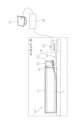
- FIG. 1 is a schematic diagram showing a state in which a sensor is set on a flask in an incubator using a sensor clip according to an embodiment of the present invention, and the sensor is connected to a measuring device via a contact clip.
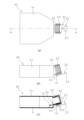
- (a) is a top view of the flask with the sensor attached via the sensor clip in Fig. 1
- (b) is a side view of (a)
- (c) is a cross-sectional view taken along line AA of (a).
- FIG. 3 is an enlarged view showing the sensor attached to the opening of the flask in FIG. 2(c) using a sensor clip.
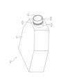
- FIG. 2 is a perspective view showing the configuration of a flask to which a sensor is attached via the sensor clip of FIG. 1.
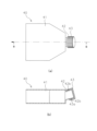
- FIG. 5A is a top view showing a state in which a cap is attached to the opening of the flask in FIG. 4, and FIG. 5B is a cross-sectional view taken along line BB in FIG. 2 is a perspective view showing a configuration of a sensor unit including the sensor clip and a sensor shown in FIG. 1 etc.; 7 is a top view showing the sensor included in the sensor unit of FIG. 6 in a state before the protective part is folded back. 8 is a perspective view showing a state in which a protective portion included in the sensor of FIG. 7 is folded back.
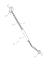
- FIG. 9 is a perspective view showing the configuration of a sensor clip for attaching the sensor of FIG. 8 etc. to the opening of a flask.
- a sensor clip (sensor mounting member) 10 according to one embodiment of the present invention and a sensor unit 30 including the same will be described below with reference to FIGS. 1 to 9.
- FIG. 1 more detailed explanation than necessary may be omitted.
- detailed explanation of already well-known matters or duplicate explanation of substantially the same configuration may be omitted. This is to avoid the following explanation from becoming unnecessarily redundant and to facilitate understanding by those skilled in the art.
- the applicant provides the accompanying drawings and the following description so that those skilled in the art can fully understand the present invention, and they are not intended to limit the subject matter described in the claims.
- the sensor unit 30 As shown in FIG. 1 , the sensor unit 30 according to this embodiment is placed in a flask (container) 40 placed on a shelf of an incubator and has one end immersed in the culture medium X for cell culture.
- the sensor 20 detects components contained in the culture medium X, and a sensor clip 10 for attaching the sensor 20 to an opening 42 of the flask (container) 40.
- one end of the sensor 20 of the sensor unit 30 is immersed in the culture medium X stored inside the flask 40, and the other end is connected to the measuring device 60 via a contact clip (sensor connecting member) 50 provided on the outside of the flask 40.
- the measuring device 60 is, for example, a device that detects various components contained in the culture medium X using a sensor 20 , and is controlled by a PC (Personal Computer) 61 .
- the sensor clip 10 is used in a state where it is engaged with the bottom of the opening 42 in order to attach the sensor 20 to the opening 42 of the flask 40.
- the detailed configuration of the sensor clip 10 will be described later.
- the sensor 20 is attached to the opening 42 of the flask 40 by the sensor clip 10, and is installed so as to be drawn from inside the main body 41 of the flask 40 to the outside through the opening 42.
- the senor 20 is arranged so that an end (first end) 22 including the electrode 22a is arranged inside the flask 40, and an end (second end) 23 including a contact 23a (see Figure 6, etc.) connected to the electrode 22a via a wiring portion 24 is drawn to the outside of the flask 40.
- the flask 40 has an opening 42 to which the sensor 20 is attached using the sensor clip 10 , and a cap 43 can be attached to the opening 42 .
- the opening 42 can be covered with the cap 43 to prevent leakage of the culture medium X, etc.
- the cap 43 can be removed and the culture medium X can be replaced using a tool such as a dropper through the opening 42 with the sensor 20 still attached. The detailed configuration of the sensor 20 will be described later.
- the flask (container) 40 is a container for storing culture medium X for cell culture, and as shown in FIG. 4, is a roughly rectangular container having a main body 41, an opening 42, and a cap 43.
- the main body 41 is a substantially rectangular housing portion in which the culture medium X is stored and which has an opening 42 on one of its end faces.
- the opening 42 is a generally cylindrical portion provided on an end face of the generally rectangular main body 41, which connects the inside and outside of the main body 41, and is provided obliquely upward from the inside to the outside of the main body 41.
- the opening 42 has a screw thread (second screw portion) 42a and a flat portion 42b on its outer circumferential surface.
- the screw thread (second screw portion) 42 a is provided on the outer circumferential surface of the substantially cylindrical opening 42 , and screws into the screw thread (first screw portion) 43 a on the cap 43 side.
- the flat portions 42b are provided on the upper and lower portions of the outer circumferential surface of the substantially cylindrical opening 42, and are flat surface portions where the threads 42a are partially interrupted. The portion of the sensor 20 that is covered by the protective portion 25 when the sensor 20 is attached to the opening 42 of the flask 40 by the sensor clip 10 is disposed on the flat portions 42b (see Fig. 2(c)).
- the cap 43 is a cylindrical lid member with a bottom that closes the opening 42, and as shown in FIG. 5(b), has a screw thread (first screw portion) 43a on its inner circumferential surface. As shown in Figure 5 (b), the screw thread (first screw portion) 43a is provided on the inner surface of the cylindrical cap 43, and by screwing into the screw thread 42a (see Figure 4) on the opening 42 side, the opening 42 is closed by the cap 43.
- the sensor 20 is included in a sensor unit 30, and is attached to an opening 42 of a flask 40 while being held by a sensor clip 10. As shown in Fig. 7, the sensor 20 has an end (first end) 22, an end (second end) 23, a main body portion 21 connecting the ends 22, 23, a wiring portion 24, and a protective portion 25.
- the main body 21 is, for example, a thin plate-like member molded from PET (polyethylene terephthalate) resin, and has an end 22 including an electrode 22a at one end in the longitudinal direction and an end 23 including a contact 23a at the other end as shown in Fig. 7.
- a protective portion 25 is provided so as to protrude in a direction intersecting the longitudinal direction of the main body 21.
- an electrode 22a is provided at the end (first end) 22, which is inserted into the flask 40. The end 22 is disposed so that the electrode 22a is immersed in the culture medium X stored in the flask 40.
- the end (second end) 23 is provided with a contact 23a to be connected to a measuring device 60 installed outside the flask 40.
- the end 23 has the contact 23a connected to the measuring device 60 installed outside the incubator via a contact clip 50 (see FIG. 1).
- the wiring portion 24 is provided along the upper surface of the main body portion 21 from the end portion 22 to the end portion 23, and electrically connects the electrode 22a and the contact point 23a.
- the protective portion 25, like the main body portion 21, is a thin plate-like member molded from PET resin, and is connected to the main body portion 21 in a direction intersecting the longitudinal direction.
- the protective portion 25 is folded back from the main body portion 21 in the direction of the arrow shown in FIG. 7 at a fold line 25a provided at the connection portion with the main body portion 21, thereby covering a portion of the wiring portion 24 provided on the upper surface of the main body portion 21, as shown in FIG. 8.
- the portion of the wiring portion 24 covered by the protective portion 25 shown in Figure 8 is positioned on the outer peripheral surface of the opening 42 when the sensor 20 is attached to the opening 42 of the flask 40 shown in Figure 3 etc.
- the protective portion 25 can prevent the wiring portion 24 of the sensor 20 from being damaged, for example, by the threads 43a provided on the inner surface of the cap 43.
- Sensor clip (sensor mounting member) 10 is formed, for example, by sheet metal processing a stainless steel plate member, and as shown in Fig. 3 etc., the sensor clip 10 is attached to an opening 42 of a flask 40 while holding the sensor 20.
- the sensor clip 10 includes a mounting portion 11, a holding portion 12, a bending portion 13, a gripping portion 14, and a silicone tube (buffer member) 15.
- the mounting portion 11 is a long, thin plate-like portion on whose upper surface the sensor 20 is placed. As shown in FIG. 9, the mounting portion 11 has an end 11b connected to one end and a bent portion 13 and a gripping portion 14 connected to the other end. In addition, as shown in FIG. 9, a notch 11a is provided between the mounting portion 11 and the end 11b, which is formed by cutting out a part of the mounting portion 11.
- the cutout portion 11a is provided by cutting out a part of the mounting portion 11, and passes the end portion 22 including the electrode 22a of the sensor 20 mounted on the upper surface of the mounting portion 11 to the rear surface of the mounting portion 11.
- the end portion 22 including the electrode 22a of the sensor 20 is guided from the upper surface side to the rear surface side of the mounting portion 11 and is immersed in the culture medium X stored in the flask 40.
- the end portion 11b is connected to the mounting portion 11 so as to sandwich the notch portion 11a on the same plane as the mounting portion 11. More specifically, the end portion 11b is connected to the mounting portion 11 by a narrow portion excluding the portion where the notch portion 11a is provided.
- the holding portion 12 is provided in a direction intersecting the longitudinal direction of the mounting portion 11, and holds the body portion 21 of the sensor 20 along the longitudinal direction on the upper surface of the mounting portion 11 (see FIG. 6).
- the holding portion 12 has a plurality of fold-back pieces 12a that are folded back with respect to the mounting portion 11 in a direction intersecting the longitudinal direction of the sensor 20.
- the multiple folded pieces 12a are provided alternately on both the left and right sides in the longitudinal direction of the sensor 20. This makes it possible to reliably hold the sensor 20 from both sides on the upper surface of the mounting portion 11 using the multiple folded pieces 12a, as shown in Fig. 6 and other figures.
- the bent portion 13 is connected to the mounting portion 11, is bent so as to be disposed along the inner peripheral surface to the outer peripheral surface of the opening 42 of the flask 40, and is engaged with the opening 42 of the flask 40.
- the bent portion 13 is attached to the opening 42 so as to sandwich the inner peripheral surface and the outer peripheral surface of the opening 42 of the flask 40 (see FIG. 2(c)). This allows the sensor clip 10 to be easily attached to the opening 42 of the flask 40 while holding the sensor 20 .
- the gripping part 14 is provided at the end of the bent part 13 opposite to the end connected to the mounting part 11.
- the gripping part 14 is gripped by the fingers of the user when attaching the sensor 20 attached to the opening 42 of the flask 40.
- the sensor clip 10 is attached to the opening 42 of the flask 40 while holding the sensor 20
- the sensor clip 10 is attached while holding the gripping portion 14, which is provided at a position as far away as possible from the bent portion 13 that engages with the opening 42. This prevents the user's fingers from accidentally touching the area near the opening 42, and suppresses the occurrence of contamination inside the flask 40 via the opening 42.
- the grip portion 14 has a tapered surface 14a bent at a predetermined angle with respect to the upper surface of the grip portion 14 that is connected to the bent portion 13.
- the tapered surface 14a guides the end 23 including the contact 23a so that the sensor 20, which is pulled out of the flask 40 through the opening 42, is folded along the bent portion 13 and then folded back toward the measuring device 60.
- the silicon tube (shock absorber) 15 is, for example, a shock absorber made of silicon resin, and is attached so as to cover the contact portion with the wiring portion 24 of the sensor 20 at the end portion 11b as shown in FIG. This makes it possible to prevent the wiring portion 24 of the sensor 20, which passes through the cutout portion 11a and is led from the upper surface of the mounting portion 11 to the rear surface side, from coming into contact with the end portion 11b and being damaged.
- the sensor clip 10 of this embodiment is a member for attaching the sensor 20, which is used in a state inserted inside the flask 40, to the opening 42, and includes a mounting portion 11 and a bent portion 13.
- the sensor 20 has an end portion 22 including an electrode 22a inserted inside the flask 40, an end portion 23 including a contact 23a connected to a measuring device 60 installed outside the flask 40, a main body portion 21 connecting the ends 22, 23, and a wiring portion 24 provided on the main body portion 21 and electrically connecting the electrode 22a and the contact 23a.
- the main body portion 21 of the sensor 20 is mounted on the mounting portion 11.
- the bent portion 13 is connected to the mounting portion 11, and is bent so as to be disposed along the inner peripheral surface of the opening 42 from the outer peripheral surface, and is engaged with the opening 42 of the flask 40.
- the sensor 20 to be attached to the opening 42 of the flask 40 by attaching the bent portion to the opening 42 of the flask 40 while leaving the opening 42 open.
- the culture medium X can be replaced or the like while the sensor 20 is attached to the opening 42 of the flask 40, thereby improving ease of use.
- the present invention is not limited to the above embodiment, and various modifications are possible without departing from the gist of the invention.
- the sensor clip 10 is used to attach the sensor 20, which is used with the end 22 including the electrode 22a immersed in the culture medium X for cell culture, to a container such as a flask 40.
- the present invention is not limited to this.
- the sensor attachment member is not limited to sensors used in cell culture, and may be used to attach various sensors to a container.
- the holding portion may have any configuration as long as it can fix the main body of the sensor to the placement portion.
- the back surface of the sensor and the mounting portion may be fixed and held using a double-sided adhesive tape.
- the sensor and the mounting portion may be joined together using tape and then wrapped around the outer periphery to hold them.
- the sensor and the mounting portion may be sandwiched and held using a means such as a general clip.
- the sensor and the mounting portion may be joined together and then sandwiched between two plate-like members, and the two plate-like members may be fixed together using a fastening member such as a screw to hold them.
- a sensor may be attached via a sensor attachment member to the opening of a container that does not use a cap.
- the present invention is not limited to this.
- the sensor may be attached via a sensor attachment member to an opening having a screw thread provided on the entire outer circumferential surface in the circumferential direction.
- a cap with an inner diameter slightly larger than normal may be prepared and attached.
- Sensor clip (sensor mounting member) 11: Placement portion 11a; Notch portion 11b; End portion 12: Holding portion 12a; Folded piece 13: Bending portion 14: Grip portion 14a; Tapered surface 15: Silicon tube (cushion member) 20: Sensor 21: Main body 22: End (first end) 22a electrode 23 end (second end) 23a Contact 24 Wiring portion 25 Protective portion 25a Fold-back line 30 Sensor unit 40 Flask (container) 41 Main body portion 42 Opening 42a Screw thread (second screw portion) 42b Flat portion 43 Cap 43a Thread (first thread portion) 50 Contact clip (sensor connecting member) 60 Measuring device 61 PC X medium
Landscapes
- Chemical & Material Sciences (AREA)
- Health & Medical Sciences (AREA)
- Life Sciences & Earth Sciences (AREA)
- Engineering & Computer Science (AREA)
- Bioinformatics & Cheminformatics (AREA)
- Organic Chemistry (AREA)
- Biotechnology (AREA)
- Zoology (AREA)
- Wood Science & Technology (AREA)
- Sustainable Development (AREA)
- Microbiology (AREA)
- Biomedical Technology (AREA)
- Medicinal Chemistry (AREA)
- Biochemistry (AREA)
- General Engineering & Computer Science (AREA)
- General Health & Medical Sciences (AREA)
- Genetics & Genomics (AREA)
- Analytical Chemistry (AREA)
- Physics & Mathematics (AREA)
- General Physics & Mathematics (AREA)
- Apparatus Associated With Microorganisms And Enzymes (AREA)
Abstract
Priority Applications (3)
| Application Number | Priority Date | Filing Date | Title |
|---|---|---|---|
| JP2025541352A JPWO2025041509A1 (fr) | 2023-08-24 | 2024-07-23 | |
| EP24856203.5A EP4711441A1 (fr) | 2023-08-24 | 2024-07-23 | Élément de fixation de capteur et unité de capteur qui en est pourvue |
| US19/415,419 US20260110560A1 (en) | 2023-08-24 | 2025-12-10 | Sensor attachment member and sensor unit provided with same |
Applications Claiming Priority (2)
| Application Number | Priority Date | Filing Date | Title |
|---|---|---|---|
| JP2023136079 | 2023-08-24 | ||
| JP2023-136079 | 2023-08-24 |
Related Child Applications (1)
| Application Number | Title | Priority Date | Filing Date |
|---|---|---|---|
| US19/415,419 Continuation US20260110560A1 (en) | 2023-08-24 | 2025-12-10 | Sensor attachment member and sensor unit provided with same |
Publications (1)
| Publication Number | Publication Date |
|---|---|
| WO2025041509A1 true WO2025041509A1 (fr) | 2025-02-27 |
Family
ID=94731708
Family Applications (1)
| Application Number | Title | Priority Date | Filing Date |
|---|---|---|---|
| PCT/JP2024/026269 Pending WO2025041509A1 (fr) | 2023-08-24 | 2024-07-23 | Élément de fixation de capteur et unité de capteur qui en est pourvue |
Country Status (4)
| Country | Link |
|---|---|
| US (1) | US20260110560A1 (fr) |
| EP (1) | EP4711441A1 (fr) |
| JP (1) | JPWO2025041509A1 (fr) |
| WO (1) | WO2025041509A1 (fr) |
Citations (5)
| Publication number | Priority date | Publication date | Assignee | Title |
|---|---|---|---|---|
| JP2009133713A (ja) * | 2007-11-30 | 2009-06-18 | Fuji Electric Systems Co Ltd | 酸素センサの電極活性化処理方法、および、電極活性化処理装置 |
| JP2021006022A (ja) | 2019-06-27 | 2021-01-21 | ショット アクチエンゲゼルシャフトSchott AG | バイオプロセスコントロールのためのマルチセンサコンポーネント |
| JP2021065124A (ja) * | 2019-10-21 | 2021-04-30 | Phcホールディングス株式会社 | センサユニットおよびこれを備えた細胞培養分析装置 |
| JP2022038190A (ja) * | 2020-08-26 | 2022-03-10 | Phcホールディングス株式会社 | センサモジュール |
| JP2022089378A (ja) * | 2020-12-04 | 2022-06-16 | 株式会社Soken | ガス濃度検出装置 |
-
2024
- 2024-07-23 EP EP24856203.5A patent/EP4711441A1/fr active Pending
- 2024-07-23 JP JP2025541352A patent/JPWO2025041509A1/ja active Pending
- 2024-07-23 WO PCT/JP2024/026269 patent/WO2025041509A1/fr active Pending
-
2025
- 2025-12-10 US US19/415,419 patent/US20260110560A1/en active Pending
Patent Citations (5)
| Publication number | Priority date | Publication date | Assignee | Title |
|---|---|---|---|---|
| JP2009133713A (ja) * | 2007-11-30 | 2009-06-18 | Fuji Electric Systems Co Ltd | 酸素センサの電極活性化処理方法、および、電極活性化処理装置 |
| JP2021006022A (ja) | 2019-06-27 | 2021-01-21 | ショット アクチエンゲゼルシャフトSchott AG | バイオプロセスコントロールのためのマルチセンサコンポーネント |
| JP2021065124A (ja) * | 2019-10-21 | 2021-04-30 | Phcホールディングス株式会社 | センサユニットおよびこれを備えた細胞培養分析装置 |
| JP2022038190A (ja) * | 2020-08-26 | 2022-03-10 | Phcホールディングス株式会社 | センサモジュール |
| JP2022089378A (ja) * | 2020-12-04 | 2022-06-16 | 株式会社Soken | ガス濃度検出装置 |
Also Published As
| Publication number | Publication date |
|---|---|
| JPWO2025041509A1 (fr) | 2025-02-27 |
| US20260110560A1 (en) | 2026-04-23 |
| EP4711441A1 (fr) | 2026-03-18 |
Similar Documents
| Publication | Publication Date | Title |
|---|---|---|
| US8394343B2 (en) | Integrated test strip container with retaining insert | |
| RU2531896C1 (ru) | Влагонепроницаемый контейнер | |
| US8697014B2 (en) | Specimen rack | |
| JP5255052B2 (ja) | 質量感知化学センサ | |
| JP6441965B2 (ja) | 互換性のある試験エレメント保持装置 | |
| CN101720216A (zh) | 试剂容器 | |
| EP3356546B1 (fr) | Systèmes pour un support de bande de test d'écoulement latéral | |
| WO2025041509A1 (fr) | Élément de fixation de capteur et unité de capteur qui en est pourvue | |
| US20180024073A1 (en) | Reach-extended test strip | |
| RU2556735C2 (ru) | Упаковка для манипулирования кюветами | |
| KR101987714B1 (ko) | 나사식 밀폐형 뚜껑을 적용한 감마선분광분석용 마리넬리 비이커 | |
| US20190049427A1 (en) | Portable diagnostic measurement device for determining analytical parameter of body fluid | |
| EP1457261A2 (fr) | Procédé et dispositif pour le transport de tubes sous vide de prélèvement de sang | |
| US11085894B2 (en) | Sensor apparatus with liquid container and wiper | |
| JP4897402B2 (ja) | 検体容器用アダプタ、及び検体容器用ラック | |
| CN210005535U (zh) | 反应容器 | |
| CN217505896U (zh) | 样本分析仪及适配器 | |
| US9429206B2 (en) | Sensor mounting attachment | |
| JP4829624B2 (ja) | 試薬容器用蓋体及びそれを装着した試薬容器、試薬キット | |
| US10107775B2 (en) | Organism sample measurement sensor and housing container that houses same | |
| CN216036159U (zh) | 一种适用于玻璃量具安全运输或携带的存放装置 | |
| EP3205994A1 (fr) | Sonde de pression et appareil | |
| CN220715892U (zh) | 一种化验杯 | |
| WO2018181646A1 (fr) | Adaptateur de récipient pour réactif | |
| US12343167B2 (en) | Measuring device with wrinkle suppression |
Legal Events
| Date | Code | Title | Description |
|---|---|---|---|
| 121 | Ep: the epo has been informed by wipo that ep was designated in this application |
Ref document number: 24856203 Country of ref document: EP Kind code of ref document: A1 |
|
| ENP | Entry into the national phase |
Ref document number: 2025541352 Country of ref document: JP Kind code of ref document: A |
|
| WWE | Wipo information: entry into national phase |
Ref document number: 2025541352 Country of ref document: JP |
|
| WWE | Wipo information: entry into national phase |
Ref document number: 2024856203 Country of ref document: EP |
|
| ENP | Entry into the national phase |
Ref document number: 2024856203 Country of ref document: EP Effective date: 20251208 |
|
| ENP | Entry into the national phase |
Ref document number: 2024856203 Country of ref document: EP Effective date: 20251208 |
|
| ENP | Entry into the national phase |
Ref document number: 2024856203 Country of ref document: EP Effective date: 20251208 |
|
| ENP | Entry into the national phase |
Ref document number: 2024856203 Country of ref document: EP Effective date: 20251208 |
|
| ENP | Entry into the national phase |
Ref document number: 2024856203 Country of ref document: EP Effective date: 20251208 |
|
| ENP | Entry into the national phase |
Ref document number: 2024856203 Country of ref document: EP Effective date: 20251208 |
|
| ENP | Entry into the national phase |
Ref document number: 2024856203 Country of ref document: EP Effective date: 20251208 |
|
| ENP | Entry into the national phase |
Ref document number: 2024856203 Country of ref document: EP Effective date: 20251208 |
|
| ENP | Entry into the national phase |
Ref document number: 2024856203 Country of ref document: EP Effective date: 20251208 |
|
| WWP | Wipo information: published in national office |
Ref document number: 2024856203 Country of ref document: EP |
|
| NENP | Non-entry into the national phase |
Ref country code: DE |