WO2025046676A1 - Climatiseur - Google Patents
Climatiseur Download PDFInfo
- Publication number
- WO2025046676A1 WO2025046676A1 PCT/JP2023/030841 JP2023030841W WO2025046676A1 WO 2025046676 A1 WO2025046676 A1 WO 2025046676A1 JP 2023030841 W JP2023030841 W JP 2023030841W WO 2025046676 A1 WO2025046676 A1 WO 2025046676A1
- Authority
- WO
- WIPO (PCT)
- Prior art keywords
- unit
- compressor
- rotation speed
- air conditioner
- determination
- Prior art date
- Legal status (The legal status is an assumption and is not a legal conclusion. Google has not performed a legal analysis and makes no representation as to the accuracy of the status listed.)
- Pending
Links
Images



Classifications
-
- F—MECHANICAL ENGINEERING; LIGHTING; HEATING; WEAPONS; BLASTING
- F24—HEATING; RANGES; VENTILATING
- F24F—AIR-CONDITIONING; AIR-HUMIDIFICATION; VENTILATION; USE OF AIR CURRENTS FOR SCREENING
- F24F11/00—Control or safety arrangements
- F24F11/30—Control or safety arrangements for purposes related to the operation of the system, e.g. for safety or monitoring
- F24F11/49—Control or safety arrangements for purposes related to the operation of the system, e.g. for safety or monitoring ensuring correct operation, e.g. by trial operation or configuration checks
-
- F—MECHANICAL ENGINEERING; LIGHTING; HEATING; WEAPONS; BLASTING
- F24—HEATING; RANGES; VENTILATING
- F24F—AIR-CONDITIONING; AIR-HUMIDIFICATION; VENTILATION; USE OF AIR CURRENTS FOR SCREENING
- F24F2110/00—Control inputs relating to air properties
- F24F2110/10—Temperature
-
- F—MECHANICAL ENGINEERING; LIGHTING; HEATING; WEAPONS; BLASTING
- F24—HEATING; RANGES; VENTILATING
- F24F—AIR-CONDITIONING; AIR-HUMIDIFICATION; VENTILATION; USE OF AIR CURRENTS FOR SCREENING
- F24F2110/00—Control inputs relating to air properties
- F24F2110/10—Temperature
- F24F2110/12—Temperature of the outside air
-
- F—MECHANICAL ENGINEERING; LIGHTING; HEATING; WEAPONS; BLASTING
- F24—HEATING; RANGES; VENTILATING
- F24F—AIR-CONDITIONING; AIR-HUMIDIFICATION; VENTILATION; USE OF AIR CURRENTS FOR SCREENING
- F24F2110/00—Control inputs relating to air properties
- F24F2110/20—Humidity
Definitions
- This disclosure relates to air conditioners.
- air conditioners have been known that have a function for test-running the air conditioner after installation work is completed to determine whether the operating valve is in a closed state and to inform the installer whether there have been any construction errors.
- Patent Document 1 discloses an air conditioner that includes a liquid pipe temperature sensor that detects the temperature of a liquid pipe connected to an indoor heat exchanger, and a gas pipe temperature sensor that detects the temperature of a gas pipe connected to the indoor heat exchanger, and that calculates the difference in temperatures detected by the liquid pipe temperature sensor and the gas pipe temperature sensor to determine the open/closed state of an operating valve provided in a connecting pipe that connects an outdoor unit and an indoor unit.
- the objective of this disclosure is to provide an air conditioner that can improve the accuracy of determining whether an operating valve is closed.
- the air conditioner of the present disclosure comprises: A plurality of indoor units each having an indoor heat exchanger; an outdoor unit having a compressor; a plurality of operation valves that open and close the flow of refrigerant between the plurality of indoor units and the outdoor unit; A rotation speed detection unit that detects the rotation speed of the compressor; a temperature difference detection unit that detects a temperature difference between the temperature of the indoor heat exchanger and the temperature of a room in which the indoor heat exchanger is installed; a determination unit that determines that the control valve is in a closed state when the rotation speed detected by the rotation speed detection unit is equal to or greater than a reference value and the temperature difference detected by the temperature difference detection unit is smaller than a close determination value,
- the reference value is a threshold value for the rated rotation speed of the compressor, which is determined by the total capacity of the indoor units that are in operation.
- FIG. 2 is a control block diagram of the air conditioner according to the embodiment;
- FIG. 11 is a flowchart showing an example of a state determination of an operating valve by a determination unit.
- FIG. 11 is a flowchart showing another example of the state determination of the control valve by the determination unit.
- FIG. 1 is a diagram showing the refrigerant circuit configuration of the air conditioner 100 according to one embodiment.
- the air conditioner 100 is a multi-type air conditioner.
- the air conditioner 100 is equipped with multiple indoor units A, B and an outdoor unit C.
- two indoor units A, B are provided for one outdoor unit C, but this is not limited to this.
- three or more indoor units may be provided for one outdoor unit C.
- the indoor unit A may be installed in the same room as the other indoor unit B, or may be installed in a different room from the other indoor unit B.
- the air conditioner 100 is equipped with gas side pipes 10a and 10b and liquid side pipes 11a and 11b.
- the air conditioner 100 is equipped with a gas side operating valve 3a connected to the gas side pipe 10a, a gas side operating valve 3b connected to the gas side pipe 10b, a liquid side operating valve 6a connected to the liquid side pipe 11a, and a liquid side operating valve 6b connected to the liquid side pipe 11b.
- Operating valves 3a to 6b (also called “service valves 3a to 6b") open and close the flow of refrigerant between indoor units A, B and outdoor unit C.
- Operating valves 3a to 6b are manually operated valves that are used in the closed state when installing the air conditioner 100, for operational inspections, maintenance, etc., and are normally used in the open state after installation.
- the indoor unit A includes an indoor heat exchanger 4a, an indoor fan 5a, an indoor heat exchanger temperature sensor 12a, and a room temperature sensor 13a.
- the indoor unit A may further include a humidity sensor 17a.
- the humidity sensor 17a may be provided inside the indoor unit A, or may be provided outside the indoor unit A (for example, in the room in which the indoor unit A is installed).
- the volume of the indoor heat exchanger 4a is set appropriately according to the capacity of the indoor unit A desired by the user.
- the volume of the indoor heat exchanger 4a may be the same as the volume of the other indoor heat exchangers 4b, or may be different from the volume of the other indoor heat exchangers 4b.
- the indoor heat exchanger 4a is equipped with a refrigerant pipe (not shown) through which the refrigerant flows, and a number of fins for exchanging heat between the refrigerant flowing through the refrigerant pipe and the indoor air.
- the indoor fan 5a ventilates the indoor air through the indoor heat exchanger 4a (between the fins) to exchange heat and cool or heat the indoor air.
- the indoor heat exchanger temperature sensor 12a measures the temperature of the indoor heat exchanger 4a.
- the indoor heat exchanger temperature sensor 12a is, for example, a thermistor, and is attached to the indoor heat exchanger 4a.
- the indoor heat exchanger temperature sensor 12a is preferably installed (attached) to the heat transfer tube of the indoor heat exchanger 4a.
- the indoor heat exchanger temperature sensor 12a is installed, for example, at the folded-back portion of the heat transfer tube.
- the room temperature sensor 13a measures the temperature of the indoor air, specifically, the air temperature on the intake side of the indoor heat exchanger 4a.
- the room temperature sensor 13a may be provided inside the indoor unit A, or may be provided outside the indoor unit A (for example, in the room in which the indoor unit A is installed).
- the room temperature sensor 13a may be the same as the indoor heat exchanger temperature sensor 12a, or may be different.
- the outdoor unit C includes a compressor 1, a four-way valve 2, electric expansion valves 7a and 7b, an outdoor heat exchanger 8, an outdoor fan 9, and an outdoor air temperature sensor 22.
- the compressor 1 includes a motor (not shown) whose rotation speed is variable.
- Four-way valve 2 switches whether the gas refrigerant discharged from compressor 1 is directed to outdoor heat exchanger 8 or to indoor units A and B. In other words, four-way valve 2 switches between cooling operation and heating operation.
- the solid lines in Figure 1 indicate the four-way valve 2 in heating operation, and the dashed lines in Figure 1 indicate the four-way valve 2 in cooling operation.
- the motorized expansion valve 7a is provided in the liquid side pipe 11a, and the motorized expansion valve 7b is provided in the liquid side pipe 11b.
- the gas side operating valve 3a, the indoor heat exchanger 4a, the liquid side operating valve 6a, and the motorized expansion valve 7a are connected in series, and the gas side operating valve 3b, the indoor heat exchanger 4b, the liquid side operating valve 6b, and the motorized expansion valve 7b are connected in series, and both series refrigerant circuits are connected in parallel.
- the outdoor heat exchanger 8 is equipped with a refrigerant pipe (not shown) through which the refrigerant flows, and a number of fins for exchanging heat between the refrigerant flowing through the refrigerant pipe and outdoor air (outdoor air).
- the outdoor fan 9 ventilates the outdoor air through the outdoor heat exchanger 8 (between the fins) to exchange heat and cool or heat the refrigerant.
- the outdoor air temperature sensor 22 measures the temperature outside the room.
- the outdoor air temperature sensor 22 may be provided inside the outdoor unit C or outside the outdoor unit C.
- the outdoor air temperature sensor 22 may be the same as the indoor heat exchanger temperature sensor 12a or the room temperature sensor 13a, or may be different from them.
- the refrigerant compressed by the compressor 1 flows through the four-way valve 2 as a high-temperature, high-pressure gas refrigerant into each indoor heat exchanger 4a, 4b, and becomes a high-pressure liquid refrigerant by dissipating heat to the air sent by the indoor fans 5a, 5b. This allows the warmed air to flow into the room, providing indoor heating.
- the high-pressure liquid refrigerant is then reduced in pressure by passing through each electric expansion valve 7a, 7b, and becomes a low-temperature, low-pressure, gas-liquid two-phase state. It then flows into the outdoor heat exchanger 8, where it absorbs heat from the air (outdoor air) sent by the outdoor fan 9, evaporating and becoming a gas refrigerant.
- This gas refrigerant returns to the compressor 1 via the four-way valve 2 and is compressed again. This is the refrigeration cycle during heating operation.
- the refrigerant compressed by the compressor 1 passes through the four-way valve 2 as a high-temperature, high-pressure gas refrigerant and flows into the outdoor heat exchanger 8, where it condenses by releasing heat to the air (outdoor air) sent by the outdoor fan 9, becoming a high-pressure liquid refrigerant.
- the high-pressure liquid refrigerant is then reduced in pressure by passing through each of the electric expansion valves 7a, 7b, becoming a low-temperature, low-pressure, gas-liquid two-phase state, and flows into the indoor heat exchangers 4a, 4b, where it evaporates by absorbing heat from the air sent by the indoor fans 5a, 5b, thereby achieving indoor cooling.
- the gas refrigerant evaporated in the indoor heat exchangers 4a, 4b returns to the compressor 1 via the four-way valve 2 and is compressed again. This is the refrigeration cycle during cooling operation.
- the outdoor unit C When the air conditioner 100 is shipped from the factory, the outdoor unit C is separated from the indoor units A and B. Refrigerant is sealed in the refrigerant circuit on the outdoor unit C side, and the gas side operating valves 3a and 3b and the liquid side operating valves 6a and 6b are closed.
- the installation work for this factory-shipped air conditioner 100 involves first installing the outdoor unit C and indoor units A and B in the designated locations, then connecting the gas side piping 10a and liquid side piping 11a connected to indoor unit A to the gas side operating valve 3a and liquid side operating valve 6a, respectively. Then, the vacuum pump connected to the gas side operating valve 3a is operated to create a vacuum, and the vacuum pump is then removed. After that, by fully opening the liquid side operating valve 6a and the gas side operating valve 3a, the refrigerant sealed in the refrigerant circuit of outdoor unit C flows into the refrigerant circuit of indoor unit A, and the work on indoor unit A is completed. The same work is performed for indoor unit B, and the installation work for the air conditioner 100 is completed.
- the temperature difference between the operating temperature of the indoor heat exchanger 4a and the room temperature becomes large.
- the air conditioner 100 is operated when both the gas side operating valve 3a and the liquid side operating valve 6a are closed due to an installation error, the refrigerant does not circulate through the indoor heat exchanger 4a, and the temperature difference does not become large as in normal operation described above.
- the compressor 1 may become overloaded, causing its temperature to rise abnormally, which may lead to damage to the compressor 1. Therefore, the configuration described below is used to determine whether the operating valves 3a and 6a are in a closed state (a similar determination can be made for the operating valves 3b and 6b).
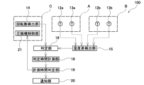
- the air conditioner 100 is equipped with a rotation speed detection unit 14 that detects the rotation speed of the compressor 1, a temperature difference detection unit 15 that detects the temperature difference between the temperature of the indoor heat exchangers 4a, 4b after they are in operation and the temperature (room temperature) of the room in which they are installed, and a determination unit 16 that determines whether at least the operating valves 3a to 6b are in a closed state.
- FIG. 2 is a control block diagram of the air conditioner 100.
- the rotation speed detection unit 14 detects the rotation speed of the motor of the compressor 1.
- the rotation speed detection unit 14 may directly detect the rotation speed of the motor, for example, using an encoder attached to the drive shaft of the motor, or may detect the rotation speed of the motor from the drive current supplied to the motor.
- the rotation speed of the compressor 1 refers to the rotation speed of the motor.
- the temperature difference detection unit 15 detects the temperature difference between the temperature of the indoor heat exchanger 4a measured by the indoor heat exchanger temperature sensor 12a and the room temperature (room temperature) measured by the room temperature sensor 13a.
- the temperature difference detection unit 15 also detects the temperature difference between the temperature of the indoor heat exchanger 4b measured by the indoor heat exchanger temperature sensor 12b and the room temperature (room temperature) measured by the room temperature sensor 13b.
- one temperature difference detection unit 15 is provided for one air conditioner 100, and one temperature difference detection unit 15 detects the temperature difference in each indoor unit A, B, but this is not limited to this.
- the temperature difference detection unit 15 may be provided in each indoor unit A, B, and the temperature difference in each indoor unit A, B may be detected by the temperature difference detection unit provided in each indoor unit A, B.
- the temperature difference is calculated, for example, by room temperature minus the temperature of the indoor heat exchanger during cooling operation, and by the temperature of the indoor heat exchanger minus room temperature during heating operation.
- the judgment unit 16 judges that the operating valves 3a, 6a are in the closed state when the rotation speed of the compressor 1 detected by the rotation speed detection unit 14 is equal to or greater than a reference value and the temperature difference detected by the temperature difference detection unit 15 is smaller than the closed judgment value.
- the judgment unit 16 can suppress erroneous judgments that the operating valves 3a, 6a are in the closed state. For example, when multiple indoor units A and B are operated when the rotation speed of the compressor 1 is lower than the reference value, the amount of refrigerant circulating through the refrigerant circuit of indoor unit A is small, so the temperature difference between the temperature of the indoor heat exchanger 4a and the room temperature is small. In other words, the temperature difference between the open and closed states of the operating valves 3a and 6a is small, making it difficult to determine the closed state of the operating valves 3a and 6a. This allows the judgment unit 16 to improve the accuracy of judging the closed state of the operating valves 3a and 6a. The judgment unit 16 also judges the operating valves 3b and 6b in the same manner as above (same below).
- the close judgment value (also called the “close judgment temperature difference”) can be set appropriately depending on the combination of the indoor units A, B and the outdoor unit C.
- the close judgment value is, for example, 5°C.
- the reference value (also called the "reference speed”) is a threshold value for the speed of the compressor 1. Since the total capacity changes depending on the combination and number of indoor units, if the threshold value for the speed of the compressor 1 is specified as an absolute value, for example, if the threshold value is too low, the control valves 3a and 6a may be erroneously determined to be closed even though they are open due to a lack of refrigerant circulation. Also, if the threshold value for the speed of the compressor 1 is too high, the speed of the compressor 1 may not reach the reference value during operation, and the control valves 3a and 6a may not be determined in the first place.
- the threshold value for the speed of the compressor 1 is set to the threshold value for the rated speed of the compressor 1, which is determined by the total capacity (kW) of the indoor units A and B that are operating.
- the threshold value is, for example, 90% of the rated speed of the compressor 1.
- the threshold value can also be set appropriately depending on the combination of each indoor unit A, B and the outdoor unit C.
- FIG. 4 is a flow chart showing an example of the state judgment of the control valve by the judgment unit.
- the rotation speed of the compressor is detected (S1). Then, it is confirmed whether the rotation speed is equal to or greater than a reference value (S2). If the rotation speed is equal to or greater than the reference value in S2, the temperature difference between the temperature of the indoor heat exchanger and the room temperature is detected (S3). Then, it is confirmed whether the temperature difference is smaller than the close judgment value (S4). If the temperature difference is smaller than the close judgment value in S4, the judgment unit judges that the control valve is in the closed state (S5).
- S4 If the temperature difference is equal to or greater than the close judgment value in S4, it is confirmed whether the temperature difference is larger than an open judgment value (described later) (S6). Note that, in the flow chart in FIG. 4, it is first confirmed whether the rotation speed is equal to or greater than the reference value (S2), but it is also possible to first confirm whether the temperature difference is smaller than the close judgment value (S4). That is, S3 and S4 may be performed before S1 and S2.
- the judgment unit 16 judges that the control valves 3a, 6a are open (see S6 and S7 in FIG. 4) when the temperature difference between the temperature of the indoor heat exchanger 4a (after operation) and the temperature (room temperature) of the room in which it is installed is greater than the open judgment value.
- the judgment unit 16 does not have to judge whether the control valves 3a, 6a are open.
- the open judgment value may be the same value as the closed judgment value, or may be a value different from the closed judgment value.
- the determination unit 16 preferably determines the state of the control valves 3a, 6a when the rotation speed of the compressor 1 is equal to or higher than the upper limit rotation speed (areas A1, A4 in FIG. 3). With this configuration, by determining that the compressor 1 is in the closed state when the rotation speed of the compressor 1 is equal to or higher than the upper limit rotation speed, the operation of the compressor 1 is stopped, thereby preventing the compressor 1 from being overheated due to an increase in the discharge pressure of the compressor 1 and thus preventing damage to the compressor 1.
- the upper limit rotation speed is the rotation speed at which the discharge pressure of compressor 1 rises and compressor 1 becomes overheated.
- the upper limit rotation speed can be set appropriately depending on the combination of indoor units A, B and outdoor unit C.
- the judgment unit 16 does not judge whether the control valves 3a and 6a are in the closed state even when the temperature difference detected by the temperature difference detection unit 15 is smaller than the closed judgment value.
- the lower limit rotation speed is the rotation speed at which the discharge pressure of compressor 1 does not increase and compressor 1 does not become overheated.
- the lower limit rotation speed can be set appropriately depending on the combination of indoor units A, B and outdoor unit C.
- FIG. 5 is a flowchart showing another example of the state determination of the operating valve by the determination unit. The differences from the flowchart in FIG. 4 will be explained.
- the rotation speed is less than the reference value in S2 and is equal to or greater than the upper determination limit rotation speed (S7), the temperature difference between the temperature of the indoor heat exchanger and the room temperature is detected (S3).
- the rotation speed is equal to or greater than the reference value in S2 and is equal to or less than the lower determination limit rotation speed (S8), the determination unit does not determine the state of the operating valve. If the rotation speed exceeds the lower determination limit rotation speed in S9, the temperature difference between the temperature of the indoor heat exchanger and the room temperature is detected (S3).
- the close judgment value may be set based on the room temperature and humidity during cooling operation.
- the close judgment value may be set for each room in which each indoor unit A, B is installed. The same applies to the open judgment value.
- the room temperature is measured by the room temperature sensor 13a, and the humidity is measured by the humidity sensor 17a.
- the judgment unit 16 sets the close judgment value lower than normal. For example, when the room temperature is 32°C or higher and the humidity is 80% or higher, the judgment unit 16 sets the close judgment value 2°C lower than normal.
- the closed state determination value may be set based on the room temperature and the outside air temperature.
- the closed state determination value is set based on the room temperature and the outside air temperature, which can reduce erroneous determination of the closed state of the control valves 3a, 6a. This is because the refrigeration capacity changes depending on the room temperature and the outside air temperature, and the temperature difference between the temperature of the indoor heat exchanger 4a and the room temperature changes. This can increase the accuracy of determining the closed state of the control valves 3a, 6a.
- the outdoor air temperature is measured by the outdoor air temperature sensor 22.
- the judgment unit 16 sets the close judgment value higher than normal.
- the judgment unit 16 sets the close judgment value 2°C higher than normal. The same applies to the open judgment value.
- the determination unit 16 preferably determines the state (whether it is closed or open) of each of the multiple control valves 3a to 6b connected to the multiple indoor units A and B individually. With this configuration, it becomes easy to identify the indoor unit to which a closed control valve is connected by determining the state of each of the control valves 3a to 6b.
- the judgment unit 16 does not judge the state of the control valves 3a, 6a even when the rotation speed detected by the rotation speed detection unit 14 is equal to or higher than the reference value and the temperature difference detected by the temperature difference detection unit 15 is smaller than the closed judgment value.
- Defrost operation is an operation for removing frost that has formed on the outdoor heat exchanger 8 during heating operation.
- the determination unit first checks whether the defrost operation is in progress (S10). If a defrost operation signal is received in S10, the determination unit does not determine the state of the operation unit. If a defrost operation signal is not received in S10, the compressor rotation speed is detected (S1).
- the air conditioner 100 preferably includes a judgment time measurement unit 18 that measures the time for which the state (closed or open) of the control valves 3a, 6a is judged, and a measurement time judgment unit 19 that judges whether the time measured by the judgment time measurement unit 18 exceeds the judgment time.
- the judgment time is set appropriately depending on the combination of the indoor units A, B and the outdoor unit C.
- the judgment time is, for example, 0.5 to 5 minutes.
- the air conditioner 100 preferably includes a notification unit 20 that notifies that the control valves 3a to 6b are closed, and a compressor control unit 21 that stops the operation of the compressor 1.
- the notification unit 20 notifies that the control valves 3a to 6b are closed, and the compressor control unit 21 stops the operation of the compressor 1.
- the notification unit 20 may be configured to notify the operator that the control valves 3a to 6b are closed.
- the notification unit 20 may be a lamp (not shown) provided in the indoor unit A, or a buzzer that sounds an alarm. If the notification unit 20 is a lamp, the notification unit 20 may blink the lamp or turn the lamp on. The notification unit 20 may also notify the operator of the error content on a terminal, etc.
- the notification unit 20 is not limited to the above, and may notify when the determination unit 16 determines that the control valves 3a to 6b are in a closed state.
- the compressor control unit 21 is not limited to the above, and may stop the operation of the compressor 1 when the determination unit 16 determines that the control valves 3a to 6b are in a closed state.
- the air conditioner 100 comprises a plurality of indoor units A, B each having an indoor heat exchanger 4a, 4b, an outdoor unit C each having a compressor 1, a plurality of control valves 3a to 6b that open and close the flow of refrigerant between the plurality of indoor units A, B and the outdoor unit C, a rotation speed detection unit 14 that detects the rotation speed of the compressor 1, a temperature difference detection unit 15 that detects the temperature difference between the temperatures of the indoor heat exchangers 4a, 4b and the temperature of the room in which they are installed, and a judgment unit 16 that judges that the control valves 3a to 6b are in a closed state when the rotation speed detected by the rotation speed detection unit 14 is equal to or greater than a reference value and the temperature difference detected by the temperature difference detection unit 15 is smaller than a close judgment value, where the reference value is a threshold value for the rated rotation speed of the compressor 1 determined by the total capacity of the indoor units A and B that are operating.
- the reference value is a threshold value for the rated rotation speed of
- the closed state of the operating valves 3a to 6b can be determined based on the temperature difference between the temperature after the indoor heat exchanger 4a starts operating and the room temperature where it is installed.
- the determination unit 16 can suppress erroneous determination of the closed state of the operating valves 3a to 6b. This allows the determination unit 16 to increase the accuracy of determining the closed state of the operating valves 3a to 6b.
- the determination unit 16 is configured to determine that the operating valve is in the open state when the temperature difference is larger than an open determination value.
- the judgment unit 16 judges the state of the operating valves 3a to 6b when the rotation speed of the compressor 1 is equal to or higher than a judgment upper limit rotation speed.
- the closed state of the control valves 3a to 6b can be prevented from being erroneously determined to be closed by setting the closed state determination value based on the room temperature and humidity of that room. This improves the accuracy of determining whether the control valves 3a to 6b are closed.
- the close determination value may be set based on the room temperature and the outside air temperature.
- the closed state of the control valves 3a to 6b can be prevented from being erroneously determined to be closed by setting the closed state determination value based on the room temperature and the outside air temperature. This can improve the accuracy of determining the closed state of the control valves 3a to 6b.
- the judgment unit 16 is configured to individually judge the state of each of the multiple operating valves 3a to 6b connected to the multiple indoor units A, B.
- the determination unit 16 does not determine the states of the operating valves 3a to 6b during defrost operation.
- the air conditioner 100 described in any one of [1] to [8] above is configured to include a judgment time measurement unit 18 that measures the time during which the operating valves 3a to 6b are determined to be in a closed state, and a measurement time judgment unit 19 that judges whether the time measured by the judgment time measurement unit 18 exceeds the judgment time.
- This configuration makes it possible to prevent the state of the control valves 3a to 6b from being erroneously determined due to unintended noise, etc. This improves the accuracy of determining the state of the control valves 3a to 6b.
- the air conditioner 100 described in [9] above is configured to include a notification unit 20 that notifies that the operating valves 3a to 6b are in a closed state when the measurement time determination unit 19 determines that the time measured by the determination time measurement unit 18 has exceeded the determination time, and a compressor control unit 21 that stops operation of the compressor 1 when the measurement time determination unit 19 determines that the time measured by the determination time measurement unit 18 has exceeded the determination time.
- the air conditioner 100 is not limited to the configuration of the above-described embodiment, nor is it limited to the above-described effects. In addition, each embodiment can be combined. Various modifications can be made to the air conditioner 100 without departing from the spirit and scope of the present invention.
Landscapes
- Engineering & Computer Science (AREA)
- Chemical & Material Sciences (AREA)
- Combustion & Propulsion (AREA)
- Mechanical Engineering (AREA)
- General Engineering & Computer Science (AREA)
- Air Conditioning Control Device (AREA)
Abstract
L'invention concerne un climatiseur capable d'augmenter la précision de la détermination de la fermeture d'une soupape d'actionnement. Un climatiseur 100 comprend : une pluralité d'unités intérieures A, B qui comprennent des échangeurs de chaleur intérieurs 4a, 4b ; une unité extérieure C qui comprend un compresseur 1 ; une pluralité de soupapes d'actionnement 3a-6b qui ouvrent et ferment l'écoulement d'un fluide frigorigène à travers la pluralité d'unités intérieures A, B et l'unité extérieure C ; une partie de détection de vitesse de rotation 14 qui détecte la vitesse de rotation du compresseur 1 ; une partie de détection de différence de température 15 qui détecte des différences de température entre les températures des échangeurs de chaleur intérieurs 4a, 4b et les températures des pièces dans lesquelles les échangeurs de chaleur intérieurs sont installés ; et une partie de détermination 16 qui détermine qu'une soupape d'actionnement est fermée si la vitesse de rotation détectée par la partie de détection de vitesse de rotation 14 est égale ou supérieure à une valeur standard et que la différence de température détectée par la partie de détection de différence de température 15 est inférieure à une valeur d'évaluation de fermeture. La valeur standard est une valeur seuil pour une vitesse de rotation nominale du compresseur 1 déterminée en fonction de la capacité totale des unités intérieures qui fonctionnent.
Priority Applications (2)
| Application Number | Priority Date | Filing Date | Title |
|---|---|---|---|
| PCT/JP2023/030841 WO2025046676A1 (fr) | 2023-08-28 | 2023-08-28 | Climatiseur |
| JP2024527124A JP7642927B1 (ja) | 2023-08-28 | 2023-08-28 | 空気調和機 |
Applications Claiming Priority (1)
| Application Number | Priority Date | Filing Date | Title |
|---|---|---|---|
| PCT/JP2023/030841 WO2025046676A1 (fr) | 2023-08-28 | 2023-08-28 | Climatiseur |
Publications (1)
| Publication Number | Publication Date |
|---|---|
| WO2025046676A1 true WO2025046676A1 (fr) | 2025-03-06 |
Family
ID=94818362
Family Applications (1)
| Application Number | Title | Priority Date | Filing Date |
|---|---|---|---|
| PCT/JP2023/030841 Pending WO2025046676A1 (fr) | 2023-08-28 | 2023-08-28 | Climatiseur |
Country Status (2)
| Country | Link |
|---|---|
| JP (1) | JP7642927B1 (fr) |
| WO (1) | WO2025046676A1 (fr) |
Citations (4)
| Publication number | Priority date | Publication date | Assignee | Title |
|---|---|---|---|---|
| JPH07174386A (ja) * | 1993-12-17 | 1995-07-14 | Mitsubishi Heavy Ind Ltd | 分離型空気調和機 |
| JP2003056933A (ja) * | 2001-08-08 | 2003-02-26 | Hitachi Ltd | マルチ式空気調和機 |
| JP2006300370A (ja) * | 2005-04-18 | 2006-11-02 | Daikin Ind Ltd | 空気調和機 |
| JP2011149622A (ja) * | 2010-01-21 | 2011-08-04 | Fujitsu General Ltd | 空気調和機 |
Family Cites Families (4)
| Publication number | Priority date | Publication date | Assignee | Title |
|---|---|---|---|---|
| EP3705800A3 (fr) * | 2012-07-03 | 2020-12-23 | Samsung Electronics Co., Ltd. | Procédé de commande de diagnostic pour climatiseur |
| JP5535359B2 (ja) * | 2013-03-27 | 2014-07-02 | 三菱電機株式会社 | 空気調和機 |
| CN110226070B (zh) * | 2017-04-26 | 2020-12-04 | 松下知识产权经营株式会社 | 空气调节机 |
| JP7257782B2 (ja) * | 2018-12-06 | 2023-04-14 | 三菱電機株式会社 | 空気調和システム |
-
2023
- 2023-08-28 WO PCT/JP2023/030841 patent/WO2025046676A1/fr active Pending
- 2023-08-28 JP JP2024527124A patent/JP7642927B1/ja active Active
Patent Citations (4)
| Publication number | Priority date | Publication date | Assignee | Title |
|---|---|---|---|---|
| JPH07174386A (ja) * | 1993-12-17 | 1995-07-14 | Mitsubishi Heavy Ind Ltd | 分離型空気調和機 |
| JP2003056933A (ja) * | 2001-08-08 | 2003-02-26 | Hitachi Ltd | マルチ式空気調和機 |
| JP2006300370A (ja) * | 2005-04-18 | 2006-11-02 | Daikin Ind Ltd | 空気調和機 |
| JP2011149622A (ja) * | 2010-01-21 | 2011-08-04 | Fujitsu General Ltd | 空気調和機 |
Also Published As
| Publication number | Publication date |
|---|---|
| JPWO2025046676A1 (fr) | 2025-03-06 |
| JP7642927B1 (ja) | 2025-03-10 |
Similar Documents
| Publication | Publication Date | Title |
|---|---|---|
| KR101479458B1 (ko) | 냉동 장치 | |
| CN112437856B (zh) | 空调装置 | |
| JP7257782B2 (ja) | 空気調和システム | |
| JP4762797B2 (ja) | マルチ式空気調和システム | |
| JP3835453B2 (ja) | 空気調和装置 | |
| JP7496938B2 (ja) | 空気調和装置 | |
| JP2019002639A (ja) | 空気調和機の冷媒漏洩検知方法、および、空気調和機 | |
| CN1973168A (zh) | 空调装置 | |
| JP2010164270A (ja) | 多室型空気調和機 | |
| JP3541798B2 (ja) | 冷凍装置 | |
| JP4418936B2 (ja) | 空気調和装置 | |
| JP7642927B1 (ja) | 空気調和機 | |
| US20260036342A1 (en) | Cascade refrigeration system | |
| KR101303239B1 (ko) | 공기조화기 및 그 제어방법 | |
| JP2002147819A (ja) | 冷凍装置 | |
| JP7465827B2 (ja) | 冷凍サイクル装置 | |
| JP2663792B2 (ja) | 空気調和装置の運転制御装置 | |
| JP6111692B2 (ja) | 冷凍装置 | |
| JP3791443B2 (ja) | 空気調和機 | |
| JP2022172975A (ja) | 空気調和装置 | |
| JP7821951B2 (ja) | 空気調和機及び空気調和機の制御方法 | |
| CN100523657C (zh) | 冷冻空调装置 | |
| JP6519098B2 (ja) | 空気調和装置 | |
| JP7493126B2 (ja) | 空気調和機 | |
| KR101965182B1 (ko) | 공기조화기 및 그 제어방법 |
Legal Events
| Date | Code | Title | Description |
|---|---|---|---|
| ENP | Entry into the national phase |
Ref document number: 2024527124 Country of ref document: JP Kind code of ref document: A |
|
| WWE | Wipo information: entry into national phase |
Ref document number: 2024527124 Country of ref document: JP |
|
| 121 | Ep: the epo has been informed by wipo that ep was designated in this application |
Ref document number: 23950628 Country of ref document: EP Kind code of ref document: A1 |