WO2025052548A1 - Système de pompe à chaleur - Google Patents
Système de pompe à chaleur Download PDFInfo
- Publication number
- WO2025052548A1 WO2025052548A1 PCT/JP2023/032390 JP2023032390W WO2025052548A1 WO 2025052548 A1 WO2025052548 A1 WO 2025052548A1 JP 2023032390 W JP2023032390 W JP 2023032390W WO 2025052548 A1 WO2025052548 A1 WO 2025052548A1
- Authority
- WO
- WIPO (PCT)
- Prior art keywords
- hot water
- refrigeration cycle
- cop
- heat pump
- heat
- Prior art date
- Legal status (The legal status is an assumption and is not a legal conclusion. Google has not performed a legal analysis and makes no representation as to the accuracy of the status listed.)
- Pending
Links
Images




Classifications
-
- F—MECHANICAL ENGINEERING; LIGHTING; HEATING; WEAPONS; BLASTING
- F24—HEATING; RANGES; VENTILATING
- F24H—FLUID HEATERS, e.g. WATER OR AIR HEATERS, HAVING HEAT-GENERATING MEANS, e.g. HEAT PUMPS, IN GENERAL
- F24H15/00—Control of fluid heaters
- F24H15/30—Control of fluid heaters characterised by control outputs; characterised by the components to be controlled
- F24H15/375—Control of heat pumps
- F24H15/38—Control of compressors of heat pumps
-
- F—MECHANICAL ENGINEERING; LIGHTING; HEATING; WEAPONS; BLASTING
- F25—REFRIGERATION OR COOLING; COMBINED HEATING AND REFRIGERATION SYSTEMS; HEAT PUMP SYSTEMS; MANUFACTURE OR STORAGE OF ICE; LIQUEFACTION SOLIDIFICATION OF GASES
- F25B—REFRIGERATION MACHINES, PLANTS OR SYSTEMS; COMBINED HEATING AND REFRIGERATION SYSTEMS; HEAT PUMP SYSTEMS
- F25B1/00—Compression machines, plants or systems with non-reversible cycle
Definitions
- This disclosure relates to a heat pump system.
- Patent Document 1 discloses a heat pump water heater that uses a heat pump cycle to heat a liquid for hot water supply and stores the heated liquid in a hot water storage tank, and is characterized by having a priority control means that switches between targeting heating capacity and targeting operating efficiency as a control means for the heat pump cycle.
- the compressor frequency is always low from the start of hot water supply operation, reducing heating capacity and increasing the possibility of running out of hot water.
- This disclosure has been made to solve the problems described above.
- the purpose of this disclosure is to provide a heat pump system that is advantageous in achieving both a short time for hot water supply operation and a high COP (Coefficient of Performance).
- the heat pump system disclosed herein includes a refrigeration cycle device, a power meter that measures the power consumption of the refrigeration cycle device, a capacity detector that detects the capacity of the refrigeration cycle device, and a control circuit configured to perform COP protection control that reduces the operating capacity of the refrigeration cycle device so that the actual COP calculated from the power consumption and the capacity of the refrigeration cycle device does not fall below the COP protection value.
- This disclosure makes it possible to provide a heat pump system that is advantageous in achieving both a short time for hot water supply operation and a high COP.
- FIG. 2 is a system circuit diagram showing the flows of refrigerant, heat medium, and water in a hot water supply operation mode of the heat pump system in the first embodiment.
- FIG. FIG. 2 is a block diagram showing a configuration of a heat pump control device.
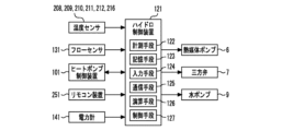
- FIG. 2 is a block diagram showing the configuration of a hydro control device.
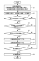
- 4 is a flowchart showing a control operation in the first embodiment.
- 1 is a graph showing the fluctuation of each parameter during hot water supply operation.
- 1 is a diagram showing an example of a configuration for realizing the functions of a heat pump control device and a hydro control device in a first embodiment.
- water and hot water generally mean liquid water, and can include anything from cold water to hot water.
- the configuration shown in the embodiment below shows an example of the technical idea related to this disclosure, and it is possible to combine it with other known technologies, and it is also possible to combine multiple technical ideas described in this disclosure. Furthermore, it is also possible to omit or modify part of the configuration without departing from the gist of this disclosure.
- FIG. 1 is a system circuit diagram of a heat pump system 100 according to the first embodiment of the present disclosure.
- the heat pump system 100 includes a heat pump unit 301 equipped with a refrigerant circuit 51 and a part of a heating circulation circuit 52 of a vapor compression refrigeration cycle (heat pump cycle), a hot water tank unit 302 equipped with a part of the heating circulation circuit 52 and a hot water storage circuit 53, and heating units 305a and 305b configured with a part of the heating circulation circuit 52 and heating the room.
- the heat pump unit 301 and the hot water tank unit 302 are connected via a heat medium pipe 303 and a heat medium pipe 304.
- the hot water tank unit 302 and the heating units 305a and 305b are connected via a heat medium pipe 306 and a heat medium pipe 307.
- the hot water tank unit 302 is also connected to a hot water supply pipe 308 connected to a hot water supply terminal (for example, a faucet in a kitchen or a washroom) and a water supply pipe 309 for supplying water from a water source such as a waterworks.
- the heat pump system 100 corresponds to a hot water supply/air conditioning system having a hot water supply function and an air conditioning function.
- the refrigerant used in the refrigerant circuit 51 of the heat pump unit 301 is not particularly limited, and may be, for example, natural refrigerants such as R410A, R32, HFO-1234yf, hydrocarbons, or carbon dioxide.
- the heat medium used in the heating circulation circuit 52 is not particularly limited, and may be, for example, liquids such as water, ethylene glycol, propylene glycol, Nybrine (Nybrine is a trademark), or mixtures of these. Ethylene glycol, propylene glycol, Nybrine, etc. may be used in any concentration.
- This heat pump system 100 is installed, for example, in an ordinary house or an office building.
- the heat pump system 100 can process a hot water supply command (hot water supply ON/OFF) or a heating command (heating ON/OFF) selected by the hot water storage tank unit 302.
- the heat pump unit 301 is equipped with a refrigerant circuit 51 in which a compressor 1, a condenser 2, an expansion valve 3, and an evaporator 4 are connected in a ring shape by refrigerant piping.
- the compressor 1 sucks in and compresses the refrigerant to a high temperature and high pressure state.
- the compressor 1 is preferably a type whose rotation speed is controlled by, for example, inverter control.
- the condenser 2 heats the heat medium and cools the refrigerant by exchanging heat between the heat medium and the refrigerant.
- the condenser 2 is, for example, a plate type heat exchanger.
- the expansion valve 3 reduces the pressure of the refrigerant to a low temperature and low pressure state.
- the opening degree of the expansion valve 3 is variable.
- the evaporator 4 absorbs heat from the outside air by exchanging heat between the outside air and the refrigerant, and heats the refrigerant.
- the evaporator 4 is, for example, a cross-fin type fin-and-tube air heat exchanger composed of a heat transfer tube and a large number of fins.
- a blower 5 is installed in the evaporator 4.
- the blower 5 draws in outside air, exchanges heat in the evaporator 4, and then discharges the air to the outside.
- the blower 5 includes a fan such as a propeller fan and a motor, such as a DC fan motor, for driving the fan.
- the blower 5 is configured to vary the flow rate of the air it supplies.
- the heat pump unit 301 corresponds to a refrigeration cycle device.
- the heat pump unit 301 further includes a pressure sensor 201 that detects the pressure of the refrigerant discharged from the compressor 1, a temperature sensor 202 that detects the temperature of the refrigerant discharged from the compressor 1, a temperature sensor 203 that detects the temperature of the refrigerant flowing out from the condenser 2, a temperature sensor 204 that detects the temperature of the refrigerant flowing into the evaporator 4, a temperature sensor 205 that detects the temperature of the air flowing into the evaporator 4, i.e., the outside air temperature, a temperature sensor 206 that detects the temperature of the heat medium flowing into the condenser 2, and a temperature sensor 207 that detects the temperature of the heat medium flowing out from the condenser 2.
- a pressure sensor 201 that detects the pressure of the refrigerant discharged from the compressor 1
- a temperature sensor 202 that detects the temperature of the refrigerant discharged from the compressor 1
- a temperature sensor 203 that detects the temperature of the refriger
- the hot water storage tank unit 302 is equipped with a heat medium pump 6, a three-way valve 7, a heating heat exchanger 8, a water pump 9, a hot water storage tank 10, a mixing valve 11, and the like.
- the heat medium pump 6 has a function of circulating the heat medium in the heating circulation circuit 52.
- the heat medium pump 6 may be of a variable speed type (for example, inverter controlled) or a constant speed type.
- the three-way valve 7 functions as a flow path switching means for switching the flow direction of the heat medium. During hot water supply operation in which hot water is supplied to the hot water storage tank 10 and heat is stored in the hot water storage tank 10, the three-way valve 7 is switched so that the heat medium flows to the heating heat exchanger 8.
- the heating heat exchanger 8 heats the water and cools the heat medium by exchanging heat between the heat medium and water.
- the heating heat exchanger 8 is, for example, a plate-type heat exchanger.
- the heat medium and water are configured to flow in the opposite directions in the heating heat exchanger 8.
- the water pump 9 has a function of circulating water in the hot water storage circuit 53.
- the water pump 9 may be of a variable speed type (for example, inverter controlled) or a constant speed type.
- the hot water storage tank 10 (hot water storage tank) has a function of storing heated hot water and water before heating.
- the hot water storage tank 10 is a full water type.
- connection point 14 One end of the hot water storage circuit 53 is connected to a connection point 14 at the bottom of the hot water storage tank 10.
- the other end of the hot water storage circuit 53 is connected to a connection point 17 at the bottom of the hot water storage tank 10, which is higher than the connection point 14.
- the hot water outlet pipe 15 connects the top of the hot water storage tank 10 to the mixing valve 11.
- the water supply pipe 309 is connected to the bottom of the hot water storage tank 10 and the mixing valve 11.
- the hot water supply pipe 308 is further connected to the mixing valve 11.
- hot water flows out from the top of the hot water storage tank 10 to the hot water outlet pipe 15 and is supplied to the mixing valve 11.
- low-temperature water in the same amount as the hot water flowing out to the hot water outlet pipe 15 flows into the bottom of the hot water storage tank 10 from the water supply pipe 309.
- the mixing valve 11 mixes the hot water from the hot water outlet pipe 15 with the low-temperature water from the water supply pipe 309 and sends the water to the hot water supply pipe 308.
- the mixing valve 11 is capable of controlling the mixing ratio of hot water and low-temperature water, and produces hot water at a preset temperature.
- the hot water storage tank unit 302 further includes a temperature sensor 208 that detects the temperature of the heat medium flowing into the heating heat exchanger 8, a temperature sensor 209 that detects the temperature of the heat medium flowing out from the heating heat exchanger 8, a temperature sensor 210 that detects the temperature of the water flowing into the heating heat exchanger 8, a temperature sensor 211 that detects the temperature of the water flowing out from the heating heat exchanger 8, a temperature sensor 212 that detects the water temperature in the hot water storage tank 10, and a temperature sensor 216 that detects the water temperature in the hot water supply pipe 308.
- a temperature sensor 208 that detects the temperature of the heat medium flowing into the heating heat exchanger 8
- a temperature sensor 209 that detects the temperature of the heat medium flowing out from the heating heat exchanger 8
- a temperature sensor 210 that detects the temperature of the water flowing into the heating heat exchanger 8
- a temperature sensor 211 that detects the temperature of the water flowing out from the heating heat exchanger 8
- a temperature sensor 212 that detects the
- the heating units 305a and 305b include radiators 12a and 12b (panel heaters) as heating heat exchangers. A heat medium is caused to flow through the radiators 12a and 12b, whereby the air in the room is heated by radiation.
- the heat pump control device 101 has a measuring means 102 for acquiring pressure or temperature information based on the output of the pressure sensor 201 or the temperature sensors 202, 203, 204, 205, 206, 207, etc., a communication means 103 for transmitting the operating state (temperature, pressure, etc.) or abnormal signals of the heat pump unit 301 to the hydro control device 121, and conversely for receiving the operating state (temperature, equipment operation, etc.) or abnormal signals of the hot water storage tank unit 302 from the hydro control device 121, a calculation means 104 for calculating the condensation temperature or the degree of supercooling based on the measurement information acquired by the measuring means 102, and a control means 105 for controlling the operating state of the heat pump unit 301 (the operating method of the compressor 1 or the opening degree of the expansion valve 3, etc.) based on the measurement information or the calculation results of the calculation means 104.
- the communication means 103 is configured to communicate with a communication means 125 described later, for example, via a telephone line,
- the hydro control device 121 includes a measuring means 122 that acquires temperature information based on the output of the temperature sensors 208, 209, 210, 211, 212, and 216, a storage means 123 that stores the type of heat medium flowing through the heating circulation circuit 52, and an input means 124 that recognizes input such as an ON/OFF command for the operation mode from the user or input information from the installation company, and a heat pump control device 101 that transmits the operation state (temperature or equipment operation, etc.) or an abnormal signal of the hot water storage tank unit 302 to the heat pump control device 101, and conversely, transmits the operation state of the hot water storage tank unit 302 to the heat pump control device 101.
- a measuring means 122 that acquires temperature information based on the output of the temperature sensors 208, 209, 210, 211, 212, and 216
- a storage means 123 that stores the type of heat medium flowing through the heating circulation circuit 52
- an input means 124 that recognizes input such as an ON/OFF command for the operation
- the remote control device 251 is an example of a user interface.
- a human being such as a user can remotely control the heat pump system 100 and perform various settings by operating the remote control device 251.
- the communication between the hydro control device 121 and the remote control device 251 may be wired or wireless.
- the remote control device 251 may be installed in the bathroom.
- the remote control device 251 may be installed in the kitchen.
- the heat pump system 100 may be equipped with multiple remote control devices 251 installed in different locations.
- the remote control device 251 has a display unit, an operation unit, and an audio output unit.
- the display unit may be, for example, a liquid crystal display or an organic EL display.
- the display unit can display, for example, information regarding the state of the heat pump system 100, information regarding the settings of the heat pump system 100, etc.
- the display unit functions as a notification means for notifying a human being such as a user of information.
- the operation unit may include buttons, dials, keys, etc. for the user to operate.
- the display unit may be a touch screen that also has the function of the operation unit.
- the audio output unit functions as a notification means for notifying a person such as a user of information by voice.
- a smartphone or other portable device may be configured to be used as a user interface.
- the heat pump control device 101 is installed in the heat pump unit 301, and the hydro control device 121 is installed in the hot water tank unit 302.
- the heat pump control device 101 may be installed in the hot water tank unit 302, or the hydro control device 121 may be installed in the heat pump unit 301.
- the heat pump control device 101 and the hydro control device 121 may be integrated.
- a control device (not shown) may be provided in a location other than the heat pump unit 301 and the hot water tank unit 302, and the control device may take over some or all of the functions of the heat pump control device 101 and the hydro control device 121.
- the heat pump system 100 controls each device mounted on the heat pump unit 301, the hot water tank unit 302, and the heating units 305a, 305b in accordance with the heating load required for the heating units 305a, 305b and the hot water supply request required for the hot water tank unit 302, and executes a heating operation mode or a hot water supply operation mode.
- Information on ON/OFF of the heating operation mode or the hot water supply operation mode is input to the input means 124 of the hydro control device 121 by the user or automatically based on the time or the like.
- the input information is transmitted to the heat pump control device 101 by the communication means 125. The operation in each operation mode will be described below.
- the heating operation mode will be described.
- the three-way valve 7 is switched so as to connect the outlet of the condenser 2 to the heating units 305a and 305b.
- the heat pump unit 301 and the hot water storage tank unit 302 are operated.
- the refrigerant circuit 51 the high-temperature, high-pressure gas refrigerant discharged from the compressor 1 flows into the condenser 2, where it is cooled by the heat medium to become a high-pressure liquid refrigerant.
- the refrigerant flows out of the condenser 2 and is decompressed by the expansion valve 3 to become a low-pressure two-phase refrigerant.
- the refrigerant flows into the evaporator 4, where it absorbs heat from the outside air to become a low-pressure gas refrigerant. Then, the refrigerant is sucked back into the compressor 1.
- the operating states of the compressor 1, the expansion valve 3, and the blower 5 are controlled by the control means 105 of the heat pump control device 101 according to the temperature or pressure measured by the measurement means 102.
- the heat medium pumped by the heat medium pump 6 flows out of the hot water tank unit 302 and flows into the heat pump unit 301 via the heat medium pipe 304.
- the heat medium is heated by the refrigerant in the condenser 2 and becomes a high-temperature state.
- This high-temperature heat medium flows out of the heat pump unit 301 and flows into the hot water tank unit 302 again via the heat medium pipe 303.
- the heat medium then flows out of the hot water tank unit 302 via the three-way valve 7 and flows into the heating units 305a, 305b via the heat medium pipe 306.
- the room is heated by heat exchange between the heat medium and the indoor air in the radiators 12a, 12b, and the heat medium becomes low temperature.
- the low-temperature heat medium flows out of the heating units 305a, 305b, flows into the hot water tank unit 302 via the heat medium pipe 307, and flows into the heat medium pump 6 again.
- the operating state of the heat transfer medium pump 6 is controlled by the control means 127 of the hydro control device 121 according to the measured temperature or pressure.
- the water in the hot water storage tank 10 is not heated, so the water pump 9 is stopped and water does not flow in the hot water storage circuit 53.
- the hot water supply operation mode Next, the hot water supply operation mode will be described.
- the arrows in FIG. 1 indicate the flow directions of the refrigerant, heat medium, and water in the hot water supply operation mode.
- the three-way valve 7 is switched so as to connect the outlet of the condenser 2 and the inlet of the heating heat exchanger 8.
- the heat pump unit 301 and the hot water storage tank unit 302 are operated.
- the refrigerant circuit 51 the high-temperature, high-pressure gas refrigerant discharged from the compressor 1 flows into the condenser 2, where it is cooled by the heat medium to become a high-pressure liquid refrigerant.
- the refrigerant then flows out of the condenser 2 and is decompressed by the expansion valve 3 to become a low-pressure two-phase refrigerant.
- the refrigerant then flows into the evaporator 4, where it absorbs heat from the outside air to become a low-pressure gas refrigerant.
- the refrigerant is then sucked back into the compressor 1.
- the operating states of the compressor 1, the expansion valve 3, and the blower 5 are controlled by the control means 105 of the heat pump control device 101 according to the temperature or pressure measured by the measurement means 102.
- the heat medium pumped by the heat medium pump 6 flows out of the hot water tank unit 302 and flows into the heat pump unit 301 via the heat medium piping 304.
- the heat medium is heated by the refrigerant in the condenser 2 and becomes a high-temperature state.
- This high-temperature heat medium flows out of the heat pump unit 301 and flows back into the hot water tank unit 302 via the heat medium piping 303.
- the heat medium then flows into the heating heat exchanger 8 via the three-way valve 7, where it exchanges heat with water to heat the water, and the heat medium becomes low in temperature. This heat medium with a reduced temperature then flows back into the heat medium pump 6.
- connection point 14 of the hot water storage tank 10 water flowing out from connection point 14 of the hot water storage tank 10 is sent to the heating heat exchanger 8 by the water pump 9. This water is heated by the heat medium in the heating heat exchanger 8 to become hot water.
- the hot water flowing out from the heating heat exchanger 8 flows into the hot water storage tank 10 from connection point 17 and is stored.
- connection point 14 of the hot water storage tank 10 As water continuously flows out from connection point 14 of the hot water storage tank 10 and hot water continuously flows into connection point 17, the water temperature in the hot water storage tank 10 increases. Note that in the hot water supply operation mode, the room is not heated and no heat medium flows through the heating units 305a and 305b.
- the water heated by the heating heat exchanger 8 flows into the hot water storage tank 10 through the connection point 17 at the bottom of the hot water storage tank 10. Low-temperature water is present at the bottom of the hot water storage tank 10.
- the hot water supply operation in this embodiment is an operation that gradually raises the temperature of the entire hot water storage tank 10, and hot water is stored in the hot water storage tank 10 by multiple heat exchanges in the heating heat exchanger 8.
- This heating method is called circulating heating. In circulating heating, the water is heated by the heating heat exchanger 8, for example, by 5°C, to raise the water temperature of the hot water storage tank 10.
- the temperature of the water flowing into the heating heat exchanger 8 rises, for example, to 25°C, 30°C, ..., and the temperature of the water flowing out of the heating heat exchanger 8 also rises accordingly, to 30°C, 35°C, ....
- the water temperature in the hot water storage tank 10 is low, and the temperature of the heat medium flowing into the heating heat exchanger 8 and the temperature of the water flowing out of the heating heat exchanger 8 are also low, so the temperature of the heat medium flowing out of the condenser 2 and the temperature of the heat medium flowing into the condenser 2 are low.
- the operating efficiency of the heat pump unit 301 is high.
- the water pump 9 is controlled as follows. In order to keep the temperature of the heat medium flowing into the heating heat exchanger 8 low, the water flow rate is increased to lower the temperature of the water flowing out of the heating heat exchanger 8. In other words, the water pump 9 is operated at a constant flow rate, for example, such that the temperature difference between the water inlet and outlet of the heating heat exchanger 8 is about 5°C. For example, when the heating capacity of the heating heat exchanger 8 is 9 kW, the specific heat of water is 4.18 kJ/kgK, and the density of water is 1000 kg/ m3 , the required water flow rate is 25.84 liters/minute. Therefore, a pump that can ensure a flow rate of 25.84 liters/minute is selected as the water pump 9.
- the heat medium pump 6 must also ensure that the flow rate of the heat medium is equal to or greater than the flow rate of the water in order to make the temperature difference between the inlet and outlet of the heat medium in the heating heat exchanger 8 equal to or less than the temperature difference between the inlet and outlet of the water. In other words, if the flow rate of water delivered by the water pump 9 is 25.84 liters/minute, then the heat medium pump 6 must be one that can ensure a flow rate of 25.84 liters/minute or more.
- the high-pressure liquid refrigerant temperature is the temperature of the refrigerant flowing through the refrigerant circuit 51 at the outlet of the condenser 2.
- the target value of the high-pressure liquid refrigerant temperature is set according to either the temperature of the heat medium flowing into the condenser 2 or the temperature of the heat medium flowing out of the condenser 2, and the expansion valve 3 is controlled so that the high-pressure liquid refrigerant temperature becomes the target value.
- the target value of the high-pressure liquid refrigerant temperature can be, for example, a value 3°C higher than the temperature of the heat medium flowing into the condenser 2.
- the expansion valve 3 may be controlled so that the degree of subcooling of the condenser 2 becomes the target value (for example, 2°C).
- the degree of subcooling of the condenser 2 is the value obtained by subtracting the temperature detected by the temperature sensor 203 from the saturation temperature of the pressure detected by the pressure sensor 201.
- the heat pump system 100 is capable of performing heating operation and hot water supply operation, and can perform hot water supply operation with high efficiency. Specifically, by using the heating heat exchanger 8 installed outside the hot water storage tank 10, heat transfer performance is improved. Since the temperature of the heat medium flowing into the heat pump unit 301 can be lowered, the heat pump unit 301 can be operated with high operating efficiency. In addition, since the heating heat exchanger 8 is installed outside the hot water storage tank 10, it can be easily replaced if a malfunction occurs in the heating heat exchanger 8, improving maintainability.
- the heating capacity of the heat pump unit 301 corresponds to the capacity of the refrigeration cycle device.
- the hydro control device 121 can calculate the heating capacity [kW] of the heat pump unit 301 by the following formula based on the outlet water temperature detected by the temperature sensor 208, the inlet water temperature detected by the temperature sensor 209, and the flow rate of the heat medium detected by the flow sensor 131.
- the specific heat of the heat medium and the density of the heat medium are stored in the storage means 123.
- Heating capacity Heat transfer medium flow rate x Heat transfer medium specific heat x Heat transfer medium density x (Outlet water temperature - Inlet water temperature)
- the temperature sensors 208, 209 and the flow sensor 131 correspond to a capacity detector that detects the capacity of the refrigeration cycle device.
- the heat pump control device 101 and the hydro control device 121 are configured to perform COP protection control during hot water supply operation.
- the COP protection control is a control that reduces the operating capacity of the refrigeration cycle device so that the actual COP does not become equal to or lower than the COP protection value.
- the COP protection value is stored in the storage means 123.
- the operating capacity of the refrigeration cycle device is reduced by lowering the frequency of compressor 1.
- This configuration is not limited to this, and in a system having multiple compressors, the operating capacity of the refrigeration cycle device may be reduced by reducing the number of operating compressors.
- the temperature of the heat medium flowing into the condenser 2 gradually rises.
- the COP also gradually decreases.
- the COP protection value may be 3.0, for example.
- the heating capacity is maintained at a high level from the beginning to the middle of hot water supply operation when the temperature of the heat medium flowing into the condenser 2 is not high, and when the temperature of the heat medium flowing into the condenser 2 becomes high, the COP is maintained at a high level, making it possible to achieve energy savings while maintaining the hot water supply operation time long enough to avoid running out of hot water.
- the heating capacity protection value in this embodiment is an example of a refrigeration cycle capacity protection value.
- the heating capacity protection value is stored in the storage means 123.
- the heat pump control device 101 may be configured not to further reduce the frequency of the compressor 1 when the heating capacity falls below the heating capacity protection value during COP protection control. This makes it possible to prevent an extreme reduction in heating capacity due to an excessive reduction in the frequency of the compressor 1, and more reliably avoid running out of hot water.
- the heating capacity protection value may be a value equivalent to 50% of the rated capacity.
- the heat pump control device 101 may be configured to increase the heating capacity protection value when the outdoor temperature is low compared to when the outdoor temperature is high. This makes it possible to more reliably avoid running out of hot water by increasing the heating capacity protection value when the outdoor temperature is low, limiting the amount of reduction in the compressor frequency and preventing a significant loss of heating capacity.
- the user may be able to select ON/OFF of the energy saving priority mode by operating the remote control device 251.
- the energy saving priority mode is a mode in which operation prioritizes energy saving compared to the normal mode.
- the heat pump control device 101 and the hydro control device 121 may be configured to implement COP protection control when the energy saving priority mode is ON, and not to implement COP protection control when the energy saving priority mode is OFF. In other words, when the energy saving priority mode is OFF, the heat pump control device 101 does not reduce the frequency of the compressor 1 even if the actual COP falls below the COP protection value. As a result, if the user knows in advance that hot water consumption is high, the user can shorten the hot water supply operation time by turning off the energy saving priority operation mode, thereby reliably avoiding running out of hot water.
- the heat pump control device 101 may be configured to reduce the rotation speed of the blower 5 when the frequency of the compressor 1 is reduced during COP protection control. This allows the blowing flow rate output by the blower 5 to be adjusted to match the refrigerant flow rate output by the compressor 1, reducing unnecessary fan blowing power and saving energy.
- the heat pump control device 101 may be configured to reduce the frequency of the compressor 1 when COP protection control is being implemented to 65% to 70% of the compressor frequency when COP protection control is not being implemented when the outdoor temperature is 7°C or higher. In other words, the heat pump control device 101 may be configured not to reduce the frequency of the compressor 1 when COP protection control is being implemented to less than 65% of the maximum frequency when the outdoor temperature is 7°C or higher. It is known that the heating load is about 65% of the catalog capacity at an outdoor temperature of 7°C as a standard load in warm regions of Europe. For this reason, it can be said that heating comfort is not impaired even if the frequency of the compressor 1 is reduced to 65%, so it can be said that it is better to limit the reduction in the compressor frequency to 65% to 70%.
- FIG. 4 is a flowchart showing the control operation in the first embodiment. The following will be described with reference to the flowchart in FIG. 4.
- step S1 the heat pump control device 101 and the hydro control device 121 start hot water supply operation.
- the compressor frequency is fixed to the hot water supply frequency
- the blower rotation speed is fixed to the hot water supply rotation speed.
- the hot water supply frequency may be the maximum frequency.
- the hot water supply rotation speed may be the maximum rotation speed.
- step S2 the hydro control device 121 measures the power consumption using the power meter 141, calculates the heating capacity, and calculates the actual COP.
- step S3 it is determined whether the energy saving priority mode is ON. If the energy saving priority mode is not ON, the process proceeds to step S8.
- step S8 the hydro control device 121 determines whether the hot water supply operation has been completed. If the hot water supply operation has not been completed, the process returns to step S2. If the hot water supply operation has been completed, the process proceeds to step S9, and the hot water supply operation is ended.
- step S4 the hydro control device 121 determines whether the heating capacity is equal to or greater than the heating capacity protection value. If the heating capacity is not equal to or greater than the heating capacity protection value, the process proceeds to step S8. On the other hand, if the heating capacity is equal to or greater than the heating capacity protection value, the process proceeds to step S5, where the hydro control device 121 determines whether the actual COP is equal to or less than the COP protection value. If the actual COP is equal to or less than the COP protection value, the process proceeds to step S6, where the heat pump control device 101 performs a process to reduce the frequency of the compressor 1.
- step S7 the heat pump control device 101 performs a process to reduce the rotation speed of the blower 5. Thereafter, the process proceeds to step S8. Also, if the actual COP is not equal to or less than the COP protection value in step S5, the process proceeds to step S8.
- the number of times the rotation speed of the blower 5 is reduced may be less than the number of times the frequency of the compressor 1 is reduced.
- the rotation speed of the blower 5 may be reduced once for every three times the frequency of the compressor 1 is reduced.
- FIG. 5 is a graph showing the fluctuations of each parameter during hot water supply operation.
- Hot water supply operation begins at time t1 in Figure 5.
- the temperature of the heat medium flowing into the condenser 2 gradually increases, and the heating capacity and COP gradually decrease accordingly.
- COP protection control is initiated, and the heat pump control device 101 reduces the compressor frequency to prevent the COP from decreasing any further.
- the heat pump control device 101 gradually reduces the compressor frequency, and when the heating capacity falls to the heating capacity protection value at time t3, the heat pump control device 101 prevents a decrease in heating capacity by not further reducing the compressor frequency.
- FIG. 6 is a diagram showing an example of a configuration for realizing the functions of the heat pump control device 101 and the hydro control device 121 in the first embodiment.
- the processing circuit may be dedicated hardware 600.
- the processing circuit may include a processor 601 and a memory 602. A part of the processing circuit may be formed as the dedicated hardware 600, and the processing circuit may further include a processor 601 and a memory 602. In the example shown in FIG. 6, a part of the processing circuit is formed as the dedicated hardware 600.
- the processing circuit further includes a processor 601 and a memory 602 in addition to the dedicated hardware 600.
- a processing circuit part of which is at least one dedicated hardware 600, may be, for example, a single circuit, a composite circuit, a programmed processor, a parallel programmed processor, an ASIC, an FPGA, or a combination of these.
- the processing circuit has at least one processor 601 and at least one memory 602, the functions of each part of the heat pump control device 101 and the hydro control device 121 are realized by software, firmware, or a combination of software and firmware.
- the software and firmware are written as programs and stored in memory 602.
- the programs may be recorded on a computer-readable recording medium.
- Processor 601 realizes the functions of each part by reading and executing the programs stored in memory 602.
- Processor 601 is also called a CPU (Central Processing Unit), central processing unit, processing unit, arithmetic unit, microprocessor, microcomputer, or DSP.
- Memory 602 includes, for example, non-volatile or volatile semiconductor memory such as RAM, ROM, flash memory, EPROM, and EEPROM, or magnetic disks, flexible disks, optical disks, compact disks, mini disks, and DVDs.
- the processing circuit can realize the functions of the heat pump control device 101 and the hydro control device 121 by hardware, software, firmware, or a combination of these.
- each function of the heat pump control device 101 and the hydro control device 121 may be realized by multiple devices working together, or may be realized by a single device.
- at least a portion of each function of the heat pump control device 101 and the hydro control device 121 may be implemented on a server or the like on an external network.
Landscapes
- Engineering & Computer Science (AREA)
- Physics & Mathematics (AREA)
- Thermal Sciences (AREA)
- Mechanical Engineering (AREA)
- General Engineering & Computer Science (AREA)
- Chemical & Material Sciences (AREA)
- Combustion & Propulsion (AREA)
- Heat-Pump Type And Storage Water Heaters (AREA)
Abstract
Un système de pompe à chaleur selon la présente divulgation comprend : un dispositif à cycle de réfrigération; un compteur électrique qui mesure la consommation d'énergie du dispositif à cycle de réfrigération; un détecteur de performances qui détecte les performances du dispositif à cycle de réfrigération; et un circuit de commande configuré pour effectuer une commande de garde de coefficient de performances, COP, pour abaisser la capacité opérationnelle du dispositif à cycle de réfrigération de telle sorte qu'un COP réel calculé à partir de la consommation d'énergie et des performances du dispositif à cycle de réfrigération ne chute pas jusqu'à une valeur de garde de COP ou ou au-dessous de celle-ci. Le système de pompe à chaleur effectue la commande de garde de COP pendant une opération de chauffage d'eau, qui est une opération pour chauffer de l'eau au moyen du dispositif à cycle de réfrigération.
Priority Applications (1)
| Application Number | Priority Date | Filing Date | Title |
|---|---|---|---|
| PCT/JP2023/032390 WO2025052548A1 (fr) | 2023-09-05 | 2023-09-05 | Système de pompe à chaleur |
Applications Claiming Priority (1)
| Application Number | Priority Date | Filing Date | Title |
|---|---|---|---|
| PCT/JP2023/032390 WO2025052548A1 (fr) | 2023-09-05 | 2023-09-05 | Système de pompe à chaleur |
Publications (1)
| Publication Number | Publication Date |
|---|---|
| WO2025052548A1 true WO2025052548A1 (fr) | 2025-03-13 |
Family
ID=94923002
Family Applications (1)
| Application Number | Title | Priority Date | Filing Date |
|---|---|---|---|
| PCT/JP2023/032390 Pending WO2025052548A1 (fr) | 2023-09-05 | 2023-09-05 | Système de pompe à chaleur |
Country Status (1)
| Country | Link |
|---|---|
| WO (1) | WO2025052548A1 (fr) |
Citations (7)
| Publication number | Priority date | Publication date | Assignee | Title |
|---|---|---|---|---|
| JP2002333230A (ja) * | 2001-05-07 | 2002-11-22 | Matsushita Electric Ind Co Ltd | 熱電子ヒートポンプ装置 |
| JP2005241088A (ja) * | 2004-02-25 | 2005-09-08 | Corona Corp | 貯湯式給湯装置 |
| WO2011129248A1 (fr) * | 2010-04-15 | 2011-10-20 | 三菱電機株式会社 | Dispositif de commande pour système de chauffe-eau, programme pour commander un système de chauffe-eau, et procédé pour faire fonctionner un système de chauffe-eau |
| JP2016102607A (ja) * | 2014-11-28 | 2016-06-02 | 株式会社富士通ゼネラル | ヒートポンプ式暖房給湯装置 |
| JP2017161197A (ja) * | 2016-03-11 | 2017-09-14 | 株式会社富士通ゼネラル | 空気調和システム |
| JP2019163869A (ja) * | 2018-03-19 | 2019-09-26 | 三菱電機冷熱プラント株式会社 | 冷却装置とその制御方法および制御プログラム |
| WO2021191949A1 (fr) * | 2020-03-23 | 2021-09-30 | 東芝キヤリア株式会社 | Dispositif de source de chaleur pour pompe à chaleur et chauffe-eau à pompe à chaleur |
-
2023
- 2023-09-05 WO PCT/JP2023/032390 patent/WO2025052548A1/fr active Pending
Patent Citations (7)
| Publication number | Priority date | Publication date | Assignee | Title |
|---|---|---|---|---|
| JP2002333230A (ja) * | 2001-05-07 | 2002-11-22 | Matsushita Electric Ind Co Ltd | 熱電子ヒートポンプ装置 |
| JP2005241088A (ja) * | 2004-02-25 | 2005-09-08 | Corona Corp | 貯湯式給湯装置 |
| WO2011129248A1 (fr) * | 2010-04-15 | 2011-10-20 | 三菱電機株式会社 | Dispositif de commande pour système de chauffe-eau, programme pour commander un système de chauffe-eau, et procédé pour faire fonctionner un système de chauffe-eau |
| JP2016102607A (ja) * | 2014-11-28 | 2016-06-02 | 株式会社富士通ゼネラル | ヒートポンプ式暖房給湯装置 |
| JP2017161197A (ja) * | 2016-03-11 | 2017-09-14 | 株式会社富士通ゼネラル | 空気調和システム |
| JP2019163869A (ja) * | 2018-03-19 | 2019-09-26 | 三菱電機冷熱プラント株式会社 | 冷却装置とその制御方法および制御プログラム |
| WO2021191949A1 (fr) * | 2020-03-23 | 2021-09-30 | 東芝キヤリア株式会社 | Dispositif de source de chaleur pour pompe à chaleur et chauffe-eau à pompe à chaleur |
Similar Documents
| Publication | Publication Date | Title |
|---|---|---|
| CN103975204B (zh) | 热泵式制热和热水供给系统 | |
| JP5642203B2 (ja) | ヒートポンプ装置及びヒートポンプ装置の制御方法 | |
| JP6545375B2 (ja) | ヒートポンプ式空調給湯装置 | |
| JP6636048B2 (ja) | 空気調和装置 | |
| JP2015145759A (ja) | 空気調和システム | |
| WO2018092357A1 (fr) | Appareil de commande de climatisation et procédé de commande de climatisation | |
| KR101825636B1 (ko) | 냉방, 난방 및 급탕기능을 구비한 히트펌프 | |
| JP2015206570A (ja) | 換気装置及び換気空調システム | |
| CN105890225A (zh) | 一种部分热回收型空调冷热水及生活热水联合供应系统 | |
| JP2012013357A (ja) | ヒートポンプ式温水暖房装置 | |
| WO2022064060A1 (fr) | Système de pompe à chaleur | |
| JP2009264717A (ja) | ヒートポンプ温水システム | |
| KR20030084686A (ko) | 히트 펌프식 온수 난방 장치 | |
| JP2012013356A (ja) | ヒートポンプ式温水暖房装置 | |
| JP2003222395A (ja) | 多機能給湯装置 | |
| JP2009287898A (ja) | ヒートポンプ式温水熱利用システム | |
| WO2025052548A1 (fr) | Système de pompe à chaleur | |
| KR20100029374A (ko) | 히트펌프 연동 온수 순환 시스템 및 제어 방법 | |
| WO2017046853A1 (fr) | Dispositif de climatisation et procédé de commande de climatisation | |
| WO2025154239A1 (fr) | Système de pompe à chaleur | |
| KR101488903B1 (ko) | 축열장치 및 그 운전방법 | |
| JP2019219064A (ja) | 給湯暖房装置 | |
| WO2025220070A1 (fr) | Système de climatisation/d'alimentation en eau chaude | |
| JP7149763B2 (ja) | 給湯装置 | |
| JP2002147883A (ja) | 温水冷媒加熱エアコン及びその制御方法 |
Legal Events
| Date | Code | Title | Description |
|---|---|---|---|
| 121 | Ep: the epo has been informed by wipo that ep was designated in this application |
Ref document number: 23951452 Country of ref document: EP Kind code of ref document: A1 |