WO2025052844A1 - Terminal, management server, communication system, method, and program - Google Patents
Terminal, management server, communication system, method, and program Download PDFInfo
- Publication number
- WO2025052844A1 WO2025052844A1 PCT/JP2024/028166 JP2024028166W WO2025052844A1 WO 2025052844 A1 WO2025052844 A1 WO 2025052844A1 JP 2024028166 W JP2024028166 W JP 2024028166W WO 2025052844 A1 WO2025052844 A1 WO 2025052844A1
- Authority
- WO
- WIPO (PCT)
- Prior art keywords
- terminal
- data
- haptic data
- communication
- network
- Prior art date
- Legal status (The legal status is an assumption and is not a legal conclusion. Google has not performed a legal analysis and makes no representation as to the accuracy of the status listed.)
- Ceased
Links
Images




Classifications
-
- G—PHYSICS
- G06—COMPUTING OR CALCULATING; COUNTING
- G06F—ELECTRIC DIGITAL DATA PROCESSING
- G06F3/00—Input arrangements for transferring data to be processed into a form capable of being handled by the computer; Output arrangements for transferring data from processing unit to output unit, e.g. interface arrangements
- G06F3/01—Input arrangements or combined input and output arrangements for interaction between user and computer
-
- H—ELECTRICITY
- H04—ELECTRIC COMMUNICATION TECHNIQUE
- H04L—TRANSMISSION OF DIGITAL INFORMATION, e.g. TELEGRAPHIC COMMUNICATION
- H04L65/00—Network arrangements, protocols or services for supporting real-time applications in data packet communication
- H04L65/80—Responding to QoS
-
- H—ELECTRICITY
- H04—ELECTRIC COMMUNICATION TECHNIQUE
- H04N—PICTORIAL COMMUNICATION, e.g. TELEVISION
- H04N21/00—Selective content distribution, e.g. interactive television or video on demand [VOD]
- H04N21/40—Client devices specifically adapted for the reception of or interaction with content, e.g. set-top-box [STB]; Operations thereof
- H04N21/43—Processing of content or additional data, e.g. demultiplexing additional data from a digital video stream; Elementary client operations, e.g. monitoring of home network or synchronising decoder's clock; Client middleware
- H04N21/437—Interfacing the upstream path of the transmission network, e.g. for transmitting client requests to a VOD server
Definitions
- This disclosure relates to a terminal, a management server, a communication system, a method, and a program.
- Patent Document 1 discloses a connection management system that includes a concierge assistant service for handling a wide range of topics and user intents via a common interface.
- the connection management system interprets the intent of natural language communication received from a user device and automatically determines the social network member endpoint that will receive the natural language communication based on the intent.
- haptic data which is data related to at least one of the tactile and/or kinesthetic senses
- the receiving device that receives the haptic data transmits the data to the user via an interface. This allows the user to experience virtual reality related to touch, etc.
- a user when a user performs remote operation on one device, data related to the remote operation instructions is transmitted from one device to the other device.
- the other device performs an operation based on those instructions.
- the other device transmits haptic data generated by the operation to the one device. Because the user can experience the haptic data via the interface, they can get the feeling that they are actually performing some kind of action on the spot. This allows the user to perform the operation they desire.
- Patent Document 1 does not address this issue, as it is not targeted at haptic technology.
- the present disclosure has as an example an objective to provide a terminal, management server, communication system, method, and program capable of improving the communication performance of haptic data. It should be noted that this objective is merely one of multiple objectives that the multiple embodiments disclosed herein attempt to achieve. Other objectives or problems and novel features will become apparent from the description in this specification or the accompanying drawings.
- a terminal includes a receiving unit that receives haptic data from other terminals connected via a network, a generating unit that generates instruction information for a management server on the network based on an indicator indicating the communication state of the haptic data to execute control regarding the communication of the haptic data with the other terminals, and a transmitting unit that transmits the instruction information to the management server.
- a management server includes a receiving unit that is connected to a first terminal via a network and receives instruction information from a second terminal that receives haptic data from the first terminal, for executing control over communication of the haptic data with the first terminal, and a control executing unit that executes control over communication of the haptic data based on the instruction information.
- a communication system includes a terminal and a management server.
- the terminal includes a receiving unit that receives haptic data from other terminals connected via a network, a generating unit that generates instruction information for the management server on the network based on an indicator indicating a communication state of the haptic data to execute control regarding the communication of the haptic data with the other terminals, and a transmitting unit that transmits the instruction information to the management server.
- the management server includes a receiving unit that receives the instruction information from the terminal, and a control executing unit that executes control regarding the communication of the haptic data based on the instruction information.
- a method is performed by a computer to receive haptic data from another terminal connected via a network, generate instruction information for a management server on the network based on an indicator of a communication state of the haptic data, for controlling communication of the haptic data with the other terminal, and transmit the instruction information to the management server.
- a method is implemented by a computer that receives, from a second terminal that is connected to a first terminal via a network and receives haptic data from the first terminal, instruction information for executing control related to communication of the haptic data with the first terminal, and executes control related to the communication of the haptic data based on the instruction information.
- a program causes a computer to receive haptic data from another terminal connected via a network, generate instruction information for a management server on the network based on an indicator indicating a communication state of the haptic data, for controlling communication of the haptic data with the other terminal, and transmit the instruction information to the management server.
- a program causes a computer to receive, from a second terminal that is connected to a first terminal via a network and receives haptic data from the first terminal, instruction information for executing control over communication of the haptic data with the first terminal, and execute control over the communication of the haptic data based on the instruction information.
- a terminal a management server, a communication system, a method, and a program that can improve the communication performance of haptic data.
- FIG. 2 is a block diagram illustrating an example of a terminal according to the present disclosure.
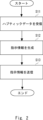
- 10 is a flowchart illustrating an example of a representative process of a terminal according to the present disclosure.
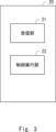
- FIG. 2 is a block diagram illustrating an example of a management server according to the present disclosure.
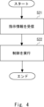
- 13 is a flowchart illustrating an example of a representative process of a management server according to the present disclosure.
- FIG. 1 is a block diagram illustrating an example of a remote control system according to the present disclosure.
- FIG. 1 illustrates an example of a haptic encoder selection scheme according to the present disclosure.
- 1A-1C illustrate different examples of haptic encoder selection schemes according to the present disclosure.
- FIG. 13 is a diagram showing a specific example of the SEEHC header.
- FIG. 1 is a table illustrating SEEHC header coding.
- FIG. 13 is a diagram showing an example of a payload configuration of a feedback bitstream corresponding to a forward bitstream.
- FIG. 11 is a diagram showing another specific example of the SEEHC header.
- FIG. 13 is a diagram showing another example of the payload structure of a feedback bitstream corresponding to a forward bitstream.
- 1 is a table showing actions associated with the SEEHC scheme when there is no delay.
- 1 is a table showing actions associated with the SEEHC scheme when there is a delay.
- FIG. 11 is a sequence diagram showing a procedure for detecting an SE server that is initiated and executed by a leader terminal.
- FIG. 11 is a sequence diagram showing a procedure for detecting an SE server that is initiated and executed by a follower terminal.
- FIG. 13 is an image showing training of SE server 140 with expert profiles.
- FIG. 1 is a block diagram showing an effect of the present disclosure.
- FIG. 2 is a block diagram illustrating an example of a hardware configuration of an information processing device.
- FIG. 1 is a block diagram showing an example of a terminal.
- the terminal 10 is any type of computer that includes a receiving unit 11, a generating unit 12, and a transmitting unit 13. Each unit (means) of the terminal 10 is controlled by a control unit (controller) not shown. Each unit will be described below.
- the receiving unit 11 receives haptic data from other terminals connected via the network.
- haptic data is data related to at least either the sense of touch or the sense of movement.
- the haptic data transmitted by the other terminals is generated, for example, due to an action by a human or a machine (e.g., a robot) being executed on the other terminal side.
- the haptic data acquired by the other terminals is transmitted to the terminal 10.
- the network connecting the terminal 10 and other terminals may be any type of network.
- a management server that manages communication related to haptic data between the terminal 10 and other terminals is provided on the network.
- the generating unit 12 generates instruction information for a management server on the network to execute control regarding the communication of haptic data with other terminals, based on an indicator indicating the communication status of the haptic data received by the receiving unit 11.
- the index indicating the communication state of the haptic data is any qualitative or quantitative index relating to the communication state.
- the index include QoE (Quality of Experience), QoS (Quality of Service), packet loss, transmission delay, etc., but the indexes that can be used are not limited to these.
- This index may be obtained by the terminal 10 analyzing the haptic data received by the receiving unit 11. Alternatively, when a user of the terminal 10 experiences haptic data, the user may input the QoE relating to that data into the terminal 10, and the terminal 10 may obtain the QoE. A specific example of this will be described later in embodiment 2.
- examples of the instruction information generated by the generation unit 12 include the following.
- the parameters related to the network predicted by the management server in (A) may be, but are not limited to, at least one of packet loss, packet error, CRC (Cyclic Redundancy Check) error, error rate, bit rate, jitter, transmission delay, transmission speed, connection loss, bandwidth, capacity, load balancing, HAV data configuration, data stream, data flow, active session, retransmission, and codec selection.
- the management server may predict what kind of haptic data will be generated as a result of a human or machine action performed on the other terminal side. The management server can insert data generated as a result of the prediction into the haptic data acquired from the other terminal and transmitted to the terminal 10, and transmit the data to the terminal 10.
- the objects predicted in (B) are not limited to this.
- the transmission unit 13 transmits the instruction information to the management server.
- the transmission unit 13 is configured as an interface used for wireless or wired communication with other terminals.
- the receiving unit 11 receives haptic data from another terminal connected via the network (step S11).
- the generating unit 12 generates instruction information for changing the control regarding the communication of haptic data with another terminal based on an indicator indicating the communication state of the haptic data (step S12).
- the transmitting unit 13 transmits the instruction information to the management server (step S13).
- the terminal 10 can generate instruction information based on an index indicating a communication state of the haptic data and transmit the instruction information to the management server. Therefore, the terminal 10 can improve the communication performance of the haptic data through the control of the management server.
- the terminal 10 can cause the management server to predict network parameters and control communications based on the predicted parameters. Therefore, through the control of the management server, the terminal 10 can improve the communication performance of haptic data so that the network parameters are favorable.
- terminal 10 can have the management server predict haptic data to be generated on the other terminal side, and based on the predicted haptic data, change the content of the haptic data to be transmitted to the terminal and transmit it to the terminal.
- terminal 10 through the control of the management server, can make the haptic data it receives closer to the content generated on the other terminal side and that should originally be transmitted to terminal 10. Therefore, terminal 10 can improve the communication performance of haptic data so that terminal 10 can receive haptic data that is close to the original data.
- FIG. 3 is a block diagram showing an example of the management server.
- the management server 20 is any type of computer equipped with a receiving unit 21 and a control execution unit 22. Each unit (each means) of the management server 20 is controlled by a control unit (controller) not shown. Each unit will be described below.
- the receiving unit 21 is connected to a first terminal via a network, and receives instruction information from a second terminal that receives haptic data from the first terminal, for changing control over communication of haptic data with the first terminal.
- haptic data, instruction information, and network are the same as those in (1A), and therefore will not be repeated.
- the control execution unit 22 executes control regarding the communication of haptic data based on the instruction information received by the receiving unit 21.
- the control execution unit 22 predicts parameters related to the network between the first terminal and the second terminal, and controls the communication between the first terminal and the second terminal based on the predicted parameters.
- the control execution unit 22 predicts haptic data to be generated on the first terminal side, and based on the predicted haptic data, controls the content of the haptic data to be transmitted to the second terminal to be changed and transmitted to the terminal.
- the control executed by the control execution unit 22 is not limited to this.
- the management server 20 may transmit information indicating the content of the executed control to at least one of the first terminal or the second terminal.
- [Explanation of processing flow] 4 is a flowchart showing an example of a representative process of the management server 20, and an overview of the process of the management server 20 will be described with reference to this flowchart. Note that the details of each process are as described above, and therefore will not be described here.
- the receiver 21 receives instruction information from the second terminal for executing control related to the communication of haptic data with the first terminal (step S21).
- the control execution unit 22 executes control related to the communication of haptic data based on the instruction information (step S22).
- the management server 20 executes control regarding the communication of haptic data based on instruction information received from the terminal. Therefore, the management server 20 can improve the communication performance of the haptic data in response to an instruction from the terminal.
- Embodiment 2 In the following second embodiment, a specific example of the terminal and management server described in the first embodiment will be disclosed. However, the specific examples of the terminal and management server shown in the first embodiment are not limited to those shown below. Furthermore, the configurations and processes described below are examples and are not limited to these. It goes without saying that all or any part of the configurations described in the second embodiment can be appropriately applied to the first embodiment, and the drawings shown in the second embodiment can be appropriately applied to the first embodiment.
- FIG. 5 is a block diagram showing an example of a remote control system.
- the remote control system 100 is a wide area communication network system including a leader terminal 110, a follower terminal 120, a network 130, and an SE (Support Engine) server 140.
- the leader terminal 110 and the follower terminal 120 correspond to the terminal 10 of the first embodiment
- the SE server 140 corresponds to the management server 20 of the first embodiment.
- the remote operation system 100 is a system that supports medical procedures such as surgery in a remote location.
- the follower terminal 120 is a terminal that is placed at a location where surgery is actually performed on a patient
- the leader terminal 110 is a terminal that is placed at a location where the surgeon (i.e., the user of the leader terminal 110) who performs the surgery performs the operation.
- the leader terminal 110 transmits instructions regarding the operation to the follower terminal 120.
- the follower terminal 120 controls a surgical robot connected to the follower terminal 120 based on the received instructions. In this way, the surgical robot operates according to the surgeon's operation and performs surgery on the patient.
- the surgery targets any part of the body (including, for example, the brain, nerves, etc.).
- the remote operation system 100 can be applied to any medical procedure that invades the patient's body, such as biopsies, injections, and cancer treatments, in addition to surgery.
- the application of the remote operation system 100 is not limited to this.
- the leader terminal 110 may transmit instructions to the follower terminal 120 regarding any action performed by the user, not limited to the user's actions.
- the leader terminal 110 comprises a physical environment 111, a virtual environment 112, a HAV (Haptic Audio Video) data processing unit 113, an encoder/decoder 114, and a QoE acquisition unit 115. Each element of the leader terminal 110 is described below.
- HAV Heaptic Audio Video
- the leader terminal 110 is configured to perform its processing using the physical environment 111 or the virtual environment 112. Note that the leader terminal 110 may be configured to have either the physical environment 111 or the virtual environment 112, rather than both.
- the HAV data processing unit 113 generates HAV data based on data acquired from a sensor connected to the reader terminal 110.
- the generated HAV data includes haptic data, audio data, and video data.
- the sensor is attached to, for example, the surgeon's hand, acquires data on the movement of the surgeon's hand, and transmits it to the HAV data processing unit 113.
- the HAV data processing unit 113 processes the received data to generate HAV data.
- data may be transmitted to the HAV data processing unit 113 from any interface, not limited to sensors.
- the HAV data may include haptic data and audio data or video data, or may be data that does not include audio data or video data and includes haptic data.
- the HAV data processing unit 113 also generates a SEEHC header that includes the selection of a haptic encoder to be used for communicating HAV data and instruction information for the SE server 140, as described below.
- the encoder/decoder 114 is a unit that has both the functions of an encoder and a decoder.
- the encoder/decoder 114 encodes the HAV data generated by the HAV data processing unit 113 for transmission.
- the leader terminal 110 transmits the encoded HAV data to the follower terminal 120 via the network 130.
- the encoder/decoder 114 also decodes the HAV data transmitted from the follower terminal 120 and received via a receiving unit (not shown) of the leader terminal 110.
- the encoder/decoder 114 outputs the decoded HAV data to an actuator attached to a surgical instrument or joystick held by the surgeon, or to a glove or other device worn by the surgeon.
- the actuator operates in response to the HAV data, transmitting sensations such as touch and force to the surgeon's hand.
- haptic data such as touch and force generated in the robot arm on the follower terminal 120 side as a result of the surgeon's surgery is fed back to the surgeon.
- the remote operation system 100 can be said to be a system capable of performing bilateral control.
- the encoder/decoder 114 supports, for example, NDHC (No Delay Haptic Codec), WDHP (With Delay Haptic Codec), and SEEHC formats. Details on how each format is selected will be described later.
- the QoE acquisition unit 115 acquires QoE information on the leader terminal 110 side in communication of HAV data between the leader terminal 110 and the follower terminal 120 (hereinafter also referred to as HAV communication).
- the QoE acquisition unit 115 may acquire QoE information by having a user in the vicinity of the leader terminal 110, such as a surgeon, manually input QoE information to the leader terminal 110.
- the user inputs the evaluation of the HAV data that he or she has experienced as QoE to the QoE acquisition unit 115.
- the QoE experienced by the user may change depending on the presence or absence of communication delay or the degree of delay, or fluctuations in parameters related to communication quality other than delay.
- the QoE acquisition unit 115 may acquire QoE information automatically.
- the QoE acquisition unit 115 can acquire QoE information using any method such as QoE-related measurement, a QoE point system, MOS (Mean Opinion Score), etc. In this way, the QoE acquisition unit 115 can monitor the QoE information. In addition, the QoE acquisition unit 115 can also report the status of HAV communication to the SE server 140 by sending the QoE information to the SE server 140. The processing of the SE server 140 will be described later.
- the follower terminal 120 comprises a physical environment 121, a virtual environment 122, an HAV data processing unit 123, an encoder/decoder 124, and a QoE acquisition unit 125. Each element of the follower terminal 120 will be explained below. Note that explanations of the same elements as those of the leader terminal 110 will be omitted as appropriate.
- the follower terminal 120 is configured to perform its processing using the physical environment 121 or the virtual environment 122. Note that the follower terminal 120 may be configured to have either the physical environment 121 or the virtual environment 122, rather than both.
- the physical environment 121 and the virtual environment 122 are equivalent to the physical environment 111 and the virtual environment 112 of the leader terminal 110, respectively.
- the HAV data processing unit 123 generates HAV data based on data acquired from a sensor connected to the follower terminal 120.
- the sensor is attached to, for example, a robot arm performing surgery, and acquires data such as the feel of touch and the sense of force of the part of the body that the robot arm comes into contact with, and transmits this data to the HAV data processing unit 123.
- the HAV data processing unit 123 processes this received data to generate HAV data.
- the HAV data processing unit 123 also generates a SEEHC header that includes the selection of a haptic encoder to be used for communicating HAV data and instruction information for the SE server 140, as described below.
- the encoder/decoder 124 is a unit that has both the functions of an encoder and a decoder.
- the encoder/decoder 124 encodes the HAV data generated by the HAV data processing unit 123 for transmission.
- the follower terminal 120 transmits the encoded HAV data to the leader terminal 110 via the network 130. The processing that the leader terminal 110 performs on the transmitted HAV data has already been explained.
- the encoder/decoder 124 also decodes the HAV data transmitted from the leader terminal 110 and received via a receiving section (not shown) of the follower terminal 120.
- the encoder/decoder 124 decodes the HAV data transmitted from the leader terminal 110.
- the encoder/decoder 124 outputs the decoded HAV data to an actuator attached to the robot arm that performs the surgery.
- the actuator operates in response to the HAV data, and the robot arm performs the surgery in response to the operation of a surgeon in a remote location.
- the encoder/decoder 124 supports formats such as NDHC, WDHP, and SEEHC.
- the QoE acquisition unit 125 acquires QoE information on the follower terminal 120 side in HAV communication between the leader terminal 110 and the follower terminal 120.
- a person in the vicinity of the follower terminal 120 may manually input the QoE information into the follower terminal 120, so that the QoE acquisition unit 125 acquires the QoE information.
- the QoE acquisition unit 125 may acquire the QoE information automatically.
- the method by which the QoE acquisition unit 125 automatically acquires the QoE information is the same as that of the QoE acquisition unit 115, and therefore will not be described here. In this way, the QoE acquisition unit 125 can monitor the QoE information.
- the QoE acquisition unit 125 can also report the status of the HAV communication to the SE server 140 by transmitting the QoE information to the SE server 140.
- the SE server 140 is a server that controls HAV communication between the leader terminal 110 and the follower terminal 120, and includes a first function unit 141, a second function unit 142, a first model 143, a second model 144, and an interface 145.
- the SE server 140 is provided to reduce the latency of the network used for HAV communication and improve the QoE of the remote control system 100. Although only one SE server 140 is illustrated in FIG. 5, multiple SE servers 140 may be provided in the remote control system 100.
- the first function unit 141 and the second function unit 142 correspond to the control execution unit 22 according to the first embodiment, and the interface 145 corresponds to the receiving unit 21 according to the first embodiment.
- the first functional unit 141 predicts network parameters specific to HAV communication for optimization.
- the network parameters include at least one of the following parameters: packet loss, packet error, CRC error, error rate, bit rate, jitter, transmission speed, transmission delay, connection loss, bandwidth, capacity, load balancing, HAV data configuration, data stream, data flow, active session, retransmission, codec selection, and encoding/decoding.
- the first functional unit 141 can control the HAV communication based on the predicted network parameters.
- the first functional unit 141 may set parameters for remote rendering in HAV communication or set outsourcing of calculations related to HAV data.
- the first functional unit 141 can also predict multiple different parameters and control the HAV communication based on the predicted parameters.
- different parameters may be predicted and controlled in the first functional unit 141 of each SE server 140.
- the second functional unit 142 predicts at least one of the behavior of the user of the leader terminal 110 or the haptic data detected by the sensor of the robot of the follower terminal 120. This behavior prediction is made to improve the QoE of at least one of the leader terminal 110 or the follower terminal 120 in HAV communication.
- the second functional unit 142 can predict the next (future) behavior of the surgeon on the leader terminal 110 side, thereby controlling the response time to be reduced until the behavior of the surgeon is reflected in the robot arm on the follower terminal 120 side.
- the second functional unit 142 can also predict the haptic data that the sensor of the robot will detect next (in the future).
- the second functional unit 142 can control the response time to be reduced until the surgeon can feel the tactile sensation and force from the patient's body generated in response to the surgeon's surgery. This can improve the QoE in communication.
- the second functional unit 142 can realize the prediction process on the order of milliseconds.
- the second model 144 is also a pre-trained AI model such as a neural network.
- the second functional unit 142 inputs the HAV data acquired by the SE server 140 to the second model 144.
- the second model 144 outputs at least one of the predicted results of human behavior based on the HAV data or haptic data detected by the robot's sensor.
- the interface 145 is an interface that connects the SE server 140 to the leader terminal 110 and the follower terminal 120 via the network 130.
- the interface 145 is, for example, an API (application programming interface), a service API, etc.
- the SE server 140 receives HAV data transmitted from at least one of the leader terminal 110 and the follower terminal 120 via the interface 145.
- the interface 145 is also capable of receiving a SEEHC header from at least one of the leader terminal 110 and the follower terminal 120.
- the interface 145 is also capable of transmitting HAV data to at least one of the leader terminal 110 and the follower terminal 120.
- the SE server 140 can execute at least one of the following two modes based on the SEEHC sent to the SE server 140 from the leader terminal 110 or the follower terminal 120.
- the SE server 140 may transmit the HAV data, which was sent from the leader terminal 110 to the follower terminal 120 and then transferred to the SE server 140, to the follower terminal 120 without changing the contents of the data. Conversely, the SE server 140 may transmit the HAV data, which was sent from the follower terminal 120 to the leader terminal 110 and then transferred to the SE server 140, to the leader terminal 110 without changing the contents of the data. In other words, the SE server 140 is in a passive mode in which it does not change the contents of the HAV data based on the SEEHC.
- the SEEHC received by the SE server 140 includes information instructing the first function unit 141 on what prediction to make. Based on the instruction information, the first function unit 141 may predict optimal network parameters for HAV communication and control the network parameters according to the predicted values. Through this process, the first function unit 141 can improve the performance of data transmission or traffic and improve the QoE experienced by the user. Therefore, remote operation can be realized stably. This can be realized regardless of whether the HAV data is transmitted from the leader terminal 110 to the follower terminal 120 or from the follower terminal 120 to the leader terminal 110.
- a plurality of SE servers 140 may be provided in the remote control system 100.
- the parameters that the first functional unit 141 in each SE server 140 can predict may be different.
- the leader terminal 110 or the follower terminal 120 can include information indicating the function of the first functional unit 141 to be used (i.e., the parameter to be predicted) in the SEEHC.
- This SEEHC setting is realized as part of the encoding function of the encoder/decoder 114 or 124.
- the SE servers 140 that have received the SEEHC only the SE servers 140 that can realize the function specified in the SEEHC with the first functional unit 141 execute the prediction process in the first functional unit 141. By performing the above process, even if a plurality of SE servers 140 are provided, only the most suitable SE server 140 is selected in terms of the process to be executed. Details of the SEEHC will be described later.
- the SE server 140 may modify the contents of the HAV data that was sent from the leader terminal 110 to the follower terminal 120 and then transferred to the SE server 140, and then transmit it to the follower terminal 120. Conversely, the SE server 140 may modify the contents of the HAV data that was sent from the follower terminal 120 to the leader terminal 110 and then transferred to the SE server 140, and then transmit it to the leader terminal 110. In other words, the SE server 140 goes into an active mode in which it modifies the contents of the HAV data based on the SEEHC.
- the second functional unit 142 can predict the user's behavior using the second model 144. Based on the prediction result, the second functional unit 142 includes data related to the predicted user's behavior in the contents of the HAV data transmitted to the follower terminal 120. On the follower terminal 120 side, remote operation is performed reflecting the HAV data including the predicted user's behavior. This makes it possible to increase the QoE in communication. For example, the second functional unit 142 adds data related to the predicted user's behavior to the HAV data transferred from the leader terminal 110 so as to reduce the response time until the surgeon's behavior is reflected in the robot arm on the follower terminal 120 side. The second functional unit 142 then transmits the HAV data to the follower terminal 120.
- the second functional unit 142 can also predict haptic data detected by the sensor of the robot of the follower terminal 120. Based on the prediction result, the second functional unit 142 includes the predicted haptic data in the contents of the HAV data transmitted to the leader terminal 110. The user of the leader terminal 110 experiences a virtual reality in which the HAV data including the predicted haptic data is reflected. As a result, even if the data transmitted from the follower terminal 120 is insufficient for remote operation, the second functional unit 142 can add the missing data to the HAV data. Therefore, the user is less likely to feel a disruption in remote operation, and the QoE in communication can be increased.
- the second functional unit 142 adds the predicted haptic data to the HAV data transferred from the follower terminal 120 so as to reduce the response time until the haptic data detected by the sensor of the robot is reflected as the feeling felt by the surgeon. Then, the second functional unit 142 transmits the HAV data to the leader terminal 110.
- the second functional unit 142 can make predictions about humans or robots and provide immediate feedback to reflect the prediction results in the remote control data before new HAV data arrives at the SE server 140. This makes it possible to suppress the effects of network delays on remote control and maintain a high QoE.
- the first functional unit 141 may predict optimal network parameters for HAV communication and control the network parameters according to the predicted values, as described in (1). Also, in (1), the first functional unit 141 may not predict optimal network parameters for HAV communication based on instruction information such as SEEHC, and may not control the network parameters according to the predicted values. Also, processing that can be performed in parallel with the processing of the second functional unit 142 is not limited to the processing of the first functional unit 141.
- HAV data is data communicated between the leader terminal 110 and the follower terminal 120 during remote operation, and the above-mentioned processing can be realized by setting this data to reach the SE server 140.
- the SE server 140 can execute either processing (1) or (2) on at least either the HAV data transmitted from the leader terminal 110 or the HAV data transmitted from the follower terminal 120.
- the second functional unit 142 can improve the QoE of remote control by identifying communication constraints in the tactile Internet (TI).
- the codec scheme selects an appropriate coding procedure with respect to the haptic data and the presence of network delay. Note that the codec scheme can be used with or without network delay, as described below. Also, although the following example is mainly described with the leader terminal 110, the same processing can be performed in the follower terminal 120.
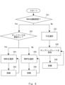
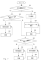
- Figure 6 shows an example of a haptic encoder selection scheme.
- the HAV data processing unit 113 determines whether the HAV data received by the reader terminal 110 is kinesthetic data (step S31).
- Kinesthetic data is data that includes data related to at least one of force, torque, or pressure. Furthermore, if the HAV data is not kinesthetic data, the HAV data is tactile data.
- Tactile data is data related to humans perceiving the surface of an object through their senses (e.g., data indicating the feel of the hand).
- the HAV data processing unit 113 determines whether the HAV data was transmitted via the first network 131 based on the selection of the encoder/decoder 114 used (step S32).
- the first network 131 is a network in which delays that would interfere with remote surgery do not occur in HAV communication.
- the second network 132 which is not the first network 131, is a network in which delays that could interfere with remote surgery may occur in HAV communication.
- the HAV data processing unit 113 selects NDHC as the encoder (step S33).
- NDHC is based on a Just Noticeable Difference (JND) encoder to reduce redundant data traffic.
- JND Just Noticeable Difference
- the HAV data processing unit 113 can train and optimize the NDHC encoder using network dynamics (step S34) to make the encoding of the HAV data more efficient.
- the network dynamics indicates the change over time of any parameter related to the communication quality of the HAV data detected by the HAV data processing unit 113 in the communication of the HAV data between the leader terminal 110 and the follower terminal 120.
- the parameters related to the communication quality include, but are not limited to, jitter, packet loss, packet errors, transmission delay, and bandwidth.
- the HAV data processing unit 113 can further train and optimize the NDHC encoder by utilizing feedback information from the network channel that is fed back to the NDHC encoder.
- the HAV data processing unit 113 selects WDHP as the encoder (step S35).
- WDHP is based on a combination of the Time-Domain Passivity Approach (TDPA) and a perceptual deadband (DB) coding scheme.
- TDPA Time-Domain Passivity Approach
- DB perceptual deadband
- TDPA encoding ensures the passivity of a two-port network, including communication channels that may cause communication failures.
- the signal transmissions on the leader and follower sides are attenuated to dissipate excess output energy, thereby supporting system stability and ensuring passivity.
- the HAV data processor 113 uses the WDHP scheme to utilize information about the network dynamics to train and optimize the encoding scheme in the presence of network delays and other signal transmission impairments (step S36). After training, the HAV data processor 113 can further train and optimize the WDHP encoder by utilizing feedback information from the network channel that is fed back to the WDHP encoder.
- the HAV data processing unit 113 selects TC (Tactile Codec) as the encoder (step S37). Haptic data has fewer communication requirements than kinesthetic data. Therefore, the HAV data processing unit 113 sets the sampling rate of TC by selecting a simple sampling scheme (step S38).
- the HAV data processor 113 also trains and optimizes the encoding scheme based on network dynamics (step S39). After training, the HAV data processor 113 can further train and optimize the TC encoder by utilizing feedback information from the network channel that is fed back to the TC encoder.
- the HAV data processing unit 113 determines whether the HAV data is kinesthetic data or haptic data, and functions as a change unit that changes the encoder used to communicate the HAV data based on the determination result.
- the HAV data processing unit 113 can select an appropriate encoder depending on the type of HAV data. Therefore, the HAV data processing unit 113 can accurately reproduce for the user the data received by the leader terminal 110, which can lead to improved QoE.
- the HAV data processing unit 113 can further determine the degree of delay that occurs in the network used for communication, and change the encoder used for communicating the HAV data based on the determined degree of delay. Therefore, the HAV data processing unit 113 can increase the accuracy with which the data received by the leader terminal 110 is reproduced for the user, leading to further improvement in QoE.
- the HAV data processing unit 113 may also perform the following process to further optimize the encoding of haptic data when network delays occur.
- FIG. 7 shows a different example of a haptic encoder selection scheme.
- the selected codec is changed depending on whether the delay is large or not. Note that the explanation of steps S31 to S34 and S37 to S39 in FIG. 7 is omitted because they are the same as those in FIG. 6. Also, in the following example, the leader terminal 110 is mainly explained, but the same processing can also be performed in the follower terminal 120.
- the HAV data processing unit 113 determines whether the transmission delay is large or not (step S40). For example, the HAV data processing unit 113 may determine whether the transmission delay is 1 ms or less, and determine that the delay is large if the delay is greater than 1 ms, and that the delay is medium if the delay is 1 ms or less. Note that a transmission delay of 1 ms or less means that the distance between the leader terminal 110 and the follower terminal 120 is approximately 150 km or less (approximately 300 km or less round trip distance).
- the HAV data processing unit 113 selects WDHC as the encoder (step S41). Furthermore, the HAV data processing unit 113 can make encoding of HAV data more efficient by training and optimizing the WDHC encoder using network dynamics (step S42). After training, the HAV data processing unit 113 can further train and optimize the WDHC encoder by utilizing feedback information from the network channel that is fed back to the WDHC encoder. Thus, the HAV data processing unit 113 can further improve the stability of remote operation on a wide area network.
- step S40 the HAV data processing unit 113 selects SEEHC as the encoder (step S43).
- SEEHC is a more preferable encoder than WDHC for solving delay issues when the transmission delay is large.
- the SE server 140 operates the second model 144 as a prediction model that supports SEEHC. This SEEHC enables the necessary functional units in the SE server 140.
- the HAV data processing unit 113 can use network dynamics to train and optimize the SEEHC encoder (step S44) to make encoding of HAV data more efficient. After training, the HAV data processing unit 113 can further train and optimize the SEEHC encoder by utilizing feedback information from the network channel that is fed back to the SEEHC encoder. Thus, the HAV data processing unit 113 can improve the stability of remote operation over a wide area network.
- the HAV data processing unit 113 can use any existing technology to determine whether a delay is occurring in the network or whether the delay that is occurring is large. For example, when HAV data is being transmitted between the leader terminal 110 and the follower terminal 120, the leader terminal 110 internally stores TFN (Time Frame Numbers) for the communication. The HAV data processing unit 113 measures the TFN at regular time intervals, for example, and detects the amount of change in the TFN to determine the occurrence and extent of a delay.
- the communication parameter that the HAV data processing unit 113 uses for the determination is not limited to the TFN.
- steps S33, S38, and S41 relate to network coding.
- step S43 is not the only step in which the necessary functional units in the SE server 140 are enabled.
- the SE server 140 can predict at least one of the network parameters or the user's behavior using at least one of the first functional unit 141 or the second functional unit 142.
- the follower terminal 120 can also execute processing similar to that shown in Figs. 6 and 7.
- the SE server 140 can also predict at least either the network parameters or the haptic data generated on the robot side, using at least either the first functional unit 141 or the second functional unit 142.
- the HAV data processing unit 113 may determine the encoder selection scheme shown in FIG. 6 or FIG. 7 using a trained model trained by using data including information indicating the type of HAV data and the degree of delay, and the corresponding encoder type (correct label) as training data.
- the SEEHC header transmitted from the transmitting unit (not shown) of the leader terminal 110 or the follower terminal 120 to the SE server 140 will be described.
- the HAV data processing unit 113 or the HAV data processing unit 123 generates and transmits a SEEHC header according to the selection result.
- the SE server 140 can operate the second model 144 and make predictions regarding the user or robot. Note that even if an encoder other than SEEHC is selected in FIG. 7, the leader terminal 110 or the follower terminal 120 can transmit a SEEHC header according to the selection result to the SE server 140.
- the HAV data processing unit 113 or the HAV data processing unit 123 can attach any type of SEEHC header shown below to the HAV data and transmit the HAV data to which the SEEHC header is attached.
- the leader terminal 110 is mainly described, but similar processing can also be performed on the follower terminal 120.
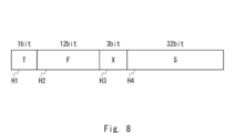
- FIG. 8 shows a specific example of a SEEHC header (codec header) that is used when the HAV data is kinesthetic data and it is determined in step S32 of FIG. 7 that there is no delay.
- the SEEHC header includes a T field H1, an F field H2, an X field H3, and an S field H4.
- the bit size of each field corresponds to delay information in the system.
- the delay information indicates, for example, whether or not there is a delay in the system.
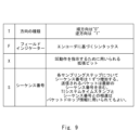
- FIG. 9 is a table explaining the SEEHC header coding corresponding to FIG. 8.
- the example of the SEEHC header shown in FIG. 9 is used when the HAV data received by the leader terminal 110 in FIG. 7 is kinesthetic data (Yes in step S31).
- the SEEHC header shown in FIG. 9 can be used regardless of the presence or absence of delay and the degree of delay.
- the X field H3 in FIG. 9 is the most important, as it is used to instruct advanced operations of the SE server 140. The configuration of each field will be explained in detail below with reference to FIG. 9.
- the T field H1 is 1 bit long and indicates the type of traffic flow direction.
- the F-field H2 is a syntax based on the encoder. Specifically, the F-field H2 contains details of the haptic data and is composed of 12 bits when there is no delay. The F-field H2 includes 3 bits for position, 3 bits for direction, 3 bits for velocity, and 3 bits for angular velocity. If there is no data related to force, the leader terminal 110 may fill the bit fields of the F-field H2 with 0 (zero). Note that the leader terminal 110 generates the F-field H2 based on data acquired from a sensor of the leader terminal 110 (e.g., a sensor attached to the user).
- a sensor of the leader terminal 110 e.g., a sensor attached to the user.
- the X field H3 is an extension bit used to indicate the function to be executed by the SE server 140.
- the X field H3 is 3 bits long.
- the HAV data processing unit 113 evaluates the QoE acquired by the QoE acquisition unit 115, and judges whether the QoE meets the required criteria. Based on the result of this judgment, the X field H3 is set to enable or disable the functions of the first functional unit 141 and the second functional unit 142 of the SE server 140. A detailed flow of this will be described later. Depending on the presence or absence of a transmission delay, or the degree of the delay, as judged in FIG. 7, the HAV data processing unit 113 can change and set the X field H3.
- the S field H4 is 32 bits long and contains the sequence number set by the leader terminal 110 when it transmits a packet of HAV data.
- the sequence number increases by one for each sampling step.
- the packet transmitted from the leader terminal 110 contains the latest sequence number.
- the difference between the TI system timestamp and the sequence number may be used for packet drop information.
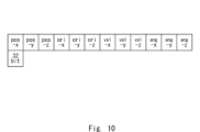
- FIG. 10 shows an example of the payload structure used in the SEEHC header in FIG. 8.
- FIG. 10 shows the payload structure of a forward bit stream.
- the payload is composed of fields for position data (pos-x, pos-y, pos-z), direction data (ori-x, ori-y, ori-z), velocity data (vel-x, vel-y, vel-z), and angular velocity data (ang-x, ang-y, ang-z), each of which indicates data in three-dimensional directions.
- the length of each field in the payload is 32 bits.
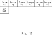
- FIG. 11 shows an example of the payload configuration of a feedback bit stream corresponding to the forward bit stream corresponding to FIG. 10.
- the feedback bit stream is composed of force data (force-x, force-y, force-z) and torque data (torque-x, torque-y, torque-z) each indicating data in three-dimensional directions.
- the length of each field in the feedback bit stream is 32 bits.
- the leader terminal 110 when a user of the leader terminal 110 performs an action, instructions regarding the action are transmitted from the leader terminal 110 to the follower terminal 120 as a forward bit stream as shown in FIG. 10.
- the follower terminal 120 controls a surgical robot connected to the follower terminal 120 based on the received instructions.
- the follower terminal 120 transmits data related to the force detected by a sensor provided on the robot to the leader terminal 110 as a feedback bit stream as shown in FIG. 11. Note that this feedback bit stream is transmitted directly from the follower terminal 120 to the leader terminal 110 if there is no transmission delay.
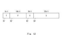
- FIG. 12 shows a specific example of a SEEHC header (codec header) that is used when the HAV data is kinesthetic data and it is determined in step S32 of FIG. 7 that there is a delay.
- the SEEHC header includes a T field H1', an F field H2', an X field H3', and an S field H4'. Below, for each field in FIG. 12, differences from FIG. 8 will be particularly described, and descriptions of commonalities with FIG. 8 will be omitted as appropriate.
- T field H1' is the same as T field H1 in Figure 8, so the explanation is omitted.
- the F-field H2' is a syntax based on the encoder. Specifically, the F-field H2' contains details of the haptic data and consists of 18 bits in the case of delay.
- the F-field H2' includes 3 bits for position, 3 bits for direction, 3 bits for velocity, and 3 bits for angular velocity.
- 6 bits are available in the F-field H2' for haptic/energy information corresponding to each dimension of the haptic data for TDPA.
- the haptic/energy information is information about at least one of haptic and energy.
- the haptic/energy information is used to control the codec in case of delay.
- the haptic/energy information is also used in the TDPA encoding process to prevent unexpected changes in data due to interference in the communication path. In this way, the energy level is minimized, and the system stability and passivity of the communication link are guaranteed. If there is no force-related data, the reader terminal 110 may fill the bit fields of the F-field H2' with 0 (zero
- the X field H3' is an extension bit used to indicate the function to be executed by the SE server 140.
- the X field H3 is 5 bits in length.
- the HAV data processing unit 113 sets the X field H3' to enable or disable the functions of the first functional unit 141 and the second functional unit 142 of the SE server 140 based on the QoE evaluation.
- the S field H4' is 32 bits long and contains the sequence number etc. set by the leader terminal 110 when sending the HAV data packet.
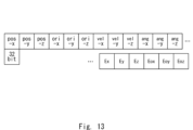
- Figure 13 shows an example of the payload structure used in the SEEHC header in Figure 12.
- Figure 13 shows the payload structure of a forward bit stream.
- the payload in Figure 13 includes additional information on translational energy (Ex, Ey, Ez) and rotational energy (Eox, Eoy, Eoz), which each indicate data in three-dimensional directions.
- the payload field length is 32 bits.
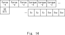
- Figure 14 shows an example of the payload configuration of a feedback bitstream corresponding to the forward bitstream corresponding to Figure 13.
- the feedback bitstream contains additional information regarding translational energies (Ex, Ey, Ez) and rotational energies (Eox, Eoy, Eoz), each of which indicates data in three dimensional directions.
- the new energy data for translational and rotational energy shown in Figures 13 and 14 is used in TDPA to level the output energy to maintain system stability and communication link passivity during remote operation when using a wide area network with delay. In this way, by adding information about the energy for controlling the codec to the SEEHC header, it becomes possible to maintain system stability and communication link passivity during remote operation.
- SEEHC takes advantage of the presence of SE server 140 in TI during remote operation and defines specific operations of SE server 140. Combining SE server 140 with SEEHC enhances TI functions. This improves and guarantees QoE in wide area networks, and supports low network latency in remote operation over distances of several hundred kilometers or more.
- SEEHC defines the bits within the SEEHC frame.
- the bits in the X field in particular are important as they define the operation of the SE server 140. As mentioned above, when there is no network delay, the bit size of the X field is 3 bits, but when there is a network delay, the bit size of the X field is 5 bits.
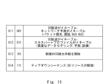
- FIG. 15 is a table showing actions associated with the SEEHC scheme when there is no delay.
- FIG. 15 shows an example of an X field with a bit size of 3 bits in the SEEHC header of FIG. 8. Below are examples of each action shown in FIG. 15.
- X11 When the X field is X11, i.e. "001", forwarding to the SE server 140 is enabled. Therefore, the leader terminal 110 transmits the HAV data that it had been transmitting to the follower terminal 120 to the SE server 140 instead of the follower terminal 120.
- X11 also indicates that the network prediction performed by the first functional unit 141 of the SE server 140 is enabled.
- the network prediction is, for example, a prediction regarding at least one of packet loss, transmission delay, QoS, QoE, and the like.
- X11 When the X field is X12, i.e. "011", transfer to the SE server 140 is enabled. Therefore, the leader terminal 110 transmits the HAV data that was previously transmitted to the follower terminal 120 to the SE server 140 instead of the follower terminal 120.
- X11 also indicates that the prediction (expert profile) of human behavior or haptic data acquired by a robot, performed by the second function unit 142 of the SE server 140, is enabled. This allows for advanced data modeling, prediction, and training. Then, the second function unit 142 performs the prediction and controls the HAV communication, thereby reducing packet loss and transmission delays, and improving QoS, QoE, etc.
- X11 corresponds to (B) in the first embodiment.
- X13 When the X field is X13, i.e., "101", it indicates that a procedure for detecting a new SE server 140 is being started. Determining a new SE server 140 may indicate that a new SE server 140 is being determined to control communications between the leader terminal 110 and the follower terminal 120 in a state in which the SE server 140 is not currently involved in the communications between the leader terminal 110 and the follower terminal 120. Alternatively, determining a new SE server 140 may indicate that a different SE server from the SE server currently controlling communications between the leader terminal 110 and the follower terminal 120 is being made to control communications. X13 is required, for example, when at least one of a QoS or QoE failure occurs on either the leader side or the follower side of the remote operation, and another SE with higher system resources may be required.
- the leader terminal 110 or the follower terminal 120 can have the new SE server 140 control the communications by sending a request including X13.
- the first functional unit 141 or the second functional unit 142 of the SE server 140 that receives the request starts controlling the communications of the HAV data in response to the request.
- the SE server that controls the communications can be changed from an unselected state to a selected state, or the SE server that controls the communications can be changed to a state where an SE server that can improve QoE, etc. is selected, thereby making it possible to improve the communications performance of the HAV data.
- X field is X14, or "111"
- the leader terminal 110 or the follower terminal 120 can release the resources of the SE server 140 that was being used by sending a trigger including X14 to that SE server 140.
- the first functional unit 141 or the second functional unit 142 of the SE server 140 releases the resources in response to the trigger.
- the SE server 140 is able to execute control of other communications, making it possible to improve communication performance not only between the leader terminal 110 and the follower terminal 120 but also throughout the entire network.
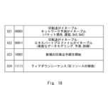
- FIG. 16 is a table showing actions related to the SEEHC scheme when there is a delay.
- FIG. 16 shows an example of an X field with a bit size of 5 bits in the SEEHC header of FIG. 12.
- the X field in FIG. 16 is X21, i.e., "00001”
- the X field in FIG. 16 is X22, i.e., "00011”
- it corresponds to when the X field in FIG. 15 is X12, i.e., "011”.
- the X field in FIG. 16 is X23, i.e., "10001”
- the SE server 140 For remote operation in the presence of delays, the SE server 140 needs to enable additional features to support a high level of QoE.
- the SE server 140 needs to be instructed to perform specific functions to reduce transmission delays, increase the QoE level, and maintain system stability (passivity of the communication link).
- the leader terminal 110 identifies the SEEHC by utilizing the X field shown in Figure 16.
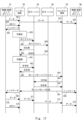
- FIG. 17 is a sequence diagram showing the SE server detection procedure started and executed by the leader terminal.
- a wide-area remote operation system is shown that includes a leader-side physical/virtual endpoint D1, a leader terminal D2, an SE server (1) D3, an SE server (n) D4, a follower terminal D5, and a follower-side physical/virtual endpoint D6.
- the leader terminal D2, the follower terminal D5, the SE server (1) D3, and the SE server (n) D4 correspond to the leader terminal 110, the follower terminal 120, and the SE server 140 in FIG. 5, respectively.
- the physical/virtual endpoint D1 corresponds to at least one of the physical environment 111 or the virtual environment 112 in FIG.
- the physical/virtual endpoint D6 corresponds to at least one of the physical environment 121 or the virtual environment 122 in FIG. 5.
- the physical/virtual endpoints D1 and D2 may be mounted on the leader terminal D2 and the follower terminal D5, respectively.
- the physical/virtual endpoints D1 and D2 may be separate devices from the leader terminal D2 and the follower terminal D5, respectively, and may be devices connected to the leader terminal D2 and the follower terminal D5.
- multiple SE servers, n in number are provided. The detection procedure will be described below with reference to FIG. 17.
- the physical/virtual endpoint D1 transmits the QoE performance (hereinafter also referred to as QoE(L)) on the leader side to the leader terminal D2 (step S54).
- the physical/virtual endpoint D1 notifies the leader terminal D2 that the QoE(L) does not meet the required standard. This notification is made, for example, by the user performing the remote operation operating the input unit of the physical/virtual endpoint D1.
- the leader terminal D2 starts detecting the SE server in response to the received notification, and transmits an indicator to the physical/virtual endpoint D1 notifying it that SE server detection has started (step S55). By transmitting this indicator, for example, processing such as stopping further data transmission from the physical/virtual endpoint D1 until the SE server is detected is performed.
- the leader terminal D2 starts the SE server detection process (step S56).
- the leader terminal D2 sends an SE server request (hereinafter also referred to as SE request) to all SE servers to which the leader terminal D2 can connect, including SE server (1) D3 and SE server (n) D4 (steps S57, S58).
- SE request has an SEEHC header including an X13 or X23 field, which means that a new SE server detection procedure is being started.
- the SE request is sent to candidates for SE servers that will execute control related to communications.
- SE server (1) D3 and SE server (n) D4 receive the SE request and send a response (hereinafter also referred to as SE response) to the leader terminal D2 (steps S59, S60).
- the leader terminal D2 selects an optimal SE server from among the SE servers that received the SE response, in place of the currently selected SE server, based on all the information necessary to select the optimal SE server (step S61).
- the leader terminal D2 may select the SE server that is closest to the leader terminal D2 on the communication path. However, the closest SE server may be in a busy state or may be under a high load. In that case, another SE server that can provide the necessary resources, such as the system load, the latency requirements of the HAV data, and the stability of the communication link, may be selected.
- the leader terminal D2 identifies an SE server that can provide the necessary resources according to the contents of the received SE response, and selects the identified SE server.
- the leader terminal D2 selects SE server (1) D3 as the optimal SE server
- the leader terminal D2 transmits a request to reserve resources (hereinafter also referred to as SE reservation) to the selected SE server (1) D3 (step S62).
- SE reservation a request to reserve resources
- the SE server (1) D3 checks whether there are any available resources in its own device.
- the SE server (1) D3 confirms that there are available resources, and transmits an SE response indicating that there are available resources to the leader terminal D2 (step S63).
- the leader terminal D2 In response to receiving the SE response from the SE server (1) D3, the leader terminal D2 notifies the follower terminal D5 of the selection of the SE server (1) D3 as the new SE server and transmits an SE handover request to execute a handover of the SE server (step S64).
- the follower terminal D5 transmits an SE reservation to the SE server (1) D3 indicated in the SE handover request (step S65).
- the SE server (1) D3 transmits an SE response to the follower terminal D5 (step S66).
- the follower terminal D5 which has received the SE response, transmits a handover response to the leader terminal D2 indicating that handover of the SE server is possible (step S67).
- the follower terminal D5 also notifies the physical/virtual endpoint D6 of an indicator indicating that the SE server to be used will be switched to SE server (1) D3 (selection result) (step S68).
- the leader terminal D2 which has received the handover response, recognizes that the SE server to be used can be switched to SE server (1) D3.
- the leader terminal D2 then notifies the physical/virtual endpoint D1 of an indicator indicating that the SE server to be used will be switched to SE server (1) D3 (step S69).
- the physical/virtual endpoint D1 resumes sending data related to remote operation to the leader terminal D2 (step S70).
- the leader terminal D2 transfers the received data to the selected SE server (1) D3 (step S71).
- the SE server (1) D3 analyzes the received data using a model held by the SE server and modifies the data. The details of this analysis and modification process are as described above.
- the SE server (1) D3 transmits the modified data to the follower terminal D5 (step S72).
- the follower terminal D5 transmits the received data to the physical/virtual endpoint D6 that is the target of the remote operation session (step S73).
- the data related to remote operation is modified by the operations up to this point and then transmitted to the physical/virtual endpoint D6.
- remote operation is performed as instructed by the user of the physical/virtual endpoint D1 and with adjustments made suitable for remote operation.
- the physical/virtual endpoint D1 transmits the QoE(L) to the leader terminal D2 (step S74).
- the physical/virtual endpoint D1 notifies the leader terminal D2 that the QoE(L) meets the required criteria. Therefore, the selection of a new SE server is not performed, and the selection of the SE server performed up to step S69 is completed. In other words, the remote operation between the physical/virtual endpoints D1 to D6 continues using the settings performed up to step S69. If the QoE(L) no longer meets the required criteria, the SE server selection process similar to that shown in steps S54 to S69 is started again.
- the leader terminal D2 may transmit to the SE server (1) D3, as a trigger to release the resources, an SEEHC header including a field X14 or X24 instructing the SE server (1) D3 to release the resources.
- steps S54 to S69 may be executed not only when a new SE server is selected, but also when at least one of the first functional unit 141 and the second functional unit 142 in an already selected SE server is enabled, disabled, or the settings are switched. In other words, this process may be executed when any change occurs in the method of controlling HAV communication based on at least one of the network parameters or predictions regarding humans or robots.
- FIG. 18 is a sequence diagram showing the SE server detection procedure that is initiated and executed by a follower terminal.
- the components of the remote control system shown in FIG. 18 are the same as those shown in FIG. 17. The detection procedure is explained below with reference to FIG. 18.
- the physical/virtual endpoint D1 transmits data related to the remote operation to the leader terminal D2 (step S81).
- the leader terminal D2 transfers the received data to the follower terminal D5 (step S82).
- the follower terminal D5 transfers the received data to the physical/virtual endpoint D6 that is the target of the remote operation session (step S83).
- the data related to the remote operation is transmitted to the physical/virtual endpoint D6, and the remote operation instructed by the user of the physical/virtual endpoint D1 is performed on the physical/virtual endpoint D6 side.
- the physical/virtual endpoint D6 transmits the QoE performance (hereinafter also referred to as QoE(F)) on the follower side to the follower terminal D5 (step S84).
- the physical/virtual endpoint D6 notifies the follower terminal D5 that the QoE(F) does not meet the required standard.
- This notification is made, for example, by a sensor on the follower side robot that is performing the instructed remote operation on-site detecting the QoE(F).
- this notification may be made by a user on the follower terminal D5 side operating the input unit of the physical/virtual endpoint D6.
- the follower terminal D5 starts detecting the SE server in response to the received notification, and transmits an indicator to the physical/virtual endpoint D6 notifying it that SE server detection has started (step S85). By transmitting this indicator, for example, processing such as stopping further data transmission from the physical/virtual endpoint D6 until the SE server is detected is performed.
- follower terminal D5 starts the SE server detection process (step S86).
- Follower terminal D5 sends an SE request to all SE servers to which follower terminal D5 can connect, including SE server (1) D3 and SE server (n) D4 (steps S87, S88).
- This SE request may have an SEEHC header including an X13 or X23 field, which indicates that a new SE server detection procedure is being started.
- SE server (1) D3 and SE server (n) D4 receive the SE request and send an SE response in response to it to follower terminal D5 (steps S89, S90).
- the follower terminal D5 selects the optimal SE server from among the SE servers from which the SE response was received, in place of the currently selected SE server (step S91). Details of the selection of the SE server by the follower terminal D5 are as explained in step S61.
- the follower terminal D5 selects the SE server (1) D3 as the optimal SE server
- the follower terminal D5 transmits an SE reservation to reserve resources to the SE server (1) D3 to be selected (step S92).
- the SE server (1) D3 checks whether there are any available resources in its own device.
- the SE server (1) D3 confirms that there are available resources, and transmits an SE response indicating that there are available resources to the follower terminal D5 (step S93).
- the follower terminal D5 In response to receiving the SE response from the SE server (1) D3, the follower terminal D5 notifies the leader terminal D2 of the selection of the SE server (1) D3 as the new SE server and transmits an SE handover request to execute a handover of the SE server (step S94).
- the leader terminal D2 transmits an SE reservation to the SE server (1) D3 indicated in the SE handover request (step S95).
- the SE server (1) D3 transmits an SE response to the leader terminal D2 (step S96).
- the leader terminal D2 which has received the SE response, transmits a handover response to the follower terminal D5 indicating that handover of the SE server is possible (step S97).
- the leader terminal D2 also notifies the physical/virtual endpoint D1 of an indicator indicating that the SE server to be used will be switched to SE server (1) D3 (selection result) (step S98).
- the follower terminal D5 which has received the handover response, recognizes that the SE server to be used can be switched to SE server (1) D3.
- the follower terminal D5 then notifies the physical/virtual endpoint D6 of an indicator indicating that the SE server to be used will be switched to SE server (1) D3 (step S99).
- the physical/virtual endpoint D1 resumes sending data related to remote operation to the leader terminal D2 (step S100).
- the leader terminal D2 transfers the received data to the selected SE server (1) D3 (step S101).
- the SE server (1) D3 analyzes the received data using a model held by the SE server and modifies the data. The details of this analysis and modification process are as described above.
- the SE server (1) D3 transmits the modified data to the follower terminal D5 (step S102).
- the follower terminal D5 transmits the received data to the physical/virtual endpoint D6 that is the target of the remote operation session (step S103).
- the data related to remote operation is modified by the operations up to this point and then transmitted to the physical/virtual endpoint D6.
- remote operation is performed as instructed by the user of the physical/virtual endpoint D1 and with adjustments made suitable for remote operation.
- the physical/virtual endpoint D6 transmits the QoE (F) to the follower terminal D5 (step S104).
- the physical/virtual endpoint D6 notifies the follower terminal D5 that the QoE (F) meets the required criteria. Therefore, the selection of a new SE server is not performed, and the selection of the SE server performed up to step S99 is completed. In other words, the remote operation between the physical/virtual endpoints D1 to D6 continues using the settings performed up to step S69. If the QoE (F) no longer meets the required criteria, the SE server selection process similar to that shown in steps S84 to S99 is started again.
- the follower terminal D5 may transmit to the SE server (1) D3, as a trigger to release the resources, an SEEHC header including a field X14 or X24 instructing the SE server (1) D3 to release the resources.
- steps S84 to S99 may be executed not only when a new SE server is selected, but also when at least one of the first functional unit 141 and the second functional unit 142 in an already selected SE server is enabled, disabled, or the settings are switched. In other words, this processing may be executed when any change occurs in the method of controlling HAV communication based on at least one of the network parameters or predictions regarding humans or robots.
- SE-EPS SE Expert Profile Selection
- expert profiles and templates initiated by the SE server 140 can be used to train the second model 144 of the SE server 140 to further optimize the QoE in teleoperation.
- the SE-EPS scheme supports performing haptic prediction such that the transmission delay is less than 1 ms when the prediction error is minimized.
- the SE-EPS scheme is a learning-by-demonstration approach in which a haptic sensing robot operated by teleoperation at the follower terminal 120 side acquires skills without being explicitly programmed.
- a hidden Markov model (HMM) is used for offline training by encoding the force and torque data and related parameters. Once the HMM is trained, a generalized profile can be extracted. HMMs are useful for predicting forward and feedback information that may be lost during data transmission over wide area networks.
- FIG. 19 is an image diagram showing training of the SE server 140 using an expert profile.
- the HMM may be trained by multiple experts.
- the expert E2 uses such objects to create an expert profile E3.
- the expert E2 uses the expert profile E3 to train the SE of the SE server E4. This makes the SE a trained agent, and the accuracy of the model is improved.
- the trained SE server E5 contributes to reducing transmission failures and delays by making predictions regarding the network and/or humans and/or robots.
- each object E11 there may be multiple objects E11 in the physical/virtual world E1, and each object E11 may be different. If each object E11 is different, then each object E11 requires a dedicated trainer E12 for training. As a result of training by the trainer E12, a different profile E13 is created for each object E11. For example, a surgeon can generate a remote operation profile E13 by using the dedicated trainer E12. A data profile related to the remote operation is also generated.
- position, direction, force and torque information is generated, and a set of data profiles is encoded by the HMM.
- the encoded data profiles are then sent to the SE E14.
- the generalized model is then reproduced during the online session by the trained SE E15.
- the profile E13 described above may be created, for example, outside the SE server 140 (for example, the leader terminal 110 or the follower terminal 120).
- the created profile E13 is input to the SE server E4, whereby the SE of the SE server E4 is trained.
- This training is performed, for example, when the SE server 140 is in passive mode (i.e., when at least one of the first model 143 and the second model 144 is not used).
- the SE server 140 is in active mode, i.e., when at least one of the first model 143 and the second model 144 is used, the above training may be performed as online training.
- the HMM is used to encode a set of force, torque and velocity data into a set of profiles.
- Gaussian Mixture Regression (GMR) can be used by the SE server E4 to support online remote operation sessions.
- GMR Gaussian Mixture Regression
- the SE server E4 can provide predicted data to the follower terminal 120 in case the leader terminal 110 data is lost or delayed. In this scenario, the transmission delay can be kept below 1 ms and the lost data can be restored.
- This HMM/GMR model is used to predict remote haptic feedback information, thereby reducing the error rate over a wide area network with prediction times of less than 1 ms.
- Multimodal data includes, for example, HAV data.
- Wide area networks have long wired and wireless connection links, which can adversely affect user experience.
- User experience is of high importance and is measured as QoE.
- Current remote control systems have limited scope of application and insufficient QoE in wide area networks. Therefore, remote control is mainly performed over short distances, such as within the same room or building, but is difficult to perform over long distances, such as between municipalities or countries.
- the user may face challenges such as delay or loss of HAV data due to the deterioration of QoE, which may cause the network to lose reliability.
- the communication link between the leader and followers does not affect remote control and can support system stability. For example, even when performing remote control over a long distance, such as between different municipalities or countries, it is desirable to have a state in which the QoE is indistinguishable or nearly indistinguishable from that of performing local remote control within the same room or building.
- the communication path (e.g., a path in a wireless connection such as 5G or 6G) should not interfere with the remote control itself.
- the remote control endpoint e.g., a leader terminal or a follower terminal
- the remote control endpoint is a very complex system including sensors, actuators, motors, springs, and dampers. Therefore, data transmission through the communication path may affect the stability of the system not only on the follower side but also on the leader side. For this reason, the remote control system needs to guarantee the system stability of the entire system.
- guaranteeing this system stability is a requirement that is difficult to achieve on a wide-area communication network. Specifically, data transmission on a wide-area network such as 5G or 6G may cause an unwanted increase in energy or a change in system impedance.
- Haptic data communication requires network latency of about 1 ms to properly control physical machines and virtual environments from remote locations.
- network latency of about 1 ms to properly control physical machines and virtual environments from remote locations.
- Technical constraints include not only latency in the wireless interface but also latency in the wired backbone network.
- Physical constraints result from the limited speed of light, which causes latency in wide area networks and limits the distance over which the network can be applied.
- haptic data includes different types of data: kinesthetic data and/or tactile data.
- Kinesthetic data includes data related to force, torque and pressure. These data are highly susceptible to transmission delays, jitter and packet loss. A delay or loss in the data signal can result in an event that is not perceptible to human perception. Furthermore, delays in kinesthetic data can lead to incorrect or delayed decision-making by human perception, i.e. the human brain. Even if a human senses kinesthetic data, which is an important signal, it may be ignored if the data reaches the human with a delay.
- Haptic data is data that allows humans to sense the surface of an object through their senses. Such data is less susceptible to transmission delays.
- audio and video data are combined with haptic data, synchronization of the haptic data, audio data and video data is important to achieve a high level of QoE. Therefore, it is important that HAV data transmission is supported with high network bandwidth, low latency and low jitter times.
- the remote control system 100 can reduce the transmission latency of HAV data over a wide area network such as 5G (e.g., 5G Advanced) or 6G, for example, having a distance of 100 km or more. Therefore, it is possible to support haptic applications such as remote control.
- 5G e.g., 5G Advanced
- 6G 6G
- the network of the remote control system 100 switches data traffic between the leader terminal and the follower terminals, thereby supplying data to an SE that provides a function of improving QoE for remote users, thereby achieving the above effect.
- the SE has an internal module (first functional unit 141) that predicts network parameters, and an internal module (second functional unit 142) that makes predictions about the user or robot.
- the SE can improve traffic quality and make the system in which remote control is realized more stable by predicting network parameters using the first functional unit 141.
- the SE can predict human behavior using the second functional unit 142, and instantly feed back predicted user behavior or information on haptic data acquired by the robot to the remote control system before new system data is transmitted to the SE. Therefore, the SE can improve QoE on a wide area network without being affected by network delays.
- the terminal in embodiment 2 can identify whether an SE server exists and whether such an SE server can support a remote control session.
- the SE server then supports the remote control session by receiving HAV data from the leader terminal and forwards the HAV data to the follower terminal.
- the SE server can also support the remote control session by receiving HAV data from the follower terminal and forward the HAV data to the leader terminal.
- the SE server has several modes: (1) The SE server can be in a passive mode in which it does not modify the HAV data received from the leader terminal and transfers the HAV data from the leader terminal to the follower terminals. In this passive mode, the second function unit 142 of the SE server is disabled, so that the SE server does not perform predictions about users or robots.
- the SE server When the SE server receives HAV data from the leader terminal, it can also be in an active mode in which it modifies the HAV data and transfers the modified data to the follower terminal. In this active mode, the second functional unit 142 of the SE server is active, so the SE server makes predictions about the user or robot and modifies the received HAV data based on the prediction results.
- the SE server can also apply additional functions and techniques, such as prediction, to the data being sent and received. This prediction allows the SE to improve QoE performance.
- the SE server can use trained expert models, network predictions, or additional encoding schemes to predict human actions or haptic data acquired by a robot, further reducing network latency or improving overall QoE performance.
- the SE server can obtain advanced prediction models by performing training using the SE-EPS.
- the first functional unit 141 of the SE server 140 may be enabled or disabled.
- the SE server 140 can improve the data transmission performance (or the accuracy of the network prediction) by predicting network parameters.
- the first functional unit 141 and the second functional unit 142 of the SE server 140 can be individually set to enable or disable the functions as needed.
- either the first functional unit 141 or the second functional unit 142 of the SE server 140 may be set to enable, or both may be set to enable.
- SEs with different functions such as prediction, remote rendering, or computation outsourcing may be provided in the network.
- Each SE may provide a unique set of functions to be used during a remote operation session.
- a specific SE selection procedure is described for selecting the most appropriate SE.
- This SE selection is part of an encoding scheme for indicating the internal functions of the selected SE server 140.
- the SEEHC indicates the SE regarding the prediction functions and provides data fields for setting the functions on the SE, leader, and follower side.
- devices with low power consumption and functions such as remote rendering and computation outsourcing can be provided in the network as SEs. Therefore, even if the functions in the network are expanded, the increase in power consumption required for the network can be suppressed.
- FIG. 20 is a diagram showing the effects of the present disclosure.
- the leader terminal 110 is connected to the follower terminal 120 via the SE server 140.
- the configurations of the leader terminal 110 and the follower terminal 120 are as shown in FIG. 5, and description thereof will be omitted.
- the SE server 140 also includes a rendering/modeling unit 14A, a prediction unit 14B, and an interface 14C.
- the rendering/modeling unit 14A is a functional unit collectively referring to the first functional unit 141 and the second functional unit 142
- the prediction unit 14B is a functional unit collectively referring to the first model 143 and the second model 144.
- the interface 14C also corresponds to the interface 145.
- the leader terminal 110 has a coverage area (hereinafter also referred to as area A) in which data transmission from the leader terminal 110 is possible, which is determined by a data connection link LA (hereinafter also referred to as link LA).
- area A a coverage area in which data transmission from the leader terminal 110 is possible
- link LA (hereinafter also referred to as link LA).
- link LA crosses horizon HA, which is the boundary of area A
- link A becomes unstable, lossy, or has delays.
- the QoE (L) of the leader terminal 110 In the area beyond the horizon HA from the leader terminal 110, it is not realistic to use the QoE (L) of the leader terminal 110 for the QoE adjustment function, which is a function of link LA.
- FIG. 20 the fact that QoE (L) cannot be used for the QoE adjustment function in the area beyond the horizon HA is shown as event F1.
- the follower terminal 120 has a coverage area (hereinafter also referred to as area B) in which data transmission from the follower terminal 120 is possible, which is determined by the data connection link LB (hereinafter also referred to as link LB).
- area B the data connection link LB
- link LB the data connection link LB
- link LB crosses horizon HB, which is the boundary of area B
- link B becomes unstable, has high loss, or experiences delays.
- the QoE (F) of the follower terminal 120 it is not realistic to use the QoE (F) of the follower terminal 120 for the QoE adjustment function, which is a function of link LB.
- event F2 the fact that QoE (F) cannot be used for the QoE adjustment function in the area beyond horizon HB is shown as event F2.
- the leader terminal 110 obtains not only the QoE(L) but also the QoE(F) at the follower terminal 120 and detects the difference between the QoE(L) and the QoE(F). For example, if the detection result indicates a network failure, the leader terminal 110 starts negotiation with the SE server 140 to select a new SE server 140. If the link LB exceeds the horizon HB, the follower terminal 120 can perform the same process instead of the leader terminal 110. In this way, it is possible to perform a determination of the network performance at both the leader terminal 110 and the follower terminal 120. This enables predictive models, outsourced rendering, or modeling.
- the SE Server 140 supports remote operations over wide area networks by predicting network performance metrics and human activity, thereby ensuring the required latency parameters and enabling life-critical operations such as remote surgery. Thus enabling stable and reliable TI for HAV application scenarios. Furthermore, high reliability and low latency communication for smart factors, industrial Internet-of-Things (IoT) and telemedicine.
- IoT Internet-of-Things
- the present disclosure may be fully embodied as a V2V (Virtual to Virtual) environment in which a communication link including an SE becomes a network.
- V2V Virtual to Virtual
- human behavior and the acquisition of that behavior data may be performed in a virtual space using Google Glass (registered trademark) or HoloLens (registered trademark), etc.
- the leader terminal transmits data regarding the behavior, etc. performed in the virtual space to the follower terminal, and at that time, the SE server can predict human behavior, etc. Therefore, the SE server can provide data at any time when lost data occurs.
- the SE server can also fully render an entire session based only on basic data input from the leader terminal. This is interesting for multi-game operations, since the expendable and costly rendering of graphics can be managed by the SE server. For example, Finite Element Method simulations and 3D (Three Dimensions) rendering require powerful Graphical Units (GPUs). GPUs can be stored in large quantities on the SE server, like a so-called rendering farm, allowing the SE server to perform rendering in multi-game operations, etc. The disclosed system can therefore be applied in outsourced graphical rendering applications, including AI graphical rendering models, and monetized.
- the servers and terminals described in each embodiment of this disclosure are applicable to remote medical care, remote surgery, remote robotic surgery, robotic surgery, etc., for the purpose of, for example, biopsy, injection, neurosurgery, or cancer treatment, but the applications are not limited to these.
- This disclosure is used, for example, for emulation between a human and a machine located at a distance, using a reinforcement learning unit supervised for remote operation.
- Ultra-low latency wide area network support enables secure remote operation across large distances over wide area communication networks for applications such as proactive healthcare, industrial automation, intelligent transportation, and surveillance for defense and disaster management.
- the remote location communications disclosed herein enables a number of edutainment applications and immersive human experiences via remote machines, including immersive virtual/augmented reality (VR/AR).
- the disclosure also enables immersive control and manipulation of real and virtual objects and machines.
- An AI-enhanced server on the access network enables prediction of haptic manipulation, including offline expert training and online simulation of haptic manipulation using haptic recognition, kinesthetic recognition, or tactile recognition.
- the present disclosure can support remote master and replica pair control, including sensing and control of real and virtual machines and robots, as well as predictive HAV data.
- the present disclosure can also support haptic internet applications, including smart factories and smart logistics.
- At least one of the terminals or servers shown in each embodiment is realized by one or more computers.
- the method of distributing each part of the terminal or server among the multiple computers is arbitrary.
- Some or all of the components of the terminal or server may be provided in a cloud server constructed on the cloud, or in other types of virtualized servers generated using virtualization technology, etc. Functions other than those provided in servers such as cloud servers or virtualized servers are placed at the edge. For example, in a wide area network that realizes remote surgery, the edge is a device placed at or near the site of the surgery.
- this disclosure has been described as a hardware configuration, but this disclosure is not limited to this.
- the processes or steps executed by at least any of the terminals, management servers, and SE servers described in the above embodiment may be realized by having a processor in a computer execute a computer program.
- FIG. 21 is a block diagram showing an example of the hardware configuration of an information processing device in which the processing of the device in each of the above-described embodiments is executed.
- this information processing device 90 includes a signal processing circuit 91, a processor 92, and a memory 93.
- the signal processing circuit 91 is a circuit for processing signals according to the control of the processor 92.
- the signal processing circuit 91 may also include a communication circuit for receiving signals from a transmitting device.
- the processor 92 is connected or coupled to the memory 93, and performs the processing of the device described in the above-mentioned embodiment by reading and executing software or computer programs from the memory 93.
- Examples of the processor 92 include a CPU (Central Processing Unit), an MPU (Micro Processing Unit), an FPGA (Field-Programmable Gate Array), a DSP (Demand-Side Platform), and an ASIC (Application Specific Integrated Circuit).
- a single processor may be used as the processor 92, or multiple processors may be used in cooperation with each other.
- Memory 93 may be composed of volatile memory, non-volatile memory, or a combination of both.
- the volatile memory may be, for example, a RAM (Random Access Memory) such as DRAM (Dynamic Random Access Memory) or SRAM (Static Random Access Memory).
- the non-volatile memory may be, for example, a ROM (Read Only Memory) such as PROM (Programmable Read Only Memory) or EPROM (Erasable Programmable Read Only Memory), flash memory, or an SSD (Solid State Drive).
- a single memory may be used as memory 93, or multiple memories may be used in cooperation with each other.
- the memory 93 is used to store one or more instructions.
- the one or more instructions are stored in the memory 93 as a group of software modules.
- the processor 92 can perform the processing described in the above embodiment by reading and executing these groups of software modules from the memory 93.
- the memory 93 may include memory built into the processor 92 in addition to memory provided outside the processor 92.
- the memory 93 may also include storage located away from the processors that make up the processor 92.
- the processor 92 can access the memory 93 via an I/O (Input/Output) interface.
- processors in each device in the above-mentioned embodiments execute one or more programs including a set of instructions for causing a computer to execute the algorithm described in the drawings. This processing enables the information processing described in each embodiment to be realized.
- the program includes instructions (or software code) that, when loaded into a computer, cause the computer to perform one or more functions described in the embodiments.
- the program may be stored on a non-transitory computer-readable medium or tangible storage medium.
- computer-readable medium or tangible storage medium may include random-access memory (RAM), read-only memory (ROM), flash memory, solid-state drive (SSD) or other memory technology, CD-ROM, digital versatile disk (DVD), Blu-ray® disk or other optical disk storage, magnetic cassette, magnetic tape, magnetic disk storage or other magnetic storage device.
- the program may be transmitted on a transitory computer-readable medium or communication medium.
- transitory computer-readable medium or communication medium may include electrical, optical, acoustic, or other forms of propagated signals.
- Appendix 1 a receiving unit that receives haptic data from another terminal connected via a network; a generation unit that generates instruction information for a management server on the network to execute control regarding the communication of the haptic data with the other terminal based on an indicator indicating a communication state of the haptic data; a transmitting unit configured to transmit the instruction information to the management server.
- the generation unit predicts a parameter related to a network between the terminal and the other terminal, addressed to the management server, based on the index, and generates the instruction information for controlling communication between the terminal and the other terminal, based on the predicted parameter.
- the terminal according to claim 1. the generation unit predicts haptic data to be generated on the other terminal side based on the index, and generates the instruction information for controlling the management server to change the content of the haptic data to be transmitted to the terminal based on the predicted haptic data and transmit the changed content to the terminal.
- the generation unit generates a request for newly detecting the management server that executes control regarding communication of the haptic data with the other terminal based on the indicator; The transmission unit transmits the request to candidates for the management server to be changed.
- a terminal according to any one of appendix 1 to 3. (Appendix 5)
- the generation unit generates a trigger for releasing resources of the management server,
- the transmission unit transmits the trigger to the management server.
- the change unit further determines a degree of delay occurring in a network used for the communication, and changes an encoder used for communicating the haptic data based on the determined degree of delay. 7.
- the terminal according to claim 6. If the haptic data is kinesthetic data, the modification unit further determines whether or not there is a delay in a network used for the communication, and if there is a delay, adds information about energy for controlling a codec to a header of the haptic data compared to a case where there is no delay, and transmits the header to the other terminal. 8.
- (Appendix 9) a receiving unit that receives, from a second terminal that is connected to a first terminal via a network and receives haptic data from the first terminal, instruction information for executing control regarding communication of the haptic data with the first terminal; a control execution unit that executes control regarding communication of the haptic data based on the instruction information;
- a management server comprising: (Appendix 10) The control execution unit predicts a parameter related to a network between the first terminal and the second terminal based on the instruction information, and controls communication between the first terminal and the second terminal based on the predicted parameter. 10.
- the control execution unit predicts haptic data to be generated on the first terminal side based on the instruction information, and controls the haptic data to be transmitted to the second terminal to be changed based on the predicted haptic data and transmitted to the second terminal.
- the management server according to claim 9 or 10.
- the receiving unit receives a request from the second terminal to execute control regarding communication of the haptic data with the first terminal; the control execution unit starts control related to communication of the haptic data in response to the request.
- the management server according to any one of appendix 9 to 11.
- the receiving unit receives a trigger for releasing resources of the management server from the second terminal, the control execution unit releases resources of the management server in response to the trigger. 13.
- the management server according to any one of appendix 9 to 12.
- Appendix 14 A terminal, A management server;
- the terminal includes: a receiving unit that receives haptic data from another terminal connected via a network; a generation unit that generates instruction information for the management server on the network to execute control regarding the communication of the haptic data with the other terminals based on an indicator indicating a communication state of the haptic data; a transmission unit that transmits the instruction information to the management server,
- the management server includes: A receiving unit that receives the instruction information from the terminal; a control execution unit that executes control regarding communication of the haptic data based on the instruction information.
- the generation unit predicts a parameter related to a network between the terminal and the other terminal, addressed to the management server, based on the index, and generates the instruction information for controlling communication between the terminal and the other terminal, based on the predicted parameter;
- the control execution unit predicts a parameter related to a network between the terminal and the other terminal based on the instruction information, and controls communication between the terminal and the other terminal based on the predicted parameter.
- the generation unit predicts haptic data to be generated on the other terminal side based on the index, and generates the instruction information for controlling the management server to change the content of the haptic data to be transmitted to the terminal based on the predicted haptic data, and to transmit the changed content to the terminal;
- the control execution unit predicts haptic data to be generated on the other terminal side based on the instruction information, and controls the haptic data to be transmitted to the terminal to be changed based on the predicted haptic data and transmitted to the terminal.
- (Appendix 17) Receive haptic data from other devices connected via the network; generating instruction information for a management server on the network to execute control regarding the communication of the haptic data with the other terminal based on an indicator indicating a communication state of the haptic data; transmitting the instruction information to the management server; The way a computer does something. (Appendix 18) receiving, from a second terminal that is connected to a first terminal via a network and receives haptic data from the first terminal, instruction information for executing control regarding communication of the haptic data with the first terminal; and executing control regarding communication of the haptic data based on the instruction information. The way a computer does something.
- (Appendix 19) Receive haptic data from other devices connected via the network; generating instruction information for a management server on the network to execute control regarding the communication of the haptic data with the other terminal based on an indicator indicating a communication state of the haptic data; transmitting the instruction information to the management server; A program that causes a computer to do something. (Appendix 20) receiving, from a second terminal that is connected to a first terminal via a network and receives haptic data from the first terminal, instruction information for executing control regarding communication of the haptic data with the first terminal; and executing control regarding communication of the haptic data based on the instruction information. A program that causes a computer to do something.
- Terminal 11 Receiving unit 12 Generating unit 13 Transmitting unit 20 Management server 21
- Receiving unit 22 Control execution unit 100
- Remote operation system 110 Leader terminal 111 Physical environment 112 Virtual environment 113 HAV data processing unit 114 Encoder/decoder 115 QoE acquisition unit 120
- Follower terminal 121 Physical environment 122 Virtual environment 123 HAV data processing unit 124 Encoder/decoder 125 QoE acquisition unit 130
- Network 131 First network 132 Second network 140 SE server 141 First function unit 142 Second function unit 143 First model 144 Second model 145 Interface
Landscapes
- Engineering & Computer Science (AREA)
- Multimedia (AREA)
- Signal Processing (AREA)
- General Engineering & Computer Science (AREA)
- Theoretical Computer Science (AREA)
- Human Computer Interaction (AREA)
- Physics & Mathematics (AREA)
- General Physics & Mathematics (AREA)
- Computer Networks & Wireless Communication (AREA)
- Information Transfer Between Computers (AREA)
Abstract
Description
本開示は端末、管理サーバ、通信システム、方法及びプログラムに関する。 This disclosure relates to a terminal, a management server, a communication system, a method, and a program.
ユーザへの様々なサービスを提供可能なシステムが通信技術において開発されている。例えば、特許文献1には、共通のインタフェースを介して、幅広いトピックおよびユーザインテントを処理するためのコンシェルジュアシスタントサービスを備える接続管理システムが開示されている。接続管理システムは、ユーザデバイスから受信した自然言語コミュニケーションのインテントを解釈し、そのインテントに基づいて、自然言語コミュニケーションを受信するソーシャルネットワークメンバーエンドポイントを自動的に決定する。
Systems capable of providing a variety of services to users have been developed in the field of communication technology. For example,
近年、送信機器が、離間した場所に位置する受信機器に対して、触覚又は運動感覚(Tactile or kinesthetic)の少なくともいずれかに関するデータであるハプティックデータ(haptic data)を送信する技術が進展している。ハプティックデータを受信した受信機器は、インタフェースを介してそのデータをユーザに伝える。これによって、ユーザは触覚等に関する仮想現実を体験することができる。 In recent years, there has been progress in technology that allows a transmitting device to transmit haptic data, which is data related to at least one of the tactile and/or kinesthetic senses, to a receiving device located at a distance. The receiving device that receives the haptic data transmits the data to the user via an interface. This allows the user to experience virtual reality related to touch, etc.
例えば、遠隔操作を実行するシステムにおいて、ユーザが一方の機器において遠隔操作を実行した場合、遠隔操作の指示に関するデータが一方の機器から他方の機器に送信される。他方の機器では、その指示に基づく操作がなされる。また、他方の機器は、操作をしたことによって生じたハプティックデータを一方の機器に送信する。ユーザはインタフェースを介してハプティックデータを体感することができるため、実際にその場で何らかの動作をしているような感覚を実感することができる。そのため、ユーザが所望の操作を実行することができる。 For example, in a system that performs remote operation, when a user performs remote operation on one device, data related to the remote operation instructions is transmitted from one device to the other device. The other device performs an operation based on those instructions. In addition, the other device transmits haptic data generated by the operation to the one device. Because the user can experience the haptic data via the interface, they can get the feeling that they are actually performing some kind of action on the spot. This allows the user to perform the operation they desire.
しかしながら、送信機器と受信機器の距離が長くデータの受信タイミングが遅れるような場合、又は通信環境が劣化した場合等では、ユーザが実際にその場で動作をしているような感覚を実感しにくくなり、正確な遠隔操作ができなくなってしまうことが考えられる。特許文献1に記載の技術は、ハプティックの技術を対象としたものではないため、この課題を解決するものではない。
However, when the distance between the transmitting device and the receiving device is long and there is a delay in the timing of data reception, or when the communication environment is degraded, it may be difficult for the user to feel as if they are actually performing the action on the spot, and accurate remote control may not be possible. The technology described in
本開示は、ハプティックデータの通信パフォーマンスを向上させることが可能な端末、管理サーバ、通信システム、方法及びプログラムを提供することを目的の一例とする。なお、この目的は、ここに開示される複数の実施形態が達成しようとする複数の目的の1つに過ぎないことに留意されるべきである。その他の目的又は課題と新規な特徴は、本明細書の記述又は添付図面から明らかにされる。 The present disclosure has as an example an objective to provide a terminal, management server, communication system, method, and program capable of improving the communication performance of haptic data. It should be noted that this objective is merely one of multiple objectives that the multiple embodiments disclosed herein attempt to achieve. Other objectives or problems and novel features will become apparent from the description in this specification or the accompanying drawings.
本開示の一態様にかかる端末は、ネットワークを介して接続されている他の端末からハプティックデータを受信する受信部と、前記ハプティックデータの通信状態を示す指標に基づいて、前記ネットワーク上にある管理サーバ宛てに、前記他の端末との前記ハプティックデータの通信に関する制御を実行させるための指示情報を生成する生成部と、前記指示情報を前記管理サーバに対して送信する送信部を備える。 A terminal according to one aspect of the present disclosure includes a receiving unit that receives haptic data from other terminals connected via a network, a generating unit that generates instruction information for a management server on the network based on an indicator indicating the communication state of the haptic data to execute control regarding the communication of the haptic data with the other terminals, and a transmitting unit that transmits the instruction information to the management server.
本開示の一態様にかかる管理サーバは、ネットワークを介して第1の端末と接続され、前記第1の端末からハプティックデータを受信する第2の端末から、前記第1の端末との前記ハプティックデータの通信に関する制御を実行させるための指示情報を受信する受信部と、前記指示情報に基づいて、前記ハプティックデータの通信に関する制御を実行する制御実行部を備える。 A management server according to one aspect of the present disclosure includes a receiving unit that is connected to a first terminal via a network and receives instruction information from a second terminal that receives haptic data from the first terminal, for executing control over communication of the haptic data with the first terminal, and a control executing unit that executes control over communication of the haptic data based on the instruction information.
本開示の一態様にかかる通信システムは、端末と、管理サーバと、を備える。前記端末は、ネットワークを介して接続されている他の端末からハプティックデータを受信する受信部と、前記ハプティックデータの通信状態を示す指標に基づいて、前記ネットワーク上にある前記管理サーバ宛てに、前記他の端末との前記ハプティックデータの通信に関する制御を実行させるための指示情報を生成する生成部と、前記指示情報を前記管理サーバに対して送信する送信部と、を有する。前記管理サーバは、前記端末から前記指示情報を受信する受信部と、前記指示情報に基づいて、前記ハプティックデータの通信に関する制御を実行する制御実行部と、を有する。 A communication system according to one aspect of the present disclosure includes a terminal and a management server. The terminal includes a receiving unit that receives haptic data from other terminals connected via a network, a generating unit that generates instruction information for the management server on the network based on an indicator indicating a communication state of the haptic data to execute control regarding the communication of the haptic data with the other terminals, and a transmitting unit that transmits the instruction information to the management server. The management server includes a receiving unit that receives the instruction information from the terminal, and a control executing unit that executes control regarding the communication of the haptic data based on the instruction information.
本開示の一態様にかかる方法は、ネットワークを介して接続されている他の端末からハプティックデータを受信し、前記ハプティックデータの通信状態を示す指標に基づいて、前記ネットワーク上にある管理サーバ宛てに、前記他の端末との前記ハプティックデータの通信に関する制御を実行させるための指示情報を生成し、前記指示情報を前記管理サーバに対して送信することをコンピュータが実行するものである。 In one aspect of the present disclosure, a method is performed by a computer to receive haptic data from another terminal connected via a network, generate instruction information for a management server on the network based on an indicator of a communication state of the haptic data, for controlling communication of the haptic data with the other terminal, and transmit the instruction information to the management server.
本開示の別態様にかかる方法は、ネットワークを介して第1の端末と接続され、前記第1の端末からハプティックデータを受信する第2の端末から、前記第1の端末との前記ハプティックデータの通信に関する制御を実行させるための指示情報を受信し、前記指示情報に基づいて、前記ハプティックデータの通信に関する制御を実行することをコンピュータが実行するものである。 A method according to another aspect of the present disclosure is implemented by a computer that receives, from a second terminal that is connected to a first terminal via a network and receives haptic data from the first terminal, instruction information for executing control related to communication of the haptic data with the first terminal, and executes control related to the communication of the haptic data based on the instruction information.
本開示の一態様にかかるプログラムは、ネットワークを介して接続されている他の端末からハプティックデータを受信し、前記ハプティックデータの通信状態を示す指標に基づいて、前記ネットワーク上にある管理サーバ宛てに、前記他の端末との前記ハプティックデータの通信に関する制御を実行させるための指示情報を生成し、前記指示情報を前記管理サーバに対して送信することをコンピュータに実行させるものである。 A program according to one aspect of the present disclosure causes a computer to receive haptic data from another terminal connected via a network, generate instruction information for a management server on the network based on an indicator indicating a communication state of the haptic data, for controlling communication of the haptic data with the other terminal, and transmit the instruction information to the management server.
本開示の別態様にかかるプログラムは、ネットワークを介して第1の端末と接続され、前記第1の端末からハプティックデータを受信する第2の端末から、前記第1の端末との前記ハプティックデータの通信に関する制御を実行させるための指示情報を受信し、前記指示情報に基づいて、前記ハプティックデータの通信に関する制御を実行することをコンピュータに実行させるものである。 A program according to another aspect of the present disclosure causes a computer to receive, from a second terminal that is connected to a first terminal via a network and receives haptic data from the first terminal, instruction information for executing control over communication of the haptic data with the first terminal, and execute control over the communication of the haptic data based on the instruction information.
本開示によれば、ハプティックデータの通信パフォーマンスを向上させることが可能な端末、管理サーバ、通信システム、方法及びプログラムを提供することができる。 According to the present disclosure, it is possible to provide a terminal, a management server, a communication system, a method, and a program that can improve the communication performance of haptic data.
以下、図面を参照して、本開示の実施の形態について説明する。なお、実施の形態における以下の記載及び図面は、説明の明確化のため、適宜、省略及び簡略化がなされている。例えば、各図面において、同一又は対応する要素には同一の符号が付されており、説明の明確化のため、必要に応じて重複説明は省略される。また、各実施形態において説明のために参照される図面は、他の実施の形態にも適用可能であることは言うまでもない。さらに、この開示では、明記のない限り、複数の項目について「その少なくともいずれか」が定義された場合、その定義は、任意の1つの項目を意味してもよいし、任意の複数の項目(全ての項目を含む)を意味してもよい。 Below, an embodiment of the present disclosure will be described with reference to the drawings. Note that the following description and drawings in the embodiments have been omitted or simplified as appropriate for clarity of explanation. For example, in each drawing, identical or corresponding elements are given the same reference numerals, and duplicate explanations are omitted as necessary for clarity of explanation. It goes without saying that the drawings referred to for explanation in each embodiment can also be applied to other embodiments. Furthermore, in this disclosure, unless otherwise specified, when "at least any of" is defined for multiple items, the definition may mean any one item, or any multiple items (including all items).
実施の形態1
(1A)
以下、本開示の実施の形態1について説明する。この(1A)では、端末について説明する。
First embodiment
(1A)
Hereinafter, a first embodiment of the present disclosure will be described. In this embodiment (1A), a terminal will be described.
図1は、端末の一例を示すブロック図である。端末10は、受信部11、生成部12及び送信部13を備える任意の種類のコンピュータである。端末10の各部(各手段)は、不図示の制御部(コントローラ)により制御される。以下、各部について説明する。
FIG. 1 is a block diagram showing an example of a terminal. The
受信部11は、ネットワークを介して接続されている他の端末からハプティックデータを受信する。ハプティックデータは、上記の通り、触覚又は運動感覚の少なくともいずれかに関するデータである。他の端末が送信するハプティックデータは、例えば、他の端末側で実行されている、人間又は機械(例えばロボット)による行動に起因して生じるものである。遠隔操作等の通信がなされることで、他の端末が取得したハプティックデータは、端末10に対して送信される。
The
なお、端末10と他の端末を接続するネットワークは任意の種類のネットワークである。ネットワーク上には、端末10と他の端末とのハプティックデータにかかる通信を管理する管理サーバが設けられている。 The network connecting the terminal 10 and other terminals may be any type of network. A management server that manages communication related to haptic data between the terminal 10 and other terminals is provided on the network.
生成部12は、受信部11が受信したハプティックデータの通信状態を示す指標に基づいて、ネットワーク上にある管理サーバ宛てに、他の端末とのハプティックデータの通信に関する制御を実行させるための指示情報を生成する。
The generating
ハプティックデータの通信状態を示す指標は、通信状態に関する任意の定性的又は定量的な指標である。指標の例として、QoE(Quality of Experience)、QoS(Quality of Service)、パケット損失、伝送遅延等が挙げられるが、用いられる指標はこれに限らない。この指標は、受信部11が受信したハプティックデータを端末10が解析することで取得してもよい。または、端末10のユーザがハプティックデータを体感した場合に、ユーザがそのデータに関するQoEを端末10に入力することで、端末10がQoEを取得してもよい。この具体例については実施の形態2において後述する。
The index indicating the communication state of the haptic data is any qualitative or quantitative index relating to the communication state. Examples of the index include QoE (Quality of Experience), QoS (Quality of Service), packet loss, transmission delay, etc., but the indexes that can be used are not limited to these. This index may be obtained by the terminal 10 analyzing the haptic data received by the receiving
また、生成部12が生成する指示情報は、一例として、以下のようなものが挙げられる。
(A)端末10と他の端末との間のネットワークに係るパラメータを予測し、予測されるパラメータに基づいて、端末10と他の端末との間の通信を制御させるための指示情報
(B)他の端末側で生成されるハプティックデータを予測し、予測されるハプティックデータに基づいて、端末に送信されるハプティックデータの内容を変更して端末に送信するように制御させるための指示情報
なお、(A)において管理サーバが予測するネットワークに係るパラメータは、例えば、パケット損失、パケットエラー、CRC(Cyclic Redundancy Check)エラー、エラー率、ビットレート、ジッタ、伝送遅延、伝送速度、接続損失、帯域幅、容量、負荷分散、HAVデータ構成、データストリーム、データフロー、アクティブセッション、再送、コーデック選択の少なくともいずれかであってもよいが、これに限らない。また、(B)においては、例えば、他の端末側で実行されている人間又は機械の動作の結果、どのようなハプティックデータが生成されるかを、管理サーバは予測してもよい。管理サーバは、他の端末から取得し、端末10に送信するハプティックデータに対して、予測した結果生成されたデータを挿入し、端末10に送信することが可能である。ただし、(B)において予測される対象は、これに限らない。
Further, examples of the instruction information generated by the
(A) Instruction information for predicting parameters related to a network between the terminal 10 and another terminal, and controlling communication between the terminal 10 and the other terminal based on the predicted parameters. (B) Instruction information for predicting haptic data generated on the other terminal side, and controlling to change the content of the haptic data to be transmitted to the terminal based on the predicted haptic data and transmit the changed content to the terminal. Note that the parameters related to the network predicted by the management server in (A) may be, but are not limited to, at least one of packet loss, packet error, CRC (Cyclic Redundancy Check) error, error rate, bit rate, jitter, transmission delay, transmission speed, connection loss, bandwidth, capacity, load balancing, HAV data configuration, data stream, data flow, active session, retransmission, and codec selection. In addition, in (B), for example, the management server may predict what kind of haptic data will be generated as a result of a human or machine action performed on the other terminal side. The management server can insert data generated as a result of the prediction into the haptic data acquired from the other terminal and transmitted to the terminal 10, and transmit the data to the terminal 10. However, the objects predicted in (B) are not limited to this.
送信部13は、指示情報を管理サーバに対して送信する。送信部13は、他の端末との無線又は有線通信に用いられるインタフェースとして構成される。
The
[処理フローの説明]
図2は、端末10の代表的な処理の一例を示したフローチャートであり、このフローチャートを参照して、端末10の処理の概要が説明される。なお、各処理の詳細については上述の通りであるため、説明を省略する。
[Explanation of processing flow]
2 is a flowchart showing an example of a typical process of the terminal 10, and an overview of the process of the terminal 10 will be described with reference to this flowchart. Note that the details of each process are as described above, and therefore will not be described here.
まず、受信部11は、ネットワークを介して接続されている他の端末からハプティックデータを受信する(ステップS11)。生成部12は、ハプティックデータの通信状態を示す指標に基づいて、他の端末とのハプティックデータの通信に関する制御を変更させるための指示情報を生成する(ステップS12)。そして、送信部13は、指示情報を管理サーバに対して送信する(ステップS13)。
First, the receiving
[効果の説明]
以上に示したように、端末10は、ハプティックデータの通信状態を示す指標に基づいて指示情報を生成し、管理サーバに送信することが可能である。したがって、端末10は、管理サーバの制御を介して、ハプティックデータの通信パフォーマンスを向上させることが可能となる。
[Effects]
As described above, the terminal 10 can generate instruction information based on an index indicating a communication state of the haptic data and transmit the instruction information to the management server. Therefore, the terminal 10 can improve the communication performance of the haptic data through the control of the management server.
また、端末10は指示情報を生成して送信することで、管理サーバに対して、ネットワークパラメータを予測させ、予測されるパラメータに基づいて、通信を制御させることが可能である。したがって、端末10は、管理サーバの制御を介して、ネットワークパラメータが良好となるように、ハプティックデータの通信パフォーマンスを向上させることが可能となる。 In addition, by generating and transmitting instruction information, the terminal 10 can cause the management server to predict network parameters and control communications based on the predicted parameters. Therefore, through the control of the management server, the terminal 10 can improve the communication performance of haptic data so that the network parameters are favorable.
また、端末10は指示情報を生成して送信することで、管理サーバに対して、他の端末側で生成されるハプティックデータを予測させ、予測されるハプティックデータに基づいて、端末に送信されるハプティックデータの内容を変更して端末に送信させることが可能である。これにより、端末10は、管理サーバの制御を介して、端末10が受信するハプティックデータが、他の端末側で生成され、本来端末10に送信されるべき内容により近づくようにすることができる。したがって、端末10は、端末10側でオリジナルのデータに近いハプティックデータを受信できるように、ハプティックデータの通信パフォーマンスを向上させることが可能となる。
Furthermore, by generating and transmitting instruction information, terminal 10 can have the management server predict haptic data to be generated on the other terminal side, and based on the predicted haptic data, change the content of the haptic data to be transmitted to the terminal and transmit it to the terminal. As a result, terminal 10, through the control of the management server, can make the haptic data it receives closer to the content generated on the other terminal side and that should originally be transmitted to
(1B)
次に、(1B)では、管理サーバについて説明する。図3は、管理サーバの一例を示すブロック図である。管理サーバ20は、受信部21及び制御実行部22を備える任意の種類のコンピュータである。管理サーバ20の各部(各手段)は、不図示の制御部(コントローラ)により制御される。以下、各部について説明する。
(1B)
Next, in (1B), the management server will be described. Fig. 3 is a block diagram showing an example of the management server. The
受信部21は、ネットワークを介して第1の端末と接続され、第1の端末からハプティックデータを受信する第2の端末から、第1の端末とのハプティックデータの通信に関する制御を変更させるための指示情報を受信する。ハプティックデータ、指示情報及びネットワークの具体的な説明については、(1A)と同様であるため、説明を省略する。
The receiving
制御実行部22は、受信部21が受信した指示情報に基づいて、ハプティックデータの通信に関する制御を実行する。受信部21が(A)に示す指示情報を受信した場合、制御実行部22は、第1の端末と第2の端末との間のネットワークに係るパラメータを予測し、予測されるパラメータに基づいて、第1の端末と第2の端末との間の通信を制御する。また、受信部21が(B)に示す指示情報を受信した場合、制御実行部22は、第1の端末側で生成されるハプティックデータを予測し、予測されるハプティックデータに基づいて、第2の端末に送信されるハプティックデータの内容を変更して端末に送信するように制御する。ただし、制御実行部22が実行する制御はこれに限らない。また、制御実行部22が制御を実行した場合、管理サーバ20は、実行した制御の内容を示す情報を、第1の端末又は第2の端末の少なくともいずれかに送信してもよい。
The
[処理フローの説明]
図4は、管理サーバ20の代表的な処理の一例を示したフローチャートであり、このフローチャートを参照して、管理サーバ20の処理の概要が説明される。なお、各処理の詳細については上述の通りであるため、説明を省略する。
[Explanation of processing flow]
4 is a flowchart showing an example of a representative process of the
まず、受信部21は、第2の端末から、第1の端末とのハプティックデータの通信に関する制御を実行させるための指示情報を受信する(ステップS21)。制御実行部22は、指示情報に基づいて、ハプティックデータの通信に関する制御を実行する(ステップS22)。
First, the
[効果の説明]
以上に示したように、管理サーバ20は、端末から受信した指示情報に基づいて、ハプティックデータの通信に関する制御を実行する。そのため、管理サーバ20は、端末からの指示に応じて、ハプティックデータの通信パフォーマンスを向上させることが可能となる。
[Effects]
As described above, the
実施の形態2
以下の実施の形態2では、実施の形態1にて説明した端末及び管理サーバの具体例を開示する。ただし、実施の形態1に示した端末及び管理サーバの具体例は、以下に示したものに限られない。また、以下で説明される構成及び処理は例示であり、これに限定されるものではない。実施の形態2で説明された構成の全部又は任意の一部は、実施の形態1に適宜適用可能であり、実施の形態2に示された図面は、実施の形態1に適宜適用可能であることはいうまでもない。
In the following second embodiment, a specific example of the terminal and management server described in the first embodiment will be disclosed. However, the specific examples of the terminal and management server shown in the first embodiment are not limited to those shown below. Furthermore, the configurations and processes described below are examples and are not limited to these. It goes without saying that all or any part of the configurations described in the second embodiment can be appropriately applied to the first embodiment, and the drawings shown in the second embodiment can be appropriately applied to the first embodiment.
[構成の説明]
図5は、遠隔操作システムの一例を示すブロック図である。遠隔操作システム100は、リーダー端末110、フォロワー端末120、ネットワーク130及びSE(Support Engine)サーバ140を備える広域通信ネットワークのシステムである。リーダー端末110及びフォロワー端末120は、実施の形態1の端末10に対応し、SEサーバ140は、実施の形態1の管理サーバ20に対応する。
[Configuration Description]
5 is a block diagram showing an example of a remote control system. The
図5の例において、遠隔操作システム100は遠隔地における手術等の医療行為をサポートするシステムである。例えば、フォロワー端末120は患者に対して実際に手術がなされる場所に配置される端末であり、リーダー端末110は、手術を行う執刀医(つまり、リーダー端末110のユーザ)が動作をする場所に配置される端末である。執刀医が手術の動作をすることで、リーダー端末110からフォロワー端末120に対して、動作に関する指示が送信される。フォロワー端末120は、受信した指示に基づいて、フォロワー端末120に接続された手術用のロボットを制御する。このようにして、手術用のロボットは執刀医の動作に従って動作し、患者に対して手術を行う。手術は体のあらゆる部位(例えば脳や神経等を含む)を対象とする。また、手術に限らず、生検(biopsies)、注射、がん治療等、患者の体を侵襲する任意の医療行為に対しても遠隔操作システム100は適用可能である。しかしながら、遠隔操作システム100の適用用途はこれに限らない。また、リーダー端末110は、ユーザの動作に限らず、ユーザが実行する任意の行動に関する指示をフォロワー端末120に対して送信してもよい。
In the example of FIG. 5, the
リーダー端末110は、物理環境111、仮想環境112、HAV(Haptic Audio Video)データ処理部113、エンコーダ/デコーダ114、及びQoE取得部115を備える。以下、リーダー端末110の各要素について説明する。
The
リーダー端末110は、物理環境111又は仮想環境112を用いてその処理がなされるように構成されている。なお、リーダー端末110は、物理環境111又は仮想環境112の両方ではなく、それらのうちいずれか一方を備えるように構成されていてもよい。
The
HAVデータ処理部113は、リーダー端末110に接続されたセンサから取得したデータに基づいてHAVデータを生成する。生成されるHAVデータは、ハプティックデータ、音声データ及び映像データを含む。センサは、例えば執刀医の手に取り付けられており、執刀医の手の動きのデータを取得してHAVデータ処理部113に送信する。HAVデータ処理部113は、受信したこのデータを加工してHAVデータを生成する。ただし、センサに限らず任意のインタフェースから、HAVデータ処理部113にデータが送信されてもよい。また、HAVデータは、ハプティックデータと、音声データ又は映像データとを含むデータであってもよいし、音声データ及び映像データが含まれず、ハプティックデータを含むデータであってもよい。
The HAV
また、HAVデータ処理部113は、後述の通り、HAVデータの通信に用いられるハプティックエンコーダの選択や、SEサーバ140への指示情報を含むSEEHCヘッダを生成する。
The HAV
エンコーダ/デコーダ114は、エンコーダ及びデコーダの両方の機能を備えるユニットである。エンコーダ/デコーダ114は、HAVデータ処理部113が生成したHAVデータを送信のためにエンコーディングする。リーダー端末110は、エンコーディングされたHAVデータを、ネットワーク130を介してフォロワー端末120に送信する。
The encoder/
また、エンコーダ/デコーダ114は、フォロワー端末120から送信され、リーダー端末110の受信部(不図示)を介して受信されたHAVデータをデコードする。エンコーダ/デコーダ114は、デコードしたHAVデータを、執刀医が把持する手術用器具又はジョイスティック等の器具、執刀医に装着された手袋等に取り付けられたアクチュエータに出力する。アクチュエータがHAVデータに応じて作動することで、執刀医の手に触感、力感といった感触が伝達される。このようにして、執刀医が手術した結果フォロワー端末120側のロボットアームに対して生じた触感、力感といったハプティックデータが執刀医に対してフィードバックされる。つまり、遠隔操作システム100は、バイラテラル制御が実行可能なシステムといえる。
The encoder/
なお、エンコーダ/デコーダ114は、例えばNDHC(No Delay Haptic Codec)、WDHP(With Delay Haptic Codec)及びSEEHCの各形式に対応する。各形式が選択される詳細については後述する。
The encoder/
QoE取得部115は、リーダー端末110とフォロワー端末120間のHAVデータの通信(以下、HAV通信とも記載)における、リーダー端末110側のQoEの情報を取得する。執刀医等、リーダー端末110の近傍にいるユーザがQoEの情報を手動でリーダー端末110に入力することで、QoE取得部115がQoEの情報を取得してもよい。ユーザは、自身が体験したHAVデータの評価をQoEとしてQoE取得部115に入力する。なお、ユーザが実感するQoEは、通信の遅延の有無又はその程度や、遅延以外の通信品質に関するパラメータの変動により変化し得る。あるいは、QoE取得部115が自動でQoEの情報を取得してもよい。このとき、QoE取得部115は、QoE関連の測定、QoEポイントシステム、MOS (Mean Opinion Score)等の任意の手法を用いてQoEの情報を取得することが可能である。このようにして、QoE取得部115は、QoEの情報を監視することができる。また、QoE取得部115は、QoEの情報をSEサーバ140に送信することで、HAV通信の状況をSEサーバ140に報告することもできる。SEサーバ140の処理については後述する。
The
フォロワー端末120は、物理環境121、仮想環境122、HAVデータ処理部123、エンコーダ/デコーダ124、及びQoE取得部125を備える。以下、フォロワー端末120の各要素について説明する。なお、リーダー端末110の要素の説明と同じ点については適宜省略する。
The
フォロワー端末120は、物理環境121又は仮想環境122を用いてその処理がなされるように構成されている。なお、フォロワー端末120は、物理環境121又は仮想環境122の両方ではなく、それらのうちいずれか一方を備えるように構成されていてもよい。物理環境121、仮想環境122は、それぞれ、リーダー端末110の物理環境111、仮想環境112と同等の環境である。
The
HAVデータ処理部123は、フォロワー端末120に接続されたセンサから取得したデータに基づいてHAVデータを生成する。センサは、例えば手術を実行するロボットアームに取り付けられており、ロボットアームが接触した部位の触感、力感等のデータを取得してHAVデータ処理部123に送信する。HAVデータ処理部123は、受信したこのデータを加工してHAVデータを生成する。
The HAV
また、HAVデータ処理部123は、後述の通り、HAVデータの通信に用いられるハプティックエンコーダの選択や、SEサーバ140への指示情報を含むSEEHCヘッダを生成する。
The HAV
エンコーダ/デコーダ124は、エンコーダ及びデコーダの両方の機能を備えるユニットである。エンコーダ/デコーダ124は、HAVデータ処理部123が生成したHAVデータを送信のためにエンコーディングする。フォロワー端末120は、エンコーディングされたHAVデータを、ネットワーク130を介してリーダー端末110に送信する。送信されたHAVデータについてリーダー端末110が実行する処理は既に説明した通りである。
The encoder/
また、エンコーダ/デコーダ124は、リーダー端末110から送信され、フォロワー端末120の受信部(不図示)を介して受信されたHAVデータをデコードする。リーダー端末110から送信されたHAVデータをデコードする。エンコーダ/デコーダ124は、デコードしたHAVデータを、手術を実行するロボットアームに取り付けられたアクチュエータに出力する。アクチュエータがHAVデータに応じて作動することで、ロボットアームは、遠隔した場所にいる執刀医の操作に応じた手術を実行する。
The encoder/
なお、エンコーダ/デコーダ124は、エンコーダ/デコーダ114と同様、例えばNDHC、WDHP及びSEEHCの各形式に対応する。
In addition, like the encoder/
QoE取得部125は、リーダー端末110とフォロワー端末120間のHAV通信におけるフォロワー端末120側のQoEの情報を取得する。フォロワー端末120の近傍にいる人物がQoEの情報を手動でフォロワー端末120に入力することで、QoE取得部125がQoEの情報を取得してもよい。あるいは、QoE取得部125が自動でQoEの情報を取得してもよい。QoE取得部125が自動でQoEの情報を取得する方法は、QoE取得部115と同様であるため省略する。このようにして、QoE取得部125は、QoEの情報を監視することができる。また、QoE取得部125は、QoEの情報をSEサーバ140に送信することで、HAV通信の状況をSEサーバ140に報告することもできる。
The
ネットワーク130は、リーダー端末110、フォロワー端末120及びSEサーバ140を互いに接続する。ネットワーク130は、5G(5th Generation)、6G(6th Generation)などの広域ネットワークであってもよいが、ネットワーク130の種類はこれに限らない。
The
ネットワーク130は、第1ネットワーク131及び第2ネットワーク132を備える。第1ネットワーク131及び第2ネットワーク132は、通信に必要なネットワークインタフェース、モジュール等を有する。第1ネットワーク131は、リーダー端末110とフォロワー端末120間のHAV通信において遠隔手術に支障が生じるような遅延が生じないネットワークである。第1ネットワーク131は、例えば短距離のネットワークであるか、又はHAV通信に最適化された無線インタフェースを有する。一方、第2ネットワーク132は、リーダー端末110とフォロワー端末120間のHAV通信において遠隔手術に支障が生じる可能性がある遅延が生じ得るネットワークである。第2ネットワーク132は、例えば長距離のネットワークであるか、又はHAV通信に非効率である無線インタフェースである。リーダー端末110とフォロワー端末120間の通信においては、第1ネットワーク131及び第2ネットワーク132のいずれかが用いられる。
The
なお、ネットワーク130は、リーダー端末110又はフォロワー端末120の一方から他方に送信されたHAVデータを、後述するリーダー端末110又はフォロワー端末120の設定に応じて、SEサーバ140に転送することができる。
In addition, the
SEサーバ140は、リーダー端末110とフォロワー端末120間のHAV通信を制御するサーバであり、第1機能部141、第2機能部142、第1モデル143、第2モデル144及びインタフェース145を備える。SEサーバ140は、HAV通信に用いられるネットワークのレイテンシを削減し、遠隔操作システム100のQoEを改善するために設けられる。なお、図5ではSEサーバ140として1個だけが図示されているが、複数のSEサーバ140が遠隔操作システム100内に設けられてもよい。また、第1機能部141及び第2機能部142は、実施の形態1にかかる制御実行部22に対応し、インタフェース145は、実施の形態1にかかる受信部21に対応する。
The
第1機能部141は、HAV通信における固有のネットワークパラメータを、その最適化のために予測する。ネットワークパラメータは、例えば、パケット損失、パケットエラー、CRCエラー、エラー率、ビットレート、ジッタ、伝送速度、伝送遅延、接続損失、帯域幅、容量、負荷分散、HAVデータ構成、データストリーム、データフロー、アクティブセッション、再送、コーデック選択、エンコーディング/デコーディングのパラメータの少なくともいずれかを含む。このとき、第1機能部141は、予測したネットワークパラメータに基づいて、HAV通信を制御することが可能である。例えば、第1機能部141は、HAV通信におけるリモートレンダリングのパラメータの設定や、HAVデータに関する計算のアウトソーシングの設定を実行してもよい。また、第1機能部141は、複数の異なるパラメータを予測し、予測したパラメータに基づいてHAV通信を制御することもできる。また、SEサーバ140が複数設けられる場合は、各SEサーバ140の第1機能部141において、異なるパラメータが予測され、制御対象とされてもよい。
The first
第2機能部142は、リーダー端末110のユーザの行動又はフォロワー端末120のロボットのセンサが検出するハプティックデータの少なくともいずれかを予測する。この行動予測は、HAV通信におけるリーダー端末110又はフォロワー端末120の少なくともいずれかにおけるQoEを改善するためになされる。例えば、第2機能部142はリーダー端末110側にいる執刀医の次の(今後の)行動を予測することで、執刀医の行動がフォロワー端末120側のロボットアームに反映されるまでの応答時間を減少させるように制御することが可能である。また、第2機能部142はロボットのセンサが次に(今後に)検出するハプティックデータを予測することも可能である。これによって、第2機能部142は、執刀医の手術に応じて生ずる患者の体からの触感や力感を執刀医が感じることができるまでの応答時間を減少させるように制御することが可能である。これによって、通信におけるQoEを改善することができる。なお、第2機能部142は、予測処理をミリセカンドのオーダーで実現することが可能である。
The second
第1モデル143は、ニューラルネットワーク等、事前に訓練がなされたAI(Artificial Intelligence)モデルである。第1機能部141は、第1モデル143に対して、SEサーバ140が取得したHAVデータを入力する。この入力データに応じて、第1モデル143は、HAV通信における固有のネットワークパラメータを出力する。
The
第2モデル144も、第1モデル143と同様、ニューラルネットワーク等、事前に訓練がなされたAIモデルである。第2機能部142は、第2モデル144に対して、SEサーバ140が取得したHAVデータを入力する。この入力データに応じて、第2モデル144は、HAVデータに基づく人間の行動の予測結果又はロボットのセンサが検出するハプティックデータの少なくともいずれかを出力する。
Like the
なお、第1モデル143及び第2モデル144には、任意のAIベースの予測モデルを適用することができる。適用可能なAIベースの予測モデルには、例えばCNN(Convolutional Neural Network)やRNN(Recurrent Neural Network)といった効率的なモデルが含まれる。なお、第1モデル143及び第2モデル144の詳細な訓練方法については後述する。
It should be noted that any AI-based prediction model can be applied to the
また、SEサーバ140の第1機能部141及び第2機能部142は、それぞれ必要に応じて、個別に機能の有効又は無効が設定されることが可能である。さらに、第1機能部141及び第2機能部142は、それぞれ、第1モデル143及び第2モデル144の生成又は更新の少なくともいずれかを実行してもよい。
Furthermore, the first
インタフェース145は、ネットワーク130を介してSEサーバ140をリーダー端末110及びフォロワー端末120に接続するインタフェースである。インタフェース145は、例えばAPI(application programming interface)、サービスAPI等である。SEサーバ140は、リーダー端末110又はフォロワー端末120の少なくともいずれかから送信されたHAVデータを、インタフェース145を介して受信する。インタフェース145は、リーダー端末110又はフォロワー端末120の少なくともいずれかから、SEEHCヘッダを受信することも可能である。また、インタフェース145は、HAVデータを、リーダー端末110又はフォロワー端末120の少なくともいずれかに対して送信することも可能である。
The
次に、SEサーバ140の各部の処理の詳細について更に説明する。SEサーバ140は、リーダー端末110又はフォロワー端末120から送信されたSEサーバ140宛てのSEEHCに基づいて、少なくとも以下の2つのモードのいずれかを実行することができる。
Next, we will further explain the details of the processing of each part of the
(1)SEサーバ140は、リーダー端末110からフォロワー端末120宛てに送信され、SEサーバ140に転送されたHAVデータの内容を変更せずにフォロワー端末120に送信してもよい。逆に、SEサーバ140は、フォロワー端末120からリーダー端末110宛てに送信され、SEサーバ140に転送されたHAVデータの内容を変更せずにリーダー端末110に送信してもよい。つまり、SEサーバ140は、SEEHCに基づいてHAVデータの内容を変更しない、パッシブモードとなる。
(1) The
ここで、SEサーバ140が受信したSEEHCには、第1機能部141にどのような予測をさせるかを指示する情報が含まれる。第1機能部141は、その指示情報に基づいて、HAV通信における最適なネットワークパラメータを予測し、ネットワークパラメータを予測値に応じて制御してもよい。このプロセスによって、第1機能部141は、データ伝送又はトラフィックのパフォーマンスを向上させ、ユーザが実感するQoEを改善することができる。したがって、遠隔操作を安定的に実現させることができる。これは、HAVデータがリーダー端末110からフォロワー端末120宛てに送信されたものか、又はフォロワー端末120からリーダー端末110宛てに送信されたものかのいずれであるかに関わらず実現できる。
Here, the SEEHC received by the
なお、SEサーバ140は遠隔操作システム100において複数設けられることができる。この場合、各SEサーバ140における第1機能部141が予測可能なパラメータは異なっていてもよい。第1機能部141が予測可能なパラメータが異なる場合には、リーダー端末110又はフォロワー端末120は、SEEHC内に、利用する第1機能部141の機能(すなわち、予測対象となるパラメータ)を示す情報を含めることができる。このSEEHCの設定は、エンコーダ/デコーダ114又は124のエンコーディング機能の一部として実現される。SEEHCを受信したSEサーバ140のうち、SEEHCで特定された機能を第1機能部141で実現可能なSEサーバ140だけが、第1機能部141における予測処理を実行する。以上のプロセスがなされることで、SEサーバ140が複数設けられたとしても、実行すべき処理の観点から最適なSEサーバ140だけが選択される。SEEHCの詳細については後述する。
Note that a plurality of
(2)SEサーバ140は、リーダー端末110からフォロワー端末120宛てに送信され、SEサーバ140に転送されたHAVデータの内容を変更して、フォロワー端末120に送信してもよい。逆に、SEサーバ140は、フォロワー端末120からリーダー端末110宛てに送信され、SEサーバ140に転送されたHAVデータの内容を変更して、リーダー端末110に送信してもよい。つまり、SEサーバ140は、SEEHCに基づいてHAVデータの内容を変更する、アクティブモードとなる。
(2) The
上記の通り、第2機能部142は、第2モデル144を用いてユーザの行動を予測する可能である。この予測結果に基づき、第2機能部142はフォロワー端末120宛てに送信されるHAVデータの内容に、予測したユーザの行動に関するデータを含ませる。フォロワー端末120側では、予測したユーザの行動が含まれるHAVデータが反映された遠隔操作がなされる。これにより、通信におけるQoEを増加することが可能である。例えば、第2機能部142は、執刀医の行動がフォロワー端末120側のロボットアームに反映されるまでの応答時間を減少させるように、リーダー端末110から転送されたHAVデータに予測したユーザの行動に関するデータを追加する。そして、第2機能部142は、そのHAVデータをフォロワー端末120に送信させる。
As described above, the second
また、第2機能部142は、フォロワー端末120のロボットのセンサが検出するハプティックデータを予測することも可能である。この予測結果に基づき、第2機能部142はリーダー端末110宛てに送信されるHAVデータの内容に、予測したハプティックデータを含ませる。リーダー端末110側のユーザは、予測したハプティックデータが含まれるHAVデータが反映された仮想現実を体験する。これにより、フォロワー端末120側から送信されたデータが遠隔操作に不十分なものであったとしても、第2機能部142は不足分のデータをHAVデータに追加することが可能である。したがって、ユーザは遠隔操作に支障を感じにくくなり、通信におけるQoEを増加することが可能である。例えば、第2機能部142は、ロボットのセンサが検出するハプティックデータが、執刀医が感じる感触として反映されるまでの応答時間を減少させるように、フォロワー端末120から転送されたHAVデータに予測したハプティックデータを追加する。そして、第2機能部142は、そのHAVデータをリーダー端末110に送信させる。
The second
ネットワークの遅延が生じた場合であっても、新しいHAVデータがSEサーバ140に到着するまでに、第2機能部142は人間又はロボットに関する予測をしてその予測結果を遠隔操作のデータに反映させるよう、即座にフィードバックをすることができる。そのため、遠隔操作においてネットワークの遅延の影響を抑制し、QoEを高く保つことが可能である。
Even if network delays occur, the second
ただし、第2機能部142の上記処理と並行して、第1機能部141は、(1)に記載したように、HAV通信における最適なネットワークパラメータを予測し、ネットワークパラメータを予測値に応じて制御してもよい。また、(1)において第1機能部141は、SEEHC等の指示情報に基づいて、HAV通信における最適なネットワークパラメータを予測せず、ネットワークパラメータを予測値に応じて制御しなくともよい。また、第2機能部142の処理と並行してなされることが可能な処理は、第1機能部141の処理に限らない。
However, in parallel with the above processing of the second
HAVデータは、遠隔操作においてリーダー端末110とフォロワー端末120間で通信されるデータであるが、SEサーバ140にこのデータが到達するように設定されることで、以上に示した処理が実現できる。また、SEサーバ140は、リーダー端末110から送信されたHAVデータ、及びフォロワー端末120から送信されたHAVデータの少なくともいずれかに対して(1)、(2)のいずれかの処理を実行することができる。
HAV data is data communicated between the
特に、第2機能部142は、TI(Tactile Internet)における通信制約を特定することで、遠隔操作のQoEを改善することができる。
In particular, the second
次に、リーダー端末110又はフォロワー端末120が実行する、HAVデータの適切なコーデックスキームを選択するためのシーケンスを定義する。コーデックスキームは、ハプティックデータ及びネットワーク遅延の存在に関して、適切なコーディング手順を選択する。なお、コーデックスキームは、以下に示す通り、ネットワーク遅延がある場合及びない場合のいずれにも対応する。また、以下の例ではリーダー端末110を主体として説明するが、フォロワー端末120においても同様の処理が実行可能である。
Next, a sequence is defined for selecting an appropriate codec scheme for HAV data, which is executed by the
図6は、ハプティックエンコーダ選択スキームの一例を示す。まず、HAVデータ処理部113は、リーダー端末110が受信したHAVデータが、運動感覚データであるか否かを判定する(ステップS31)。運動感覚データは、力、トルク又は圧力の少なくともいずれかに関連するデータを含むデータである。また、HAVデータが運動感覚データでない場合、HAVデータは触覚データである。触覚データは、人間が知覚を介して物体の表面を知覚するのに関連するデータ(例えば手触りを示すデータ)である。
Figure 6 shows an example of a haptic encoder selection scheme. First, the HAV
リーダー端末110が受信したHAVデータが運動感覚データである場合(ステップS31のYes)、HAVデータ処理部113は、用いられるエンコーダ/デコーダ114の選択に基づき、HAVデータが、第1ネットワーク131を介して伝送されたか否かを判定する(ステップS32)。上記の通り、第1ネットワーク131はHAV通信において遠隔手術に支障が生じるような遅延が生じないネットワークである。一方、第1ネットワーク131ではない第2ネットワーク132は、HAV通信において遠隔手術に支障が生じる可能性がある遅延が生じ得るネットワークである。
If the HAV data received by the
HAVデータが第1ネットワーク131を介して伝送された場合、すなわち、伝送に遅延がないとみなされる場合(ステップS32のYes)、HAVデータ処理部113は、エンコーダとしてNDHCを選択する(ステップS33)。NDHCは、冗長なデータトラフィックを削減するため、JND(Just Noticeable Difference) エンコーダに基づく。さらに、HAVデータ処理部113は、ネットワークダイナミクスを使用してNDHCエンコーダを訓練し、最適化することで(ステップS34)、HAVデータのエンコーディングをより効率的にすることが可能である。なお、ネットワークダイナミクスは、リーダー端末110とフォロワー端末120間のHAVデータの通信においてHAVデータ処理部113が検出する、HAVデータの通信品質に関する任意のパラメータの経時的な変化を示す。通信品質に関するパラメータは、例えば、ジッタ、パケット損失、パケットエラー、伝送遅延、帯域幅といったものであるが、これに限らない。訓練後、HAVデータ処理部113は、NDHCエンコーダにフィードバックされるネットワークチャネルからのフィードバック情報を利用することで、NDHCエンコーダをさらに訓練し、最適化することができる。
When the HAV data is transmitted via the
HAVデータが第2ネットワーク132を介して伝送された場合、すなわち、伝送に遅延があるとみなされる場合(ステップS32のNo)、HAVデータ処理部113は、エンコーダとしてWDHPを選択する(ステップS35)。WDHPは、TDPA(Time-Domain Passivity Approach)及び知覚的DB(deadband)コーディングスキームの組み合わせに基づく。TDPAエンコーディングは、通信障害を引き起こす可能性のある通信チャネルを含む2ポートネットワークのパッシブ性を保証する。詳細には、リーダー側とフォロワー側の信号送信が減衰されることによって過剰な出力エネルギーが散逸されるため、システムの安定性がサポートされ、パッシブ性が保証される。
When the HAV data is transmitted via the
ネットワークダイナミクスが重要である場合、HAVデータ処理部113はWDHPスキームを用いて、ネットワークダイナミクスに関する情報を利用して、ネットワーク遅延やその他の信号伝送障害が存在する場合に、エンコーディングスキームを訓練し、最適化する(ステップS36)。訓練後、HAVデータ処理部113は、WDHPエンコーダにフィードバックされるネットワークチャネルからのフィードバック情報を利用することで、WDHPエンコーダをさらに訓練し、最適化することができる。
If network dynamics are important, the
リーダー端末110が受信したHAVデータが運動感覚データではない場合、すなわち、HAVデータが触覚データである場合(ステップS31のNo)、HAVデータ処理部113は、エンコーダとしてTC(Tactile Codec)を選択する(ステップS37)。触覚データは、運動感覚データに比べると、通信に際して要求が少ない。そのため、HAVデータ処理部113は、単純なサンプリングスキームを選択することで、TCのサンプリングレートを設定する(ステップS38)。
If the HAV data received by the
また、HAVデータ処理部113は、ネットワークダイナミクスに基づいてエンコーディングスキームを訓練し、最適化する(ステップS39)。訓練後、HAVデータ処理部113は、TCエンコーダにフィードバックされるネットワークチャネルからのフィードバック情報を利用することで、TCエンコーダをさらに訓練し、最適化することができる。
The
このように、HAVデータ処理部113は、HAVデータが運動感覚データであるか又は触覚データであるかを判定し、判定結果に基づいて、HAVデータの通信に用いるエンコーダを変更する変更部として機能する。HAVデータ処理部113は、HAVデータの種別に応じて適切なエンコーダを選択することが可能である。そのため、HAVデータ処理部113は、リーダー端末110が受信するデータをユーザに対して正確に再現することが可能となり、QoEの向上につなげることができる。
In this way, the HAV
また、HAVデータが運動感覚データである場合、HAVデータ処理部113は、通信に用いられるネットワークに生ずる遅延の程度をさらに判定し、判定された遅延の程度に基づいて、HAVデータの通信に用いるエンコーダを変更することができる。そのため、HAVデータ処理部113は、リーダー端末110が受信するデータをユーザに対して再現する正確性を高めることができ、QoEの更なる向上につなげることができる。
Furthermore, if the HAV data is kinesthetic data, the HAV
なお、HAVデータ処理部113は、ネットワークに遅延が生じる場合の触覚データのエンコーディングをさらに最適化するために、以下に示す処理を実行してもよい。
The HAV
図7は、ハプティックエンコーダ選択スキームの異なる例を示す。図7では、伝送に遅延があるとみなされる場合、その遅延が大きいか否かに応じて、選択するコーデックが変更される。なお、図7におけるステップS31~S34及びS37~S39の説明については図6と同様であるため省略する。また、以下の例ではリーダー端末110を主体として説明するが、フォロワー端末120においても同様の処理が実行可能である。
FIG. 7 shows a different example of a haptic encoder selection scheme. In FIG. 7, if there is a delay in the transmission, the selected codec is changed depending on whether the delay is large or not. Note that the explanation of steps S31 to S34 and S37 to S39 in FIG. 7 is omitted because they are the same as those in FIG. 6. Also, in the following example, the
HAVデータが第2ネットワーク132を介して伝送された場合、すなわち、伝送に遅延があるとみなされる場合(ステップS32のNo)、HAVデータ処理部113は、伝送遅延が大きいか否かを判定する(ステップS40)。例えば、HAVデータ処理部113は、伝送遅延が1ms以下であるか否かを判定し、遅延が1msよりも大きければ遅延が大きいと判定し、遅延が1ms以下であれば遅延が中程度と判定してもよい。なお、伝送遅延が1ms以下であるとは、リーダー端末110とフォロワー端末120間の距離が約150km以下(往復距離で約300km以下)であることを意味する。
When the HAV data is transmitted via the
伝送遅延が大きくない場合(ステップS40のNo)、HAVデータ処理部113は、エンコーダとしてWDHCを選択する(ステップS41)。さらに、HAVデータ処理部113は、ネットワークダイナミクスを使用してWDHCエンコーダを訓練し、最適化することで(ステップS42)、HAVデータのエンコーディングをより効率的にすることが可能である。訓練後、HAVデータ処理部113は、WDHCエンコーダにフィードバックされるネットワークチャネルからのフィードバック情報を利用することで、WDHCエンコーダをさらに訓練し、最適化することができる。このため、HAVデータ処理部113は、広域ネットワーク上での遠隔操作の安定性をさらに高めることができる。
If the transmission delay is not large (No in step S40), the HAV
一方、伝送遅延が大きい場合(ステップS40のYes)、HAVデータ処理部113は、エンコーダとしてSEEHCを選択する(ステップS43)。SEEHCは、伝送遅延が大きい場合に、遅延の課題を解決するためにWDHCよりもさらに好ましいエンコーダである。この処理の結果、SEサーバ140は、SEEHCをサポートする予測モデルとして、第2モデル144を運用する。このSEEHCによって、SEサーバ140において必要な機能部が有効に設定される。
On the other hand, if the transmission delay is large (Yes in step S40), the HAV
さらに、HAVデータ処理部113は、ネットワークダイナミクスを使用してSEEHCエンコーダを訓練し、最適化することで(ステップS44)、HAVデータのエンコーディングをより効率的にすることが可能である。訓練後、HAVデータ処理部113は、SEEHCエンコーダにフィードバックされるネットワークチャネルからのフィードバック情報を利用することで、SEEHCエンコーダをさらに訓練し、最適化することができる。このため、HAVデータ処理部113は、広域ネットワーク上での遠隔操作の安定性を高めることができる。
Furthermore, the HAV
なお、HAVデータ処理部113は、ステップS32及びS40において、既存の任意の技術を用いて、ネットワークに遅延が生じているか、又は生じている遅延が大きいか否かを判定することができる。例えば、リーダー端末110とフォロワー端末120間でHAVデータの伝送がなされている場合、リーダー端末110は通信に関してTFN(Time Frame Numbers)を内部に格納する。HAVデータ処理部113は、例えば一定の時間間隔を置いてTFNを測定し、TFNの変化量を検出することで、遅延の発生及びその程度を判定する。ただし、HAVデータ処理部113が判定に用いる通信のパラメータはTFNに限らない。
In addition, in steps S32 and S40, the HAV
なお、ステップS33、S38及びS41はネットワークコーディングに関するものである。また、SEサーバ140において必要な機能部が有効に設定されるのは、ステップS43に限らない。例えば、ステップS38の処理の結果、SEサーバ140は、第1機能部141又は第2機能部142の少なくともいずれかを用いて、ネットワークパラメータ又はユーザの行動の少なくともいずれかを予測することができる。
Note that steps S33, S38, and S41 relate to network coding. Also, step S43 is not the only step in which the necessary functional units in the
また、フォロワー端末120においても、図6及び7に示したものと同様の処理が実行可能である。この処理の結果、SEサーバ140は、第1機能部141又は第2機能部142の少なくともいずれかを用いて、ネットワークパラメータ又はロボット側で生じるハプティックデータの少なくともいずれかを予測することも可能である。
Furthermore, the
HAVデータ処理部113は、HAVデータの種類及び遅延の程度を示す情報と、それに対応するエンコーダの種類(正解ラベル)とを含むデータが教師データとして用いられることで学習された学習済モデルを用いて、図6又は図7に示すエンコーダ選択スキームを判定してもよい。
The HAV
次に、リーダー端末110又はフォロワー端末120の送信部(不図示)から、SEサーバ140に対して送信されるSEEHCヘッダについて説明する。例えば、図7のステップS43の処理によりSEEHCが選択された結果、HAVデータ処理部113又はHAVデータ処理部123が選択結果に応じたSEEHCヘッダを生成し、送信する。これにより、SEサーバ140が第2モデル144を運用し、ユーザ又はロボットに関する予測をすることが可能となる。なお、図7においてエンコーダとしてSEEHC以外が選択される場合でも、リーダー端末110又はフォロワー端末120はSEサーバ140に対して選択結果に応じたSEEHCヘッダを送信することができる。HAVデータ処理部113又はHAVデータ処理部123は、HAVデータを送信する際に、そのHAVデータに以下に示す任意の種類のSEEHCヘッダを添付し、SEEHCヘッダが添付されたHAVデータを送信することが可能である。また、以下の例ではリーダー端末110を主体として説明するが、フォロワー端末120においても同様の処理が実行可能である。
Next, the SEEHC header transmitted from the transmitting unit (not shown) of the
図8は、HAVデータが運動感覚データであって、図7のステップS32で遅延がないと判定される場合に用いられる、SEEHCヘッダ(コーデックヘッダ)の具体例を示す。SEEHCヘッダは、TフィールドH1、FフィールドH2、XフィールドH3及びSフィールドH4を含む。各フィールドのビットサイズは、システムにおける遅延情報に対応する。遅延情報は、例えば、システムにおける遅延があるか否かを示す。 FIG. 8 shows a specific example of a SEEHC header (codec header) that is used when the HAV data is kinesthetic data and it is determined in step S32 of FIG. 7 that there is no delay. The SEEHC header includes a T field H1, an F field H2, an X field H3, and an S field H4. The bit size of each field corresponds to delay information in the system. The delay information indicates, for example, whether or not there is a delay in the system.
図9は、図8に対応するSEEHCヘッダコーディングを説明する表である。図9に示すSEEHCヘッダの例は、図7において、リーダー端末110が受信したHAVデータが運動感覚データである場合(ステップS31のYes)に用いられる。つまり、HAVデータが運動感覚データである場合、遅延の有無、また遅延の程度に関わらず、図9に示すSEEHCヘッダが用いられることが可能である。なお、図9においてXフィールドH3は、SEサーバ140の高度な操作を指示するために使用されるため、最も重要である。以下、図9を参照しながら、各フィールドの構成の詳細について説明する。
FIG. 9 is a table explaining the SEEHC header coding corresponding to FIG. 8. The example of the SEEHC header shown in FIG. 9 is used when the HAV data received by the
TフィールドH1は長さが1ビットであり、トラフィックフローの方向の種類を示す。TフィールドH1においてT=0は順方向、つまりリーダー側からフォロワー側への方向を示し、T=1は逆方向、つまりフォロワー側からリーダー側への方向を示す。 The T field H1 is 1 bit long and indicates the type of traffic flow direction. In the T field H1, T=0 indicates the forward direction, that is, from the leader to the follower, and T=1 indicates the reverse direction, that is, from the follower to the leader.
FフィールドH2は、エンコーダに基づくシンタックスである。具体的には、FフィールドH2は、ハプティックデータの詳細を含み、遅延がない場合は12ビットで構成される。FフィールドH2は、位置用の3ビット、方向用の3ビット、速度用の3ビット及び角速度用の3ビットを含む。力に関連するデータが存在しない場合は、リーダー端末110は、FフィールドH2のビットフィールドを0(ゼロ)で埋めてもよい。なお、リーダー端末110は、リーダー端末110のセンサ(例えば、ユーザに取り付けられたセンサ)から取得したデータに基づいてFフィールドH2を生成する。
The F-field H2 is a syntax based on the encoder. Specifically, the F-field H2 contains details of the haptic data and is composed of 12 bits when there is no delay. The F-field H2 includes 3 bits for position, 3 bits for direction, 3 bits for velocity, and 3 bits for angular velocity. If there is no data related to force, the
XフィールドH3は、SEサーバ140が実行する機能を指示するために用いられる拡張ビットである。XフィールドH3は、長さが3ビットである。詳細には、HAVデータ処理部113は、QoE取得部115が取得したQoEを評価し、QoEが要求される基準を満たしているか否かを判定する。この判定結果に基づき、SEサーバ140の第1機能部141及び第2機能部142の機能をそれぞれ有効又は無効にするよう、XフィールドH3で設定する。この詳細なフローについては後述する。なお、図7で判定される伝送遅延の有無、又はその程度に応じて、HAVデータ処理部113はXフィールドH3を変更して設定することができる。
The X field H3 is an extension bit used to indicate the function to be executed by the
SフィールドH4の長さは32ビットであり、リーダー端末110がHAVデータのパケットを送信するときに設定したシーケンス番号等が含まれる。詳細には、各サンプリングステップについてシーケンス番号は1ずつ増加する。リーダー端末110から送信されるパケットは、最新のシーケンス番号を含む。また、TIシステムタイムスタンプとシーケンス番号との相違は、パケットドロップ情報に用いられてもよい。
The S field H4 is 32 bits long and contains the sequence number set by the
図10は、図8におけるSEEHCヘッダに用いられるペイロード構成の一例を示す。図10は、順方向ビットストリームのペイロード構成を示す。ペイロードは、それぞれ3次元方向のデータを示す位置データ(pos-x、pos-y、pos-z)、方向データ(ori-x、ori-y、ori-z)、速度データ(vel-x、vel-y、vel-z)及び角速度データ(ang-x、ang-y、ang-z)のフィールドで構成される。ペイロードの各フィールド長は32ビットである。 FIG. 10 shows an example of the payload structure used in the SEEHC header in FIG. 8. FIG. 10 shows the payload structure of a forward bit stream. The payload is composed of fields for position data (pos-x, pos-y, pos-z), direction data (ori-x, ori-y, ori-z), velocity data (vel-x, vel-y, vel-z), and angular velocity data (ang-x, ang-y, ang-z), each of which indicates data in three-dimensional directions. The length of each field in the payload is 32 bits.
図11は、図10に対応する順方向ビットストリームに対応するフィードバックビットストリームのペイロード構成の一例を示す。図11に示す通り、フィードバックビットストリームは、それぞれ3次元方向のデータを示すフォースデータ(force-x、force-y、force-z)及びトルクデータ(torque-x, torque-y, torque-z)で構成される。フィードバックビットストリームの各フィールド長は32ビットである。 FIG. 11 shows an example of the payload configuration of a feedback bit stream corresponding to the forward bit stream corresponding to FIG. 10. As shown in FIG. 11, the feedback bit stream is composed of force data (force-x, force-y, force-z) and torque data (torque-x, torque-y, torque-z) each indicating data in three-dimensional directions. The length of each field in the feedback bit stream is 32 bits.
例えば、リーダー端末110のユーザが動作をすることで、リーダー端末110からフォロワー端末120に、動作に関する指示が、図10に示した順方向ビットストリームとして送信される。フォロワー端末120は、受信した指示に基づいて、フォロワー端末120に接続された手術用のロボットを制御する。フォロワー端末120は、ロボットに設けられたセンサが検知した力に関連するデータを、図11に示すフィードバックビットストリームとしてリーダー端末110に送信する。なお、このフィードバックビットストリームは、伝送遅延がない場合に、フォロワー端末120からリーダー端末110に直接送信される。
For example, when a user of the
図12は、HAVデータが運動感覚データであって、図7のステップS32で遅延があると判定される場合に用いられる、SEEHCヘッダ(コーデックヘッダ)の具体例を示す。SEEHCヘッダは、TフィールドH1’、FフィールドH2’、XフィールドH3’及びSフィールドH4’を含む。以下、図12の各フィールドに関して、図8と異なる点を特に説明し、図8と共通する点は適宜説明を省略する。 FIG. 12 shows a specific example of a SEEHC header (codec header) that is used when the HAV data is kinesthetic data and it is determined in step S32 of FIG. 7 that there is a delay. The SEEHC header includes a T field H1', an F field H2', an X field H3', and an S field H4'. Below, for each field in FIG. 12, differences from FIG. 8 will be particularly described, and descriptions of commonalities with FIG. 8 will be omitted as appropriate.
TフィールドH1’は、図8におけるTフィールドH1と同じものであるため、説明を省略する。 T field H1' is the same as T field H1 in Figure 8, so the explanation is omitted.
FフィールドH2’は、エンコーダに基づくシンタックスである。具体的には、FフィールドH2’は、ハプティックデータの詳細を含み、遅延がある場合は18ビットで構成される。FフィールドH2’は、位置用の3ビット、方向用の3ビット、速度用の3ビット及び角速度用の3ビットを含む。さらに、FフィールドH2’においては、TDPAにかかる、ハプティックデータの各次元に対応するハプティック/エネルギー情報に対して6ビットが使用可能である。ハプティック/エネルギー情報は、ハプティック又はエネルギーの少なくともいずれかに関する情報である。ハプティック/エネルギー情報は、遅延が発生した場合に備えてコーデックを制御するために使用される。また、ハプティック/エネルギー情報は、TDPAエンコーディングの処理に用いられることで、通信路における障害によってデータの予期せぬ変更がなされることが抑制される。このようにして、エネルギーレベルが最小限に抑えられ、通信リンクのシステム安定性とパッシブ性が保証される。力に関連するデータが存在しない場合は、リーダー端末110は、FフィールドH2’のビットフィールドを0(ゼロ)で埋めてもよい。
The F-field H2' is a syntax based on the encoder. Specifically, the F-field H2' contains details of the haptic data and consists of 18 bits in the case of delay. The F-field H2' includes 3 bits for position, 3 bits for direction, 3 bits for velocity, and 3 bits for angular velocity. In addition, 6 bits are available in the F-field H2' for haptic/energy information corresponding to each dimension of the haptic data for TDPA. The haptic/energy information is information about at least one of haptic and energy. The haptic/energy information is used to control the codec in case of delay. The haptic/energy information is also used in the TDPA encoding process to prevent unexpected changes in data due to interference in the communication path. In this way, the energy level is minimized, and the system stability and passivity of the communication link are guaranteed. If there is no force-related data, the
XフィールドH3’は、SEサーバ140が実行する機能を指示するために用いられる拡張ビットである。XフィールドH3は、長さが5ビットである。図8におけるXフィールドH3と同様、HAVデータ処理部113は、QoEの評価に基づき、SEサーバ140の第1機能部141及び第2機能部142の機能をそれぞれ有効又は無効にするよう、XフィールドH3’で設定する。
The X field H3' is an extension bit used to indicate the function to be executed by the
SフィールドH4’の長さは32ビットであり、リーダー端末110がHAVデータのパケットを送信するときに設定したシーケンス番号等が含まれる。
The S field H4' is 32 bits long and contains the sequence number etc. set by the
図13は、図12におけるSEEHCヘッダに用いられるペイロード構成の一例を示す。図13は、順方向ビットストリームのペイロード構成を示す。図13におけるペイロードは、図10に示すデータのほか、それぞれ3次元方向のデータを示す並進エネルギー(Ex, Ey, Ez)及び回転エネルギー(Eox, Eoy, Eoz)に関する追加情報が含まれる。なお、ペイロードのフィールド長は32ビットである。 Figure 13 shows an example of the payload structure used in the SEEHC header in Figure 12. Figure 13 shows the payload structure of a forward bit stream. In addition to the data shown in Figure 10, the payload in Figure 13 includes additional information on translational energy (Ex, Ey, Ez) and rotational energy (Eox, Eoy, Eoz), which each indicate data in three-dimensional directions. The payload field length is 32 bits.
図14は、図13に対応する順方向ビットストリームに対応するフィードバックビットストリームのペイロード構成の一例を示す。図14に示す通り、フィードバックビットストリームは、図11に示すデータのほか、それぞれ3次元方向のデータを示す並進エネルギー(Ex, Ey, Ez)及び回転エネルギー(Eox, Eoy, Eoz)に関する追加情報が含まれる。 Figure 14 shows an example of the payload configuration of a feedback bitstream corresponding to the forward bitstream corresponding to Figure 13. As shown in Figure 14, in addition to the data shown in Figure 11, the feedback bitstream contains additional information regarding translational energies (Ex, Ey, Ez) and rotational energies (Eox, Eoy, Eoz), each of which indicates data in three dimensional directions.
図13及び14において新たに示された並進エネルギー及び回転エネルギーのエネルギーデータは、遅延のある広域ネットワークを使用する場合に、遠隔操作中にシステムの安定性と通信リンクのパッシブ性を維持するために出力エネルギーを平準化するTDPAに用いられる。このように、コーデックを制御するためのエネルギーに関する情報がSEEHCヘッダに追加されることで、遠隔操作中にシステムの安定性と通信リンクのパッシブ性を維持することが可能となる。 The new energy data for translational and rotational energy shown in Figures 13 and 14 is used in TDPA to level the output energy to maintain system stability and communication link passivity during remote operation when using a wide area network with delay. In this way, by adding information about the energy for controlling the codec to the SEEHC header, it becomes possible to maintain system stability and communication link passivity during remote operation.
次に、SEEHCとSEサーバ140との関係について更に説明する。SEEHCは、遠隔操作時にTI内にSEサーバ140が存在することを利用し、SEサーバ140の特定の動作を定義する。SEサーバ140とSEEHCとが組み合わされることによってTI機能が強化される。そのため、広域ネットワークでQoEが改善及び保証され、数100km以上となる距離間の遠隔操作において、ネットワーク遅延が低くなるようにサポートがなされる。
Next, the relationship between SEEHC and
SEEHCは、SEEHCフレーム内のビットを定義する。特にXフィールドのビットは、SEサーバ140の動作を定義するものとして重要である。上記の通り、ネットワーク遅延がない場合、Xフィールドのビットサイズは3ビットであるが、ネットワーク遅延がある場合、Xフィールドのビットサイズは5ビットである。
SEEHC defines the bits within the SEEHC frame. The bits in the X field in particular are important as they define the operation of the
図15は、遅延がない場合に、SEEHCスキームに関連するアクションを示す表である。図15は、図8のSEEHCヘッダにおける、ビットサイズが3ビットであるXフィールドの例を示す。以下、図15に示される各アクションの例を示す。 FIG. 15 is a table showing actions associated with the SEEHC scheme when there is no delay. FIG. 15 shows an example of an X field with a bit size of 3 bits in the SEEHC header of FIG. 8. Below are examples of each action shown in FIG. 15.
XフィールドがX11、すなわち「001」である場合は、SEサーバ140への転送がイネーブルとなる。そのため、リーダー端末110は、フォロワー端末120に送信していたHAVデータを、フォロワー端末120ではなくSEサーバ140に送信する。また、X11は、SEサーバ140の第1機能部141が実行するネットワーク予測がイネーブルとなることも示す。ネットワーク予測は、例えば、パケット損失、伝送遅延、QoS、QoE等の少なくともいずれかに関する予測である。第1機能部141が予測を実行し、HAV通信を制御することで、パケット損失や伝送遅延の軽減がなされるほか、QoS、QoE等の向上を図ることができる。X11は、実施の形態1における(A)に対応する。
When the X field is X11, i.e. "001", forwarding to the
XフィールドがX12、すなわち「011」である場合は、SEサーバ140への転送がイネーブルとなる。そのため、リーダー端末110は、フォロワー端末120に送信していたHAVデータを、フォロワー端末120ではなくSEサーバ140に送信する。また、X11は、SEサーバ140の第2機能部142が実行する、人間の行動又はロボットが取得するハプティックデータの予測(エキスパートプロファイル)がイネーブルとなることも示す。これにより、高度なデータモデリング、予測及び訓練がなされる。そして、第2機能部142が予測を実行し、HAV通信を制御することで、パケット損失や伝送遅延の軽減がなされるほか、QoS、QoE等の向上を図ることができる。X11は、実施の形態1における(B)に対応する。
When the X field is X12, i.e. "011", transfer to the
XフィールドがX13、すなわち「101」である場合は、新規のSEサーバ140の検出手続きが開始されることが示される。新規のSEサーバ140が決定されるとは、現在リーダー端末110とフォロワー端末120間の通信にSEサーバ140が関与していない状態で、通信に関する制御を実行するSEサーバ140が新たに決定されることを示してもよい。又は、新規のSEサーバ140が決定されるとは、リーダー端末110とフォロワー端末120間の通信に関する制御を現在実行しているSEサーバとは別のSEサーバに対して、通信に関する制御を実行させることを示してもよい。X13は、例えば、遠隔操作のリーダー側又はフォロワー側のいずれかで、QoS又はQoEの少なくともいずれの障害が発生し、より上位のシステムリソースを有する別のSEが要求され得る場合に必要となる。
When the X field is X13, i.e., "101", it indicates that a procedure for detecting a
リーダー端末110又はフォロワー端末120は、X13を含むリクエストを送信することで、新規のSEサーバ140に通信を制御させることが可能である。リクエストを受信したSEサーバ140の第1機能部141又は第2機能部142は、リクエストに応じて、HAVデータの通信に関する制御を開始する。このようにして、通信を制御するSEサーバが選択されていない状態から選択された状態とする、又は通信を制御するSEサーバを、よりQoE等が向上可能なSEサーバに選択された状態とすることで、HAVデータの通信パフォーマンスを向上させることが可能となる。
The
XフィールドがX14、すなわち「111」である場合は、ティアダウンシーケンスが開始されることが示される。これは、遠隔操作セッションが終了し、使用されていたSEサーバ140のリソースを解放できることをSEサーバ140に指示する際に必要となる。
If the X field is X14, or "111", this indicates that a teardown sequence is about to begin. This is required to indicate to the
リーダー端末110又はフォロワー端末120は、使用されていたSEサーバ140に対してX14を含むトリガを送信することで、そのSEサーバ140のリソースを解放することが可能である。SEサーバ140の第1機能部141又は第2機能部142は、トリガに応じて、そのリソースを解放する。このようにして、SEサーバ140は、他の通信の制御を実行することが可能な状態となるため、リーダー端末110とフォロワー端末120の間の通信にとどまらず、ネットワーク全体での通信パフォーマンスを向上させることが可能となる。
The
仮に、同じ部屋又は建物内などの近接した距離間のネットワークでマルチモーダルデータ(HAVデータ)が送受信されるような遠隔操作が行われるような場合は、伝送遅延に関連する課題がないと考えられる。しかしながら、ジッタ、順序外のデータパケット、干渉、モーションフォース制御、インピーダンス制御、通信リンクのパッシブ性、システムの安定性及びリーダーとフォロワー間のシステムドリフト等については、遅延のないネットワークでも課題となり、対処が必要となる可能性がある。しかしながら、遅延のないネットワークに対しても、データの送受信に際して上記のSEEHCが用いられることで、このような遅延以外の問題に対処するための高度な方法が可能となり、伝送リンクの障害に対して予防措置を講じることができる。そのため、ネットワークは、より高いQoEを提供することができる。 If remote operation is performed in which multimodal data (HAV data) is sent and received over a network over a short distance, such as within the same room or building, there are likely to be no issues related to transmission delays. However, jitter, out-of-order data packets, interference, motion force control, impedance control, communication link passivity, system stability, and system drift between leaders and followers may be issues that need to be addressed even in a latency-free network. However, even for a latency-free network, the use of the above-mentioned SEEHC when sending and receiving data allows for advanced methods to address issues other than these latency issues, and preventative measures can be taken against transmission link failures. As a result, the network can provide a higher QoE.
図16は、遅延がある場合に、SEEHCスキームに関連するアクションを示す表である。図16は、図12のSEEHCヘッダにおける、ビットサイズが5ビットであるXフィールドの例を示す。図16におけるXフィールドがX21、すなわち「00001」である場合は、図15におけるXフィールドがX11、すなわち「001」である場合に対応する。図16におけるXフィールドがX22、すなわち「00011」である場合は、図15におけるXフィールドがX12、すなわち「011」である場合に対応する。図16におけるXフィールドがX23、すなわち「10001」である場合は、図15におけるXフィールドがX13、すなわち「101」である場合に対応する。図16におけるXフィールドがX24、すなわち「11111」である場合は、図15におけるXフィールドがX14、すなわち「111」である場合に対応する。 16 is a table showing actions related to the SEEHC scheme when there is a delay. FIG. 16 shows an example of an X field with a bit size of 5 bits in the SEEHC header of FIG. 12. When the X field in FIG. 16 is X21, i.e., "00001", it corresponds to when the X field in FIG. 15 is X11, i.e., "001". When the X field in FIG. 16 is X22, i.e., "00011", it corresponds to when the X field in FIG. 15 is X12, i.e., "011". When the X field in FIG. 16 is X23, i.e., "10001", it corresponds to when the X field in FIG. 15 is X13, i.e., "101". When the X field in FIG. 16 is X24, i.e., "11111", it corresponds to when the X field in FIG. 15 is X14, i.e., "111".
遅延がある場合の遠隔操作では、SEサーバ140は、高いレベルのQoEをサポートする追加機能を有効にする必要がある。詳細には、SEサーバ140は、伝送遅延を軽減し、QoEレベルを上げ、システムの安定性(通信リンクのパッシブ性)を維持するため、特定の機能を実行するように指示される必要がある。このような場合、リーダー端末110は、図16に示すXフィールドを利用することで、SEEHCが特定される。
For remote operation in the presence of delays, the
次に、リーダー端末及びフォロワー端末のそれぞれのSEサーバの検出手続について、以下で説明する。 Next, the procedure for detecting the SE server of each leader terminal and follower terminal will be explained below.
図17は、リーダー端末が開始し、実行するSEサーバの検出手続を示すシーケンス図である。図17では、リーダー側の物理/仮想エンドポイントD1、リーダー端末D2、SEサーバ(1)D3、SEサーバ(n)D4、フォロワー端末D5、フォロワー側の物理/仮想エンドポイントD6を備える広域の遠隔操作システムが示されている。リーダー端末D2、フォロワー端末D5、SEサーバ(1)D3及びSEサーバ(n)D4は、それぞれ、図5におけるリーダー端末110、フォロワー端末120、SEサーバ140に対応する。また、物理/仮想エンドポイントD1は、図5における物理環境111又は仮想環境112の少なくともいずれかに対応し、物理/仮想エンドポイントD6は、図5における物理環境121又は仮想環境122の少なくともいずれかに対応する。ただし、物理/仮想エンドポイントD1、D2は、それぞれリーダー端末D2、フォロワー端末D5に搭載されていてもよい。または、物理/仮想エンドポイントD1、D2は、それぞれリーダー端末D2、フォロワー端末D5と別装置であり、リーダー端末D2、フォロワー端末D5と接続された装置であってもよい。また、遠隔操作システムにおいて、SEサーバは複数台であるn台備えられている。以下、図17を参照して検出手続を説明する。
17 is a sequence diagram showing the SE server detection procedure started and executed by the leader terminal. In FIG. 17, a wide-area remote operation system is shown that includes a leader-side physical/virtual endpoint D1, a leader terminal D2, an SE server (1) D3, an SE server (n) D4, a follower terminal D5, and a follower-side physical/virtual endpoint D6. The leader terminal D2, the follower terminal D5, the SE server (1) D3, and the SE server (n) D4 correspond to the
物理/仮想エンドポイントD1は、リーダー端末D2に遠隔操作に係るデータを送信する(ステップS51)。リーダー端末D2は、受信したデータをフォロワー端末D5に転送する(ステップS52)。フォロワー端末D5は、受信したデータを、遠隔操作セッションの対象となる物理/仮想エンドポイントD6に転送する(ステップS53)。ここまでの操作により、遠隔操作に係るデータが物理/仮想エンドポイントD6に送信され、物理/仮想エンドポイントD6側で、物理/仮想エンドポイントD1のユーザが指示した遠隔操作がなされる。 The physical/virtual endpoint D1 transmits data related to the remote operation to the leader terminal D2 (step S51). The leader terminal D2 transfers the received data to the follower terminal D5 (step S52). The follower terminal D5 transfers the received data to the physical/virtual endpoint D6 that is the target of the remote operation session (step S53). Through the operations up to this point, the data related to the remote operation is transmitted to the physical/virtual endpoint D6, and the remote operation instructed by the user of the physical/virtual endpoint D1 is performed on the physical/virtual endpoint D6 side.
次に、物理/仮想エンドポイントD1は、リーダー側でのQoEパフォーマンス(以下、QoE(L)とも記載)をリーダー端末D2に送信する(ステップS54)。この例では、物理/仮想エンドポイントD1はQoE(L)が要求される基準を満たしていないことを、リーダー端末D2に通知する。この通知は、例えば、遠隔操作を実行するユーザが物理/仮想エンドポイントD1の入力部を操作することでなされる。 Next, the physical/virtual endpoint D1 transmits the QoE performance (hereinafter also referred to as QoE(L)) on the leader side to the leader terminal D2 (step S54). In this example, the physical/virtual endpoint D1 notifies the leader terminal D2 that the QoE(L) does not meet the required standard. This notification is made, for example, by the user performing the remote operation operating the input unit of the physical/virtual endpoint D1.
リーダー端末D2は、受信した通知に応じてSEサーバの検出を開始し、SEサーバ検出を開始することを通知するインジケータを物理/仮想エンドポイントD1に送信する(ステップS55)。このインジケータが送信されることで、例えば、SEサーバが検出されるまで物理/仮想エンドポイントD1からそれ以上のデータ送信を停止させる等の処理がなされる。 The leader terminal D2 starts detecting the SE server in response to the received notification, and transmits an indicator to the physical/virtual endpoint D1 notifying it that SE server detection has started (step S55). By transmitting this indicator, for example, processing such as stopping further data transmission from the physical/virtual endpoint D1 until the SE server is detected is performed.
そして、リーダー端末D2はSEサーバの検出処理を開始する(ステップS56)。リーダー端末D2は、SEサーバのリクエスト(以下、SEリクエストとも記載)を、SEサーバ(1)D3及びSEサーバ(n)D4を含む、リーダー端末D2が接続可能な全てのSEサーバに送信する(ステップS57、S58)。このSEリクエストは、新規のSEサーバの検出手続きが開始されることを意味する、X13又はX23のフィールドを含むSEEHCヘッダを有するものである。SEリクエストは、通信に関する制御を実行させるSEサーバの候補に対して送信される。SEサーバ(1)D3及びSEサーバ(n)D4は、SEリクエストを受信し、それに対する応答(以下、SE応答とも記載)をリーダー端末D2に送信する(ステップS59、S60)。 Then, the leader terminal D2 starts the SE server detection process (step S56). The leader terminal D2 sends an SE server request (hereinafter also referred to as SE request) to all SE servers to which the leader terminal D2 can connect, including SE server (1) D3 and SE server (n) D4 (steps S57, S58). This SE request has an SEEHC header including an X13 or X23 field, which means that a new SE server detection procedure is being started. The SE request is sent to candidates for SE servers that will execute control related to communications. SE server (1) D3 and SE server (n) D4 receive the SE request and send a response (hereinafter also referred to as SE response) to the leader terminal D2 (steps S59, S60).
リーダー端末D2は、最適なSEサーバを選択するために必要な全ての情報に基づいて、SE応答を受信したSEサーバの中から、現在選択されたSEサーバに代えて、最適なSEサーバを選択する(ステップS61)。リーダー端末D2は、通信経路上、リーダー端末D2と最も近接した位置にあるSEサーバを選択し得る。しかしながら、最も近接した位置にあるSEサーバは、ベジー状態であったり、負荷が高い状態にあったりする可能性がある。その場合には、他のSEサーバであって、システムの負荷や、HAVデータのレイテンシ要求、通信リンクの安定性といった必要なリソースを提供可能なSEサーバが選択され得る。リーダー端末D2は、受信したSE応答の内容に応じて、必要なリソースを提供可能なSEサーバを特定し、特定したSEサーバを選択する。 The leader terminal D2 selects an optimal SE server from among the SE servers that received the SE response, in place of the currently selected SE server, based on all the information necessary to select the optimal SE server (step S61). The leader terminal D2 may select the SE server that is closest to the leader terminal D2 on the communication path. However, the closest SE server may be in a busy state or may be under a high load. In that case, another SE server that can provide the necessary resources, such as the system load, the latency requirements of the HAV data, and the stability of the communication link, may be selected. The leader terminal D2 identifies an SE server that can provide the necessary resources according to the contents of the received SE response, and selects the identified SE server.
リーダー端末D2が最適なSEサーバとしてSEサーバ(1)D3を選択すると、リーダー端末D2は、選択対象となるSEサーバ(1)D3に対して、リソースを予約するリクエスト(以下、SE予約とも記載)を送信する(ステップS62)。SEサーバ(1)D3は、SE予約をリーダー端末D2から受信したことに応じて、自装置において使用可能なリソースがあるか否かを確認する。ここでは、SEサーバ(1)D3は、使用可能なリソースがあることを確認し、使用可能なリソースがあることを示すSE応答をリーダー端末D2に送信する(ステップS63)。 When the leader terminal D2 selects SE server (1) D3 as the optimal SE server, the leader terminal D2 transmits a request to reserve resources (hereinafter also referred to as SE reservation) to the selected SE server (1) D3 (step S62). In response to receiving the SE reservation from the leader terminal D2, the SE server (1) D3 checks whether there are any available resources in its own device. Here, the SE server (1) D3 confirms that there are available resources, and transmits an SE response indicating that there are available resources to the leader terminal D2 (step S63).
リーダー端末D2は、SEサーバ(1)D3からのSE応答を受信したことに応じて、新たなSEサーバとしてSEサーバ(1)D3が選択された結果を通知し、SEサーバのハンドオーバを実行させるSEハンドオーバリクエストを、フォロワー端末D5に送信する(ステップS64)。フォロワー端末D5は、SEハンドオーバリクエストを受信したことに応じて、SEハンドオーバリクエストが示すSEサーバ(1)D3に対し、SE予約を送信する(ステップS65)。SEサーバ(1)D3は、SE予約をフォロワー端末D5から受信したことに応じて、SE応答をフォロワー端末D5に送信する(ステップS66)。 In response to receiving the SE response from the SE server (1) D3, the leader terminal D2 notifies the follower terminal D5 of the selection of the SE server (1) D3 as the new SE server and transmits an SE handover request to execute a handover of the SE server (step S64). In response to receiving the SE handover request, the follower terminal D5 transmits an SE reservation to the SE server (1) D3 indicated in the SE handover request (step S65). In response to receiving the SE reservation from the follower terminal D5, the SE server (1) D3 transmits an SE response to the follower terminal D5 (step S66).
SE応答を受信したフォロワー端末D5は、SEサーバのハンドオーバが可能であることを示すハンドオーバ応答をリーダー端末D2に対して送信する(ステップS67)。また、フォロワー端末D5は、使用するSEサーバをSEサーバ(1)D3に切り替えること(選択結果)を示すインジケータを、物理/仮想エンドポイントD6に通知する(ステップS68)。同様に、ハンドオーバ応答を受信したリーダー端末D2は、使用するSEサーバをSEサーバ(1)D3に切り替えることが可能であると認識する。そして、リーダー端末D2は、使用するSEサーバをSEサーバ(1)D3に切り替えることを示すインジケータを、物理/仮想エンドポイントD1に通知する(ステップS69)。 The follower terminal D5, which has received the SE response, transmits a handover response to the leader terminal D2 indicating that handover of the SE server is possible (step S67). The follower terminal D5 also notifies the physical/virtual endpoint D6 of an indicator indicating that the SE server to be used will be switched to SE server (1) D3 (selection result) (step S68). Similarly, the leader terminal D2, which has received the handover response, recognizes that the SE server to be used can be switched to SE server (1) D3. The leader terminal D2 then notifies the physical/virtual endpoint D1 of an indicator indicating that the SE server to be used will be switched to SE server (1) D3 (step S69).
使用するSEサーバがSEサーバ(1)D3に切り替わった後、物理/仮想エンドポイントD1は、リーダー端末D2に遠隔操作に係るデータの送信を再開する(ステップS70)。リーダー端末D2は、受信したデータを、選択されたSEサーバ(1)D3に転送する(ステップS71)。SEサーバ(1)D3は、受信したデータを、SEサーバが有するモデルを用いて解析し、データに変更を加える。この解析及び変更処理の詳細は上記の通りである。SEサーバ(1)D3は、変更がなされたデータをフォロワー端末D5に送信する(ステップS72)。フォロワー端末D5は、受信したデータを、遠隔操作セッションの対象となる物理/仮想エンドポイントD6に転送する(ステップS73)。ここまでの操作により、遠隔操作に係るデータが変更された上で物理/仮想エンドポイントD6に送信される。物理/仮想エンドポイントD6側では、物理/仮想エンドポイントD1のユーザが指示し、かつ、遠隔操作に適した調整がなされた遠隔操作がなされる。 After the SE server to be used is switched to the SE server (1) D3, the physical/virtual endpoint D1 resumes sending data related to remote operation to the leader terminal D2 (step S70). The leader terminal D2 transfers the received data to the selected SE server (1) D3 (step S71). The SE server (1) D3 analyzes the received data using a model held by the SE server and modifies the data. The details of this analysis and modification process are as described above. The SE server (1) D3 transmits the modified data to the follower terminal D5 (step S72). The follower terminal D5 transmits the received data to the physical/virtual endpoint D6 that is the target of the remote operation session (step S73). The data related to remote operation is modified by the operations up to this point and then transmitted to the physical/virtual endpoint D6. On the physical/virtual endpoint D6 side, remote operation is performed as instructed by the user of the physical/virtual endpoint D1 and with adjustments made suitable for remote operation.
次に、物理/仮想エンドポイントD1は、QoE(L)をリーダー端末D2に送信する(ステップS74)。この例では、物理/仮想エンドポイントD1はQoE(L)が要求される基準を満たしていることを、リーダー端末D2に通知する。そのため、新たなSEサーバの選択は実行されず、ステップS69までになされたSEサーバの選択は完了する。つまり、物理/仮想エンドポイントD1~D6間の遠隔操作は、ステップS69までになされた設定を用いて続行される。QoE(L)が要求される基準を満たさなくなった場合、ステップS54~S69に示したものと同様のSEサーバの選択処理が再度開始される。このとき、リーダー端末D2は、SEサーバ(1)D3に対して、SEサーバ(1)D3のリソースを解放することを指示するフィールドX14又はX24を含むSEEHCヘッダを、リソースを解放させるトリガとして送信してもよい。 Next, the physical/virtual endpoint D1 transmits the QoE(L) to the leader terminal D2 (step S74). In this example, the physical/virtual endpoint D1 notifies the leader terminal D2 that the QoE(L) meets the required criteria. Therefore, the selection of a new SE server is not performed, and the selection of the SE server performed up to step S69 is completed. In other words, the remote operation between the physical/virtual endpoints D1 to D6 continues using the settings performed up to step S69. If the QoE(L) no longer meets the required criteria, the SE server selection process similar to that shown in steps S54 to S69 is started again. At this time, the leader terminal D2 may transmit to the SE server (1) D3, as a trigger to release the resources, an SEEHC header including a field X14 or X24 instructing the SE server (1) D3 to release the resources.
なお、ステップS54~S69に示した処理は、新たにSEサーバを選択するだけでなく、既存で選択されたSEサーバにおける第1機能部141又は第2機能部142の少なくともいずれかのイネーブル、ディスエーブル、又は設定の少なくともいずれかを切り替える際に実行されてもよい。つまり、この処理は、ネットワークパラメータ、又は人間若しくはロボットに関する少なくともいずれかの予測に基づいてHAV通信を制御する方法に何らかの変更が生じた場合に、実行されてもよい。
The processes shown in steps S54 to S69 may be executed not only when a new SE server is selected, but also when at least one of the first
図18は、フォロワー端末が開始し、実行するSEサーバの検出手続を示すシーケンス図である。図18に示した遠隔操作システムの構成要素は、図17に示したものと同様である。以下、図18を参照して検出手続を説明する。 FIG. 18 is a sequence diagram showing the SE server detection procedure that is initiated and executed by a follower terminal. The components of the remote control system shown in FIG. 18 are the same as those shown in FIG. 17. The detection procedure is explained below with reference to FIG. 18.
物理/仮想エンドポイントD1は、リーダー端末D2に遠隔操作に係るデータを送信する(ステップS81)。リーダー端末D2は、受信したデータをフォロワー端末D5に転送する(ステップS82)。フォロワー端末D5は、受信したデータを、遠隔操作セッションの対象となる物理/仮想エンドポイントD6に転送する(ステップS83)。ここまでの操作により、遠隔操作に係るデータが物理/仮想エンドポイントD6に送信され、物理/仮想エンドポイントD6側で、物理/仮想エンドポイントD1のユーザが指示した遠隔操作がなされる。 The physical/virtual endpoint D1 transmits data related to the remote operation to the leader terminal D2 (step S81). The leader terminal D2 transfers the received data to the follower terminal D5 (step S82). The follower terminal D5 transfers the received data to the physical/virtual endpoint D6 that is the target of the remote operation session (step S83). Through the operations up to this point, the data related to the remote operation is transmitted to the physical/virtual endpoint D6, and the remote operation instructed by the user of the physical/virtual endpoint D1 is performed on the physical/virtual endpoint D6 side.
次に、物理/仮想エンドポイントD6は、フォロワー側でのQoEパフォーマンス(以下、QoE(F)とも記載)をフォロワー端末D5に送信する(ステップS84)。この例では、物理/仮想エンドポイントD6はQoE(F)が要求される基準を満たしていないことを、フォロワー端末D5に通知する。この通知は、例えば、指示された遠隔操作を現地するフォロワー側のロボットのセンサがQoE(F)を検出することによってなされる。又は、この通知は、フォロワー端末D5側のユーザが、物理/仮想エンドポイントD6の入力部を操作することでなされてもよい。 Next, the physical/virtual endpoint D6 transmits the QoE performance (hereinafter also referred to as QoE(F)) on the follower side to the follower terminal D5 (step S84). In this example, the physical/virtual endpoint D6 notifies the follower terminal D5 that the QoE(F) does not meet the required standard. This notification is made, for example, by a sensor on the follower side robot that is performing the instructed remote operation on-site detecting the QoE(F). Alternatively, this notification may be made by a user on the follower terminal D5 side operating the input unit of the physical/virtual endpoint D6.
フォロワー端末D5は、受信した通知に応じてSEサーバの検出を開始し、SEサーバ検出を開始することを通知するインジケータを物理/仮想エンドポイントD6に送信する(ステップS85)。このインジケータが送信されることで、例えば、SEサーバが検出されるまで物理/仮想エンドポイントD6からそれ以上のデータ送信を停止させる等の処理がなされる。 The follower terminal D5 starts detecting the SE server in response to the received notification, and transmits an indicator to the physical/virtual endpoint D6 notifying it that SE server detection has started (step S85). By transmitting this indicator, for example, processing such as stopping further data transmission from the physical/virtual endpoint D6 until the SE server is detected is performed.
そして、フォロワー端末D5はSEサーバの検出処理を開始する(ステップS86)。フォロワー端末D5は、SEリクエストを、SEサーバ(1)D3及びSEサーバ(n)D4を含む、フォロワー端末D5が接続可能な全てのSEサーバに送信する(ステップS87、S88)。このSEリクエストは、新規のSEサーバの検出手続きが開始されることを意味する、X13又はX23のフィールドを含むSEEHCヘッダを有するものであってもよい。SEサーバ(1)D3及びSEサーバ(n)D4は、SEリクエストを受信し、それに対するSE応答をフォロワー端末D5に送信する(ステップS89、S90)。 Then, follower terminal D5 starts the SE server detection process (step S86). Follower terminal D5 sends an SE request to all SE servers to which follower terminal D5 can connect, including SE server (1) D3 and SE server (n) D4 (steps S87, S88). This SE request may have an SEEHC header including an X13 or X23 field, which indicates that a new SE server detection procedure is being started. SE server (1) D3 and SE server (n) D4 receive the SE request and send an SE response in response to it to follower terminal D5 (steps S89, S90).
フォロワー端末D5は、最適なSEサーバを選択するために必要な全ての情報に基づいて、SE応答を受信したSEサーバの中から、現在選択されたSEサーバに代えて、最適なSEサーバを選択する(ステップS91)。フォロワー端末D5がSEサーバを選択する詳細については、ステップS61の説明で示した通りである。フォロワー端末D5が最適なSEサーバとしてSEサーバ(1)D3を選択すると、フォロワー端末D5は、選択対象となるSEサーバ(1)D3に対して、リソースを予約するためのSE予約を送信する(ステップS92)。SEサーバ(1)D3は、SE予約をフォロワー端末D5から受信したことに応じて、自装置において使用可能なリソースがあるか否かを確認する。ここでは、SEサーバ(1)D3は、使用可能なリソースがあることを確認し、使用可能なリソースがあることを示すSE応答をフォロワー端末D5に送信する(ステップS93)。 Based on all the information necessary to select the optimal SE server, the follower terminal D5 selects the optimal SE server from among the SE servers from which the SE response was received, in place of the currently selected SE server (step S91). Details of the selection of the SE server by the follower terminal D5 are as explained in step S61. When the follower terminal D5 selects the SE server (1) D3 as the optimal SE server, the follower terminal D5 transmits an SE reservation to reserve resources to the SE server (1) D3 to be selected (step S92). In response to receiving the SE reservation from the follower terminal D5, the SE server (1) D3 checks whether there are any available resources in its own device. Here, the SE server (1) D3 confirms that there are available resources, and transmits an SE response indicating that there are available resources to the follower terminal D5 (step S93).
フォロワー端末D5は、SEサーバ(1)D3からのSE応答を受信したことに応じて、新たなSEサーバとしてSEサーバ(1)D3が選択された結果を通知し、SEサーバのハンドオーバを実行させるSEハンドオーバリクエストを、リーダー端末D2に送信する(ステップS94)。リーダー端末D2は、SEハンドオーバリクエストを受信したことに応じて、SEハンドオーバリクエストが示すSEサーバ(1)D3に対し、SE予約を送信する(ステップS95)。SEサーバ(1)D3は、SE予約をリーダー端末D2から受信したことに応じて、SE応答をリーダー端末D2に送信する(ステップS96)。 In response to receiving the SE response from the SE server (1) D3, the follower terminal D5 notifies the leader terminal D2 of the selection of the SE server (1) D3 as the new SE server and transmits an SE handover request to execute a handover of the SE server (step S94). In response to receiving the SE handover request, the leader terminal D2 transmits an SE reservation to the SE server (1) D3 indicated in the SE handover request (step S95). In response to receiving the SE reservation from the leader terminal D2, the SE server (1) D3 transmits an SE response to the leader terminal D2 (step S96).
SE応答を受信したリーダー端末D2は、SEサーバのハンドオーバが可能であることを示すハンドオーバ応答をフォロワー端末D5に対して送信する(ステップS97)。また、リーダー端末D2は、使用するSEサーバをSEサーバ(1)D3に切り替えること(選択結果)を示すインジケータを、物理/仮想エンドポイントD1に通知する(ステップS98)。同様に、ハンドオーバ応答を受信したフォロワー端末D5は、使用するSEサーバをSEサーバ(1)D3に切り替えることが可能であると認識する。そして、フォロワー端末D5は、使用するSEサーバをSEサーバ(1)D3に切り替えることを示すインジケータを、物理/仮想エンドポイントD6に通知する(ステップS99)。 The leader terminal D2, which has received the SE response, transmits a handover response to the follower terminal D5 indicating that handover of the SE server is possible (step S97). The leader terminal D2 also notifies the physical/virtual endpoint D1 of an indicator indicating that the SE server to be used will be switched to SE server (1) D3 (selection result) (step S98). Similarly, the follower terminal D5, which has received the handover response, recognizes that the SE server to be used can be switched to SE server (1) D3. The follower terminal D5 then notifies the physical/virtual endpoint D6 of an indicator indicating that the SE server to be used will be switched to SE server (1) D3 (step S99).
使用するSEサーバがSEサーバ(1)D3に切り替わった後、物理/仮想エンドポイントD1は、リーダー端末D2に遠隔操作に係るデータの送信を再開する(ステップS100)。リーダー端末D2は、受信したデータを、選択されたSEサーバ(1)D3に転送する(ステップS101)。SEサーバ(1)D3は、受信したデータを、SEサーバが有するモデルを用いて解析し、データに変更を加える。この解析及び変更処理の詳細は上記の通りである。SEサーバ(1)D3は、変更がなされたデータをフォロワー端末D5に送信する(ステップS102)。フォロワー端末D5は、受信したデータを、遠隔操作セッションの対象となる物理/仮想エンドポイントD6に転送する(ステップS103)。ここまでの操作により、遠隔操作に係るデータが変更された上で物理/仮想エンドポイントD6に送信される。物理/仮想エンドポイントD6側では、物理/仮想エンドポイントD1のユーザが指示し、かつ、遠隔操作に適した調整がなされた遠隔操作がなされる。 After the SE server to be used is switched to the SE server (1) D3, the physical/virtual endpoint D1 resumes sending data related to remote operation to the leader terminal D2 (step S100). The leader terminal D2 transfers the received data to the selected SE server (1) D3 (step S101). The SE server (1) D3 analyzes the received data using a model held by the SE server and modifies the data. The details of this analysis and modification process are as described above. The SE server (1) D3 transmits the modified data to the follower terminal D5 (step S102). The follower terminal D5 transmits the received data to the physical/virtual endpoint D6 that is the target of the remote operation session (step S103). The data related to remote operation is modified by the operations up to this point and then transmitted to the physical/virtual endpoint D6. On the physical/virtual endpoint D6 side, remote operation is performed as instructed by the user of the physical/virtual endpoint D1 and with adjustments made suitable for remote operation.
次に、物理/仮想エンドポイントD6は、QoE(F)をフォロワー端末D5に送信する(ステップS104)。この例では、物理/仮想エンドポイントD6はQoE(F)が要求される基準を満たしていることを、フォロワー端末D5に通知する。そのため、新たなSEサーバの選択は実行されず、ステップS99までになされたSEサーバの選択は完了する。つまり、物理/仮想エンドポイントD1~D6間の遠隔操作は、ステップS69までになされた設定を用いて続行される。QoE(F)が要求される基準を満たさなくなった場合、ステップS84~S99に示したものと同様のSEサーバの選択処理が再度開始される。このとき、フォロワー端末D5は、SEサーバ(1)D3に対して、SEサーバ(1)D3のリソースを解放することを指示するフィールドX14又はX24を含むSEEHCヘッダを、リソースを解放させるトリガとして送信してもよい。 Next, the physical/virtual endpoint D6 transmits the QoE (F) to the follower terminal D5 (step S104). In this example, the physical/virtual endpoint D6 notifies the follower terminal D5 that the QoE (F) meets the required criteria. Therefore, the selection of a new SE server is not performed, and the selection of the SE server performed up to step S99 is completed. In other words, the remote operation between the physical/virtual endpoints D1 to D6 continues using the settings performed up to step S69. If the QoE (F) no longer meets the required criteria, the SE server selection process similar to that shown in steps S84 to S99 is started again. At this time, the follower terminal D5 may transmit to the SE server (1) D3, as a trigger to release the resources, an SEEHC header including a field X14 or X24 instructing the SE server (1) D3 to release the resources.
なお、ステップS84~S99に示した処理は、新たにSEサーバを選択するだけでなく、既存で選択されたSEサーバにおける第1機能部141又は第2機能部142の少なくともいずれかのイネーブル、ディスエーブル、又は設定の少なくともいずれかを切り替える際に実行されてもよい。つまり、この処理は、ネットワークパラメータ、又は人間若しくはロボットに関する少なくともいずれかの予測に基づいてHAV通信を制御する方法に何らかの変更が生じた場合に、実行されてもよい。
The processing shown in steps S84 to S99 may be executed not only when a new SE server is selected, but also when at least one of the first
次に、SEサーバ140の訓練について説明する。SEサーバ140の訓練では、SE-EPS(SE Expert Profile Selection)スキームが用いられる。SE-EPSスキームでは、SEサーバ140の第2モデル144を訓練して遠隔操作においてQoEをさらに最適化するために、SEサーバ140で開始されるエキスパートプロファイルとテンプレートを使用することができる。SE-EPSスキームは、予測誤差が最小となる場合に、伝送遅延が1ms未満となるような、触覚予測の実行をサポートする。SE-EPSスキームは、フォロワー端末120側で遠隔操作によって動作され、触覚を検知するロボットが明示的にプログラムされることなくスキルを取得する、デモンストレーションによる学習アプローチである。隠れマルコフモデル(HMM) は、力とトルクのデータ及び関連パラメータをエンコーディングすることによって、オフラインでの訓練に利用される。HMMが訓練されることで、一般化されたプロファイルが抽出可能である。HMMは、広域ネットワークを介したデータ伝送中に失われる可能性のある、順方向及びフィードバックの情報を予測するのに有用である。
Next, the training of the
図19は、エキスパートプロファイルを用いたSEサーバ140の訓練を示すイメージ図である。図19に示されるように、HMMは複数の専門家によって訓練されてもよい。遠隔医療のための装置、物流で扱われる対象、ドローンや乗り物のような移動する物体等、異なるオブジェクトが物理/仮想世界E1で使用される場合、エキスパートE2はそのようなオブジェクトを使用して、エキスパートプロファイルE3を作成する。エキスパートE2はエキスパートプロファイルE3を使用して、SEサーバE4のSEを訓練する。これにより、SEが訓練されたエージェントになり、モデルの精度が高められる。訓練されたSEサーバE5は、ネットワーク又は人間若しくはロボットの少なくともいずれかに関する予測をすることで、伝送障害や遅延の軽減に寄与する。
FIG. 19 is an image diagram showing training of the
なお、物理/仮想世界E1には複数のオブジェクトE11が存在してもよく、各オブジェクトE11は異なるものであってもよい。各オブジェクトE11が異なるものである場合、各オブジェクトE11には訓練用に専用のトレーナーE12が必要となる。トレーナーE12による訓練の結果、各オブジェクトE11に応じた異なるプロファイルE13が作成される。例えば、外科医は専用のトレーナーE12を用いることで遠隔操作のプロファイルE13を生成することができる。また、遠隔操作に関連するデータプロファイルも合わせて生成される。訓練セッションの各ステップで、位置、方向、力及びトルクの情報が生成され、HMMによってデータプロファイルのセットがエンコーディングされる。その後、エンコーディングされたデータプロファイルはSE E14に送信される。そして、訓練されたSE E15によって、オンラインセッション中に一般化されたモデルが再現される。 It should be noted that there may be multiple objects E11 in the physical/virtual world E1, and each object E11 may be different. If each object E11 is different, then each object E11 requires a dedicated trainer E12 for training. As a result of training by the trainer E12, a different profile E13 is created for each object E11. For example, a surgeon can generate a remote operation profile E13 by using the dedicated trainer E12. A data profile related to the remote operation is also generated. At each step of the training session, position, direction, force and torque information is generated, and a set of data profiles is encoded by the HMM. The encoded data profiles are then sent to the SE E14. The generalized model is then reproduced during the online session by the trained SE E15.
なお、以上に示したプロファイルE13の作成は、例えばSEサーバ140の外部(例えばリーダー端末110又はフォロワー端末120)でなされてもよい。作成されたプロファイルE13がSEサーバE4に入力されることで、SEサーバE4のSEの訓練がなされる。この訓練は、例えば、SEサーバ140がパッシブモードである場合(つまり、第1モデル143又は第2モデル144の少なくともいずれかを使用しない場合)になされる。しかしながら、SEサーバ140がアクティブモードである場合、すなわち、第1モデル143又は第2モデル144の少なくともいずれかが使用される場合に、オンラインでの訓練として、上記の訓練がなされてもよい。
The profile E13 described above may be created, for example, outside the SE server 140 (for example, the
HMMは、力、トルク及び速度のデータのセットをプロファイルのセットにエンコーディングするために使用される。HMMの訓練後、SEサーバE4でガウス混合回帰(GMR)を利用することで、遠隔操作のオンラインセッションをサポートすることができる。HMM/GMRを使用すると、リーダー端末110のデータが失われる、又は遅延する場合に、SEサーバE4が予測データをフォロワー端末120に提供することができる。このシナリオでは、伝送遅延を1ms未満に抑え、損失データを復元することができる。このHMM/GMRモデルが、遠隔操作でのハプティックフィードバック情報を予測するために使用されることで、1ms未満の予測時間で、広域ネットワーク上のエラー率を抑制することができる。
The HMM is used to encode a set of force, torque and velocity data into a set of profiles. After training the HMM, Gaussian Mixture Regression (GMR) can be used by the SE server E4 to support online remote operation sessions. Using HMM/GMR, the SE server E4 can provide predicted data to the
[効果の説明]
広域ネットワークの進化により、自治体又は国家間等の広域ネットワークを介して、離間した人間とデバイスとが容易に接続されるようになった。さらに、ほとんどの電子装置、センサ及びアクチュエータは、容易にアクセス可能な汎用APIを提供することができる。APIを介して広域ネットワークとデバイス制御を組み合わせることで、リモートステアリングや遠隔医療などの新しいユースケースをもたらした。
[Effects]
The evolution of wide area networks has made it easy to connect remote humans and devices through wide area networks, such as between municipalities or countries. Furthermore, most electronic devices, sensors, and actuators can provide easily accessible general-purpose APIs. The combination of wide area networks and device control through APIs has brought about new use cases, such as remote steering and remote medical care.
しかしながら、このようなロボットの遠隔操作、特にマルチモーダルデータの送信を伴う遠隔操作は、データ損失及び遅延の観点から、現在の広域ネットワークにとって困難なタスクである。マルチモーダルデータは、例えばHAVデータを含む。広域ネットワークは、有線及び無線の接続リンクが長いため、ユーザーエクスペリエンスに悪影響を及ぼす可能性がある。ユーザーエクスペリエンスは重要度が高く、QoEとして測定される。現在の遠隔操作システムは適用範囲が限られており、広域ネットワークではQoEが不十分である。そのため、遠隔操作は主に同じ部屋又は建物内などの近接した距離間で行われるが、自治体又は国家間等の長距離間で行うことは困難である。このような長距離の遠隔操作を行った場合、QoEが劣化することで、ユーザは、HAVデータの遅延又は損失という、ネットワークの信頼性を失いかねない課題に直面する可能性がある。 However, such remote control of robots, especially those involving the transmission of multimodal data, is a challenging task for current wide area networks in terms of data loss and delay. Multimodal data includes, for example, HAV data. Wide area networks have long wired and wireless connection links, which can adversely affect user experience. User experience is of high importance and is measured as QoE. Current remote control systems have limited scope of application and insufficient QoE in wide area networks. Therefore, remote control is mainly performed over short distances, such as within the same room or building, but is difficult to perform over long distances, such as between municipalities or countries. When performing such long distance remote control, the user may face challenges such as delay or loss of HAV data due to the deterioration of QoE, which may cause the network to lose reliability.
したがって、リーダーとフォロワー間の通信リンクが遠隔制御に影響を与えず、システムの安定性をサポート可能とすることが重要となる。例えば、異なる自治体間又は国家間にまたがるような長距離間の遠隔操作を実行する場合であっても、同じ部屋又は建物内でなされるローカルな遠隔操作を実行する場合と比較して、QoEにおいて区別できないか、又は略区別できない状態とすることが望まれる。 Therefore, it is important that the communication link between the leader and followers does not affect remote control and can support system stability. For example, even when performing remote control over a long distance, such as between different municipalities or countries, it is desirable to have a state in which the QoE is indistinguishable or nearly indistinguishable from that of performing local remote control within the same room or building.
また、長距離間の遠隔操作には、通信経路上、非常に重要な要件が存在する。通信経路(例えば、5G又は6Gといった無線接続における経路)は、遠隔操作それ自体を妨げるべきではない。遠隔操作のエンドポイント(例えばリーダー端末又はフォロワー端末)は、センサ、アクチュエータ、モーター、スプリング、及びダンパーを含む非常に複雑なシステムである。したがって、通信経路を介したデータ伝送は、フォロワー側だけでなく、リーダー側のシステムの安定性にも影響を与える可能性がある。このため、遠隔操作システムは、システム全体のシステム安定性を保証する必要がある。特に、通信経路が低遅延であり、受動的に振る舞い、リーダーとフォロワー間のシステムドリフトを軽減することが最も重要である。しかしながら、このシステム安定性の保証は、広域通信ネットワーク上では実現が困難な要件である。具体的には、5G又は6Gといった広域ネットワーク上でのデータ伝送は、望まないエネルギーの増加が生じたり、システムインピーダンスが変更されたりする可能性がある。 In addition, long-distance remote control has very important requirements on the communication path. The communication path (e.g., a path in a wireless connection such as 5G or 6G) should not interfere with the remote control itself. The remote control endpoint (e.g., a leader terminal or a follower terminal) is a very complex system including sensors, actuators, motors, springs, and dampers. Therefore, data transmission through the communication path may affect the stability of the system not only on the follower side but also on the leader side. For this reason, the remote control system needs to guarantee the system stability of the entire system. In particular, it is most important that the communication path has low latency, behaves passively, and reduces system drift between the leader and the follower. However, guaranteeing this system stability is a requirement that is difficult to achieve on a wide-area communication network. Specifically, data transmission on a wide-area network such as 5G or 6G may cause an unwanted increase in energy or a change in system impedance.
ハプティックデータ通信は、物理マシンと仮想環境とを遠隔地から正常に制御するため、ネットワーク遅延を1ms程度にする必要がある。しかしながら、5G又は6Gといった広域ネットワークでは、技術的及び物理的な制約から、ネットワーク遅延を1ms以下とすることは困難である。技術的な制約は、無線インタフェースにおける遅延だけでなく、有線バックボーンネットワークにおける遅延を含む。物理的な制約は、光の速度が限られることに起因するものであり、この制約によって、広域ネットワークにおいて遅延が生じ、ネットワークが適用可能な距離が制限される。 Haptic data communication requires network latency of about 1 ms to properly control physical machines and virtual environments from remote locations. However, in wide area networks such as 5G or 6G, it is difficult to keep network latency below 1 ms due to technical and physical constraints. Technical constraints include not only latency in the wireless interface but also latency in the wired backbone network. Physical constraints result from the limited speed of light, which causes latency in wide area networks and limits the distance over which the network can be applied.
詳細には、ハプティックデータは、運動感覚データと触覚データという異なるデータの少なくともいずれかを含む。運動感覚データは、力、トルク及び圧力に関するデータを含む。これらのデータは、伝送遅延、ジッタ及びパケット損失の影響を非常に受けやすい。データ信号の遅延又は損失が生じることで、人間の知覚にとって認識できないイベントが生ずる可能性がある。さらに、運動感覚データが遅延することで、人間の知覚、すなわち人間の脳が、誤った又は遅延した意思決定をする可能性がある。人間が重要な信号である運動感覚データを感知しても、そのデータが遅延して人間に届いた場合には、無視されてしまう可能性がある。 In detail, haptic data includes different types of data: kinesthetic data and/or tactile data. Kinesthetic data includes data related to force, torque and pressure. These data are highly susceptible to transmission delays, jitter and packet loss. A delay or loss in the data signal can result in an event that is not perceptible to human perception. Furthermore, delays in kinesthetic data can lead to incorrect or delayed decision-making by human perception, i.e. the human brain. Even if a human senses kinesthetic data, which is an important signal, it may be ignored if the data reaches the human with a delay.
また、触覚データは、人間が知覚を介して物体の表面を感知するためのデータである。このようなデータは、伝送遅延の影響を受けにくい。しかしながら、音声データ及びビデオデータを触覚データと組み合わせる場合、触覚データ、音声データ及びビデオデータを同期させることが、高レベルのQoEを実現するために重要となる。したがって、HAVデータ伝送が、高いネットワーク帯域幅、低遅延及び低ジッタ時間でサポートされることが重要である。 Haptic data is data that allows humans to sense the surface of an object through their senses. Such data is less susceptible to transmission delays. However, when audio and video data are combined with haptic data, synchronization of the haptic data, audio data and video data is important to achieve a high level of QoE. Therefore, it is important that HAV data transmission is supported with high network bandwidth, low latency and low jitter times.
以上の背景に鑑み、本件発明者は、本開示に記載の通り、ネットワークコンポーネント及び高度なアルゴリズムをネットワークに追加することで、ネットワーク速度が向上し、遅延が低くなり得ることを見出した。実施の形態2にかかる遠隔操作システム100は、例えば100km以上の距離を有する5G(例えば5GAdvanced)又は6G等の広域ネットワーク上で、HAVデータの伝送遅延を低減することができる。そのため、遠隔操作等のハプティックアプリケーションをサポートすることが可能である。
In light of the above background, the present inventors have discovered that adding network components and advanced algorithms to a network, as described in this disclosure, can improve network speed and reduce latency. The
詳細には、遠隔操作システム100のネットワークが、リーダー端末とフォロワー端末との間のデータトラフィックを切り替えることで、リモートユーザのためにQoEを向上させる機能を提供するSEにデータを供給させることによって、上記の効果が実現される。SEは、受信機と送信機の機能のほか、ネットワークパラメータを予測する内部モジュール(第1機能部141)と、ユーザ又はロボットについて予測する内部モジュール(第2機能部142)を備える。
In detail, the network of the
SEは、第1機能部141を用いてネットワークパラメータを予測することで、トラフィックの品質を向上させ、遠隔操作が実現されるシステムをより安定させることができる。また、SEは、第2機能部142を用いて人間の行動を予測することで、新しいシステムデータがSEに送信されるまでに、予測したユーザの動作又はロボットが取得するハプティックデータの情報を遠隔操作システムに瞬時にフィードバックすることができる。そのため、SEは、ネットワーク遅延の影響を受けることなく、広域ネットワーク上でQoEを改善することができる。
The SE can improve traffic quality and make the system in which remote control is realized more stable by predicting network parameters using the first
ここで、リーダー側とフォロワー側の両方のQoEパラメータを特定することは、必要に応じてQoEを改善するために重要である。TI内の通信制約を特定することで、QoEを改善することができる。このような通信制約は、伝送遅延、ジッタ、及びパケット損失といったネットワークパラメータに基づくことがある。実施の形態2における端末は、SEサーバが存在するかどうか、及びそのようなSEサーバが遠隔操作セッションをサポートできるかどうかを識別することができる。そしてSEサーバは、リーダー端末からHAVデータを受信することによって遠隔操作セッションをサポートし、HAVデータをフォロワー端末に転送する。また、SEサーバは、フォロワー端末からHAVデータを受信することによって遠隔操作セッションをサポートし、HAVデータをリーダー端末に転送することも可能である。
Here, identifying the QoE parameters on both the leader and follower sides is important to improve the QoE if necessary. Identifying communication constraints in the TI can improve the QoE. Such communication constraints may be based on network parameters such as transmission delay, jitter, and packet loss. The terminal in
SEサーバには、以下に示す複数のモードが搭載されている。
(1)SEサーバは、リーダー端末から受信したHAVデータを変更せず、リーダー端末からフォロワー端末にそのHAVデータを転送するパッシブモードとすることができる。このパッシブモードでは、SEサーバの第2機能部142が無効であるため、SEサーバはユーザ又はロボットについての予測を実行しない。
The SE server has several modes:
(1) The SE server can be in a passive mode in which it does not modify the HAV data received from the leader terminal and transfers the HAV data from the leader terminal to the follower terminals. In this passive mode, the
(2)SEサーバは、リーダー端末からHAVデータを受信した場合に、そのHAVデータを変更し、変更したデータをフォロワー端末に転送するアクティブモードとすることもできる。このアクティブモードでは、SEサーバの第2機能部142が有効であるため、SEサーバはユーザ又はロボットについての予測を実行し、その予測結果に基づいて、受信したHAVデータを変更する。
(2) When the SE server receives HAV data from the leader terminal, it can also be in an active mode in which it modifies the HAV data and transfers the modified data to the follower terminal. In this active mode, the second
このように、使用されるSEが選択されることで、物理的な境界を超えてTIの通信範囲を拡張することが可能であるほか、遠隔操作においてTIのQoEを向上させることができる。 In this way, by selecting the SE to be used, it is possible to extend the communication range of the TI beyond physical boundaries, and also to improve the QoE of the TI during remote operation.
また、SEサーバはさらに、送受信されるデータに対して予測等に関する追加機能及び手法を適用することもできる。この予測により、SEはQoEパフォーマンスを向上させることができる。SEサーバは、訓練されたエキスパートモデル、ネットワーク予測又は追加のエンコーディングスキームを用いて、人間の行動又はロボットの取得するハプティックデータを予測することで、ネットワーク遅延をさらに削減すること、又は総合的なQoEパフォーマンスを向上させることが可能である。例えば、実施の形態2では、SEサーバはSE-EPSを使用して訓練を実行することで、高度な予測モデルを取得することができる。
The SE server can also apply additional functions and techniques, such as prediction, to the data being sent and received. This prediction allows the SE to improve QoE performance. The SE server can use trained expert models, network predictions, or additional encoding schemes to predict human actions or haptic data acquired by a robot, further reducing network latency or improving overall QoE performance. For example, in
なお、パッシブモード又はアクティブモードのいずれにおいても、SEサーバ140の第1機能部141は、有効であってもよいし、無効であってもよい。第1機能部141が有効である場合には、SEサーバ140はネットワークパラメータを予測することで、データ伝送のパフォーマンス(又はネットワーク予測の精度)を向上させることができる。このように、SEサーバ140の第1機能部141及び第2機能部142は、それぞれ必要に応じて、個別に機能の有効又は無効が設定されることが可能である。QoEを向上させるため、SEサーバ140の第1機能部141及び第2機能部142は、いずれかが有効と設定されてもよいし、両方とも有効と設定されてもよい。
In either the passive mode or the active mode, the first
また、予測、リモートレンダリング、又は計算のアウトソーシング等、それぞれ異なる機能を有する複数のSEがネットワークに設けられてもよい。各SEは、遠隔操作セッション中に使用される固有の機能のセットを提供することができる。実施の形態2では、上記の通り、最も適切なSEを選択するための具体的なSE選択手順が記載されている。このSE選択は、選択されたSEサーバ140の内部機能を指示するためのエンコーディングスキームの一部である。SEEHCは、予測機能に関してSEに指示し、SE、リーダー及びフォロワー側で機能を設定するためのデータフィールドを提供する。このとき、リモートレンダリングや計算のアウトソーシングといった機能を有し、電力消費量が少ない装置をSEとしてネットワークに設けることができる。したがって、ネットワークにおける機能を拡張した場合であっても、ネットワークに必要な電力消費量の増大を抑制することができる。
Also, multiple SEs with different functions such as prediction, remote rendering, or computation outsourcing may be provided in the network. Each SE may provide a unique set of functions to be used during a remote operation session. In the second embodiment, as described above, a specific SE selection procedure is described for selecting the most appropriate SE. This SE selection is part of an encoding scheme for indicating the internal functions of the selected
図20は、本開示にかかる効果を示す図である。図20において、リーダー端末110は、SEサーバ140を介してフォロワー端末120に接続される。リーダー端末110及びフォロワー端末120の構成は、図5に示した通りであり、説明を省略する。また、SEサーバ140は、レンダリング/モデリング部14A、予測部14B及びインタフェース14Cを備える。レンダリング/モデリング部14Aは、第1機能部141及び第2機能部142を総称した機能部であり、予測部14Bは、第1モデル143及び第2モデル144を総称した機能部である。また、インタフェース14Cは、インタフェース145に対応する。
FIG. 20 is a diagram showing the effects of the present disclosure. In FIG. 20, the
リーダー端末110は、データ接続リンクLA(以下、リンクLAとも記載)によって決定される、リーダー端末110のデータ伝送が可能であるカバレッジ領域(以下、エリアAとも記載)を有する。リンクLAがエリアAの境界であるホライゾンHAを超えると、リンクAは不安定、損失が多い、または遅延が生ずる、の少なくともいずれかの状態となる。リーダー端末110からホライゾンHAを超えた領域においては、リーダー端末110のQoE(L)を、リンクLAの機能であるQoEの調整機能に使用することは現実的ではない。図20では、ホライゾンHAを超えた領域において、QoE(L)がQoEの調整機能に使用できないことが事象F1として示されている。
The
同様に、フォロワー端末120は、データ接続リンクLB(以下、リンクLBとも記載)によって決定される、フォロワー端末120のデータ伝送が可能であるカバレッジ領域(以下、エリアBとも記載)を有する。リンクLBがエリアBの境界であるホライゾンHBを超えると、リンクBは不安定、損失が多い、または遅延が生ずる、の少なくともいずれかの状態となる。フォロワー端末120からホライゾンHBを超えた領域においては、フォロワー端末120のQoE(F)を、リンクLBの機能であるQoEの調整機能に使用することは現実的ではない。図20では、ホライゾンHBを超えた領域において、QoE(F)がQoEの調整機能に使用できないことが事象F2として示されている。
Similarly, the
ここで、リンクLAがホライゾンHAを超えるような場合、リーダー端末110はQoE(L)だけでなくフォロワー端末120におけるQoE(F)も取得し、QoE(L)とQoE(F)の違いを検出する。リーダー端末110は、例えば検出結果がネットワークの障害を示すような場合に、新規のSEサーバ140を選択するように、SEサーバ140とのネゴシエーションを開始する。リンクLBがホライゾンHBを超えるような場合も、リーダー端末110に代えてフォロワー端末120が同様の処理を実行することができる。このように、リーダー端末110及びフォロワー端末120の両方で、ネットワークパフォーマンスについての判定を実行することが可能である。これにより、予測モデル、アウトソースレンダリング、又はモデリングが可能となる。
Here, if the link LA exceeds the horizon HA, the
SEサーバ140は、ネットワークパフォーマンスメトリクスや人間の活動を予測することによって、広域ネットワーク上での遠隔操作をサポートする。そのため、必要なレイテンシのパラメータが保証され、遠隔手術等のライフクリティカルな操作を実行可能となる。したがって、HAVアプリケーションシナリオのための安定し、かつ信頼できるTIが可能となる。さらにいえば、スマートファクタ、産業用のIoT(Internet-of-Things)及び遠隔医療のための高い信頼性及び低レイテンシの通信が実現可能となる。
The
なお、以上に示した実施の形態は、例えば次のように変更することができる。本開示は、SEを含む通信リンクがネットワークとなるV2V(Virtual to Virtual)環境として完全に具体化されてもよい。しかしながら、人間の行動及びその行動データの取得は、Google Glass(登録商標)やHoloLens(登録商標)等を用いた仮想空間で実行されてもよい。リーダー端末は、仮想空間で実行された行動等に関するデータをフォロワー端末に送信し、その際に、SEサーバは人間の行動等を予測可能である。そのため、損失データが発生した任意のタイミングで、SEサーバはデータを提供することが可能となる。 Note that the above-described embodiment can be modified, for example, as follows. The present disclosure may be fully embodied as a V2V (Virtual to Virtual) environment in which a communication link including an SE becomes a network. However, human behavior and the acquisition of that behavior data may be performed in a virtual space using Google Glass (registered trademark) or HoloLens (registered trademark), etc. The leader terminal transmits data regarding the behavior, etc. performed in the virtual space to the follower terminal, and at that time, the SE server can predict human behavior, etc. Therefore, the SE server can provide data at any time when lost data occurs.
また、SEサーバは、リーダー端末からの基本データ入力のみに基づいて、セッション全体を完全にレンダリングすることも可能である。グラフィックの消耗的でコストのかかるレンダリングはSEサーバによって管理可能であるため、これはマルチゲーム操作にとって興味深いものである。例えば、有限要素法によるシミュレーションや3D(Three Dimensions)レンダリングには、性能の高いグラフィカルユニット(GPU)が必要である。GPUは、いわゆるレンダリングファームのようにSEサーバに大量に格納することができるため、SEサーバはマルチゲーム操作等におけるレンダリングを可能とする。したがって、AIグラフィカルレンダリングモデルを含むアウトソースのグラフィカルレンダリングの用途に本開示のシステムを適用することができ、収益化を図ることができる。 The SE server can also fully render an entire session based only on basic data input from the leader terminal. This is interesting for multi-game operations, since the expendable and costly rendering of graphics can be managed by the SE server. For example, Finite Element Method simulations and 3D (Three Dimensions) rendering require powerful Graphical Units (GPUs). GPUs can be stored in large quantities on the SE server, like a so-called rendering farm, allowing the SE server to perform rendering in multi-game operations, etc. The disclosed system can therefore be applied in outsourced graphical rendering applications, including AI graphical rendering models, and monetized.
以下、本開示の用途をまとめたものについて説明する。本開示の各実施の形態に記載されたサーバ及び端末は、例えば生検、注射、脳神経外科又はがん治療を目的とする、遠隔医療、遠隔手術、遠隔ロボット手術、ロボット外科手術等に適用可能だが、適用される用途はこれらに限定されない。本開示は、例えば、遠隔操作用に監修された強化学習ユニットを用いて、離間した距離にある人と機械間のエミュレーションに用いられる。 The following is a summary of the applications of this disclosure. The servers and terminals described in each embodiment of this disclosure are applicable to remote medical care, remote surgery, remote robotic surgery, robotic surgery, etc., for the purpose of, for example, biopsy, injection, neurosurgery, or cancer treatment, but the applications are not limited to these. This disclosure is used, for example, for emulation between a human and a machine located at a distance, using a reinforcement learning unit supervised for remote operation.
超低レイテンシの広域ネットワークサポートにより、プロアクティブな健康管理、産業の自動化、インテリジェント輸送、並びに防衛及び災害管理のための監視等の適用のために、広域通信ネットワークを介した、離間した場所間での安全な遠隔操作が可能となる。 Ultra-low latency wide area network support enables secure remote operation across large distances over wide area communication networks for applications such as proactive healthcare, industrial automation, intelligent transportation, and surveillance for defense and disaster management.
本開示にかかる遠隔地間の通信により、多数のエデュテインメントアプリケーションと、没入型仮想/拡張現実(VR/AR)を含む、リモートマシンを介した人間の没入体験が可能となる。また、本開示により、現実及び仮想のオブジェクト及びマシンの没入型制御と操作とが可能となる。 The remote location communications disclosed herein enables a number of edutainment applications and immersive human experiences via remote machines, including immersive virtual/augmented reality (VR/AR). The disclosure also enables immersive control and manipulation of real and virtual objects and machines.
アクセスネットワーク上のAI強化サーバは、オフラインのエキスパートによる訓練や、ハプティック認識、運動感覚の認識、又は触覚の認識によるハプティック操作のオンラインシミュレーション等の、ハプティック操作の予測を可能とする。 An AI-enhanced server on the access network enables prediction of haptic manipulation, including offline expert training and online simulation of haptic manipulation using haptic recognition, kinesthetic recognition, or tactile recognition.
本開示は、現実及び仮想マシンとロボットの感覚と制御を含む、遠隔でのメイン及びレプリカのペア制御をサポート可能であるほか、HAVデータの予測も可能となる。また、本開示は、スマートファクトリーやスマートロジスティクスを含むハプティックインターネットアプリケーションをサポートすることも可能である。 The present disclosure can support remote master and replica pair control, including sensing and control of real and virtual machines and robots, as well as predictive HAV data. The present disclosure can also support haptic internet applications, including smart factories and smart logistics.
各実施の形態で示した端末又はサーバの少なくともいずれかは、1又は複数のコンピュータによって実現される。端末又はサーバの各部が複数のコンピュータによって実現される場合、端末又はサーバの各部を複数のコンピュータに分散させる方法は任意である。 At least one of the terminals or servers shown in each embodiment is realized by one or more computers. When each part of the terminal or server is realized by multiple computers, the method of distributing each part of the terminal or server among the multiple computers is arbitrary.
端末又はサーバの各部の一部又は全部は、クラウド上に構築されたクラウドサーバに設けられてもよいし、仮想化技術等を用いて生成されたその他の種類の仮想化サーバに設けられてもよい。クラウドサーバ又は仮想化サーバといったサーバに設けられた機能以外の機能は、エッジに配置される。例えば、遠隔手術を実現する広域ネットワークにおいて、エッジは手術の現場又は現場の近くに配置された装置である。 Some or all of the components of the terminal or server may be provided in a cloud server constructed on the cloud, or in other types of virtualized servers generated using virtualization technology, etc. Functions other than those provided in servers such as cloud servers or virtualized servers are placed at the edge. For example, in a wide area network that realizes remote surgery, the edge is a device placed at or near the site of the surgery.
以上に示した実施の形態では、この開示をハードウェアの構成として説明したが、この開示は、これに限定されるものではない。この開示では、上述の実施形態において説明された端末、管理サーバ又はSEサーバの少なくともいずれの装置が実行する処理又はステップが、コンピュータ内のプロセッサにコンピュータプログラムを実行させることで実現されてもよい。 In the above embodiment, this disclosure has been described as a hardware configuration, but this disclosure is not limited to this. In this disclosure, the processes or steps executed by at least any of the terminals, management servers, and SE servers described in the above embodiment may be realized by having a processor in a computer execute a computer program.
図21は、以上に示した各実施の形態の装置の処理が実行される情報処理装置のハードウェア構成例を示すブロック図である。図21を参照すると、この情報処理装置90は、信号処理回路91、プロセッサ92及びメモリ93を含む。
FIG. 21 is a block diagram showing an example of the hardware configuration of an information processing device in which the processing of the device in each of the above-described embodiments is executed. Referring to FIG. 21, this
信号処理回路91は、プロセッサ92の制御に応じて、信号を処理するための回路である。なお、信号処理回路91は、送信装置から信号を受信する通信回路を含んでいてもよい。
The
プロセッサ92は、メモリ93と接続又は結合しており、メモリ93からソフトウェア又はコンピュータプログラムを読み出して実行することで、上述の実施形態において説明された装置の処理を行う。プロセッサ92の一例として、CPU(Central Processing Unit)、MPU(Micro Processing Unit)、FPGA(Field-Programmable Gate Array)、DSP(Demand-Side Platform)、ASIC(Application Specific Integrated Circuit)が挙げられる。プロセッサ92として、1個のプロセッサが用いられてもよいし、複数のプロセッサが協働して用いられてもよい。
The
メモリ93は、揮発性メモリや不揮発性メモリ、またはそれらの組み合わせで構成される。なお、揮発性メモリは、例えば、DRAM (Dynamic Random Access Memory)、SRAM (Static Random Access Memory)等のRAM (Random Access Memory)であってもよい。不揮発性メモリは、例えば、PROM (Programmable Read Only Memory)、EPROM (Erasable Programmable Read Only Memory) 等のROM (Read Only Memory)、フラッシュメモリや、SSD(Solid State Drive)であってもよい。メモリ93として、1個のメモリが用いられてもよいし、複数のメモリが協働して用いられてもよい。
メモリ93は、1以上の命令を格納するために使用される。ここで、1以上の命令は、ソフトウェアモジュール群としてメモリ93に格納される。プロセッサ92は、これらのソフトウェアモジュール群をメモリ93から読み出して実行することで、上述の実施形態において説明された処理を行うことができる。
The
なお、メモリ93は、プロセッサ92の外部に設けられるものに加えて、プロセッサ92に内蔵されているものを含んでもよい。また、メモリ93は、プロセッサ92を構成するプロセッサから離れて配置されたストレージを含んでもよい。この場合、プロセッサ92は、I/O(Input/Output)インタフェースを介してメモリ93にアクセスすることができる。
Note that the
以上に説明したように、上述の実施形態における各装置が有する1又は複数のプロセッサは、図面を用いて説明されたアルゴリズムをコンピュータに行わせるための命令群を含む1又は複数のプログラムを実行する。この処理がなされることで、各実施の形態に記載された情報処理が実現できる。 As explained above, one or more processors in each device in the above-mentioned embodiments execute one or more programs including a set of instructions for causing a computer to execute the algorithm described in the drawings. This processing enables the information processing described in each embodiment to be realized.
プログラムは、コンピュータに読み込まれた場合に、実施形態で説明された1又はそれ以上の機能をコンピュータに行わせるための命令群(又はソフトウェアコード)を含む。プログラムは、非一時的なコンピュータ可読媒体又は実体のある記憶媒体に格納されてもよい。限定ではなく例として、コンピュータ可読媒体又は実体のある記憶媒体は、random-access memory(RAM)、read-only memory(ROM)、フラッシュメモリ、solid-state drive(SSD)又はその他のメモリ技術、CD-ROM、digital versatile disk(DVD)、Blu-ray(登録商標)ディスク又はその他の光ディスクストレージ、磁気カセット、磁気テープ、磁気ディスクストレージ又はその他の磁気ストレージデバイスを含む。プログラムは、一時的なコンピュータ可読媒体又は通信媒体上で送信されてもよい。限定ではなく例として、一時的なコンピュータ可読媒体又は通信媒体は、電気的、光学的、音響的、またはその他の形式の伝搬信号を含む。 The program includes instructions (or software code) that, when loaded into a computer, cause the computer to perform one or more functions described in the embodiments. The program may be stored on a non-transitory computer-readable medium or tangible storage medium. By way of example and not limitation, computer-readable medium or tangible storage medium may include random-access memory (RAM), read-only memory (ROM), flash memory, solid-state drive (SSD) or other memory technology, CD-ROM, digital versatile disk (DVD), Blu-ray® disk or other optical disk storage, magnetic cassette, magnetic tape, magnetic disk storage or other magnetic storage device. The program may be transmitted on a transitory computer-readable medium or communication medium. By way of example and not limitation, transitory computer-readable medium or communication medium may include electrical, optical, acoustic, or other forms of propagated signals.
なお、上述した実施の形態は本件発明者により得られた技術思想の適用に関する例に過ぎない。すなわち、当該技術思想は、上述した実施の形態のみに限定されるものではなく、種々の変更が可能であることはもちろんである。 The above-mentioned embodiment is merely an example of the application of the technical idea obtained by the inventor of this case. In other words, the technical idea is not limited to the above-mentioned embodiment, and various modifications are possible.
例えば、上記の実施の形態の一部または全部は、以下の付記のようにも記載され得るが、以下には限られない。任意の付記に記載された要素の一部または全ては、様々なハードウェア、ソフトウェア、ソフトウェアを記録するための記録手段、システム、及び方法に適用され得る。
(付記1)
ネットワークを介して接続されている他の端末からハプティックデータを受信する受信部と、
前記ハプティックデータの通信状態を示す指標に基づいて、前記ネットワーク上にある管理サーバ宛てに、前記他の端末との前記ハプティックデータの通信に関する制御を実行させるための指示情報を生成する生成部と、
前記指示情報を前記管理サーバに対して送信する送信部と、を備える
端末。
(付記2)
前記生成部は、前記指標に基づいて、前記管理サーバ宛てに、前記端末と前記他の端末との間のネットワークに係るパラメータを予測し、予測される前記パラメータに基づいて、前記端末と前記他の端末との間の通信を制御させるための前記指示情報を生成する、
付記1に記載の端末。
(付記3)
前記生成部は、前記指標に基づいて、前記管理サーバ宛てに、前記他の端末側で生成されるハプティックデータを予測し、予測される前記ハプティックデータに基づいて、前記端末に送信されるハプティックデータの内容を変更して前記端末に送信するように制御させるための前記指示情報を生成する、
付記1又は2に記載の端末。
(付記4)
前記生成部は、前記指標に基づいて、前記他の端末との前記ハプティックデータの通信に関する制御を実行する前記管理サーバを新たに検出するためのリクエストを生成し、
前記送信部は、変更対象となる管理サーバの候補に対して前記リクエストを送信する、
付記1乃至3のいずれか1項に記載の端末。
(付記5)
前記生成部は、前記管理サーバのリソースを解放させるためのトリガを生成し、
前記送信部は、前記トリガを前記管理サーバに対して送信する、
付記1乃至4のいずれか1項に記載の端末。
(付記6)
前記ハプティックデータが、運動感覚データであるか又は触覚データであるかを判定し、判定結果に基づいて、前記ハプティックデータの通信に用いるエンコーダを変更する変更部と、をさらに備える、
付記1乃至5のいずれか1項に記載の端末。
(付記7)
前記ハプティックデータが運動感覚データである場合、前記変更部は、前記通信に用いられるネットワークに生ずる遅延の程度をさらに判定し、判定された遅延の程度に基づいて、前記ハプティックデータの通信に用いるエンコーダを変更する、
付記6に記載の端末。
(付記8)
前記ハプティックデータが運動感覚データである場合、前記変更部は、前記通信に用いられるネットワークに生ずる遅延の有無をさらに判定し、前記遅延がある場合は、前記遅延がない場合と比較して、コーデックを制御するためのエネルギーに関する情報をハプティックデータのヘッダに追加して、前記ヘッダを前記他の端末に送信する、
付記6又は7に記載の端末。
(付記9)
ネットワークを介して第1の端末と接続され、前記第1の端末からハプティックデータを受信する第2の端末から、前記第1の端末との前記ハプティックデータの通信に関する制御を実行させるための指示情報を受信する受信部と、
前記指示情報に基づいて、前記ハプティックデータの通信に関する制御を実行する制御実行部と、
を備える管理サーバ。
(付記10)
前記制御実行部は、前記指示情報に基づいて、前記第1の端末と前記第2の端末との間のネットワークに係るパラメータを予測し、予測される前記パラメータに基づいて、前記第1の端末と前記第2の端末との間の通信を制御する、
付記9に記載の管理サーバ。
(付記11)
前記制御実行部は、前記指示情報に基づいて、前記第1の端末側で生成されるハプティックデータを予測し、予測される前記ハプティックデータに基づいて、前記第2の端末に送信されるハプティックデータの内容を変更して前記第2の端末に送信するように制御する、
付記9又は10に記載の管理サーバ。
(付記12)
前記受信部は、前記第2の端末から、前記第1の端末との前記ハプティックデータの通信に関する制御を実行するためのリクエストを受信し、
前記制御実行部は、前記リクエストに応じて、前記ハプティックデータの通信に関する制御を開始する、
付記9乃至11のいずれか1項に記載の管理サーバ。
(付記13)
前記受信部は、前記第2の端末から、前記管理サーバのリソースを解放させるためのトリガを受信し、
前記制御実行部は、前記トリガに応じて、前記管理サーバのリソースを解放する、
付記9乃至12のいずれか1項に記載の管理サーバ。
(付記14)
端末と、
管理サーバと、を備え、
前記端末は、
ネットワークを介して接続されている他の端末からハプティックデータを受信する受信部と、
前記ハプティックデータの通信状態を示す指標に基づいて、前記ネットワーク上にある前記管理サーバ宛てに、前記他の端末との前記ハプティックデータの通信に関する制御を実行させるための指示情報を生成する生成部と、
前記指示情報を前記管理サーバに対して送信する送信部と、を有し、
前記管理サーバは、
前記端末から前記指示情報を受信する受信部と、
前記指示情報に基づいて、前記ハプティックデータの通信に関する制御を実行する制御実行部と、を有する
通信システム。
(付記15)
前記生成部は、前記指標に基づいて、前記管理サーバ宛てに、前記端末と前記他の端末との間のネットワークに係るパラメータを予測し、予測される前記パラメータに基づいて、前記端末と前記他の端末との間の通信を制御させるための前記指示情報を生成し、
前記制御実行部は、前記指示情報に基づいて、前記端末と前記他の端末との間のネットワークに係るパラメータを予測し、予測される前記パラメータに基づいて、前記端末と前記他の端末との間の通信を制御する、
付記14に記載の通信システム。
(付記16)
前記生成部は、前記指標に基づいて、前記管理サーバ宛てに、前記他の端末側で生成されるハプティックデータを予測し、予測される前記ハプティックデータに基づいて、前記端末に送信されるハプティックデータの内容を変更して前記端末に送信するように制御させるための前記指示情報を生成し、
前記制御実行部は、前記指示情報に基づいて、前記他の端末側で生成されるハプティックデータを予測し、予測される前記ハプティックデータに基づいて、前記端末に送信されるハプティックデータの内容を変更して前記端末に送信するように制御する、
付記14又は15に記載の通信システム。
(付記17)
ネットワークを介して接続されている他の端末からハプティックデータを受信し、
前記ハプティックデータの通信状態を示す指標に基づいて、前記ネットワーク上にある管理サーバ宛てに、前記他の端末との前記ハプティックデータの通信に関する制御を実行させるための指示情報を生成し、
前記指示情報を前記管理サーバに対して送信する、
ことをコンピュータが実行する方法。
(付記18)
ネットワークを介して第1の端末と接続され、前記第1の端末からハプティックデータを受信する第2の端末から、前記第1の端末との前記ハプティックデータの通信に関する制御を実行させるための指示情報を受信し、
前記指示情報に基づいて、前記ハプティックデータの通信に関する制御を実行する、
ことをコンピュータが実行する方法。
(付記19)
ネットワークを介して接続されている他の端末からハプティックデータを受信し、
前記ハプティックデータの通信状態を示す指標に基づいて、前記ネットワーク上にある管理サーバ宛てに、前記他の端末との前記ハプティックデータの通信に関する制御を実行させるための指示情報を生成し、
前記指示情報を前記管理サーバに対して送信する、
ことをコンピュータに実行させるプログラム。
(付記20)
ネットワークを介して第1の端末と接続され、前記第1の端末からハプティックデータを受信する第2の端末から、前記第1の端末との前記ハプティックデータの通信に関する制御を実行させるための指示情報を受信し、
前記指示情報に基づいて、前記ハプティックデータの通信に関する制御を実行する、
ことをコンピュータに実行させるプログラム。
For example, some or all of the above embodiments may be described as, but are not limited to, the following supplementary notes. Some or all of the elements described in any supplementary note may be applied to various hardware, software, recording means for recording software, systems, and methods.
(Appendix 1)
a receiving unit that receives haptic data from another terminal connected via a network;
a generation unit that generates instruction information for a management server on the network to execute control regarding the communication of the haptic data with the other terminal based on an indicator indicating a communication state of the haptic data;
a transmitting unit configured to transmit the instruction information to the management server.
(Appendix 2)
the generation unit predicts a parameter related to a network between the terminal and the other terminal, addressed to the management server, based on the index, and generates the instruction information for controlling communication between the terminal and the other terminal, based on the predicted parameter.
2. The terminal according to
(Appendix 3)
the generation unit predicts haptic data to be generated on the other terminal side based on the index, and generates the instruction information for controlling the management server to change the content of the haptic data to be transmitted to the terminal based on the predicted haptic data and transmit the changed content to the terminal.
3. A terminal as described in
(Appendix 4)
the generation unit generates a request for newly detecting the management server that executes control regarding communication of the haptic data with the other terminal based on the indicator;
The transmission unit transmits the request to candidates for the management server to be changed.
A terminal according to any one of
(Appendix 5)
The generation unit generates a trigger for releasing resources of the management server,
The transmission unit transmits the trigger to the management server.
A terminal according to any one of
(Appendix 6)
and a change unit that determines whether the haptic data is kinesthetic data or tactile data, and changes an encoder used to communicate the haptic data based on the determination result.
6. A terminal according to any one of
(Appendix 7)
If the haptic data is kinesthetic data, the change unit further determines a degree of delay occurring in a network used for the communication, and changes an encoder used for communicating the haptic data based on the determined degree of delay.
7. The terminal according to claim 6.
(Appendix 8)
If the haptic data is kinesthetic data, the modification unit further determines whether or not there is a delay in a network used for the communication, and if there is a delay, adds information about energy for controlling a codec to a header of the haptic data compared to a case where there is no delay, and transmits the header to the other terminal.
8. A terminal as described in appendix 6 or 7.
(Appendix 9)
a receiving unit that receives, from a second terminal that is connected to a first terminal via a network and receives haptic data from the first terminal, instruction information for executing control regarding communication of the haptic data with the first terminal;
a control execution unit that executes control regarding communication of the haptic data based on the instruction information;
A management server comprising:
(Appendix 10)
The control execution unit predicts a parameter related to a network between the first terminal and the second terminal based on the instruction information, and controls communication between the first terminal and the second terminal based on the predicted parameter.
10. The management server of claim 9.
(Appendix 11)
the control execution unit predicts haptic data to be generated on the first terminal side based on the instruction information, and controls the haptic data to be transmitted to the second terminal to be changed based on the predicted haptic data and transmitted to the second terminal.
11. The management server according to
(Appendix 12)
The receiving unit receives a request from the second terminal to execute control regarding communication of the haptic data with the first terminal;
the control execution unit starts control related to communication of the haptic data in response to the request.
12. The management server according to any one of appendix 9 to 11.
(Appendix 13)
The receiving unit receives a trigger for releasing resources of the management server from the second terminal,
the control execution unit releases resources of the management server in response to the trigger.
13. The management server according to any one of appendix 9 to 12.
(Appendix 14)
A terminal,
A management server;
The terminal includes:
a receiving unit that receives haptic data from another terminal connected via a network;
a generation unit that generates instruction information for the management server on the network to execute control regarding the communication of the haptic data with the other terminals based on an indicator indicating a communication state of the haptic data;
a transmission unit that transmits the instruction information to the management server,
The management server includes:
A receiving unit that receives the instruction information from the terminal;
a control execution unit that executes control regarding communication of the haptic data based on the instruction information.
(Appendix 15)
the generation unit predicts a parameter related to a network between the terminal and the other terminal, addressed to the management server, based on the index, and generates the instruction information for controlling communication between the terminal and the other terminal, based on the predicted parameter;
The control execution unit predicts a parameter related to a network between the terminal and the other terminal based on the instruction information, and controls communication between the terminal and the other terminal based on the predicted parameter.
15. The communication system of claim 14.
(Appendix 16)
the generation unit predicts haptic data to be generated on the other terminal side based on the index, and generates the instruction information for controlling the management server to change the content of the haptic data to be transmitted to the terminal based on the predicted haptic data, and to transmit the changed content to the terminal;
The control execution unit predicts haptic data to be generated on the other terminal side based on the instruction information, and controls the haptic data to be transmitted to the terminal to be changed based on the predicted haptic data and transmitted to the terminal.
16. The communication system according to claim 14 or 15.
(Appendix 17)
Receive haptic data from other devices connected via the network;
generating instruction information for a management server on the network to execute control regarding the communication of the haptic data with the other terminal based on an indicator indicating a communication state of the haptic data;
transmitting the instruction information to the management server;
The way a computer does something.
(Appendix 18)
receiving, from a second terminal that is connected to a first terminal via a network and receives haptic data from the first terminal, instruction information for executing control regarding communication of the haptic data with the first terminal;
and executing control regarding communication of the haptic data based on the instruction information.
The way a computer does something.
(Appendix 19)
Receive haptic data from other devices connected via the network;
generating instruction information for a management server on the network to execute control regarding the communication of the haptic data with the other terminal based on an indicator indicating a communication state of the haptic data;
transmitting the instruction information to the management server;
A program that causes a computer to do something.
(Appendix 20)
receiving, from a second terminal that is connected to a first terminal via a network and receives haptic data from the first terminal, instruction information for executing control regarding communication of the haptic data with the first terminal;
and executing control regarding communication of the haptic data based on the instruction information.
A program that causes a computer to do something.
以上、実施の形態を参照して本開示を説明したが、本開示は上述の実施の形態に限定されるものではない。本開示の構成や詳細には、本開示のスコープ内で当業者が理解し得る様々な変更をすることができる。そして、各実施の形態の全部又は任意の一部の内容は、適宜他の実施の形態と組み合わせることができる。 The present disclosure has been described above with reference to the embodiments, but the present disclosure is not limited to the above-mentioned embodiments. Various modifications that can be understood by those skilled in the art can be made to the configuration and details of the present disclosure within the scope of the present disclosure. Furthermore, all or any part of the contents of each embodiment can be combined with other embodiments as appropriate.
この出願は、2023年9月5日に出願された日本出願特願2023-143543を基礎とする優先権を主張し、その開示の全てをここに取り込む。 This application claims priority based on Japanese Patent Application No. 2023-143543, filed on September 5, 2023, the entire disclosure of which is incorporated herein by reference.
10 端末
11 受信部
12 生成部
13 送信部
20 管理サーバ
21 受信部
22 制御実行部
100 遠隔操作システム
110 リーダー端末
111 物理環境
112 仮想環境
113 HAVデータ処理部
114 エンコーダ/デコーダ
115 QoE取得部
120 フォロワー端末
121 物理環境
122 仮想環境
123 HAVデータ処理部
124 エンコーダ/デコーダ
125 QoE取得部
130 ネットワーク
131 第1ネットワーク
132 第2ネットワーク
140 SEサーバ
141 第1機能部
142 第2機能部
143 第1モデル
144 第2モデル
145 インタフェース
10
Claims (20)
前記ハプティックデータの通信状態を示す指標に基づいて、前記ネットワーク上にある管理サーバ宛てに、前記他の端末との前記ハプティックデータの通信に関する制御を実行させるための指示情報を生成する生成部と、
前記指示情報を前記管理サーバに対して送信する送信部と、を備える
端末。 a receiving unit that receives haptic data from another terminal connected via a network;
a generation unit that generates instruction information for a management server on the network to execute control regarding the communication of the haptic data with the other terminal based on an indicator indicating a communication state of the haptic data;
a transmitting unit configured to transmit the instruction information to the management server.
請求項1に記載の端末。 the generation unit predicts a parameter related to a network between the terminal and the other terminal, addressed to the management server, based on the index, and generates the instruction information for controlling communication between the terminal and the other terminal, based on the predicted parameter.
The terminal according to claim 1.
請求項1又は2に記載の端末。 the generation unit predicts haptic data to be generated on the other terminal side based on the index, and generates the instruction information for controlling the management server to change the content of the haptic data to be transmitted to the terminal based on the predicted haptic data and transmit the changed content to the terminal.
A terminal according to claim 1 or 2.
前記送信部は、変更対象となる管理サーバの候補に対して前記リクエストを送信する、
請求項1乃至3のいずれか1項に記載の端末。 the generation unit generates a request for newly detecting the management server that executes control regarding communication of the haptic data with the other terminal based on the indicator;
The transmission unit transmits the request to candidates for the management server to be changed.
A terminal according to any one of claims 1 to 3.
前記送信部は、前記トリガを前記管理サーバに対して送信する、
請求項1乃至4のいずれか1項に記載の端末。 The generation unit generates a trigger for releasing resources of the management server,
The transmission unit transmits the trigger to the management server.
A terminal according to any one of claims 1 to 4.
請求項1乃至5のいずれか1項に記載の端末。 and a change unit that determines whether the haptic data is kinesthetic data or tactile data, and changes an encoder used to communicate the haptic data based on the determination result.
A terminal according to any one of claims 1 to 5.
請求項6に記載の端末。 If the haptic data is kinesthetic data, the change unit further determines a degree of delay occurring in a network used for the communication, and changes an encoder used for communicating the haptic data based on the determined degree of delay.
The terminal according to claim 6.
請求項6又は7に記載の端末。 If the haptic data is kinesthetic data, the modification unit further determines whether or not there is a delay in a network used for the communication, and if there is a delay, adds information about energy for controlling a codec to a header of the haptic data compared to a case where there is no delay, and transmits the header to the other terminal.
A terminal according to claim 6 or 7.
前記指示情報に基づいて、前記ハプティックデータの通信に関する制御を実行する制御実行部と、
を備える管理サーバ。 a receiving unit that receives, from a second terminal that is connected to a first terminal via a network and receives haptic data from the first terminal, instruction information for executing control regarding communication of the haptic data with the first terminal;
a control execution unit that executes control regarding communication of the haptic data based on the instruction information;
A management server comprising:
請求項9に記載の管理サーバ。 The control execution unit predicts a parameter related to a network between the first terminal and the second terminal based on the instruction information, and controls communication between the first terminal and the second terminal based on the predicted parameter.
The management server according to claim 9.
請求項9又は10に記載の管理サーバ。 the control execution unit predicts haptic data to be generated on the first terminal side based on the instruction information, and controls the haptic data to be transmitted to the second terminal to be changed based on the predicted haptic data and transmitted to the second terminal.
The management server according to claim 9 or 10.
前記制御実行部は、前記リクエストに応じて、前記ハプティックデータの通信に関する制御を開始する、
請求項9乃至11のいずれか1項に記載の管理サーバ。 The receiving unit receives a request from the second terminal to execute control regarding communication of the haptic data with the first terminal;
the control execution unit starts control related to communication of the haptic data in response to the request.
A management server according to any one of claims 9 to 11.
前記制御実行部は、前記トリガに応じて、前記管理サーバのリソースを解放する、
請求項9乃至12のいずれか1項に記載の管理サーバ。 The receiving unit receives a trigger for releasing resources of the management server from the second terminal,
the control execution unit releases resources of the management server in response to the trigger.
A management server according to any one of claims 9 to 12.
管理サーバと、を備え、
前記端末は、
ネットワークを介して接続されている他の端末からハプティックデータを受信する受信部と、
前記ハプティックデータの通信状態を示す指標に基づいて、前記ネットワーク上にある前記管理サーバ宛てに、前記他の端末との前記ハプティックデータの通信に関する制御を実行させるための指示情報を生成する生成部と、
前記指示情報を前記管理サーバに対して送信する送信部と、を有し、
前記管理サーバは、
前記端末から前記指示情報を受信する受信部と、
前記指示情報に基づいて、前記ハプティックデータの通信に関する制御を実行する制御実行部と、を有する
通信システム。 A terminal,
A management server;
The terminal includes:
a receiving unit that receives haptic data from another terminal connected via a network;
a generation unit that generates instruction information for the management server on the network to execute control regarding the communication of the haptic data with the other terminals based on an indicator indicating a communication state of the haptic data;
a transmission unit that transmits the instruction information to the management server,
The management server includes:
A receiving unit that receives the instruction information from the terminal;
a control execution unit that executes control regarding communication of the haptic data based on the instruction information.
前記制御実行部は、前記指示情報に基づいて、前記端末と前記他の端末との間のネットワークに係るパラメータを予測し、予測される前記パラメータに基づいて、前記端末と前記他の端末との間の通信を制御する、
請求項14に記載の通信システム。 the generation unit predicts a parameter related to a network between the terminal and the other terminal, addressed to the management server, based on the index, and generates the instruction information for controlling communication between the terminal and the other terminal, based on the predicted parameter;
The control execution unit predicts a parameter related to a network between the terminal and the other terminal based on the instruction information, and controls communication between the terminal and the other terminal based on the predicted parameter.
15. The communication system of claim 14.
前記制御実行部は、前記指示情報に基づいて、前記他の端末側で生成されるハプティックデータを予測し、予測される前記ハプティックデータに基づいて、前記端末に送信されるハプティックデータの内容を変更して前記端末に送信するように制御する、
請求項14又は15に記載の通信システム。 the generation unit predicts haptic data to be generated on the other terminal side based on the index, and generates the instruction information for controlling the management server to change the content of the haptic data to be transmitted to the terminal based on the predicted haptic data, and to transmit the changed content to the terminal;
The control execution unit predicts haptic data to be generated on the other terminal side based on the instruction information, and controls the haptic data to be transmitted to the terminal to be changed based on the predicted haptic data and transmitted to the terminal.
A communication system according to claim 14 or 15.
前記ハプティックデータの通信状態を示す指標に基づいて、前記ネットワーク上にある管理サーバ宛てに、前記他の端末との前記ハプティックデータの通信に関する制御を実行させるための指示情報を生成し、
前記指示情報を前記管理サーバに対して送信する、
ことをコンピュータが実行する方法。 Receive haptic data from other devices connected via the network;
generating instruction information for a management server on the network to execute control regarding the communication of the haptic data with the other terminal based on an indicator indicating a communication state of the haptic data;
transmitting the instruction information to the management server;
The way a computer does something.
前記指示情報に基づいて、前記ハプティックデータの通信に関する制御を実行する、
ことをコンピュータが実行する方法。 receiving, from a second terminal that is connected to a first terminal via a network and receives haptic data from the first terminal, instruction information for executing control regarding communication of the haptic data with the first terminal;
and executing control regarding communication of the haptic data based on the instruction information.
The way a computer does something.
前記ハプティックデータの通信状態を示す指標に基づいて、前記ネットワーク上にある管理サーバ宛てに、前記他の端末との前記ハプティックデータの通信に関する制御を実行させるための指示情報を生成し、
前記指示情報を前記管理サーバに対して送信する、
ことをコンピュータに実行させるプログラム。 Receive haptic data from other devices connected via the network;
generating instruction information for a management server on the network to execute control regarding the communication of the haptic data with the other terminal based on an indicator indicating a communication state of the haptic data;
transmitting the instruction information to the management server;
A program that causes a computer to do something.
前記指示情報に基づいて、前記ハプティックデータの通信に関する制御を実行する、
ことをコンピュータに実行させるプログラム。 receiving, from a second terminal that is connected to a first terminal via a network and receives haptic data from the first terminal, instruction information for executing control regarding communication of the haptic data with the first terminal;
and executing control regarding communication of the haptic data based on the instruction information.
A program that causes a computer to do something.
Priority Applications (1)
| Application Number | Priority Date | Filing Date | Title |
|---|---|---|---|
| JP2025544194A JPWO2025052844A1 (en) | 2023-09-05 | 2024-08-07 |
Applications Claiming Priority (2)
| Application Number | Priority Date | Filing Date | Title |
|---|---|---|---|
| JP2023-143543 | 2023-09-05 | ||
| JP2023143543 | 2023-09-05 |
Publications (1)
| Publication Number | Publication Date |
|---|---|
| WO2025052844A1 true WO2025052844A1 (en) | 2025-03-13 |
Family
ID=94923734
Family Applications (1)
| Application Number | Title | Priority Date | Filing Date |
|---|---|---|---|
| PCT/JP2024/028166 Ceased WO2025052844A1 (en) | 2023-09-05 | 2024-08-07 | Terminal, management server, communication system, method, and program |
Country Status (2)
| Country | Link |
|---|---|
| JP (1) | JPWO2025052844A1 (en) |
| WO (1) | WO2025052844A1 (en) |
Cited By (1)
| Publication number | Priority date | Publication date | Assignee | Title |
|---|---|---|---|---|
| JP7876749B1 (en) * | 2025-06-16 | 2026-06-22 | C1株式会社 | Unmanned mobile vehicle control system, information processing device, program, and information processing method |
Citations (4)
| Publication number | Priority date | Publication date | Assignee | Title |
|---|---|---|---|---|
| JP2006033396A (en) * | 2004-07-15 | 2006-02-02 | Sony Corp | Transmission device, reception device, communication system, transmission method, reception method, transmission program, reception program, and server device |
| JP2014049850A (en) * | 2012-08-30 | 2014-03-17 | Sumitomo Electric Ind Ltd | Bidirectional dialogue system |
| WO2021124902A1 (en) * | 2019-12-17 | 2021-06-24 | ソニーグループ株式会社 | Information processing device and method |
| JP2022180139A (en) * | 2021-05-24 | 2022-12-06 | 日本放送協会 | Delivery bit rate determination device and program therefor |
-
2024
- 2024-08-07 WO PCT/JP2024/028166 patent/WO2025052844A1/en not_active Ceased
- 2024-08-07 JP JP2025544194A patent/JPWO2025052844A1/ja active Pending
Patent Citations (4)
| Publication number | Priority date | Publication date | Assignee | Title |
|---|---|---|---|---|
| JP2006033396A (en) * | 2004-07-15 | 2006-02-02 | Sony Corp | Transmission device, reception device, communication system, transmission method, reception method, transmission program, reception program, and server device |
| JP2014049850A (en) * | 2012-08-30 | 2014-03-17 | Sumitomo Electric Ind Ltd | Bidirectional dialogue system |
| WO2021124902A1 (en) * | 2019-12-17 | 2021-06-24 | ソニーグループ株式会社 | Information processing device and method |
| JP2022180139A (en) * | 2021-05-24 | 2022-12-06 | 日本放送協会 | Delivery bit rate determination device and program therefor |
Cited By (1)
| Publication number | Priority date | Publication date | Assignee | Title |
|---|---|---|---|---|
| JP7876749B1 (en) * | 2025-06-16 | 2026-06-22 | C1株式会社 | Unmanned mobile vehicle control system, information processing device, program, and information processing method |
Also Published As
| Publication number | Publication date |
|---|---|
| JPWO2025052844A1 (en) | 2025-03-13 |
Similar Documents
| Publication | Publication Date | Title |
|---|---|---|
| Torres Vega et al. | Immersive interconnected virtual and augmented reality: A 5G and IoT perspective | |
| US12231483B1 (en) | Extended and mixed reality experience adaptation, processing, and handover from one edge node to another | |
| US11076181B2 (en) | Systems and methods for resolving manifest file discontinuities | |
| CN113966596B (en) | Method and apparatus for data traffic routing | |
| US11914489B2 (en) | Redundant control in a distributed automation system | |
| US20210374573A1 (en) | Method and Devices for Latency Compensation | |
| CN118348882B (en) | Digital twinning-based lithium battery production line fault monitoring system and method | |
| CN119358637B (en) | Model training method based on edge-end cooperation and related equipment | |
| CN119692432A (en) | Federated Learning with Base Model Distillation | |
| CN116781343A (en) | A method, device, system, equipment and medium for evaluating terminal credibility | |
| Odema et al. | Testudo: Collaborative intelligence for latency-critical autonomous systems | |
| Koucheryavy et al. | A first-priority set of telepresence services and a model network for research and education | |
| CN121478120A (en) | A Metaverse Virtual-Real Interaction Method Based on Causal Invariance | |
| CN115051931A (en) | Virtual avatar migration method based on reinforcement learning and control system thereof | |
| US20190037422A1 (en) | Systems and methods for improving content presentation | |
| WO2025102785A1 (en) | Method, apparatus, system and readable storage medium for time series analysis | |
| CN120046549A (en) | Quantum prediction-based electrical simulation interaction method and system | |
| CN121195267A (en) | Apparatus, methods, and computer programs for updating two-sided models | |
| JP7841613B2 (en) | Estimation device, learning device, estimation method, learning method, and program | |
| KR102833425B1 (en) | VR motion prediction device | |
| Nakayima et al. | Impact of Network Complexity, Mobility Models, and Wireless Technologies on SDN-DTN Performance in Internet of Vehicles (IoV) Environments | |
| WO2024013894A1 (en) | Remote control system, remote control method, and remote control program | |
| Herrero et al. | Transforming Digital Twins into Cognitive Digital Twins to Enable Future Manufacturing | |
| US20260112098A1 (en) | AR Ecosystem | |
| CN120785985B (en) | Voice call real-time evaluation method, device, equipment and storage medium based on functional network |
Legal Events
| Date | Code | Title | Description |
|---|---|---|---|
| 121 | Ep: the epo has been informed by wipo that ep was designated in this application |
Ref document number: 24862498 Country of ref document: EP Kind code of ref document: A1 |
|
| ENP | Entry into the national phase |
Ref document number: 2025544194 Country of ref document: JP Kind code of ref document: A |
|
| WWE | Wipo information: entry into national phase |
Ref document number: 2025544194 Country of ref document: JP |
|
| NENP | Non-entry into the national phase |
Ref country code: DE |