WO2025052902A1 - 画像処理方法、画像処理装置、画像処理システム - Google Patents
画像処理方法、画像処理装置、画像処理システム Download PDFInfo
- Publication number
- WO2025052902A1 WO2025052902A1 PCT/JP2024/029261 JP2024029261W WO2025052902A1 WO 2025052902 A1 WO2025052902 A1 WO 2025052902A1 JP 2024029261 W JP2024029261 W JP 2024029261W WO 2025052902 A1 WO2025052902 A1 WO 2025052902A1
- Authority
- WO
- WIPO (PCT)
- Prior art keywords
- display
- image
- virtual object
- image processing
- assist
- Prior art date
- Legal status (The legal status is an assumption and is not a legal conclusion. Google has not performed a legal analysis and makes no representation as to the accuracy of the status listed.)
- Pending
Links
Images






Classifications
-
- H—ELECTRICITY
- H04—ELECTRIC COMMUNICATION TECHNIQUE
- H04N—PICTORIAL COMMUNICATION, e.g. TELEVISION
- H04N23/00—Cameras or camera modules comprising electronic image sensors; Control thereof
- H04N23/60—Control of cameras or camera modules
-
- H—ELECTRICITY
- H04—ELECTRIC COMMUNICATION TECHNIQUE
- H04N—PICTORIAL COMMUNICATION, e.g. TELEVISION
- H04N23/00—Cameras or camera modules comprising electronic image sensors; Control thereof
- H04N23/60—Control of cameras or camera modules
- H04N23/63—Control of cameras or camera modules by using electronic viewfinders
-
- H—ELECTRICITY
- H04—ELECTRIC COMMUNICATION TECHNIQUE
- H04N—PICTORIAL COMMUNICATION, e.g. TELEVISION
- H04N23/00—Cameras or camera modules comprising electronic image sensors; Control thereof
- H04N23/60—Control of cameras or camera modules
- H04N23/67—Focus control based on electronic image sensor signals
-
- H—ELECTRICITY
- H04—ELECTRIC COMMUNICATION TECHNIQUE
- H04N—PICTORIAL COMMUNICATION, e.g. TELEVISION
- H04N5/00—Details of television systems
- H04N5/222—Studio circuitry; Studio devices; Studio equipment
- H04N5/262—Studio circuits, e.g. for mixing, switching-over, change of character of image, other special effects ; Cameras specially adapted for the electronic generation of special effects
- H04N5/265—Mixing
Definitions
- This technology relates to an image processing method, an image processing device, and an image processing system, and in particular to a technology for superimposing a virtual object on a captured image.
- Patent Document 1 a system has been proposed in which an image captured by a camera is synthesized in real time with a CG image generated by 3DCG (Threee Dimensional Computer Graphic) processing, and the synthesized image (a so-called AR image) is displayed on a camera monitor.
- the composite image can be displayed in real time on the camera monitor, allowing the cameraman to check the composite image in real time and to operate the camera while viewing the composite image.
- Patent Document 1 when a cameraman adjusts the focus while checking the composite image, it is difficult for him to focus on the virtual object depicted in the CG image just by checking the composite image. Therefore, there is a demand for improving the convenience of the composite image for the cameraman when taking a picture.
- This technology was developed in consideration of the above circumstances, and aims to improve the convenience of composite images for users when capturing images.
- the image processing method displays on a display unit a composite image in which a virtual object is superimposed on an image captured by an imaging device, and provides an assist display, which is a display for assisting in capturing an image of the virtual object in the composite image.
- an assist display which is a display for assisting in capturing an image of the virtual object in the composite image.
- FIG. 1 is a diagram showing an overview of an image processing system according to a first embodiment
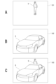
- 2A to 2C are diagrams illustrating a captured image, a CG image, and a composite image.
- FIG. 1 is a diagram showing a configuration of an imaging device.
- FIG. 1 is a block diagram showing an example of the configuration of an image processing device.
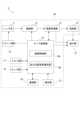
- FIG. 2 is a diagram showing a functional configuration of an image processing system.
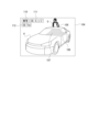
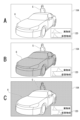
- FIG. 13 is a diagram illustrating an assist display.
- FIG. 13 is a diagram showing an example of a composite image for monitoring in which real object peaking display, virtual object peaking display, and virtual object texture display are performed.
- 10 is a flowchart showing a flow of a process of an assist display.
- FIG. 13A to 13C are diagrams showing modified examples of the assist display in the first embodiment.
- 13A to 13C are diagrams showing modified examples of the assist display in the first embodiment.
- 13A to 13C are diagrams showing modified examples of the assist display in the first embodiment.
- FIG. 13 is a diagram showing the overall configuration of an imaging system according to a second embodiment.
- 3A to 3C are diagrams illustrating a background image, a captured image, and a CG image.
- FIG. 13 is a diagram illustrating a composite image.
- FIG. 2 is a diagram showing a functional configuration of the imaging system.
- 11A and 11B are diagrams illustrating an example of assist display on a virtual object.
- 13A and 13B are diagrams illustrating a modified example in which an assist display is performed on a virtual object.
- imaging includes not only imaging that involves recording of image data, but also imaging for displaying an image on a display unit without recording of image data, such as a so-called through image or live view image.
- Image refers to a moving image.
- image does not only refer to a state in which it is displayed on a display unit, but may also refer to image data that is not displayed on a display unit.
- real object refers not only to the target (subject) imaged by an imaging device, but also to the subject image captured in the image.
- virtual object refers not only to a virtual object generated by 3D CG processing, but also to a virtual object that appears in a CG image generated by rendering.
- FIG. 1 is a diagram showing an overview of an image processing system 1 according to a first embodiment of the present invention.
- Fig. 2 is a diagram for explaining a captured image, a CG image, and a composite image.
- an image processing system 1 according to an embodiment includes an imaging device 2 and an image processing device 3.
- the imaging device 2 captures an image of a real object 5 (here, a person) as a subject in response to the operation of the cameraman 4, thereby generating a captured image (moving image) 101 as shown in FIG. 2A.
- a real object 5 here, a person
- the imaging device 2 captures an image of a real object 5 (here, a person) as a subject in response to the operation of the cameraman 4, thereby generating a captured image (moving image) 101 as shown in FIG. 2A.
- the image processing device 3 is, for example, a workstation.
- the image processing device 3 may be located at the imaging site, or may be located at a location different from the imaging site.
- the image processing device 3 is connected to the imaging device 2 wirelessly or via a wire, and receives the captured image 101 from the imaging device 2 and transmits the composite image 103 to the imaging device 2.
- the image processing device 3 generates a CG image 102 in which a virtual object 6 (here, a car) appears as shown in FIG. 2B. Then, the image processing device 3 composites the captured image 101 with the CG image 102 (virtual object 6) to generate a composite image 103 as shown in Fig. 2C. Note that the composite image 103 may also include a frame in which the CG image 102 is not composited. After that, the image processing device 3 transmits the generated composite image 103 to, for example, one or both of the imaging device 2 and the monitor 7.
- the imaging device 2 When the imaging device 2 receives the composite image 103 from the image processing device 3 , the imaging device 2 displays the received composite image 103 on the display unit 15 . Upon receiving the composite image 103 from the image processing device 3 , the monitor 7 displays the received composite image 103 .
- the cameraman 4 it is possible for the cameraman 4 to view the composite image 103 as a moving image in almost real time while the imaging device 2 is capturing images, i.e., an image in which the virtual object 6 is superimposed on the captured image 101.
- FIG. 3 is a diagram showing the configuration of the imaging device 2.
- the imaging device 2 includes a lens system 11, an imaging unit 12, an image processing unit 13, a recording unit 14, a display unit 15, a camera control unit 16, a memory unit 17, a driver unit 18, a sensor unit 19, a communication unit 20, and an operation unit 21.
- all the units constituting the imaging device 2 except for the display unit 15 will be collectively referred to as a main body unit 2A.
- the lens system 11 includes lenses such as a zoom lens and a focus lens, an aperture mechanism, etc.
- the lens system 11 also includes a motor for operating these lenses and the aperture mechanism.
- the lens system 11 collects light (incident light) from the real object 5 onto the imaging unit 12.
- the lens system 11 may be provided integrally with the imaging device 2 , or may be configured as an interchangeable lens separate from the imaging device 2 .
- the imaging unit 12 includes an image sensor (imaging element), such as a complementary metal oxide semiconductor (CMOS) type or a charge coupled device (CCD) type.
- CMOS complementary metal oxide semiconductor
- CCD charge coupled device
- the imaging unit 12 performs, for example, CDS (Correlated Double Sampling) processing, AGC (Automatic Gain Control) processing, etc., on the electric signal obtained by photoelectrically converting the light received by the image sensor, and further performs A/D (Analog/Digital) conversion processing. Then, the imaging unit 12 outputs the captured image signal as digital data to the image processing unit 13.
- CDS Correlated Double Sampling
- AGC Automatic Gain Control
- A/D Analog/Digital
- the image processing unit 13 is configured as an image processor, for example, a DSP (Digital Signal Processor).
- the image processing unit 13 performs various signal processing on the captured image signal from the imaging unit 12.
- the image processing unit 13 performs, for example, pre-processing, synchronization processing, YC generation processing, resolution conversion processing, file formation processing, etc.
- the captured image signal from the imaging unit 12 is subjected to a clamping process for clamping the R, G, and B black levels to a predetermined level, a correction process between the R, G, and B color channels, and the like.
- a color separation process is performed so that the image data for each pixel has all color components of R, G, and B.
- a demosaic process is performed as the color separation process.
- YC generation process a luminance (Y) signal and a color (C) signal are generated (separated) from R, G, and B image data.
- the resolution conversion process the image data that has been subjected to various signal processes is subjected to the resolution conversion process.
- the image data that has been subjected to the various processes described above is subjected to compression encoding for recording or communication, formatting, generation and addition of metadata, etc., to generate a file for recording or communication.
- an image file is generated in the MP4 format used for recording moving images and audio conforming to MPEG-4. It is also possible to generate an image file as raw (RAW) image data.
- the recording unit 14 is a memory card (such as a portable flash memory) that is a recording medium that can be attached to and detached from the imaging device 2, or a flash memory or HDD (hard disk drive) that is built into the imaging device 2.
- the recording unit 14 records the image data output from the image processing unit 13.
- the display unit 15 executes various displays on the display screen based on instructions from the camera control unit 16 .
- the display unit 15 displays a reproduced image of the image data read out from the recording unit 14 .
- the display unit 15 displays the composite image 103 transmitted from the image processing device 3 in response to an instruction from the camera control unit 16.
- the composite image 103 during composition confirmation, video recording, etc. is displayed on the display unit 15 as a so-called through image.
- the display unit 15 may display various operation menus, icons, messages, etc., that is, a GUI (Graphical User Interface), on the screen based on instructions from the camera control unit 16 .
- GUI Graphic User Interface
- the camera control unit 16 is composed of a microcomputer (arithmetic processing device) equipped with a CPU (Central Processing Unit).
- the memory unit 17 stores information and the like used for processing by the camera control unit 16.
- the memory unit 17 collectively refers to, for example, a read only memory (ROM), a random access memory (RAM), a flash memory, and the like.
- the memory unit 17 may be a memory area built into the microcomputer chip serving as the camera control unit 16, or may be configured by a separate memory chip.
- the camera control unit 16 executes a program stored in the ROM, flash memory, or the like of the memory unit 17 to control the entire imaging device 2.
- the camera control unit 16 includes functional units serving as an imaging control unit 16a and a self-position and orientation estimation unit 16b.
- the imaging control unit 16a controls the operation of each part required for imaging, such as controlling the shutter speed of the imaging unit 12, instructing various signal processing in the image processing unit 13, imaging operations and recording operations in response to operations by the cameraman 4, playback operations of recorded image data, and control operations of the lens system 11 such as zoom, focus, and aperture adjustment. Furthermore, the imaging control unit 16a calculates the angle of view, aperture value, lens distortion, and focal distance of the imaging device 2 as lens information based on the specifications of the lenses and aperture mechanism constituting the lens system 11, the movement of the focus lens and zoom lens, the opening and closing of the aperture mechanism, etc. Note that the method of calculating this lens information can be a known method, and therefore the description thereof will be omitted.
- the self-position and orientation estimation unit 16 b estimates the position and orientation of the imaging device 2 based on detection information from the sensor unit 19 (in this example, three-axis acceleration information and angular velocity information) and an image captured by the imaging unit 12 .
- position and orientation estimation techniques include SLAM (Simultaneous Localization and Mapping), VIO (Visual Inertial Odometry), etc.
- VIO assumes that the position and orientation are estimated by a technique such as INS (Inertial Navigation System) using the output of an IMU (sensor unit 19) that has a higher output rate than an image sensor (imaging unit 12). It is also possible to adopt a method such as Visual Odometry (VO) as a method that does not use the detection information of the IMU.
- INS Intelligent Localization and Mapping
- VIO Visual Odometry
- the RAM in the memory unit 17 is used as a working area for various data processing by the CPU of the camera control unit 16, and is used for temporarily storing data, programs, and the like.
- the ROM and flash memory (non-volatile memory) in the memory unit 17 are used to store an OS (Operating System) for the CPU to control each unit, application programs for various operations, firmware, various setting information, etc.
- the various types of setting information include exposure settings, shutter speed settings, and mode settings as setting information related to imaging operations, white balance settings, color settings, and settings related to image effects as setting information related to image processing, and custom key settings and display settings as setting information related to operability.
- the driver unit 18 includes, for example, a motor driver for a zoom lens drive motor, a motor driver for a focus lens drive motor, a motor driver for a diaphragm mechanism motor, and the like. These motor drivers apply drive currents to the corresponding drivers in response to instructions from the camera control unit 16, thereby moving the focus lens and zoom lens, opening and closing the aperture blades of the aperture mechanism, and so on.
- the sensor unit 19 collectively represents various sensors mounted on the imaging device 2 .
- An example of the sensor unit 19 is an inertial measurement unit (IMU).
- the IMU has a three-axis acceleration sensor and an angular velocity sensor, and outputs three-axis acceleration information and angular velocity information.
- the communication unit 20 is capable of performing wired or wireless inter-device communication, and network communication, which is communication with an external device via a specific communication network such as the Internet.
- the communication unit 20 transmits the captured image 101 to the image processing device 3, for example, and receives the composite image 103.
- the operation unit 21 collectively represents an input device for the user (cameraman 4) to input various operations. Specifically, the operation unit 21 is various operators (keys, dials, touch panel) or a touch panel. When the operation unit 21 detects a user operation, a signal corresponding to the input operation is sent to the camera control unit 16 .
- FIG. 4 is a block diagram showing an example of the configuration of the image processing device 3.
- the image processing device 3 includes a CPU 31.
- the CPU 31 executes various processes according to a program stored in a ROM 32 or a program loaded from a storage unit 39 to a RAM 33.
- the RAM 33 also stores data necessary for the CPU 31 to execute various processes as appropriate.
- the CPU 31 , the ROM 32 and the RAM 33 are connected to each other via a bus 43 .
- a GPU 34 is connected to the bus 43 .
- the GPU 34 performs 3DCG processing mainly in real time in accordance with drawing commands from the CPU 31 .
- an input/output interface (I/F) 35 is connected to the bus 43 .
- An input unit 36 including an operator or an operating device is connected to the input/output interface 35.
- the input unit 36 may be various operators or operating devices such as a keyboard, a mouse, a key, a dial, a touch panel, a touch pad, or a remote controller.
- An operation is detected by the input unit 36 , and a signal corresponding to the detected operation is interpreted by the CPU 31 .
- the input/output interface 35 is also connected, either integrally or separately, to a display unit 37 such as an LCD (Liquid Crystal Display) or an organic EL (Electro-Luminescence) panel, and an audio output unit 38 such as a speaker.
- the display unit 37 is used to display various types of information, and is configured, for example, by a display device provided in the housing of the image processing device 3, or a separate display device connected to the image processing device 3.
- the display unit 37 may be the monitor 7.
- the display unit 37 displays images for various types of image processing, videos to be processed, etc., on the display screen based on instructions from the CPU 31.
- the display unit 37 also displays various operation menus, icons, messages, etc., i.e., a GUI (Graphical User Interface), based on instructions from the CPU 31.
- GUI Graphic User Interface
- the input/output interface 35 is connected to a memory unit 39 and a communication unit 40, which are composed of a solid state drive (SSD) or hard disk drive (HDD).
- SSD solid state drive
- HDD hard disk drive
- the communication unit 40 is capable of performing network communication, which is wired or wireless device-to-device communication and communication with an external device via a specific communication network such as the Internet.
- network communication which is wired or wireless device-to-device communication and communication with an external device via a specific communication network such as the Internet.
- it is configured to be capable of performing data communication with the communication unit 20 of the imaging device 2.
- a drive 41 is connected to the input/output interface 35 as necessary, and a removable recording medium 42 such as a magnetic disk, optical disk, magneto-optical disk, or semiconductor memory is appropriately attached.
- the drive 41 can read data files such as programs used in each process from the removable recording medium 42.
- the read data files are stored in the storage unit 39, and images and sounds contained in the data files are output on the display unit 37 and the audio output unit 38.
- the computer programs and the like read from the removable recording medium 42 are installed in the storage unit 39 as necessary.
- FIG. 5 is a diagram showing a functional configuration of the image processing system 1.
- the CPU 31 and GPU 34 of the image processing device 3 function as a CG generating unit 51 and a first composition unit 52.
- these functional units may be configured to function only by one of the CPU 31 and the GPU 34.
- one functional unit may be configured to function by both the CPU 31 and the GPU 34.
- a captured image 101 captured by the imaging unit 12 of the imaging device 2 (more precisely, a captured image 101 that has been subjected to image processing by the image processing unit 13) is transmitted to the image processing device 3 via the communication unit 20.
- camera information 109 when the captured image 101 is captured is transmitted to the image processing device 3 via the communication unit 20.
- the camera information 109 may be metadata added to the captured image 101, or may be information independent of the captured image 101.
- the camera information 109 includes the position, orientation, angle of view, aperture value, lens distortion, focal distance, etc. of the imaging device 2. This information is transmitted for each frame constituting the captured image 101, for example.
- the position and orientation of the imaging device 2 are estimated for each frame by the self-position and orientation estimation unit 16b.
- the angle of view, aperture value, lens distortion, and focal distance of the imaging device 2 are calculated as lens information by the imaging control unit 16a as described above.
- the image processing device 3 When the image processing device 3 receives the captured image 101 and the camera information 109, it inputs the captured image 101 to the first synthesis unit 52 and inputs the camera information 109 to the CG generation unit 51.
- the CG generation unit 51 includes a vertex shader unit 51a, a pixel shader unit 51b, a blur expression unit 51c, and a first image processing unit 51d.
- the CG generation unit 51 is not limited to this, and may have other configurations as long as it can generate a CG image 102 from a 3D model.
- the vertex shader unit 51a When the vertex shader unit 51a receives the camera information 109, it sets the angle of view, aperture value, lens distortion, and focal distance of the virtual camera that virtually captures images in the virtual space represented by the CG model, based on the angle of view, aperture value, lens distortion, and focal distance contained in the camera information 109.
- the settings of the lens system of the virtual camera are made to match the settings of the lens system 11 of the imaging device 2.
- the vertex shader unit 51a updates the position and orientation of the virtual camera based on the position and orientation of the imaging device 2 included in the camera information 109.
- the position (coordinate position) of the virtual object 6 is shown in a coordinate system based on a predetermined position in the virtual space.
- the coordinate system of the real space captured by the imaging device 2 is adjusted to match the coordinate system of the virtual space shown in the CG model. Therefore, by matching the position and orientation of the virtual camera with the position and orientation of the imaging device 2, the imaging range of the imaging device 2 and the imaging range of the virtual camera can be matched.
- the vertex shader unit 51a performs processing such as converting the shape of the virtual object 6 when viewed from the position and orientation of the virtual camera.
- the pixel shader unit 51b performs processing (shading) to determine the final color for a pixel.
- Shading processing includes texture mapping, lighting, and other processing.
- various other processing is performed on a fragment-by-fragment basis.
- the blur expression unit 51c calculates the focus position and depth of field of the imaging device 2 (virtual camera) based on the angle of view, aperture value, lens distortion, focusing distance, etc. of the imaging device 2 included in the camera information. Then, the blur expression unit 51c performs processing to express image blur in a part of the virtual object 6 outside the depth of field. As a result, a CG image 102 is generated in which the virtual object 6 is depicted with a blurred expression applied by the blur expression unit 51c. The generated CG image 102 is output to the first synthesis unit 52 and the first image processing unit 51d.
- the first synthesis unit 52 generates a composite image 103 in which a virtual object 6 is superimposed on the captured image 101 by synthesizing the captured image 101 transmitted from the imaging device 2 with the CG image 102 generated by the CG generation unit 51.
- a virtual object 6 exists in front of the real object 5
- the virtual object 6 may exist behind the real object 5 .
- the captured image 101 contains information regarding the distance to the real object 5 for each pixel
- the CG image 102 contains information regarding the distance to the virtual object 6 for each pixel
- a composite image 103 is generated so that the pixels in the foreground are given priority.
- the cameraman 4 may display a composite image 103 on the display unit 15 or monitor 7 and perform a focus operation on the imaging device 2 while checking the composite image 103.
- the image processing system 1 therefore displays a monitor composite image 104 on the display unit 15 and monitor 7, which is the composite image 103 generated as described above and to which an assist display has been added.
- the first image processing unit 51d processes the virtual object 6 that has been subjected to the blurring expression by the blurring expression unit 51c in order to perform an assist display, and outputs a CG image 102 in which the virtual object 6 appears to the imaging device 2.
- the assist display is, for example, a peaking display or a texture display. The assist display will be described in detail later.
- the first image processing unit 51d does not process the CG image 102 input from the blur expression unit 51c. In such cases, the CG image 102 that has not been processed is output to the imaging device 2 as is.
- the camera control unit 16 of the imaging device 2 functions as a second image processing unit 53 and a second synthesis unit 54 in addition to the imaging control unit 16a and self-position and orientation estimation unit 16b described above.
- the second image processing unit 53 receives the captured image 101 from the image processing unit 13 and recognizes the real object 5 from the input captured image 101.
- the second image processing unit 53 then performs processing on the recognized real object 5 to provide an assist display, and outputs the captured image 101 after processing to the second synthesis unit 56.
- the assist display is, for example, a peaking display. The assist display will be described in detail later.
- the second image processing unit 53 does not perform processing on the captured image 101 input from the image processing unit 13. In such cases, the captured image 101 that has not been subjected to processing is output as is to the second synthesis unit 56.
- the second synthesis unit 54 synthesizes the captured image 101 input from the second image processing unit 53 and the CG image 102 input from the first image processing unit 51d to generate a composite image for monitoring 104.
- the generated composite image for monitoring 104 is output to the display unit 15 and the monitor 7.
- the display unit 15 of the imaging device 2 and the monitor 7 display the composite image 104 for monitoring.
- the assist display is a display for assisting imaging, and includes a peaking display and a texture display.
- the peaking display is a display in which an edge portion of a subject in an image that is in focus is highlighted.
- the peaking display can be performed for both the real object 5 and the virtual object 6 in the composite image 103. In other words, the peaking display can be performed for both the captured image 101 and the CG image 102.
- the second image processing unit 53 detects edges of the real object 5 in the captured image 101, and detects edge portions that are in focus among the detected edges.
- the in-focus edge portions may be detected by calculating high-frequency components in the captured image 101, or may be detected based on the focus position and depth of field of the imaging device 2 and the distance to the real object 5 calculated by SLAM or the like.
- the second image processing unit 53 detects an edge portion in focus, it generates a captured image 101 in which the edge portion is highlighted as an actual object peaking display 105, as shown in FIG. 6A. Possible methods for highlighting include displaying the edge portions with lines of a predetermined color, or increasing the brightness of the edge portions.
- the second synthesis unit 54 displays a guide 110 indicating that the real object peaking display 105 is being performed on the synthetic image for monitor 104.
- the guide 110 has, for example, the description "real image”. This allows the cameraman 4 to easily confirm which part of the real object 5 is in focus.
- the first image processing unit 51d When performing peaking display on the CG image 102 (virtual object 6), the first image processing unit 51d detects edges of the virtual object 6 in the CG image 102, and detects edge portions that are in focus among the detected edges.
- the edge portions that are in focus may be detected by calculating high-frequency components in the CG image 102, or may be detected based on the focus position and depth of field of the imaging device 2 and the distance from the imaging device 2 (virtual camera) to the virtual object 6.
- the first image processing unit 51d detects an edge portion in focus, it generates a CG image 102 in which the edge portion is highlighted as a virtual object peaking display 106, as shown in FIG. 6B.
- Possible methods for highlighting include displaying the edge portions with lines of a predetermined color, or increasing the brightness of the edge portions.
- the second synthesis unit 54 displays a guide 111 indicating that the virtual object peaking display 106 is being performed on the synthetic image for monitor 104.
- the guide 111 has, for example, a description "CG: Edge” written on it. This allows the cameraman 4 to easily confirm which part of the virtual object 6 is in focus.
- Texture display refers to highlighting a texture portion that is in focus among the surfaces that constitute a subject in an image. Texture display can be performed on the virtual object 6 in the composite image 103. In other words, texture display can be performed on the CG image 102.
- the first image processing unit 51d detects a texture portion in focus among the texture of the virtual object 6 in the CG image 102.
- the first image processing unit 51d detects a focused texture portion, it generates a CG image 102 in which the texture portion is highlighted as a virtual object texture display 107, as shown in FIG. 6C.
- a possible method of highlighting is to display the textured portion in a predetermined pattern (for example, a zebra pattern, a specific color, or hatching).
- a predetermined pattern for example, a zebra pattern, a specific color, or hatching.
- the second synthesis unit 54 displays a guide 112 indicating that the virtual object texture display 107 is being performed on the synthetic image for monitor 104.
- the guide 112 has, for example, "CG:Tex" written on it. This allows the cameraman 4 to easily confirm which part of the virtual object 6 is in focus.
- FIG. 7 is a diagram showing an example of a composite image 104 for monitoring in which the real object peaking display 105, the virtual object peaking display 106, and the virtual object texture display 107 have been performed.
- the above-mentioned real object peaking display 105, virtual object peaking display 106 and virtual object texture display 107 can be performed simultaneously.
- the second composition unit 54 composes the captured image 101 on which the real object peaking display 105 has been performed, and the CG image 102 on which the virtual object peaking display 106 and the virtual object texture display 107 have been performed.
- a composite image for monitoring 104 on which the real object peaking display 105, the virtual object peaking display 106, and the virtual object texture display 107 have been performed is generated.
- the generated composite image for monitoring 104 is then displayed on the display unit 15 and the monitor 7. In this composite monitor image 104, guides 110, 111, and 112 are also displayed.
- the first image processing unit 51d and the second image processing unit 53 make the color or thickness (width) of the lines different from each other, as shown in FIG. 7.
- the display modes of the real object peaking display 105 and the virtual object peaking display 106 are made different. This allows the cameraman 4 to easily understand whether the peaking display is for the real object 5 or the virtual object 6.
- the first image processing unit 51d and the second image processing unit 53 may alternately switch between the real object peaking display 105 and the virtual object peaking display 106 and the virtual object texture display 107. Furthermore, the first image processing unit 51d and the second image processing unit 53 may associate the real object peaking display 105 and the virtual object peaking display 106 and the virtual object texture display 107 with different operations of the operation unit 21.
- the first image processing unit 51d and the second image processing unit 53 may alternately switch between the real object peaking display 105, the virtual object peaking display 106 and the virtual object texture display 107, and the real object peaking display 105, the virtual object peaking display 106 and the virtual object texture display 107.
- the real object peaking display 105, the virtual object peaking display 106 and the virtual object texture display 107, and the real object peaking display 105, the virtual object peaking display 106 and the virtual object texture display 107 may be displayed in different display modes.
- the second image processing unit 53 detects the edges of the real object 5 from the captured image 101 using a predetermined threshold value for determining edges, and detects the edge portions of the detected edges that are in focus. Then, the second image processing unit 53 divides the captured image 101 into small grids of multiple pixel units, and calculates the area in which the real object peaking display 105 is performed by counting the number of small grids that contain at least one pixel of an edge portion that is in focus.
- the second image processing section 53 determines that the area in which the real object peaking display 105 is performed is large, and changes the threshold value to a larger value.
- the second image processing unit 53 detects the edges of the real object 5 from the captured image 101 using the changed threshold value, and detects edge portions that are in focus among the detected edges. Then, the second image processing unit 53 performs real object peaking display 105 on the detected edge portions. In this way, when the area where the real object peaking display 105 is performed is large, by reducing the area where the real object peaking display 105 is performed, it is possible to make it easier for the cameraman 4 to see which parts are in focus.
- the first image processing unit 51d changes the threshold value in the same manner as the second image processing unit 53, thereby making it easier for the photographer 4 to see which parts of the CG image 102 are in focus.
- the threshold value used when the second image processing unit 53 detects edges from the captured image 101 be different from the threshold value used when the CG generation unit 51 detects edges from the CG image 102 .
- the threshold value used when the CG generation unit 51 detects edges from the CG image 102 is set to a value smaller than the threshold value used when the second image processing unit 53 detects edges from the captured image 101 . This makes it possible to prevent the area of the real object peaking display 105 from becoming too large and the area of the virtual object peaking display 106 from becoming too small.
- the blurring effect section 51c does not perform blurring effect on the virtual object 6, the virtual object peaking display 106 and the virtual object texture display 107 may not be performed (assist display for the virtual object 6 may not be performed).
- the virtual object 6 is not blurred, the virtual object 6 is not expected to be focused on, so by not displaying the assist display for the virtual object 6, it is possible to reduce confusion of the cameraman 4.
- assisted display may not be performed for the virtual object 6.
- the virtual object 6, which is a non-assisted virtual object is given in advance as attribute information in the CG model that it is a non-assisted virtual object.
- the first image processing unit 51d may perform a fast Fourier transform on the virtual object 6, and determine that it is a non-assisted virtual object if it contains high-frequency components. The first image processing unit 51d does not perform assist display for the virtual object 6, which is a non-assist virtual object.
- the first image processing unit 51d may not perform assist display for the virtual objects 6. If assist display is performed when all virtual objects 6 included in the CG model are present within the depth of field of the imaging device 2, assist display will be performed on all virtual objects 6, which will make the monitor composite image 104 harder to see. Therefore, by not providing an assist display for the virtual objects 6 when all the virtual objects 6 included in the CG model are present within the depth of field of the imaging device 2, the composite image for monitoring 104 can be made easier to view. However, a guide indicating that all the virtual objects 6 included in the CG model are present within the depth of field of the imaging device 2 may be displayed.
- the colors of the real object peaking display 105, the virtual object peaking display 106, and the virtual object texture display 107 may be changed according to the surrounding colors. For example, when a color predetermined as the color of the virtual object peaking display 106 is close to the color of the surroundings of the virtual object peaking display 106 , the first image processing unit 51 d inverts the color of the virtual object peaking display 106 . This can reduce the difficulty in seeing the assist display.
- first image processing unit 51 d may perform virtual object texture display 107 instead of virtual object peaking display 106.
- first image processing unit 51 d may perform virtual object peaking display 106 instead of virtual object texture display 107.
- Fig. 8 is a flowchart showing the flow of the assist display process. Note that Fig. 8 shows the processes performed in parallel by the first image processing unit 51d and the second image processing unit 53 together.
- step S1 the first image processing unit 51d and the second image processing unit 53 determine whether the depth of field calculated based on the camera information is within a predetermined value. Here, they determine whether the depth of field is shallow and blurring occurs in the real object 5 or virtual object 6.
- step S1 If the depth of field is not within the predetermined value (Yes in step S1), the first image processing unit 51d and the second image processing unit 53 do not display the assist in step S2.
- step S3 the first image processing unit 51d and the second image processing unit 53 determine whether the virtual object 6 is blurred.
- step S4 the first image processing unit 51d does not perform assist display (virtual object peaking display 106, virtual object texture display 107) for the virtual object 6. Also, in step S4 the second image processing unit 53 performs assist display (real object peaking display 105) for the real object 5.
- step S5 the first image processing unit 51d and the second image processing unit 53 determine whether the virtual object 6 is a non-assisted virtual object.
- step S6 the first image processing unit 51d performs a virtual object peaking display 106 for the virtual object 6, and does not perform a virtual object texture display 107. Also, in step S6, the second image processing unit 53 performs an assisted display (real object peaking display 105) for the real object 5.
- step S7 the first image processing unit 51d performs assist display (virtual object peaking display 106, virtual object texture display 107) for the virtual object 6. Also in step S7 the second image processing unit 53 performs assist display (real object peaking display 105) for the real object 5.
- the first embodiment is not limited to the specific example described above, and various modified configurations may be adopted.
- the image capture device 2 performs assist display for the real object 5
- the image processing device 3 performs assist display for the virtual object 6.
- assist display for both the real object 5 and the virtual object 6 may be performed in either the image capture device 2 or the image processing device 3.
- the assist displays are the real object peaking display 105, the virtual object peaking display 106, and the virtual object texture display 107.
- the assist displays are not limited to these, and may be other displays that assist the cameraman 4 in the imaging operation.
- the second image processing unit 53 may assist in displaying the brightness (Exposure) distribution 120 of the real object 5 and the virtual object 6.
- Fig. 9A illustrates a case where the brightness of the real object 5 and the virtual object 6 is substantially the same
- Fig. 9B illustrates a case where the brightness of the virtual object 6 is low
- Fig. 9C illustrates a case where the brightness of the real object 5 is low.
- the second image processing unit 53 may assist in displaying color histogram distributions 121 of the real object 5 and the virtual object 6.
- Fig. 10A illustrates a case where the brightness of the real object 5 and the virtual object 6 is substantially the same
- Fig. 10B illustrates a case where the real object 5 is whitish
- Fig. 10C illustrates a case where the virtual object 6 is whitish.
- the second image processing unit 53 may display one or both of the real object 5 and the virtual object 6 in false color as an assist display.
- Fig. 11A shows a case where the real object 5 and the virtual object 6 are not displayed in false color
- Fig. 11B shows a case where only the real object 5 is displayed in false color
- Fig. 10C shows a case where only the virtual object 6 is displayed in false color
- Fig. 11D shows a case where the real objects 5 and 6 are displayed in false color.
- Second embodiment in a studio equipped with a large display device, a background image is displayed on the display device and performers perform in front of it, thereby providing assist display in a so-called virtual production in which the performers and the background can be filmed.
- FIG. 12 is a diagram showing the overall configuration of an image capture system 500 according to the second embodiment.
- the image capture system 500 is provided with a performance area 501 in which a performer 510, which is an example of a real object 5, performs a performance or other performance.
- a large display device is disposed at least on the rear surface, and further on the left and right sides and top surface of this performance area 501.
- the type of device of the display device is not limited, but the figure shows an example in which an LED wall 505 is used as an example of a large display device.
- a single LED wall 505 is formed by arranging multiple LED panels 506 connected vertically and horizontally to form a large panel.
- the size of the LED wall 505 is not particularly limited, but it should be a size that is necessary or large enough to display the background when filming the performer 510.
- the required number of lights 580 are placed in required positions, such as above or to the sides of the performance area 501, to illuminate the performance area 501.
- a capture device 2 for capturing images of movies and other video content is placed near the performance area 501.
- the imaging device 2 captures the performer 510 in the performance area 501 and the image displayed on the LED wall 505 together. For example, by displaying a landscape as background image vB on the LED wall 505, it is possible to capture a moving image similar to that in which the performer 510 is actually performing in the location of that landscape.
- a monitor 7 is placed near the performance area 501.
- the monitor 7 displays the captured images 101 captured by the imaging device 2 in real time. This allows the director, staff, and cameraman 4 who are producing the video content to check the captured images 101.
- the shooting system 500 which shoots the performance of the performer 510 in a shooting studio with an LED wall 505 as a backdrop, has various advantages over green screen shooting.
- post-production is more efficient than when shooting against a green screen. This is because in some cases so-called chromakey compositing is not necessary, and in other cases color correction and reflection compositing are not necessary. Even if chromakey compositing is required during shooting, there is no need to add a background screen, which also contributes to efficiency.
- the green hue does not increase, so correction for this is not necessary. Also, by displaying the background image vB, reflections on actual objects such as glass are naturally captured and captured, so there is no need to synthesize the reflected image.
- the shooting system 500 also includes a rendering engine 520, an asset server 530, a sync generator 540, an operation monitor 550, a camera tracker 560, an LED processor 570, a lighting controller 581, and a display controller 590.
- the LED processor 570 is provided for each LED panel 506 and drives the image display of the corresponding LED panel 506.
- the sync generator 540 generates a synchronization signal for synchronizing the frame timing of the image displayed by the LED panel 506 with the frame timing of the image captured by the imaging device 2, and supplies the synchronization signal to each LED processor 570 and the imaging device 2. However, this does not prevent the output from the sync generator 540 from being supplied to the rendering engine 520.
- the camera tracker 560 generates camera information by the imaging device 2 at each frame timing and supplies it to the rendering engine 520.
- the camera information may be generated by the imaging device 2.
- the camera tracker 560 detects, as one piece of camera information, the position of the LED wall 505 or position information of the imaging device 2 relative to a predetermined reference position, and the shooting direction of the imaging device 2, and supplies these to the rendering engine 520.
- a specific detection method by the camera tracker 560 is to randomly place reflectors on the ceiling and detect the position from the reflected light of infrared light irradiated from the imaging device 2.
- Another detection method is to estimate the self-position of the imaging device 2 by using gyro information mounted on the camera platform of the imaging device 2 or the main body of the imaging device 2, or by image recognition of the captured image 101 of the imaging device 2.
- the imaging device 2 may supply the rendering engine 520 with camera information such as the angle of view, focal length, F-number, shutter speed, and lens information.
- the rendering engine 520 performs processing to generate the background image vB to be displayed on the LED wall 505. To this end, the rendering engine 520 reads out necessary 3D background data from the asset server 530. The rendering engine 520 then generates an image of the outer frustum used in the background image vB by rendering the 3D background data as viewed from pre-specified spatial coordinates. In addition, the rendering engine 520 uses camera information supplied from the camera tracker 560 and the imaging device 2 to identify the viewpoint position relative to the 3D background data, and renders the shooting area image vBC (inner frustum) for each frame.
- vBC inner frustum
- the rendering engine 520 further synthesizes the previously generated outer frustum with the shooting area image vBC rendered for each frame to generate a background image vB as one frame of image data. The rendering engine 520 then transmits the generated one frame of image data to the display controller 590.
- the display controller 590 generates a divided video signal nD by dividing one frame of video data into video portions to be displayed on each LED panel 506, and transmits the divided video signal nD to each LED panel 506.
- the display controller 590 may perform calibration according to individual differences in color development and the like between display sections/manufacturing errors and the like. Note that these processes may be performed by the rendering engine 520 without providing the display controller 590. In other words, the rendering engine 520 may generate the divided video signal nD, perform calibration, and transmit the divided video signal nD to each LED panel 506.
- Each LED processor 570 drives the LED panel 506 based on the divided video signal nD received, causing the entire background image vB to be displayed on the LED wall 505.
- the background image vB includes the shooting area image vBC that is rendered according to the position of the imaging device 2 at that time, etc.
- the imaging device 2 can thus capture the performance of the performer 510, including the background image vB displayed on the LED wall 505.
- the captured image 101 obtained by the imaging device 2 is recorded on a recording medium inside the imaging device 2 or in an external recording device (not shown).
- the operation monitor 550 displays an operation image vOP for controlling the rendering engine 520.
- the engineer 511 can perform the necessary settings and operations related to the rendering of the background image vB while viewing the operation image vOP.
- the lighting controller 581 controls the light emission intensity, light emission color, irradiation direction, etc. of the light 580.
- the lighting controller 581 may control the light 580 asynchronously with the rendering engine 520, for example, or may control the light 580 synchronously with the shooting information and rendering processing. Therefore, the lighting controller 581 may control the light emission according to instructions from the rendering engine 520 or a master controller (not shown).
- the imaging system 500 is also provided with an image processing device 3 (indicated as a Computer in the figure).
- the image processing device 3 generates a CG image 102 in which a virtual object 6 based on a 3D model appears.
- the imaging device 2 then generates a composite image 103 by combining the captured image 101 and the CG image 102, and displays the composite image 103 on the display unit 15 and the monitor 7.
- Fig. 13 is a diagram for explaining a background image, a captured image, and a CG image
- Fig. 14 is a diagram for explaining a composite image.
- a background image vB in which a virtual object 201 appears is projected onto an LED wall 505.
- the image processing device 3 generates a CG image 102 in which a virtual object 6 as shown in Fig. 13C appears.
- the captured image 101 shown in Fig. 13B and the CG image 102 shown in Fig. 13C are composited to generate a composite image 103 shown in Fig. 14.
- assist display is performed for the virtual object 201 based on the background image vB appearing in the captured image 101.
- the imaging device 2 is provided with a main body section 2A, a display section 15, a second image processing section 53, and a second synthesis section 54.
- the image processing device 3 is provided with a CG generation section 51 and a first synthesis section 52.
- Camera information is input to a rendering engine 520 in the imaging system 500.
- a synchronization signal output from a sync generator 540 is input to the imaging device 2, image processing device 3, and cameraman 4 for synchronization.
- FIG. 16 is a diagram illustrating an example of assist display on a virtual object 201.
- the rendering engine 520 detects a texture portion that is in focus among the texture of the virtual object 201 in the background image vB. The focus is calculated based on camera information.
- the rendering engine 520 detects a texture portion that is in focus, it generates a background image vB in which the texture portion is highlighted as a virtual object texture representation 210, as shown in FIG. 16A.
- a possible method of highlighting is to display the textured portion in a predetermined pattern (for example, a zebra pattern, a specific color, or hatching).
- the generated background image vB is displayed on the LED wall 505 via the display controller 590 and the LED processor 570. Then, the background image vB with the virtual object texture display 210 is captured by the imaging device 2, and finally, as shown in FIG. 16B, the composite image for monitor 104 with the virtual object texture display 210 applied to the virtual object 201 is displayed on the display unit 15 and the monitor 7.
- the rendering engine 520 if the frame rate of the imaging device 2 and the LED wall 505 can be doubled, the rendering engine 520 generates, for example, a background image vB in which the virtual object texture display 210 is not performed for even-numbered frames, and generates a background image vB in which the virtual object texture display 210 is performed for odd-numbered frames. In other words, the rendering engine 520 switches between the presence and absence of the virtual object texture display 210 alternately between frames.
- the imaging device 2 When the background image vB generated in this manner is displayed on the LED wall 505 and captured by the imaging device 2, the imaging device 2 divides it into a captured image 101 of only even frames and a captured image 101 of only odd frames. The imaging device 2 then records the captured image 101 of only even frames as the main video. Meanwhile, the captured image 101 of only odd frames is composited with a CG image 102 to generate a composite image 104 for monitoring.
- the second embodiment is not limited to the specific example described above, and various modified configurations may be adopted.
- a virtual object texture display 210 is displayed on the background image vB.
- a virtual object texture display 210 may be performed on the CG image 102 .
- the CG generation unit 51 acquires a 3D model (3D background data) from the asset server 530, and generates a background image vB based on camera information.
- the CG generation unit 51 also detects a focused texture portion of the texture of the virtual object 201 in the background image vB.
- the CG generation unit 51 detects the focused texture portion, it generates a CG image 102 in which the virtual object texture display 210 is highlighted at a position corresponding to the focused texture portion, as shown in Fig. 17B. Note that the background image vB displayed on the LED wall 505 does not include the virtual object texture display 210, as shown in Fig. 17A.
- a CG image 102 as shown in FIG. 17B is composited with an imaged image 101 obtained by capturing the background video vB by the imaging device 2, and finally, as shown in FIG. 17C, a composite image for monitor 104 in which a virtual object texture display 210 is applied to a virtual object 201 is displayed on the display unit 15 and the monitor 7.
- the image processing method displays a composite image (composite image for monitor 104) in which a virtual object 6 is superimposed on an imaged image 101 obtained by the imaging device 2 on a display unit (display unit 15, monitor 7), and provides an assist display for assisting in imaging of the virtual object 6 in the composite image 103.
- This allows the cameraman 4 to easily confirm the part that is in focus by the assist displays (virtual object peaking display 106, virtual object texture display 107) when, for example, focusing on the virtual object 6. Therefore, the convenience of the composite image for the user during image capture can be improved.
- a texture display (virtual object texture display 107) is performed on the portion of the virtual object 6 on which the imaging device 2 is focused. This allows the cameraman 4 to easily confirm which part of the virtual object 6 is in focus.
- peaking display real object peaking display 105, virtual object peaking display 106
- the peaking display is performed in different display modes for the virtual object 6 and the real object 5. This makes it easy to know whether the peaking display is being performed on the virtual object 6 or the real object 5.
- the assist display is not performed for the virtual object 6.
- the virtual object 6 is not expected to be focused on, so by not displaying the assist display for the virtual object 6, it is possible to reduce confusion of the cameraman 4.
- assist display is not performed for the virtual object 6. If assist display is applied to all virtual objects 6, the composite image for monitor 104 becomes difficult to see. Therefore, by not applying assist display to the virtual objects 6, the composite image for monitor 104 can be made easier to see.
- the sensitivity of the peaking display is reduced and the peaking display is performed.
- the sensitivity is lowered to reduce the area where the peaking display is performed, thereby making it easier for the cameraman 4 to see which part is in focus.
- a brightness distribution 120 of the real object 5 and the virtual object 6 is displayed.
- the cameraman 4 can easily adjust the aperture. Also, the brightness of the virtual object 6 can be reduced.
- a color histogram distribution 121 of the real object 5 and the virtual object 6 is displayed.
- the cameraman 4 can easily adjust the white balance. Also, the cameraman 4 can adjust the white balance of the virtual object 6.
- a real object 5 and a virtual object 6 are displayed in false color.
- the cameraman 4 can easily adjust the brightness.
- the brightness of the virtual object 6 can be adjusted.
- the display device (LED wall 505) on which the virtual object 201 is displayed is imaged by the imaging device 2, so that the virtual object 201 appears in the captured image 101, and the assist display is performed by the image (background image vB) displayed on the display device.
- the background image vB displayed on the LED wall 505 can perform assist display.
- the assist display is performed every other frame among consecutive frames displayed on the display device (LED wall 505). This makes it possible to generate the main video and a monitor composite image 104 for confirmation with a single image capture.
- the virtual object 201 is displayed on a display device (LED wall 505), and the assist display is performed on an image (CG image 102) different from the display device.
- the assist display is not displayed on the LED wall 505, and it is possible to prevent the assist display from being reflected in the captured image 101 obtained by capturing an image with the imaging device 2.
- the image processing device 3 has a control unit (CPU 31) that displays a composite image 103 (104) in which a virtual object 6 is superimposed on an imaged image 101 obtained by the imaging device 2 on a display unit (display unit 15, monitor 7), and performs assist display (virtual object peaking display 106, virtual object texture display 107) to assist in imaging of the virtual object 6 in the composite image 103.
- the image processing system 1 includes an imaging device 2 and an image processing device 3.
- the imaging device 2 includes an imaging unit 12 that obtains an imaged image 101 by imaging a real space.
- the image processing device 3 includes a control unit (CPU 31) that displays a composite image 103 (104) in which a virtual object 6 is superimposed on the imaged image 101 obtained by the imaging device 2 on a display unit (display unit 15, monitor 7) and performs assist display (virtual object peaking display 106, virtual object texture display 107) that is a display for assisting in imaging the virtual object 6 in the composite image 103.
- a control unit CPU 31
- the image processing device 3 includes a control unit (CPU 31) that displays a composite image 103 (104) in which a virtual object 6 is superimposed on the imaged image 101 obtained by the imaging device 2 on a display unit (display unit 15, monitor 7) and performs assist display (virtual object peaking display 106, virtual object texture display 107) that is a display for assisting in imaging the virtual object 6 in the composite image 103.
- the present technology can also be configured as follows.
- An image processing method comprising: displaying, on a display unit, a composite image in which a virtual object is superimposed on an image captured by an imaging device; and providing an assist display for assisting in capturing an image of the virtual object in the composite image.
- the display device on which the virtual object is displayed is imaged by the imaging device, so that the virtual object appears in the image;
- the virtual object is displayed on a display device;
- An image processing device comprising: a control unit that displays, on a display unit, a composite image in which a virtual object is superimposed on an image captured by an imaging device, and performs an assist display that is a display for assisting in capturing an image of the virtual object in the composite image.
- An image processing system including an imaging device and an image processing device, The imaging device includes an imaging unit that obtains an image by imaging a real space, The image processing system includes a control unit that displays, on a display unit, a composite image in which a virtual object is superimposed on a captured image obtained by the imaging device, and performs an assist display that is a display to assist in capturing an image of the virtual object in the composite image.
Landscapes
- Engineering & Computer Science (AREA)
- Multimedia (AREA)
- Signal Processing (AREA)
- Image Processing (AREA)
Abstract
本技術に係る画像処理方法は、撮像装置により得られる撮像画像に対して仮想物体が重畳された合成画像を表示部に表示し、合成画像内の仮想物体に対して撮像を補助するための表示であるアシスト表示を行う。
Description
本技術は、画像処理方法、画像処理装置及び画像処理システムに関するものであり、特には、撮像画像に仮想物体を重畳する技術に関するものである。
例えば特許文献1に開示されるように、カメラによって撮像されることで得られた撮像画像と、3DCG(Three Dimensional Computer Graphic)処理により生成されたCG画像とをリアルタイムで合成し、合成した合成画像(所謂AR画像)をカメラモニタに表示させるようになされたシステムが提案されている。
このシステムでは、合成画像をリアルタイムでカメラモニタに表示することができるので、カメラマンはリアルタイムで合成画像を確認することができるとともに、合成画像を見ながらカメラを操作することができる。
このシステムでは、合成画像をリアルタイムでカメラモニタに表示することができるので、カメラマンはリアルタイムで合成画像を確認することができるとともに、合成画像を見ながらカメラを操作することができる。
特許文献1に開示されている技術では、カメラマンが合成画像を確認しながらフォーカスを調整する場合に、合成画像を確認するだけではCG画像に写し出される仮想物体にフォーカスを合わせることが困難であった。そこで、撮像時にカメラマンに対する合成画像の利便性を向上させることが希求されている。
本技術は上記事情に鑑み為されたものであり、撮像時にユーザに対する合成画像の利便性を向上させることを目的とする。
本技術に係る画像処理方法は、撮像装置により得られる撮像画像に対して仮想物体が重畳された合成画像を表示部に表示し、前記合成画像内の前記仮想物体に対して撮像を補助するための表示であるアシスト表示を行う。
上記の画像処理方法によれば、例えば仮想物体にフォーカスを合わせる際にアシスト表示によりカメラマンに容易にフォーカスが合っている部分を確認させることが可能となる。
上記の画像処理方法によれば、例えば仮想物体にフォーカスを合わせる際にアシスト表示によりカメラマンに容易にフォーカスが合っている部分を確認させることが可能となる。
以下、添付図面を参照し、本技術に係るセンサ装置の実施形態を次の順序で説明する。
<1.第1の実施形態>
<2.第2の実施形態>
<3.実施形態のまとめ>
<4.本技術>
なお、本技術において「撮像」とは、画像データの記録を伴う撮像のみでなく、所謂スルー画やライブビュー画のように画像データの記録を伴わずに表示部に画像を表示させるための撮像を含むものである。
「画像」とは、動画像を示すものである。また、「画像」とは、表示部に表示されている状態を指すだけでなく、表示部に表示されていない状態の画像データについても「画像」と表記することがある。
「実物体」とは、撮像装置によって撮像される対象(被写体)を指すだけでなく、画像に写っている被写体像も含むものである。
「仮想物体」とは、3DCG処理により生成される仮想的な物体を指すだけでなく、レンダリングにより生成されるCG画像に写っている仮想的な物体も含むものである。
<1.第1の実施形態>
<2.第2の実施形態>
<3.実施形態のまとめ>
<4.本技術>
なお、本技術において「撮像」とは、画像データの記録を伴う撮像のみでなく、所謂スルー画やライブビュー画のように画像データの記録を伴わずに表示部に画像を表示させるための撮像を含むものである。
「画像」とは、動画像を示すものである。また、「画像」とは、表示部に表示されている状態を指すだけでなく、表示部に表示されていない状態の画像データについても「画像」と表記することがある。
「実物体」とは、撮像装置によって撮像される対象(被写体)を指すだけでなく、画像に写っている被写体像も含むものである。
「仮想物体」とは、3DCG処理により生成される仮想的な物体を指すだけでなく、レンダリングにより生成されるCG画像に写っている仮想的な物体も含むものである。
<1.第1の実施形態>
[1.1.画像処理システムの全体構成]
図1は、第1の実施形態としての画像処理システム1の概要を示した図である。図2は、撮像画像、CG画像及び合成画像を説明する図である。
図1に示すように、実施形態としての画像処理システム1は、撮像装置2及び画像処理装置3を備えて構成される。
[1.1.画像処理システムの全体構成]
図1は、第1の実施形態としての画像処理システム1の概要を示した図である。図2は、撮像画像、CG画像及び合成画像を説明する図である。
図1に示すように、実施形態としての画像処理システム1は、撮像装置2及び画像処理装置3を備えて構成される。
撮像装置2は、カメラマン4の操作に応じて例えば被写体である実物体5(ここでは人物)を撮像することで図2Aに示すような撮像画像(動画像)101を生成する。
画像処理装置3は、例えばワークステーションにより構成される。画像処理装置3は、撮像現場に配置されていてもよいし、撮像現場とは異なる場所に配置されていてもよい。画像処理装置3は、撮像装置2と無線又は有線により接続されており、撮像装置2から撮像画像101を受信したり、撮像装置2に合成画像103を送信したりする。
画像処理装置3は、図2Bに示すような仮想物体6(ここでは車)が写るCG画像102を生成する。
そして、画像処理装置3は、撮像画像101にCG画像102(仮想物体6)を合成し、図2Cに示すような合成画像103を生成する。なお、合成画像103には、CG画像102が合成されていないフレームも含み得るものである。その後、画像処理装置3は、生成した合成画像103を例えば撮像装置2及びモニタ7の一方又は双方に送信する。
そして、画像処理装置3は、撮像画像101にCG画像102(仮想物体6)を合成し、図2Cに示すような合成画像103を生成する。なお、合成画像103には、CG画像102が合成されていないフレームも含み得るものである。その後、画像処理装置3は、生成した合成画像103を例えば撮像装置2及びモニタ7の一方又は双方に送信する。
撮像装置2は、画像処理装置3から合成画像103を受信すると、受信した合成画像103を表示部15に表示する。
モニタ7は、画像処理装置3から合成画像103を受信すると、受信した合成画像103を表示する。
これにより、画像処理システム1では、撮像装置2の撮像中に、ほぼリアルタイムで動画像としての合成画像103、すなわち、撮像画像101に対して仮想物体6が重畳された画像をカメラマン4に確認させることが可能となる。
モニタ7は、画像処理装置3から合成画像103を受信すると、受信した合成画像103を表示する。
これにより、画像処理システム1では、撮像装置2の撮像中に、ほぼリアルタイムで動画像としての合成画像103、すなわち、撮像画像101に対して仮想物体6が重畳された画像をカメラマン4に確認させることが可能となる。
[1.2.撮像装置の全体構成]
図3は、撮像装置2の構成を示した図である。図3に示すように、撮像装置2は、レンズ系11、撮像部12、画像処理部13、記録部14、表示部15、カメラ制御部16、メモリ部17、ドライバ部18、センサ部19、通信部20及び操作部21を備える。なお、以下では、撮像装置2を構成する各部のうちの表示部15を除く各部を纏めて本体部2Aを表記する。
図3は、撮像装置2の構成を示した図である。図3に示すように、撮像装置2は、レンズ系11、撮像部12、画像処理部13、記録部14、表示部15、カメラ制御部16、メモリ部17、ドライバ部18、センサ部19、通信部20及び操作部21を備える。なお、以下では、撮像装置2を構成する各部のうちの表示部15を除く各部を纏めて本体部2Aを表記する。
レンズ系11は、ズームレンズ、フォーカスレンズ等のレンズや絞り機構などを備える。また、レンズ系11は、これらレンズや絞り機構を動作させるためのモータを備える。このレンズ系11により、実物体5からの光(入射光)が撮像部12に集光される。
なお、レンズ系11は、撮像装置2と一体に設けられていてもよいし、撮像装置2と別体の交換レンズとして構成されていてもよい。
なお、レンズ系11は、撮像装置2と一体に設けられていてもよいし、撮像装置2と別体の交換レンズとして構成されていてもよい。
撮像部12は、例えば、CMOS(Complementary Metal Oxide Semiconductor)型やCCD(Charge Coupled Device)型などのイメージセンサ(撮像素子)を含んで構成される。
撮像部12では、イメージセンサで受光した光を光電変換して得た電気信号について、例えばCDS(Correlated Double Sampling)処理、AGC(Automatic Gain Control)処理等を実行し、さらにA/D(Analog/Digital)変換処理を行う。そして、撮像部12は、デジタルデータとしての撮像画像信号を画像処理部13に出力する。
撮像部12では、イメージセンサで受光した光を光電変換して得た電気信号について、例えばCDS(Correlated Double Sampling)処理、AGC(Automatic Gain Control)処理等を実行し、さらにA/D(Analog/Digital)変換処理を行う。そして、撮像部12は、デジタルデータとしての撮像画像信号を画像処理部13に出力する。
画像処理部13は、例えばDSP(Digital Signal Processor)等により画像処理プロセッサとして構成される。画像処理部13は、撮像部12からの撮像画像信号に対して、各種の信号処理を施す。画像処理部13は、例えば前処理、同時化処理、YC生成処理、解像度変換処理、ファイル形成処理等を行う。
前処理では、撮像部12からの撮像画像信号に対して、R,G,Bの黒レベルを所定のレベルにクランプするクランプ処理や、R,G,Bの色チャンネル間の補正処理等を行う。
同時化処理では、各画素についての画像データが、R,G,B全ての色成分を有するようにする色分離処理を施す。例えば、ベイヤー配列のカラーフィルタを用いた撮像素子の場合は、色分離処理としてデモザイク処理が行われる。
YC生成処理では、R,G,Bの画像データから、輝度(Y)信号及び色(C)信号を生成(分離)する。
解像度変換処理では、各種の信号処理が施された画像データに対して、解像度変換処理を実行する。
同時化処理では、各画素についての画像データが、R,G,B全ての色成分を有するようにする色分離処理を施す。例えば、ベイヤー配列のカラーフィルタを用いた撮像素子の場合は、色分離処理としてデモザイク処理が行われる。
YC生成処理では、R,G,Bの画像データから、輝度(Y)信号及び色(C)信号を生成(分離)する。
解像度変換処理では、各種の信号処理が施された画像データに対して、解像度変換処理を実行する。
ファイル形成処理では、上記の各種処理が施された画像データについて、例えば記録用や通信用の圧縮符号化、フォーマティング、メタデータの生成や付加などを行って記録用や通信用のファイル生成を行う。
例えばMPEG-4に準拠した動画像・音声の記録に用いられているMP4フォーマットなどとしての画像ファイルの生成を行う。
なおロー(RAW)画像データとして画像ファイルを生成することも考えられる。
例えばMPEG-4に準拠した動画像・音声の記録に用いられているMP4フォーマットなどとしての画像ファイルの生成を行う。
なおロー(RAW)画像データとして画像ファイルを生成することも考えられる。
記録部14は、撮像装置2に着脱できる記録媒体であるメモリカード(可搬型のフラッシュメモリ等)、撮像装置2に内蔵されるフラッシュメモリやHDD(hard Disk Drive)等である。記録部14は、画像処理部13から出力された画像データが記録される。
表示部15は、カメラ制御部16の指示に基づいて表示画面上に各種表示を実行させる。
例えば表示部15は、記録部14から読み出された画像データの再生画像を表示する。
また、表示部15は、カメラ制御部16の指示に応じて、画像処理装置3から送信される合成画像103を表示する。これにより構図確認中や動画記録中などの合成画像103が所謂スルー画として表示部15に表示される。
また、表示部15は、カメラ制御部16の指示に基づいて、各種操作メニュー、アイコン、メッセージ等、即ちGUI(Graphical User Interface)としての表示を画面上に実行してもよい。
例えば表示部15は、記録部14から読み出された画像データの再生画像を表示する。
また、表示部15は、カメラ制御部16の指示に応じて、画像処理装置3から送信される合成画像103を表示する。これにより構図確認中や動画記録中などの合成画像103が所謂スルー画として表示部15に表示される。
また、表示部15は、カメラ制御部16の指示に基づいて、各種操作メニュー、アイコン、メッセージ等、即ちGUI(Graphical User Interface)としての表示を画面上に実行してもよい。
カメラ制御部16はCPU(Central Processing Unit)を備えたマイクロコンピュータ(演算処理装置)により構成される。
メモリ部17は、カメラ制御部16が処理に用いる情報等を記憶する。メモリ部17としては、例えばROM(Read Only Memory)、RAM(Random Access Memory)、フラッシュメモリなどを包括的に示している。
メモリ部17は、カメラ制御部16としてのマイクロコンピュータチップに内蔵されるメモリ領域であってもよいし、別体のメモリチップにより構成されてもよい。
カメラ制御部16は、メモリ部17のROMやフラッシュメモリ等に記憶されたプログラムを実行することで撮像装置2の全体を制御する。カメラ制御部16は、撮像制御部16a及び自己位置姿勢推定部16bとしての機能部を備える。
メモリ部17は、カメラ制御部16が処理に用いる情報等を記憶する。メモリ部17としては、例えばROM(Read Only Memory)、RAM(Random Access Memory)、フラッシュメモリなどを包括的に示している。
メモリ部17は、カメラ制御部16としてのマイクロコンピュータチップに内蔵されるメモリ領域であってもよいし、別体のメモリチップにより構成されてもよい。
カメラ制御部16は、メモリ部17のROMやフラッシュメモリ等に記憶されたプログラムを実行することで撮像装置2の全体を制御する。カメラ制御部16は、撮像制御部16a及び自己位置姿勢推定部16bとしての機能部を備える。
撮像制御部16aは、撮像部12のシャッタースピードの制御、画像処理部13における各種信号処理の指示、カメラマン4の操作に応じた撮像動作や記録動作、記録された画像データの再生動作、ズーム、フォーカス、絞り調整等のレンズ系11の制御動作等、撮像に関する必要各部の動作を制御する。
また、撮像制御部16aは、レンズ系11を構成する各レンズ及び絞り機構の仕様や、フォーカスレンズやズームレンズの移動、絞り機構の開閉等の動作情報に基づいて、撮像装置2の画角、絞り値、レンズ歪み及び合焦距離をレンズ情報として算出する。なお、これらのレンズ情報の算出方法は、既知の方法を用いることができるため、その説明は省略する。
また、撮像制御部16aは、レンズ系11を構成する各レンズ及び絞り機構の仕様や、フォーカスレンズやズームレンズの移動、絞り機構の開閉等の動作情報に基づいて、撮像装置2の画角、絞り値、レンズ歪み及び合焦距離をレンズ情報として算出する。なお、これらのレンズ情報の算出方法は、既知の方法を用いることができるため、その説明は省略する。
自己位置姿勢推定部16bは、センサ部19の検出情報(本例では3軸の加速度情報及び角速度情報)と撮像部12による撮像画像とに基づき、撮像装置2の位置及び姿勢の推定を行う。
位置及び姿勢の推定手法としては、例えばSLAM(Simultaneous Localization and Mapping)やVIO(Visual Inertial Odometry)等の手法を挙げることができる。例えば、VIOでは、イメージセンサ(撮像部12)に比べて出力レートが高いIMU(センサ部19)の出力を使って、INS(Inertial Navigation System)等の技術で位置及び姿勢を推定することを想定している。
なお、IMUの検出情報を用いない手法として、VO(Visual Odometry)等の手法を採ることも考えられる。
位置及び姿勢の推定手法としては、例えばSLAM(Simultaneous Localization and Mapping)やVIO(Visual Inertial Odometry)等の手法を挙げることができる。例えば、VIOでは、イメージセンサ(撮像部12)に比べて出力レートが高いIMU(センサ部19)の出力を使って、INS(Inertial Navigation System)等の技術で位置及び姿勢を推定することを想定している。
なお、IMUの検出情報を用いない手法として、VO(Visual Odometry)等の手法を採ることも考えられる。
メモリ部17におけるRAMは、カメラ制御部16のCPUの各種データ処理の際の作業領域として、データやプログラム等の一時的な格納に用いられる。
メモリ部17におけるROMやフラッシュメモリ(不揮発性メモリ)は、CPUが各部を制御するためのOS(Operating System)や、各種動作のためのアプリケーションプログラムや、ファームウェア、各種の設定情報等の記憶に用いられる。
各種の設定情報としては、撮像動作に関する設定情報としての露出設定、シャッタースピード設定、モード設定や、画像処理に係る設定情報としてのホワイトバランス設定、色設定、画像エフェクトに関する設定、操作性に係る設定情報としてのカスタムキー設定や表示設定などがある。
メモリ部17におけるROMやフラッシュメモリ(不揮発性メモリ)は、CPUが各部を制御するためのOS(Operating System)や、各種動作のためのアプリケーションプログラムや、ファームウェア、各種の設定情報等の記憶に用いられる。
各種の設定情報としては、撮像動作に関する設定情報としての露出設定、シャッタースピード設定、モード設定や、画像処理に係る設定情報としてのホワイトバランス設定、色設定、画像エフェクトに関する設定、操作性に係る設定情報としてのカスタムキー設定や表示設定などがある。
ドライバ部18には、例えばズームレンズ駆動モータに対するモータドライバ、フォーカスレンズ駆動モータに対するモータドライバ、絞り機構のモータに対するモータドライバ等が設けられている。
これらのモータドライバはカメラ制御部16からの指示に応じて駆動電流を対応するドライバに印加し、フォーカスレンズやズームレンズの移動、絞り機構の絞り羽根の開閉等を実行させることになる。
これらのモータドライバはカメラ制御部16からの指示に応じて駆動電流を対応するドライバに印加し、フォーカスレンズやズームレンズの移動、絞り機構の絞り羽根の開閉等を実行させることになる。
センサ部19は、撮像装置2に搭載される各種のセンサを包括的に示している。
センサ部19としては、例えばIMU(Inertial Measurement Unit)が挙げられる。IMUは、それぞれ3軸の加速度センサ及び角速度センサを有し、3軸の加速度情報及び角速度情報を出力する。
センサ部19としては、例えばIMU(Inertial Measurement Unit)が挙げられる。IMUは、それぞれ3軸の加速度センサ及び角速度センサを有し、3軸の加速度情報及び角速度情報を出力する。
通信部20は、有線又は無線による機器間通信や、インターネット等の所定の通信ネットワークを介した外部装置との間の通信であるネットワーク通信を行うことが可能とされる。通信部20は、例えば画像処理装置3に対して撮像画像101の送信を行うとともに、合成画像103の受信を行う。
操作部21は、ユーザ(カメラマン4)が各種操作入力を行うための入力デバイスを総括して示している。具体的には操作部21は、各種の操作子(キー、ダイヤル、タッチパネル)やタッチパネル等である。
操作部21によりユーザの操作が検知されると、入力された操作に応じた信号がカメラ制御部16へ送られる。
操作部21によりユーザの操作が検知されると、入力された操作に応じた信号がカメラ制御部16へ送られる。
[1.3.画像処理装置の構成]
図4は、画像処理装置3の構成例を示したブロック図である。
図4に示すように、画像処理装置3は、CPU31を備えている。CPU31は、ROM32に記憶されているプログラム、又は、記憶部39からRAM33にロードされたプログラムに従って各種の処理を実行する。また、RAM33には、CPU31が各種の処理を実行する上で必要なデータなども適宜記憶される。
CPU31、ROM32及びRAM33は、バス43を介して相互に接続されている。
図4は、画像処理装置3の構成例を示したブロック図である。
図4に示すように、画像処理装置3は、CPU31を備えている。CPU31は、ROM32に記憶されているプログラム、又は、記憶部39からRAM33にロードされたプログラムに従って各種の処理を実行する。また、RAM33には、CPU31が各種の処理を実行する上で必要なデータなども適宜記憶される。
CPU31、ROM32及びRAM33は、バス43を介して相互に接続されている。
また、バス43には、GPU(Graphics Processing Unit)34が接続されている。
GPU34は、CPU31からの描画命令にしたがって主にリアルタイムで3DCG処理を行う。
GPU34は、CPU31からの描画命令にしたがって主にリアルタイムで3DCG処理を行う。
また、バス43には、入出力インタフェース(I/F)35が接続されている。
入出力インタフェース35には、操作子や操作デバイスよりなる入力部36が接続される。例えば、入力部36としては、キーボード、マウス、キー、ダイヤル、タッチパネル、タッチパッド、リモートコントローラ等の各種の操作子や操作デバイスが想定される。
入力部36により操作が検知され、検知された操作に応じた信号はCPU31によって解釈される。
入出力インタフェース35には、操作子や操作デバイスよりなる入力部36が接続される。例えば、入力部36としては、キーボード、マウス、キー、ダイヤル、タッチパネル、タッチパッド、リモートコントローラ等の各種の操作子や操作デバイスが想定される。
入力部36により操作が検知され、検知された操作に応じた信号はCPU31によって解釈される。
入出力インタフェース35にはまた、LCD(Liquid Crystal Display)或いは有機EL(Electro-Luminescence)パネルなどよりなる表示部37や、スピーカなどよりなる音声出力部38が一体又は別体として接続される。
表示部37は各種の情報表示に用いられ、例えば画像処理装置3の筐体に設けられるディスプレイデバイスや、画像処理装置3に接続される別体のディスプレイデバイス等により構成される。表示部37は、モニタ7であってもよい。
表示部37は各種の情報表示に用いられ、例えば画像処理装置3の筐体に設けられるディスプレイデバイスや、画像処理装置3に接続される別体のディスプレイデバイス等により構成される。表示部37は、モニタ7であってもよい。
表示部37は、CPU31の指示に基づいて表示画面上に各種の画像処理のための画像や処理対象の動画等の表示を実行する。また表示部37はCPU31の指示に基づいて、各種操作メニュー、アイコン、メッセージ等、即ちGUI(Graphical User Interface)としての表示を行う。
入出力インタフェース35には、SSD(Solid State Drive)やHDD(Hard Disk Drive)などより構成される記憶部39及び通信部40が接続される。
通信部40は、有線又は無線による機器間通信や、インターネット等の所定の通信ネットワークを介した外部装置との間の通信であるネットワーク通信を行うことが可能とされる。特に本実施形態では、撮像装置2の通信部20との間でデータ通信を行うことが可能に構成されている。
入出力インタフェース35には、必要に応じてドライブ41が接続され、磁気ディスク、光ディスク、光磁気ディスク、或いは半導体メモリなどのリムーバブル記録媒体42が適宜装着される。
ドライブ41により、リムーバブル記録媒体42から各処理に用いられるプログラム等のデータファイルなどを読み出すことができる。読み出されたデータファイルは記憶部39に記憶されたり、データファイルに含まれる画像や音声が表示部37や音声出力部38で出力されたりする。またリムーバブル記録媒体42から読み出されたコンピュータプログラム等は必要に応じて記憶部39にインストールされる。
[1.4.画像処理システムの機能的な構成]
図5は、画像処理システム1の機能的構成を示した図である。図5に示すように、画像処理装置3のCPU31及びGPU34は、CG生成部51、第1合成部52として機能する。なお、これらの機能部は、CPU31及びGPU34の一方のみにより機能するようにしてもよい。また、1つの機能部がCPU31及びGPU34の双方により機能するようにしてもよい。
図5は、画像処理システム1の機能的構成を示した図である。図5に示すように、画像処理装置3のCPU31及びGPU34は、CG生成部51、第1合成部52として機能する。なお、これらの機能部は、CPU31及びGPU34の一方のみにより機能するようにしてもよい。また、1つの機能部がCPU31及びGPU34の双方により機能するようにしてもよい。
画像処理システム1では、撮像装置2の撮像部12によって撮像された撮像画像101(より厳密には画像処理部13によって画像処理が施された撮像画像101)が通信部20を介して画像処理装置3に送信される。
また、撮像装置2では、撮像画像101を撮像しているときのカメラ情報109が通信部20を介して画像処理装置3に送信される。カメラ情報109は、撮像画像101に付与されるメタデータであってもよく、また、撮像画像101とは独立した情報であってもよい。
カメラ情報109には、撮像装置2の位置、姿勢、画角、絞り値、レンズ歪み、合焦距離等が含まれている。これらの情報は、例えば撮像画像101を構成するフレーム毎に送信される。
撮像装置2の位置及び姿勢は自己位置姿勢推定部16bによってフレーム毎に推定される。
また、撮像装置2の画角、絞り値、レンズ歪み及び合焦距離は、上記したようにレンズ情報として撮像制御部16aによって算出される。
カメラ情報109には、撮像装置2の位置、姿勢、画角、絞り値、レンズ歪み、合焦距離等が含まれている。これらの情報は、例えば撮像画像101を構成するフレーム毎に送信される。
撮像装置2の位置及び姿勢は自己位置姿勢推定部16bによってフレーム毎に推定される。
また、撮像装置2の画角、絞り値、レンズ歪み及び合焦距離は、上記したようにレンズ情報として撮像制御部16aによって算出される。
画像処理装置3では、撮像画像101及びカメラ情報109を受信すると、撮像画像101を第1合成部52に入力させるとともに、カメラ情報109をCG生成部51に入力させる。
CG生成部51は、バーテックスシェーダー部51a、ピクセルシェーダー部51b、ボケ表現部51c及び第1画像加工部51dを含んで構成される。但し、CG生成部51は、これに限らず、3DモデルからCG画像102を生成することできれば、他の構成であってもよい。
バーテックスシェーダー部51aは、カメラ情報109を受信すると、カメラ情報109に含まれる画角、絞り値、レンズ歪み及び合焦距離に基づいて、CGモデルで示される仮想空間において仮想的に撮像する仮想カメラの画角、絞り値、レンズ歪み及び合焦距離を設定する。ここでは、仮想カメラのレンズ系の設定を撮像装置2のレンズ系11の設定に一致させている。
また、バーテックスシェーダー部51aは、カメラ情報109に含まれる撮像装置2の位置及び姿勢に基づいて仮想カメラの位置及び姿勢を更新する。ここで、CGモデルでは、仮想空間における所定の位置を基準とした座標系で仮想物体6の位置(座標位置)が示されている。また、撮像装置2で撮像される実空間の座標系と、CGモデルで示される仮想空間との座標系が一致するように調整されている。そのため、仮想カメラの位置及び姿勢を撮像装置2の位置及び姿勢に一致させていることで、撮像装置2での撮像範囲と、仮想カメラでの撮像範囲とを合わせることができる。
続いて、バーテックスシェーダー部51aは、仮想カメラの位置及び姿勢からみたときの仮想物体6の形状変換処理などを行う。
続いて、バーテックスシェーダー部51aは、仮想カメラの位置及び姿勢からみたときの仮想物体6の形状変換処理などを行う。
ピクセルシェーダー部51bは、ピクセルに対する最終的な色を決定するための処理(陰影付け)を行う。陰影付けのための処理としてはテクスチャマッピング、ライティングなどの処理などが含まれる。また、その他フラグメント単位の処理として様々な処理が行われる。
ボケ表現部51cは、カメラ情報に含まれる撮像装置2の画角、絞り値、レンズ歪み、合焦距離等に基づいて、撮像装置2(仮想カメラ)のフォーカス位置及び被写界深度を算出する。そして、ボケ表現部51cは、仮想物体6のうちの被写界深度外の部分に像ボケを表現する処理を施す。
これにより、ボケ表現部51cによりボケ表現が施された仮想物体6が写るCG画像102が生成される。生成されたCG画像102は、第1合成部52及び第1画像加工部51dに出力される。
これにより、ボケ表現部51cによりボケ表現が施された仮想物体6が写るCG画像102が生成される。生成されたCG画像102は、第1合成部52及び第1画像加工部51dに出力される。
第1合成部52は、撮像装置2から送信された撮像画像101と、CG生成部51により生成されたCG画像102とを合成することにより、撮像画像101に仮想物体6が重畳された合成画像103を生成する。
なお、本実施形態では、実物体5のよりも手前側に仮想物体6が存在する例を挙げて説明するが、実物体5のよりも奥側に仮想物体6が存在するようにしてもよい。
このような場合、撮像画像101には画素ごとに実物体5までの距離に関する情報が含まれるとともに、CG画像102には画素ごとに仮想物体6までの距離に関する情報が含まれるようにし、合成する際に、手前側の画素を優先的に残すように合成画像103を生成するようにすればよい。
なお、本実施形態では、実物体5のよりも手前側に仮想物体6が存在する例を挙げて説明するが、実物体5のよりも奥側に仮想物体6が存在するようにしてもよい。
このような場合、撮像画像101には画素ごとに実物体5までの距離に関する情報が含まれるとともに、CG画像102には画素ごとに仮想物体6までの距離に関する情報が含まれるようにし、合成する際に、手前側の画素を優先的に残すように合成画像103を生成するようにすればよい。
このように、画像処理システム1では、撮像画像101に仮想物体6が重畳された合成画像103がリアルタイムに生成される。ここで生成された合成画像103は、例えば最終的に残す合成画像103として記憶部39に記憶される。
ところで、カメラマン4は、実空間には存在しない仮想物体6に対してフォーカスを合わせたい場合には、表示部15又はモニタ7に合成画像103を表示させ、その合成画像103を確認しながら撮像装置2のフォーカス操作を行うことも考えられる。
しかしながら、合成画像103を確認しながら仮想物体6(仮想物体6の特定の位置を含む)にフォーカスを合わせるフォーカス操作を行うことは困難である。
そこで、画像処理システム1では、上記したようにして生成した合成画像103にアシスト表示を加えたモニタ用合成画像104を表示部15及びモニタ7に表示する。
まず、モニタ用合成画像104を生成するための機能部について説明する。但し、上記した機能部についてもモニタ用合成画像104を生成するための機能部として機能することは言うまでもない。
第1画像加工部51dは、ボケ表現部51cによりボケ表現が施された仮想物体6に対してアシスト表示を行うための加工処理を施し、その仮想物体6が写るCG画像102を撮像装置2に出力する。アシスト表示としては、例えばピーキング表示やテクスチャ表示である。アシスト表示について、詳しくは後述する。
但し、第1画像加工部51dは、ボケ表現部51cから入力されるCG画像102に対して加工処理を施さない場合もある。このような場合には、加工処理が施されていないCG画像102がそのまま撮像装置2に出力される。
但し、第1画像加工部51dは、ボケ表現部51cから入力されるCG画像102に対して加工処理を施さない場合もある。このような場合には、加工処理が施されていないCG画像102がそのまま撮像装置2に出力される。
撮像装置2のカメラ制御部16は、上記した撮像制御部16a及び自己位置姿勢推定部16bに加え、第2画像加工部53及び第2合成部54として機能する。
第2画像加工部53は、撮像画像101が画像処理部13から入力され、入力された撮像画像101から実物体5を認識する。そして、第2画像加工部53は、認識した実物体5に対してアシスト表示を行うための加工処理を施し、加工処理後の撮像画像101を第2合成部56に出力する。アシスト表示としては、例えばピーキング表示である。アシスト表示について、詳しくは後述する。
但し、第2画像加工部53は、画像処理部13から入力される撮像画像101に対して加工処理を施さない場合もある。このような場合には、加工処理が施されていない撮像画像101がそのまま第2合成部56に出力される。
但し、第2画像加工部53は、画像処理部13から入力される撮像画像101に対して加工処理を施さない場合もある。このような場合には、加工処理が施されていない撮像画像101がそのまま第2合成部56に出力される。
第2合成部54は、第2画像加工部53から入力された撮像画像101と、第1画像加工部51dから入力されたCG画像102とを合成することによりモニタ用合成画像104を生成する。生成されたモニタ用合成画像104は、表示部15及びモニタ7に出力される。
そして、撮像装置2の表示部15及びモニタ7には、合成されたモニタ用合成画像104が表示される。
そして、撮像装置2の表示部15及びモニタ7には、合成されたモニタ用合成画像104が表示される。
[1.5.アシスト表示の説明]
図6は、アシスト表示を説明する図である。アシスト表示は、撮像を補助するための表示であり、ピーキング表示及びテクスチャ表示が含まれる。
ピーキング表示とは、画像における被写体のエッジのうちフォーカスが合っているエッジ部分を強調表示するものである。ピーキング表示は、合成画像103内の実物体5及び仮想物体6の双方に対して行うことが可能である。換言すると、ピーキング表示は、撮像画像101及びCG画像102の双方に対して行うことが可能である。
図6は、アシスト表示を説明する図である。アシスト表示は、撮像を補助するための表示であり、ピーキング表示及びテクスチャ表示が含まれる。
ピーキング表示とは、画像における被写体のエッジのうちフォーカスが合っているエッジ部分を強調表示するものである。ピーキング表示は、合成画像103内の実物体5及び仮想物体6の双方に対して行うことが可能である。換言すると、ピーキング表示は、撮像画像101及びCG画像102の双方に対して行うことが可能である。
撮像画像101(実物体5)に対してピーキング表示を行う場合、第2画像加工部53は、撮像画像101における実物体5のエッジを検出するとともに、検出したエッジのうちフォーカスが合っているエッジ部分を検出する。なお、フォーカスが合っているエッジ部分は、撮像画像101中の高周波成分を算出することで検出するようにしてもよく、また、撮像装置2のフォーカス位置及び被写界深度とSLAM等により算出される実物体5までの距離とに基づいて検出するようにしてもよい。
第2画像加工部53は、フォーカスが合っているエッジ部分を検出すると、図6Aに示すように、そのエッジ部分を実物体ピーキング表示105として強調表示した撮像画像101を生成する。
強調表示の方法としては、エッジ部分を所定の色の線で表示したり、エッジ部分の輝度を高くしたりすることが考えられる。
なお、実物体ピーキング表示105を行う際には、第2合成部54は、実物体ピーキング表示105を行っていることを示すガイド110をモニタ用合成画像104に表示させる。ガイド110には、例えば「実写」と記されている。
これにより、実物体5においてフォーカスが合っている部分をカメラマン4に容易に確認させることができる。
第2画像加工部53は、フォーカスが合っているエッジ部分を検出すると、図6Aに示すように、そのエッジ部分を実物体ピーキング表示105として強調表示した撮像画像101を生成する。
強調表示の方法としては、エッジ部分を所定の色の線で表示したり、エッジ部分の輝度を高くしたりすることが考えられる。
なお、実物体ピーキング表示105を行う際には、第2合成部54は、実物体ピーキング表示105を行っていることを示すガイド110をモニタ用合成画像104に表示させる。ガイド110には、例えば「実写」と記されている。
これにより、実物体5においてフォーカスが合っている部分をカメラマン4に容易に確認させることができる。
CG画像102(仮想物体6)に対してピーキング表示を行う場合、第1画像加工部51dは、CG画像102における仮想物体6のエッジを検出するとともに、検出したエッジのうちフォーカスが合っているエッジ部分を検出する。なお、フォーカスが合っているエッジ部分は、CG画像102中の高周波成分を算出することで検出するようにしてもよく、また、撮像装置2のフォーカス位置及び被写界深度と、撮像装置2(仮想カメラ)から仮想物体6までの距離とに基づいて検出するようにしてもよい。
第1画像加工部51dは、フォーカスが合っているエッジ部分を検出すると、図6Bに示すように、そのエッジ部分を仮想物体ピーキング表示106として強調表示したCG画像102を生成する。
強調表示の方法としては、エッジ部分を所定の色の線で表示したり、エッジ部分の輝度を高くしたりすることが考えられる。
なお、仮想物体ピーキング表示106を行う際には、第2合成部54は、仮想物体ピーキング表示106を行っていることを示すガイド111をモニタ用合成画像104に表示させる。ガイド111には、例えば「CG:エッジ」と記されている。
これにより、仮想物体6においてフォーカスが合っている部分をカメラマン4に容易に確認させることができる。
第1画像加工部51dは、フォーカスが合っているエッジ部分を検出すると、図6Bに示すように、そのエッジ部分を仮想物体ピーキング表示106として強調表示したCG画像102を生成する。
強調表示の方法としては、エッジ部分を所定の色の線で表示したり、エッジ部分の輝度を高くしたりすることが考えられる。
なお、仮想物体ピーキング表示106を行う際には、第2合成部54は、仮想物体ピーキング表示106を行っていることを示すガイド111をモニタ用合成画像104に表示させる。ガイド111には、例えば「CG:エッジ」と記されている。
これにより、仮想物体6においてフォーカスが合っている部分をカメラマン4に容易に確認させることができる。
テクスチャ表示とは、画像における被写体を構成する面のうちフォーカスが合っているテクスチャ部分を強調表示するものである。テクスチャ表示は、合成画像103内の仮想物体6に対して行うことが可能である。換言すると、テクスチャ表示は、CG画像102に対して行うことが可能である。
CG画像102(仮想物体6)に対してテクスチャ表示を行う場合、第1画像加工部51dは、CG画像102における仮想物体6のテクスチャのうちフォーカスが合っているテクスチャ部分を検出する。
第1画像加工部51dは、フォーカスが合っているテクスチャ部分を検出すると、図6Cに示すように、そのテクスチャ部分を仮想物体テクスチャ表示107として強調表示したCG画像102を生成する。
強調表示の方法としては、テクスチャ部分を所定のパターン(例えばゼブラ模様、特定色、ハッチング)で表示することが考えられる。
なお、仮想物体テクスチャ表示107を行う際には、第2合成部54は、仮想物体テクスチャ表示107を行っていることを示すガイド112をモニタ用合成画像104に表示させる。ガイド112には、例えば「CG:Tex」と記されている。
これにより、仮想物体6においてフォーカスが合っている部分をカメラマン4に容易に確認させることができる。
CG画像102(仮想物体6)に対してテクスチャ表示を行う場合、第1画像加工部51dは、CG画像102における仮想物体6のテクスチャのうちフォーカスが合っているテクスチャ部分を検出する。
第1画像加工部51dは、フォーカスが合っているテクスチャ部分を検出すると、図6Cに示すように、そのテクスチャ部分を仮想物体テクスチャ表示107として強調表示したCG画像102を生成する。
強調表示の方法としては、テクスチャ部分を所定のパターン(例えばゼブラ模様、特定色、ハッチング)で表示することが考えられる。
なお、仮想物体テクスチャ表示107を行う際には、第2合成部54は、仮想物体テクスチャ表示107を行っていることを示すガイド112をモニタ用合成画像104に表示させる。ガイド112には、例えば「CG:Tex」と記されている。
これにより、仮想物体6においてフォーカスが合っている部分をカメラマン4に容易に確認させることができる。
図7は、実物体ピーキング表示105、仮想物体ピーキング表示106及び仮想物体テクスチャ表示107を行ったモニタ用合成画像104の一例を示した図である。
上記した実物体ピーキング表示105、仮想物体ピーキング表示106及び仮想物体テクスチャ表示107は、同時に行うことができる。
第2合成部54は、実物体ピーキング表示105が行われた撮像画像101と、仮想物体ピーキング表示106及び仮想物体テクスチャ表示107が行われたCG画像102とを合成する。これにより、例えば図7に示すような実物体ピーキング表示105、仮想物体ピーキング表示106及び仮想物体テクスチャ表示107が行われたモニタ用合成画像104が生成される。そして、生成されたモニタ用合成画像104が表示部15及びモニタ7に表示される。
このモニタ用合成画像104では、ガイド110、111、112も表示されている。
上記した実物体ピーキング表示105、仮想物体ピーキング表示106及び仮想物体テクスチャ表示107は、同時に行うことができる。
第2合成部54は、実物体ピーキング表示105が行われた撮像画像101と、仮想物体ピーキング表示106及び仮想物体テクスチャ表示107が行われたCG画像102とを合成する。これにより、例えば図7に示すような実物体ピーキング表示105、仮想物体ピーキング表示106及び仮想物体テクスチャ表示107が行われたモニタ用合成画像104が生成される。そして、生成されたモニタ用合成画像104が表示部15及びモニタ7に表示される。
このモニタ用合成画像104では、ガイド110、111、112も表示されている。
なお、実物体ピーキング表示105、仮想物体ピーキング表示106及び仮想物体テクスチャ表示107のうちの任意の組み合わせの2つをモニタ用合成画像104に行うことも可能である。
このように、実物体ピーキング表示105及び仮想物体ピーキング表示106を同時に行う場合には、第1画像加工部51d及び第2画像加工部53は、図7に示したように、それぞれの線の色又は太さ(幅)を異ならせる。すなわち、実物体ピーキング表示105及び仮想物体ピーキング表示106の表示態様を異ならせる。これにより実物体5及び仮想物体6のどちらのピーキング表示かをカメラマン4に容易に把握させることができる。
また、第1画像加工部51d及び第2画像加工部53は、実物体ピーキング表示105と、仮想物体ピーキング表示106及び仮想物体テクスチャ表示107とを交互に切り替えて行うようにしてもよい。さらに、第1画像加工部51d及び第2画像加工部53は、実物体ピーキング表示105と、仮想物体ピーキング表示106及び仮想物体テクスチャ表示107とが操作部21の異なる操作に対応付けられるようにしてもよい。
また、第1画像加工部51d及び第2画像加工部53は、実物体ピーキング表示105と、仮想物体ピーキング表示106及び仮想物体テクスチャ表示107と、実物体ピーキング表示105、仮想物体ピーキング表示106及び仮想物体テクスチャ表示107とを交互に切り替えて行うようにしてもよい。このとき、実物体ピーキング表示105と、仮想物体ピーキング表示106及び仮想物体テクスチャ表示107と、実物体ピーキング表示105、仮想物体ピーキング表示106及び仮想物体テクスチャ表示107とを異なる表示態様で行うようにしてもよい。さらに、第1画像加工部51d及び第2画像加工部53は、実物体ピーキング表示105と、仮想物体ピーキング表示106及び仮想物体テクスチャ表示107と、実物体ピーキング表示105、仮想物体ピーキング表示106及び仮想物体テクスチャ表示107とが操作部21の異なる操作に対応付けられるようにしてもよい。
ここで、実物体ピーキング表示105、仮想物体ピーキング表示106及び仮想物体テクスチャ表示107を行う際に、これらが行われている面積が大きいと、これらがモニタ用合成画像104上で大きく表示され、どこにフォーカスが合っているかをカメラマン4が分かりにくくなるおそれがある。
そこで、第2画像加工部53は、エッジを判定するための値が予め決められた閾値を用いて撮像画像101から実物体5のエッジを検出するとともに、検出したエッジのうちフォーカスが合っているエッジ部分を検出する。
そして、第2画像加工部53は、撮像画像101を複数画素単位の小グリッドに分割し、1つでもフォーカスが合っているエッジ部分の画素が含まれている小グリッドの数をカウントすることで、実物体ピーキング表示105が行われる面積を算出する。
その後、実物体ピーキング表示105が行われる面積が所定面積以上であれば、第2画像加工部53は、実物体ピーキング表示105が行われる面積が大きいものと判断し、閾値を大きな値に変更する。
第2画像加工部53は、変更された閾値を用いて撮像画像101から実物体5のエッジを検出するとともに、検出したエッジのうちフォーカスが合っているエッジ部分を検出する。そして、第2画像加工部53は、検出したエッジ部分に対して実物体ピーキング表示105を行う。
このようにして実物体ピーキング表示105が行われる面積が大きい場合には実物体ピーキング表示105が行われる面積を減らすことで、フォーカスが合っている部分をカメラマン4にわかりやすくすることができる。
なお、第1画像加工部51dは、仮想物体ピーキング表示106及び仮想物体テクスチャ表示107を行う際に、第2画像加工部53と同様に閾値を変更することで、CG画像102に対してもフォーカスが合っている部分をカメラマン4にわかりやすくすることができる。
そこで、第2画像加工部53は、エッジを判定するための値が予め決められた閾値を用いて撮像画像101から実物体5のエッジを検出するとともに、検出したエッジのうちフォーカスが合っているエッジ部分を検出する。
そして、第2画像加工部53は、撮像画像101を複数画素単位の小グリッドに分割し、1つでもフォーカスが合っているエッジ部分の画素が含まれている小グリッドの数をカウントすることで、実物体ピーキング表示105が行われる面積を算出する。
その後、実物体ピーキング表示105が行われる面積が所定面積以上であれば、第2画像加工部53は、実物体ピーキング表示105が行われる面積が大きいものと判断し、閾値を大きな値に変更する。
第2画像加工部53は、変更された閾値を用いて撮像画像101から実物体5のエッジを検出するとともに、検出したエッジのうちフォーカスが合っているエッジ部分を検出する。そして、第2画像加工部53は、検出したエッジ部分に対して実物体ピーキング表示105を行う。
このようにして実物体ピーキング表示105が行われる面積が大きい場合には実物体ピーキング表示105が行われる面積を減らすことで、フォーカスが合っている部分をカメラマン4にわかりやすくすることができる。
なお、第1画像加工部51dは、仮想物体ピーキング表示106及び仮想物体テクスチャ表示107を行う際に、第2画像加工部53と同様に閾値を変更することで、CG画像102に対してもフォーカスが合っている部分をカメラマン4にわかりやすくすることができる。
また、第2画像加工部53により撮像画像101からエッジを検出する際に用いられる閾値と、CG生成部51によりCG画像102からエッジを検出する際に用いられる閾値とを異ならせることが望ましい。
実物体5はテクスチャが多く、仮想物体6はテクスチャが少ないことが一般的である。
そのため、CG生成部51によりCG画像102からエッジを検出する際に用いられる閾値を、第2画像加工部53により撮像画像101からエッジを検出する際に用いられる閾値よりも小さな値に設定する。
これにより、実物体ピーキング表示105の面積が大きくなりすぎたり、仮想物体ピーキング表示106の面積が小さくなりすぎたりすることを低減することが可能となる。
実物体5はテクスチャが多く、仮想物体6はテクスチャが少ないことが一般的である。
そのため、CG生成部51によりCG画像102からエッジを検出する際に用いられる閾値を、第2画像加工部53により撮像画像101からエッジを検出する際に用いられる閾値よりも小さな値に設定する。
これにより、実物体ピーキング表示105の面積が大きくなりすぎたり、仮想物体ピーキング表示106の面積が小さくなりすぎたりすることを低減することが可能となる。
また、仮想物体6に対してボケ表現部51cでボケ表現を行わない場合には、仮想物体ピーキング表示106及び仮想物体テクスチャ表示107を行わない(仮想物体6に対するアシスト表示を行わない)ようにしてもよい。
仮想物体6にボケ表現を行わない場合は、仮想物体6にフォーカスを合わせることもないはずであるため、仮想物体6に対するアシスト表示を行わないようにすることで、カメラマン4を混乱させることを低減することができる。
仮想物体6にボケ表現を行わない場合は、仮想物体6にフォーカスを合わせることもないはずであるため、仮想物体6に対するアシスト表示を行わないようにすることで、カメラマン4を混乱させることを低減することができる。
また、仮想物体6がニュース情報を表示するパネル、人の注釈又は実写動画等、ボケ表現を加える必要がない非アシスト仮想物体である場合、仮想物体6に対するアシスト表示を行わないようにしてもよい。非アシスト仮想物体である仮想物体6には、CGモデルにおいて属性情報として非アシスト仮想物体であることが予め付与されている。
また、属性情報が付与されていない場合であっても、第1画像加工部51dは、仮想物体6に対して高速フーリエ変換を行い、高周波数成分を含んでいれば非アシスト仮想物体であると判定するようにしてもよい。
第1画像加工部51dは、非アシスト仮想物体である仮想物体6に対してアシスト表示を行わない。
また、属性情報が付与されていない場合であっても、第1画像加工部51dは、仮想物体6に対して高速フーリエ変換を行い、高周波数成分を含んでいれば非アシスト仮想物体であると判定するようにしてもよい。
第1画像加工部51dは、非アシスト仮想物体である仮想物体6に対してアシスト表示を行わない。
また、CGモデルに含まれる全ての仮想物体6が撮像装置2の被写界深度内に存在する場合には、第1画像加工部51dは、仮想物体6に対するアシスト表示を行わないようにしてもよい。
CGモデルに含まれる全ての仮想物体6が撮像装置2の被写界深度内に存在する場合にアシスト表示を行うと、全ての仮想物体6にアシスト表示を行うことになり、かえってモニタ用合成画像104が見づらくなってしまう。
そこで、CGモデルに含まれる全ての仮想物体6が撮像装置2の被写界深度内に存在する場合には仮想物体6に対するアシスト表示を行わないようにすることで、モニタ用合成画像104が見やすくすることができる。但し、CGモデルに含まれる全ての仮想物体6が撮像装置2の被写界深度内に存在することを示すガイドを表示するようにしてもよい。
CGモデルに含まれる全ての仮想物体6が撮像装置2の被写界深度内に存在する場合にアシスト表示を行うと、全ての仮想物体6にアシスト表示を行うことになり、かえってモニタ用合成画像104が見づらくなってしまう。
そこで、CGモデルに含まれる全ての仮想物体6が撮像装置2の被写界深度内に存在する場合には仮想物体6に対するアシスト表示を行わないようにすることで、モニタ用合成画像104が見やすくすることができる。但し、CGモデルに含まれる全ての仮想物体6が撮像装置2の被写界深度内に存在することを示すガイドを表示するようにしてもよい。
また、実物体ピーキング表示105、仮想物体ピーキング表示106及び仮想物体テクスチャ表示107の色は、周囲の色に応じて変更するようにしてもよい。
例えば仮想物体ピーキング表示106の色として予め決められた色と、仮想物体ピーキング表示106の周囲の色とが近い場合、第1画像加工部51dは、仮想物体ピーキング表示106の色を反転させる。
これにより、アシスト表示が見えづらくなることを低減することができる。
例えば仮想物体ピーキング表示106の色として予め決められた色と、仮想物体ピーキング表示106の周囲の色とが近い場合、第1画像加工部51dは、仮想物体ピーキング表示106の色を反転させる。
これにより、アシスト表示が見えづらくなることを低減することができる。
また、仮想物体ピーキング表示106を行う際に、仮想物体ピーキング表示106の色として予め決められた色と、仮想物体ピーキング表示106の周囲の色とが近い場合、第1画像加工部51dは、仮想物体ピーキング表示106に代えて仮想物体テクスチャ表示107を行うようにしてもよい。
同様に、仮想物体テクスチャ表示107を行う際に、仮想物体テクスチャ表示107の色として予め決められた色又は模様と、仮想物体テクスチャ表示107の周囲の色又は模様とが近い場合、第1画像加工部51dは、仮想物体テクスチャ表示107に代えて仮想物体ピーキング表示106を行うようにしてもよい。
同様に、仮想物体テクスチャ表示107を行う際に、仮想物体テクスチャ表示107の色として予め決められた色又は模様と、仮想物体テクスチャ表示107の周囲の色又は模様とが近い場合、第1画像加工部51dは、仮想物体テクスチャ表示107に代えて仮想物体ピーキング表示106を行うようにしてもよい。
[1.5.アシスト表示の処理の流れ]
次に、アシスト表示の処理の流れを説明する。図8は、アシスト表示の処理の流れを示したフローチャートである。なお、図8では、第1画像加工部51d及び第2画像加工部53が並列的に行う処理を纏めて示している。
次に、アシスト表示の処理の流れを説明する。図8は、アシスト表示の処理の流れを示したフローチャートである。なお、図8では、第1画像加工部51d及び第2画像加工部53が並列的に行う処理を纏めて示している。
図8に示すように、ステップS1において第1画像加工部51d及び第2画像加工部53は、カメラ情報に基づいて算出される被写界深度が所定値以内かを判定する。ここでは、被写界深度が浅く実物体5又は仮想物体6にボケが発生するかを判定している。
被写界深度が所定値以内でない場合(ステップS1でYes)、ステップS2において第1画像加工部51d及び第2画像加工部53は、アシスト表示を行わない。
被写界深度が所定値以内でない場合(ステップS1でNo)、ステップS3において第1画像加工部51d及び第2画像加工部53は、仮想物体6がボケ表現を行っているか判定する。
仮想物体6がボケ表現を行っていない場合(ステップS3でNo)、ステップS4において第1画像加工部51dは、仮想物体6に対するアシスト表示(仮想物体ピーキング表示106、仮想物体テクスチャ表示107)を行わない。また、ステップS4において第2画像加工部53は、実物体5に対するアシスト表示(実物体ピーキング表示105)を行う。
仮想物体6がボケ表現を行っている場合(ステップS3でNo)、ステップS5で第1画像加工部51d及び第2画像加工部53は、仮想物体6が非アシスト仮想物体であるか判定する。
仮想物体6が非アシスト仮想物体である場合(ステップS5でYes)、ステップS6において第1画像加工部51dは、仮想物体6に対する仮想物体ピーキング表示106を行い、仮想物体テクスチャ表示107を行わない。また、ステップS6において第2画像加工部53は、実物体5に対するアシスト表示(実物体ピーキング表示105)を行う。
仮想物体6が非アシスト仮想物体でない場合(ステップS5でNo)、ステップS7において第1画像加工部51dは、仮想物体6に対するアシスト表示(仮想物体ピーキング表示106、仮想物体テクスチャ表示107)を行う。また、ステップS7において第2画像加工部53は、実物体5に対するアシスト表示(実物体ピーキング表示105)を行う。
[1.6.第1の実施形態の変形例]
なお、第1の実施形態としては上記した具体例に限定されるものでなく、多様な変形例としての構成を採り得る。
例えば、撮像装置2において実物体5に対するアシスト表示を行い、画像処理装置3において仮想物体6に対するアシスト表示を行うようにした。しかしながら、撮像装置2又は画像処理装置3の一方において、実物体5及び仮想物体6に対するアシスト表示を行うようにしてもよい。
なお、第1の実施形態としては上記した具体例に限定されるものでなく、多様な変形例としての構成を採り得る。
例えば、撮像装置2において実物体5に対するアシスト表示を行い、画像処理装置3において仮想物体6に対するアシスト表示を行うようにした。しかしながら、撮像装置2又は画像処理装置3の一方において、実物体5及び仮想物体6に対するアシスト表示を行うようにしてもよい。
また、第1の実施形態では、アシスト表示が実物体ピーキング表示105、仮想物体ピーキング表示106及び仮想物体テクスチャ表示107である場合について説明した。しかしながら、アシスト表示は、これらに限らず、カメラマン4の撮像操作をアシストする表示であれば他の表示であってもよい。
例えば、図9に示すように、第2画像加工部53が、実物体5及び仮想物体6の明るさ(Exposure)分布120をアシスト表示するようにしてもよい。なお、図9Aは実物体5及び仮想物体6の明るさが略同一であり、図9Bは仮想物体6の明るさが低く、図9Cは実物体5の明るさが低い場合を図示している。
このように明るさ分布120をアシスト表示することで、カメラマン4に絞り調整を容易に行わせることができる。また、仮想物体6の明るさを落とさせることができる。
このように明るさ分布120をアシスト表示することで、カメラマン4に絞り調整を容易に行わせることができる。また、仮想物体6の明るさを落とさせることができる。
また、図10に示すように、第2画像加工部53が、実物体5及び仮想物体6のカラーヒストグラム分布121をアシスト表示するようにしてもよい。なお、図10Aは実物体5及び仮想物体6の明るさが略同一であり、図10Bは実物体5が白っぽく、図10Cは仮想物体6が白っぽい場合を図示している。
このようにカラーヒストグラム分布121をアシスト表示することで、カメラマン4にホワイトバランスの調整を容易に行わせることができる。また、仮想物体6のホワイトバランスの調整を行わせることができる。
このようにカラーヒストグラム分布121をアシスト表示することで、カメラマン4にホワイトバランスの調整を容易に行わせることができる。また、仮想物体6のホワイトバランスの調整を行わせることができる。
また、図11に示すように、第2画像加工部53が、実物体5及び仮想物体6の一方又は双方をアシスト表示としてフォルスカラーで表示するようにしてもよい。なお、図11Aは実物体5及び仮想物体6をフォルスカラーで表示しておらず、図11Bは実物体5のみフォルスカラーで表示し、図10Cは仮想物体6のみフォルスカラーで表示し、図11Dは実物体5及び6をフォルスカラーで表示している場合を図示している。
このようにフォルスカラーで表示することで、カメラマン4に明るさの調整を容易に行わせることができる。また、仮想物体6の明るさの調整を行わせることができる。
このようにフォルスカラーで表示することで、カメラマン4に明るさの調整を容易に行わせることができる。また、仮想物体6の明るさの調整を行わせることができる。
<2.第2の実施形態>
第2の実施形態においては、大型の表示装置を設置したスタジオにおいて、表示装置に背景映像を表示させ、その前で演者が演技を行うことで、演者と背景を撮影できる所謂バーチャルプロダクション(Virtual Production)においてアシスト表示を行う。
第2の実施形態においては、大型の表示装置を設置したスタジオにおいて、表示装置に背景映像を表示させ、その前で演者が演技を行うことで、演者と背景を撮影できる所謂バーチャルプロダクション(Virtual Production)においてアシスト表示を行う。
[2.1.撮影システムの全体構成]
図12は、第2の実施形態としての撮影システム500の全体構成を示した図である。図12に示すように、撮影システム500では、実物体5の一例である演者510が演技その他のパフォーマンスを行うパフォーマンスエリア501が設けられる。このパフォーマンスエリア501の少なくとも背面、さらには左右側面や上面には、大型の表示装置が配置される。表示装置のデバイス種別は限定されないが、図では大型の表示装置の一例としてLEDウォール505を用いる例を示している。
図12は、第2の実施形態としての撮影システム500の全体構成を示した図である。図12に示すように、撮影システム500では、実物体5の一例である演者510が演技その他のパフォーマンスを行うパフォーマンスエリア501が設けられる。このパフォーマンスエリア501の少なくとも背面、さらには左右側面や上面には、大型の表示装置が配置される。表示装置のデバイス種別は限定されないが、図では大型の表示装置の一例としてLEDウォール505を用いる例を示している。
1つのLEDウォール505は、複数のLEDパネル506を縦横に連結して配置することで、大型のパネルを形成する。ここでいうLEDウォール505のサイズは特に限定されないが、演者510の撮影を行うときに背景を表示するサイズとして必要な大きさ、或いは十分な大きさであればよい。
パフォーマンスエリア501の上方、或いは側方などの必要な位置に、必要な数のライト580が配置され、パフォーマンスエリア501に対して照明を行う。
パフォーマンスエリア501の付近には、例えば映画その他の映像コンテンツの撮像のための撮像装置2が配置される。
撮像装置2は、パフォーマンスエリア501における演者510と、LEDウォール505に表示されている映像をまとめて撮像する。例えばLEDウォール505に背景映像vBとして風景が表示されることで、演者510が実際にその風景の場所に居て演技をしている場合と同様の動画像を撮像することができる。
パフォーマンスエリア501の付近にはモニタ7が配置される。モニタ7には撮像装置2で撮像された撮像画像101等がリアルタイムで表示される。これにより映像コンテンツの制作を行う監督やスタッフ、カメラマン4が、撮像されている撮像画像101を確認することができる。
このように、撮影スタジオにおいてLEDウォール505を背景にした演者510のパフォーマンスを撮影する撮影システム500では、グリーンバック撮影に比較して各種の利点がある。
例えば、グリーンバック撮影の場合、演者が背景やシーンの状況を想像しにくく、それが演技に影響するということがある。これに対して背景映像vBを表示させることで、演者510が演技しやすくなり、演技の質が向上する。また監督その他のスタッフにとっても、演者510の演技が、背景やシーンの状況とマッチしているか否かを判断しやすい。
またグリーンバック撮影の場合よりも撮影後のポストプロダクションが効率化される。これは、いわゆるクロマキー合成が不要とすることができる場合や、色の補正や映り込みの合成が不要とすることができる場合があるためである。また、撮影時にクロマキー合成が必要とされた場合においても、背景用スクリーンを追加不要とされることも効率化の一助となっている。
グリーンバック撮影の場合、演者の身体、衣装、物にグリーンの色合いが増してしまうため、その修正が必要となる。またグリーンバック撮影の場合、ガラス、鏡、スノードームなどの周囲の光景が映り込む物が存在する場合、その映り込みの画像を生成し、合成する必要があるが、これは手間のかかる作業となっている。
これに対し、撮影システム500で撮像する場合、グリーンの色合いが増すことはないため、その補正は不要である。また背景映像vBを表示させることで、ガラス等の実際の物品への映り込みも自然に得られて撮像されているため、映り込み映像の合成も不要である。
また、撮影システム500は、レンダリングエンジン520、アセットサーバ530、シンクジェネレータ540、オペレーションモニタ550、カメラトラッカー560、LEDプロセッサ570、ライティングコントローラ581、ディスプレイコントローラ590を備える。
LEDプロセッサ570は、各LEDパネル506に対応して設けられ、それぞれ対応するLEDパネル506の映像表示駆動を行う。
シンクジェネレータ540は、LEDパネル506による表示映像のフレームタイミングと、撮像装置2による撮像のフレームタイミングの同期をとるための同期信号を発生し、各LEDプロセッサ570及び撮像装置2に供給する。但し、シンクジェネレータ540からの出力をレンダリングエンジン520に供給することを妨げるものではない。
カメラトラッカー560は、各フレームタイミングでの撮像装置2によるカメラ情報を生成し、レンダリングエンジン520に供給する。但し、カメラ情報は撮像装置2により生成されてもよい。例えばカメラトラッカー560はカメラ情報の1つとして、LEDウォール505の位置或いは所定の基準位置に対する相対的な撮像装置2の位置情報や、撮像装置2の撮影方向を検出し、これらをレンダリングエンジン520に供給する。
カメラトラッカー560による具体的な検出手法としては、天井にランダムに反射板を配置して、それらに対して撮像装置2側から照射された赤外光の反射光から位置を検出する方法がある。また検出手法としては、撮像装置2の雲台や撮像装置2の本体に搭載されたジャイロ情報や、撮像装置2の撮像画像101の画像認識により撮像装置2の自己位置推定する方法もある。
カメラトラッカー560による具体的な検出手法としては、天井にランダムに反射板を配置して、それらに対して撮像装置2側から照射された赤外光の反射光から位置を検出する方法がある。また検出手法としては、撮像装置2の雲台や撮像装置2の本体に搭載されたジャイロ情報や、撮像装置2の撮像画像101の画像認識により撮像装置2の自己位置推定する方法もある。
また撮像装置2からレンダリングエンジン520に対しては、カメラ情報として画角、焦点距離、F値、シャッタースピード、レンズ情報などが供給される場合もある。
アセットサーバ530は、3Dモデル(3D背景データ)を記録媒体に格納し、必要に応じて3Dモデルを読み出すことができるサーバである。すなわち、3D背景データのDB(data Base)として機能する。
レンダリングエンジン520は、LEDウォール505に表示させる背景映像vBを生成する処理を行う。このためレンダリングエンジン520は、アセットサーバ530から必要な3D背景データを読み出す。そしてレンダリングエンジン520は、3D背景データをあらかじめ指定された空間座標から眺めた形でレンダリングしたものとして背景映像vBで用いるアウターフラスタムの映像を生成する。
またレンダリングエンジン520は、1フレーム毎の処理として、カメラトラッカー560や撮像装置2から供給されたカメラ情報を用いて3D背景データに対する視点位置等を特定して撮影領域映像vBC(インナーフラスタム)のレンダリングを行う。
またレンダリングエンジン520は、1フレーム毎の処理として、カメラトラッカー560や撮像装置2から供給されたカメラ情報を用いて3D背景データに対する視点位置等を特定して撮影領域映像vBC(インナーフラスタム)のレンダリングを行う。
さらにレンダリングエンジン520は、予め生成したアウターフラスタムに対し、フレーム毎にレンダリングした撮影領域映像vBCを合成して1フレームの映像データとしての背景映像vBを生成する。そしてレンダリングエンジン520は、生成した1フレームの映像データをディスプレイコントローラ590に送信する。
ディスプレイコントローラ590は、1フレームの映像データを、各LEDパネル506で表示させる映像部分に分割した分割映像信号nDを生成し、各LEDパネル506に対して分割映像信号nDの伝送を行う。このときディスプレイコントローラ590は、表示部間の発色などの個体差/製造誤差などに応じたキャリブレーションを行ってもよい。
なお、ディスプレイコントローラ590を設けず、これらの処理をレンダリングエンジン520が行うようにしてもよい。つまりレンダリングエンジン520が分割映像信号nDを生成し、キャリブレーションを行い、各LEDパネル506に対して分割映像信号nDの伝送を行うようにしてもよい。
なお、ディスプレイコントローラ590を設けず、これらの処理をレンダリングエンジン520が行うようにしてもよい。つまりレンダリングエンジン520が分割映像信号nDを生成し、キャリブレーションを行い、各LEDパネル506に対して分割映像信号nDの伝送を行うようにしてもよい。
各LEDプロセッサ570が、それぞれ受信した分割映像信号nDに基づいてLEDパネル506を駆動することで、LEDウォール505において全体の背景映像vBが表示される。その背景映像vBには、その時点の撮像装置2の位置等に応じてレンダリングされた撮影領域映像vBCが含まれている。
撮像装置2は、このようにLEDウォール505に表示された背景映像vBを含めて演者510のパフォーマンスを撮影することができる。撮像装置2の撮影によって得られた撮像画像101は、撮像装置2の内部又は図示しない外部の記録装置において記録媒体に記録される。
オペレーションモニタ550では、レンダリングエンジン520の制御のためのオペレーション画像vOPが表示される。エンジニア511はオペレーション画像vOPを見ながら背景映像vBのレンダリングに関する必要な設定や操作を行うことができる。
ライティングコントローラ581は、ライト580の発光強度、発光色、照射方向などを制御する。ライティングコントローラ581は、例えばレンダリングエンジン520とは非同期でライト580の制御を行うものとしてもよいし、或いは撮影情報やレンダリング処理と同期して制御を行うようにしてもよい。そのためレンダリングエンジン520或いは図示しないマスターコントローラ等からの指示によりライティングコントローラ581が発光制御を行うようにしてもよい。
また、撮影システム500には、画像処理装置3(図中、Computerと示す)が設けられている。画像処理装置3は、第1の実施形態と同様に、3Dモデルに基づく仮想物体6が写るCG画像102を生成する。そして、撮像装置2は、撮像画像101とCG画像102とを合成することにより合成画像103を生成し表示部15及びモニタ7に表示させる。
図13は、背景映像、撮像画像及びCG画像を説明する図である。図14は、合成画像を説明する図である。
撮影システム500では、例えば図13Aに示すように、仮想物体201が写る背景映像vBがLEDウォール505に写し出されているとする。この状態で、撮像装置2により演者510及びLEDウォール505が撮像されると、図13Bに示すように、背景映像vBに写る仮想物体201の前側に演者510(実物体5)がいるような撮像画像101が得られる。
また、画像処理装置3では、図13Cに示すような仮想物体6が写るCG画像102が生成されたとする。そうすると、図13Bに示す撮像画像101と図13Cに示すCG画像102とが合成され、図14に示す合成画像103が生成される。
撮影システム500では、例えば図13Aに示すように、仮想物体201が写る背景映像vBがLEDウォール505に写し出されているとする。この状態で、撮像装置2により演者510及びLEDウォール505が撮像されると、図13Bに示すように、背景映像vBに写る仮想物体201の前側に演者510(実物体5)がいるような撮像画像101が得られる。
また、画像処理装置3では、図13Cに示すような仮想物体6が写るCG画像102が生成されたとする。そうすると、図13Bに示す撮像画像101と図13Cに示すCG画像102とが合成され、図14に示す合成画像103が生成される。
従って、第2の実施形態では、LEDウォール505に写し出されている背景映像vBも仮想物体201である。そのため、仮想物体201に撮像装置2のフォーカスを合わせる際にはアシスト表示を行うことが有用である。
そこで、撮影システム500では、撮像画像101に写る実物体5、及び、CG画像102に写る仮想物体6に加え、撮像画像101に写る背景映像vBに基づく仮想物体201に対してアシスト表示を行う。
[2.2.撮影システムの機能的な構成]
図15は、撮影システム500の機能的構成を示した図である。ここでは、主に仮想物体201に対するアシスト表示に関する構成のみを示している。また、第1の実施形態と同一の構成はその説明を省略する。
図15は、撮影システム500の機能的構成を示した図である。ここでは、主に仮想物体201に対するアシスト表示に関する構成のみを示している。また、第1の実施形態と同一の構成はその説明を省略する。
図15に示すように、撮像装置2及び画像処理装置3の機能的な構成は第1の実施形態と同様である。撮像装置2には、本体部2A、表示部15、第2画像加工部53及び第2合成部54が設けられている。画像処理装置3には、CG生成部51及び第1合成部52が設けられている。
撮影システム500におけるレンダリングエンジン520にはカメラ情報が入力される。また、シンクジェネレータ540から出力される同期信号は、撮像装置2、画像処理装置3及びカメラマン4に入力され同期が取られている。
[2.3.アシスト表示の説明]
図16は、仮想物体201にアシスト表示する一例を説明する図である。仮想物体201に対してピーキング表示を行う場合、レンダリングエンジン520は、背景映像vBにおける仮想物体201のテクスチャのうちフォーカスが合っているテクスチャ部分を検出する。なお、フォーカスはカメラ情報に基づいて算出される。
レンダリングエンジン520は、フォーカスが合っているテクスチャ部分を検出すると、図16Aに示すように、そのテクスチャ部分が仮想物体テクスチャ表示210として強調表示された背景映像vBを生成する。
強調表示の方法としては、テクスチャ部分を所定のパターン(例えばゼブラ模様、特定色、ハッチング)で表示することが考えられる。
図16は、仮想物体201にアシスト表示する一例を説明する図である。仮想物体201に対してピーキング表示を行う場合、レンダリングエンジン520は、背景映像vBにおける仮想物体201のテクスチャのうちフォーカスが合っているテクスチャ部分を検出する。なお、フォーカスはカメラ情報に基づいて算出される。
レンダリングエンジン520は、フォーカスが合っているテクスチャ部分を検出すると、図16Aに示すように、そのテクスチャ部分が仮想物体テクスチャ表示210として強調表示された背景映像vBを生成する。
強調表示の方法としては、テクスチャ部分を所定のパターン(例えばゼブラ模様、特定色、ハッチング)で表示することが考えられる。
生成された背景映像vBは、ディスプレイコントローラ590、LEDプロセッサ570を介してLEDウォール505に表示される。そして、仮想物体テクスチャ表示210が行われた背景映像vBが撮像装置2によって撮像されることで、最終的には図16Bに示すように、仮想物体201に仮想物体テクスチャ表示210が行われたモニタ用合成画像104が表示部15及びモニタ7に表示されることになる。
このとき、撮像装置2及びLEDウォール505のフレームレートを通常の2倍にすることができるのであれば、レンダリングエンジン520は、例えば偶数フレームについて仮想物体テクスチャ表示210が行われていない背景映像vBを生成し、奇数フレームについて仮想物体テクスチャ表示210が行われている背景映像vBを生成する。すなわち、レンダリングエンジン520は、フレームの交互で仮想物体テクスチャ表示210の有無を切り替える。
このようにして生成された背景映像vBがLEDウォール505に表示され撮像装置2に撮像されると、撮像装置2では、偶数フレームのみの撮像画像101と、奇数フレームのみの撮像画像101とに分割する。そして、撮像装置2では、偶数フレームのみの撮像画像101を本映像として記録する。一方、奇数フレームのみの撮像画像101にCG画像102を合成してモニタ用合成画像104を生成する。
これにより、一度の撮像で、本映像と、確認用のモニタ用合成画像104を生成することが可能となる。
[2.4.第2の実施形態の変形例]
なお、第2の実施形態としては上記した具体例に限定されるものでなく、多様な変形例としての構成を採り得る。
例えば、背景映像vBに写る仮想物体201に対するアシスト表示として、背景映像vBに対して仮想物体テクスチャ表示210を行うようにした。
しかしながら、CG画像102に対して仮想物体テクスチャ表示210を行うようにしてもよい。
この場合、CG生成部51は、アセットサーバ530から3Dモデル(3D背景データ)を取得するとともに、カメラ情報に基づいて背景映像vBを生成する。また、CG生成部51は、背景映像vBにおける仮想物体201のテクスチャのうちフォーカスが合っているテクスチャ部分を検出する。その後、CG生成部51は、フォーカスが合っているテクスチャ部分を検出すると、図17Bに示すように、そのテクスチャ部分に対応する位置に仮想物体テクスチャ表示210として強調表示されたCG画像102を生成する。なお、LEDウォール505に表示される背景映像vBには、図17Aに示すように仮想物体テクスチャ表示210は行われていない。
なお、第2の実施形態としては上記した具体例に限定されるものでなく、多様な変形例としての構成を採り得る。
例えば、背景映像vBに写る仮想物体201に対するアシスト表示として、背景映像vBに対して仮想物体テクスチャ表示210を行うようにした。
しかしながら、CG画像102に対して仮想物体テクスチャ表示210を行うようにしてもよい。
この場合、CG生成部51は、アセットサーバ530から3Dモデル(3D背景データ)を取得するとともに、カメラ情報に基づいて背景映像vBを生成する。また、CG生成部51は、背景映像vBにおける仮想物体201のテクスチャのうちフォーカスが合っているテクスチャ部分を検出する。その後、CG生成部51は、フォーカスが合っているテクスチャ部分を検出すると、図17Bに示すように、そのテクスチャ部分に対応する位置に仮想物体テクスチャ表示210として強調表示されたCG画像102を生成する。なお、LEDウォール505に表示される背景映像vBには、図17Aに示すように仮想物体テクスチャ表示210は行われていない。
その後、背景映像vBが撮像装置2によって撮像されることで得られる撮像画像101に、図17Bに示したようなCG画像102が合成されることで、最終的には図17Cに示すように、仮想物体201に仮想物体テクスチャ表示210が行われたモニタ用合成画像104が表示部15及びモニタ7に表示されることになる。
<3.実施形態のまとめ>
以上で説明したように実施形態としての画像処理方法は、撮像装置2により得られる撮像画像101に対して仮想物体6が重畳された合成画像(モニタ用合成画像104)を表示部(表示部15、モニタ7)に表示し、合成画像103内の仮想物体6に対して撮像を補助するためのアシスト表示を行う。
これにより、仮想物体6に例えばフォーカスを合わせる際にアシスト表示(仮想物体ピーキング表示106、仮想物体テクスチャ表示107)によりカメラマン4に容易にフォーカスが合っている部分を確認させる。
従って、撮像時にユーザに対する合成画像の利便性を向上させることができる。
以上で説明したように実施形態としての画像処理方法は、撮像装置2により得られる撮像画像101に対して仮想物体6が重畳された合成画像(モニタ用合成画像104)を表示部(表示部15、モニタ7)に表示し、合成画像103内の仮想物体6に対して撮像を補助するためのアシスト表示を行う。
これにより、仮想物体6に例えばフォーカスを合わせる際にアシスト表示(仮想物体ピーキング表示106、仮想物体テクスチャ表示107)によりカメラマン4に容易にフォーカスが合っている部分を確認させる。
従って、撮像時にユーザに対する合成画像の利便性を向上させることができる。
合成画像103内の実物体5及び仮想物体6に対してアシスト表示を行う。
これにより、実物体5に例えばフォーカスを合わせる際にアシスト表示(実物体ピーキング表示105)によりカメラマン4に容易にフォーカスが合っている部分を確認させる。
従って、撮像時にユーザに対する合成画像の利便性を向上させることができる。
これにより、実物体5に例えばフォーカスを合わせる際にアシスト表示(実物体ピーキング表示105)によりカメラマン4に容易にフォーカスが合っている部分を確認させる。
従って、撮像時にユーザに対する合成画像の利便性を向上させることができる。
アシスト表示として、仮想物体6のうちの撮像装置2のフォーカスが合っている部分に対してピーキング表示(仮想物体ピーキング表示106)を行う。
これにより、仮想物体6においてフォーカスが合っている部分をカメラマン4に容易に確認させることができる。
これにより、仮想物体6においてフォーカスが合っている部分をカメラマン4に容易に確認させることができる。
アシスト表示として、仮想物体6のうちの撮像装置2のフォーカスが合っている部分に対してテクスチャ表示(仮想物体テクスチャ表示107)を行う。
これにより、仮想物体6においてフォーカスが合っている部分をカメラマン4に容易に確認させることができる。
これにより、仮想物体6においてフォーカスが合っている部分をカメラマン4に容易に確認させることができる。
仮想物体6及び実物体5について撮像装置2のフォーカスが合っている部分に対してピーキング表示(実物体ピーキング表示105、仮想物体ピーキング表示106)を行う場合、仮想物体6及び実物体5に対して異なる表示態様でピーキング表示を行う。
これにより、仮想物体6及び実物体5のどちらに対してピーキング表示を行っているか容易にわからせることができる。
これにより、仮想物体6及び実物体5のどちらに対してピーキング表示を行っているか容易にわからせることができる。
実物体5のみ、仮想物体6のみ、及び、実物体5及び仮想物体6の双方にアシスト表示を行うときに異なる表示態様でピーキング表示を行う。
これにより、仮想物体6及び実物体5のどちらに対してピーキング表示を行っているか容易にわからせることができる。
これにより、仮想物体6及び実物体5のどちらに対してピーキング表示を行っているか容易にわからせることができる。
実物体5のみ、仮想物体6のみ、及び、実物体5及び仮想物体6の双方に対するアシスト表示が操作部21に対する異なる操作に対応付けられている。
これにより、カメラマン4による操作部21の操作によって、実物体5のみ、仮想物体6のみ、及び、実物体5及び仮想物体6の双方に対するアシスト表示を切り替えることができる。
これにより、カメラマン4による操作部21の操作によって、実物体5のみ、仮想物体6のみ、及び、実物体5及び仮想物体6の双方に対するアシスト表示を切り替えることができる。
撮像装置2の被写界深度が所定値以下でない場合、アシスト表示を行わない。
これにより、被写界深度が深く、全て又は殆どの仮想物体6や実物体5にフォーカスが合っており、アシスト表示を行うとかえって見えにくくなってしまうことを低減することができる。
これにより、被写界深度が深く、全て又は殆どの仮想物体6や実物体5にフォーカスが合っており、アシスト表示を行うとかえって見えにくくなってしまうことを低減することができる。
仮想物体6に対してボケ表現を有効にしていない場合、仮想物体6に対してアシスト表示を行わない。
仮想物体6にボケ表現を行わない場合は、仮想物体6にフォーカスを合わせることもないはずであるため、仮想物体6に対するアシスト表示を行わないようにすることで、カメラマン4を混乱させることを低減することができる。
仮想物体6にボケ表現を行わない場合は、仮想物体6にフォーカスを合わせることもないはずであるため、仮想物体6に対するアシスト表示を行わないようにすることで、カメラマン4を混乱させることを低減することができる。
撮像装置2の被写界深度内に仮想物体6が全て収まっている場合、仮想物体6に対してアシスト表示を行わない。
全ての仮想物体6にアシスト表示を行うとかえってモニタ用合成画像104が見づらくなってしまうため、仮想物体6に対してアシスト表示を行わないことで、モニタ用合成画像104を見やすくすることができる。
全ての仮想物体6にアシスト表示を行うとかえってモニタ用合成画像104が見づらくなってしまうため、仮想物体6に対してアシスト表示を行わないことで、モニタ用合成画像104を見やすくすることができる。
ピーキング表示されている面積が所定の閾値以上である場合、ピーキング表示の感度を下げてピーキング表示を行う。
ピーキング表示が行われる面積が大きい場合には感度を低くしてピーキング表示が行われている面積を減らすことで、フォーカスが合っている部分をカメラマン4にわかりやすくすることができる。
ピーキング表示が行われる面積が大きい場合には感度を低くしてピーキング表示が行われている面積を減らすことで、フォーカスが合っている部分をカメラマン4にわかりやすくすることができる。
アシスト表示として、実物体5及び仮想物体6の明るさ分布120を表示する。
このように明るさ分布120をアシスト表示することで、カメラマン4に絞り調整を容易に行わせることができる。また、仮想物体6の明るさを落とさせることができる。
このように明るさ分布120をアシスト表示することで、カメラマン4に絞り調整を容易に行わせることができる。また、仮想物体6の明るさを落とさせることができる。
アシスト表示として、実物体5及び仮想物体6のカラーヒストグラム分布121を表示する。
このようにカラーヒストグラム分布121をアシスト表示することで、カメラマン4にホワイトバランスの調整を容易に行わせることができる。また、仮想物体6のホワイトバランスの調整を行わせることができる。
このようにカラーヒストグラム分布121をアシスト表示することで、カメラマン4にホワイトバランスの調整を容易に行わせることができる。また、仮想物体6のホワイトバランスの調整を行わせることができる。
アシスト表示として、実物体5及び仮想物体6をフォルスカラーで表示する。
このようにフォルスカラーで表示することで、カメラマン4に明るさの調整を容易に行わせることができる。また、仮想物体6の明るさの調整を行わせることができる。
このようにフォルスカラーで表示することで、カメラマン4に明るさの調整を容易に行わせることができる。また、仮想物体6の明るさの調整を行わせることができる。
仮想物体201が表示された表示装置(LEDウォール505)を撮像装置2により撮像されることで撮像画像101に仮想物体201が写り、アシスト表示は、表示装置で表示される画像(背景映像vB)により行われる。
このように、所謂バーチャルプロダクションにおいてアシスト表示を行う際に、LEDウォール505に表示される背景映像vBにアシスト表示を行わせることができる。
このように、所謂バーチャルプロダクションにおいてアシスト表示を行う際に、LEDウォール505に表示される背景映像vBにアシスト表示を行わせることができる。
アシスト表示は、表示装置(LEDウォール505)に表示される連続するフレームのうち、1つおきのフレームで行われる。
これにより、一度の撮像で、本映像と、確認用のモニタ用合成画像104を生成することが可能となる。
これにより、一度の撮像で、本映像と、確認用のモニタ用合成画像104を生成することが可能となる。
仮想物体201は、表示装置(LEDウォール505)に表示されたものであり、アシスト表示は、表示装置とは異なる画像(CG画像102)に行われる。
これにより、LEDウォール505にアシスト表示が行われないため、撮像装置2で撮像されることで得られる撮像画像101にアシスト表示が映り込むことを防止することができる。
これにより、LEDウォール505にアシスト表示が行われないため、撮像装置2で撮像されることで得られる撮像画像101にアシスト表示が映り込むことを防止することができる。
画像処理装置3は、撮像装置2により得られる撮像画像101に対して仮想物体6が重畳された合成画像103(104)を表示部(表示部15、モニタ7)に表示し、合成画像103内の仮想物体6に対して撮像を補助するための表示であるアシスト表示(仮想物体ピーキング表示106、仮想物体テクスチャ表示107)を行う制御部(CPU31)を備える。
また、撮像装置2及び画像処理装置3を備える画像処理システム1であって、撮像装置2は、実空間を撮像することにより撮像画像101を得る撮像部12を備え、画像処理装置3は、撮像装置2により得られる撮像画像101に対して仮想物体6が重畳された合成画像103(104)を表示部(表示部15、モニタ7)に表示し、合成画像103内の仮想物体6に対して撮像を補助するための表示であるアシスト表示(仮想物体ピーキング表示106、仮想物体テクスチャ表示107)を行う制御部(CPU31)を備える。
このような画像処理装置、画像処理システムによっても、上記した実施形態としての画像処理方法と同様の作用及び効果を得ることができる。
また、撮像装置2及び画像処理装置3を備える画像処理システム1であって、撮像装置2は、実空間を撮像することにより撮像画像101を得る撮像部12を備え、画像処理装置3は、撮像装置2により得られる撮像画像101に対して仮想物体6が重畳された合成画像103(104)を表示部(表示部15、モニタ7)に表示し、合成画像103内の仮想物体6に対して撮像を補助するための表示であるアシスト表示(仮想物体ピーキング表示106、仮想物体テクスチャ表示107)を行う制御部(CPU31)を備える。
このような画像処理装置、画像処理システムによっても、上記した実施形態としての画像処理方法と同様の作用及び効果を得ることができる。
なお、本明細書に記載された効果はあくまでも例示であって限定されるものではなく、また他の効果があってもよい。
<4.本技術>
本技術は以下のような構成を採ることもできる。
(1)
撮像装置により得られる撮像画像に対して仮想物体が重畳された合成画像を表示部に表示し、前記合成画像内の前記仮想物体に対して撮像を補助するための表示であるアシスト表示を行う
画像処理方法。
(2)
前記合成画像内の実物体及び前記仮想物体に対してアシスト表示を行う
(1)に記載の画像処理方法。
(3)
前記アシスト表示として、前記仮想物体のうちの前記撮像装置のフォーカスが合っている部分に対してピーキング表示を行う
(1)又は(2)に記載の画像処理方法。
(4)
前記アシスト表示として、前記仮想物体のうちの前記撮像装置のフォーカスが合っている部分に対してテクスチャ表示を行う
(1)から(3)のいずれかに記載の画像処理方法。
(5)
前記仮想物体及び前記実物体について前記撮像装置のフォーカスが合っている部分に対してピーキング表示を行う場合、前記仮想物体及び前記実物体に対して異なる表示態様でピーキング表示を行う
(2)に記載の画像処理方法。
(6)
前記実物体のみ、前記仮想物体のみ、及び、前記実物体及び前記仮想物体の双方にアシスト表示を行うときに異なる表示態様でピーキング表示を行う
(2)又は(5)に記載の画像処理方法。
(7)
前記実物体のみ、前記仮想物体のみ、及び、前記実物体及び前記仮想物体の双方に対するアシスト表示が操作部に対する異なる操作に対応付けられている
(2)、(5)又は(6)に記載の画像処理方法。
(8)
前記撮像装置の被写界深度が所定値以下でない場合、前記アシスト表示を行わない
(1)から(7)のいずれかに記載の画像処理方法。
(9)
前記仮想物体に対してボケ表現を有効にしていない場合、前記仮想物体に対してアシスト表示を行わない
(1)から(8)のいずれかに記載の画像処理方法。
(10)
前記撮像装置の被写界深度内に前記仮想物体が全て収まっている場合、前記仮想物体に対してアシスト表示を行わない
(1)から(9)のいずれかに記載の画像処理方法。
(11)
ピーキング表示されている面積が所定の閾値以上である場合、前記ピーキング表示の感度を下げてピーキング表示を行う
(3)に記載の画像処理方法。
(12)
前記アシスト表示として、前記実物体及び前記仮想物体の明るさ分布を表示する
(2)に記載の画像処理方法。
(13)
前記アシスト表示として、前記実物体及び前記仮想物体のカラーヒストグラム分布を表示する
(2)又は(12)に記載の画像処理方法。
(14)
前記アシスト表示として、前記実物体及び前記仮想物体をフォルスカラーで表示する
(2)、(12)又は(13)に記載の画像処理方法。
(15)
前記仮想物体が表示された表示装置が前記撮像装置により撮像されることで撮像画像に前記仮想物体が写り、
前記アシスト表示は、前記表示装置で表示される画像により行われる
(1)から(14)のいずれかに記載の画像処理方法。
(16)
前記アシスト表示は、前記表示装置に表示される連続するフレームのうち、1つおきのフレームで行われる
(15)に記載の画像処理方法。
(17)
前記仮想物体は、表示装置に表示されたものであり、
前記アシスト表示は、前記表示装置とは異なる画像に行われる
(1)から(16)のいずれかに記載の画像処理方法。
(18)
撮像装置により得られる撮像画像に対して仮想物体が重畳された合成画像を表示部に表示し、前記合成画像内の前記仮想物体に対して撮像を補助するための表示であるアシスト表示を行う制御部を備える
画像処理装置。
(19)
撮像装置及び画像処理装置を備える画像処理システムであって、
前記撮像装置は、実空間を撮像することにより撮像画像を得る撮像部を備え、
前記画像処理装置は、前記撮像装置により得られる撮像画像に対して仮想物体が重畳された合成画像を表示部に表示し、前記合成画像内の前記仮想物体に対して撮像を補助するための表示であるアシスト表示を行う制御部を備える
画像処理システム。
本技術は以下のような構成を採ることもできる。
(1)
撮像装置により得られる撮像画像に対して仮想物体が重畳された合成画像を表示部に表示し、前記合成画像内の前記仮想物体に対して撮像を補助するための表示であるアシスト表示を行う
画像処理方法。
(2)
前記合成画像内の実物体及び前記仮想物体に対してアシスト表示を行う
(1)に記載の画像処理方法。
(3)
前記アシスト表示として、前記仮想物体のうちの前記撮像装置のフォーカスが合っている部分に対してピーキング表示を行う
(1)又は(2)に記載の画像処理方法。
(4)
前記アシスト表示として、前記仮想物体のうちの前記撮像装置のフォーカスが合っている部分に対してテクスチャ表示を行う
(1)から(3)のいずれかに記載の画像処理方法。
(5)
前記仮想物体及び前記実物体について前記撮像装置のフォーカスが合っている部分に対してピーキング表示を行う場合、前記仮想物体及び前記実物体に対して異なる表示態様でピーキング表示を行う
(2)に記載の画像処理方法。
(6)
前記実物体のみ、前記仮想物体のみ、及び、前記実物体及び前記仮想物体の双方にアシスト表示を行うときに異なる表示態様でピーキング表示を行う
(2)又は(5)に記載の画像処理方法。
(7)
前記実物体のみ、前記仮想物体のみ、及び、前記実物体及び前記仮想物体の双方に対するアシスト表示が操作部に対する異なる操作に対応付けられている
(2)、(5)又は(6)に記載の画像処理方法。
(8)
前記撮像装置の被写界深度が所定値以下でない場合、前記アシスト表示を行わない
(1)から(7)のいずれかに記載の画像処理方法。
(9)
前記仮想物体に対してボケ表現を有効にしていない場合、前記仮想物体に対してアシスト表示を行わない
(1)から(8)のいずれかに記載の画像処理方法。
(10)
前記撮像装置の被写界深度内に前記仮想物体が全て収まっている場合、前記仮想物体に対してアシスト表示を行わない
(1)から(9)のいずれかに記載の画像処理方法。
(11)
ピーキング表示されている面積が所定の閾値以上である場合、前記ピーキング表示の感度を下げてピーキング表示を行う
(3)に記載の画像処理方法。
(12)
前記アシスト表示として、前記実物体及び前記仮想物体の明るさ分布を表示する
(2)に記載の画像処理方法。
(13)
前記アシスト表示として、前記実物体及び前記仮想物体のカラーヒストグラム分布を表示する
(2)又は(12)に記載の画像処理方法。
(14)
前記アシスト表示として、前記実物体及び前記仮想物体をフォルスカラーで表示する
(2)、(12)又は(13)に記載の画像処理方法。
(15)
前記仮想物体が表示された表示装置が前記撮像装置により撮像されることで撮像画像に前記仮想物体が写り、
前記アシスト表示は、前記表示装置で表示される画像により行われる
(1)から(14)のいずれかに記載の画像処理方法。
(16)
前記アシスト表示は、前記表示装置に表示される連続するフレームのうち、1つおきのフレームで行われる
(15)に記載の画像処理方法。
(17)
前記仮想物体は、表示装置に表示されたものであり、
前記アシスト表示は、前記表示装置とは異なる画像に行われる
(1)から(16)のいずれかに記載の画像処理方法。
(18)
撮像装置により得られる撮像画像に対して仮想物体が重畳された合成画像を表示部に表示し、前記合成画像内の前記仮想物体に対して撮像を補助するための表示であるアシスト表示を行う制御部を備える
画像処理装置。
(19)
撮像装置及び画像処理装置を備える画像処理システムであって、
前記撮像装置は、実空間を撮像することにより撮像画像を得る撮像部を備え、
前記画像処理装置は、前記撮像装置により得られる撮像画像に対して仮想物体が重畳された合成画像を表示部に表示し、前記合成画像内の前記仮想物体に対して撮像を補助するための表示であるアシスト表示を行う制御部を備える
画像処理システム。
1 画像処理システム
2 撮像装置
3 画像処理装置
7 モニタ
15 表示部
51 CG生成部
53 第2画像加工部
54 第2合成部
2 撮像装置
3 画像処理装置
7 モニタ
15 表示部
51 CG生成部
53 第2画像加工部
54 第2合成部
Claims (19)
- 撮像装置により得られる撮像画像に対して仮想物体が重畳された合成画像を表示部に表示し、前記合成画像内の前記仮想物体に対して撮像を補助するための表示であるアシスト表示を行う
画像処理方法。 - 前記合成画像内の実物体及び前記仮想物体に対してアシスト表示を行う
請求項1に記載の画像処理方法。 - 前記アシスト表示として、前記仮想物体のうちの前記撮像装置のフォーカスが合っている部分に対してピーキング表示を行う
請求項1に記載の画像処理方法。 - 前記アシスト表示として、前記仮想物体のうちの前記撮像装置のフォーカスが合っている部分に対してテクスチャ表示を行う
請求項1に記載の画像処理方法。 - 前記仮想物体及び前記実物体について前記撮像装置のフォーカスが合っている部分に対してピーキング表示を行う場合、前記仮想物体及び前記実物体に対して異なる表示態様でピーキング表示を行う
請求項2に記載の画像処理方法。 - 前記実物体のみ、前記仮想物体のみ、及び、前記実物体及び前記仮想物体の双方にアシスト表示を行うときに異なる表示態様で行う
請求項2に記載の画像処理方法。 - 前記実物体のみ、前記仮想物体のみ、及び、前記実物体及び前記仮想物体の双方に対するアシスト表示が操作部に対する異なる操作に対応付けられている
請求項2に記載の画像処理方法。 - 前記撮像装置の被写界深度が所定値以下でない場合、前記アシスト表示を行わない
請求項1に記載の画像処理方法。 - 前記仮想物体に対してボケ表現を有効にしていない場合、前記仮想物体に対してアシスト表示を行わない
請求項1に記載の画像処理方法。 - 前記撮像装置の被写界深度内に前記仮想物体が全て収まっている場合、前記仮想物体に対してアシスト表示を行わない
請求項1に記載の画像処理方法。 - ピーキング表示されている面積が所定の閾値以上である場合、前記ピーキング表示の感度を下げてピーキング表示を行う
請求項3に記載の画像処理方法。 - 前記アシスト表示として、前記実物体及び前記仮想物体の明るさ分布を表示する
請求項2に記載の画像処理方法。 - 前記アシスト表示として、前記実物体及び前記仮想物体のカラーヒストグラム分布を表示する
請求項2に記載の画像処理方法。 - 前記アシスト表示として、前記実物体及び前記仮想物体をフォルスカラーで表示する
請求項2に記載の画像処理方法。 - 前記仮想物体が表示された表示装置が前記撮像装置により撮像されることで撮像画像に前記仮想物体が写り、
前記アシスト表示は、前記表示装置で表示される画像により行われる
請求項1に記載の画像処理方法。 - 前記アシスト表示は、前記表示装置に表示される連続するフレームのうち、1つおきのフレームで行われる
請求項15に記載の画像処理方法。 - 前記仮想物体は、表示装置に表示されたものであり、
前記アシスト表示は、前記表示装置とは異なる画像に行われる
請求項1に記載の画像処理方法。 - 撮像装置により得られる撮像画像に対して仮想物体が重畳された合成画像を表示部に表示し、前記合成画像内の前記仮想物体に対して撮像を補助するための表示であるアシスト表示を行う制御部を備える
画像処理装置。 - 撮像装置及び画像処理装置を備える画像処理システムであって、
前記撮像装置は、実空間を撮像することにより撮像画像を得る撮像部を備え、
前記画像処理装置は、前記撮像装置により得られる撮像画像に対して仮想物体が重畳された合成画像を表示部に表示し、前記合成画像内の前記仮想物体に対して撮像を補助するための表示であるアシスト表示を行う制御部を備える
画像処理システム。
Applications Claiming Priority (2)
| Application Number | Priority Date | Filing Date | Title |
|---|---|---|---|
| JP2023143851 | 2023-09-05 | ||
| JP2023-143851 | 2023-09-05 |
Publications (1)
| Publication Number | Publication Date |
|---|---|
| WO2025052902A1 true WO2025052902A1 (ja) | 2025-03-13 |
Family
ID=94923511
Family Applications (1)
| Application Number | Title | Priority Date | Filing Date |
|---|---|---|---|
| PCT/JP2024/029261 Pending WO2025052902A1 (ja) | 2023-09-05 | 2024-08-19 | 画像処理方法、画像処理装置、画像処理システム |
Country Status (1)
| Country | Link |
|---|---|
| WO (1) | WO2025052902A1 (ja) |
Citations (3)
| Publication number | Priority date | Publication date | Assignee | Title |
|---|---|---|---|---|
| JP2013225245A (ja) * | 2012-04-23 | 2013-10-31 | Sony Corp | 画像処理装置、画像処理方法及びプログラム |
| JP2015220599A (ja) * | 2014-05-16 | 2015-12-07 | キヤノン株式会社 | 情報処理装置、制御方法、プログラム及び記録媒体 |
| WO2023106114A1 (ja) * | 2021-12-10 | 2023-06-15 | ソニーグループ株式会社 | 情報処理方法、情報処理システム、およびプログラム |
-
2024
- 2024-08-19 WO PCT/JP2024/029261 patent/WO2025052902A1/ja active Pending
Patent Citations (3)
| Publication number | Priority date | Publication date | Assignee | Title |
|---|---|---|---|---|
| JP2013225245A (ja) * | 2012-04-23 | 2013-10-31 | Sony Corp | 画像処理装置、画像処理方法及びプログラム |
| JP2015220599A (ja) * | 2014-05-16 | 2015-12-07 | キヤノン株式会社 | 情報処理装置、制御方法、プログラム及び記録媒体 |
| WO2023106114A1 (ja) * | 2021-12-10 | 2023-06-15 | ソニーグループ株式会社 | 情報処理方法、情報処理システム、およびプログラム |
Similar Documents
| Publication | Publication Date | Title |
|---|---|---|
| US8208048B2 (en) | Method for high dynamic range imaging | |
| KR102338576B1 (ko) | 이미지를 이용하여 획득된 깊이 정보의 속성에 따라 이미지와 연관하여 깊이 정보를 저장하는 전자 장치 및 전자 장치 제어 방법 | |
| US12500993B2 (en) | Information processing device, video processing method, and program | |
| CN109309796A (zh) | 使用多个相机获取图像的电子装置和用其处理图像的方法 | |
| KR20130071793A (ko) | 디지털 촬영 장치 및 이의 제어 방법 | |
| JPWO2009139154A1 (ja) | 撮像装置及び撮像方法 | |
| GB2485036A (en) | Preventing subject occlusion in a dual lens camera PIP display | |
| US20240388787A1 (en) | Information processing device, video processing method, and program | |
| JP7424076B2 (ja) | 画像処理装置、画像処理システム、撮像装置、画像処理方法およびプログラム | |
| JP2010041586A (ja) | 撮像装置 | |
| JP2011035638A (ja) | 仮想現実空間映像制作システム | |
| US20250301099A1 (en) | Information processing apparatus, information processing method, program, and information processing system | |
| JP2013025649A (ja) | 画像処理装置及び画像処理方法、プログラム | |
| CN110944101A (zh) | 摄像装置及图像记录方法 | |
| WO2023176269A1 (ja) | 情報処理装置、情報処理方法、プログラム | |
| WO2024048295A1 (ja) | 情報処理装置、情報処理方法、プログラム | |
| EP4407974A1 (en) | Information processing device, image processing method, and program | |
| US12010433B2 (en) | Image processing apparatus, image processing method, and storage medium | |
| JP3994469B2 (ja) | 撮像装置、表示装置及び記録装置 | |
| KR101237975B1 (ko) | 영상 처리 장치 | |
| JP2024102803A (ja) | 撮像装置 | |
| JPWO2020066008A1 (ja) | 画像データ出力装置、コンテンツ作成装置、コンテンツ再生装置、画像データ出力方法、コンテンツ作成方法、およびコンテンツ再生方法 | |
| JP2019129474A (ja) | 画像撮影装置 | |
| EP4601283A1 (en) | Information processing device and program | |
| EP4579583A1 (en) | Information processing device, information processing method, and program |
Legal Events
| Date | Code | Title | Description |
|---|---|---|---|
| 121 | Ep: the epo has been informed by wipo that ep was designated in this application |
Ref document number: 24862556 Country of ref document: EP Kind code of ref document: A1 |
|
| NENP | Non-entry into the national phase |
Ref country code: DE |