WO2025069737A1 - Dispositif de photodétection et dispositif électronique - Google Patents
Dispositif de photodétection et dispositif électronique Download PDFInfo
- Publication number
- WO2025069737A1 WO2025069737A1 PCT/JP2024/028561 JP2024028561W WO2025069737A1 WO 2025069737 A1 WO2025069737 A1 WO 2025069737A1 JP 2024028561 W JP2024028561 W JP 2024028561W WO 2025069737 A1 WO2025069737 A1 WO 2025069737A1
- Authority
- WO
- WIPO (PCT)
- Prior art keywords
- semiconductor layer
- photoelectric conversion
- region
- pixel
- gate electrode
- Prior art date
- Legal status (The legal status is an assumption and is not a legal conclusion. Google has not performed a legal analysis and makes no representation as to the accuracy of the status listed.)
- Pending
Links
Images



























Classifications
-
- H—ELECTRICITY
- H04—ELECTRIC COMMUNICATION TECHNIQUE
- H04N—PICTORIAL COMMUNICATION, e.g. TELEVISION
- H04N25/00—Circuitry of solid-state image sensors [SSIS]; Control thereof
- H04N25/70—SSIS architectures; Circuits associated therewith
-
- H—ELECTRICITY
- H04—ELECTRIC COMMUNICATION TECHNIQUE
- H04N—PICTORIAL COMMUNICATION, e.g. TELEVISION
- H04N25/00—Circuitry of solid-state image sensors [SSIS]; Control thereof
- H04N25/70—SSIS architectures; Circuits associated therewith
- H04N25/79—Arrangements of circuitry being divided between different or multiple substrates, chips or circuit boards, e.g. stacked image sensors
Definitions
- This technology (the technology disclosed herein) relates to photodetection devices and electronic devices, and in particular to technology that is effective when applied to photodetection devices having transfer transistors and electronic devices equipped with the same.
- Photodetection devices such as solid-state imaging devices and distance measuring devices have a transfer transistor for each pixel that transfers the signal charge photoelectrically converted in the photoelectric conversion section to a charge storage section.
- Patent Document 1 discloses a vertical structure transfer transistor in which a part of a gate electrode (transfer gate section) is provided in a recessed section of a semiconductor substrate (semiconductor layer) with a gate insulating film interposed therebetween.
- the entire periphery of the transfer gate portion of the gate electrode is adjacent to the semiconductor substrate with the gate insulating film interposed between them. This causes a capacitance component (parasitic capacitance) with the semiconductor substrate to be added to the entire periphery of the transfer gate portion of the gate electrode. If this capacitance component is large, the drive pulse applied to the gate electrode of the transfer transistor becomes dull, and the transfer speed (pixel drive speed) for transferring signal charges from the photoelectric conversion portion to the charge storage portion decreases. Furthermore, the decrease in transfer speed affects the performance of the photodetection device, so the capacitance component cannot be ignored.
- the purpose of this technology is to provide technology that can improve the performance of optical detection devices.
- a photodetector a semiconductor layer having a first surface portion and a second surface portion positioned opposite to each other in one direction; an insulator provided on the first surface side of the semiconductor layer; a photoelectric conversion unit that photoelectrically converts light incident from the second surface side of the semiconductor layer into a signal charge; a charge retaining portion provided on the first surface side of the semiconductor layer; a transfer transistor that transfers the signal charge photoelectrically converted by the photoelectric conversion unit to the charge storage unit; It is equipped with: The transfer transistor has a gate electrode adjacent to each of the semiconductor layer and the insulator, and extending in the one direction.
- a photodetector a semiconductor layer having a first surface portion and a second surface portion positioned opposite to each other in one direction; a photoelectric conversion region provided in the semiconductor layer and partitioned by a separation region extending in the one direction; It is equipped with: The photoelectric conversion region is an internal separation barrier extending in one direction; a first photoelectric conversion cell and a second photoelectric conversion cell arranged adjacent to each other with the internal isolation barrier interposed therebetween in a direction intersecting the one direction, Each of the first and second photoelectric conversion cells has a photoelectric conversion portion and a charge holding portion that holds signal charges photoelectrically converted by the photoelectric conversion portion.
- the internal isolation barrier protrudes from one of the two isolation regions located on opposite sides of the photoelectric conversion region in a plan view toward the other isolation region,
- the charge holding portions of the first and second photoelectric conversion cells are adjacent to each other on one of the isolation regions via the internal isolation barrier.
- a photodetector a semiconductor layer having a first surface portion and a second surface portion positioned opposite to each other in one direction; an isolation region extending from the first surface portion of the semiconductor layer toward the second surface portion; a transfer transistor provided on the first surface side of the semiconductor layer and configured to transfer the signal charge photoelectrically converted by the photoelectric conversion unit to a charge holding unit; It is equipped with:
- the transfer transistor has a gate electrode provided on the outer side of the first surface portion of the semiconductor layer, spanning the semiconductor layer and the isolation region in a plan view.
- An electronic device includes: The photodetector; an optical lens that forms an image of image light from a subject on an imaging surface of the light detection device; a signal processing circuit for processing a signal output from the photodetector; It is equipped with:
- FIG. 1 is a chip layout diagram showing a configuration example of a solid-state imaging device according to a first embodiment of the present technology.
- 1 is a block diagram showing a configuration example of a solid-state imaging device according to a first embodiment of the present technology.
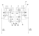
- 1 is an equivalent circuit diagram showing a configuration example of a pixel and a pixel circuit according to a first embodiment of the present technology.
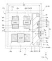
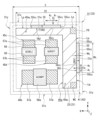
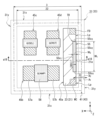
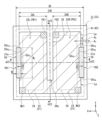
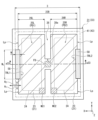
- 1 is a plan view illustrating a schematic configuration example of one pixel in a solid-state imaging device according to a first embodiment of the present technology;
- FIG. 4B is an enlarged plan view of a portion of FIG. 4A.
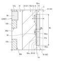
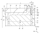
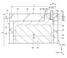
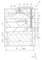
- 4B is a longitudinal sectional view showing a schematic longitudinal sectional structure taken along the a4-a4 cutting line in FIG. 4A.
- FIG. 5B is an enlarged plan view of a portion of FIG. 5A.
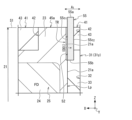
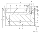
- 4B is a longitudinal sectional view showing a schematic longitudinal sectional structure taken along the b4-b4 cutting line in FIG. 4A.
- 3A to 3C are longitudinal cross-sectional views each showing a schematic process of a method for manufacturing a solid-state imaging device according to a first embodiment of the present technology.
- FIG. 7B is a vertical cross-sectional view showing a schematic process following FIG. 7A.
- FIG. 7C is a vertical cross-sectional view showing a schematic diagram of a step following FIG. 7B.
- FIG. 7D is a vertical cross-sectional view showing a schematic process following FIG. 7C.
- FIG. 7B is a vertical cross-sectional view showing a schematic process following FIG.
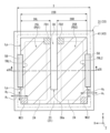
- FIG. 1 is a diagram showing a modified example 1-1 according to the first embodiment of the present technology, and is a plan view diagrammatically showing one pixel.
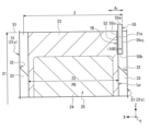
- 8B is a longitudinal sectional view showing a schematic longitudinal sectional structure taken along the a8-a8 cutting line in FIG. 8A.
- FIG. 13 is a diagram showing Modification 1-2 according to the first embodiment of the present technology, and is a plan view diagrammatically showing one pixel.
- 9B is a longitudinal sectional view showing a schematic longitudinal sectional structure taken along the a9-a9 cutting line in FIG. 9A.
- FIG. 11 is a diagram showing Modification 1-3 according to the first embodiment of the present technology, and is a plan view showing one pixel in schematic form.
- FIG. 10B is a longitudinal sectional view showing a schematic longitudinal sectional structure taken along the a10-a10 cutting line in FIG. 10A.
- FIG. 13 is a diagram showing a modified example 1-4 according to the first embodiment of the present technology, and is a plan view showing one pixel in schematic form.
- 11B is a longitudinal sectional view showing a schematic longitudinal sectional structure taken along the a11-a11 cutting line in FIG. 11A.
- FIG. 13 is a diagram showing Modification 1-5 according to the first embodiment of the present technology, and is a plan view showing one pixel in schematic form.
- 12B is a longitudinal sectional view showing a schematic longitudinal sectional structure taken along the a12-a12 cutting line in FIG. 12A.
- FIG. 13 is a diagram showing a modified example 1-6 according to the first embodiment of the present technology, and is a plan view showing one pixel in schematic form.
- FIG. 13 is a diagram showing Modification 1-7 according to the first embodiment of the present technology, and is a plan view diagrammatically showing one pixel.
- FIG. 13 is a diagram showing Modification 1-8 according to the first embodiment of the present technology, and is a plan view showing one pixel in schematic form.
- FIG. 13 is a diagram showing Modification 1-9 according to the first embodiment of the present technology, and is a plan view showing one pixel in schematic form.
- FIG. 10 is a diagram showing a modified example 1-10 according to the first embodiment of the present technology, and is a plan view showing one pixel in schematic form.
- FIG. 17B is a longitudinal sectional view showing a schematic longitudinal sectional structure taken along the a17-a17 cutting line in FIG. 17A.
- FIG. 11 is a diagram showing Modification 1-11 according to the first embodiment of the present technology, and is a plan view showing one pixel in schematic form.
- 17B is a longitudinal sectional view showing a schematic longitudinal sectional structure taken along the a17-a17 cutting line in FIG. 17A.
- FIG. 13 is a diagram showing Modification 1-12 according to the first embodiment of the present technology, and is a plan view diagrammatically showing one pixel.
- FIG. 13 is a diagram showing Modification 1-13 according to the first embodiment of the present technology, and is a plan view diagrammatically showing one pixel.
- FIG. 11 is an equivalent circuit diagram illustrating a configuration example of a pixel and a pixel circuit in a solid-state imaging device according to a second embodiment of the present technology.
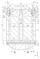
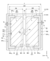
- FIG. 13 is a plan view illustrating a schematic configuration example of one pixel in a solid-state imaging device according to a second embodiment of the present technology.
- FIG. 20B is a longitudinal sectional view showing a schematic longitudinal sectional structure taken along the a20-a20 cutting line in FIG. 20B.
- FIG. 13 is a diagram showing a modified example 2-1 according to the second embodiment of the present technology, and is a plan view diagrammatically showing a configuration example of one pixel.
- 21B is a longitudinal sectional view showing a schematic longitudinal sectional structure taken along the a21-a21 cutting line in FIG.
- 21A. 21B is a longitudinal cross-sectional view showing a schematic longitudinal cross-sectional structure taken along the b21-b21 cutting line in FIG. 21A.
- FIG. 13 is a diagram showing a modified example 2-2 according to the second embodiment of the present technology, and is a plan view diagrammatically showing a configuration example of one pixel.
- 22B is a longitudinal sectional view showing a schematic longitudinal sectional structure taken along the a22-a22 cutting line in FIG. 22A.
- FIG. 13 is a diagram showing a modified example 2-3 according to the second embodiment of the present technology, and is a plan view diagrammatically showing a configuration example of one pixel.
- 23B is a longitudinal sectional view showing a schematic longitudinal sectional structure taken along the a23-a23 cutting line in FIG.
- FIG. 13 is a diagram showing a modified example 2-4 according to the second embodiment of the present technology, and is a plan view diagrammatically showing a configuration example of one pixel.
- 24B is a longitudinal sectional view showing a schematic longitudinal sectional structure taken along the a24-a24 cutting line in FIG. 24A.
- FIG. 13 is a diagram showing a modified example 2-5 according to the second embodiment of the present technology, and is a plan view showing one pixel in schematic form.
- FIG. 13 is a diagram showing a modified example 2-6 according to the second embodiment of the present technology, and is a plan view diagrammatically showing a configuration example of one pixel.
- 26B is a longitudinal sectional view showing a schematic longitudinal sectional structure taken along the a26-a26 cutting line in FIG. 26A.
- FIG. 13 is a diagram showing a modified example 2-7 according to the second embodiment of the present technology, and is a plan view diagrammatically showing a configuration example of one pixel.
- 27B is a longitudinal cross-sectional view showing a schematic longitudinal cross-sectional structure taken along the a27-a27 cutting line in FIG. 27A.
- FIG. 13 is a diagram showing a modified example 2-8 according to the second embodiment of the present technology, and is a plan view showing one pixel in schematic form.
- FIG. 13 is a diagram showing a modified example 2-9 according to the second embodiment of the present technology, and is a plan view showing one pixel in schematic form.
- FIG. 13 is a diagram showing a modified example 2-10 of the second embodiment of the present technology, and is a plan view showing one pixel in schematic form.
- FIG. 11 is a diagram showing a modified example 2-11 according to the second embodiment of the present technology, and is a plan view showing one pixel in schematic form.
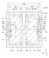
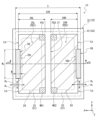
- FIG. 13 is a plan view illustrating a schematic configuration example of one pixel in a solid-state imaging device according to a third embodiment of the present technology.
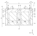
- FIG. 32B is a longitudinal cross-sectional view showing a schematic longitudinal cross-sectional structure taken along the a32-a32 cutting line in FIG. 32A.
- FIG. 13 is a diagram showing a modified example 3-1 according to the third embodiment of the present technology, and is a plan view diagrammatically showing a configuration example of one pixel.
- 33B is a longitudinal cross-sectional view showing a schematic longitudinal cross-sectional structure taken along the a33-a33 cutting line in FIG. 33A.
- FIG. 13 is a diagram illustrating a modified example 3-2 according to the third embodiment of the present technology, and is a plan view diagrammatically illustrating a configuration example of one pixel.
- FIG. 34B is a longitudinal sectional view showing a schematic longitudinal sectional structure taken along the a34-a34 cutting line in FIG. 34A.
- FIG. 13 is a diagram illustrating a modified example 3-3 according to the third embodiment of the present technology, and is a plan view diagrammatically illustrating a configuration example of one pixel.
- 35B is a longitudinal cross-sectional view showing a schematic longitudinal cross-sectional structure taken along the a35-a35 cutting line in FIG. 35A.
- 13 is a plan view illustrating a schematic configuration example of one pixel in a solid-state imaging device according to a fourth embodiment of the present technology.
- FIG. 36B is a longitudinal cross-sectional view showing a schematic longitudinal cross-sectional structure taken along the a36-a36 cutting line in FIG.
- FIG. 13 is an exploded view illustrating a schematic configuration example of a solid-state imaging device according to a fifth embodiment of the present technology.
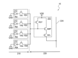
- FIG. 13 is an equivalent circuit diagram showing a configuration example of a pixel and a pixel circuit according to a fifth embodiment of the present technology.
- FIG. 13 is a diagram showing a schematic configuration of an electronic device according to a sixth embodiment of the present technology.
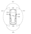
- FIG. 23 is a block diagram showing an example of a schematic configuration of a vehicle control system according to a seventh embodiment of the present technology. 4 is an explanatory diagram showing an example of the installation positions of an outside-vehicle information detection unit and an imaging unit;
- FIG. FIG. 23 is a diagram showing an example of a schematic configuration of an endoscopic surgery system according to an eighth embodiment of the present technology.
- 2 is a block diagram showing an example of the functional configuration of a camera head and a CCU.
- up and down and other directions in the following explanation are merely for the convenience of explanation and do not limit the technical ideas of this technology. For example, if an object is rotated 90 degrees and observed, up and down are converted into left and right and read, and of course, if it is rotated 180 degrees and observed, up and down are read inverted.
- a first direction and a second direction mutually orthogonal in the same plane are defined as an X direction and a Y direction, respectively, and a third direction perpendicular to each of the first direction and the second direction is defined as a Z direction.
- the thickness direction of a semiconductor layer 21 described later will be described as the Z direction.
- the Z direction will be described as "one direction" of the present technology.
- the thickness of the semiconductor layer 21 is the distance between the first surface portion S1 and the second surface portion S2, which are located on opposite sides in the Z direction, and the thickness direction of the semiconductor layer 21 is the direction that represents the thickness of the semiconductor layer 21.
- a planar view refers to the semiconductor layer 21 being viewed from the Z direction (one direction).
- a cross-sectional view refers to the cross section along the Z direction (one direction) being viewed from a direction perpendicular to the Z direction.
- CMOS complementary metal oxide semiconductor
- the solid-state imaging device 1A is mainly composed of a semiconductor chip 2 having a rectangular two-dimensional planar shape when viewed in a plane. That is, the solid-state imaging device 1A is mounted on the semiconductor chip 2, and the semiconductor chip 2 can be regarded as the solid-state imaging device 1A. As shown in Fig. 1, the solid-state imaging device 1A according to the first embodiment of the present technology is mainly composed of a semiconductor chip 2 having a rectangular two-dimensional planar shape when viewed in a plane. That is, the solid-state imaging device 1A is mounted on the semiconductor chip 2, and the semiconductor chip 2 can be regarded as the solid-state imaging device 1A. As shown in Fig.
- this solid-state imaging device 1A takes in image light (incident light 306) from a subject via an optical lens 302, converts the amount of incident light 306 formed on an imaging surface into an electrical signal on a pixel-by-pixel basis, and outputs the electrical signal as a pixel signal.
- the semiconductor chip 2 on which the solid-state imaging device 1A is mounted has a square pixel array section 2A located in the center of a two-dimensional plane including mutually orthogonal X and Y directions, and a peripheral section 2B located outside the pixel array section 2A so as to surround the pixel array section 2A.
- the semiconductor chip 2 is formed in the manufacturing process by dicing a semiconductor wafer including a semiconductor layer 21 described below into chip formation regions. Therefore, the configuration of the solid-state imaging device 1A described below is generally the same in the wafer state before the semiconductor wafer is diced. Therefore, this technology can be applied in the semiconductor chip state and in the semiconductor wafer state.
- the pixel array section 2A shown in FIG. 1 is, for example, a light receiving surface that receives light collected by an optical lens (optical system) 302 shown in FIG. 39.
- a plurality of pixels 3 (sensor pixels) are arranged in a matrix on a two-dimensional plane including the X direction and the Y direction.
- the pixels 3 are repeatedly arranged in each of the X direction and the Y direction that are mutually orthogonal within the two-dimensional plane.
- a plurality of bonding pads 14 are arranged in the peripheral portion 2B.
- Each of the plurality of bonding pads 14 is arranged, for example, along each of the four sides of the semiconductor chip 2 in a two-dimensional plane.
- Each of the plurality of bonding pads 14 functions as an input/output terminal that electrically connects the semiconductor chip 2 to an external device.
- the semiconductor chip 2 includes a logic circuit 13 shown in Fig. 2.
- the logic circuit 13 includes a vertical drive circuit 4, a column signal processing circuit 5, a horizontal drive circuit 6, an output circuit 7, and a control circuit 8.
- the logic circuit 13 is configured of a CMOS (Complementary MOS) circuit having, as field effect transistors, for example, n-channel conductivity type MOSFETs (Metal Oxide Semiconductor Field Effect Transistors) and p-channel conductivity type MOSFETs.
- CMOS Complementary MOS
- the vertical drive circuit 4 shown in FIG. 2 is composed of, for example, a shift register.
- the vertical drive circuit 4 sequentially selects the desired pixel drive lines 10, supplies pulses to the selected pixel drive lines 10 for driving the pixels 3, and drives each pixel 3 row by row. That is, the vertical drive circuit 4 sequentially selects and scans each pixel 3 in the pixel array section 2A vertically row by row, and supplies pixel signals from the pixels 3 based on signal charges generated by the photoelectric conversion section 25 (see FIG. 3) of each pixel 3 according to the amount of light received to the column signal processing circuit 5 via the vertical signal line 11.
- the column signal processing circuit 5 shown in FIG. 2 is arranged, for example, for each column of pixels 3, and performs signal processing such as noise removal for each pixel column on signals output from one row of pixels 3.
- the column signal processing circuit 5 performs signal processing such as CDS (Correlated Double Sampling) and AD (Analog-to-Digital) conversion to remove pixel-specific fixed pattern noise.
- the horizontal drive circuit 6 shown in FIG. 2 is composed of, for example, a shift register.
- the horizontal drive circuit 6 sequentially outputs horizontal scanning pulses to the column signal processing circuits 5, thereby selecting each of the column signal processing circuits 5 in turn, and causing each of the column signal processing circuits 5 to output a pixel signal that has been subjected to signal processing to the horizontal signal line 12.
- the output circuit 7 shown in FIG. 2 processes and outputs pixel signals sequentially supplied from each of the column signal processing circuits 5 through the horizontal signal line 12.
- the signal processing may include buffering, black level adjustment, column variation correction, various types of digital signal processing, etc.
- the control circuit 8 shown in FIG. 2 generates clock signals and control signals that serve as the basis for the operation of the vertical drive circuit 4, column signal processing circuit 5, horizontal drive circuit 6, etc., based on the vertical synchronization signal, horizontal synchronization signal, and master clock signal. The control circuit 8 then outputs the generated clock signals and control signals to the vertical drive circuit 4, column signal processing circuit 5, horizontal drive circuit 6, etc.
- each of the plurality of pixels 3 includes a photoelectric conversion unit 25, a floating diffusion region (floating diffusion region) FD as a charge holding unit that holds (accumulates) signal charges photoelectrically converted by the photoelectric conversion unit 25, and a transfer transistor TR that transfers the signal charges photoelectrically converted by the photoelectric conversion unit 25 to the floating diffusion region FD.
- Each of the plurality of pixels 3 further includes a photoelectric conversion region (photoelectric conversion cell) 22 of the semiconductor layer 21 shown in Fig. 5A.
- Each of the photoelectric conversion unit 25, the floating diffusion region FD, and the transfer transistor TR are provided in the photoelectric conversion region 22 as shown in Figs. 4A and 5A.
- Photoelectric conversion section 3 is configured by, for example, a pn junction type photodiode (PD) and generates a signal charge according to the amount of received light.
- the photoelectric conversion unit 25 also temporarily holds (accumulates) the generated signal charge.
- the cathode side of the photoelectric conversion unit 25 is electrically connected to the source region of the transfer transistor TR, and the anode side is electrically connected to a reference potential line (e.g., ground).
- a reference potential line e.g., ground
- Transfer transistor 3 transfers the signal charge photoelectrically converted by the photoelectric conversion unit 25 to the floating diffusion region FD.
- the source region of the transfer transistor TR is electrically connected to the cathode side of the photoelectric conversion unit 25, and the drain region is electrically connected to the floating diffusion region FD.
- the gate electrode of the transfer transistor TR is electrically connected to a transfer transistor drive line of the pixel drive line 10 shown in FIG.
- the floating diffusion region FD shown in FIG. 3 temporarily accumulates and holds the signal charge transferred from the photoelectric conversion unit 25 via the transfer transistor TR.
- the solid-state imaging device 1A (semiconductor chip 2) according to the first embodiment includes a pixel circuit (readout circuit) 15 shown in Fig. 3. As shown in Fig. 3, the pixel circuit 15 is electrically connected to a floating diffusion region FD of the photoelectric conversion region 22.
- a circuit configuration is used in which one pixel circuit 15 is assigned to one pixel 3, but the present invention is not limited to this first embodiment.
- a circuit configuration may be used in which one pixel circuit 15 is shared by multiple pixels 3.
- a circuit configuration may be used in which one pixel circuit 15 is shared by one pixel group (photoelectric conversion group) in which four pixels 3 are arranged in a 2 ⁇ 2 arrangement, two in each of the X and Y directions, as one unit.
- a circuit configuration may be used in which one pixel circuit 15 is shared by one pixel group (photoelectric conversion group) in which two pixels 3 are arranged as one unit.
- a circuit configuration may be used in which one pixel circuit 15 is shared by one pixel group (photoelectric conversion group) in which four or more pixels 3 are arranged as one unit.
- the pixel circuit 15 shown in FIG. 3 reads out the signal charge held in the floating diffusion region FD and outputs a pixel signal based on the read-out signal charge.
- the pixel circuit 15 converts the signal charge photoelectrically converted by the photoelectric conversion unit 25 (photodiode PD) into a pixel signal based on this signal charge and outputs it.
- the pixel circuit 15 includes a plurality of pixel transistors Q.
- the pixel circuit 15 of the first embodiment includes, but is not limited to, an amplification transistor AMP, a selection transistor SEL, and a reset transistor RST as the pixel transistors Q.
- These pixel transistors Q (AMP, SEL, RST) and the transfer transistor TR described above are configured as insulated gate type field effect transistors, for example, MOSFETs (Metal Oxide Semiconductor Field Effect Transistors) whose gate insulating film is made of a silicon oxide (SiO 2 ) film.
- MOSFETs Metal Oxide Semiconductor Field Effect Transistors
- These transistors may also be MISFETs (Metal Insulator Semiconductor FETs) whose gate insulating film is made of a silicon nitride (Si 3 N 4 ) film or a laminated film of a silicon nitride film and a silicon oxide film.
- MISFETs Metal Insulator Semiconductor FETs
- the selection transistor SEL and the reset transistor RST function mainly as switching elements.
- the remaining amplification transistor AMP functions mainly as an amplification element.
- the source region of the amplifier transistor AMP is electrically connected to the drain region of the select transistor SEL, and the drain region is electrically connected to the power supply line Vdd and the drain region of the reset transistor RST.
- the gate electrode of the amplifier transistor AMP is electrically connected to the floating diffusion region FD and the source region of the reset transistor RST.
- the source of the selection transistor SEL is electrically connected to the vertical signal line 11 (VSL), and the drain region is electrically connected to the source region of the amplification transistor AMP.
- the gate electrode of the selection transistor SEL is electrically connected to the selection transistor drive line of the pixel drive line 10 shown in FIG. 2.
- the source region of the reset transistor RST is electrically connected to the floating diffusion region FD and the gate electrode of the amplifier transistor AMP, and the drain region is electrically connected to the power supply line Vdd and the drain region of the amplifier transistor AMP.
- the gate electrode of the reset transistor RST is electrically connected to the reset transistor drive line of the pixel drive line 10 shown in FIG. 2.
- the transfer transistor TR shown in FIG. 3 When the transfer transistor TR shown in FIG. 3 is turned on, it transfers the signal charge generated in the photoelectric conversion unit 25 to the floating diffusion region FD.
- the selection transistor SEL shown in FIG. 3 controls the output timing of the pixel signal from the pixel circuit 15.
- the amplification transistor AMP shown in FIG. 3 generates a pixel signal whose voltage corresponds to the level of the signal charge held in the floating diffusion region FD.
- the amplification transistor AMP constitutes a source-follower type amplifier, and outputs a pixel signal whose voltage corresponds to the level of the signal charge generated in the photoelectric conversion unit 25.
- the selection transistor SEL is turned on, the amplification transistor AMP amplifies the potential of the floating diffusion region FD, and outputs a voltage corresponding to the potential to the column signal processing circuit 5 via the vertical signal line 11 (VSL).
- the signal charge generated in the photoelectric conversion unit 25 of the pixel 3 is held (accumulated) in the floating diffusion region FD via the transfer transistor TR of the pixel 3.
- the signal charge held in the floating diffusion region FD is read out by the pixel circuit 15 and applied to the gate electrode of the amplification transistor AMP of the pixel circuit 15.
- a horizontal line selection control signal is provided to the gate electrode of the selection transistor SEL of the pixel circuit 15 from the vertical shift register.
- the selection transistor SEL becomes conductive, and a current corresponding to the potential of the floating diffusion region FD amplified by the amplification transistor AMP flows in the vertical signal line 11. Also, by setting the reset control signal applied to the gate electrode of the reset transistor RST of the pixel circuit 15 to a high (H) level, the reset transistor RST becomes conductive, and the signal charge accumulated in the floating diffusion region FD is reset.
- the selection transistor SEL may be omitted if necessary.
- the source region of the amplification transistor AMP is electrically connected to the vertical signal line 11 (VSL).
- a switching transistor may also be provided between the reset transistor RST and the gate electrode of the floating diffusion region FD and the amplifier transistor AMP.
- the switching transistor controls charge retention by the floating diffusion region FD and adjusts the voltage multiplication factor according to the potential amplified by the amplifier transistor AMP.
- the switching transistor is also used to switch the conversion efficiency.
- the FD capacitance C of the charge holding section needs to be large so that the voltage V when converted to voltage by the amplification transistor AMP does not become too large (in other words, so that it becomes small).
- the switching transistor when the switching transistor is turned on, the gate capacitance of the switching transistor increases, so the overall FD capacitance C becomes large.
- the switching transistor when the switching transistor is turned off, the overall FD capacitance C becomes small. In this way, by switching the switching transistor on/off, the FD capacitance C can be made variable and the conversion efficiency can be switched.
- Figures 4A to 6 illustrate the multilayer wiring layer, which will be described later, is omitted from Figures 4A to 6. Also, while Figure 1 illustrates the light incident surface side of the semiconductor chip 2, Figure 4A illustrates the photoelectric conversion region 22 as seen from the side opposite the light incident surface side of the semiconductor chip 2 (the multilayer wiring layer side).
- the semiconductor chip 2 includes a semiconductor layer 21 having a first surface portion S1 and a second surface portion S2 located on opposite sides in a Z direction (thickness direction) as one direction, an inter-pixel isolation region 31 provided in the semiconductor layer 21 and serving as an isolation region extending in the thickness direction (Z direction) of the semiconductor layer 21, and a photoelectric conversion region 22 provided in the semiconductor layer 21 and partitioned by the inter-pixel isolation region 31, and including the first surface portion S1 and the second surface portion S2 of the semiconductor layer 21.
- the semiconductor chip 2 further includes a multi-layer wiring layer provided on the first surface S1 side of the semiconductor layer 21.
- the semiconductor chip 2 further includes, on the second surface S2 side of the semiconductor layer 21, a planarization film 61, an optical filter layer 63, and a lens layer 64, which are provided in this order from the second surface S2 side.
- the first surface S1 of the semiconductor layer 21 is sometimes called the main surface or element formation surface, and the second surface S2 is sometimes called the back surface.
- the solid-state imaging device 1A photoelectrically converts incident light incident from the second surface S2 side of the semiconductor layer 21 by a photoelectric conversion section 25 (photodiode PD) provided in the photoelectric conversion region 22 of the semiconductor layer 21. Therefore, in this first embodiment, the second surface S2 of the semiconductor layer 21 is sometimes called the light incident surface.
- planarization film 61 is provided on the second surface S2 side of the semiconductor layer 21 so as to cover the second surface S2 of the semiconductor layer 21 and planarize the second surface S2 side of the semiconductor layer 21.
- the optical filter layer 63 is provided on the opposite side of the planarization film 61 from the semiconductor layer 21 side.
- This optical filter layer 63 separates the incident light from the light incident surface side (second surface portion S2 side) of the semiconductor chip 2 into colors.
- This optical filter layer 63 includes an optical filter portion 63a for each pixel 3 (for each photoelectric conversion region 22) that transmits light of a specific wavelength, such as, but not limited to, red (R), green (G), or blue (B).
- the lens layer 64 is provided on the side of the optical filter layer 63 opposite the planarization film 61.
- the lens layer 64 includes a microlens (on-chip lens) 64a for each pixel 3 (for each photoelectric conversion region 22) that collects the irradiated light and efficiently directs the collected light into the photoelectric conversion region 22.
- the pixel 3 of this first embodiment includes a photoelectric conversion region 22, and a planarization film 61, an optical filter portion 63a, and a microlens 64 provided on the second surface portion S2 side of the photoelectric conversion region 22.
- the semiconductor layer 21 includes an inter-pixel isolation region 31 extending in the thickness direction (Z direction) of the semiconductor layer 21, and a photoelectric conversion region 22 partitioned by the inter-pixel isolation region 31.
- the photoelectric conversion region 22 is provided for each pixel 3.
- the semiconductor layer 21 may be a Si substrate, a SiGe substrate, an InGaAs substrate, or the like.
- a p-type semiconductor substrate made of single crystal silicon, for example, is used as the semiconductor layer 21.
- first extending portions 31x extending in the X direction are repeatedly arranged at a predetermined interval in the Y direction.
- second extending portions 31y extending in the Y direction are repeatedly arranged at a predetermined interval in the X direction. That is, the plane pattern of the inter-pixel isolation region 31 in a plan view is a lattice-like plane pattern.
- the pixel separation region 31 corresponding to one photoelectric conversion region 22 has a rectangular annular planar pattern (ring-shaped planar pattern) in a plan view, and surrounds the periphery of one photoelectric conversion region 22.
- the inter-pixel isolation region 31 extends in the thickness direction (Z direction) in which the first surface portion S1 and the second surface portion S2 of the semiconductor layer 21 are separated from each other.
- the inter-pixel isolation region 31 electrically and optically isolates two adjacent photoelectric conversion regions 22 when the semiconductor layer 21 is viewed in plan from the thickness direction (Z direction) of the semiconductor layer 21.
- the inter-pixel isolation region 31 is, for example, but not limited to, configured as a trench isolation type including a recessed portion 32 extending in the thickness direction (Z direction) of the semiconductor layer 21 and an isolation insulating film 33 provided in the recessed portion 32. As shown in Figs. 4A and 5A, the inter-pixel isolation region 31 overlaps with an inter-element isolation region 41 provided on the first surface S1 side of the semiconductor layer 21 and extends from the bottom of the inter-element isolation region 41 to the second surface S2 of the semiconductor layer 21, although this is not limited to this.
- the isolation insulating film 33 for example, a silicon oxide film can be used.
- the photoelectric conversion region 22 is surrounded by the inter-pixel isolation region 31 in a plan view (a plan view when the semiconductor layer 21 is viewed from the thickness direction of the semiconductor layer 21), and has a rectangular planar shape. Specifically, the photoelectric conversion region 22 is surrounded by two first extension parts 31x that extend in the X direction and are spaced apart in the Y direction, and two second extension parts 31y that extend in the Y direction and are spaced apart in the X direction, in the inter-pixel isolation region 31. The photoelectric conversion region 22 is partitioned by the inter-pixel isolation region 31 including the first extension parts 31x and the second extension parts 31y, and is separated from other photoelectric conversion regions 22. That is, the photoelectric conversion region 22 is adjacent to other photoelectric conversion regions 22 via the inter-pixel isolation region 31 in each of the X direction and the Y direction.
- the photoelectric conversion region 22 has a p-type well region 23 consisting of a p-type semiconductor region provided in the semiconductor layer 21 across the first surface portion S1 and the second surface portion S2 of the semiconductor layer 21, an n-type semiconductor region 24 provided in the p-type well region 23 away from the first surface portion S1 of the semiconductor layer 21, and a photoelectric conversion section 25 including the p-type well region 23 and the n-type semiconductor region 24, and provided in the semiconductor layer 21 away from the first surface portion S1 of the semiconductor layer 21.
- the photoelectric conversion region 22 further includes an n-type floating diffusion region FD as a charge holding section that holds the signal charge photoelectrically converted by the photoelectric conversion section 25, and a transfer transistor TR that transfers the signal charge photoelectrically converted by the photoelectric conversion section 25 to the n-type floating diffusion region FD.
- the photoelectric conversion region 22 further includes an element isolation region (field isolation region) 41 as an isolation region provided on the first surface portion S1 side of the semiconductor layer 21, and each of island-shaped element formation regions (active regions) 45a, 45b, 45c, and 45d partitioned by the element isolation region 41.
- element isolation region field isolation region
- the photoelectric conversion region 22 further includes, as the pixel transistor Q included in the pixel circuit 15 in FIG. 3, for example, an amplification transistor AMP, a selection transistor SEL, and a reset transistor RST. Moreover, the photoelectric conversion region 22 further includes a p-type power supply contact region WC.
- the inter-element isolation region 41 is provided in a surface layer portion on the first surface portion S1 side of the semiconductor layer 21.
- the inter-element isolation region 41 overlaps with the inter-pixel isolation region 31 in a plan view and is integrated with the inter-pixel isolation region 31.
- the inter-element isolation region 41 extends from the first surface S1 side of the semiconductor layer 21 toward the second surface S2 side, and has a thickness in the thickness direction (Z direction) of the semiconductor layer 21.
- the inter-element isolation region 41 has, but is not limited to, an STI (Shallow Trench Isolation) structure in which an isolation insulating film 43 is selectively embedded in a shallow groove portion 42 recessed from the first surface S1 to the second surface S2 side of the semiconductor layer 21.
- the inter-element isolation region 41 is provided across adjacent photoelectric conversion regions 22 via the inter-pixel isolation region 31 in a planar view.
- the region where the inter-element isolation region 41 and the inter-pixel isolation region 31 overlap can be regarded as an isolation region including the inter-element isolation region 41 and the inter-pixel isolation region 31.
- the inter-element isolation region 41 included in this isolation region can be regarded as a first isolation region
- the inter-pixel isolation region 31 included in this isolation region can be regarded as a second isolation region.
- the inter-element isolation region 41 and the inter-pixel isolation region 31 can be regarded as separate isolation regions.
- Each of the element formation regions 45a, 45b, 45c, and 45d included in the photoelectric conversion region 22 has a planar layout shown in FIG. 4A as an example, but is not limited to this.
- the element formation region 45a is disposed on one side (the right side in the figure) of two sides that are opposite to each other in the X direction of the photoelectric conversion region 22 in a plan view, and extends in the Y direction.
- the element formation region 5b is disposed on one side (the lower side in the figure) of two sides that are opposite to each other in the Y direction of the photoelectric conversion region 22 in a plan view, and extends in the X direction. Also, as shown in FIG.
- each of the element formation regions 45c and 45d is disposed side by side in the X direction on the other side (the upper side in the figure) of two sides that are opposite to each other in the Y direction of the photoelectric conversion region 22 in a plan view, and extends in the Y direction.
- each of the element formation regions 45b, 45c, and 45d is disposed between the element formation region 45a and the inter-pixel isolation region 31 in a plan view.
- the planar shape of each of the element formation regions 45a, 45b, 45c, and 45d is, for example, a square shape.
- the p-type well region 23 is provided over a wide area in the photoelectric conversion region 22, extending across the first surface portion S1 side and the second surface portion S2 side of the semiconductor layer 21.
- the p-type well region 23 contacts the inter-pixel isolation region 31 along the thickness direction (Z direction) of the semiconductor layer 21.
- the p-type well region 23 is composed of a p-type semiconductor region.
- the n-type semiconductor region 24 is provided in the p-type well region 23 in the photoelectric conversion region 22. That is, the n-type semiconductor region 24 is surrounded by the p-type well region 23 on six sides, including the top surface, bottom surface, and four side surfaces. The n-type semiconductor region 24 is separated from the first surface portion S1 and the second surface portion S2 of the semiconductor layer 21, and the inter-pixel isolation region 31.
- Photoelectric conversion section 5A and 6 includes a p-type well region 23 and an n-type semiconductor region 24 in each photoelectric conversion region 22.
- the photoelectric conversion unit 25 is configured as a pn junction type photodiode (PD) including a pn junction between the p-type well region 23 and the n-type semiconductor region 24.
- PD pn junction type photodiode
- the photoelectric conversion unit 25 photoelectrically converts light incident on the n-type semiconductor region 24 from the second surface S2 side of the semiconductor layer 21 into a signal charge in the n-type semiconductor region 24, and temporarily holds (accumulates) the photoelectrically converted signal charge at the pn junction between the p-type well region 23 and the n-type semiconductor region 24.
- the photoelectric conversion unit 25 is provided in the semiconductor layer 21, spaced apart from the first surface S1 of the semiconductor layer 21.
- the n-type floating diffusion region FD is provided in the element formation region 45a.
- the n-type floating diffusion region FD is disposed on one side (upper side in the figure) of two sides of the element formation region 45a that are opposite to each other in the Y direction.
- the n-type floating diffusion region FD is not shown in detail, but as will be described with reference to FIG. 5A, it is provided in the p-type well region 23 on the first surface portion S1 side of the semiconductor layer 21.
- the n-type floating diffusion region FD overlaps with the photoelectric conversion section 25 (n-type semiconductor region 24) in a plan view, and is separated from the photoelectric conversion section 25 (n-type semiconductor region 24) in the thickness direction (Z direction) of the semiconductor layer 21. That is, the p-type well region 23 is provided between the n-type floating diffusion region FD and the n-type semiconductor region 24.
- the n-type floating diffusion region FD is configured with a higher impurity concentration than the n-type semiconductor region 24.
- the p-type power supply contact region WC is provided in the element formation region 45a.
- the p-type power supply contact region WC is disposed on the other side (lower side in the figure) of two sides of the element formation region 45a that are opposite to each other in the Y direction.
- the p-type power supply contact region WC is not shown in detail, but as will be described with reference to FIG. 5A, it is provided in the p-type well region 23 on the first surface portion S1 side of the semiconductor layer 21.
- the p-type power supply contact region WC is composed of a p-type semiconductor region with a higher impurity concentration than the p-type well region 23, and is electrically connected to the p-type well region 23.
- a first reference potential (Vss potential) of, for example, 0V is applied to this p-type power supply contact region WC during operation as a reference potential in the semiconductor chip 2 (in the solid-state imaging device 1A).
- Vss potential Vs potential
- the amplification transistor AMP is provided in the element formation region 45b. That is, the amplification transistor AMP is provided on the first surface portion S1 side of the semiconductor layer 21 in the photoelectric conversion region 22.
- the amplification transistor AMP has a gate electrode 56 provided on the upper surface portion side (the first surface portion S1 side of the semiconductor layer 21) of the element formation region 45b so as to overlap with the element formation region 45b, and a gate insulating film 52 interposed between the gate electrode 56 and the element formation region 45b.
- the amplification transistor AMP further has a pair of main electrode regions 57a and 57b that are provided in the element formation region 45b on both sides in the gate length direction of the gate electrode 56 and function as a source region and a drain region.
- the amplification transistor AMP further has a channel formation portion provided in the element formation region 45b that overlaps with the gate electrode 56 in a plan view.
- the pair of main electrode regions 57a and 57b are separated from each other via a channel forming portion.
- Each of the pair of main electrode regions 57a and 57b is composed of an n-type semiconductor region having a higher impurity concentration than the n-type semiconductor region 24.
- the channel forming portion is composed of a p-type well region 23.
- the selection transistor SEL is provided in the element formation region 45c. Furthermore, among the pixel transistors Q included in the pixel circuit 15, the reset transistor RST is provided in the element formation region 45d.
- Each of the selection transistor SEL and the reset transistor RST is basically configured in the same way as the amplification transistor AMP, so detailed explanations are omitted.
- each of the selection transistor SEL and the reset transistor RST the gate electrode and a pair of main electrode regions are given the same reference numerals as the gate electrode 56 and a pair of main electrode regions 57a, 57b of the amplification transistor AMP.
- each of the selection transistor SEL and the reset transistor TST is provided on the first surface portion S1 side of the semiconductor layer 21 in the photoelectric conversion region 22, similar to the amplification transistor AMP shown in FIG.
- the transfer transistor TR is provided on the edge side of the element formation region 45a included in the photoelectric conversion region 22.
- the transfer transistor TR has a gate electrode 55 extending in the thickness direction (Z direction) of the semiconductor layer 21 between the semiconductor layer 21 of the photoelectric conversion region 22 and the insulator (isolation insulating film 43 and 33) adjacent to each other and the insulator (isolation insulating film 43 and 33).
- the transfer transistor TR further has a gate insulating film 52 interposed between the gate electrode 55 and the semiconductor layer 21.
- the transfer transistor TR further has a p-type well region 23 functioning as a channel formation portion where a channel is formed, and an n-type floating diffusion region FD and an n-type semiconductor region 24 functioning as a source region and a drain region.
- the transfer transistor TR has a vertical structure in which the gate electrode 55 extends in the thickness direction (Z direction) of the semiconductor layer 21.
- the gate electrode 55 extends in the thickness direction (Z direction) of the semiconductor layer 21 across the isolation insulating film 43 of the inter-element isolation region 41 and the isolation insulating region 33 of the inter-pixel isolation region 31 in a region where the inter-element isolation region 41 and the inter-pixel isolation region 31 overlap in a plan view.
- the gate electrode 55 of the first embodiment is adjacent to the semiconductor layer 21 between the semiconductor layer 21 and the isolation insulating films 43 and 33, and extends in the thickness direction (Z direction) of the semiconductor layer 21 adjacent to each of the isolation insulating films 43 and 33.
- the isolation insulating film 43 of the inter-element isolation region 41 and the isolation insulating film 33 of the inter-pixel isolation region 31 correspond to a specific example of “insulator” in the present technology.
- the isolation insulating film 43 corresponds to a specific example of “first isolation insulating film” in the present technology
- the isolation insulating film 33 corresponds to a specific example of “second isolation insulating film” in the present technology.
- the isolation insulating film 43 of the inter-element isolation region 41 and the isolation insulating film 33 of the inter-pixel isolation region 31 are integrated, the isolation insulating film 43 and the isolation insulating film 33 can be regarded as a single "insulator.” Therefore, in this first embodiment, the gate electrode 55 is adjacent to the side wall surface portion 21a of the semiconductor layer 21 outside the photoelectric conversion region 22, and is adjacent to the insulators including the isolation insulating films 43 and 33 and extends along the thickness direction (Z direction) of the semiconductor layer 21.
- a direction crossing the interface Lp between the semiconductor layer 21 and the insulator (isolation insulating film 43 and 33) in the photoelectric conversion region 22 is called the horizontal direction A1
- a direction intersecting the horizontal direction is called the vertical direction A2 .
- the horizontal direction A1 can be rephrased as an arrangement direction in which the photoelectric conversion region 22 and the insulator (isolation insulating film 43 and isolation insulating film 33) are arranged in a plan view, or a separation direction away from the interface Lp.
- the vertical direction A2 can be rephrased as an extension direction in which the interface Lp extends in a plan view.
- Fig. 4A illustrates a horizontal direction A1 that crosses the interface Lp extending in the Y direction in plan view.
- the horizontal direction A1 in this case corresponds to the X direction in the figure.
- the horizontal direction that crosses the interface Lp extending in the X direction in plan view corresponds to the Y direction in the figure.
- the horizontal direction A1 that crosses the interface Lp also rotates by 90°
- the vertical direction A2 that intersects with this horizontal direction A1 also rotates by 90°.
- the gate electrode 55 in this first embodiment protrudes upward from the insulator including the isolation insulating films 43 and 33 on the first surface portion S1 side of the semiconductor layer 21.
- the gate electrode 55 in this first embodiment extends from the inside to the outside of the insulator including the isolation insulating films 43 and 33 in the thickness direction (Z direction) of the semiconductor layer 21.
- the gate electrode 55 of this first embodiment has a straight shape that does not have a step portion due to the difference in width between the portion located outside the insulator including the isolation insulating films 43 and 33 and the portion located inside this insulator.
- the gate electrode 55 is configured, for example, in a rectangular parallelepiped shape having an upper surface portion 55a, a lower surface portion 55b, and four side surfaces 55c1 , 55c2 , 55c3 , and 55c4 .
- the upper surface portion 55a and the lower surface portion 55b are located on opposite sides to each other in the thickness direction (Z direction) of the semiconductor layer 21.
- the side surface portion 55c1 and the side surface portion 55c2 are located on opposite sides to each other in the horizontal direction A1 .
- the remaining side surface portion 55c3 and the side surface portion 55c4 are located on opposite sides to each other in the vertical direction A2 .
- the side portion 55c1 of the gate electrode 55 corresponds to a specific example of a "first side portion” of the present technology
- the side portion 55c2 of the gate electrode 55 corresponds to a specific example of a "second side portion” of the present technology.
- the side surface portion 55c1 of the gate electrode 55 is located on the semiconductor layer 21 side of the photoelectric conversion region 22 and is adjacent to the sidewall surface portion 21a of the semiconductor layer 21 with the gate insulating film 52 interposed therebetween.
- the side surface portion 55c2 of the gate electrode 55 is located on the insulator side (the isolation insulating films 43 and 33 side) opposite to the semiconductor layer 21 side of the photoelectric conversion region 22.
- the sidewall surface portion 21a (sidewall portion of the photoelectric conversion region) of the semiconductor layer 21 adjacent to the side surface portion 55c1 of the gate electrode 55 has a silicon crystal orientation of, for example, a (100) plane.
- the side surface portion 55c1 of the gate electrode 55 is adjacent to the sidewall surface portion 21a of the semiconductor layer 21 over a wide two-dimensional area with the gate insulating film 52 interposed therebetween.
- the sidewall surface portion 21a of the semiconductor layer 21 can be easily formed by etching the semiconductor layer 21 under etching conditions that are in line with the (100) plane of silicon.
- the gate electrode 55 has a first width W1 along the vertical direction A2 in a plan view that is wider than a second width W2 along the horizontal direction A1 .
- the gate electrode 55 has a second width W2 along the horizontal direction A1 in a plan view that is narrower than the first width W1 along the vertical direction A2 .
- the gate electrode 55 has a first width W1 along the extension direction in which the interface portion Lp extends in a plan view that is wider than a second width W2 along the arrangement direction in which the photoelectric conversion region 22 and the insulators (the isolation insulating film 43 and the isolation insulating film 33) are aligned or along the separation direction in which the gate electrode 55 is separated from the interface portion Lp in a plan view . That is, the gate electrode 55 has a first width W 1 >second width W 2 in plan view.
- the gate electrode 55 is located closer to the insulator (the isolation insulating films 43 and 33) than the interface Lp in a plan view. In other words, the gate electrode 55 is provided outside the sidewall surface portion 21a of the semiconductor layer 21. Therefore, of the four side surface portions 55c1 , 55c2, 55c3 , and 55c4 of the gate electrode 55 of the first embodiment, one side surface portion 55c1 is adjacent to the sidewall surface portion 21a of the semiconductor layer 21, and the remaining three side surface portions 55c2 , 55c3 , and 55c4 are adjacent to the insulators (the isolation insulating film 43 and the isolation insulating film 33).
- the gate insulating film 52 is made of, for example, a silicon oxide film.
- the gate electrode 55 is made of, for example, a polycrystalline silicon film into which an impurity that reduces the resistance value has been introduced.
- the description will be focused on the manufacture of the gate electrodes of the transfer transistors, which is included in the manufacturing method of the solid-state imaging device 1A.
- each of the element formation regions 45a to 45d is formed in the same process, we will explain only the element formation region 45a where the transfer transistor TR is formed, and omit the explanation of each of the other element formation regions 45b to 45d.
- a photoelectric conversion region 22, a p-type well region 23, a photoelectric conversion section 25 including an n-type semiconductor region 24, an inter-pixel isolation region 31, an inter-element isolation region 41, an element formation region 45a, etc. are formed in a semiconductor layer 21.
- the pixel isolation region 31 can be formed by forming a recessed portion 32 extending in the thickness direction (Z direction) of the semiconductor layer 21 in the semiconductor layer 21, and then selectively filling the recessed portion 32 with an isolation insulating film 33.
- the element isolation region 41 can be formed by forming a shallow groove portion 42 on the first surface portion S1 side of the semiconductor layer 21, and then selectively filling the shallow groove portion 42 with an isolation insulating film 43.
- a photoelectric conversion region 22 is formed that is partitioned by the pixel isolation region 31 and the element isolation region 41 and has an element formation region 45a on the first surface portion S1 side of the semiconductor layer 21.
- the pixel isolation region 31 and the element isolation region 41 may be formed in either order. In either case, an insulator including the isolation insulating films 43 and 33 is formed in the region where the element isolation region 41 and the pixel isolation region 31 overlap in a plan view.
- a dug portion (gate trench portion) 51 extending in the thickness direction (Z direction) of the semiconductor layer 21 is formed.
- the dug portion 51 is for forming the gate electrode 55 of the transfer transistor TR.
- the dug portion 51 is formed around the photoelectric conversion region 22 in a region where the inter-element isolation region 41 and the inter-pixel isolation region 31 overlap.
- the dug portion 51 is formed across the inter-element isolation region 41 and the inter-pixel isolation region 31 so that the sidewall surface portion 21a of the semiconductor layer 21 in the photoelectric conversion region 22 is exposed.
- the dug portion 51 is formed in a rectangular parallelepiped shape having four side surfaces. Of the four side surfaces, one side surface is the sidewall surface portion 21a of the semiconductor layer 21.
- the remaining three side surfaces are three sidewall surfaces of an insulator including the isolation insulating films 43 and 33.
- the recessed portion 51 can be formed, for example, by selectively etching each of the isolation insulating film 43 of the inter-element isolation region 41 and the isolation insulating film 33 of the inter-pixel isolation region 31 under conditions that provide a selectivity with respect to the semiconductor layer 21 using well-known photolithography and anisotropic dry etching techniques. In this step, the semiconductor layer 21 is also slightly etched.
- the natural oxide film and excess insulating film in the recess 51 are selectively removed, for example by wet etching, to expose the side wall surface portion 21a of the semiconductor layer 21 in the recess 51, and then, as shown in FIG. 7C, a gate insulating film 52 is formed on the side wall surface portion 21a of the semiconductor layer 21.
- a silicon oxide film for example, can be used as the gate insulating film 52.
- the silicon oxide film can be formed by a thermal oxidation method or a deposition method, but in this first embodiment, a silicon oxide film by the thermal oxidation method is formed as the gate insulating film 52.
- the thermal oxidation method can form a silicon oxide film with better film quality than the deposition method.
- the gate insulating film 52 is also formed on the upper surface of the element forming region 45 a on the first surface S ⁇ b>1 side of the semiconductor layer 21 .
- a conductive film 53 is formed.
- the conductive film 53 is formed on the first surface S1 side of the semiconductor layer 21 so as to fill the inside of the recessed portion 51.
- the conductive film 53 can be formed, for example, by a CVD method, and can be a polycrystalline silicon film into which an impurity that reduces the resistance value is introduced during or after the film formation.
- the conductive film 53 is patterned to form a gate electrode 55 that extends across the inter-element isolation region 41 and pixel isolation region 31 outside the photoelectric conversion region 22, as shown in FIG. 7E.
- the gate electrode 55 is formed in a rectangular parallelepiped shape having two side portions 55c1 and 55c2 located opposite to each other in the horizontal direction A1 (see FIG. 5B) and two side portions 55c3 and 55c4 located opposite to each other in the vertical direction A2 (see FIG. 5B).
- the gate electrode 55c1 , 55c2 , 55c3 , and 55c4 are adjacent to the sidewall surface portion 21a of the semiconductor layer 21 in the photoelectric conversion region 22 with the gate insulating film 52 interposed therebetween, and the remaining three side portions 55c2 , 55c3 , and 55c4 are adjacent to the insulators (the isolation insulating films 43 and 33).
- an n-type floating diffusion region FD is formed in the element formation region 45a of the photoelectric conversion region 22, and a transfer transistor TR is formed in the element formation region 45a of the photoelectric conversion region 22, the transfer transistor TR including mainly a gate insulating film 52, a gate electrode 55, an n-type semiconductor region 24 and an n-type floating diffusion region FD functioning as a source region and a drain region, and a p-type well region 23 functioning as a channel formation portion.
- the solid-state imaging device 1A includes a transfer transistor TR provided on the edge side of the photoelectric conversion region 22.
- the transfer transistor TR has a gate electrode 55 that extends in the thickness direction (Z direction) of the semiconductor layer 21 adjacent to the semiconductor layer 21 and the insulator (isolation insulating film 43 and 33) of the photoelectric conversion region 22 between the photoelectric conversion region 22 and the insulator (isolation insulating film 43 and 33).
- the area where the gate electrode 55 and the semiconductor layer 21 are adjacent to each other can be reduced by an amount equivalent to the area where the gate electrode 55 and the insulator (isolation insulating film 43 and 33) are adjacent to each other, and compared to a conventional gate electrode whose entire periphery is adjacent to the semiconductor layer, the capacitance component between the gate electrode 55 and the semiconductor layer 21 (parasitic capacitance with the semiconductor layer 21 as the first electrode, the gate insulating film 52 as the dielectric film, and the gate electrode 55 as the second electrode) added to the gate electrode 55 can be reduced.
- the gate electrode 55 is located closer to the insulator (isolation insulating films 43 and 33) than the interface Lp in a plan view. Therefore, of the four side surface portions 55c1 , 55c2 , 55c3 , and 55c4 of the gate electrode 55, the remaining three side surface portions 55c2 , 55c3 , and 55c4 except for the one side surface portion 55c1 adjacent to the semiconductor layer 21 are adjacent to the insulator (isolation insulating films 43 and 33).
- the capacitance component (parasitic capacitance) between the gate electrode 55 and the semiconductor layer 21 can be reduced by an amount equivalent to the area of each of the three side wall surfaces 55c2 , 55c3 , and 55c4 .
- the gate electrode 55 extends in the thickness direction (Z direction) of the semiconductor layer 21, it is possible to suppress poor transfer of the signal charge accumulated in the photoelectric conversion section 25 on the second surface portion S2 side of the semiconductor layer 21 to the floating diffusion region FD, thereby suppressing image retention.
- the gate electrode 55 has a first width W1 along the vertical direction A2 that is wider than a second width W2 along the horizontal direction A1 . This increases the area where the semiconductor layer 21 in the photoelectric conversion region 22 and the gate electrode 55 face each other, improving the modulation power during transfer and enabling signal charges to be read out from a greater distance.
- the first width W1 of the gate electrode 55 can be changed in accordance with the planar size of the photoelectric conversion region 22, facilitating scalable design changes.
- the freedom in arranging the contact electrode connected to the gate electrode 55 is improved, and the freedom in routing the wiring electrically connected to the gate electrode 55 is improved.
- the sidewall surface portion 21a of the semiconductor layer 21 adjacent to the side surface portion 55c1 of the gate electrode 55 has a silicon crystal orientation of (100).
- This (100) surface has fewer dangling bonds and fewer interface states than the (111) surface or the (110) surface. Therefore, when the signal charge is transferred from the photoelectric conversion portion 25 to the floating diffusion region FD, the probability of capturing the signal charge at the sidewall surface portion 21a of the semiconductor layer 21 adjacent to the side surface portion 55c1 of the gate electrode 55 is reduced, and transfer failure of the signal charge can be suppressed.
- the gate electrode 55 in this first embodiment is located closer to the insulator (the isolation insulating film 43 and 33 side) than the interface Lp between the semiconductor layer 21 of the photoelectric conversion region 22 and the insulator (the isolation insulating film 43 and 33). Therefore, compared to the conventional case in which the gate electrode is embedded in the semiconductor layer 21 of the photoelectric conversion region 22, the volume of the photoelectric conversion section 25 can be increased in the photoelectric conversion region 22 of the same planar size, and the saturation signal amount Qs can be increased. This allows the dynamic range to be expanded.
- the sidewall surface portion 21a of the semiconductor layer 21 is a (100) plane in the crystal orientation of silicon
- the sidewall surface portion 21a of the semiconductor layer 21 may be a (010) plane or a (001) plane in the crystal orientation of silicon.
- the crystal orientation of the sidewall surface portion 21a of the semiconductor layer 21 is any one of a (100), (010) plane, and a (001) plane.
- FIG. 8A is a diagram showing Modification 1-1 according to the first embodiment of the present technology, and is a plan view diagrammatically showing one pixel.
- FIG. 8B is a vertical cross-sectional view that typically shows a vertical cross-sectional structure taken along the line a8-a8 in FIG. 8A.
- the relative position between the gate electrode 55 and the interface portion Lp is changed. That is, in the above-described first embodiment, as shown in FIGS. 4A to 5B, the gate electrode 55 is located closer to the insulator (the isolation insulating films 43 and 33) than the interface portion Lp in a plan view.
- the area where the gate electrode 55 is adjacent to the semiconductor layer 21 can be reduced by an amount equivalent to the area where the gate electrode 55 is adjacent to the insulator (isolation insulating films 43 and 33), and the capacitance component (parasitic capacitance) between the gate electrode 55 and the semiconductor layer 21 can be reduced. Therefore, in this variant 1-1, as in the first embodiment described above, it is possible to suppress a decrease in the transfer speed (pixel driving speed) of transferring signal charges from the photoelectric conversion section 25 to the floating diffusion region FD, thereby improving the performance of the solid-state imaging device 1A.
- the area where the gate electrode 55 is adjacent to the semiconductor layer 21 can be reduced by an amount equivalent to the area where the gate electrode 55 is adjacent to the insulator (isolation insulating films 43 and 33), and the capacitance component (parasitic capacitance) between the gate electrode 55 and the semiconductor layer 21 can be reduced. Therefore, in this variant 1-2, as in the first embodiment described above, it is possible to suppress a decrease in the transfer speed (pixel driving speed) of transferring signal charges from the photoelectric conversion section 25 to the floating diffusion region FD, thereby improving the performance of the solid-state imaging device 1A.
- FIG. 10A is a diagram showing Modification 1-3 according to the first embodiment of the present technology, and is a plan view diagrammatically showing one pixel.
- FIG. 10B is a vertical cross-sectional view that typically shows a vertical cross-sectional structure taken along the a10-a10 cutting line in FIG. 10A.
- the gate electrode 55 of this modification 1-3 extends in the thickness direction (Z direction) of the semiconductor layer 21 between the photoelectric conversion region 22 and the insulator (isolation insulating film 43), adjacent to the semiconductor layer 21 and the insulator (isolation insulating film 43) of the photoelectric conversion region 22, and is located closer to the first surface portion S1 of the semiconductor layer 21 than the step portion 36 of the insulator. That is, the present technology can also be applied to an insulator having a stepped structure including the step portion 36 caused by a difference in width between the isolation insulating film 43 and the isolation insulating film 33. In the step portion 36, the width of the isolation insulating film 43 along the lateral direction A1 is wider than the width of the isolation insulating film 33 along the lateral direction A1 .
- This modification 1-3 also provides the same effects as the modification 1-1 described above.
- the length of the gate electrode 55 along the Z direction is simply made shorter than that of the gate electrode 55 in the above modification 1-1, and one end side of the gate electrode 55 (the photoelectric conversion section 25 side) is configured to terminate closer to the first surface portion S1 of the semiconductor layer 21 than the step portion 36 of the insulator.
- FIG. 11A is a diagram showing Modification 1-4 according to the first embodiment of the present technology, and is a plan view diagrammatically showing one pixel.
- FIG. 11B is a vertical cross-sectional view that typically shows a vertical cross-sectional structure taken along the a11-a11 cutting line in FIG. 11A.
- this modification 1-4 is a combination of the above-mentioned modification 1-3 and the relative position between the gate electrode 55 and the interface portion Lp in the above-mentioned modification 1-2.
- 11A and 11B in this modification 1-4, similar to the above-described modification 1-3, in the overlap where the inter-element isolation region 41 and the inter-pixel isolation region 31 overlap in plan view, the insulator including the isolation insulating films 43 and 33 has a stepped structure including a step portion 36, and the gate electrode 55 is located closer to the first surface portion S1 of the semiconductor layer 21 than the step portion 36 of the insulator.
- the gate electrode 55 is located closer to the semiconductor layer 22 of the photoelectric conversion region 22 than the interface portion Lp in plan view.
- the side portion 55c2 is adjacent to the isolation insulating film 43 made of an insulator as in the above modification 1-2, so that it is possible to reduce the capacitance component (parasitic capacitance) between the gate electrode 55 and the semiconductor layer 21, as compared with a conventional gate electrode whose entire periphery is adjacent to the semiconductor layer. Therefore, in this modification 1-4 as well, it is possible to suppress a decrease in the transfer speed (pixel drive speed) at which signal charges are transferred from the photoelectric conversion unit 25 to the floating diffusion region FD, and it is possible to improve the performance of the solid-state imaging device 1A.
- FIG. 12A is a diagram showing Modification 1-5 according to the first embodiment of the present technology, and is a plan view diagrammatically showing one pixel.
- FIG. 12B is a vertical cross-sectional view that typically shows a vertical cross-sectional structure taken along the a12-a12 cutting line in FIG. 12A.
- this modification 1-5 is the same as the above-mentioned modification 1-4 in that the length of the gate electrode 55 along the Z direction is changed.
- the gate electrode 55 of modified example 1-5 extends in the thickness direction (Z direction) of the semiconductor layer 21 between the photoelectric conversion region 22 and the insulator (isolation insulating film 43) adjacent to the semiconductor layer 21 of the photoelectric conversion region 22 and the insulator (isolation insulating film 43), and terminates on the second surface portion S2 side of the semiconductor layer 21 rather than the step portion 36 of the insulator.
- the length in the Z direction of the gate electrode 55 of modified example 1-5 extending from the first surface portion S1 of the semiconductor layer 21 to the second surface portion S2 side is longer than the thickness of the isolation insulating film 43 in the Z direction (thickness of the inter-element isolation region 41).
- the semiconductor layer 21 is present between one end of the gate electrode 55 and the isolation insulating film 33 of the insulator, closer to the second surface S2 of the semiconductor layer 21 than the step portion 36 of the insulator, and one end of the gate electrode 55 is adjacent to the semiconductor layer 21 with the gate insulating film 52 interposed between them. That is, the entire periphery of the one end side (photoelectric conversion section 25 side) of the gate electrode 55 in this modified example 1-5 is adjacent to the semiconductor layer 21 with the gate insulating film 52 interposed between them.
- this modification 1-5 the area where the gate electrode 55 and the semiconductor layer 21 are adjacent to each other is slightly increased compared to the above-mentioned modification 1-4, and therefore the effect of reducing the capacitance component between the gate electrode 55 and the semiconductor layer 21 is slightly inferior compared to the above-mentioned modification 1-4.
- the gate electrode 55 of this modification 1-5 is adjacent to the isolation insulating film 43 made of the insulator on the first surface portion S1 side of the semiconductor layer 21 rather than the step portion 36 of the insulator, it is possible to reduce the capacitance component (parasitic capacitance) between the gate electrode 55 and the semiconductor layer 21 added thereto, compared to a conventional gate electrode whose entire periphery is adjacent to the semiconductor layer. Therefore, in this modification 1-5 as well, it is possible to suppress a decrease in the transfer speed (pixel driving speed) at which signal charges are transferred from the photoelectric conversion section 25 to the floating diffusion region FD, thereby improving the performance of the solid-state imaging device 1A.
- FIG. 13 is a diagram showing Modification 1-6 according to the first embodiment of the present technology, and is a plan view diagrammatically showing one pixel.
- this modification 1-6 is the same as the first embodiment described above, except that two transfer transistors TR (TR1, TR2) are provided in the element formation region 45a of the photoelectric conversion region 22.
- TR1, TR2 transfer transistors
- the planar shape of the element formation region 45a is different.
- the element formation region 45a of this modified example 1-6 has an L-shaped planar shape including a first portion 45a1 extending in the Y direction on the edge side of the photoelectric conversion region 22 and a second portion 45a2 extending in the X direction from one end side of the first portion 45a1 .
- the transfer transistor TR1 is provided in a first portion 45a1 of the element formation region 45a, and the other transfer transistor TR2 is provided in a second portion 45a2 of the element formation region 45a. That is, the transfer transistor TR1 is provided on the edge side of the photoelectric conversion region 22 located in the X direction, and the transfer transistor TR1 is provided on the edge side of the photoelectric conversion region 22 located in the Y direction.
- Each of the transfer transistors TR1 and TR2 has the same configuration as the transfer transistor TR of the first embodiment described above.
- the transfer transistor TR1 is arranged in the same orientation as the transfer transistor TR of the first embodiment described above. That is, the transfer transistor TR1 is arranged so that the longitudinal direction of the gate electrode 55 is the Y direction in a planar view.
- the orientation of the transfer transistor TR2 is rotated by 90° compared to the transfer transistor TR2. That is, the transfer transistor TR2 is arranged so that the longitudinal direction is the X direction in a planar view.
- the gate electrode 55 of the transfer transistor TR1 is located closer to the insulator (the isolation insulating films 43 and 33 side) than the interface Lp extending in the Y direction in a planar view, as in the transfer transistor TR of the first embodiment described above.
- the gate electrode 55 of the transfer transistor TR2 is located closer to the insulator (the isolation insulating films 43 and 33 side) than the interface Lp extending in the X direction in a planar view.
- each gate electrode 55 is located closer to the insulator (the isolation insulating films 43 and 33 side) than the interface Lp extending in the X direction in a planar view , and three of the four side portions 55c 1 , 55c 2 , 55c 3 and 55c 4 are adjacent to the insulator (the isolation insulating films 43 and 33).
- the floating diffusion region FD of this modification is provided at a corner where a first portion 45a1 and a second portion 45a2 of an element formation region 45a intersect in a plan view.
- the capacitance component (parasitic capacitance) between the gate electrode 55 and the semiconductor layer 21 can be reduced. Therefore, in this modification 1-6, as in the first embodiment described above, a decrease in the transfer speed (pixel drive speed) at which signal charges are transferred from the photoelectric conversion unit 25 to the floating diffusion region FD can be suppressed, and the performance of the solid-state imaging device 1A can be improved.
- a transfer transistor TR1 is provided in a first portion 45a1 of the element formation region 45a
- a transfer transistor TR2 is provided in a second portion 45a2 of the element formation region 45a.
- a floating diffusion region FD is provided at a corner where the first portion 45a1 and the second portion 45a2 of the element formation region 45a intersect.
- FIG. 14 is a diagram showing Modification 1-7 according to the first embodiment of the present technology, and is a plan view diagrammatically showing one pixel.
- this modified example 1-7 is a combination of the above modified example 1-6 and the relative position between the gate electrode 55 and the interface portion Lp in the above modified example 1-1. That is, as shown in FIG. 14, in this modification 1-7, similarly to the above-described modification 1-1, the gate electrodes 55 of the two transfer transistors TR1 and TR2 cross the interface portion Lp in plan view.
- FIG. 15 is a diagram showing Modification 1-8 according to the first embodiment of the present technology, and is a plan view diagrammatically showing one pixel.
- this modification 1-8 differs from the above-mentioned modification 1-6 in that the planar shape of the element formation region 45a included in the photoelectric conversion region 22 is different, and also in that the arrangement of the other of the two transfer transistors TR1 and TR2, the transfer transistor TR2, is different.
- the element formation region 45a of this modified example 1-8 has a C-shaped planar shape including a first portion 45a1 extending in the Y direction on the edge side of the photoelectric conversion region 22 , a second portion 45a2 extending in the X direction from one end side of the first portion 45a1 in the Y direction, and a third portion 45a3 extending in the Y direction from one end side of the second portion 45a2 opposite to the first portion 45a1 side.
- the first portion 45a1 and the third portion 45a3 are located on opposite sides to each other in the X direction with the element isolation region 41 of the photoelectric conversion region 22 in between.
- the transfer transistor TR1 of this modification 1-8 is provided in the first portion 45a1 of the element formation region 45a, similar to the above-mentioned modification 1-6.
- the transfer transistor TR2 of this modification 1-8 is provided in the third portion 45a3 of the element formation region 45a, unlike the above-mentioned modification 1-6 .
- the transfer transistor TR1 is provided on one edge side of the photoelectric conversion region 22 located in the X direction, and the transfer transistor TR1 is provided on the other edge side of the photoelectric conversion region 22 located in the X direction.
- the floating diffusion region FD is provided in the middle of the second portion 45a2 of the element formation region 45a.
- the gate electrodes 55 of the two transfer transistors TR1 and TR2 have three side portions 55c2 , 55c3 , and 55c4 adjacent to the insulators (the isolation insulating films 43 and 33), respectively, so that the capacitance component (parasitic capacitance) between the gate electrode 55 and the semiconductor layer 21 can be reduced, as compared with a conventional gate electrode whose entire periphery is adjacent to the semiconductor layer.
- the difference between the distance from the floating diffusion region FD to one transfer transistor TR1 and the distance from the floating diffusion region FD to the other transfer transistor TR2 can be made small, or both distances can be made equal, so that, as in the above modification 1-6, the transfer efficiency of transferring the signal charge photoelectrically converted by the photoelectric conversion unit 25 to the floating diffusion region FD can be further improved.
- FIG. 16 is a diagram showing Modification 1-9 according to the first embodiment of the present technology, and is a plan view diagrammatically showing one pixel.
- this modification 1-9 is a combination of the above-mentioned modification 1-8 and the relative position of the gate electrode 55 and the interface portion Lp in the above-mentioned modification 1-1.
- FIG. 17A is a diagram showing Modification 1-10 according to the first embodiment of the present technology, and is a plan view diagrammatically showing one pixel.
- FIG. 17B is a vertical cross-sectional view that typically shows a vertical cross-sectional structure taken along the a17-a17 cutting line in FIG. 17A.
- this modification 1-10 differs from the first embodiment described above in the configuration of the photoelectric conversion region 22 and the configuration of the inter-pixel isolation region 31.
- the photoelectric conversion region 22 of this modified example 1-10 does not have the inter-element isolation region 41 and the island-shaped element formation regions 45a, 45b, 45c, and 45d shown in FIG. 4A and FIG. 5A of the first embodiment described above, and the p-type well region 23 constitutes the inter-element isolation region.
- the inter-pixel isolation region 31 of this modified example 1-10 extends from the first surface portion S1 toward the second surface portion S2 of the semiconductor layer 21.
- the gate electrode 55 of this modified example 1-10 extends in the thickness direction (Z direction) of the semiconductor layer 21 between the photoelectric conversion region 22 and the inter-pixel isolation region 31, adjacent to the semiconductor layer 21 of the photoelectric conversion region 22 and the isolation insulating film 33 of the inter-pixel isolation region 31. That is, in this modified example 1-10, the inter-pixel isolation region 31 is provided as an isolation region, and the isolation insulating film 33 of the inter-pixel isolation region 31 is provided as an insulator.
- the inter-pixel isolation region 31 corresponds to a specific example of the "isolation region" of the present technology
- the isolation insulating film 33 of the inter-pixel isolation region 31 corresponds to a specific example of the "insulator" of the present technology.
- this modified example 1-10 as well, the same effects as those of the first embodiment described above can be obtained.
- the gate electrode 55 is located closer to the insulator (the isolation insulating films 43 and 33 side) than the interface Lp in a planar view as the relative position of the gate electrode 55 and the interface Lp has been described.
- this modification 1-10 can also be applied to a case where the gate electrode 55 crosses the interface Lp in a planar view as in the above-mentioned modification 1-1, or a case where the gate electrode 55 is located closer to the semiconductor layer 21 than the interface Lp in a planar view as in the modification 1-2.
- FIG. 18A is a diagram illustrating Modification 1-11 according to the first embodiment of the present technology, and is a plan view diagrammatically illustrating one pixel.
- FIG. 18B is a longitudinal sectional view that typically shows a longitudinal sectional structure taken along the a18-a18 cutting line in FIG. 18A.
- this modification 1-11 differs from the above-mentioned modification 1-5 in the configuration of one end side (photoelectric conversion section 25 side) of the gate electrode 55.
- one end of the gate electrode 55 of this modified example 1-10 which is located closer to the second surface S2 of the semiconductor layer 21 than the step portion 36 of the insulator, extends from the side portion to the bottom portion of the isolation insulating film 43 at the step portion 36 of the insulator.
- the gate electrode 55 of modified example 1-10 is wider at one end than the width of the portion located between the semiconductor layer 21 of the photoelectric conversion region 22 and the isolation insulating film 43 of the element isolation region 41.
- a gate electrode 55 of this shape can be made by forming the gate electrode 55 and then forming the element isolation region 41.
- This modified example 1-11 also provides the same effects as modified example 1-5 described above.
- FIG. 19A is a diagram showing Modification 1-12 according to the first embodiment of the present technology, and is a plan view diagrammatically showing one pixel.
- FIG. 19A is a diagram showing Modification 1-12 according to the first embodiment of the present technology, and is a plan view diagrammatically showing one pixel.
- the pixel transistors Q (AMP, SEL, RST) shown in FIG. 8A are omitted, and the inter-element isolation region 41 is omitted except for the region where the inter-element isolation region 41 and the inter-pixel isolation region 31 overlap in a plan view.
- the transfer transistor TR is disposed at the corner of the photoelectric conversion region 22 in a plan view, and the planar shape of the gate electrode 55 is L-shaped.
- a transfer transistor TR is provided on the edge side of a corner where a peripheral portion (side portion) extending in the X direction and a peripheral portion (side portion) extending in the Y direction of the photoelectric conversion region 22 intersect in a plan view.
- the gate electrode 55 of this transfer transistor TR has an L-shaped planar shape in which one end side of a first portion 55Y1 extending in the Y direction and one end side of a second portion 55X1 extending in the X direction intersect at the corner of the photoelectric conversion region 22.
- the first portion 55Y1 and the second portion 55X1 are adjacent to the semiconductor layer 21 of the photoelectric conversion region 22 and the insulator (the isolation insulating films 43 and 33) and extend in the thickness direction (Z direction) of the semiconductor layer 21 between the photoelectric conversion region 22 and the insulator (the isolation insulating films 43 and 33).
- the first width W1 along the vertical direction A2 is wider than the second width W2 along the horizontal direction A1 in a plan view.
- the first portion 55Y 1 and the second portion 55X 1 each cross the interface portion Lp in a plan view.
- This modified example 1-12 also provides the same effects as the modified example 1-1 described above.
- the n-type floating diffusion region FD can be disposed at any position, but is preferably disposed in the vicinity of the gate electrode 55 as shown in FIG. 19A.
- the X-direction end face of the first portion 55X1 of the gate electrode 55 becomes the side portion 55c3 of the gate electrode 55
- the Y-direction end face of the first portion 55Y1 of the gate electrode 55 becomes the side portion 55c4 of the gate electrode 55.
- FIG. 19B is a diagram showing Modification 1-13 according to the first embodiment of the present technology, and is a plan view diagrammatically showing one pixel.
- FIG. 19B also omits the illustration of the pixel transistors Q (AMP, SEL, RST) shown in FIG. 4A and FIG. 4B, and omits the illustration of the inter-element isolation region 41 other than the region where the inter-element isolation region 41 and the inter-pixel isolation region 31 overlap in a plan view.
- a transfer transistor TR is disposed on one of the two peripheral portions located on opposite sides of the photoelectric conversion region 22 in the X direction in a plan view, the transfer transistor TR extending across each of the two corners of the photoelectric conversion region 22, and the planar shape of the gate electrode 55 is C-shaped.
- the gate electrode 55 of this modified example 1-13 has a C-shaped planar shape having a first portion 55Y11 extending across two corners positioned opposite to each other in the Y direction of the photoelectric conversion region 22 on one peripheral portion side of two peripheral portions positioned opposite to each other in the X direction of the photoelectric conversion region 22 in a plan view, a second portion 55X12 extending in the X direction from one end side of the first portion 55Y11 , and a third portion 55X13 extending in the X direction from the other end side of the first portion 55Y11 .
- the first portion 55Y11 , the second portion 55X12 and the third portion 55X13 each extend in the thickness direction (Z direction) of the semiconductor layer 21 between the photoelectric conversion region 22 and the insulator (isolation insulating films 43 and 33) and adjacent to the semiconductor layer 21 of the photoelectric conversion region 22 and the insulator (isolation insulating films 43 and 33).
- the first width W 1 along the vertical direction A 2 is wider than the second width W 2 along the horizontal direction A 1 in a plan view.
- the first portion 55Y 11 , the second portion 55X 12 and the third portion 55X 13 each cross the interface Lp between the semiconductor layer 21 and the insulator (the isolation insulating films 43 and 33).
- This modified example 1-13 also provides the same effects as the modified example 1-1 described above.
- the n-type floating diffusion region FD can be disposed at any position, but is preferably disposed in the vicinity of the gate electrode 55 as shown in FIG. 19B.
- the end surface in the X direction of the second portion 55X12 of the gate electrode 55 becomes the side surface portion 55c3 of the gate electrode 55
- the end surface in the X direction of the third portion 55X13 of the gate electrode 55 becomes the side surface portion 55c4 of the gate electrode 55.
- the present technology can also be applied to an insulator including the isolation insulating film 33 of the inter-pixel isolation region 31.
- the gate electrode 55 is configured to extend in the thickness direction (Z direction) of the semiconductor layer 21 between the semiconductor layer 21 of the photoelectric conversion region 22 and the inter-pixel isolation region 31, adjacent to the isolation insulating film 33 of the inter-pixel isolation region 31 and the semiconductor layer 21.
- the present technology can also be applied to an insulator including the isolation insulating film 43 of the element isolation region 41 when the element isolation region 41 is present in a region other than the region where the element isolation region 41 and the pixel isolation region 31 overlap in a plan view, that is, when the element isolation region 41 is present in the center away from the periphery of the photoelectric conversion region 22.
- the gate electrode 55 is configured to extend in the thickness direction (Z direction) of the semiconductor layer 21 between the semiconductor layer 21 of the photoelectric conversion region 22 and the element isolation region 41, adjacent to the isolation insulating film 43 of the element isolation region 41 and the semiconductor layer 21.
- the solid-state imaging device 1B according to the second embodiment of the present technology is basically configured similarly to the solid-state imaging device 1A according to the first embodiment described above, with the following differences.
- the pixel 3 of the first embodiment described above is configured such that one photoelectric conversion unit 25 is provided in one photoelectric conversion region 22, as shown in Figures 3, 4A, and 5B.
- pixel 3B of this second embodiment is configured such that, for example, two photoelectric conversion units 25L and 25R are provided as multiple photoelectric conversion units in one photoelectric conversion region 22B.
- Pixel 3B of this second embodiment is a phase difference pixel that detects the phase difference between the two photoelectric conversion units 25L and 25R provided in one photoelectric conversion region 22B.
- This technology can also be applied to a solid-state imaging device 1B that includes such a phase pixel (pixel 3B).
- a pixel 3B includes a photoelectric conversion region 22B including two photoelectric conversion cells (a first photoelectric conversion cell 26L and a second photoelectric conversion cell 26R).
- the first photoelectric conversion cell 26L includes a photoelectric conversion unit 25L (PD1) that photoelectrically converts light into a signal charge, a floating diffusion region FD1 that holds (accumulates) the signal charge photoelectrically converted by the photoelectric conversion unit 25L, and a transfer transistor TR1 that transfers the signal charge photoelectrically converted by the photoelectric conversion unit 25L to the floating diffusion region FD1.
- PD1 photoelectric conversion unit 25L
- FD1 floating diffusion region FD1
- TR1 transfer transistor TR1 that transfers the signal charge photoelectrically converted by the photoelectric conversion unit 25L to the floating diffusion region FD1.
- the second photoelectric conversion cell 26R also includes a photoelectric conversion unit 25R (PD2) that photoelectrically converts light into a signal charge, a floating diffusion region FD2 that holds (accumulates) the signal charge photoelectrically converted by this photoelectric conversion unit 25R, and a transfer transistor TR2 that transfers the signal charge photoelectrically converted by this photoelectric conversion unit 25R to the floating diffusion region FD2.
- PD2 photoelectric conversion unit 25R
- Each of the photoelectric conversion units 25L and 25R shown in FIG. 20A is composed of, for example, a pn junction type photodiode (PD1, PD2) similar to the photoelectric conversion unit 25 of the first embodiment described above, and generates a signal charge according to the amount of received light and temporarily holds (accumulates) the generated signal charge.
- the photoelectric conversion unit 25L has a cathode side electrically connected to the source region of the transfer transistor TR1, and an anode side electrically connected to a reference potential line (eg, ground).
- the photoelectric conversion unit 25R has a cathode side electrically connected to the source region of the transfer transistor TR2, and an anode side electrically connected to a reference potential line (eg, ground).
- the transfer transistor TR1 shown in Fig. 20A transfers the signal charge photoelectrically converted by the photoelectric conversion unit 25L to the floating diffusion region FD1.
- the source region of the transfer transistor TR1 is electrically connected to the cathode side of the photoelectric conversion unit 25L, and the drain region is electrically connected to the floating diffusion region FD1.
- the gate electrode of the transfer transistor TR1 is electrically connected to a transfer transistor driving line of the pixel driving line 10 shown in Fig. 2.
- the transfer transistor TR2 shown in Fig. 20A transfers the signal charge photoelectrically converted by the photoelectric conversion unit 25R to the floating diffusion region FD2.
- the source region of the transfer transistor TR2 is electrically connected to the cathode side of the photoelectric conversion unit 25R, and the drain region is electrically connected to the floating diffusion region FD2.
- the gate electrode of the transfer transistor TR2 is electrically connected to a transfer transistor driving line of the pixel driving line 10 shown in Fig. 2.
- the floating diffusion region FD1 shown in FIG. 20A temporarily accumulates and holds the signal charge transferred from the photoelectric conversion unit 25L via the transfer transistor TR1.
- the floating diffusion region FD2 shown in FIG. 20A temporarily accumulates and holds the signal charge transferred from the photoelectric conversion unit 25R via the transfer transistor TR2.
- the pixel circuit 15L has an input stage electrically connected to the floating diffusion region FD1 of the first photoelectric conversion cell 26L.
- the pixel circuit 15L reads out the signal charge held in the floating diffusion region FD1 and outputs a pixel signal based on the read-out signal charge.
- the pixel circuit 15L converts the signal charge photoelectrically converted by the photoelectric conversion unit 25L (photodiode PD1) into a pixel signal based on this signal charge and outputs it.
- the pixel circuit 15R shown in FIG. 20A has an input stage electrically connected to the floating diffusion region FD2 of the second photoelectric conversion cell 26R.
- the pixel circuit 15R reads out the signal charge held in the floating diffusion region FD2, and outputs a pixel signal based on the read-out signal charge.
- the pixel circuit 15R converts the signal charge photoelectrically converted by the photoelectric conversion unit 25R (photodiode PD2) into a pixel signal based on this signal charge, and outputs it.
- pixel circuits 15L and 15R are assigned separately to each of two photoelectric conversion cells 26L and 26R, and a driving method is used in which the signal charge held in the floating diffusion region FD1 of the first photoelectric conversion cell 26L and the signal charge held in the floating diffusion region FD2 of the second photoelectric conversion cell 26R are read out separately.
- Each of the two pixel circuits 15L and 15R shown in FIG. 20A has a configuration similar to that of the pixel circuit 15 shown in FIG. 3 of the first embodiment described above, as an example, but not limited to this. That is, each of the two pixel circuits 15L and 15R of this second embodiment has, as the pixel transistor Q, for example, an amplification transistor AMP, a selection transistor SEL, and a reset transistor RST. Furthermore, since the connection state of the pixel transistor Q of each of the two pixel circuits 15L and 15R is also similar to that of the pixel circuit 15 of the first embodiment described above, a description of this second embodiment will be omitted.
- the source region of the selection transistor SEL1 included in the first photoelectric conversion cell 26L is electrically connected to the vertical signal line 11L (VSL1)
- the source region of the selection transistor SEL2 included in the second photoelectric conversion cell 26R is electrically connected to a vertical signal line 11R (VSL2) that is different from the vertical signal line 11L (VSL1).
- the photoelectric conversion region 22B is provided in the semiconductor layer 21, similar to the photoelectric conversion region 22 in the first embodiment described above.
- the photoelectric conversion region 22B is surrounded by the inter-element isolation region 41 and the inter-pixel isolation region 31 in a plan view (a plan view when the semiconductor layer 21 is viewed from the thickness direction of the semiconductor layer 21), similar to the photoelectric conversion region 22 in the first embodiment described above, and has a rectangular planar shape.
- the photoelectric conversion region 22B has an internal isolation barrier 37 extending in the thickness direction (Z direction) of the semiconductor layer 21, and two photoelectric conversion cells (a first photoelectric conversion cell 26L and a second photoelectric conversion cell 26R) separated by the internal isolation barrier 37.
- the first photoelectric conversion cell 26L has a p-type well region 23, an n-type semiconductor region 24, a photoelectric conversion unit 25L, a transfer transistor TR1, an n-type floating diffusion region FD1, and a p-type power supply contact region WC1, similar to the photoelectric conversion region 22 of the first embodiment described above.
- the second photoelectric conversion cell 26R has a p-type well region 23, an n-type semiconductor region 24, a photoelectric conversion unit 25R, a transfer transistor TR2, an n-type floating diffusion region FD2, and a p-type power supply contact region WC2, similar to the photoelectric conversion region 22 of the first embodiment described above.
- Each of the transfer transistors TR1 and TR2 has the same configuration as the transfer transistor TR of the first embodiment described above.
- Each of the p-type power supply contact regions WC1 and WC2 has the same configuration as the p-type power supply contact region WC of the first embodiment described above.
- the internal isolation barrier 37 extends along the Y direction in a plan view, and is connected to the middle parts of two isolation regions (the inter-element isolation region 41 and the inter-pixel isolation region 31) located on the outer sides of the photoelectric conversion region 22B in the Y direction.
- the internal isolation barrier 37 is disposed between the first photoelectric conversion cell 26L and the second photoelectric conversion cell 26R, and electrically and optically isolates the first photoelectric conversion cell 26L and the second photoelectric conversion cell 26R. That is, the photoelectric conversion region 22B is separated into the first photoelectric conversion cell 26L and the second photoelectric conversion cell 26R by the internal isolation barrier 37 extending along the Y direction.
- the internal isolation barrier 37 includes an isolation insulating film 43 formed in the same process as the isolation insulating film 43 of the inter-element isolation region 41, and an isolation insulating film 33 formed in the same process as the isolation insulating film 33 of the inter-pixel isolation region 31.
- the internal isolation barrier 37 can be regarded as an insulator including the isolation insulating films 43 and 33.
- the internal separation barrier 37 protrudes from one of the two separation regions located on opposite sides of the photoelectric conversion region 22B in a plan view toward the other separation region, and is integrated with this other separation region.
- the transfer transistor TR1 is provided in the peripheral portion on the side opposite to the internal isolation barrier 37 of the first photoelectric conversion cell 26L.
- the transfer transistor TR1 is provided in the peripheral portion on the first photoelectric conversion cell 26L side of both sides in the X direction of the photoelectric conversion region 22B.
- the transfer transistor TR2 is provided in the peripheral portion on the side opposite to the internal isolation barrier 37 of the second photoelectric conversion cell 26R.
- the transfer transistor TR2 is provided in the peripheral portion on the second photoelectric conversion cell 26R side of both sides in the X direction of the photoelectric conversion region 22B. That is, the transfer transistors TR1 and TR2 are disposed at positions spaced apart from the internal isolation barrier 37 in the X direction and facing each other across the internal isolation barrier 37 and the two photoelectric conversion cells 26L and 26R.
- Each of the transfer transistors TR1 and TR2 has a gate electrode 55 extending in the thickness direction (Z direction) of the semiconductor layer 21 between the semiconductor layer 21 of the photoelectric conversion region 22B and the insulator (isolation insulating film 43 and 33) adjacent to each of the semiconductor layer 21 and the insulator (isolation insulating film 43 and 33) in the photoelectric conversion region 22B, similar to the transfer transistor TR of the first embodiment described above.
- Each of the transfer transistors TR1 and TR2 further has a gate insulating film 52 interposed between the gate electrode 55 and the semiconductor layer 21.
- Each of the transfer transistors TR1 and TR2 further has a p-type well region 23 functioning as a channel formation portion in which a channel is formed, and n-type floating diffusion regions FD1, FD2 and an n-type semiconductor region 24 functioning as a source region and a drain region.
- the gate electrodes 55 of each of the transfer transistors TR1 and TR2 cross the interface portion Lp between the semiconductor layer 21 of the photoelectric conversion region 22B and the insulator (isolation insulating films 43 and 33) in a planar view, similar to the gate electrodes 55 of the above-mentioned variant example 1-1.
- the microlens 64a of the lens layer 64 is provided for each pixel 3 (for each photoelectric conversion region 22B) in the same manner as in the first embodiment described above. That is, in the photoelectric conversion region 22B, one microlens 64a is shared by two photoelectric conversion cells (first and second photoelectric conversion cells 26L and 26R).
- the n-type floating diffusion region FD1 and the p-type power supply contact region WC1 are each provided in the first photoelectric conversion cell 26L of the photoelectric conversion region 22B.
- the n-type floating diffusion region FD1 is provided in a corner where one of two sides located opposite each other in the Y direction of the first photoelectric conversion cell 26L intersects with the internal isolation barrier 37.
- the p-type power supply contact region WC1 is provided in a corner where the other of two sides located opposite each other in the Y direction of the first photoelectric conversion cell 26L intersects with the internal isolation barrier 37.
- the n-type floating diffusion region FD2 and the p-type power supply contact region WC2 are each provided in the second photoelectric conversion cell 26R of the photoelectric conversion region 22B.
- the n-type floating diffusion region FD2 is provided at a corner where one of two sides located opposite each other in the Y direction of the first photoelectric conversion cell 26L intersects with the internal isolation barrier 37.
- the p-type power supply contact region WC2 is provided at a corner where the other of two sides located opposite each other in the Y direction of the second photoelectric conversion cell 26R intersects with the internal isolation barrier 37.
- the n-type floating diffusion regions FD1 and FD2 and the p-type power supply contact regions WC1 and WC2 are spaced apart in the Y direction.
- the n-type floating diffusion regions FD1 and FD2 are adjacent to each other in the X direction with the internal isolation barrier 37 between them.
- the p-type power supply contact regions WC1 and WC2 are adjacent to each other in the X direction with the internal isolation barrier 37 between them.
- each of the n-type floating diffusion regions FD1 and FD2 is provided on one of the two isolation regions (upper side in FIG. 20B) located on both sides of the photoelectric conversion region 22B in the Y direction in a planar view, and is provided adjacent to each other on this one isolation region side via an internal isolation barrier 37.
- each of the p-type power supply contact regions WC1 and WC2 is provided on the other of the two isolation regions (lower side in FIG. 20B) located on both sides of the photoelectric conversion region 22B in the Y direction in a planar view, and is provided adjacent to each other on this other isolation region side via an internal isolation barrier 37.
- the first photoelectric conversion cell 26L and the second photoelectric conversion cell 26R are separated by an internal separation barrier 37 across the Y direction and the Z direction of the photoelectric conversion region 22B. Even in this case, each of the first and second photoelectric conversion cells 26L and 26R can independently accumulate signal charges up to the height of the potential barrier. When the height of the potential barrier is exceeded, the signal charges flow from the photoelectric conversion unit 25L to the floating diffusion region FD1 in the first photoelectric conversion cell 26L, and the signal charges flow from the photoelectric conversion unit 25R to the floating diffusion region DF2 in the second photoelectric conversion cell 26R.
- Each of the transfer transistors TR1 and TR2 in this second embodiment has a gate electrode 55 extending in the thickness direction (Z direction) of the semiconductor layer 21 between the photoelectric conversion region 22B and the insulator (isolation insulating films 43 and 33), adjacent to the semiconductor layer 21 and the insulator (isolation insulating films 43 and 33) of the photoelectric conversion region 22B.
- the gate electrode 55 of this second embodiment also has a first width W1 along the vertical direction A2 which is wider than a second width W2 along the horizontal direction A1 .
- the sidewall surface portion 21a of the semiconductor layer 21 adjacent to the side surface portion 55c1 of the gate electrode 55 has a silicon crystal orientation of the (100) plane.
- the solid-state imaging device 1B according to the second embodiment also provides the same effects as the solid-state imaging device 1A according to the first embodiment described above.
- FIG. 21A is a diagram showing Modification 2-1 according to the second embodiment of the present technology, and is a plan view diagrammatically showing one configuration example of one pixel.
- FIG. 21B is a longitudinal sectional view that typically shows a longitudinal sectional structure taken along the a21-a21 cutting line in FIG. 21A.
- FIG. 21C is a longitudinal sectional view that typically shows a longitudinal sectional structure taken along the b21-b21 cutting line in FIG. 21A.
- an internal isolation barrier 38 is provided instead of the internal isolation barrier 37 shown in Figures 20A and 20B of the second embodiment described above.
- the first photoelectric conversion cell 26L and the second photoelectric conversion cell 26R share one n-type floating diffusion region FD.
- the internal separation barrier 38 extends in the Z direction and the Y direction in the photoelectric conversion region 22B, similar to the internal separation barrier 37 of the second embodiment described above.
- the internal separation barrier 38 protrudes from one of the two separation regions (one and the other separation regions including the inter-element separation region 41 and the inter-pixel separation region 31) located on both sides of the photoelectric conversion region 22B in the Y direction in a plan view to the other separation region, and is integrated with the other separation region.
- the internal separation barrier 38 is recessed from the first surface portion S1 side of the semiconductor layer 21 toward the second surface portion S2 side, and has a recess 38a that connects the first photoelectric conversion cell 26L and the second photoelectric conversion cell 26R.
- the height of the internal separation barrier 38 of the second embodiment along the thickness direction (Z direction) of the semiconductor layer 21 is lowered by one step in the region of the recess 38a.
- the recess 38a is provided, for example but not limited to, in the middle of the internal separation barrier 38 in the Y direction.
- the internal isolation barrier 38 is mainly composed of an insulator including the isolation insulating film 33 in the region where the recess 38a is provided, and is mainly composed of an isolation insulating film 43 and an insulator including the isolation insulating film 33 in the region other than the recess 38a. Therefore, the recess 38a can be easily formed by selectively not forming a portion of the isolation insulating film 43.
- the first photoelectric conversion cell 26L and the second photoelectric conversion cell 26R are physically separated by an internal separation barrier 38 and are connected to each other by a recess 38a of the internal separation barrier 38.
- the p-type well region 23 of the first photoelectric conversion cell 26L and the p-type well region 23 of the second photoelectric conversion cell 26R are separated by the internal separation barrier 38 and are integrated by the recess 38a of the internal separation barrier 38.
- the n-type floating diffusion region FD is provided in the p-type well region 23 in the recess 38a of the internal isolation barrier 38. This n-type floating diffusion region FD is shared by the first photoelectric conversion cell 26L and the second photoelectric conversion cell 26R.
- each of the first and second photoelectric conversion cells 26L, 26R can independently accumulate signal charge up to the height of the potential barrier. Then, when the height of the potential barrier is exceeded, the signal charge flows from the photoelectric conversion unit 25L to the floating diffusion region FD in the first photoelectric conversion cell 26L, and the signal charge flows from the photoelectric conversion unit 25R to the floating diffusion region DF in the second photoelectric conversion cell 26R.
- FIG. 22A is a diagram illustrating Modification 2-2 according to the second embodiment of the present technology, and is a plan view diagrammatically illustrating one configuration example of one pixel.
- FIG. 22B is a longitudinal sectional view that typically shows a longitudinal sectional structure taken along the a22-a22 cutting line in FIG. 22A.
- this modification 2-2 is the same as the above modification 2-1 in that the arrangement of the floating diffusion region is changed.
- the n-type floating diffusion region FD shared by the two photoelectric conversion cells 26L and 26R is provided in the recess 38a of the internal isolation barrier 38.
- an n-type floating diffusion region FD1 is provided in the first photoelectric conversion cell 26L, and an n-type floating diffusion region FD2 is provided in the second photoelectric conversion cell 26R.
- the floating diffusion region FD1 of the first photoelectric conversion cell 26L and the floating diffusion region FD2 of the second photoelectric conversion cell 26R are provided on one of the two separation regions (upper side in FIG. 22A) located on opposite sides of the photoelectric conversion region 22B in the Y direction in a plan view, and are adjacent to each other on this one separation region side via the internal separation barrier 38.
- the p-type well regions 23 of the first photoelectric conversion cell 26L and the second photoelectric conversion cell 26R are connected by the recess 38a of the internal isolation barrier 38. Therefore, in this modified example 2-2, the p-type well region 23 in the recess 38a of the internal isolation barrier 38 functions as an overflow path.
- a first potential barrier can be formed in the well region 23 of the recess 38a.
- the transfer transistor TR1 of the first photoelectric conversion cell 26L can form a second potential barrier higher than the first potential barrier when the transfer transistor TR1 does not transfer signal charges from the photoelectric conversion unit 25L to the floating diffusion region FD1.
- the transfer transistor TR2 of the second photoelectric conversion cell 26R can form a second potential barrier higher than the first potential barrier when the transfer transistor TR2 does not transfer signal charges from the photoelectric conversion unit 25R to the floating diffusion region FD2.
- the photoelectric conversion units 25L, 25R of the first and second photoelectric conversion cells 26L, 26R can independently accumulate signal charges up to the height of the first potential barrier. When the amount of accumulated signal charges exceeds the height of the first potential barrier, the signal charges flow from one of the photoelectric conversion units 25L, 25R of the first and second photoelectric conversion cells 26L, 26R to the other via the overflow path at the recess 38a of the internal separation barrier 38.
- the internal separation barrier 38 of this modified example 2-2 protrudes from one of the two separation regions located on opposite sides of the photoelectric conversion region 22B in a plan view toward the other separation region, is integrated with the other separation region, and has a recess 38a that connects the first photoelectric conversion cell 26L and the second photoelectric conversion cell 26R.
- FIG. 23A is a diagram illustrating Modification 2-3 according to the second embodiment of the present technology, and is a plan view diagrammatically illustrating one configuration example of one pixel.
- FIG. 23B is a longitudinal sectional view that typically shows a longitudinal sectional structure taken along the a23-a23 cutting line in FIG. 23A.
- FIG. 23C is a longitudinal sectional view that typically shows a longitudinal sectional structure taken along the b23-b23 cutting line in FIG. 23A.
- the floating diffusion region FD1 of the first photoelectric conversion cell 26L and the floating diffusion region FD2 of the second photoelectric conversion cell 26R are provided on one of two isolation regions (one and the other isolation regions including the inter-element isolation region 41 and the inter-pixel isolation region 31) located on both sides of the photoelectric conversion region 22B in the Y direction, and are arranged adjacent to each other in the X direction on the one isolation region side via the internal isolation barrier 38.
- the power supply contact region WC1 of the first photoelectric conversion cell 26L and the power supply contact region WC2 of the second photoelectric conversion cell 26R are provided on the other isolation region side of the two isolation regions (one and the other isolation regions including the inter-element isolation region 43 and the inter-pixel isolation region 33) located on both sides of the photoelectric conversion region 22B in the Y direction, and are arranged adjacent to each other in the X direction on the other isolation region side via the internal isolation barrier 38.
- the recess 38a of the internal isolation barrier 38 is provided on the other of the two isolation regions (one and the other isolation regions including the inter-element isolation region 43 and the inter-pixel isolation region 33) located on both sides of the photoelectric conversion region 22B in the Y direction.
- the power supply contact region WC1 of the first photoelectric conversion cell 26L is provided at the corner where the other of the two isolation regions (one and the other isolation regions including the inter-element isolation region 41 and the inter-pixel isolation region 31) located on both sides of the photoelectric conversion region 22B in the Y direction intersects with one of the two isolation regions (one and the other isolation regions including the inter-element isolation region 41 and the inter-pixel isolation region 31) located on both sides of the photoelectric conversion region 22B in the X direction.
- the power supply contact region WC2 of the first photoelectric conversion cell 26R is provided at the corner where the other of the two isolation regions (one and the other isolation regions including the inter-element isolation region 41 and the inter-pixel isolation region 31) located on both sides of the photoelectric conversion region 22B in the Y direction intersects with the other isolation region 38 of the two isolation regions (one and the other isolation regions including the inter-element isolation region 41 and the inter-pixel isolation region 31) located on both sides of the photoelectric conversion region 22B in the X direction.
- the floating diffusion regions FD1 and FD2 of this modification 2-3 are provided on one of the two isolation regions located on both sides of the photoelectric conversion region 22B in the Y direction, as in the above-mentioned modification 2-2, and are adjacent to each other in the X direction on this isolation region side via an internal isolation barrier.
- FIG. 24B is a schematic cross-sectional view showing the cross-sectional structure taken along the a24-a24 cutting line in FIG. 24A.
- the internal isolation barrier 39 of this modified example 2-4 protrudes from one of two isolation regions (one and the other isolation regions including the inter-element isolation region 41 and the inter-pixel isolation region 31) located on opposite sides in the Y direction across the photoelectric conversion region 22B in a plan view toward the other isolation region, and is spaced apart from the other isolation region.
- the area between this internal isolation barrier 39 and the other isolation region forms an overflow path.
- FIG. 25 is a diagram showing Modification 2-5 according to the second embodiment of the present technology, and is a plan view diagrammatically showing one configuration example of one pixel. As shown in FIG. 25, in this modified example 2-5, in the above-mentioned modified example 2-3, one floating diffusion region FD shared by two photoelectric conversion cells 26L and 26R is provided in a recess 38a of the internal isolation barrier 38.
- FIG. 26A is a diagram illustrating Modification 2-6 according to the second embodiment of the present technology, and is a plan view diagrammatically illustrating one configuration example of one pixel.
- FIG. 26B is a longitudinal sectional view that typically shows a longitudinal sectional structure taken along the a26-a26 cutting line in FIG. 26A.
- a transfer transistor TR1 is provided on the internal isolation barrier 37 side of the first photoelectric conversion cell 26L, and a transfer transistor TR2 is also provided on the internal isolation barrier 37 side of the second photoelectric conversion cell 26R.
- the transfer transistor TR1 located on the internal isolation barrier 37 side of the first photoelectric conversion cell 26L also has a gate electrode 55 extending in the thickness direction (Z direction) of the semiconductor layer 21 between the photoelectric conversion region 22B and the insulator (isolation insulating films 43 and 33), adjacent to the semiconductor layer 21 and the insulator (isolation insulating films 43 and 33) of the photoelectric conversion region 22B.
- the gate electrode 55 of the transfer transistor TR1 located on the side of the internal isolation barrier 37 of this first photoelectric conversion cell 26L also has a first width W1 along the vertical direction A2 in a planar view that is wider than a second width W2 along the horizontal direction A1 , and crosses the interface portion Lp in a planar view.
- the transfer transistor TR2 located on the internal isolation barrier 37 side of the second photoelectric conversion cell 26R also has a gate electrode 55 extending in the thickness direction (Z direction) of the semiconductor layer 21 between the photoelectric conversion region 22B and the insulator (isolation insulating films 43 and 33) and adjacent to the semiconductor layer 21 and the insulator (isolation insulating films 43 and 33) of the photoelectric conversion region 22B.
- the gate electrode 55 of the transfer transistor TR2 located on the side of the internal isolation barrier 37 of this second photoelectric conversion cell 26R also has a first width W1 along the vertical direction A2 in a planar view that is wider than a second width W2 along the horizontal direction A1 , and crosses the interface portion Lp in a planar view.
- two transfer transistors TR1 are provided in the photoelectric conversion cell 26L, and two transfer transistors TR2 are provided in the photoelectric conversion cell 26R, so that the transfer efficiency of the signal charges photoelectrically converted in the photoelectric conversion units 25L and 25R of the two photoelectric conversion cells 26L and 26R to the floating diffusion region FD can be improved.
- FIG. 27A is a diagram illustrating Modification 2-7 according to the second embodiment of the present technology, and is a plan view diagrammatically illustrating one configuration example of one pixel.
- FIG. 27B is a longitudinal sectional view that typically shows a longitudinal sectional structure taken along the a27-a27 cutting line in FIG. 27A.
- this modification 2-7 is the same as the above-mentioned modification 2-6 in that the gate electrode 55 of the transfer transistor TR1 located on the internal isolation barrier 37 side of the first photoelectric conversion cell 26L and the gate electrode 55 of the transfer transistor TR2 located on the internal isolation barrier 37 side of the second photoelectric conversion cell 26R are shared.
- This modified example 2-7 also provides the same effects as the modified example 2-6 described above.
- FIG. 28 is a diagram showing Modification 2-8 according to the second embodiment of the present technology, and is a plan view diagrammatically showing one configuration example of one pixel.
- a transfer transistor TR1 is provided on the internal isolation barrier 38 side of the first photoelectric conversion cell 26L, and a transfer transistor TR2 is also provided on the internal isolation barrier 38 side of the second photoelectric conversion cell 26R.
- the power supply contact region WC2 of the second photoelectric conversion cell 26R is disposed between the two transfer transistors TR2 on the other isolation region side (lower side in FIG. 28A) of the two isolation regions located on both sides of the photoelectric conversion region 22B in the Y direction in a plan view.
- This modified example 2-8 also provides the same effects as the modified example 2-6 described above.
- FIG. 29 is a diagram showing Modification 2-9 according to the second embodiment of the present technology, and is a plan view diagrammatically showing one configuration example of one pixel.
- a transfer transistor TR1 is provided on the internal isolation barrier 38 side of the first photoelectric conversion cell 26L, and a transfer transistor TR2 is also provided on the internal isolation barrier 38 side of the second photoelectric conversion cell 26R.
- This modified example 2-9 also provides the same effects as the modified example 2-6 described above.
- FIG. 30 is a diagram showing Modification 2-10 according to the second embodiment of the present technology, and is a plan view diagrammatically showing one configuration example of one pixel.
- the gate electrodes 55 of the transfer transistors TR1 and TR2 are each formed into an L-shape in plan view.
- This modified example 2-10 also provides the same effects as the modified example 2-2 described above.
- FIG. 31 is a diagram showing Modification 2-11 according to the second embodiment of the present technology, and is a plan view diagrammatically showing one configuration example of one pixel.
- the gate electrodes 55 of the transfer transistors TR1 and TR2 are each formed into a C-shape in plan view.
- This modification 2-1 also provides the same effects as the modification 2-3 described above.
- FIG. 32A is a plan view illustrating a schematic configuration example of one pixel in a solid-state imaging device according to a third embodiment of the present technology.
- FIG. 32B is a longitudinal sectional view that typically shows a longitudinal sectional structure taken along the a32-a32 cutting line in FIG. 32A.
- the solid-state imaging device 1C according to the third embodiment of the present technology is basically configured similarly to the solid-state imaging device 1B according to the second embodiment described above, with the following differences.
- a solid-state imaging device 1C according to the third embodiment of the present technology has horizontal transfer transistors TRL1 and TRL2 instead of the vertical transfer transistors TR1 and TR2 shown in Figures 20B and 20C of the second embodiment described above.
- the other configurations are generally similar to those of the second embodiment described above.
- the transfer transistor TRL1 is provided on the edge side of the first photoelectric conversion cell 26L opposite to the internal isolation barrier 37.
- the transfer transistor TRL1 is provided on the edge part on the first photoelectric conversion cell 26L side of both sides in the X direction of the photoelectric conversion region 22B.
- the transfer transistor TRL2 is provided on the edge side opposite to the internal isolation barrier 37 side of the second photoelectric conversion cell 26R.
- the transfer transistor TRL2 is provided on the edge part on the second photoelectric conversion cell 26R side of both sides in the X direction of the photoelectric conversion region 22B. That is, the transfer transistors TRL1 and TRL2 are disposed at positions spaced apart from the internal isolation barrier 37 in the X direction and facing each other across the internal isolation barrier 37 and the two photoelectric conversion cells 26L and 26R.
- Each of the transfer transistors TRL1 and TRL2 has a gate electrode 58 provided on the outside of the first surface portion S1 of the semiconductor layer 21 across the semiconductor layer 21 and the isolation region (inter-element isolation region 41) in a planar view.
- each of the transfer transistors TRL1 and TRL2 has a gate electrode 58 provided on the outside of the first surface portion S1 of the semiconductor layer 21 across the semiconductor layer 21 and the insulator (isolation insulating film 43) in a planar view.
- the isolation region includes the inter-element isolation insulating film 43 as an insulator.
- Each of the transfer transistors TRL1 and TRL2 further has a gate insulating film 52 interposed between the gate electrode 58 and the semiconductor layer 21.
- Each of the transfer transistors TRL1 and TRL2 further has a p-type well region 23 that functions as a channel formation portion where a channel is formed, and an n-type floating diffusion region (FD1, FD2) and an n-type semiconductor region 24 that function as a source region and a drain region.
- Each of the transfer transistors TRL1 and TRL2 is configured with a planar structure in which the gate electrode 58 extends in a secondary phenomenon outside the first surface portion S1 of the semiconductor layer 21.
- the gate electrode 58 is provided on the outside of the first surface portion S1 of the semiconductor layer 21, spanning the semiconductor layer 21 and the isolation region (inter-element isolation region 41) in a planar view. That is, a portion of the gate electrode 58 overlaps with the isolation region (inter-element isolation region 41).
- Such a gate electrode 58 can be formed in the manufacturing process of the solid-state imaging device by depositing, for example, a polycrystalline silicon film as a gate electrode material on the first surface portion S1 side of the semiconductor layer 21, and then selectively etching and patterning this polycrystalline silicon film.
- the polycrystalline silicon film is etched on the isolation region (inter-element isolation region 41) so that the gate electrode 58 remains across the semiconductor layer 21 and the isolation region (inter-element isolation region 41), in other words, so that a portion of the gate electrode 58 covers the isolation region (inter-element isolation region 41), thereby reducing etching damage to the semiconductor layer 21. That is, by providing the gate electrode 58 across the semiconductor layer 21 and the isolation region (inter-element isolation region 41) in a plan view outside the first surface portion S1 of the semiconductor layer 21, etching damage to the semiconductor layer 21 can be reduced. Since this etching damage affects the transistor characteristics, reducing the etching damage can improve the manufacturing yield of the solid-state imaging device 1C and the performance of the solid-state imaging device 1C.
- the gate electrode 58 is separated from the isolation region (inter-element isolation region 41) as in the conventional case, the distance between the isolation region (inter-element isolation region 41) and the gate electrode 58 varies, which makes it easier for the signal charge transfer characteristics to vary for each photoelectric conversion region 22B (pixel 3) and each photoelectric conversion cell (26L, 26R).
- the gate electrode 58 is provided on the outside of the first surface portion S1 of the semiconductor layer 21, spanning the semiconductor layer 21 and the isolation region (inter-element isolation region 41) in a planar view.
- This variation in the transfer characteristics of the signal charge affects the performance and manufacturing yield of the solid-state imaging device 1C, so by reducing the variation in the transfer characteristics of the signal charge, it is possible to improve the manufacturing yield of the solid-state imaging device 1C and improve the performance of the solid-state imaging device 1C.
- the gate electrode 58 is described as being provided on the outside of the first surface portion S1 of the semiconductor layer 21 across the semiconductor layer 21 and the isolation region (inter-element isolation region 41) in a planar view.
- the gate electrode 58 is provided on the outside of the first surface portion S1 of the semiconductor layer 21 across the semiconductor layer 21 and the isolation region (inter-pixel region 31) in a planar view.
- FIG. 33A is a diagram showing Modification 3-1 according to the third embodiment of the present technology, and is a plan view diagrammatically showing one configuration example of one pixel.
- FIG. 33B is a longitudinal sectional view that typically shows a longitudinal sectional structure taken along the a33-a33 cutting line in FIG. 33A.
- this modification 3-1 is the modification 2-1 shown in Figures 21A and 21B above, in which the transfer transistors TR1 and TR2 having a vertical structure are replaced with the transfer transistors TRL1 and TRL2 having a horizontal structure of the third embodiment described above.
- FIG. 34A is a diagram showing Modification 3-2 according to the third embodiment of the present technology, and is a plan view diagrammatically showing one configuration example of one pixel.
- FIG. 34B is a longitudinal sectional view that typically shows a longitudinal sectional structure taken along the a34-a34 cutting line in FIG. 34A.
- this modification 3-2 is the modification 2-2 shown in Figures 22A and 22B above, in which the transfer transistors TR1 and TR2 with a vertical structure are replaced with the transfer transistors TRL1 and TRL2 with a horizontal structure of the third embodiment described above.
- each of the transfer transistor TRL1 and the transfer transistor TRL2 has a gate electrode 58 provided across the semiconductor layer 21 and the isolation region (inter-element isolation region 41) in a planar view outside the first surface portion S1 of the semiconductor layer 21.
- each of the transfer transistor TRL1 and the transfer transistor TRL2 has a gate electrode 58 provided across the semiconductor layer 21 and the insulator (isolation insulating film 43) in a planar view outside the first surface portion S1 of the semiconductor layer 21. Therefore, in this modified example 3-2 as well, the same effects as those in the above-described third embodiment can be obtained.
- FIG. 35A is a diagram showing Modification 3-3 according to the third embodiment of the present technology, and is a plan view diagrammatically showing one configuration example of one pixel.
- FIG. 35B is a longitudinal sectional view that typically shows a longitudinal sectional structure taken along the a35-a35 cutting line in FIG. 35A.
- this modification 3-3 is a modification 2-3 shown in Figures 23A and 23B above, in which the transfer transistors TR1 and TR2 with a vertical structure are replaced with the transfer transistors TRL1 and TRL2 with a horizontal structure of the third embodiment described above.
- each of the transfer transistor TRL1 and the transfer transistor TRL2 has a gate electrode 58 provided across the semiconductor layer 21 and the isolation region (inter-element isolation region 41) in a planar view outside the first surface portion S1 of the semiconductor layer 21.
- each of the transfer transistor TRL1 and the transfer transistor TRL2 has a gate electrode 58 provided across the semiconductor layer 21 and the insulator (isolation insulating film 43) in a planar view outside the first surface portion S1 of the semiconductor layer 21. Therefore, in this modified example 3-3, the same effects as those in the above-described third embodiment can be obtained.
- a gate electrode 58 is provided in a region where the inter-element isolation region 41 and the inter-pixel isolation region 31 overlap in a planar view, as an isolation region.
- the present technology is not limited to the above-described third embodiment.
- a gate electrode 58 may be provided across this inter-pixel isolation region 31 and the semiconductor layer 21.
- a gate electrode 58 may be provided across this inter-element isolation region 41 and the semiconductor layer 21.
- FIG. 36A is a plan view illustrating one pixel in a solid-state imaging device according to a fourth embodiment of the present technology.
- FIG. 36B is a longitudinal sectional view that typically shows a longitudinal sectional structure taken along the a36-a36 cutting line in FIG. 36A.
- layers above the element isolation region 41 are omitted for ease of viewing.
- the solid-state imaging device 1D of the fourth embodiment of the present technology is basically configured in the same manner as the solid-state imaging device 1A of the first embodiment described above, with the following differences in configuration. That is, as shown in Figures 36A and 36B, the solid-state imaging device 1D according to the fourth embodiment further includes a semiconductor layer 81 provided on the first surface portion S1 side of the semiconductor layer 21 with an insulating layer 71 interposed therebetween, and an insulating layer 91 provided on the opposite side of the semiconductor layer 81 from the insulating layer 71 side.
- the pixel transistor Q included in the pixel circuit 15 is provided in the semiconductor layer 81.
- an amplification transistor AMP is illustrated as an example of the pixel transistor Q.
- each of the photoelectric conversion unit 25, the transfer transistor TR (see Figure 5A), and the floating diffusion region FD is provided in the semiconductor layer 21.
- the semiconductor layer 21 corresponds to a specific example of the "first semiconductor layer” of the present technology
- the semiconductor layer 81 corresponds to a specific example of the "second semiconductor layer” of the present technology.
- the solid-state imaging device 1D further includes a conductive path 95 that electrically connects the floating diffusion region FD provided in the semiconductor layer 21 and the amplification transistor AMP provided in the semiconductor layer 81.
- the conductive path 95 includes a through contact electrode 92 that extends from the insulating layer 91 to the floating diffusion region FD in the stacking direction (Z direction) of the semiconductor layer 21 and the semiconductor layer 81 and is connected to the floating diffusion region FD, a contact electrode 93 that is embedded in the insulating layer 91 and is connected to the gate electrode 55 of the amplification transistor AMP, and a wiring 94 that is provided on the side of the insulating layer 91 opposite the semiconductor layer 81 side and is electrically and mechanically connected to each of the through contact electrode 92 and the contact electrode 93.
- the wiring 94 may be, for example, a metal film such as aluminum (Al) or copper (Cu), or an alloy film mainly containing Al or Cu.
- the insulating layer 91 may be, for example, a silicon oxide film.
- the insulating layer 71 includes, for example, two insulating films 72 and 75. As the two insulating films 72 and 75, for example, a silicon oxide film can be used. A Si substrate, a SiGe substrate, an InGaAs substrate, or the like can be used as the semiconductor layer 81. In the eighth embodiment, although not limited thereto, a p-type semiconductor substrate made of single crystal silicon, for example, is used as the semiconductor layer 21.
- the through contact electrode 92 is electrically insulated and separated from the semiconductor layer 81.
- a high melting point metal film such as titanium (Ti) or tungsten (W) can be used.
- the solid-state imaging device 1D according to the fourth embodiment also provides the same effects as the solid-state imaging device 1A according to the first embodiment described above.
- this technology can also be applied to a two-stage stacked solid-state imaging device 1D in which two semiconductor layers 21 and 81 are stacked in two stages.
- this technology can also be applied to a multi-layer stacked solid-state imaging device in which three or more semiconductor layers are stacked in multiple stages.
- FIG. 37 is an exploded view illustrating a schematic configuration example of a solid-state imaging device according to a fifth embodiment of the present technology.
- FIG. 38 is an equivalent circuit diagram showing a configuration example of a pixel and a pixel circuit in a solid-state imaging device according to the fifth embodiment of the present technology. As shown in FIG.
- a solid-state imaging device 1E includes three bases (a first base (first substrate) 210, a second base (second substrate) 220, and a third base (third substrate) 230).
- This solid-state imaging device 1E has a three-dimensional structure in which the three bases (the first base 210, the second base 220, and the third base 230) are stacked.
- the first base 210, the second base 220, and the third base 230 are stacked in this order.
- the first base 210 has a plurality of sensor pixels 212 that perform photoelectric conversion in a semiconductor layer 211.
- the semiconductor layer 211 corresponds to a specific example of a "first semiconductor layer” of the present technology (technology related to the present disclosure).
- the plurality of sensor pixels 212 are arranged in a matrix in a pixel region 213 of the first base 210.
- the second base 220 has, in a semiconductor layer 221, pixel circuits (readout circuits) 222 that output pixel signals based on charges output from the sensor pixels 212, one for each of the four sensor pixels 212.
- the semiconductor layer 221 corresponds to a specific example of a "second semiconductor layer" of the present technology.
- the second base 220 has a plurality of pixel driving lines 223 extending in the row direction and a plurality of vertical signal lines 224 extending in the column direction.
- the third base 230 has a logic circuit 232 for processing pixel signals in a semiconductor layer 231.
- the logic circuit 232 has, for example, a vertical drive circuit 233, a column signal processing circuit 234, a horizontal drive circuit 235, and a system control circuit 236.
- the logic circuit 232 (specifically, the horizontal drive circuit) outputs an output voltage Vout for each sensor pixel 212 to the outside.
- a low-resistance region made of silicide formed by using a salicide (self-aligned silicide) process such as CoSi2 or NiSi may be formed on the surface of the impurity diffusion region in contact with the source electrode and the drain electrode.
- the vertical drive circuit 233 sequentially selects a plurality of sensor pixels 212 by row.
- the horizontal drive circuit 235 for example, sequentially outputs the pixel data held in the column signal processing circuit 234 to the outside.
- FIG. 38 shows an example of a sensor pixel 212 and a pixel circuit 222.
- this fourth embodiment as shown in FIG. 38, a case will be described in which four sensor pixels 212 share one pixel circuit 222.
- “shared” refers to the outputs of the four sensor pixels 212 being input to a common pixel circuit 222.
- Each sensor pixel 212 has components in common.
- an identification number (1, 2, 3, 4) is added to the end of the reference number of the component of each sensor pixel 212.
- an identification number is added to the end of the reference number of the component of each sensor pixel 212, but when it is not necessary to distinguish the components of each sensor pixel 212 from one another, the identification number at the end of the reference number of the component of each sensor pixel 212 is omitted.
- Each sensor pixel 212 has, for example, a photodiode PD, a transfer transistor TR electrically connected to the photodiode PD, and a floating diffusion region FD as a charge holding section that temporarily holds the signal charge output from the photodiode PD via the transfer transistor TR.
- the photodiode PD corresponds to a specific example of the photoelectric conversion unit 25 shown in the first to fourth embodiments described above.
- the photodiode PD performs photoelectric conversion to generate charges according to the amount of received light.
- the cathode of the photodiode PD is electrically connected to the source of the transfer transistor TR, and the anode of the photodiode PD is electrically connected to a reference potential line (e.g., ground).
- the drain of the transfer transistor TR is electrically connected to the floating diffusion region FD, and the gate of the transfer transistor TR is electrically connected to the pixel drive line 223.
- the logic circuit 232 is, for example, a complementary MOS (CMOS) circuit, as in the first embodiment described above.
- CMOS complementary MOS
- the floating diffusion regions FD of the sensor pixels 212 sharing one pixel circuit 222 are electrically connected to each other and to the input terminal of the common pixel circuit 222.
- the pixel circuit 222 has, for example, a reset transistor RST, a selection transistor SEL, and an amplification transistor AMP.
- the selection transistor SEL may be omitted as necessary.
- the source of the reset transistor RST (the input terminal of the pixel circuit 222) is electrically connected to the floating diffusion region FD, and the drain of the reset transistor RST is electrically connected to the power supply line VDD and the drain of the amplification transistor AMP.
- the gate of the reset transistor RST is electrically connected to the pixel drive line 223 (see FIG. 37).
- the source of the amplification transistor AMP is electrically connected to the drain of the selection transistor SEL, and the gate of the amplification transistor AMP is electrically connected to the source of the reset transistor RST.
- the source of the selection transistor SEL (the output terminal of the pixel circuit 322) is electrically connected to the vertical signal line 224, and the gate of the selection transistor SEL is electrically connected to the pixel drive line 223 (see FIG. 37).
- the transfer transistor TR When the transfer transistor TR is turned on, it transfers the charge of the photodiode PD to the floating diffusion region FD.
- the reset transistor RST resets the potential of the floating diffusion region FD to a predetermined potential.
- the reset transistor RST When the reset transistor RST is turned on, it resets the potential of the floating diffusion region FD to the potential of the power supply line VDD.
- the selection transistor SEL controls the output timing of the pixel signal from the pixel circuit 122.
- the amplification transistor AMP generates a pixel signal having a voltage corresponding to the level of the charge held in the floating diffusion region FD.
- the amplification transistor AMP constitutes a source follower type amplifier and outputs a pixel signal having a voltage corresponding to the level of the charge generated in the photodiode PD.
- the amplification transistor AMP When the selection transistor SEL is turned on, the amplification transistor AMP amplifies the potential of the floating diffusion FD and outputs a voltage corresponding to the potential to the column signal processing circuit 234 via the vertical signal line 224.
- the reset transistor RST, the amplification transistor AMP, and the selection transistor SEL are, for example, CMOS transistors.
- the floating diffusion region FD provided in the semiconductor layer 211 of the first substrate 210 and the gate electrode 56 of the amplification transistor AMP provided in the semiconductor layer 221 of the second substrate 220 different from the first substrate 210 are electrically connected via a conductive path 95.
- the transfer transistor TR of this fifth embodiment can be the transfer transistor TR described in the above-mentioned embodiments (first to third embodiments) and their modified examples.
- this technology can also be applied to a solid-state imaging device 1E having a three-dimensional structure in which three substrates (first substrate 210, second substrate 220, and third substrate 230) are stacked.
- the present technology can be applied to various electronic devices, such as imaging devices such as digital still cameras and digital video cameras, mobile phones with imaging functions, or other devices with imaging functions.
- FIG. 39 is a diagram showing the schematic configuration of an electronic device (e.g., a camera) according to a sixth embodiment of the present technology.
- an electronic device e.g., a camera
- the optical lens 302 focuses image light (incident light 306) from the subject on the imaging surface of the solid-state imaging device 301. This causes signal charge to accumulate in the solid-state imaging device 301 for a certain period of time.
- the shutter device 303 controls the light irradiation period and light blocking period for the solid-state imaging device 301.
- the drive circuit 304 supplies a drive signal that controls the transfer operation of the solid-state imaging device 301 and the shutter operation of the shutter device 303.
- the drive signal (timing signal) supplied from the drive circuit 304 transfers charge in the solid-state imaging device 301.
- the signal processing circuit 305 performs various signal processing on the signal (pixel signal (image signal)) output from the solid-state imaging device 301.
- the video signal that has undergone signal processing is stored in a storage medium such as a memory, or output to a monitor.
- This configuration improves the performance of the solid-state imaging device 301, thereby improving the image quality performance of the electronic device 300 of the sixth embodiment.
- the electronic device 300 to which the solid-state imaging device of the above-described embodiment can be applied is not limited to a camera, but can also be applied to other electronic devices.
- it may be applied to an imaging device such as a camera module for mobile devices such as mobile phones and tablet terminals.
- this technology can be applied to all light detection devices, including not only the solid-state imaging devices that serve as image sensors described above, but also distance measurement sensors known as ToF (Time of Flight) sensors that measure distance.
- Distance measurement sensors emit light toward an object, detect the light that is reflected back from the surface of the object, and calculate the distance to the object based on the flight time from when the light is emitted to when the reflected light is received.
- the pixel transistors described above can also be used in these distance measurement sensors.
- FIG. 40 is a block diagram showing a schematic configuration example of a vehicle control system, which is an example of a mobile object control system to which the technology disclosed herein can be applied.
- the vehicle control system 12000 includes a plurality of electronic control units connected via a communication network 12001.
- the vehicle control system 12000 includes a drive system control unit 12010, a body system control unit 12020, an outside vehicle information detection unit 12030, an inside vehicle information detection unit 12040, and an integrated control unit 12050.
- Also shown as functional components of the integrated control unit 12050 are a microcomputer 12051, an audio/video output unit 12052, and an in-vehicle network I/F (interface) 12053.
- the drive system control unit 12010 controls the operation of devices related to the drive system of the vehicle according to various programs.
- the drive system control unit 12010 functions as a control device for a drive force generating device for generating the drive force of the vehicle, such as an internal combustion engine or a drive motor, a drive force transmission mechanism for transmitting the drive force to the wheels, a steering mechanism for adjusting the steering angle of the vehicle, and a braking device for generating a braking force for the vehicle.
- the body system control unit 12020 controls the operation of various devices installed in the vehicle body according to various programs.
- the body system control unit 12020 functions as a control device for a keyless entry system, a smart key system, a power window device, or various lamps such as headlamps, tail lamps, brake lamps, turn signals, and fog lamps.
- radio waves or signals from various switches transmitted from a portable device that replaces a key can be input to the body system control unit 12020.
- the body system control unit 12020 accepts the input of these radio waves or signals and controls the vehicle's door lock device, power window device, lamps, etc.
- the outside-vehicle information detection unit 12030 detects information outside the vehicle equipped with the vehicle control system 12000.
- the image capturing unit 12031 is connected to the outside-vehicle information detection unit 12030.
- the outside-vehicle information detection unit 12030 causes the image capturing unit 12031 to capture images outside the vehicle and receives the captured images.
- the outside-vehicle information detection unit 12030 may perform object detection processing or distance detection processing for people, cars, obstacles, signs, characters on the road surface, etc. based on the received images.
- the imaging unit 12031 is an optical sensor that receives light and outputs an electrical signal according to the amount of light received.
- the imaging unit 12031 can output the electrical signal as an image, or as distance measurement information.
- the light received by the imaging unit 12031 may be visible light, or may be invisible light such as infrared light.
- the in-vehicle information detection unit 12040 detects information inside the vehicle.
- a driver state detection unit 12041 that detects the state of the driver is connected.
- the driver state detection unit 12041 includes, for example, a camera that captures an image of the driver, and the in-vehicle information detection unit 12040 may calculate the driver's degree of fatigue or concentration based on the detection information input from the driver state detection unit 12041, or may determine whether the driver is dozing off.
- the microcomputer 12051 can calculate the control target values of the driving force generating device, steering mechanism, or braking device based on the information inside and outside the vehicle acquired by the outside vehicle information detection unit 12030 or the inside vehicle information detection unit 12040, and output a control command to the drive system control unit 12010.
- the microcomputer 12051 can perform cooperative control aimed at realizing the functions of an ADAS (Advanced Driver Assistance System), including avoiding or mitigating vehicle collisions, following based on the distance between vehicles, maintaining vehicle speed, vehicle collision warning, or vehicle lane departure warning.
- ADAS Advanced Driver Assistance System
- the microcomputer 12051 can also perform cooperative control for the purpose of autonomous driving, which allows the vehicle to travel autonomously without relying on the driver's operation, by controlling the driving force generating device, steering mechanism, braking device, etc. based on information about the surroundings of the vehicle acquired by the outside vehicle information detection unit 12030 or the inside vehicle information detection unit 12040.
- the microcomputer 12051 can also output control commands to the body system control unit 12020 based on information outside the vehicle acquired by the outside information detection unit 12030. For example, the microcomputer 12051 can control the headlamps according to the position of a preceding vehicle or an oncoming vehicle detected by the outside information detection unit 12030, and perform cooperative control aimed at preventing glare, such as switching from high beams to low beams.
- the audio/image output unit 12052 transmits at least one output signal of audio and image to an output device capable of visually or audibly notifying the occupants of the vehicle or the outside of the vehicle of information.
- an audio speaker 12061, a display unit 12062, and an instrument panel 12063 are exemplified as output devices.
- the display unit 12062 may include, for example, at least one of an on-board display and a head-up display.
- FIG. 41 is a diagram showing an example of the installation position of the imaging unit 12031.
- a vehicle 12100 has imaging units 12101, 12102, 12103, 12104, and 12105 as the imaging unit 12031.
- the imaging units 12101, 12102, 12103, 12104, and 12105 are provided, for example, at the front nose, side mirrors, rear bumper, back door, and the top of the windshield inside the vehicle cabin of the vehicle 12100.
- the imaging unit 12101 provided at the front nose and the imaging unit 12105 provided at the top of the windshield inside the vehicle cabin mainly acquire images of the front of the vehicle 12100.
- the imaging units 12102 and 12103 provided at the side mirrors mainly acquire images of the sides of the vehicle 12100.
- the imaging unit 12104 provided at the rear bumper or back door mainly acquires images of the rear of the vehicle 12100.
- the images of the front acquired by the imaging units 12101 and 12105 are mainly used to detect preceding vehicles, pedestrians, obstacles, traffic lights, traffic signs, lanes, etc.
- FIG. 41 shows an example of the imaging ranges of the imaging units 12101 to 12104.
- Imaging range 12111 indicates the imaging range of the imaging unit 12101 provided on the front nose
- imaging ranges 12112 and 12113 indicate the imaging ranges of the imaging units 12102 and 12103 provided on the side mirrors, respectively
- imaging range 12114 indicates the imaging range of the imaging unit 12104 provided on the rear bumper or back door.
- an overhead image of the vehicle 12100 viewed from above is obtained by superimposing the image data captured by the imaging units 12101 to 12104.
- At least one of the imaging units 12101 to 12104 may have a function of acquiring distance information.
- at least one of the imaging units 12101 to 12104 may be a stereo camera consisting of multiple imaging elements, or an imaging element having pixels for phase difference detection.
- the microcomputer 12051 can obtain the distance to each solid object within the imaging ranges 12111 to 12114 and the change in this distance over time (relative speed with respect to the vehicle 12100) based on the distance information obtained from the imaging units 12101 to 12104, and can extract as a preceding vehicle, in particular, the closest solid object on the path of the vehicle 12100 that is traveling in approximately the same direction as the vehicle 12100 at a predetermined speed (e.g., 0 km/h or faster). Furthermore, the microcomputer 12051 can set the inter-vehicle distance that should be maintained in advance in front of the preceding vehicle, and perform automatic braking control (including follow-up stop control) and automatic acceleration control (including follow-up start control). In this way, cooperative control can be performed for the purpose of automatic driving, which runs autonomously without relying on the driver's operation.
- automatic braking control including follow-up stop control
- automatic acceleration control including follow-up start control
- the microcomputer 12051 classifies and extracts three-dimensional object data on three-dimensional objects, such as two-wheeled vehicles, ordinary vehicles, large vehicles, pedestrians, utility poles, and other three-dimensional objects, based on the distance information obtained from the imaging units 12101 to 12104, and can use the data to automatically avoid obstacles.
- the microcomputer 12051 distinguishes obstacles around the vehicle 12100 into obstacles that are visible to the driver of the vehicle 12100 and obstacles that are difficult to see.
- the microcomputer 12051 determines the collision risk, which indicates the risk of collision with each obstacle, and when the collision risk is equal to or exceeds a set value and there is a possibility of a collision, it can provide driving assistance for collision avoidance by outputting an alarm to the driver via the audio speaker 12061 or the display unit 12062, or by performing forced deceleration or avoidance steering via the drive system control unit 12010.
- At least one of the imaging units 12101 to 12104 may be an infrared camera that detects infrared rays.
- the microcomputer 12051 can recognize a pedestrian by determining whether or not a pedestrian is present in the image captured by the imaging units 12101 to 12104. The recognition of such a pedestrian is performed, for example, by a procedure of extracting feature points in the image captured by the imaging units 12101 to 12104 as infrared cameras, and a procedure of performing pattern matching processing on a series of feature points that indicate the contour of an object to determine whether or not it is a pedestrian.
- the audio/image output unit 12052 controls the display unit 12062 to superimpose a rectangular contour line for emphasis on the recognized pedestrian.
- the audio/image output unit 12052 may also control the display unit 12062 to display an icon or the like indicating a pedestrian at a desired position.
- the technology according to the present disclosure can be applied to, for example, the above-mentioned multiple electronic control units and imaging unit 12031.
- the solid-state imaging devices of the above-mentioned first to fifth embodiments can be applied to the above-mentioned multiple electronic control units and imaging unit 12031.
- the technology according to the present disclosure (the present technology) can be applied to various products.
- the technology according to the present disclosure may be applied to an endoscopic surgery system.
- FIG. 42 is a diagram showing an example of the general configuration of an endoscopic surgery system to which the technology disclosed herein (the present technology) can be applied.
- an operator (doctor) 11131 is shown using an endoscopic surgery system 11000 to perform surgery on a patient 11132 on a patient bed 11133.
- the endoscopic surgery system 11000 is composed of an endoscope 11100, other surgical tools 11110 such as an insufflation tube 11111 and an energy treatment tool 11112, a support arm device 11120 that supports the endoscope 11100, and a cart 11200 on which various devices for endoscopic surgery are mounted.
- the endoscope 11100 is composed of a lens barrel 11101, the tip of which is inserted into the body cavity of the patient 11132 at a predetermined length, and a camera head 11102 connected to the base end of the lens barrel 11101.
- the endoscope 11100 is configured as a so-called rigid scope having a rigid lens barrel 11101, but the endoscope 11100 may also be configured as a so-called flexible scope having a flexible lens barrel.
- the tip of the tube 11101 has an opening into which an objective lens is fitted.
- a light source device 11203 is connected to the endoscope 11100, and light generated by the light source device 11203 is guided to the tip of the tube by a light guide extending inside the tube 11101, and is irradiated via the objective lens towards an object to be observed inside the body cavity of the patient 11132.
- the endoscope 11100 may be a direct-viewing endoscope, an oblique-viewing endoscope, or a side-viewing endoscope.
- An optical system and an image sensor are provided inside the camera head 11102, and the reflected light (observation light) from the object of observation is focused on the image sensor by the optical system.
- the image sensor converts the observation light photoelectrically to generate an electrical signal corresponding to the observation light, i.e., an image signal corresponding to the observed image.
- the image signal is sent to the camera control unit (CCU: Camera Control Unit) 11201 as RAW data.
- CCU Camera Control Unit
- the CCU 11201 is composed of a CPU (Central Processing Unit), a GPU (Graphics Processing Unit), etc., and controls the overall operation of the endoscope 11100 and the display device 11202. Furthermore, the CCU 11201 receives an image signal from the camera head 11102, and performs various image processing on the image signal, such as development processing (demosaic processing), in order to display an image based on the image signal.
- a CPU Central Processing Unit
- GPU Graphics Processing Unit
- the display device 11202 under the control of the CCU 11201, displays an image based on the image signal that has been subjected to image processing by the CCU 11201.
- the light source device 11203 is composed of a light source such as an LED (Light Emitting Diode) and supplies irradiation light to the endoscope 11100 when photographing the surgical site, etc.
- a light source such as an LED (Light Emitting Diode) and supplies irradiation light to the endoscope 11100 when photographing the surgical site, etc.
- the input device 11204 is an input interface for the endoscopic surgery system 11000.
- a user can input various information and instructions to the endoscopic surgery system 11000 via the input device 11204.
- the user inputs an instruction to change the imaging conditions (type of irradiation light, magnification, focal length, etc.) of the endoscope 11100.
- the treatment tool control device 11205 controls the operation of the energy treatment tool 11112 for cauterizing tissue, incising, sealing blood vessels, etc.
- the insufflation device 11206 sends gas into the body cavity of the patient 11132 via the insufflation tube 11111 to inflate the body cavity in order to ensure a clear field of view for the endoscope 11100 and to ensure a working space for the surgeon.
- the recorder 11207 is a device capable of recording various types of information related to the surgery.
- the printer 11208 is a device capable of printing various types of information related to the surgery in various formats such as text, images, or graphs.
- the light source device 11203 that supplies irradiation light to the endoscope 11100 when photographing the surgical site can be composed of a white light source composed of, for example, an LED, a laser light source, or a combination of these.
- a white light source composed of, for example, an LED, a laser light source, or a combination of these.
- the white light source is composed of a combination of RGB laser light sources, the output intensity and output timing of each color (each wavelength) can be controlled with high precision, so that the white balance of the captured image can be adjusted in the light source device 11203.
- the light source device 11203 may be controlled to change the intensity of the light it outputs at predetermined time intervals.
- the image sensor of the camera head 11102 may be controlled to acquire images in a time-division manner in synchronization with the timing of the change in the light intensity, and the images may be synthesized to generate an image with a high dynamic range that is free of so-called blackout and whiteout.
- the light source device 11203 may be configured to supply light of a predetermined wavelength band corresponding to special light observation.
- special light observation for example, by utilizing the wavelength dependency of light absorption in body tissue, a narrow band of light is irradiated compared to the light irradiated during normal observation (i.e., white light), and a specific tissue such as blood vessels on the surface of the mucosa is photographed with high contrast, so-called narrow band imaging is performed.
- fluorescent observation may be performed in which an image is obtained by fluorescence generated by irradiating excitation light.
- excitation light is irradiated to the body tissue and the fluorescence from the body tissue is observed (autofluorescence observation), or a reagent such as indocyanine green (ICG) is locally injected into the body tissue and excitation light corresponding to the fluorescent wavelength of the reagent is irradiated to the body tissue to obtain a fluorescent image.
- the light source device 11203 may be configured to supply narrow band light and/or excitation light corresponding to such special light observation.
- FIG. 43 is a block diagram showing an example of the functional configuration of the camera head 11102 and CCU 11201 shown in FIG. 42.
- the camera head 11102 has a lens unit 11401, an imaging unit 11402, a drive unit 11403, a communication unit 11404, and a camera head control unit 11405.
- the CCU 11201 has a communication unit 11411, an image processing unit 11412, and a control unit 11413.
- the camera head 11102 and the CCU 11201 are connected to each other via a transmission cable 11400 so that they can communicate with each other.
- the lens unit 11401 is an optical system provided at the connection with the lens barrel 11101. Observation light taken in from the tip of the lens barrel 11101 is guided to the camera head 11102 and enters the lens unit 11401.
- the lens unit 11401 is composed of a combination of multiple lenses including a zoom lens and a focus lens.
- the imaging unit 11402 is composed of an imaging element.
- the imaging element constituting the imaging unit 11402 may be one (so-called single-plate type) or multiple (so-called multi-plate type).
- each imaging element may generate an image signal corresponding to each of RGB, and a color image may be obtained by combining these.
- the imaging unit 11402 may be configured to have a pair of imaging elements for acquiring image signals for the right eye and the left eye corresponding to 3D (dimensional) display. By performing 3D display, the surgeon 11131 can more accurately grasp the depth of the biological tissue in the surgical site.
- 3D dimensional
- the imaging unit 11402 does not necessarily have to be provided in the camera head 11102.
- the imaging unit 11402 may be provided inside the lens barrel 11101, immediately after the objective lens.
- the driving unit 11403 is composed of an actuator, and moves the zoom lens and focus lens of the lens unit 11401 a predetermined distance along the optical axis under the control of the camera head control unit 11405. This allows the magnification and focus of the image captured by the imaging unit 11402 to be adjusted appropriately.
- the communication unit 11404 is configured with a communication device for transmitting and receiving various information to and from the CCU 11201.
- the communication unit 11404 transmits the image signal obtained from the imaging unit 11402 as RAW data to the CCU 11201 via the transmission cable 11400.
- the communication unit 11404 also receives control signals for controlling the operation of the camera head 11102 from the CCU 11201, and supplies them to the camera head control unit 11405.
- the control signals include information on the imaging conditions, such as information specifying the frame rate of the captured image, information specifying the exposure value during imaging, and/or information specifying the magnification and focus of the captured image.
- the above-mentioned frame rate, exposure value, magnification, focus, and other imaging conditions may be appropriately specified by the user, or may be automatically set by the control unit 11413 of the CCU 11201 based on the acquired image signal.
- the endoscope 11100 is equipped with so-called AE (Auto Exposure) function, AF (Auto Focus) function, and AWB (Auto White Balance) function.
- the camera head control unit 11405 controls the operation of the camera head 11102 based on a control signal from the CCU 11201 received via the communication unit 11404.
- the communication unit 11411 is configured with a communication device for transmitting and receiving various information to and from the camera head 11102.
- the communication unit 11411 receives an image signal transmitted from the camera head 11102 via the transmission cable 11400.
- the communication unit 11411 also transmits to the camera head 11102 a control signal for controlling the operation of the camera head 11102.
- the image signal and the control signal can be transmitted by electrical communication, optical communication, etc.
- the control unit 11413 performs various controls related to the imaging of the surgical site, etc. by the endoscope 11100, and the display of the captured images obtained by imaging the surgical site, etc. For example, the control unit 11413 generates a control signal for controlling the driving of the camera head 11102.
- the control unit 11413 also causes the display device 11202 to display the captured image showing the surgical site, etc., based on the image signal that has been image-processed by the image processing unit 11412. At this time, the control unit 11413 may recognize various objects in the captured image using various image recognition techniques. For example, the control unit 11413 can recognize surgical tools such as forceps, specific body parts, bleeding, mist generated when the energy treatment tool 11112 is used, etc., by detecting the shape and color of the edges of objects included in the captured image. When the control unit 11413 causes the display device 11202 to display the captured image, it may use the recognition result to superimpose various types of surgical support information on the image of the surgical site. By superimposing the surgical support information and presenting it to the surgeon 11131, the burden on the surgeon 11131 can be reduced and the surgeon 11131 can proceed with the surgery reliably.
- various image recognition techniques such as forceps, specific body parts, bleeding, mist generated when the energy treatment tool 11112 is used, etc.
- communication is performed wired using a transmission cable 11400, but communication between the camera head 11102 and the CCU 11201 may also be performed wirelessly.
- the technology disclosed herein can be applied to, for example, the CCU 11201 and the imaging unit 11402 of the camera head 11102.
- the solid-state imaging devices of the first to fifth embodiments described above can be applied to the CCU 11201 and the imaging unit 10402.
- the performance of the CCU 11201 and the imaging unit 10402 can be improved.
- the present technology may be configured as follows. (1) a semiconductor layer having a first surface portion and a second surface portion positioned opposite to each other in one direction; an insulator provided on the first surface side of the semiconductor layer; a photoelectric conversion unit that photoelectrically converts light incident from a second surface side of the semiconductor layer into a signal charge; a charge retaining portion provided on the first surface side of the semiconductor layer; a transfer transistor that transfers the signal charge photoelectrically converted by the photoelectric conversion unit to the charge storage unit; Equipped with The transfer transistor has a gate electrode adjacent to each of the semiconductor layer and the insulator, and extends in the one direction.
- the insulator includes a first isolation insulating film provided in a shallow groove portion recessed from the first surface portion of the semiconductor layer toward the second surface portion, and a second isolation insulating film provided in a recessed portion extending from the first isolation insulating film toward the second surface portion of the semiconductor layer.
- the insulator includes an isolation insulating film provided in a recessed portion extending from the first surface side to the second surface side of the semiconductor layer.
- the semiconductor layer is a first semiconductor layer, a second semiconductor layer provided so as to overlap the semiconductor layer in the one direction; a pixel circuit that reads out the signal charge held in the charge holding unit and outputs a pixel signal based on the read-out signal charge; Further comprising: The photodetector according to any one of (1) to (11), wherein a pixel transistor included in the pixel circuit is provided in the second semiconductor layer.
- a semiconductor layer having a first surface portion and a second surface portion positioned opposite to each other in one direction; a photoelectric conversion region provided in the semiconductor layer and partitioned by a separation region extending in the one direction; Equipped with The photoelectric conversion region is an internal separation barrier extending in said one direction; a first photoelectric conversion cell and a second photoelectric conversion cell arranged adjacent to each other with the internal isolation barrier interposed therebetween in a direction intersecting the one direction,
- Each of the first and second photoelectric conversion cells has a photoelectric conversion unit and a charge holding unit that holds a signal charge photoelectrically converted by the photoelectric conversion unit, the internal separation barrier protrudes from one of the two separation regions located on opposite sides of the photoelectric conversion region in a plan view toward the other separation region, The charge holding portions of the first and second photoelectric conversion cells are adjacent to each other on one of the isolation regions via the internal isolation barrier.
- each of the first and second photoelectric conversion cells further includes a transfer transistor that transfers a signal charge photoelectrically converted by the photoelectric conversion unit to the charge storage unit, The photodetector according to claim 14, wherein the transfer transistor has a gate electrode adjacent to each of the semiconductor layer of the photoelectric conversion region and the isolation region and extending in the one direction.
- a semiconductor layer having a first surface portion and a second surface portion positioned opposite to each other in one direction; an isolation region extending from the first surface portion of the semiconductor layer toward the second surface portion; a transfer transistor provided on the first surface side of the semiconductor layer and configured to transfer the signal charge photoelectrically converted by the photoelectric conversion unit to a charge storage unit; Equipped with the transfer transistor has a gate electrode provided on an outer side of a first surface portion of the semiconductor layer, the gate electrode being arranged across the semiconductor layer and the isolation region in a plan view.
- the isolation region includes an insulator.
Landscapes
- Engineering & Computer Science (AREA)
- Multimedia (AREA)
- Signal Processing (AREA)
- Solid State Image Pick-Up Elements (AREA)
Abstract
Dans la présente invention, les performances d'un dispositif de photodétection sont améliorées. Ce dispositif de détection comprend : une couche semi-conductrice ayant une première partie de surface et une seconde partie de surface qui sont positionnées sur des côtés mutuellement opposés dans une direction ; un isolant disposé sur le côté de la première partie de surface de la couche semi-conductrice ; une partie de conversion photoélectrique pour convertir photoélectriquement, en une charge de signal, une lumière incidente provenant du côté de la seconde partie de surface de la couche semi-conductrice ; une partie de maintien de charge disposée sur le côté de la première partie de surface de la couche semi-conductrice ; et un transistor de transfert pour transférer, à la partie de maintien de charge, la charge de signal qui a été convertie photoélectriquement par la partie de conversion photoélectrique. Le transistor de transfert comprend une électrode de grille qui est adjacente à chacun parmi la couche semi-conductrice et l'isolant et qui s'étend dans la direction.
Applications Claiming Priority (2)
| Application Number | Priority Date | Filing Date | Title |
|---|---|---|---|
| JP2023168384 | 2023-09-28 | ||
| JP2023-168384 | 2023-09-28 |
Publications (1)
| Publication Number | Publication Date |
|---|---|
| WO2025069737A1 true WO2025069737A1 (fr) | 2025-04-03 |
Family
ID=95203022
Family Applications (1)
| Application Number | Title | Priority Date | Filing Date |
|---|---|---|---|
| PCT/JP2024/028561 Pending WO2025069737A1 (fr) | 2023-09-28 | 2024-08-08 | Dispositif de photodétection et dispositif électronique |
Country Status (1)
| Country | Link |
|---|---|
| WO (1) | WO2025069737A1 (fr) |
Citations (7)
| Publication number | Priority date | Publication date | Assignee | Title |
|---|---|---|---|---|
| WO2019220810A1 (fr) * | 2018-05-16 | 2019-11-21 | ソニーセミコンダクタソリューションズ株式会社 | Élément d'imagerie à semi-conducteur et dispositif d'imagerie à semi-conducteur |
| WO2020262583A1 (fr) * | 2019-06-26 | 2020-12-30 | ソニーセミコンダクタソリューションズ株式会社 | Dispositif à semi-conducteur et son procédé de production |
| WO2021084959A1 (fr) * | 2019-10-29 | 2021-05-06 | ソニーセミコンダクタソリューションズ株式会社 | Dispositif d'imagerie et dispositif électronique |
| WO2021186911A1 (fr) * | 2020-03-18 | 2021-09-23 | ソニーセミコンダクタソリューションズ株式会社 | Dispositif d'imagerie et appareil électronique |
| WO2022091592A1 (fr) * | 2020-10-29 | 2022-05-05 | ソニーセミコンダクタソリューションズ株式会社 | Dispositif d'imagerie à semi-conducteur et son procédé de fabrication, et équipement électronique |
| JP2022142865A (ja) * | 2021-03-17 | 2022-10-03 | ソニーセミコンダクタソリューションズ株式会社 | 固体撮像装置および電子機器 |
| JP2023012890A (ja) * | 2021-07-14 | 2023-01-26 | ソニーセミコンダクタソリューションズ株式会社 | 光検出装置及び電子機器 |
-
2024
- 2024-08-08 WO PCT/JP2024/028561 patent/WO2025069737A1/fr active Pending
Patent Citations (7)
| Publication number | Priority date | Publication date | Assignee | Title |
|---|---|---|---|---|
| WO2019220810A1 (fr) * | 2018-05-16 | 2019-11-21 | ソニーセミコンダクタソリューションズ株式会社 | Élément d'imagerie à semi-conducteur et dispositif d'imagerie à semi-conducteur |
| WO2020262583A1 (fr) * | 2019-06-26 | 2020-12-30 | ソニーセミコンダクタソリューションズ株式会社 | Dispositif à semi-conducteur et son procédé de production |
| WO2021084959A1 (fr) * | 2019-10-29 | 2021-05-06 | ソニーセミコンダクタソリューションズ株式会社 | Dispositif d'imagerie et dispositif électronique |
| WO2021186911A1 (fr) * | 2020-03-18 | 2021-09-23 | ソニーセミコンダクタソリューションズ株式会社 | Dispositif d'imagerie et appareil électronique |
| WO2022091592A1 (fr) * | 2020-10-29 | 2022-05-05 | ソニーセミコンダクタソリューションズ株式会社 | Dispositif d'imagerie à semi-conducteur et son procédé de fabrication, et équipement électronique |
| JP2022142865A (ja) * | 2021-03-17 | 2022-10-03 | ソニーセミコンダクタソリューションズ株式会社 | 固体撮像装置および電子機器 |
| JP2023012890A (ja) * | 2021-07-14 | 2023-01-26 | ソニーセミコンダクタソリューションズ株式会社 | 光検出装置及び電子機器 |
Similar Documents
| Publication | Publication Date | Title |
|---|---|---|
| JP7642528B2 (ja) | 撮像素子および半導体素子 | |
| KR20220025718A (ko) | 촬상 장치 | |
| KR20240058850A (ko) | 광 검출 장치, 광 검출 장치의 제조 방법 및 전자 기기 | |
| WO2024262205A1 (fr) | Dispositif à semi-conducteur | |
| WO2024111280A1 (fr) | Dispositif de détection de lumière et équipement électronique | |
| WO2024202617A1 (fr) | Dispositif à semi-conducteur, dispositif de détection de lumière et procédé de fabrication de dispositif à semi-conducteur | |
| WO2024111457A1 (fr) | Dispositif de photodétection, son procédé de production et appareil électronique | |
| WO2023210238A1 (fr) | Dispositif de détection de lumière, et appareil électronique | |
| WO2025069737A1 (fr) | Dispositif de photodétection et dispositif électronique | |
| JP7802812B2 (ja) | 撮像装置及び電子機器 | |
| WO2025079337A1 (fr) | Dispositif de détection optique et appareil électronique | |
| WO2025028017A1 (fr) | Dispositif de détection de lumière et appareil électronique | |
| WO2024154666A1 (fr) | Dispositif à semi-conducteur | |
| WO2025169620A1 (fr) | Dispositif de détection de lumière et appareil électronique | |
| WO2025028016A1 (fr) | Dispositif à semi-conducteur, procédé de fabrication de dispositif à semi-conducteur, et dispositif de détection de la lumière | |
| WO2025084263A1 (fr) | Dispositif de détection de lumière et dispositif d'imagerie à semi-conducteurs | |
| WO2025142160A1 (fr) | Photodétecteur et équipement électronique | |
| WO2024202616A1 (fr) | Dispositif de détection de lumière, procédé de fabrication de dispositif de détection de lumière et dispositif électronique | |
| WO2025032987A1 (fr) | Photodétecteur et appareil électronique | |
| WO2023248926A1 (fr) | Élément d'imagerie et dispositif électronique | |
| WO2024154600A1 (fr) | Dispositif à semi-conducteur | |
| WO2025150402A1 (fr) | Dispositif de photodétection, son procédé de production et appareil électronique | |
| WO2025028020A1 (fr) | Dispositif à semi-conducteur et dispositif de détection de lumière | |
| JP2025023596A (ja) | 光検出装置および電子機器 | |
| WO2024127853A1 (fr) | Dispositif de détection de lumière et appareil électronique |