WO2025084251A1 - Système de commande de distribution de lumière, et procédé de commande de distribution de lumière - Google Patents
Système de commande de distribution de lumière, et procédé de commande de distribution de lumière Download PDFInfo
- Publication number
- WO2025084251A1 WO2025084251A1 PCT/JP2024/036513 JP2024036513W WO2025084251A1 WO 2025084251 A1 WO2025084251 A1 WO 2025084251A1 JP 2024036513 W JP2024036513 W JP 2024036513W WO 2025084251 A1 WO2025084251 A1 WO 2025084251A1
- Authority
- WO
- WIPO (PCT)
- Prior art keywords
- light distribution
- target
- recognition accuracy
- illuminance
- area
- Prior art date
- Legal status (The legal status is an assumption and is not a legal conclusion. Google has not performed a legal analysis and makes no representation as to the accuracy of the status listed.)
- Pending
Links
Images


Classifications
-
- B—PERFORMING OPERATIONS; TRANSPORTING
- B60—VEHICLES IN GENERAL
- B60Q—ARRANGEMENT OF SIGNALLING OR LIGHTING DEVICES, THE MOUNTING OR SUPPORTING THEREOF OR CIRCUITS THEREFOR, FOR VEHICLES IN GENERAL
- B60Q1/00—Arrangement of optical signalling or lighting devices, the mounting or supporting thereof or circuits therefor
- B60Q1/02—Arrangement of optical signalling or lighting devices, the mounting or supporting thereof or circuits therefor the devices being primarily intended to illuminate the way ahead or to illuminate other areas of way or environments
- B60Q1/04—Arrangement of optical signalling or lighting devices, the mounting or supporting thereof or circuits therefor the devices being primarily intended to illuminate the way ahead or to illuminate other areas of way or environments the devices being headlights
- B60Q1/14—Arrangement of optical signalling or lighting devices, the mounting or supporting thereof or circuits therefor the devices being primarily intended to illuminate the way ahead or to illuminate other areas of way or environments the devices being headlights having dimming means
-
- G—PHYSICS
- G03—PHOTOGRAPHY; CINEMATOGRAPHY; ANALOGOUS TECHNIQUES USING WAVES OTHER THAN OPTICAL WAVES; ELECTROGRAPHY; HOLOGRAPHY
- G03B—APPARATUS OR ARRANGEMENTS FOR TAKING PHOTOGRAPHS OR FOR PROJECTING OR VIEWING THEM; APPARATUS OR ARRANGEMENTS EMPLOYING ANALOGOUS TECHNIQUES USING WAVES OTHER THAN OPTICAL WAVES; ACCESSORIES THEREFOR
- G03B15/00—Special procedures for taking photographs; Apparatus therefor
- G03B15/02—Illuminating scene
- G03B15/03—Combinations of cameras with lighting apparatus; Flash units
- G03B15/05—Combinations of cameras with electronic flash apparatus; Electronic flash units
-
- G—PHYSICS
- G03—PHOTOGRAPHY; CINEMATOGRAPHY; ANALOGOUS TECHNIQUES USING WAVES OTHER THAN OPTICAL WAVES; ELECTROGRAPHY; HOLOGRAPHY
- G03B—APPARATUS OR ARRANGEMENTS FOR TAKING PHOTOGRAPHS OR FOR PROJECTING OR VIEWING THEM; APPARATUS OR ARRANGEMENTS EMPLOYING ANALOGOUS TECHNIQUES USING WAVES OTHER THAN OPTICAL WAVES; ACCESSORIES THEREFOR
- G03B7/00—Control of exposure by setting shutters, diaphragms or filters, separately or conjointly
-
- H—ELECTRICITY
- H04—ELECTRIC COMMUNICATION TECHNIQUE
- H04N—PICTORIAL COMMUNICATION, e.g. TELEVISION
- H04N23/00—Cameras or camera modules comprising electronic image sensors; Control thereof
- H04N23/56—Cameras or camera modules comprising electronic image sensors; Control thereof provided with illuminating means
-
- H—ELECTRICITY
- H04—ELECTRIC COMMUNICATION TECHNIQUE
- H04N—PICTORIAL COMMUNICATION, e.g. TELEVISION
- H04N23/00—Cameras or camera modules comprising electronic image sensors; Control thereof
- H04N23/60—Control of cameras or camera modules
-
- H—ELECTRICITY
- H04—ELECTRIC COMMUNICATION TECHNIQUE
- H04N—PICTORIAL COMMUNICATION, e.g. TELEVISION
- H04N23/00—Cameras or camera modules comprising electronic image sensors; Control thereof
- H04N23/70—Circuitry for compensating brightness variation in the scene
- H04N23/74—Circuitry for compensating brightness variation in the scene by influencing the scene brightness using illuminating means
Definitions
- the present disclosure relates to a light distribution control system mounted on a moving object.
- the present disclosure also relates to a light distribution control method executed by at least one computing device in the moving object.
- Patent Document 1 discloses a light distribution control system mounted on a vehicle, which is an example of a moving body.
- the system includes an imaging device and a lighting device.
- Light distribution by the lighting device is controlled based on an image that captures at least the vehicle's path and is acquired by the imaging device.
- the light distribution control is performed to assist in situation recognition of the path.
- a first aspect example provided by the present disclosure is a light distribution control system mounted on a moving object, an imaging device for capturing an image in which at least an area located in front of the moving object is captured; A lighting device that distributes light to an illuminated area located at least in front of the moving object; an image processing device that outputs recognition accuracy information corresponding to a recognition accuracy indicating the likelihood that a target reflected in the image is a predetermined target and caution level information corresponding to a caution level of the target; a light distribution processing device that causes the lighting device to change the light distribution based on the recognition accuracy information and the attention level information; Equipped with When the degree of caution is less than a threshold, the light distribution processing device gradually changes the illuminance of at least a region in the illuminated region where the target is located, according to the recognition accuracy.
- a second aspect example provided by the present disclosure is a light distribution control method executed in a moving body, comprising: causing an imaging device to capture an image in which at least an area located in front of the moving object is captured; acquiring a recognition accuracy indicating the likelihood that the target reflected in the image is a predetermined target and a degree of caution for the target; When the level of attention is less than a threshold value, the light distribution by the lighting device to an illuminated area located at least in front of the moving body is controlled so that the illuminance of at least the area in the illuminated area where the target is located gradually changes in accordance with the recognition accuracy.
- the fact that the level of attention required for a target recognized in front of a moving body is below a threshold value means that the urgency of the moving body in taking action in response to the presence of the target is relatively low.
- the fact that the recognition accuracy of the target is equal to or above a threshold value means that there is room to reduce the illuminance of the area in which the target is located.
- the fact that the recognition accuracy of the target is below the threshold means that the area in which the target is located is insufficiently illuminated.
- a third example aspect provided by the present disclosure is a light distribution control system mounted on a moving object, an imaging device for capturing an image in which at least an area located in front of the moving object is captured; A lighting device that distributes light to an illuminated area located at least in front of the moving object; an image processing device that outputs recognition accuracy information corresponding to a recognition accuracy indicating the likelihood that a target reflected in the image is a predetermined target and caution level information corresponding to a caution level of the target; a light distribution processing device that causes the lighting device to change the light distribution based on the recognition accuracy information and the attention level information; Equipped with When the degree of caution is equal to or greater than a threshold and the recognition accuracy is equal to or greater than a threshold, the light distribution processing device gradually reduces illuminance of at least a region in the illuminated region where the target is located.
- a fourth example aspect provided by the present disclosure is a light distribution control method executed in a moving body, comprising: causing an imaging device to capture an image in which at least an area located in front of the moving object is captured; acquiring a recognition accuracy indicating the likelihood that the target reflected in the image is a predetermined target and a degree of caution for the target;
- the level of attention is equal to or greater than a threshold and the recognition accuracy is equal to or greater than a threshold
- the light distribution by the lighting device to an illuminated area located at least in front of the moving body is controlled so that the illuminance of at least the area in the illuminated area where the target is located is gradually reduced.
- the fact that the degree of attention required for a target recognized in front of a moving body is equal to or greater than a threshold means that there is a relatively high urgency in the moving body taking action in response to the presence of the target.
- the fact that the recognition accuracy of the target is equal to or greater than a threshold means that there is room to reduce the illuminance of the area in which the target is located.
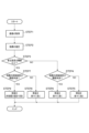
- FIG. 1 shows a vehicle equipped with a light distribution control system according to an embodiment.
- 2 illustrates an example of a functional configuration of the light distribution control system of FIG. 1 .
- 3 illustrates a spatial light modulator included in the illumination device of FIG. 2;
- 3 illustrates a light distribution pattern formed by the lighting device of FIG. 2 .
- 3 illustrates an example of an image captured by the imaging device of FIG. 2 .
- 3 illustrates an example of a process executed by the image processing device of FIG. 2 .
- 3 illustrates a flow of processing executed by the light distribution control system of FIG. 2 .
- 8 illustrates an example of an operation realized by the processing of FIG. 7 . 8 illustrates an example of an operation realized by the processing of FIG. 7 . 8 illustrates another example of the operation realized by the processing of FIG.
- FIG. 7 . 8 illustrates another example of the operation realized by the processing of FIG. 7 . 8 illustrates another example of the operation realized by the processing of FIG. 7 . 8 illustrates another example of the operation realized by the processing of FIG. 7 . 8 illustrates another example of the operation realized by the processing of FIG. 7 . 8 illustrates another example of the operation realized by the processing of FIG. 7 . 8 illustrates another example of the operation realized by the processing of FIG. 7 . 8 illustrates another example of the operation realized by the processing of FIG. 7 . 8 illustrates another example of the operation realized by the processing of FIG. 7 .
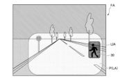
- FIG. 1 illustrates an example of the appearance of a vehicle 20 on which a light distribution control system 10 according to an embodiment is mounted.
- the vehicle 20 is an example of a moving body.
- FIG. 2 illustrates an example of the functional configuration of the light distribution control system 10.
- the light distribution control system 10 includes an imaging device 11.
- the imaging device 11 is disposed, for example, on the upper part of the windshield of the vehicle 20.
- the imaging device 11 is configured to obtain an image that captures at least an area FA located in front of the vehicle 20, and to output an image signal IS corresponding to the image.
- the shape of the area FA shown in FIG. 1 is merely an example.
- the image signal IS may be an analog signal or a digital signal depending on the specifications of the imaging device 11.
- the light distribution control system 10 includes a left lighting device 12L and a right lighting device 12R.
- the left lighting device 12L is mounted on the left front part of the vehicle 20.
- the left lighting device 12L is mounted so as to distribute light to a left illuminated area LAL located at least in front of the vehicle 20.
- the right lighting device 12R is mounted on the right front part of the vehicle 20.
- the right lighting device 12R is mounted so as to distribute light to a right illuminated area LAR located at least in front of the vehicle 20.
- the shapes of the left illuminated area LAL and the right illuminated area LAR shown in FIG. 1 are merely examples.
- the left lighting device 12L and the right lighting device 12R will be collectively referred to as the "lighting device 12" as necessary.
- the left illuminated area LAL and the right illuminated area LAR will be collectively referred to as the "illuminated area LA” as necessary.
- the lighting device 12 includes at least headlights. If light can be distributed to the specified illuminated area LA, the lighting device 12 may include sidelights, fog lights, etc. in addition to the headlights.
- FIG. 3 illustrates a spatial light modulator 121 as an example of a light source used in the illumination device 12.
- the spatial light modulator 121 includes a plurality of light sources 121a.
- the plurality of light sources 121a are arranged in a matrix.
- Each light source 121a is realized by a semiconductor light-emitting element.
- the luminous intensity of the illumination light emitted from each light source 121a can be controlled independently from the other light sources 121a.
- Figure 4 illustrates an example of a light distribution pattern P formed in front of the vehicle 20 by the spatial light modulator 121.
- Symbol H represents a horizontal reference line in the light distribution optical system.
- Symbol V represents a vertical reference line in the light distribution optical system. The horizontal reference line and the vertical reference line are perpendicular to each other. The intersection of the horizontal reference line and the vertical reference line corresponds to the optical axis in the light distribution optical system.
- the light distribution pattern P includes multiple sub-areas SA.
- Each sub-area SA corresponds to one of the multiple light sources 121a provided in the spatial light modulator 121.
- the shape of the light distribution pattern P illustrated in FIG. 4 corresponds to a state in which all the light sources 121a are turned on.
- the light distribution control system 10 includes an image processing device 13.
- the image processing device 13 may be provided as part of the imaging device 11, or may be disposed at an appropriate position in the vehicle 20 independently of the imaging device 11.
- the image processing device 13 is configured to perform specific image processing on the image captured by the imaging device 11.
- the image processing device 13 includes an input interface 131.
- the input interface 131 is configured as a hardware interface that receives the image signal IS output from the imaging device 11. If the image signal IS is an analog signal, the input interface 131 includes an appropriate conversion circuit including an A/D converter.
- the image processing device 13 includes a processor 132. Details of the image processing performed by the processor 132 will be described with reference to Figures 5 and 6.
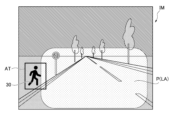
- Figure 5 illustrates an example of an image IM captured by the imaging device 11.
- the image IM reflects at least an area located in front of the vehicle 20.
- the processor 132 is configured to identify an attention area AT in the image IM in which an object estimated to be a predetermined target is reflected, based on an image signal IS corresponding to the image IM.
- Examples of the predetermined target include a vehicle, a person, an animal, a traffic sign, etc.
- an attention area AT in which a person 30 is reflected in the image IM and an attention area AT in which a traffic sign 40 is reflected are identified.
- the processor 132 is configured to acquire recognition accuracy information RL corresponding to a recognition accuracy indicating the likelihood that an object included in the attention area AT is a specified target.
- the recognition accuracy may be determined by a rule-based method or may be inferred by an inference model created through deep learning.
- the term "attention level of a target object" used in this specification means an index indicating the degree of need to alert the driver of the vehicle 20.
- the attention level of the person 30 is higher than that of the traffic sign 40.
- the attention level is determined based on the type of target object, the position of the target object, the speed of the target object, the possibility of the vehicle 20 colliding with the target object if it continues traveling in the current direction, the time until collision with the target object if the vehicle 20 continues traveling in the current direction, and the like.
- the attention level may be determined by a rule-based method or may be inferred by an inference model created through deep learning.
- the image processing device 13 includes an output interface 133 configured as a hardware interface.
- the processor 132 is configured to output the recognition accuracy information RL and the attention level information CA from the output interface 133 in association with the position information of the attention area AT.
- the light distribution control system 10 includes a light distribution processing device 14.
- the light distribution processing device 14 is configured to cause the lighting device 12 to change the light distribution to the illuminated area LA based on the recognition accuracy information RL and the attention level information CA.
- the light distribution processing device 14 may be provided as part of the lighting device 12, or may be disposed at an appropriate position in the vehicle 20 independently of the lighting device 12.
- the light distribution control system 10 includes a control device 15.
- the control device 15 is a general-purpose device that is placed at an appropriate position in the vehicle 20 and is responsible for at least some of the various processes executed in the vehicle 20.
- the control device 15 is equipped with an input interface 151.
- the input interface 151 is connected to the output interface 133 of the image processing device 13 via a communication network installed in the vehicle 20.
- the input interface 151 is configured as a hardware interface that accepts the recognition accuracy information RL and the attention level information CA output from the output interface 133.
- the control device 15 includes a processor 152 and an output interface 153.
- the processor 152 is configured to output, from the output interface 153, a vehicle control signal VC that causes the vehicle 20 to perform an appropriate corresponding action according to a specific target identified by the image processing device 13. Examples of the corresponding action include notifying the driver, warning the target, decelerating, changing course, etc.
- the vehicle control signal VC is transmitted to an appropriate device mounted on the vehicle 20 depending on the corresponding action to be performed.
- the process of changing the light distribution of the lighting device 12 is also an example of a corresponding action.
- the processor 152 is configured to output the recognition accuracy information RL and the attention level information CA received by the input interface 151 from the output interface 153.
- the light distribution processing device 14 is equipped with an input interface 141.
- the input interface 141 is connected to the output interface 153 of the control device 15 via a communication network installed in the vehicle 20.
- the input interface 141 is configured as a hardware interface that accepts the recognition accuracy information RL and the attention level information CA output from the output interface 153.
- the light distribution processing device 14 includes a processor 142 and an output interface 143.
- the processor 142 is configured to execute processing described below based on the recognition accuracy information RL and attention level information CA received by the input interface 141, and to output a light distribution control signal LC that controls the light distribution operation of the lighting device 12 from the output interface 143.
- the light distribution control signal LC may be an analog signal or a digital signal depending on the specifications of the lighting device 12.
- the output interface 143 includes an appropriate conversion circuit including a D/A converter.
- FIG. 7 illustrates an example of the process flow executed in the light distribution control system configured as described above.
- the imaging device 11 captures an image IM that includes at least the area FA located in front of the vehicle 20 (STEP 1).
- the image processing device 13 identifies an attention area AT including an object that is estimated to be a specified target and is reflected in the image IM (STEP 2).
- the image processing device 13 outputs recognition accuracy information RL corresponding to the recognition accuracy indicating the likelihood that the object is the specified target, and attention level information CA corresponding to the attention level of the target, in association with the position of the attention area AT.
- the attention level information CA and recognition accuracy information RL output by the image processing device 13 are received by the light distribution processing device 14 via the control device 15.
- the processor 142 of the light distribution processing device 14 determines whether the attention level corresponding to the attention level information CA is equal to or greater than a threshold value (STEP 3).
- the processor 142 determines whether the recognition accuracy corresponding to the recognition accuracy information RL is less than the threshold (STEP 4).
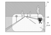
- the processor 142 If it is determined that the recognition accuracy is equal to or greater than the threshold (NO in STEP 4), the processor 142 outputs a light distribution control signal LC from the output interface 143 to cause the lighting device 12 to change the light distribution so that the illuminance of the area corresponding to the attention area AT in the illuminated area LA (i.e., the area where the object being estimated is located) gradually decreases (STEP 5).
- the processor 142 causes the lighting device 12 to change the light distribution pattern P so that the illuminance at the position corresponding to the attention area AT in the illuminated area LA is reduced.
- the processor 142 stores in advance the correspondence between positions in the image IM and positions in the illuminated area LA. Since the attention level information CA and recognition accuracy information RL provided from the image processing device 13 are associated with the position of the attention area AT identified in the image IM, the position in the illuminated area LA corresponding to the position of the attention area AT can be identified.
- the processor 142 gradually reduces the luminance of the illumination light emitted from at least one light source 121a associated with the position of the illuminated area LA in the spatial light modulator 121.
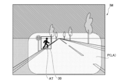
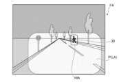
- a relatively low illuminance area LIA is formed in each of the left illuminated area LAL and the right illuminated area LAR, as illustrated in FIG. 1.
- a relatively low illuminance area LIA is formed in the light distribution pattern P, as illustrated in FIG. 9.
- the processor 142 controls the operation of the lighting device 12 to gradually change the illuminance at a position in the illuminated area LA that corresponds to the area of interest AT.
- the expression "gradually changing (lowering/increasing) the illuminance” used in this specification means changing (lowering/increasing) the illuminance of the target area at a gradual speed that the driver of the vehicle 20 cannot notice with normal attention.
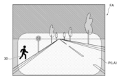
- the processor 142 If it is determined that the level of attention is less than the threshold (NO in STEP 3 of FIG. 7) and the recognition accuracy is less than the threshold (YES in STEP 4), the processor 142 outputs a light distribution control signal LC from the output interface 143 to cause the lighting device 12 to change the light distribution so that the illuminance of the area corresponding to the attention area AT in the illuminated area LA gradually increases (STEP 6).
- the processor 142 causes the lighting device 12 to change the light distribution pattern P so that the illuminance of the position corresponding to the attention area AT in the illuminated area LA is increased.
- the processor 142 identifies a position in the illuminated area LA that corresponds to the position of the attention area AT in the image IM associated with the attention level information CA and recognition accuracy information RL provided from the image processing device 13, based on the correspondence between the positions in the image IM stored in advance and the positions in the illuminated area LA, and gradually increases the luminance of the illumination light emitted from at least one light source 121a associated with the position of the illuminated area LA in the spatial light modulator 121.
- a relatively high illuminance area HIA is formed in the light distribution pattern P.
- the fact that the level of attention required for a target recognized in front of the vehicle 20 is below a threshold value means that there is relatively little urgency in the vehicle 20 taking action in response to the presence of that target.
- the fact that the recognition accuracy of the target is equal to or greater than a threshold value means that there is room to reduce the illuminance of the area in which the target is located. By gradually reducing the illuminance of that area under such circumstances, not only can it be prevented from occurring in a situation in which the recognition accuracy of the target cannot be maintained due to a rapid decrease in illuminance, but it can also reduce the attention of the driver of the vehicle 20 that may be caused by a change in light distribution. In addition, not only can it reduce the power consumption of the lighting device 12, but it can also reduce the occurrence of glare that may be caused to the target.
- the fact that the recognition accuracy of the target is below the threshold means that the area in which the target is located is insufficiently illuminated.
- the processor 142 determines whether the recognition accuracy corresponding to the recognition accuracy information RL is less than the threshold (STEP 7).
- the processor 142 If it is determined that the recognition accuracy is equal to or greater than the threshold (NO in STEP 7), the processor 142 outputs a light distribution control signal LC from the output interface 143 to cause the lighting device 12 to change the light distribution so that the illuminance of the area corresponding to the attention area AT in the illuminated area LA gradually decreases (STEP 8).
- the processor 142 causes the lighting device 12 to change the light distribution pattern P so that the illuminance of the position corresponding to the attention area AT in the illuminated area LA is reduced. Specifically, the processor 142 identifies a position in the illuminated area LA that corresponds to the position of the attention area AT in the image IM associated with the attention level information CA and recognition accuracy information RL provided from the image processing device 13, based on the correspondence between the positions in the image IM stored in advance and the positions in the illuminated area LA, and gradually reduces the luminance of the illumination light emitted from at least one light source 121a associated with the position of the illuminated area LA in the spatial light modulator 121. As a result, an area LIA of relatively low illuminance is formed in the light distribution pattern P.
- the fact that the degree of attention required for a target recognized in front of the vehicle 20 is equal to or greater than a threshold value means that there is a relatively high urgency in the execution of a corresponding action to be taken by the vehicle 20 in consideration of the presence of the target.
- the fact that the recognition accuracy of the target is equal to or greater than a threshold value means that there is room to reduce the illuminance of the area in which the target is located.
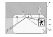
- the processor 142 If it is determined that the level of attention is equal to or greater than the threshold (YES in STEP 3 of FIG. 7) and the recognition accuracy is determined to be less than the threshold (YES in STEP 7), the processor 142 outputs a light distribution control signal LC from the output interface 143 to cause the lighting device 12 to change the light distribution so that the illuminance of the area corresponding to the attention area AT in the illuminated area LA increases to the maximum allowable value (STEP 9).
- the increase in illuminance can be done in at least one stage.
- the processor 142 changes the light distribution pattern P of the lighting device 12 so that the illuminance at the position corresponding to the attention area AT in the illuminated area LA increases to the maximum allowable value. Specifically, the processor 142 identifies a position in the illuminated area LA that corresponds to the position of the attention area AT in the image IM associated with the attention level information CA and the recognition accuracy information RL provided from the image processing device 13, based on the correspondence between the positions in the image IM stored in advance and the positions in the illuminated area LA, and turns on at least one light source 121a associated with the position of the illuminated area LA in the spatial light modulator 121 so that the illuminance of the illuminated area LA becomes the maximum allowable value.
- the light distribution pattern P may be moved to change the light distribution so that the person 30 is illuminated.
- the light distribution may be changed so that the person 30 is illuminated by turning on a lamp included in the lighting device 12 separate from the lamp that forms the light distribution pattern P.
- the fact that the attention level of a target recognized in front of vehicle 20 is equal to or greater than a threshold value means that there is a relatively high urgency in vehicle 20 taking action in response to the presence of that target.
- the fact that the recognition accuracy of the target is less than the threshold value means that there is insufficient lighting in the area where the target is located. In such a situation, it is given priority to increasing the recognition accuracy of the target as quickly as possible and to calling attention to the target by using light distribution, rather than suppressing the driver of vehicle 20 from being drawn to the light distribution by a change in the light distribution.
- the processor 142 determines that the recognition accuracy of the target is equal to or greater than the threshold (NO in STEP 4 or STEP 7 in FIG. 7), the light distribution may be changed so that the illuminance of the area corresponding to the upper portion of the attention area AT decreases before the area corresponding to the lower portion, as illustrated in FIG. 16 and FIG. 17.
- the illuminance of the area where the person's head is located is preferentially reduced.
- the illuminance is uniformly reduced from the top of the attention area AT, processing such as identifying the person's head is not required to achieve the aforementioned effect, and an increase in the processing load on the processor 142 can be suppressed.
- the light distribution pattern P is formed by overlapping the illumination light emitted from the left lighting device 12L and the illumination light emitted from the right lighting device 12R, so the illuminance distribution differs in the left and right directions of the illuminated area.
- the illuminance of the center of the light distribution pattern P in the left and right directions is higher than the illuminance of the left and right ends of the light distribution pattern P.
- the illuminance of the light distribution pattern P decreases the farther away it is from the vehicle 20. Note that differences in illuminance distribution are not shown in the light distribution patterns P illustrated in FIGS. 5, 6, and 8 to 15.
- the value of the illuminance after the change is kept constant.
- the amount of change in illuminance caused by the process of changing the light distribution differs depending on the left-right position of the illuminated area LA and the distance from the vehicle 20 to the target object that is subject to the light distribution change.
- the processor 142 of the light distribution processing device 14 can determine the distance to a target object that requires attention, based on information relating to the position of the attention area AT associated with the attention level information CA and the recognition accuracy information RL received by the input interface 141.
- the processor 142 can be configured to stop the process of gradually decreasing the illuminance at the position corresponding to the attention area AT in the illuminated area LA when it is determined that the distance is less than a threshold value.
- the fact that the distance to the target of interest is less than the threshold value means that there is an increased urgency in the vehicle 20 taking action in response to the presence of the target.
- the processor 132 of the image processing device 13, the processor 142 of the light distribution processing device 14, and the processor 152 of the control device 15, each of which has the various functions described above, can be realized by a general-purpose microprocessor that operates in cooperation with a general-purpose memory.
- general-purpose microprocessors include a CPU, an MPU, and a GPU.
- general-purpose memories include a ROM and a RAM.
- a computer program that realizes the function can be stored in the ROM.
- the general-purpose microprocessor specifies at least a part of the computer program stored in the ROM and deploys it on the RAM, and works with the RAM to execute the above-mentioned processing.
- the computer program can be pre-installed in the general-purpose memory, or can be downloaded from an external server device via a communication network and then installed in the general-purpose memory.
- the processor 132 of the image processing device 13, the processor 142 of the light distribution processing device 14, and the processor 152 of the control device 15, each of which has the various functions described above, may be realized by a dedicated integrated circuit such as a microcontroller, ASIC, or FPGA capable of executing a computer program that realizes the function.
- the computer program is pre-installed in a memory element included in the dedicated integrated circuit.
- the processor 132 of the image processing device 13, the processor 142 of the light distribution processing device 14, and the processor 152 of the control device 15 may each be realized by a combination of a general-purpose microprocessor and a dedicated integrated circuit.
- the processor 142 of the light distribution processing device 14 can be configured to execute the process flow illustrated in FIG. 7 only when it is determined that the level of caution is equal to or greater than the threshold (YES in STEP 3).
- the processor 142 of the light distribution processing device 14 may be configured to execute only the process flow illustrated in FIG. 7 when it is determined that the level of attention is below the threshold (NO in STEP 3).
- the process (STEP 6) of gradually increasing the illuminance which is executed when it is determined that the recognition accuracy of the attention area AT is below the threshold (YES in STEP 4), may be replaced with a process (STEP 9) of increasing the illuminance in at least one step up to the maximum allowable value.
- the spatial light modulator 121 included in the illumination device 12 can be replaced with a scanning device including an optical deflector that deflects the light emitted from the light source.
- the optical deflector can be constructed using a movable mirror such as a MEMS (Micro Electro Mechanical Systems) mirror or a galvanometer mirror.
- the shape of the vehicle 20 illustrated in FIG. 1 is merely an example.
- the shape and number of wheels of the vehicle 20 on which the light distribution control system 10 is mounted can be determined as appropriate.
- the moving object on which the light distribution control system 10 is mounted is not limited to the vehicle 20.
- Other examples of moving objects include tramways, etc.
Landscapes
- Engineering & Computer Science (AREA)
- Multimedia (AREA)
- Signal Processing (AREA)
- Physics & Mathematics (AREA)
- General Physics & Mathematics (AREA)
- Mechanical Engineering (AREA)
- Lighting Device Outwards From Vehicle And Optical Signal (AREA)
Abstract
L'invention concerne un dispositif d'imagerie (11) qui acquiert une image dans laquelle est réfléchie une région située au moins devant un corps mobile. Un dispositif d'éclairage (12) distribue de la lumière à une région à éclairer positionnée au moins devant le corps mobile. Un dispositif de traitement d'image (13) délivre des informations de précision de reconnaissance (RL) indiquant la probabilité qu'un objet réfléchi dans l'image soit une cible prédéterminée, et des informations de degré de prudence nécessaire (CA) correspondant à un degré de prudence nécessaire pour la cible. Un dispositif de traitement de distribution de lumière (14) amène le dispositif d'éclairage (12) à modifier la distribution de lumière sur la base des informations de précision de reconnaissance (RL) et des informations de degré de prudence nécessaire (CA). Lorsque le degré de prudence nécessaire est inférieur à une valeur de seuil, le dispositif de traitement de distribution de lumière (14) modifie progressivement l'éclairage de la région où la cible est positionnée dans la région à éclairer conformément à la précision de reconnaissance.
Applications Claiming Priority (2)
| Application Number | Priority Date | Filing Date | Title |
|---|---|---|---|
| JP2023181190 | 2023-10-20 | ||
| JP2023-181190 | 2023-10-20 |
Publications (1)
| Publication Number | Publication Date |
|---|---|
| WO2025084251A1 true WO2025084251A1 (fr) | 2025-04-24 |
Family
ID=95447898
Family Applications (1)
| Application Number | Title | Priority Date | Filing Date |
|---|---|---|---|
| PCT/JP2024/036513 Pending WO2025084251A1 (fr) | 2023-10-20 | 2024-10-11 | Système de commande de distribution de lumière, et procédé de commande de distribution de lumière |
Country Status (1)
| Country | Link |
|---|---|
| WO (1) | WO2025084251A1 (fr) |
Citations (5)
| Publication number | Priority date | Publication date | Assignee | Title |
|---|---|---|---|---|
| JP2019077204A (ja) * | 2017-10-19 | 2019-05-23 | 株式会社小糸製作所 | 車両用灯具システム、車両用灯具の制御装置および車両用灯具の制御方法 |
| WO2019131055A1 (fr) * | 2017-12-27 | 2019-07-04 | 株式会社小糸製作所 | Système de phare de véhicule, dispositif de commande de phare de véhicule et procédé de commande de phare de véhicule |
| WO2021010485A1 (fr) * | 2019-07-18 | 2021-01-21 | 株式会社小糸製作所 | Système d'éclairage de véhicule, dispositif de commande d'éclairage de véhicule et procédé de commande d'éclairage de véhicule |
| WO2021112093A1 (fr) * | 2019-12-04 | 2021-06-10 | 株式会社小糸製作所 | Système de lampe de véhicule, dispositif de commande de distribution de lumière et procédé de commande de distribution de lumière |
| WO2022270413A1 (fr) * | 2021-06-21 | 2022-12-29 | 株式会社小糸製作所 | Dispositif de commande de distribution de lumière, système de lumière de véhicule et procédé de commande de distribution de lumière |
-
2024
- 2024-10-11 WO PCT/JP2024/036513 patent/WO2025084251A1/fr active Pending
Patent Citations (5)
| Publication number | Priority date | Publication date | Assignee | Title |
|---|---|---|---|---|
| JP2019077204A (ja) * | 2017-10-19 | 2019-05-23 | 株式会社小糸製作所 | 車両用灯具システム、車両用灯具の制御装置および車両用灯具の制御方法 |
| WO2019131055A1 (fr) * | 2017-12-27 | 2019-07-04 | 株式会社小糸製作所 | Système de phare de véhicule, dispositif de commande de phare de véhicule et procédé de commande de phare de véhicule |
| WO2021010485A1 (fr) * | 2019-07-18 | 2021-01-21 | 株式会社小糸製作所 | Système d'éclairage de véhicule, dispositif de commande d'éclairage de véhicule et procédé de commande d'éclairage de véhicule |
| WO2021112093A1 (fr) * | 2019-12-04 | 2021-06-10 | 株式会社小糸製作所 | Système de lampe de véhicule, dispositif de commande de distribution de lumière et procédé de commande de distribution de lumière |
| WO2022270413A1 (fr) * | 2021-06-21 | 2022-12-29 | 株式会社小糸製作所 | Dispositif de commande de distribution de lumière, système de lumière de véhicule et procédé de commande de distribution de lumière |
Similar Documents
| Publication | Publication Date | Title |
|---|---|---|
| JP7287979B2 (ja) | 灯具システムおよび車両用灯具 | |
| US9481292B2 (en) | Method and control unit for influencing a lighting scene ahead of a vehicle | |
| CN105291955B (zh) | 根据车辆的环境定向车辆的大灯的照明区域的方法和设备 | |
| JP6372376B2 (ja) | 前照灯制御装置 | |
| JP5249612B2 (ja) | 車両用前照灯装置 | |
| JP7436696B2 (ja) | 自動車の周囲モニタリングシステム | |
| EP3882076A1 (fr) | Système de lampe pour véhicule | |
| JP7034718B2 (ja) | 車両用表示装置 | |
| EP3858668B1 (fr) | Système de lampe | |
| CN107128240A (zh) | 车辆、车辆的照明系统及其控制方法 | |
| JP2018058542A (ja) | 車両用照明装置 | |
| JPWO2020035713A1 (ja) | ヘッドランプ制御方法及びヘッドランプ制御装置 | |
| WO2025084251A1 (fr) | Système de commande de distribution de lumière, et procédé de commande de distribution de lumière | |
| JP7137414B2 (ja) | 車両用灯具 | |
| WO2025084250A1 (fr) | Système de commande de distribution de lumière, et procédé de commande de distribution de lumière | |
| JP7366070B2 (ja) | 車両用灯具の制御装置、車両用灯具システムおよび車両用灯具の制御方法 | |
| JP2017177941A (ja) | 車両の配光制御装置 | |
| US11465552B2 (en) | Method for obtaining an image of an object to be classified and associated system | |
| US20240083344A1 (en) | Vehicle lighting device | |
| CN110382296B (zh) | 照明装置 | |
| CN217843721U (zh) | 车用照明装置 | |
| US10920951B2 (en) | Headlight for a motor vehicle | |
| JP2023138412A (ja) | 適応型自動車前照灯の制御方法 | |
| JP6162012B2 (ja) | 車両用前照灯の点灯制御装置、車両用前照灯システム | |
| CN111051132A (zh) | 用于操控车辆的照明单元的至少一个主前照灯的方法、照明单元、计算机程序产品以及计算机可读介质 |
Legal Events
| Date | Code | Title | Description |
|---|---|---|---|
| 121 | Ep: the epo has been informed by wipo that ep was designated in this application |
Ref document number: 24879676 Country of ref document: EP Kind code of ref document: A1 |