WO2025089331A1 - Distributeur de type à pompe - Google Patents
Distributeur de type à pompe Download PDFInfo
- Publication number
- WO2025089331A1 WO2025089331A1 PCT/JP2024/037888 JP2024037888W WO2025089331A1 WO 2025089331 A1 WO2025089331 A1 WO 2025089331A1 JP 2024037888 W JP2024037888 W JP 2024037888W WO 2025089331 A1 WO2025089331 A1 WO 2025089331A1
- Authority
- WO
- WIPO (PCT)
- Prior art keywords
- elastic piece
- head
- cap
- pump
- peripheral surface
- Prior art date
- Legal status (The legal status is an assumption and is not a legal conclusion. Google has not performed a legal analysis and makes no representation as to the accuracy of the status listed.)
- Pending
Links
Images





Classifications
-
- B—PERFORMING OPERATIONS; TRANSPORTING
- B05—SPRAYING OR ATOMISING IN GENERAL; APPLYING FLUENT MATERIALS TO SURFACES, IN GENERAL
- B05B—SPRAYING APPARATUS; ATOMISING APPARATUS; NOZZLES
- B05B11/00—Single-unit hand-held apparatus in which flow of contents is produced by the muscular force of the operator at the moment of use
- B05B11/01—Single-unit hand-held apparatus in which flow of contents is produced by the muscular force of the operator at the moment of use characterised by the means producing the flow
- B05B11/10—Pump arrangements for transferring the contents from the container to a pump chamber by a sucking effect and forcing the contents out through the dispensing nozzle
- B05B11/1042—Components or details
- B05B11/1073—Springs
- B05B11/1077—Springs characterised by a particular shape or material
-
- B—PERFORMING OPERATIONS; TRANSPORTING
- B05—SPRAYING OR ATOMISING IN GENERAL; APPLYING FLUENT MATERIALS TO SURFACES, IN GENERAL
- B05B—SPRAYING APPARATUS; ATOMISING APPARATUS; NOZZLES
- B05B11/00—Single-unit hand-held apparatus in which flow of contents is produced by the muscular force of the operator at the moment of use
-
- B—PERFORMING OPERATIONS; TRANSPORTING
- B05—SPRAYING OR ATOMISING IN GENERAL; APPLYING FLUENT MATERIALS TO SURFACES, IN GENERAL
- B05B—SPRAYING APPARATUS; ATOMISING APPARATUS; NOZZLES
- B05B11/00—Single-unit hand-held apparatus in which flow of contents is produced by the muscular force of the operator at the moment of use
- B05B11/0005—Components or details
- B05B11/0027—Means for neutralising the actuation of the sprayer ; Means for preventing access to the sprayer actuation means
- B05B11/0032—Manually actuated means located downstream the discharge nozzle for closing or covering it, e.g. shutters
-
- B—PERFORMING OPERATIONS; TRANSPORTING
- B05—SPRAYING OR ATOMISING IN GENERAL; APPLYING FLUENT MATERIALS TO SURFACES, IN GENERAL
- B05B—SPRAYING APPARATUS; ATOMISING APPARATUS; NOZZLES
- B05B11/00—Single-unit hand-held apparatus in which flow of contents is produced by the muscular force of the operator at the moment of use
- B05B11/0005—Components or details
- B05B11/0037—Containers
- B05B11/0039—Containers associated with means for compensating the pressure difference between the ambient pressure and the pressure inside the container, e.g. pressure relief means
- B05B11/0044—Containers associated with means for compensating the pressure difference between the ambient pressure and the pressure inside the container, e.g. pressure relief means compensating underpressure by ingress of atmospheric air into the container, i.e. with venting means
-
- B—PERFORMING OPERATIONS; TRANSPORTING
- B05—SPRAYING OR ATOMISING IN GENERAL; APPLYING FLUENT MATERIALS TO SURFACES, IN GENERAL
- B05B—SPRAYING APPARATUS; ATOMISING APPARATUS; NOZZLES
- B05B11/00—Single-unit hand-held apparatus in which flow of contents is produced by the muscular force of the operator at the moment of use
- B05B11/01—Single-unit hand-held apparatus in which flow of contents is produced by the muscular force of the operator at the moment of use characterised by the means producing the flow
- B05B11/10—Pump arrangements for transferring the contents from the container to a pump chamber by a sucking effect and forcing the contents out through the dispensing nozzle
- B05B11/1001—Piston pumps
- B05B11/1023—Piston pumps having an outlet valve opened by deformation or displacement of the piston relative to its actuating stem
-
- B—PERFORMING OPERATIONS; TRANSPORTING
- B05—SPRAYING OR ATOMISING IN GENERAL; APPLYING FLUENT MATERIALS TO SURFACES, IN GENERAL
- B05B—SPRAYING APPARATUS; ATOMISING APPARATUS; NOZZLES
- B05B11/00—Single-unit hand-held apparatus in which flow of contents is produced by the muscular force of the operator at the moment of use
- B05B11/01—Single-unit hand-held apparatus in which flow of contents is produced by the muscular force of the operator at the moment of use characterised by the means producing the flow
- B05B11/10—Pump arrangements for transferring the contents from the container to a pump chamber by a sucking effect and forcing the contents out through the dispensing nozzle
- B05B11/1042—Components or details
- B05B11/1043—Sealing or attachment arrangements between pump and container
- B05B11/1046—Sealing or attachment arrangements between pump and container the pump chamber being arranged substantially coaxially to the neck of the container
- B05B11/1047—Sealing or attachment arrangements between pump and container the pump chamber being arranged substantially coaxially to the neck of the container the pump being preassembled as an independent unit before being mounted on the container
-
- B—PERFORMING OPERATIONS; TRANSPORTING
- B05—SPRAYING OR ATOMISING IN GENERAL; APPLYING FLUENT MATERIALS TO SURFACES, IN GENERAL
- B05B—SPRAYING APPARATUS; ATOMISING APPARATUS; NOZZLES
- B05B11/00—Single-unit hand-held apparatus in which flow of contents is produced by the muscular force of the operator at the moment of use
- B05B11/01—Single-unit hand-held apparatus in which flow of contents is produced by the muscular force of the operator at the moment of use characterised by the means producing the flow
- B05B11/10—Pump arrangements for transferring the contents from the container to a pump chamber by a sucking effect and forcing the contents out through the dispensing nozzle
- B05B11/1042—Components or details
- B05B11/1066—Pump inlet valves
- B05B11/1067—Pump inlet valves actuated by pressure
- B05B11/1069—Pump inlet valves actuated by pressure the valve being made of a resiliently deformable material or being urged in a closed position by a spring
-
- F—MECHANICAL ENGINEERING; LIGHTING; HEATING; WEAPONS; BLASTING
- F04—POSITIVE - DISPLACEMENT MACHINES FOR LIQUIDS; PUMPS FOR LIQUIDS OR ELASTIC FLUIDS
- F04B—POSITIVE-DISPLACEMENT MACHINES FOR LIQUIDS; PUMPS
- F04B9/00—Piston machines or pumps characterised by the driving or driven means to or from their working members
- F04B9/14—Pumps characterised by muscle-power operation
Definitions
- the present invention relates to a pump-type dispenser.
- a known pump-type dispenser includes a cap that is attached to the mouth of a container, a pump that is held at the mouth by the cap and is driven by the back and forth movement of a stem, and a head that is connected to the stem; the liquid contents in the container are dispensed from the head's outlet by moving the head towards the cap (see, for example, Patent Document 1).
- a coil spring is provided to return the head, which has been moved toward the cap, to its initial position.
- the coil spring is made of metal. For this reason, when it is discarded after use, it cannot be recycled as a resin product in this state. Furthermore, in general, in this type of pump dispenser, the components are firmly fixed together, for example by fitting, to prevent them from coming loose during normal use. Therefore, it takes a lot of effort to disassemble the pump dispenser and separate the coil spring from the other components.
- the present invention aims to solve these problems by proposing a pump-type dispenser that is capable of discharging the liquid contents in the same way as conventional dispensers, and that also has excellent recyclability.
- the present invention relates to a pump-type dispenser comprising a cap attached to the mouth of a container that contains a liquid content, a pump that is held at the mouth by the cap and is driven by the back and forth movement of a stem, and a head that has a discharge port for discharging the liquid content to the outside and is connected to the stem, the head being moved toward the cap to discharge the liquid content from the discharge port,
- An extension portion is provided on one of the head and the cap, the extension portion extending toward the other of the head and the cap, an inwardly collapsing elastic piece is provided on the other of the head and the cap, the extension contacting an outer circumferential surface and bending in a direction approaching a central axis of the stem when the head is advanced toward the cap;
- the outer peripheral surface of the inward-inclined elastic piece is inclined away from the inner peripheral surface of the inward-inclined elastic piece with respect to a reference line extending parallel to the central axis of the stem from the base portion of the inward-
- the angle at which the outer peripheral surface is inclined with respect to the reference line is greater than 0° and not greater than 3°.
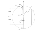
- the outer peripheral surface has an inclined surface that starts from an inflection point located within 1 to 3 mm rearward along the reference line from the forward movement limit contact point before the inward-inclined elastic piece is deflected by the extension portion, and that inclines in a direction approaching the inner peripheral surface as it moves from the inflection point toward the base portion.
- the angle at which the inclined surface is inclined relative to the outer peripheral surface is greater than or equal to 2° and less than or equal to 5°.
- the present invention also provides a pump-type dispenser comprising: a cap attached to the mouth of a container that contains a liquid content; a pump that is held at the mouth by the cap and is driven by the back and forth movement of a stem; and a head connected to the stem and having a discharge port for discharging the liquid content to the outside, the head being moved toward the cap to discharge the liquid content from the discharge port,
- An extension portion is provided on one of the head and the cap, the extension portion extending toward the other of the head and the cap, an outwardly collapsing elastic piece is provided on the other of the head and the cap, the outwardly collapsing elastic piece being bent in a direction away from the central axis of the stem by contacting an inner circumferential surface of the extension portion when the head is advanced toward the cap;
- the inner surface of the outwardly-inclined elastic piece is also a pump-type discharger inclined in a direction away from the outer surface of the outwardly-inclined elastic piece with respect to a
- the angle at which the inner circumferential surface is inclined relative to the reference line is greater than 0° and not greater than 3°.
- the inner surface has an inclined surface that starts from an inflection point located within 1 to 3 mm rearward along the reference line from the forward limit contact point before the outwardly-inclined elastic piece is deflected by the extension portion, and slopes in a direction approaching the outer surface as it moves from the inflection point toward the base portion.
- the angle at which the inclined surface is inclined relative to the inner circumferential surface is preferably greater than or equal to 2° and less than or equal to 5°.
- the extension comes into contact with the outer peripheral surface of the inwardly inclined elastic piece, causing the inwardly inclined elastic piece to bend in a direction approaching the central axis of the stem, so that the head can be returned to its initial position when the bent inwardly inclined elastic piece returns to its original position.
- the outer peripheral surface of the inwardly inclined elastic piece is usually formed in a tilted manner (so as to create a draft angle with respect to the mold) with respect to a reference line (a reference line extending parallel to the central axis of the stem) that starts from the root and extends parallel to the direction in which the mold moves during mold release, taking into consideration releasability from the mold.
- a reference line a reference line extending parallel to the central axis of the stem
- the outer peripheral surface of the inwardly inclined elastic piece in the present invention is inclined with respect to this reference line in a direction that moves away from the inner peripheral surface of the inwardly inclined elastic piece as it moves from the root to the tip. That is, compared to an inwardly inclined elastic piece having an outer peripheral surface inclined to create a draft gradient, the inwardly inclined elastic piece of the present invention has a smaller angle of inclination toward the center axis of the stem as the head is moved toward the cap, so the load on the inwardly inclined elastic piece is smaller.
- a resilient piece capable of bending such as an inwardly inclined elastic piece is repeatedly bent with a relatively large load, it may become sagging and its restorability may decrease.
- the inwardly inclined elastic piece of the present invention has a smaller load when bending than an inwardly inclined elastic piece having an outer peripheral surface inclined to create a draft gradient, so the effect of sagging can be suppressed.
- the load on the inwardly inclined elastic piece when bending is small, excessive force is not required to press the head.
- the inwardly inclined elastic piece is used instead of a metal coil spring, there is no need to separate metal parts when disposing of the pump-type dispenser as in the conventional pump-type dispenser, and it can be reused as a resin product, so it is highly recyclable.
- the extension contacts the inner peripheral surface of the outwardly inclined elastic piece, and this inner peripheral surface is inclined away from the outer peripheral surface of the outwardly inclined elastic piece as it moves from the base portion to the tip portion, relative to a reference line that extends parallel to the central axis of the stem from the base portion.
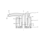
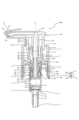
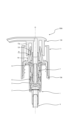
- FIG. 2 is a vertical cross-sectional side view of the first embodiment of the pump-type dispenser according to the present invention, showing a state before an inwardly inclined elastic piece is bent.
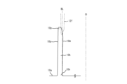
- FIG. 2 is a partial enlarged view of the inwardly collapsing elastic piece shown in FIG. 1 .
- FIG. 10 is a partially enlarged view of an outwardly collapsing elastic piece according to another embodiment of the pump-type dispenser of the present invention.
- 2 is a vertical cross-sectional view seen from the side, showing a state in which the head is pressed from the state shown in FIG. 1 and an inwardly collapsing elastic piece is bent.
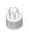
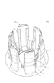
- FIG. 2 is a perspective view of the cap shown in FIG. 1 .
- FIG. 11 is a vertical cross-sectional side view of a second embodiment of a pump-type dispenser according to the present invention, showing a state before an inwardly inclined elastic piece is bent.
- FIG. 6 is a partial enlarged view of the inwardly collapsing elastic piece shown in FIG. 5 .
- FIG. 6B is a partially enlarged view of the periphery of the inclined surface shown in FIG. 6A.
- FIG. 10 is a partially enlarged view of an outwardly collapsing elastic piece according to another embodiment of the pump-type dispenser of the present invention.
- FIG. 7B is a partially enlarged view of the periphery of the inclined surface shown in FIG. 7A.
- FIG. 6 is a vertical cross-sectional view seen from the side, showing a state in which the head is pressed from the state shown in FIG. 5 and the inwardly collapsing elastic pieces are bent.
- FIG. 6 is a perspective view of the cap shown in FIG. 5 .
- the up-down direction refers to the direction along the illustrated central axis O (the central axis of the stem 7a described below), with the side on which the pipe 4 is located being the “bottom” and the side on which the head 12 is located being the "top.”
- the radial direction refers to the direction perpendicular to the central axis O in a plane perpendicular to the central axis O
- the circumferential direction refers to the direction rotating around the central axis O in this plane.
- the pump-type dispenser 100 of this embodiment is used by attaching it to the mouth of a bottle-shaped container (not shown).
- the liquid content dispensed by the pump-type dispenser 100 is, for example, a cosmetic product (such as a milky lotion or toner), shampoo, body soap, hand soap, facial cleanser, etc.
- the pump-type dispenser 100 is composed of a cylinder 1, a valve member 2, a pipe 4, an internal member 5, a piston 6, a cylindrical member 7, a holder 8, a packing 9, a cap 10, a cover 11, a head 12, and a nozzle cover 13.
- the cylinder 1, the valve member 2, the internal member 5, the piston 6, the cylindrical member 7, and the holder 8 are members that constitute the "pump" in this specification.
- the valve member 2, the piston 6, and the packing 9 are made of elastic soft synthetic resin (e.g., polyethylene (LDPE, HDPE, foamed PE)), and the other members are made of hard synthetic resin (e.g., polypropylene (PP), polybutylene terephthalate (PBT), polyacetal (POM), polyketone (POK) resin, etc.).
- LDPE polyethylene
- HDPE high density polyethylene
- PBT polybutylene terephthalate
- POM polyacetal
- POK polyketone
- Each member that constitutes the pump-type dispenser 100 is basically formed in a shape centered on the central axis O.
- the cylinder 1 has a disk-shaped bottom wall 1a with an upwardly protruding central portion, a cylindrical tube wall 1b that stands up from the outer edge of the bottom wall 1a, and a flange wall 1c that extends radially outward from the upper part of the tube wall 1b.
- a through hole (suction port 1d) is provided in the protruding central portion of the bottom wall 1a.
- a cylindrical retaining tube 1e that surrounds the suction port 1d and extends downward to hold the pipe 4 is provided on the underside of the bottom wall 1a.
- a through hole (vent hole 1f) is provided in the tube wall 1b.
- the valve member 2 comprises a base 2a, a valve body portion 2b that covers the suction port 1d and seats on the upper surface of the bottom wall portion 1a, and an elastically deformable connecting piece 2c that connects the base 2a and the valve body portion 2b.
- the valve member 2 functions as a check valve, and when the pressure inside the cylinder 1 is reduced, the valve body portion 2b that has been closing the suction port 1d moves away from the bottom wall portion 1a, opening the suction port 1d.
- the base 2a is cylindrical with a lid and has an opening (not shown) through which the liquid content passes after passing through the suction port 1d.
- the base 2a is fitted and held against the inner circumferential surface of the cylindrical wall portion 1b, so that the valve member 2 is held within the cylinder 1.
- the pipe 4 is hollow, and its upper end is inserted into the retaining tube 1e and is held in place by it.
- the internal member 5 is disposed inside the cylinder 1 and is a member that moves up and down relative to the cylinder 1.
- the internal member 5 comprises a cylindrical connecting tube 5a and a bottom portion 5b that closes the lower end of the connecting tube 5a and extends radially outward.
- the connecting tube 5a is provided with a hole (communication port 5c) that passes through it, and the top surface of the bottom portion 5b is provided with an annular portion 5d that is located radially outward from the connection portion with the connecting tube 5a.
- the piston 6 is inserted through the connecting tube 5a and positioned above the bottom 5b.
- the piston 6 in this embodiment has a circular base 6a.
- An outer sliding piece 6b extending upward and downward from the base 6a is provided on the outer edge of the base 6a.
- the outer sliding piece 6b slidably and liquid-tightly contacts the inner peripheral surface of the tube wall portion 1b.
- An inner sliding piece 6c extending upward and downward from the base 6a is provided on the inner edge of the base 6a.
- the lower part of the inner sliding piece 6c slidably and liquid-tightly contacts the inner peripheral surface of the annular portion 5d, and the upper part slidably and liquid-tightly contacts the inner peripheral surface of the enlarged diameter portion 7b of the tubular member 7, which will be described later.
- the tubular member 7 is a member that is generally tubular.
- the tubular member 7 has a cylindrical stem 7a and an enlarged diameter portion 7b that is connected to the lower end of the stem 7a and has a larger diameter than the stem 7a.
- the holder 8 has a portion located radially outward of the stem 7a and a portion located radially outward of the enlarged diameter portion 7b, and is equipped with a holder base 8a that is fitted and held against the inner peripheral surface of the cylindrical wall portion 1b.
- a flange 8b extending radially outward is provided at the upper end of the holder base 8a. The holder 8 prevents the internal member 5, piston 6, and cylindrical member 7 from slipping out of the cylinder 1.
- the packing 9 is in the shape of a circular ring plate, and is inserted into and held in the cylindrical wall portion 1b of the cylinder 1.
- the packing 9 is sandwiched between the mouth of the container and the flange wall 1c. This prevents problems such as the contents spilling out of the mouth when the container is turned over, for example.
- the cap 10 has a disk-shaped top wall 10a with a through hole in the center.
- a cylindrical peripheral wall 10b extending downward is provided on the outer edge of the top wall 10a.
- the upper part of the inner peripheral surface of the peripheral wall 10b bulges radially inward to fit and hold the flange wall 1c, thereby holding the cylinder 1 in the cap 10.
- the inner peripheral surface of the cap 10 has a female threaded portion 10c that screws into a male threaded portion provided on the mouth of the container, and the cap 10 can be attached to the container by screwing the male threaded portion and the female threaded portion 10c together.
- the outer peripheral surface of the peripheral wall 10b has a rotation prevention recess 10d extending in the vertical direction, as shown in the partial enlarged view of FIG. 1.
- a plurality of rotation prevention recesses 10d are provided at intervals in the circumferential direction.
- the cap 10 also includes plate-shaped inwardly inclined elastic pieces 10e that extend upward from the upper surface of the top wall 10a and are capable of elastically deforming radially inward.
- the inwardly inclined elastic pieces 10e are formed in an arc shape centered on the central axis O in a plan view, and a total of six of them are provided at equal intervals in the circumferential direction (see FIG. 4).
- the outer peripheral surface 10f of the inwardly inclined elastic piece 10e is inclined in a direction away from the inner peripheral surface 10j of the inwardly inclined elastic piece 10e (diametrically outward) from the lower end (root portion 10g) connected to the top wall 10a to the reference line BL that extends parallel to the central axis O.
- the cap 10 of this embodiment is formed by injection molding using a mold, and this mold is basically composed of an upper mold and a lower mold, one of which moves along the reference line BL relative to the other.
- the outer peripheral surface 10f is inclined in the direction of forcible removal relative to the upper mold.
- the length of the inwardly inclined elastic piece 10e (the length from the upper surface of the top wall 10a to the upper end surface of the inwardly inclined elastic piece 10e) is preferably 10 mm or more and 40 mm or less, so that it can be elastically deformed radially inward and so that the size of the pump-type dispenser 100 does not become excessively large.
- the angle at which the outer peripheral surface 10f is inclined with respect to the reference line BL is preferably greater than 0° and less than 3°. If the angle is within this range, the inwardly inclined elastic piece 10e can be released from the mold even if the inclination is in the direction of forced removal.
- the outer peripheral surface of the tip 10h of the inwardly inclined elastic piece 10e is inclined so that the diameter of the tip 10h decreases as it approaches the upper side, and the inclination angle with respect to the reference line BL at this portion is 10° to 45° (approximately 15° in the present embodiment).
- the inner peripheral surface 10j of the inwardly inclined elastic piece 10e of the present embodiment extends in the direction of the draft gradient that is normally set when the piece is released from the mold, and specifically, it is inclined in the direction approaching the outer peripheral surface 10f (diametrically outward) as it moves from the lower end connected to the top wall 10a to the upper end.
- the inclination angle of the inner peripheral surface 10j with respect to the reference line BL is greater than 0° and less than 3° (approximately 1° in the present embodiment).
- the inner peripheral surface 10j may extend parallel to the reference line BL (the angle between the inner peripheral surface 10j and the reference line BL is 0°), or may be inclined at a larger angle than the normally set draft gradient.
- the cover 11 has a cylindrical cover peripheral wall 11a.
- the cover peripheral wall 11a surrounds the peripheral wall 10b and the inwardly inclined elastic piece 10e.
- the lower end of the cover peripheral wall 11a is provided with a stopper protrusion 11b that protrudes radially inward and engages with the lower end of the peripheral wall 10b.
- the inner peripheral surface of the cover peripheral wall 11a is provided with a rib 11c extending in the vertical direction.
- the lower part of the rib 11c engages with the anti-rotation recess 10d, and the cover 11 is held in the cap 10 without rotating.
- the upper part of the rib 11c protrudes radially inward more than the lower part.
- the lower end surface of the upper part contacts the upper surface of the top wall 10a, and the stopper protrusion 11b engages with the lower end of the peripheral wall 10b as described above, so that the cover 11 is held in the cap 10 without falling off.
- the upper end of the cover peripheral wall 11a is provided with an inward flange 11d that extends radially inward.
- the head 12 is cylindrical and has a tubular portion 12a into which the stem 7a is inserted and held in place.
- the upper portion of the tubular portion 12a is provided with a top portion 12b whose upper surface is shaped so as to be concave downwards and which has a passage inside that leads to the tubular portion 12a.
- the top portion 12b is provided with a nozzle 12c which is cylindrical and extends radially outward and leads to a passage provided inside the top portion 12b.
- the tip of the nozzle 12c is provided with a discharge port 12d through which the content liquid is discharged by the pump type discharger 100.
- the head 12 also has an extension 12e that extends downward from the top 12b and the nozzle 12c.
- the extension 12e is cylindrical with the central axis O as its center.
- the lower end (tip) of the extension 12e is inclined so as to narrow radially inward as it extends generally downward.
- the inwardly inclined elastic piece 10e stands upright in the vertical direction, and the lower end of the extension 12e is illustrated as overlapping with the upper end of the inwardly inclined elastic piece 10e, but in reality, the inwardly inclined elastic piece 10e is slightly inclined radially inward so that this overlap is eliminated, and the head 12 moves to its upper limit (rear limit).
- the nozzle cover 13 has a cover body 13a that surrounds the outer periphery and tip of the nozzle 12c.
- the cover body 13a is provided with a cover retaining portion 13b that is C-shaped in a plan view, and the cover retaining portion 13b is retained by the extension portion 12e by moving laterally from the opening of this C-shaped portion toward the extension portion 12e.
- the tip of the extension 12e contacts the inwardly collapsing elastic piece 10e, and the head 12 is in a raised state (the head 12 is retracted from the cap 10).
- the stem 7a When the head 12 is pressed from above to lower it (the head 12 is advanced toward the cap 10), the stem 7a is pressed down together with the head 12 (the stem 7a moves toward the cap 10 along the central axis O). As the stem 7a is pressed down, the bottom 5b also descends via the connecting tube 5a, and the liquid-tight contact between the annular portion 5d and the lower portion of the inner sliding piece 6c is released. When the head 12 is pressed down further, the piston 6 also descends together with the tubular member 7 and internal member 5, and the inside of the cylinder 1 is pressurized.
- the liquid content in the cylinder 1 passes through the communication port 5c, passes through the connecting tube 5a, the stem 7a, the tubular portion 12a, the passage provided inside the top portion 12b, and the inside of the nozzle 12c, and is discharged from the discharge port 12d to the outside world.
- the container (not shown) communicates with the outside world through the vent 1f. This prevents the pressure inside the container from becoming negative even if the liquid contained in the container decreases, preventing the container from being deformed or crushed.
- the extension 12e moves downward while contacting the outer peripheral surface 10f of the inwardly inclined elastic piece 10e, so that the inwardly inclined elastic piece 10e bends radially inward as shown in Figure 3.
- the outer peripheral surface 10f of the inwardly inclined elastic piece 10e is inclined toward the inner peripheral surface 10j from the base portion 10g toward the tip portion 10h, as in the case of a normal draft slope, the extension 12e and the outer peripheral surface 10f will come into increasingly strong contact as the head 12 is pressed down, and the angle at which the inwardly inclined elastic piece 10e falls will increase.
- the outer peripheral surface 10f of the inwardly inclined elastic piece 10e of this embodiment is inclined away from the inner peripheral surface 10j from the base portion 10g toward the tip portion 10h. That is, in the present embodiment, compared to an inwardly inclined elastic piece 10e with an inclined outer peripheral surface 10f so as to have a normal draft angle, the angle at which the inwardly inclined elastic piece 10e falls becomes smaller as the head 12 is pressed down, and therefore the load on the inwardly inclined elastic piece 10e also becomes smaller, making it possible to suppress the effects of settling when repeatedly flexed. Also, because the load on the inwardly inclined elastic piece 10e when it flexes is smaller, excessive force is not required when pressing the head 12.
- the pump-type dispenser 100 of this embodiment can return the head 12 to its original position after discharging the liquid content without using a metal coil spring, and can be used in the same way as a conventional pump-type dispenser.
- the effect of settling caused by repeated bending of the inwardly collapsing elastic piece 10e can be suppressed, preventing the head 12 from becoming difficult to return to its original position when used continuously.
- the pump-type discharger 100 described above can achieve the same effect by using the outwardly inclined elastic piece 10k and the extension portion 12f shown in FIG. 2B instead of the inwardly inclined elastic piece 10e and the extension portion 12e shown in FIG. 2A.
- the outwardly inclined elastic piece 10k like the inwardly inclined elastic piece 10e, is formed in an arc shape centered on the central axis O in a plan view, and a total of six of them are provided at equal intervals in the circumferential direction.
- the inner peripheral surface 10m of the outwardly inclined elastic piece 10k shown in the figure is inclined in a direction away from the outer peripheral surface 10q of the outwardly inclined elastic piece 10k (diametrically inward) from the lower end (root portion 10n) connected to the top wall 10a to the reference line BL that extends parallel to the central axis O. As it moves from the lower end to the upper end (tip portion 10p), the inner peripheral surface 10m of the outwardly inclined elastic piece 10k is inclined in the direction of forcible removal from the mold that forms it.
- the length of the outwardly inclined elastic piece 10k (the length from the upper surface of the top wall 10a to the upper end surface of the outwardly inclined elastic piece 10k), like the length of the inwardly inclined elastic piece 10e, is preferably 10 mm or more and 40 mm or less, and the angle of inclination of the inner peripheral surface 10m with respect to the reference line BL is preferably greater than 0° and less than 3°.
- the inner circumferential surface of the tip 10p of the outwardly inclined elastic piece 10k is inclined so that the diameter decreases as it approaches the upper part, and the inclination angle with respect to the reference line BL at this part is 10° or more and 45° or less (about 15° in this embodiment).
- the outer circumferential surface 10q of the outwardly inclined elastic piece 10k is inclined in a direction approaching the inner circumferential surface 10m (diametrically inward) as it approaches the upper end from the lower end connected to the top wall 10a, and the inclination angle of the outer circumferential surface 10q with respect to the reference line BL is greater than 0° and less than 3° (about 1° in this embodiment).
- the outer circumferential surface 10q may extend parallel to the reference line BL (the angle between the outer circumferential surface 10q and the reference line BL is 0°), or may be inclined at a larger angle than the normally set draft angle.
- the extension 12f is cylindrical and centered on the central axis O, and the lower end (tip) of the extension 12e is inclined so that it narrows radially outward as it extends generally downward.
- the extending portion 12f moves downward while contacting the inner peripheral surface 10m of the outwardly inclined elastic piece 10k, so that the outwardly inclined elastic piece 10k can be bent radially outward.
- the inner peripheral surface 10m of the outwardly inclined elastic piece 10k is inclined in a direction away from the outer peripheral surface 10q as it moves from the base portion 10n to the tip portion 10p.
- the angle at which the head 12 is inclined becomes smaller as the head 12 is pressed down, and therefore the load on the outwardly inclined elastic piece 10k is also smaller, so that the effect of sagging when repeatedly bending can be suppressed.
- the load when the outwardly inclined elastic piece 10k is bent is smaller, excessive force is not required when pressing the head 12.
- Pump type dispenser 100A which is a second embodiment of the pump type dispenser according to the present invention, will be described with reference to Figures 5 to 9.
- Pump type dispenser 100A differs from pump type dispenser 100 described above mainly in the peripheral parts of inwardly collapsing elastic piece 10e and extension part 12e. For this reason, the following description will focus on the differences, and parts that share a basic configuration with pump type dispenser 100 will be given the same reference numerals in the drawings and detailed description will be omitted.
- the cap 10A of this embodiment includes a plate-shaped inwardly inclined elastic piece 10r that extends upward from the upper surface of the top wall 10a and is elastically deformable radially inward.
- FIG. 5 shows the state of the inwardly inclined elastic piece 10r when the head 12A is attached to the stem 7a and the head 12A is at its upper limit (rear limit)
- FIG. 6A shows the state of the inwardly inclined elastic piece 10r before the head 12A is attached to the stem 7a.
- the inwardly inclined elastic piece 10r is slightly inclined radially inward.
- a total of six inwardly inclined elastic pieces 10r are provided at equal intervals in the circumferential direction as shown in FIG. 9.
- the inward-inclined elastic piece 10r has a pair of reinforcing ribs 10s, which are narrower (shorter in circumferential length) than the inward-inclined elastic piece 10r, at both circumferential ends on the radially inner side.
- the thickness (radial length) of the reinforcing rib 10s at the base side is approximately the same as that of the inward-inclined elastic piece 10r, but the thickness gradually becomes thinner in the vertical middle and thinner at the tip.
- the cap 10A also has an outer annular wall 10t located radially outward from the inwardly inclined elastic piece 10r, and an inner annular wall 10u located radially inward from the inwardly inclined elastic piece 10r, as shown in FIG. 5.
- the outer annular wall 10t protrudes upward from the upper surface of the top wall 10a
- the inner annular wall 10u protrudes upward from the upper surface of the top wall 10a and downward from the lower surface.
- the outer annular wall 10t and the inner annular wall 10u increase the rigidity of the top wall 10a, so that the inclination of the inwardly inclined elastic piece 10r can be prevented from changing when the pump-type dispenser 100A is attached to a container (not shown).
- the rigidity of the top wall 10a is increased by the outer annular wall 10t and the inner annular wall 10u, so that the top wall 10a is less likely to deform and the variation in the inclination of the inwardly inclined elastic piece 10r can be suppressed.
- the outer annular wall 10t and the inner annular wall 10u are omitted in Figure 9.
- the head 12A has an extension 12g that extends downward from the top 12b and the nozzle 12c.
- the extension 12g is cylindrical with its center on the central axis O, and the radially inner lower end (tip) of the extension 12g is inclined radially outward as it extends downward.
- the extension 12g contacts the inwardly inclined elastic piece 10r at the upper end of this inclined portion.
- the contact portion 12h the upper end of this inclined portion will be referred to as the contact portion 12h.
- the outer peripheral surface 10r1 of the inwardly inclined elastic piece 10r is basically inclined in a direction away from the inner peripheral surface 10r4 of the inwardly inclined elastic piece 10r (diametrically outward) from the lower end (root portion 10r2) connected to the top wall 10a to the reference line BL that extends parallel to the central axis O. As it moves from the lower end to the upper end (tip portion 10r3), it is inclined.
- This is similar to the inwardly inclined elastic piece 10e shown in Figure 2A, but the inwardly inclined elastic piece 10r further has an inclined surface 10r5 on the outer peripheral surface 10r1.
- the length of the inwardly inclined elastic piece 10r is preferably 10 mm or more and 40 mm or less, and the angle of inclination of the outer peripheral surface 10r1 with respect to the reference line BL is preferably greater than 0° and less than 3°.
- the outer peripheral surface of the tip portion 10r3 is inclined so that its diameter decreases as it approaches the top, and the angle of inclination with respect to the reference line BL at this portion is between 10° and 45° (approximately 15° in this embodiment), and the angle of inclination of the inner peripheral surface 10r4 with respect to the reference line BL is between 0° and 3° (approximately 1° in this embodiment).
- the above-mentioned inclined surface 10r5 will now be described.
- the contact portion 12h of the extension portion 12g comes into contact with the outer peripheral surface 10r1, which is the forward limit contact point P1.
- the line L1 indicates the height at which the forward limit contact point P1 is located.
- the outer peripheral surface 10r1 has an inclined surface 10r5 that starts at an inflection point P2 located within a range of 1 to 3 mm upward (rearward) along the reference line BL from the line L1 where the forward limit contact point P1 is located, and inclines in a direction approaching the inner peripheral surface 10r4 as it moves from the inflection point P2 toward the base portion 10r2.
- the angle at which the inclined surface 10r5 is inclined with respect to the outer peripheral surface 10r1 is angle ⁇ .
- the inclined surface 10r5 extends from the line L1 along the reference line BL to a second inflection point P3 located within a range of 1 to 3 mm downward (forward).
- the outer peripheral surface 10r1 extends approximately vertically along the reference line BL below the second inflection point P3.
- the pump type dispenser 100A of this embodiment As the head 12A is pressed down, the inwardly collapsing elastic piece 10r gradually tilts, which gradually increases the resistance force applied to the finger or the like pressing the head 12A.
- the contact part 12h passes the inflection point P2 and reaches the inclined surface 10r5
- the rate of increase in the resistance force felt up until that point decreases, allowing the user to perceive that the head 12A has reached its lowering limit. Therefore, with the pump type dispenser 100A, it is easy to know that the intended operation is being performed, and variation in the amount of the contents dispensed can be reduced. It has also been confirmed that the pump type dispenser 100A also provides the same effects as those achieved by the pump type dispenser 100 described above.
- the inventors of the present application conducted further research into the inclined surface 10r5 and found that when the angle ⁇ at which the inclined surface 10r5 is inclined relative to the outer peripheral surface 10r1 is between 2° and 5°, the feeling of use is particularly excellent and it is possible to particularly suppress the variation in the amount of the contents dispensed.
- the pump-type dispenser 100A described above can achieve the same effect by using the outwardly inclined elastic piece 10v and the extension portion 12j shown in FIG. 7A instead of the inwardly inclined elastic piece 10r and the extension portion 12g shown in FIG. 6A. Note that, like the inwardly inclined elastic piece 10r, a total of six outwardly inclined elastic pieces 10v are provided at equal intervals around the circumferential direction of the cap 10A.
- the inner peripheral surface 10v1 of the outwardly inclined elastic piece 10v shown in the figure is inclined in a direction (diametrically inward) away from the outer peripheral surface 10v4 of the outwardly inclined elastic piece 10v as it moves from the lower end (root portion 10v2) connected to the top wall 10a to the reference line BL that extends parallel to the central axis O.
- the inner peripheral surface 10v1 of the outwardly inclined elastic piece 10v is inclined in the direction of forcible removal from the mold that forms it.
- the length of the outwardly inclined elastic piece 10v (the length from the upper surface of the top wall 10a to the upper end surface of the outwardly inclined elastic piece 10v) is preferably 10 mm or more and 40 mm or less, similar to the length of the inwardly inclined elastic piece 10r, and the angle of inclination of the inner peripheral surface 10v1 with respect to the reference line BL is preferably greater than 0° and less than 3°.
- the inner circumferential surface of the tip 10v3 of the outwardly inclined elastic piece 10v is inclined so that its diameter decreases as it approaches the upper part, and the angle of inclination with respect to the reference line BL at this portion is 10° or more and 45° or less (approximately 15° in this embodiment), and the angle of inclination of the outer circumferential surface 10v4 with respect to the reference line BL is greater than 0° and 3° or less (approximately 1° in this embodiment).
- the extension portion 12j is cylindrical and centered on the central axis O, and the lower end (tip) of the extension portion 12j is inclined radially inward as it extends downward.
- the upper end of this inclined portion of the extension portion 12j contacts the outwardly falling elastic piece 10v.
- the upper end of this inclined portion will be referred to as the contact portion 12k.
- the line L1 shown in Figures 7A and 7B corresponds to the line L1 shown in Figure 6A. That is, if the forward movement limit contact point P1 is the point where the contact portion 12k of the extension portion 12j contacts the inner peripheral surface 10v1 when the head 12A is pushed down to the lower limit (forward movement limit) toward the cap 10A, the line L1 indicates the height at which the forward movement limit contact point P1 is located.
- the inner peripheral surface 10v1 has an inclined surface 10v5 that starts from an inflection point P2 located within a range of 1 to 3 mm upward (rearward) along the reference line BL from the line L1 where the forward movement limit contact point P1 is located, and inclines in a direction approaching the outer peripheral surface 10v4 as it moves from the inflection point P2 toward the base portion 10v2.
- the angle at which the inclined surface 10v5 is inclined with respect to the inner peripheral surface 10v1 is angle ⁇ .
- the inclined surface 10v5 extends from the line L1 along the reference line BL to a second inflection point P3 located within a range of 1 to 3 mm downward (forward).
- the inner circumferential surface 10v1 extends approximately vertically along the reference line BL below the second inflection point P3.
- the outwardly-inclined elastic piece 10v gradually tilts as the head 12A is pressed down, causing the resistance force applied to the finger or the like pressing the head 12A to gradually increase, but when the contact part 12k passes the inflection point P2 and reaches the inclined surface 10v5, the rate of increase in the resistance force felt up until that point decreases, allowing the user to perceive that the head 12A has reached its lowering limit. Therefore, even in the pump-type dispenser 100A equipped with the outwardly-inclined elastic piece 10v and extension 12j, it is easy to know that the intended operation is being performed, and variation in the amount of the contents dispensed can be reduced.
- the pump described above is only one example, and the present invention also includes cases where other types of pumps are used.
- the number of inwardly inclined elastic pieces 10e and outwardly inclined elastic pieces 10k is not limited to that in the above-described embodiment, and can be changed as appropriate.
- the inwardly inclined elastic pieces 10e and outwardly inclined elastic pieces 10k are not limited to being arc-shaped in plan view as shown in the figure, and may be, for example, linear in plan view.
- the extensions 12e, 12f are not limited to being cylindrical, and may be, for example, rectangular tubular.
- the cap 10, 10A is provided with the inwardly inclined elastic pieces 10e, 10r and the outwardly inclined elastic pieces 10k, 10v, and the head 12, 12A is provided with the extensions 12e, 12f, 12g, 12j, but these may be interchanged and the head 12, 12A may be provided with the inwardly inclined elastic pieces 10e, 10r and the outwardly inclined elastic pieces 10k, 10v, and the cap 10, 10A may be provided with the extensions 12e, 12f, 12g, 12j.
Landscapes
- Engineering & Computer Science (AREA)
- Mechanical Engineering (AREA)
- General Engineering & Computer Science (AREA)
- Closures For Containers (AREA)
Abstract
Priority Applications (2)
| Application Number | Priority Date | Filing Date | Title |
|---|---|---|---|
| KR1020267012901A KR20260077821A (ko) | 2023-10-27 | 2024-10-24 | 펌프식 토출기 |
| CN202480068481.1A CN122206619A (zh) | 2023-10-27 | 2024-10-24 | 泵式排出器 |
Applications Claiming Priority (4)
| Application Number | Priority Date | Filing Date | Title |
|---|---|---|---|
| JP2023184585 | 2023-10-27 | ||
| JP2023-184585 | 2023-10-27 | ||
| JP2024028816A JP2025073960A (ja) | 2023-10-27 | 2024-02-28 | ポンプ式吐出器 |
| JP2024-028816 | 2024-02-28 |
Publications (1)
| Publication Number | Publication Date |
|---|---|
| WO2025089331A1 true WO2025089331A1 (fr) | 2025-05-01 |
Family
ID=95515722
Family Applications (1)
| Application Number | Title | Priority Date | Filing Date |
|---|---|---|---|
| PCT/JP2024/037888 Pending WO2025089331A1 (fr) | 2023-10-27 | 2024-10-24 | Distributeur de type à pompe |
Country Status (3)
| Country | Link |
|---|---|
| KR (1) | KR20260077821A (fr) |
| CN (1) | CN122206619A (fr) |
| WO (1) | WO2025089331A1 (fr) |
Citations (7)
| Publication number | Priority date | Publication date | Assignee | Title |
|---|---|---|---|---|
| JPH1059404A (ja) * | 1996-08-15 | 1998-03-03 | Yoshino Kogyosho Co Ltd | 液体吐出器 |
| JPH11147226A (ja) * | 1997-11-18 | 1999-06-02 | Information Services International Dentsu Ltd | 金型設計のための製品形状の評価方法 |
| JPH11197781A (ja) * | 1998-01-14 | 1999-07-27 | Zexel:Kk | 筒状体の製造方法 |
| JP2000354803A (ja) * | 1999-04-14 | 2000-12-26 | Toyo Seikan Kaisha Ltd | ポンプ |
| JP2002096858A (ja) * | 2000-09-20 | 2002-04-02 | Shiseido Co Ltd | 分配装置 |
| JP2011031950A (ja) | 2009-07-31 | 2011-02-17 | Yoshino Kogyosho Co Ltd | 液体吐出ポンプ |
| JP2021183502A (ja) * | 2020-05-21 | 2021-12-02 | 株式会社吉野工業所 | ポンプ式吐出器 |
-
2024
- 2024-10-24 KR KR1020267012901A patent/KR20260077821A/ko active Pending
- 2024-10-24 CN CN202480068481.1A patent/CN122206619A/zh active Pending
- 2024-10-24 WO PCT/JP2024/037888 patent/WO2025089331A1/fr active Pending
Patent Citations (7)
| Publication number | Priority date | Publication date | Assignee | Title |
|---|---|---|---|---|
| JPH1059404A (ja) * | 1996-08-15 | 1998-03-03 | Yoshino Kogyosho Co Ltd | 液体吐出器 |
| JPH11147226A (ja) * | 1997-11-18 | 1999-06-02 | Information Services International Dentsu Ltd | 金型設計のための製品形状の評価方法 |
| JPH11197781A (ja) * | 1998-01-14 | 1999-07-27 | Zexel:Kk | 筒状体の製造方法 |
| JP2000354803A (ja) * | 1999-04-14 | 2000-12-26 | Toyo Seikan Kaisha Ltd | ポンプ |
| JP2002096858A (ja) * | 2000-09-20 | 2002-04-02 | Shiseido Co Ltd | 分配装置 |
| JP2011031950A (ja) | 2009-07-31 | 2011-02-17 | Yoshino Kogyosho Co Ltd | 液体吐出ポンプ |
| JP2021183502A (ja) * | 2020-05-21 | 2021-12-02 | 株式会社吉野工業所 | ポンプ式吐出器 |
Also Published As
| Publication number | Publication date |
|---|---|
| CN122206619A (zh) | 2026-06-12 |
| KR20260077821A (ko) | 2026-05-28 |
Similar Documents
| Publication | Publication Date | Title |
|---|---|---|
| EP2374732B1 (fr) | Récipient en résine synthétique ayant une paroi de fond repliée par retournement | |
| JP7437234B2 (ja) | ポンプ式吐出器 | |
| JP7855474B2 (ja) | ポンプ式吐出器 | |
| JP2025075190A (ja) | ポンプ式吐出器 | |
| JP2024050382A (ja) | ポンプ式吐出器 | |
| JP2025115860A (ja) | ポンプ式吐出器 | |
| JP2025154505A (ja) | ポンプ式吐出器 | |
| JP2024173592A (ja) | ポンプ式吐出器 | |
| JP2025073960A (ja) | ポンプ式吐出器 | |
| JP7829997B2 (ja) | 吐出具及び吐出容器 | |
| JP2025086934A (ja) | ポンプ式吐出器 | |
| US20220097088A1 (en) | Dispenser and dispensing container | |
| WO2025142104A1 (fr) | Distributeur de type pompe | |
| JP2025167105A (ja) | ポンプ式吐出器 | |
| JP2025074563A (ja) | ポンプ式吐出器 | |
| JP2024171062A (ja) | ポンプ式吐出器 | |
| JP2025152171A (ja) | ポンプ式吐出器 | |
| JP2024158602A (ja) | ポンプ式吐出器 | |
| JP2024158741A (ja) | ポンプ式吐出器 | |
| JP2026061264A (ja) | ポンプ式吐出器 | |
| JP2026006420A (ja) | ポンプ式吐出器 | |
| JP2024141215A (ja) | ポンプ式吐出器 | |
| JP2026047098A (ja) | ポンプ式吐出器 | |
| JP2024141041A (ja) | ポンプ式吐出器 | |
| JP4930998B2 (ja) | 定量分配器 |
Legal Events
| Date | Code | Title | Description |
|---|---|---|---|
| 121 | Ep: the epo has been informed by wipo that ep was designated in this application |
Ref document number: 24882442 Country of ref document: EP Kind code of ref document: A1 |
|
| ENP | Entry into the national phase |
Ref document number: 1020267012901 Country of ref document: KR Free format text: ST27 STATUS EVENT CODE: A-0-1-A10-A15-NAP-PA0105 (AS PROVIDED BY THE NATIONAL OFFICE) |
|
| WWE | Wipo information: entry into national phase |
Ref document number: 1020267012901 Country of ref document: KR |
|
| NENP | Non-entry into the national phase |
Ref country code: DE |
|
| WWP | Wipo information: published in national office |
Ref document number: 1020267012901 Country of ref document: KR |